newark unified school district building envelope … unified school district determined that a...
TRANSCRIPT

September 27, 2013
Newark Unified School District Building Envelope Standards

September 27, 2013
Newark Unified School District Building Envelope Standards Objective: Newark Unified School District determined that a standard for building envelopes should be applied to capital construction projects using Measure G Bond Project funds and future projects. The following guidelines for building envelope design are intended to provide basic parameters for the District with the goal of maximizing the energy efficiency of buildings while maintaining water resistance, minimal maintenance requirements, and aesthetically compelling designs. Exterior materials should be durable and of relatively low maintenance. Maintenance requirements should be consistent with the District’s available maintenance and operations resources. They shall be suitable for the project’s climatic conditions and for the programmatic requirements of the project. This Building Envelope Standard should be applied to all modernization, renovation and replacement projects.

September 27, 2013
Newark Unified School District Building Envelope Standards: Standing-Seam Metal Roofing Manufacturers: Bemo
Product/Model #: 16” Wide Panel: www.bemousa.com
Morin-Kingspan Product/Model #: SRR 16” www.morincorp.com
Product Selection:
Bulb Head – Standing Seam Zip-Rib – 16” Wide Panel
Components: Sheet metal roofing system includes, but is not limited to: metal roof panels,
cleats, clips, anchors and fasteners. Material: ASTM B 209 (ASTM B 209M), alloy as standard with manufacturer for finish
required, with temper as required to suit forming operations and performance required.
Underlayment Materials:
Polyethylene Sheet Felt Self-Adhering, High-Temperature Sheet Slip Sheet
Accessories: Fasteners: Wood screws, annular-threaded nails, self-tapping screws, self-
locking rivets and bolts, and other suitable fasteners designed to withstand design loads.
Sealant Tape Elastomeric Sealant Butyl Sealant Bituminous Coating Sheet Metal Accessories: Including, but not limited to, trim, copings,
fasciae, corner units, clips, flashings, sealants, gaskets, fillers, metal closures, and closure strips.
Solar Reflectance Index: Not less than 78 when calculated according to ASTM E 1980 based on
testing identical products by a qualified testing agency. Fabrication: Standing Seam Metal Roof to comply with details shown and recommended
in SMACNA’s “Architectural Sheet Metal Manual.” Roofing shall be

September 27, 2013
fabricated at the shop to the greatest extent possible. Require shop drawings to indicate details for forming sheet metal roofing (including seems and dimensions), joining and securing sheet metal roofing, termination points and assemblies, expansion joints (showing direction of expansion and contraction), roof penetrations, edge conditions, special conditions and adjoining work.
Installation: All standing seam metal roofing shall be installed per the manufacturer’s
installation recommendations and procedures. Anchor sheet metal roofing and other components of the Work securely in place, with provisions for thermal and structural movement. Install fasteners, solder, welding rods, protective coatings, separators, sealants, and other miscellaneous items as required for a complete roofing system and as recommended by fabricator for sheet metal roofing.
Warranty: 30 years Quality Assurance: All sheet metal roofing shall be in accordance with SMACNA
Architectural Sheet Metal Manual requirements and standard details. It shall remain watertight.
This Design Standards is meant to be a reference for the design process. These guidelines are based on the District’s preferred preferences. The Design Team should discuss proposed deviations from the Design Standards with the District in order to remain open to continually emerging technologies, products, and methodologies in building and site construction. All deviations from the Standards should be approved by the District prior to implementation. These Design Standards are meant to be updated as technologies, products and methodologies continue to change.

September 27, 2013
Newark Unified School District Building Envelope Standards: Asphalt Shingle Roofing Manufacturer: GAF
Product/Model #: Timberline Fiber Glass www.gaf.com. Owens Corning Corp. Product/Model #: Oakridge www.owenscorning.com. Certainteed; Product/Model #: Landmark TL
Product Requirements: Asphalt-coated glass felt, mineral granule surfaced, complying with ASTM
D3462; Class A fire resistance. Shingles shall be square type, algae resistant and self-sealing. Color to be selected from Design Team.
Underlayment Materials: Eave Protection Membrane Underlayment Flexible Flashing Accessories:
Nails: Standard round wire shingle type, of hot-dipped zinc coated steel.
Plastic Cement Ridge Vents: Plastic, extruded with vent openings that do not permit
direct water or weather entry; flanged to receive shingles; Shingle Vent manufactured by Attic Vent, or equal.
Metal Flashings Wind Resistance:
Class F, when tested in accordance with ASTM D3161. Warranted Wind Speed: Not less than tested wind resistance.
Installation: All asphalt shingle roofing shall be installed per the manufacturer’s
installation recommendations and procedures. Prior to installation, seal roof deck joints wider than 1/16” with deck tape and install eave edge flashings tight with fascia boards.
Install two layers of underlayment over entire roof area, with eds and edges
weather lapped minimum of 4 inches. For items projecting through or mounted on roof, address with specified self-adhering flashing to create watertight condition prior to installation of the specified underlayment.

September 27, 2013
At exposed valleys, install one layer of sheet metal flashing, minimum of 48” wide, centered over opening valley and crimped to guide water.
Install asphalt shingles in accordance with manufacturer’s instructions.
Place shingles in straight coursing pattern with 5 inch (125 mm) weather exposure to produce double thickness over full roof area. Provide manufacturer's starter course material at all eave and rake locations. Project first course of shingles 3/4 inch beyond fascia boards and extend shingles 1/2 inch (13 mm) beyond face of gable edge fascia boards.
Coordinate installation of roof mounted components or work projecting through roof with weather tight placement of counterflashings in order to provide weather tight service.
Quality Assurance: Perform Work in accordance with the recommendations of NRCA Steep
Roofing Manual and the shingle manufacturer's published guidelines. Products Required to Comply with Fire Resistance Criteria: UL listed and labeled
This Design Standards is meant to be a reference for the design process. These guidelines are based on the District’s preferred preferences. The Design Team should discuss proposed deviations from the Design Standards with the District in order to remain open to continually emerging technologies, products, and methodologies in building and site construction. All deviations from the Standards should be approved by the District prior to implementation. These Design Standards are meant to be updated as technologies, products and methodologies continue to change.

September 27, 2013
Newark Unified School District Building Envelope Standards: Modified Bituminous Membrane Roofing Manufacturer: Membrane Materials:
GAF: www.gaf.com. Firestone Building Products Co.: www.firestonebpco.com. Siplast: www.siplast.com. Tamko Roofing Products, Inc: www.tamko.com.
Insulation: GAF; EnergyGuard Tapered PolyIso Insulation: www.gaf.com. Owens Corning Corp: www.owenscorning.com Georgia-Pacific: Densdeck DuraGuard Roof Board: www.gp.com
Membrane: Polymer modified asphalt, reinforced with
non-woven fabric; granule surfaced; with the following characteristics:
• Solar Reflectance: 0.75 minimum, initial, and 0.60, minimum, 3-year, certified by Cool Roof Rating Council
• Thermal Emissivity: 0.80, minimum, initial and 0.85, minimum, 3-year, certified by Cool Roof Rating Council.
• Color: White • Thickness: 91 mils • Average Weight: 60 lb/sg ft • Elongation to Break: 50%
Sheet Materials: Base Sheet: ASTM D4601 Type 1; asphalt-coated glass fiber; unperforated
Flexible Flashing Material: Same material as membrane Separation Sheet: Sheet polyethylene; 0.1 mm thick
Bituminous Materials:

September 27, 2013
Bitumen: Asphalt, ASTM D312 Type IV; for adhering insulation, Type III. Primer: ASTM D41, asphalt type. Roof Cement: ASTM D4586, Type II.
Deck Sheathing: Gypsum sheathing, ASTM C1396/C1396M, Type X special fire-resistant
type, paper face, 5/8 inch thick. Insulation: Perlite Board Insulation: Expanded perlite mineral aggregate, ASTM
C728, 24 x 48 inch with square edges. For tapered board, slope as indicated with a minimum thickness of 1-1/2 inch and fabricated with fewest layers possible. Thermal Resistance at 1/2 inch thickness: 1.4.
Manufacturer: Johns Manville: Fesco Board or approved equal. Composite Board Insulation: Top layer high-density wood fiberboard
(HDF), bottom layer polyisocyanurate, complying with ASTM C1289. Polyisocyanurate surfaces faced with aluminum foil. Board shall be 1-1/2 inches thick with square edges. For tapered board, slope as indicated and fabricate with fewest layers possible.
Manufacturer: Johns Manville Accessories:
• Cant and Edge strips: Douglas Fir, 4 x 4 inch dimensions minimum • Insulation Joint Tape: 6 inches wide, self-adhering, as recommended
by insulation manufacturer • Insulation Fasteners • Roofing Nails: Galvanized, hot dipped • Insulation Perimeter Restraint
Installation: All modified bituminous membrane roofing shall be installed per the
manufacturer’s installation recommendations and procedures. Prior to installation, seal joints of plywood with tape and confirm dry deck by moisture meter with maximum 12% moisture.
Install one ply of dry sheathing paper, lap edges 2 inches. Lay base sheet,
lap edges 4 inches. Nail laps 6 inches on center. Nail the field area at 12 inches on center staggered.
Mechanically fasten first layer of insulation to deck. Place tapered insulation
to the required slope and tape joints. At roof drains, use factory-tapered boards to slope down to roof drains over a distance of 18 inches. Do not place more insulation than can be covered with membrane in same day.
Apply membrane; lap and seal edges and ends to permanently waterproof. Apply membrane smooth, free from air pockets, wrinkles, fish-mouths, or tears and ensure full bond of membrane to substrate. At intersections with vertical surfaces, extend membrane over cant strips and up a minimum of 8 inches onto vertical surfaces. Apply flexible flashing over membrane and
September 27, 2013
secure flashing to nailing strips at 4 inches on center. Insert base flashing into reglets and secure. At gravel stops, extend membrane and base sheet under gravel stop and to the outside face of the wall. Around roof penetrations, mop in and seal flanges and flashings with flexible flashing. Apply aggregate adhesive to membrane in quantity sufficient to bond aggregate. Embed aggregate at rate of 400 lb/square foot. Evenly distribute aggregate and ensure bond with membrane. Extend aggregate to bottom edge of cant strips.
Quality Assurance: Perform work in accordance with NRCA Roofing and Waterproofing Manual
and manufacturer's instructions. This Design Standards is meant to be a reference for the design process. These guidelines are based on the District’s preferred preferences. The Design Team should discuss proposed deviations from the Design Standards with the District in order to remain open to continually emerging technologies, products, and methodologies in building and site construction. All deviations from the Standards should be approved by the District prior to implementation. These Design Standards are meant to be updated as technologies, products and methodologies continue to change.

September 27, 2013
Newark Unified School District Building Envelope Standards: Single Ply Thermoplastic Membrane Manufacturer: PVC Membrane Materials: Carlisle SynTec; Sure-Flex PVC KEE; 60 mil
www.carlisle-syntec.com. GAF; EverGuard PVC 60 mil www.gaf.com. Johns Manville Corporation; 60 mil www.jm.com. Sika Sarnafil, Inc; 60 mil www.sarnafilus.com. Insulation: Carlisle SynTec; SecurShield Insulation: www.carlisle-syntec.com GAF; EnergyGuard PolyIso Insulation: www.gaf.com Owens Corning Corp: www.owenscorning.com
Accessories: Including but not limited to: threaded fasteners and plates as required by membrane manufacturer, penetration flashing, termination bar, sealant, membrane cleaner, inside and outside corners and cut edge sealant, stack boots, cant strips, insulation joint tape, insulation fasteners, membrane adhesive, insulation adhesive, roofing nails, sealants and walkway pads.
Deck Sheathing: Glass mat faced sypsum panels, ASTM C1177/C1177M, fire resistant type,
1/4 inch thick.
Manufacturer: Georgia-Pacific DensDeck, DensDeck Prime, or DensDeck DuraGuard: www.densdeck.com
Insulation: Polyisocyanurate Board Insulation: Rigid cellular foam, complying with
ASTM C1289, Type II, Class 1, cellulose felt or glass fiber mat both faces; Grade 1. Board shall be 48 x 96 inches with a compressive strength of 16 psi. For tapered board, slope as indicated with a minimum thickness of 1 inch and fabricated from fewest layers possible.

September 27, 2013
Manufacturers: Dow Chemical Co: www.dow.com. GAF: www.gaf.com. Densdeck Prime, 1/4", tapered ISO 3, or approved equal. www.buildgp.com
Installation: All single ply thermoplastic membrane roofing shall be installed per the
manufacturer’s installation recommendations and procedures in accordance with NRCA Roofing and Waterproofing Manual. Do not install on damp or frozen deck surface. Confirm dry deck by moisture meter with maximum 12% moisture.
Lay subsequent layers of insulation with joints staggered minimum 6 inch
from joints of preceding layer. Lay boards with edges in moderate contact without forcing. Cut insulation to fit neatly to perimeter blocking and around penetrations through roof and tape joints.
Roll out membrane, free from wrinkles or tears and place without stretching.
Shingle joints on sloped substrate in direction of drainage. For fully adhered application: apply adhesive to substrate and fully embed membrane in adhesive except in areas directly over or within 3 inches of expansion joints. For Spot Adhered Application: mechanically fasten adhesion discs to substrate. Apply adhesive to discs and bond membrane. Overlap edges and ends and seal seams by contact adhesive, minimum 3 inches to permanently waterproof. Apply uniform bead of sealant to joint edge. At intersections with vertical surfaces, extend membrane over cant strips and up a minimum of 4 inches onto vertical surfaces. Fully adhere flexible flashing over membrane and up to nailing strips. Secure flashing to nailing strips at 4 inches (100 mm) on center. Insert flashing into reglets and secure. At gravel stops, extend membrane under gravel stop and to the outside face of the wall. Around roof penetrations, seal flanges and flashings with flexible flashing.
Warranty: Membrane manufacturer upon completion of installation, and acceptance
by the Owner and Architect, will supply to the Owner a 30 year warranty. Contractor will submit a minimum two year warranty to the membrane manufacturer with a copy directly to the Owner.

September 27, 2013
Quality Assurance: Perform work in accordance with NRCA Roofing and Waterproofing Manual
and manufacturer's instructions. This Design Standards is meant to be a reference for the design process. These guidelines are based on the District’s preferred preferences. The Design Team should discuss proposed deviations from the Design Standards with the District in order to remain open to continually emerging technologies, products, and methodologies in building and site construction. All deviations from the Standards should be approved by the District prior to implementation. These Design Standards are meant to be updated as technologies, products and methodologies continue to change.

September 27, 2013
Newark Unified School District Building Envelope Standards: Gutter, Downspout & Splash Pad Gutters: Profile: SMACNA Architectural Sheet Metal Manual, Rectangular profile. Material: Galvanized Steel: ASTM A653/A653M, with G90/Z275 zinc coating;
minimum 0.02 inch (0.6mm) thick base metal. Accessories: Brackets Galvanized steel fasteners with soft
neoprene washers Fabrication: All gutters shall be formed in
sections true to shape, accurate in size, square, and free from distortion or defects. Form pieces in longest possible lengths, unless otherwise noted.
Hem exposed edges on underside 1/2 inch (13 mm); miter and seam corners. Form material with flat lock seams, except where otherwise indicated. At moving joints, use sealed lapped, bayonet-type or interlocking hooked seams.
Require shop drawings to indicate material profile, jointing pattern, jointing details, fastening methods, flashings, terminations and installation details.
Installation: All gutters shall be installed per the manufacturer’s installation
recommendations and procedures. Secure gutters and downspouts in place using concealed fasteners. Gutters shall be no less than 20ft lengths. Slope gutters 1/4 inch per 10 feet (2.1 mm per m), minimum.
Quality Assurance: Perform work in accordance with SMACNA Architectural Sheet Metal
Manual requirements and standard details, except as otherwise indicated. Downspouts: Profile: Round Material: 3” I.D. Schedule 40 steel pipe.

September 27, 2013
Accessories: Brackets Anchorage Devices in accordance with SMACNA requirements Steel downspout boots Installation: All downspouts shall be installed per the manufacturer’s installation
recommendations and procedures Install starter, edge strips and cleats before starting installation. Secure gutters and downspouts in place using concealed fasteners. Connect downspouts to downspout boots and grout connection watertight. Set splash pads under downspouts.
Quality Assurance: Perform work in accordance with SMACNA Architectural Sheet Metal
Manual requirements and standard details, except as otherwise indicated. Splash Pads: Material: Precast concrete type, minimum 3000psi at 28
days, with minimum 5% air entrainment. Installation: Set splash pads under downspouts. This Design Standards is meant to be a reference for the design process. These guidelines are based on the District’s preferred preferences. The Design Team should discuss proposed deviations from the Design Standards with the District in order to remain open to continually emerging technologies, products, and methodologies in building and site construction. All deviations from the Standards should be approved by the District prior to implementation. These Design Standards are meant to be updated as technologies, products and methodologies continue to change.

September 27, 2013
Newark Unified School District Building Envelope Standards: Flashing Material: Galvanized Steel: ASTM A653/A653M, with
G90/Z275 zinc coating; minimum 0.02 inch (0.6mm) thick base metal.
Accessories: Fasteners: Galvanized steel, with soft neoprene
washers. Underlayment: ASTM D226, organic roofing felt, Type I ("No. 15").
Slip Sheet: Rosin sized building paper. Primer: Zinc chromate typeE. Protective Backing Paint: Zinc molybdate alkyd. Sealant: Type ____ Plastic Cement: ASTM D4586, Type I.
Fabrication: Form sections true to shape, accurate in size, square, and free from
distortion or defects. Form pieces in longest possible lengths, unless otherwise noted.
Form material with flat lock seams, except where otherwise indicated. At moving joints, use sealed lapped, bayonet-type or interlocking hooked seams. Hem exposed edges on underside 1/2 inch (13 mm); miter and seam corners. Fabricate corners from one piece with minimum 18 inch (450 mm) long legs; seam for rigidity, seal with sealant.
Fabricate flashings to allow toe to extend 2 inches (50 mm) over roofing gravel. Return and brake edges.
Require shop drawings to indicate material profile, jointing pattern, jointing details, fastening methods, flashings, terminations and installation details.
Installation: All flashing shall be installed per the manufacturer’s installation
recommendations and procedures. Back paint concealed metal surfaces with protective backing paint to a minimum dry film thickness of 15 mil (0.4mm). Install starter, edge strips and cleats before starting installation. Insert flashings into reglets to form tight fit. Make corners square, surfaces true and straight in planes, and lines accurate to profiles. Secure in place with lead wedges. Pack remaining spaces with lead wool. Seal flashings into reglets with sealant. Secure flashings in place using concealed fasteners. (Use exposed fasteners only where permitted.) Apply plastic cement compound between metal flashings and felt flashings.

September 27, 2013
Quality Assurance: Perform work in accordance with SMACNA Architectural Sheet Metal
Manual requirements and standard details, except as otherwise indicated. This Design Standards is meant to be a reference for the design process. These guidelines are based on the District’s preferred preferences. The Design Team should discuss proposed deviations from the Design Standards with the District in order to remain open to continually emerging technologies, products, and methodologies in building and site construction. All deviations from the Standards should be approved by the District prior to implementation. These Design Standards are meant to be updated as technologies, products and methodologies continue to change.
September 27, 2013
Newark Unified School District Building Envelope Standards: Waterstops Manufacturers: Creteseal: CS2000:
www.creteseal.com
Floor Seal Technology, Inc.: Vapor Seal 309: www.floorseal.com
Installation: Apply product on the day of the concrete pour or as soon as harsh weather
permits, prior to any other chemical treatments for concrete slabs as recommended by manufacturer. Apply as soon as final finishing operations are complete and the concrete has hardened sufficiently to sustain foot traffic without damage.
Spray apply product at the rate as recommended by manufacturer’s written
instructions. Quality Control: Prior to floor covering installation, a calcium chloride moisture vapor
emission test per ASTM F1869 shall be conducted to verify rates are within floor covering manufacturer’s requirement of products being installed.
This Design Standards is meant to be a reference for the design process. These guidelines are based on the District’s preferred preferences. The Design Team should discuss proposed deviations from the Design Standards with the District in order to remain open to continually emerging technologies, products, and methodologies in building and site construction. All deviations from the Standards should be approved by the District prior to implementation. These Design Standards are meant to be updated as technologies, products and methodologies continue to change.

September 27, 2013
Newark Unified School District Building Envelope Standards: Exterior Plaster Plaster Materials:
• Portland Cement: ASTM C 150, Type I or III. Color for base coats shall be gray.
• Lime: ASTM C 206, Type S; or ASTM C 207, Type S. • Sand Aggregate: ASTM C 897. • Ready-Mixed Integral Color Finish-Coat Plaster: Mill-mixed portland
cement, aggregates, coloring agents, and proprietary ingredients. Integral color shall be color matched with final paint coat. Provide multiple colors for projects with multiple colors of plasters. Color shall match Architect's sample.
Manufacturers: BMI Products:
www.bmi-products.com
LaHabra Stucco: www.lahabrastucco.com
Superior Stucco Products: www.superior-stucco.com
Western Stucco Products Inc.: www.westernblended.com
Additives: “PRF”, Gibco Industries, as recommended by manufacturer.
www.gibcoindustries.com Expanded Metal Lath: Lath shall be hot-dip galvanized zinc coating in compliance with ASTM
C847 and ASTM A 653/A 653M,G60. Diamond-Mesh Lath: Self-furring. 3.4 lb/sq. yd. 3/8” Rib Lath: 3.4 lb/sq. yd.
Manufacturers:
California Expanded Metal Products Company (CEMCO): www.cemcosteel.com
Gold Bond Building Product Div., National Gypsum Co.: www.nationalgyspum.com
Milcor Division; Inryco, Inc.: www.milcorinc.com

September 27, 2013
United States Gypsum Co.: www.usg.com
Wire Fabric Lath: Woven-Wire Lath shall be self-furring with stiffener wire backing in
compliance with ASTM C 1032; 17 gauge, x 1-1/2” inch galvanized.
Manufacturers: Davis Wire Corporation:
www.daviswire.com
Keystone Steel & Wire: www.keystonesteel.com
Paper Backing: FS UU-B-790, Type I Grade D, Style 2 vapor-permeable paper. Two layers,
60 minute and in accordance with C.B.C., Section 2506.4 Accessories: All accessories shall comply with ASTM C 1063 and coordinate depth of
trim and accessories with thickness and number of plaster coats required. Accessories shall be zinc and zinc-coated (galvanized).
Manufacturers: CEMCO Steel Framing & Metal Lath (CEMCO):
www.cemcosteel.com
Fry Reglet Corporation: www.fryreglet.com
Gold Bond Building Products Div., National Gypsum Co.: www.nationalgypsum.com
Milcor Division; Inryco, inc.: www.milcorinc.com
United States Gypsum Co.:
www.usg.com
• Foundation Weep Screed: Western No. 7 or No. 36. Fabricated from hot-dip galvanized steel sheet, ASTM A 653/A 653M, G60 zinc coating.
• Cornerite: Fabricated from metal lath with ASTM A 653/A 653M, G60, hot-dip galvanized zinc coating.
• External-Corner Reinforcement: Fabricated from metal lath with ASTM A 653/A 653M, G60, hot-dip galvanized zinc coating.
• Cornerbeads: Western No. 1A. Fabricated from zinc or zinc-coated (galvanized) steel.
• Small nose cornerbead with expanded flanges; use unless otherwise indicated.
• Small nose cornerbead with perforated flanges; use on curved corners.

September 27, 2013
• Small nose cornerbead with expanded flanges reinforced by perforated stiffening rib; use on columns and for finishing masonry corners.
• Allow full encasement of plaster. • Casing Beads: Western No. 66. Fabricated from zinc-coated
(galvanized) steel; square-edged style; with expanded flanges. • Control Joints: Fabricated from zinc-coated (galvanized) steel;
onepiece-type, folded pair of unperforated screeds in M-shaped configuration; with perforated flanges and removable protective tape on plaster face of control joint.
• Expansion Joints: Fabricated from zinc-coated (galvanized) steel; folded pair of unperforated screeds in M-shaped configuration; with expanded flanges.
• Two-Piece Expansion Joints: Western No. 40. Fabricated from zinc-coated (galvanized) steel; formed to produce slip-joint and square-edged reveal that is adjustable from 1/4-to-5/8-inch wide; with perforated flanges.
• Soffit vent: Fabricated from extruded aluminum (6063 T5) with chemical conversion coating, clear anodized or specified finish to match adjacent surfaces (ie. paint).
Miscellaneous Materials: • Water for Mixing: Potable and free of substances • Fiber for Base Coat: Alkaline-resistant glass or polypropylene fibers,
1/2 inch long, free of contaminants, manufactured for use in portland cement plaster.
Products: Dur-O-Fiber AR Glass; Dur-O-Wall: www.durofiber.com Harbourite; Fibermesh, Inc.: www.fibermesh.com
• Bonding Compound: ASTM C 932. • Steel Drill Screws: Galvanized, for metal-to-metal fastening, ASTM C
1002 or ASTM C 954 • Fasteners for Attaching Metal Lath to Substrates: Complying with
ASTM C 1063. • Nails: Galvanized furring nails, No. 12 gauge 3/8 inch head with 3/8
inch wad spacers for lath attachment. • Ring Shank Hook Staples: No. 9 W & M gauge, ½ inch wide x 2
inches long “J” staple for soffit application only. • Earthquake Staples: No. 16 gauge, galvanized, round or flattened
wire, with chisel or divergent points, ¾ inch crown and 1-1/4 inch legs for soffit application only.
• Wire Ties: 16 gage galvanized. • Sound Attenuation Blankets: ASTM C 665, Type I
September 27, 2013
• Isolation Strip at Exterior Walls: Asphalt-Saturated Organic Felt: ASTM D 226, Type I (No. 15 asphalt felt), unperforated. Foam Gasket: Adhesive-backed, closed-cell vinyl foam strips that allow fastener penetration without foam displacement, 1/8 inch thick, in width to suit steel stud size.
• Window and/or Door Flashing: provide either of the following: 1. Kraft paper flashing conforming to F.S. UU-B-790A, Style
4, Grade A,B,C; 6 inch minimum width in the vertical wall plane. OR
2. Self-adhered rubberize asphaltic membrane i.e. Vicor by Grace Manufacturing, 6 inch minimum width in the vertical wall plane.
Plaster Mixes: All plaster mixes shall comply with ASTM C 926 for applications indicated.
Mechanically mix cementitious and aggregate material for plasters. Add fiber to base-coat mixes after ingredients have mixed at least two minutes; do not exceed 2 lb of fiber/cu. ft. of cementitious materials. Reduce aggregate quantities accordingly to maintain workability. Base-Coat Mixes for Use over Metal Lath: Scratch and brown coats for three-coat plasterwork as follows:
Scratch Coat (3/8”): For cementitious material, mix 1 part portland cement, 3 oz. PRF (per 94 lbs Portland cement). Use 4 parts sand per part of cementitious material (sum of separate volumes of each component material). Brown Coat (3/8”): For cementitious material, mix 1 part portland cement, 3 oz. PRF (per 94 lbs. Portland cement). Use 5 parts sand per part of cementitious material (sum of separate volumes of each component material).
Factory-Prepared Finish-Coat Mixes (1/8”): For ready-mixed finish-coat plasters, comply with manufacturer's written instructions.
Prime brown coat with 100% acrylic primer as recommended by manufacturer.
Finish coat shall be 100% integral color textured acrylic finish from a fine, medium or course finish as manufactured by BMI, SGO or approved equal.
Integral color coat shall be selected from manufacturer’s full range of available colors or to match architect’s sample. Where multiple colors are indicated on drawings, the integral color shall be matched to the color selected for the specific area.
Regulatory Requirements: Plastering shall be done in accordance with these specifications; the
“Reference Specifications” of the California Lathing and Plastering

September 27, 2013
Contractor’s Association, Inc. (latest edition); The Metal Lath manufacturer’s Association specifications, and Title 24, 2010 CBC, Chapter 25.
Installation: All plaster should be applied in compliance with requirements in ASTM C
1063 and ASTM C 754 Seal joints between edges of plasterwork and abutting construction with
acoustical sealant. Seal around all window frames and transitions to provide a “water tight” exterior finish.
All metal lath shall be installed in compliance with the requirements of
ML/SFA “Specification for METAL Lathing and Furring”. Install expanded metal lath or stucco netting where plaster base is required.
Install lath-type external-corner reinforcement at exterior locations. Install
corner bead at interior locations. Install drip screed a minimum of 4 inches above grade, unless otherwise shown. Install control joints at locations indicated on drawing. Install soffit vent screed where shown sufficient to vent all concealed attics, joist spaces, etc. Install window flashing material at window head, jambs and sill. Lap adjacent flashing material 6 inches minimum.
Do not deviate more than +/- 1/8 inch in 10 feet from a true plane in finished
plaster surface. Finish plaster flush with metal frames and other built-in metal items or accessories that act as a plaster ground, unless otherwise indicated.
Moisture cure Portland cement plaster base and finish coats to comply with
ASTM C 926, including between coats and curing required by 2010 CBC, Table 2512.6.
This Design Standards is meant to be a reference for the design process. These guidelines are based on the District’s preferred preferences. The Design Team should discuss proposed deviations from the Design Standards with the District in order to remain open to continually emerging technologies, products, and methodologies in building and site construction. All deviations from the Standards should be approved by the District prior to implementation. These Design Standards are meant to be updated as technologies, products and methodologies continue to change.

September 27, 2013
Newark Unified School District Building Envelope Standards: Exterior Carpentry, Roof Curbs & Sleepers Exterior Carpentry: Manufacturers: Laminated-Veneer Lumber: Georgia-Pacific Corporation:
www.gp.com Louisiana-Pacific Corporation: www.lpcorp.com Metal Framing Anchors: KC Metals Products, Inc.: www.kcmetals.com Simpson Strong-Tie Company, Inc.: www.strongtie.com Expansion Bolts: Redhead – TruBolt: www.itwredhead.com Hilti Kwik – Bolt II: www.hilti.com Power Driven Fasteners: Hilti Fastening Systems: www.hilti.com Impex Tool Corporation: www.impex.co.bw
This Design Standards is meant to be a reference for the design process. These guidelines are based on the District’s preferred preferences. The Design Team should discuss proposed deviations from the Design Standards with the District in order to remain open to continually emerging technologies, products, and methodologies in building and site construction. All deviations from the Standards should be approved by the District prior to implementation. These Design Standards are meant to be updated as technologies, products and methodologies continue to change.

September 27, 2013
Newark Unified School District Building Envelope Standards: Exterior Conduits, Junction Boxes and Access Doors Exterior Conduits: Conduit: Electrical Metallic Tubing (EMT) shall be hot-dip galvanized after
fabrication. Couplings shall be compression or setscrew type. Accessories: Include, but are not limited to: supports, fittings, couplings, bushings, and
conduit sealants. Installation: All conduits shall be installed per the manufacturer’s installation
recommendations and procedures and with the CEC. The minimum size raceway shall be ¾-inch unless indicated otherwise in the drawings. For conduit exposed to weather, provide rigid metal (GRS). Where conduits transition from underground or under slab to above grade install wrapped rigid metal (GRS) elbows and risers.
From pull point to pull point, the sum of the angles of all bends and offset
shall not exceed 270 degrees. Support exposed conduits within three feet of any equipment or device and
at intervals not exceeding NEC requirements; wherever possible, group conduits together and support on common supports. Support exposed conduits fastened to the surface of the concrete structure by one-hole clamps, or with channels. Use conduit spacers with one-hole clamps.
Conduits attached to walls or columns shall be as unobtrusive as possible and shall avoid windows. Run all exposed conduits parallel or perpendicular to building lines.
Exterior Access Doors: Manufacturers: J. L. Industries, Inc.
www.activarcpg.com/jl-industries Karp Associates, Inc. http://karpinc.com/ Larsen's Manufacturing Company www.larsensmfg.com/access_panels/ Or approved equal.

September 27, 2013
Finish: Walls: Stainless Steel
Ceilings: Factory primed, paint grade
Frame: 6063-TS extruded aluminum with 0.080” 6063-TSD extruded aluminum flange.
Latch: Two dual-acting handles Locks: Keyed locks at all locations under 7’-0” AFF. Screwdriver cam at areas above
7’-0”. Optional exterior locking handle is available; note: no inside handle at exterior lockable handle).
Hinges: Continuous piano hinge. Insulation: 2” fiberglass Ratings: Access panels shall be sized appropriately for applications. Doors shall be
fire rated where required and UL listed. Type and model of access panels shall be coordinated in the field with existing wall/ceiling finishes, prior to making door selections. Fire-rated panels shall be used where applicable. This Design Standards is meant to be a reference for the design process. These guidelines are based on the District’s preferred preferences. The Design Team should discuss proposed deviations from the Design Standards with the District in order to remain open to continually emerging technologies, products, and methodologies in building and site construction. All deviations from the Standards should be approved by the District prior to implementation. These Design Standards are meant to be updated as technologies, products and methodologies continue to change.

MORIN ARCHITECTURAL METAL WALL & ROOF SYSTEMS
STANDINGSEAM
16
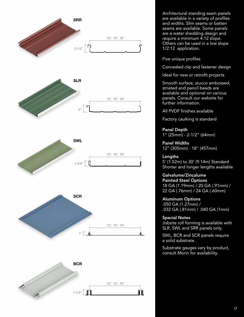
Five unique profiles
Concealed clip and fastener design
Ideal for new or retrofit projects
Smooth surface, stucco embossed, striated and pencil beads are available and optional on various panels. Consult our website for further information.
All PVDF finishes available
Factory caulking is standard
Architectural standing seam panels are available in a variety of profiles and widths. Slim seams or batten seams are available. Some panels are a water shedding design and require a minimum 4:12 slope. Others can be used in a low slope 1/2:12 application.
Panel Depth 1” (25mm) - 2-1/2” (64mm)
Panel Widths 12” (305mm) - 18” (457mm)
Lengths 5’ (1.52m) to 30’ (9.14m) Standard Shorter and longer lengths available
Galvalume/Zincalume Painted Steel Options 18 GA (1.19mm) / 20 GA (.91mm) / 22 GA (.76mm) / 24 GA (.60mm)
Aluminum Options .050 GA (1.27mm) / .032 GA (.81mm) / .040 GA (1mm)
Special Notes Jobsite roll forming is available with SLR, SWL and SRR panels only.
SWL, BCR and SCR panels require a solid substrate.
Substrate gauges vary by product, consult Morin for availability.
Morin’s Concealed Fastener wall panels are extremely versatile as they can be furnished as insulated or uninsulated systems and can be installed vertically or horizontally. Concealed Fastener panels can also be dismantled and reconstructed quickly. Optional stretch ribs are offered on many profiles.
SLR
BUTTON PUNCH
B-12
12"
1-1/2"
D-12
J-12
K-12
R-12
V-12
12"
1-1/2"
12"
1-1/2"
12"
1-1/2"
12"
1-1/2"
12"
1-1/2"
CONCEALED
A-12
AA-12
F-12-S
F-12-SW
F-12F-16F-18
N-12
T-12
W-12
TT-12
1-1/2"
12", 16", 18"
1-1/2"
12"
1-1/2"
12"
1-1/2"
1-1/2"
1-1/2"
1-1/2"
1-1/2"
1-1/2"
12"
11"
12"
11-1/2"
12"
6"6"
12"
8"4"
12"
10"2"
12"
1-1/4" 1-1/4"
1"
1/2"
BR9-36
36"
1-1/2"
EXPOSED
BR7-35
BR-28
C-37-7/8"C-29-7/8"
C-40-1/2
E8-40
E-30
E-36
MR-36
O-24
O-24W
VB-34
VB-36
Y-29Y-36
35"
1-1/2"
28"
1-1/2"
29-5/8" or 37-5/16"
7/8"
40"
1/2"
40"
1"
30"
1"
36"
1"
36"
3"
24"
4"
24"
4"
34-1/8"
1-3/4"
36"
1"
29" or 36"
1-1/2"
INTEGRITY
S-16
X-12
X-16
XAB-16
XB-12XB-16
XC-12
XD-12
XE-12XE-16
XF-12XF-16
XG-12
16"
7/8"
16"
7/8"
16"
7/8"
12"
7/8"
16"
7/8"
12" or 16"
7/8"
12"
7/8"
12"
7/8"
12" or 16"
7/8"
12" or 16"
7/8"
12"
7/8"
STANDING SEAM
BCR
SCR
SLR**
SRR**
12", 16", 18"
2-1/2"
12", 16", 18"
2"
SWL**
12", 16", 18"
1-3/4"
12", 16", 18"
1-1/2"
12", 16", 18"
1"
LINER PANELS
F-24
L3-24-3F
L-12 L-16
L-12-2FL2-12-2F
L-24-5FL2-24-5F
L-12W-1L-24W-2
24"
24"
3"
12" or 16"
3", 4-1/2", 6"
12"
1-1/2" or 2"
24"
12" or 24"
1-1/2" or 2"
1-5/16"
1-1/2"
SWL
BUTTON PUNCH
B-12
12"
1-1/2"
D-12
J-12
K-12
R-12
V-12
12"
1-1/2"
12"
1-1/2"
12"
1-1/2"
12"
1-1/2"
12"
1-1/2"
CONCEALED
A-12
AA-12
F-12-S
F-12-SW
F-12F-16F-18
N-12
T-12
W-12
TT-12
1-1/2"
12", 16", 18"
1-1/2"
12"
1-1/2"
12"
1-1/2"
1-1/2"
1-1/2"
1-1/2"
1-1/2"
1-1/2"
12"
11"
12"
11-1/2"
12"
6"6"
12"
8"4"
12"
10"2"
12"
1-1/4" 1-1/4"
1"
1/2"
BR9-36
36"
1-1/2"
EXPOSED
BR7-35
BR-28
C-37-7/8"C-29-7/8"
C-40-1/2
E8-40
E-30
E-36
MR-36
O-24
O-24W
VB-34
VB-36
Y-29Y-36
35"
1-1/2"
28"
1-1/2"
29-5/8" or 37-5/16"
7/8"
40"
1/2"
40"
1"
30"
1"
36"
1"
36"
3"
24"
4"
24"
4"
34-1/8"
1-3/4"
36"
1"
29" or 36"
1-1/2"
INTEGRITY
S-16
X-12
X-16
XAB-16
XB-12XB-16
XC-12
XD-12
XE-12XE-16
XF-12XF-16
XG-12
16"
7/8"
16"
7/8"
16"
7/8"
12"
7/8"
16"
7/8"
12" or 16"
7/8"
12"
7/8"
12"
7/8"
12" or 16"
7/8"
12" or 16"
7/8"
12"
7/8"
STANDING SEAM
BCR
SCR
SLR**
SRR**
12", 16", 18"
2-1/2"
12", 16", 18"
2"
SWL**
12", 16", 18"
1-3/4"
12", 16", 18"
1-1/2"
12", 16", 18"
1"
LINER PANELS
F-24
L3-24-3F
L-12 L-16
L-12-2FL2-12-2F
L-24-5FL2-24-5F
L-12W-1L-24W-2
24"
24"
3"
12" or 16"
3", 4-1/2", 6"
12"
1-1/2" or 2"
24"
12" or 24"
1-1/2" or 2"
1-5/16"
1-1/2"
BCR
BUTTON PUNCH
B-12
12"
1-1/2"
D-12
J-12
K-12
R-12
V-12
12"
1-1/2"
12"
1-1/2"
12"
1-1/2"
12"
1-1/2"
12"
1-1/2"
CONCEALED
A-12
AA-12
F-12-S
F-12-SW
F-12F-16F-18
N-12
T-12
W-12
TT-12
1-1/2"
12", 16", 18"
1-1/2"
12"
1-1/2"
12"
1-1/2"
1-1/2"
1-1/2"
1-1/2"
1-1/2"
1-1/2"
12"
11"
12"
11-1/2"
12"
6"6"
12"
8"4"
12"
10"2"
12"
1-1/4" 1-1/4"
1"
1/2"
BR9-36
36"
1-1/2"
EXPOSED
BR7-35
BR-28
C-37-7/8"C-29-7/8"
C-40-1/2
E8-40
E-30
E-36
MR-36
O-24
O-24W
VB-34
VB-36
Y-29Y-36
35"
1-1/2"
28"
1-1/2"
29-5/8" or 37-5/16"
7/8"
40"
1/2"
40"
1"
30"
1"
36"
1"
36"
3"
24"
4"
24"
4"
34-1/8"
1-3/4"
36"
1"
29" or 36"
1-1/2"
INTEGRITY
S-16
X-12
X-16
XAB-16
XB-12XB-16
XC-12
XD-12
XE-12XE-16
XF-12XF-16
XG-12
16"
7/8"
16"
7/8"
16"
7/8"
12"
7/8"
16"
7/8"
12" or 16"
7/8"
12"
7/8"
12"
7/8"
12" or 16"
7/8"
12" or 16"
7/8"
12"
7/8"
STANDING SEAM
BCR
SCR
SLR**
SRR**
12", 16", 18"
2-1/2"
12", 16", 18"
2"
SWL**
12", 16", 18"
1-3/4"
12", 16", 18"
1-1/2"
12", 16", 18"
1"
LINER PANELS
F-24
L3-24-3F
L-12 L-16
L-12-2FL2-12-2F
L-24-5FL2-24-5F
L-12W-1L-24W-2
24"
24"
3"
12" or 16"
3", 4-1/2", 6"
12"
1-1/2" or 2"
24"
12" or 24"
1-1/2" or 2"
1-5/16"
1-1/2"
SRR
BUTTON PUNCH
B-12
12"
1-1/2"
D-12
J-12
K-12
R-12
V-12
12"
1-1/2"
12"
1-1/2"
12"
1-1/2"
12"
1-1/2"
12"
1-1/2"
CONCEALED
A-12
AA-12
F-12-S
F-12-SW
F-12F-16F-18
N-12
T-12
W-12
TT-12
1-1/2"
12", 16", 18"
1-1/2"
12"
1-1/2"
12"
1-1/2"
1-1/2"
1-1/2"
1-1/2"
1-1/2"
1-1/2"
12"
11"
12"
11-1/2"
12"
6"6"
12"
8"4"
12"
10"2"
12"
1-1/4" 1-1/4"
1"
1/2"
BR9-36
36"
1-1/2"
EXPOSED
BR7-35
BR-28
C-37-7/8"C-29-7/8"
C-40-1/2
E8-40
E-30
E-36
MR-36
O-24
O-24W
VB-34
VB-36
Y-29Y-36
35"
1-1/2"
28"
1-1/2"
29-5/8" or 37-5/16"
7/8"
40"
1/2"
40"
1"
30"
1"
36"
1"
36"
3"
24"
4"
24"
4"
34-1/8"
1-3/4"
36"
1"
29" or 36"
1-1/2"
INTEGRITY
S-16
X-12
X-16
XAB-16
XB-12XB-16
XC-12
XD-12
XE-12XE-16
XF-12XF-16
XG-12
16"
7/8"
16"
7/8"
16"
7/8"
12"
7/8"
16"
7/8"
12" or 16"
7/8"
12"
7/8"
12"
7/8"
12" or 16"
7/8"
12" or 16"
7/8"
12"
7/8"
STANDING SEAM
BCR
SCR
SLR**
SRR**
12", 16", 18"
2-1/2"
12", 16", 18"
2"
SWL**
12", 16", 18"
1-3/4"
12", 16", 18"
1-1/2"
12", 16", 18"
1"
LINER PANELS
F-24
L3-24-3F
L-12 L-16
L-12-2FL2-12-2F
L-24-5FL2-24-5F
L-12W-1L-24W-2
24"
24"
3"
12" or 16"
3", 4-1/2", 6"
12"
1-1/2" or 2"
24"
12" or 24"
1-1/2" or 2"
1-5/16"
1-1/2"
SCR
BUTTON PUNCH
B-12
12"
1-1/2"
D-12
J-12
K-12
R-12
V-12
12"
1-1/2"
12"
1-1/2"
12"
1-1/2"
12"
1-1/2"
12"
1-1/2"
CONCEALED
A-12
AA-12
F-12-S
F-12-SW
F-12F-16F-18
N-12
T-12
W-12
TT-12
1-1/2"
12", 16", 18"
1-1/2"
12"
1-1/2"
12"
1-1/2"
1-1/2"
1-1/2"
1-1/2"
1-1/2"
1-1/2"
12"
11"
12"
11-1/2"
12"
6"6"
12"
8"4"
12"
10"2"
12"
1-1/4" 1-1/4"
1"
1/2"
BR9-36
36"
1-1/2"
EXPOSED
BR7-35
BR-28
C-37-7/8"C-29-7/8"
C-40-1/2
E8-40
E-30
E-36
MR-36
O-24
O-24W
VB-34
VB-36
Y-29Y-36
35"
1-1/2"
28"
1-1/2"
29-5/8" or 37-5/16"
7/8"
40"
1/2"
40"
1"
30"
1"
36"
1"
36"
3"
24"
4"
24"
4"
34-1/8"
1-3/4"
36"
1"
29" or 36"
1-1/2"
INTEGRITY
S-16
X-12
X-16
XAB-16
XB-12XB-16
XC-12
XD-12
XE-12XE-16
XF-12XF-16
XG-12
16"
7/8"
16"
7/8"
16"
7/8"
12"
7/8"
16"
7/8"
12" or 16"
7/8"
12"
7/8"
12"
7/8"
12" or 16"
7/8"
12" or 16"
7/8"
12"
7/8"
STANDING SEAM
BCR
SCR
SLR**
SRR**
12", 16", 18"
2-1/2"
12", 16", 18"
2"
SWL**
12", 16", 18"
1-3/4"
12", 16", 18"
1-1/2"
12", 16", 18"
1"
LINER PANELS
F-24
L3-24-3F
L-12 L-16
L-12-2FL2-12-2F
L-24-5FL2-24-5F
L-12W-1L-24W-2
24"
24"
3"
12" or 16"
3", 4-1/2", 6"
12"
1-1/2" or 2"
24"
12" or 24"
1-1/2" or 2"
1-5/16"
1-1/2"
17