new ww hastings hospital geotechnical investigation rfp ...€¦ · 10838 e. marshall street, ......
TRANSCRIPT
10838 E. Marshall Street, Suite 220
Tulsa, OK 74116 918‐582‐9110 ‐ Phone
918‐583‐7948 ‐ FAX
New WW Hastings Hospital Geotechnical Investigation RFP
Addendum #1
DATE: April 29, 2014 ADDENDUM NO.: 1 PROJECT: New WW Hastings Hospital BID PACKAGE NO: Geotechnical Investigation RFP SUBMITTED BY: CNCR
1. Please find attached Preliminary Subsurface Exploration Letter dated November 25, 2013 for the Proposed WW Hastings Hospital Additions. This letter is provided for bidder information only and will not be considered in the event that the site conditions differ from the preliminary report.
‐‐END OF ADDENDUM 1‐‐
TUL13L0928 Page 1 of 4 December 4, 2013 Copyright 2013 Kleinfelder
November 25, 2013
Mr. Andrew Ruleford, Project Manager Cherokee Nation Construction Resources, LLC 10838 East Marshall Street, Suite 220 Tulsa, Oklahoma 74116 Subject: Preliminary Subsurface Exploration Letter
Proposed W.W. Hastings Hospital Additions Tahlequah, Oklahoma Project No.: 138059
Dear Mr. Ruleford In accordance with your request, Kleinfelder has completed the authorized soil borings and laboratory testing for the above referenced project. The services provided were in general accordance with our
Proposal TUL 13P0879 dated November 15, 2013. At this time, the location, number of stories, type of building, and loading conditions are not available. The exact location of the parking area is also not available. A grading plan has not been developed. However, the proposed building additions and parking areas will be added to the east and south side of the existing hospital building. The purpose of the preliminary geotechnical engineering services is to obtain general subsurface conditions (soil types, depth to bedrock) and evaluate suitable foundation types for the proposed additions. Foundation recommendations (bearing capacity, bearing depth, etc) are beyond the scope of this project, and a detailed geotechnical investigation will be performed when the location and details of the proposed additions are developed.
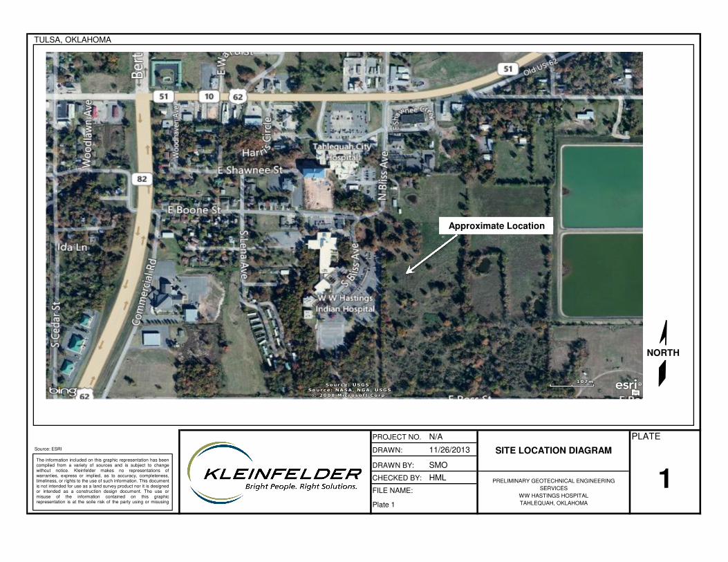
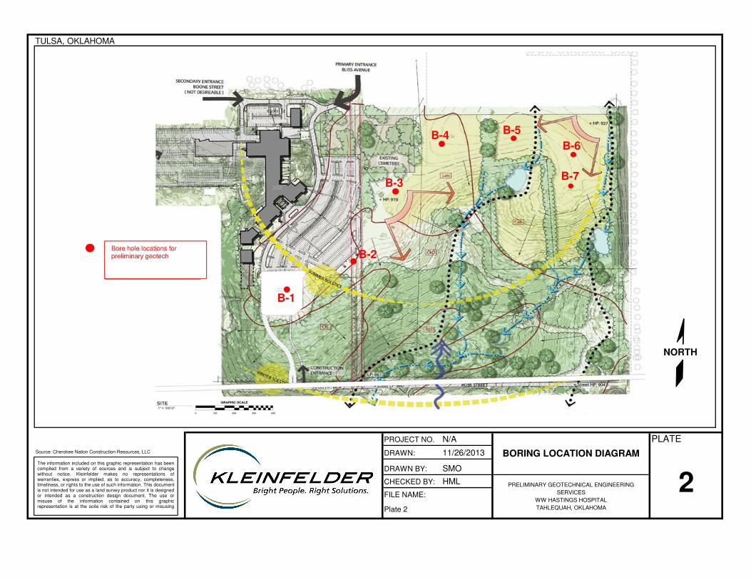
Kleinfelder conducted the field work on November 20, 2013, which consisted of seven (7) borings that extended to approximate depths of 15.0 feet below the existing grade or auger refusal. The approximate location of the site is presented on the attached Plate 1, Site Location Diagram. The borings were performed near the locations indicated on the proposal TUL13P0879, and are presented on the attached Plate 2, Boring Location Diagram. Elevations at the boring locations were not available.
The borings were performed with a track mounted (CME-45C) rotary drill rig using solid flight augers to advance the borings. Samples were obtained by performing a Standard Penetration test (SPT) using a 2-inch O.D. split-barrel sampler. Split-barrel sampling was conducted in general accordance with ASTM D1586 (Standard Test Method for Standard Penetration Test and Split-Barrel Sampling of Soils). The split-barrel sampler is driven into the bottom of the boring over an 18-inch sampling interval by a 140-pound hammer that is dropped a distance of 30 inches. A CME automatic SPT hammer with an approximate hammer efficiency of 76 percent was used to advance the split-barrel
Interchange Business Park, 10835 East Independence, Suite 102, Tulsa, OK 74116-5680 p| 918.627.6161 f| 918.627.6262

TUL13L0928 Page 2 of 4 December 4, 2013 Copyright 2013 Kleinfelder
sampler. The SPT N-value, recorded on the boring logs, is the number of blows required to drive the split-barrel sampler the final 12 inches of the 18-inch sampling interval.
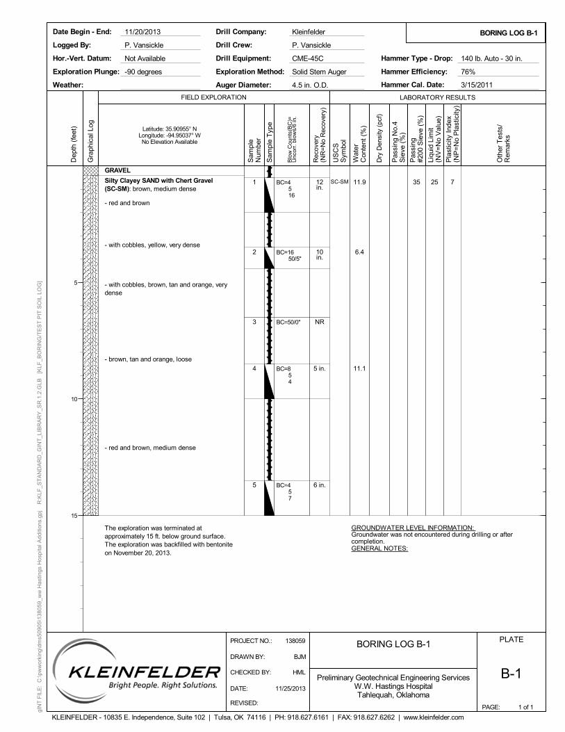
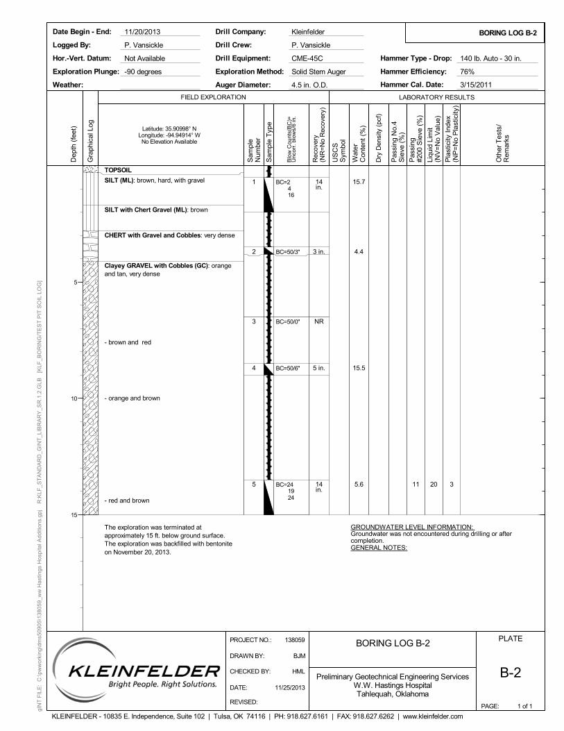
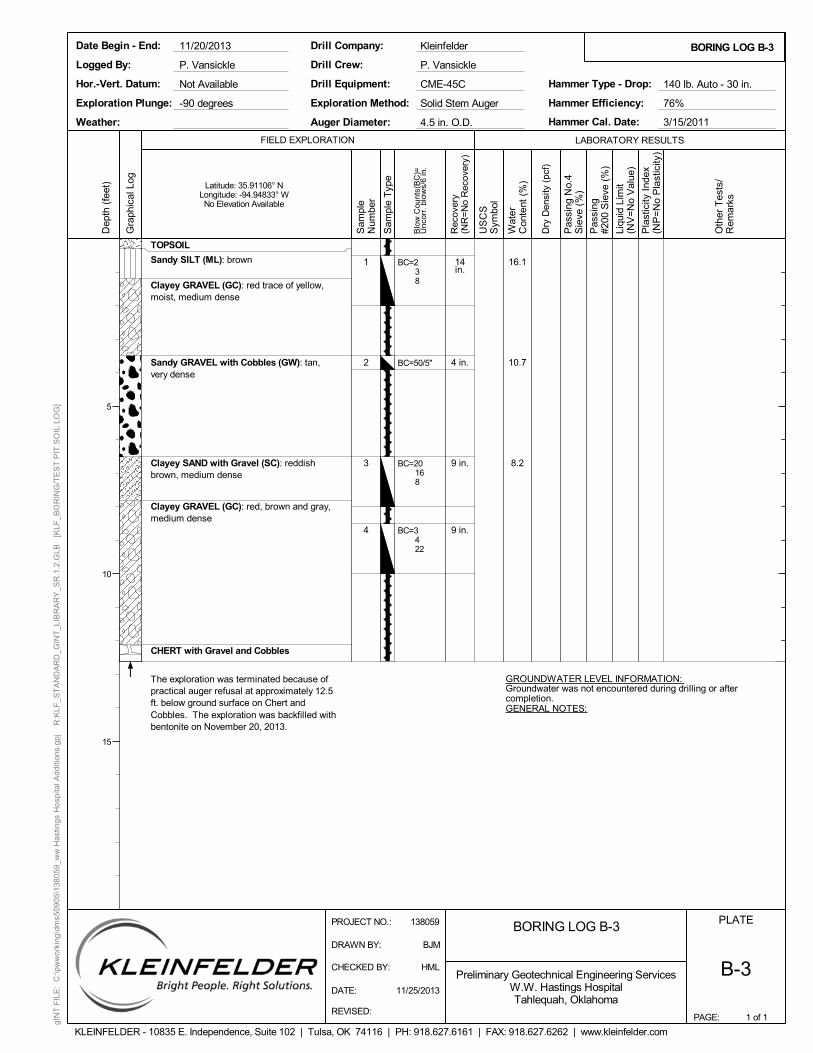
Boring B-1 was drilled in an existing gravel covered parking area with approximately 5-inches of gravel surfacing. Approximately 3 to 4 inches of topsoil was encountered at the surface in Borings B-2 to B-7. Native soils encountered below the gravel and topsoil were generally comprised of clay and gravel with varying amounts of silt, sand, and chert and limestone gravels and cobbles, and extended to the bottom of the borings. Auger refusal was encountered in Boring B-3 at a depth of approximately twelve feet below the existing ground surface in chert cobbles. Generally, the upper layers of the native soils were firm to hard, overlaying loose materials encountered in the lower portion of the borings. Silty, clayey sand with a relative density of loose to very dense was encountered in Boring B-1. Sand and gravel with relative densities of loose to very dense were encountered in Borings B-2 through B-7. Bedrock was not encountered within the exploration limits.
No groundwater was encountered within the borings at the completion of drilling. However, the materials encountered in the test borings can have a wide range of permeability, and observations over an extended period of time, through use of piezometers or cased borings, would be required to better define groundwater conditions. Fluctuations of groundwater levels can occur due to seasonal variations in the amount of rainfall, runoff, and other factors not evident at the time the borings were performed. The possibility of groundwater level fluctuations should be considered when developing the design and construction plans for the project.
Field logs included visual classification of the materials encountered during drilling, as well as drilling characteristics. Our final boring logs represent the engineer’s interpretation of the field logs combined with laboratory observation and testing of the samples. Stratification boundaries indicated on the boring logs were based on observations during our field work, an extrapolation of information obtained by examining samples from the borings, and comparisons to soils with similar engineering characteristics. Locations of these boundaries are approximate, and the transitions between material types may be gradual rather than clearly defined. Copies of the boring logs are attached.
Atterberg limits and sieve analysis tests were performed on selected samples for classification purposes. Additional testing/observation of the samples were limited to moisture content and visually classifying the subsurface materials. Laboratory tests were performed in general accordance with applicable standards. The results of the tests are presented on the respective boring logs. Boring logs included in this appendix present such data as soil and bedrock descriptions, depths, sampling intervals, and observed groundwater conditions. Conditions encountered in each of the borings were monitored and recorded by the drill crew.
The site is generally sloping downward to the south. It is anticipated that cut on the north, and fill on the south will be required to achieve the final design grade. However, the amounts of cut and fill are not available at this time. Based on the results of field exploration and laboratory testing, it is our opinion that a shallow foundation system could be used for a one to two-story structure, provided that the structural loadings are relatively light to moderate (column loads less than 50 kips). A multi-floor structure with moderate to heavy structural loads may require a drilled pier foundation system. The shallow foundation system which includes spread and wall footings can be constructed with conventional grading and construction techniques. The drilled pier foundation system will require more difficult drilling techniques to penetrate through the subsurface layers with gravel and cobbles.

TUL13L0928 Page 3 of 4 December 4, 2013 Copyright 2013 Kleinfelder
Casing maybe required for the installation of drilled pier foundation system to prevent the cave-in of the gravel and cobbles. It is anticipated that fills higher than 5 feet will result in the settlement of the subsurface soils. Settlement monitoring will be required to ensure that primary settlement of the subsurface materials is completed prior to the construction of the proposed buildings and structures supported on the fill materials.
When the building and parking layout are delineated, a detailed subsurface exploration and geotechnical engineering services should be performed. Depending on the structural loading, the geotechnical exploration depths will need to be modified to obtain sufficient samples of subsurface conditions. For structures with light to moderate building loads, and with cut no more than 5 feet, it is recommended to extend the geotechnical borings to a minimum depth of 20 feet below the proposed final grade. For structures with moderate to heavy loads, or where proposed cut exceeds 5 feet to achieve the final grade, the borings should extend to the top of bedrock. At this time, it is difficult to estimate the depth to bedrock, but it is anticipated to be within 40 feet of the existing ground surface.
********************************************************************************************************************
Recommendations contained in this report are based on our field observations and subsurface explorations, limited laboratory tests, and our present knowledge of the proposed construction. It is possible that subsurface conditions could vary between or beyond the points explored. If subsurface conditions are encountered during construction that differ from those described herein, we should be notified immediately in order that a review may be made and any supplemental recommendations provided. If the scope of the proposed construction, including the proposed loads or structural locations, changes from that described in this report, our recommendations should also be reviewed.
We have prepared this report in substantial accordance with the generally accepted geotechnical engineering practice as it exists in the site area at the time of our study. No warranty is expressed or implied. The recommendations provided in this report are based on the assumption that Kleinfelder will conduct an adequate program of tests and observations during the construction phase in order to evaluate compliance with our recommendations. The scope of our services did not include any environmental assessment or exploration for the presence of hazardous or toxic materials in the soil, surface water, groundwater or air, on, below or around this site.
This report may be used only by the client and only for the purposes stated, within a reasonable time from its issuance, but in no event later than three years from the date of report. Land use, site conditions (both on-site and off-site), regulations, or other factors may change over time, and additional work may be required with the passage of time. Any party other than the client who wishes to use this report shall notify Kleinfelder of such intended use. Based on the intended use of the report, Kleinfelder may require that additional work be performed and that an updated report be issued. Non-compliance with any of these requirements by the client or anyone else will release Kleinfelder from any liability resulting from the use of this report by any unauthorized party and client agrees to defend, indemnify and hold harmless Kleinfelder from any claim or liability associated with such unauthorized or non-compliance.
PROJECT NO. N/A
DRAWN: 11/26/2013
DRAWN BY: SMO
CHECKED BY: HML
FILE NAME:
SITE LOCATION DIAGRAM
PLATE
Source: ESRI
1PRELIMINARY GEOTECHNICAL ENGINEERING
SERVICES
WW HASTINGS HOSPITAL
TAHLEQUAH, OKLAHOMAPlate 1
The information included on this graphic representation has beencompiled from a variety of sources and is subject to changewithout notice. Kleinfelder makes no representations ofwarranties, express or implied, as to accuracy, completeness,timeliness, or rights to the use of such information. This documentis not intended for use as a land survey product nor it is designedor intended as a construction design document. The use ormisuse of the information contained on this graphicrepresentation is at the soile risk of the party using or misusing
TULSA, OKLAHOMA
NORTH
Approximate Location
PROJECT NO. N/A
DRAWN: 11/26/2013
DRAWN BY: SMO
CHECKED BY: HML
FILE NAME:
Source: Cherokee Nation Construction Resources, LLC BORING LOCATION DIAGRAM
PLATE
2PRELIMINARY GEOTECHNICAL ENGINEERING
SERVICES
WW HASTINGS HOSPITAL
TAHLEQUAH, OKLAHOMAPlate 2
The information included on this graphic representation has beencompiled from a variety of sources and is subject to changewithout notice. Kleinfelder makes no representations ofwarranties, express or implied, as to accuracy, completeness,timeliness, or rights to the use of such information. This documentis not intended for use as a land survey product nor it is designedor intended as a construction design document. The use ormisuse of the information contained on this graphicrepresentation is at the soile risk of the party using or misusing
TULSA, OKLAHOMA
B-1
B-2
B-3
B-4 B-5
B-6
B-7
NORTH
Bore hole locations for preliminary geotech
1
2
3
4
5
12in.
10in.
NR
5 in.
6 in.
SC-SM 11.9
6.4
11.1
35 25 7
GROUNDWATER LEVEL INFORMATION: Groundwater was not encountered during drilling or aftercompletion.GENERAL NOTES:
GRAVEL
Silty Clayey SAND with Chert Gravel(SC-SM): brown, medium dense
- red and brown
- with cobbles, yellow, very dense
- with cobbles, brown, tan and orange, verydense
- brown, tan and orange, loose
- red and brown, medium dense
The exploration was terminated atapproximately 15 ft. below ground surface.The exploration was backfilled with bentoniteon November 20, 2013.
BC=4516
BC=1650/5"
BC=50/0"
BC=854
BC=457
PAGE:
FIELD EXPLORATION
BORING LOG B-1
1 of 1
BORING LOG B-1
PLATE
B-1
LABORATORY RESULTS
Dep
th (
feet
)
5
10
15
Gra
phic
al L
og
Sam
ple
Num
ber
Rec
over
y(N
R=
No
Rec
over
y)
US
CS
Sym
bol
Wat
erC
onte
nt (
%)
Dry
Den
sity
(pc
f)
Pas
sing
No.
4S
ieve
(%
)
Pas
sing
#200
Sie
ve (
%)
Liqu
id L
imit
(NV
=N
o V
alue
)
Pla
stic
ity I
ndex
(NP
=N
o P
last
icity
)
Preliminary Geotechnical Engineering ServicesW.W. Hastings HospitalTahlequah, Oklahoma
KLEINFELDER - 10835 E. Independence, Suite 102 | Tulsa, OK 74116 | PH: 918.627.6161 | FAX: 918.627.6262 | www.kleinfelder.com
Latitude: 35.90955° NLongitude: -94.95037° WNo Elevation Available
P. Vansickle
Exploration Method:
Logged By:
Date Begin - End:
Hor.-Vert. Datum:
Weather:
Drill Equipment:
Drill Crew:
Drill Company:
Hammer Efficiency: 76%
Hammer Cal. Date:
Hammer Type - Drop:Not Available
Solid Stem Auger
CME-45C
P. Vansickle
Kleinfelder
Auger Diameter:
11/20/2013
3/15/2011
140 lb. Auto - 30 in.
4.5 in. O.D.
Exploration Plunge: -90 degrees
Oth
er T
ests
/R
emar
ks
Blo
w C
ount
s(B
C)=
Unc
orr.
blo
ws/
6 in
.
gIN
T F
ILE
: C
:\pw
wor
king
\dm
s509
05\1
380
59_w
w H
astin
gs H
ospi
tal A
dditi
ons.
gpj
R:K
LF_S
TA
ND
AR
D_G
INT
_LIB
RA
RY
_SR
.1.2
.GLB
[K
LF_B
OR
ING
/TE
ST
PIT
SO
IL L
OG
]
PROJECT NO.: 138059
DRAWN BY: BJM
CHECKED BY: HML
DATE: 11/25/2013
REVISED:
Sam
ple
Typ
e
1
2
3
4
5
14in.
3 in.
NR
5 in.
14in.
15.7
4.4
15.5
5.6 11 20 3
GROUNDWATER LEVEL INFORMATION: Groundwater was not encountered during drilling or aftercompletion.GENERAL NOTES:
TOPSOIL
SILT (ML): brown, hard, with gravel
SILT with Chert Gravel (ML): brown
CHERT with Gravel and Cobbles: very dense
Clayey GRAVEL with Cobbles (GC): orangeand tan, very dense
- brown and red
- orange and brown
- red and brown
The exploration was terminated atapproximately 15 ft. below ground surface.The exploration was backfilled with bentoniteon November 20, 2013.
BC=2416
BC=50/3"
BC=50/0"
BC=50/6"
BC=241924
PAGE:
FIELD EXPLORATION
BORING LOG B-2
1 of 1
BORING LOG B-2
PLATE
B-2
LABORATORY RESULTS
Dep
th (
feet
)
5
10
15
Gra
phic
al L
og
Sam
ple
Num
ber
Rec
over
y(N
R=
No
Rec
over
y)
US
CS
Sym
bol
Wat
erC
onte
nt (
%)
Dry
Den
sity
(pc
f)
Pas
sing
No.
4S
ieve
(%
)
Pas
sing
#200
Sie
ve (
%)
Liqu
id L
imit
(NV
=N
o V
alue
)
Pla
stic
ity I
ndex
(NP
=N
o P
last
icity
)
Preliminary Geotechnical Engineering ServicesW.W. Hastings HospitalTahlequah, Oklahoma
KLEINFELDER - 10835 E. Independence, Suite 102 | Tulsa, OK 74116 | PH: 918.627.6161 | FAX: 918.627.6262 | www.kleinfelder.com
Latitude: 35.90998° NLongitude: -94.94914° WNo Elevation Available
P. Vansickle
Exploration Method:
Logged By:
Date Begin - End:
Hor.-Vert. Datum:
Weather:
Drill Equipment:
Drill Crew:
Drill Company:
Hammer Efficiency: 76%
Hammer Cal. Date:
Hammer Type - Drop:Not Available
Solid Stem Auger
CME-45C
P. Vansickle
Kleinfelder
Auger Diameter:
11/20/2013
3/15/2011
140 lb. Auto - 30 in.
4.5 in. O.D.
Exploration Plunge: -90 degrees
Oth
er T
ests
/R
emar
ks
Blo
w C
ount
s(B
C)=
Unc
orr.
blo
ws/
6 in
.
gIN
T F
ILE
: C
:\pw
wor
king
\dm
s509
05\1
380
59_w
w H
astin
gs H
ospi
tal A
dditi
ons.
gpj
R:K
LF_S
TA
ND
AR
D_G
INT
_LIB
RA
RY
_SR
.1.2
.GLB
[K
LF_B
OR
ING
/TE
ST
PIT
SO
IL L
OG
]
PROJECT NO.: 138059
DRAWN BY: BJM
CHECKED BY: HML
DATE: 11/25/2013
REVISED:
Sam
ple
Typ
e
1
2
3
4
14in.
4 in.
9 in.
9 in.
16.1
10.7
8.2
GROUNDWATER LEVEL INFORMATION: Groundwater was not encountered during drilling or aftercompletion.GENERAL NOTES:
TOPSOIL
Sandy SILT (ML): brown
Clayey GRAVEL (GC): red trace of yellow,moist, medium dense
Sandy GRAVEL with Cobbles (GW): tan,very dense
Clayey SAND with Gravel (SC): reddishbrown, medium dense
Clayey GRAVEL (GC): red, brown and gray,medium dense
CHERT with Gravel and Cobbles
The exploration was terminated because ofpractical auger refusal at approximately 12.5ft. below ground surface on Chert andCobbles. The exploration was backfilled withbentonite on November 20, 2013.
BC=238
BC=50/5"
BC=20168
BC=3422
PAGE:
FIELD EXPLORATION
BORING LOG B-3
1 of 1
BORING LOG B-3
PLATE
B-3
LABORATORY RESULTS
Dep
th (
feet
)
5
10
15
Gra
phic
al L
og
Sam
ple
Num
ber
Rec
over
y(N
R=
No
Rec
over
y)
US
CS
Sym
bol
Wat
erC
onte
nt (
%)
Dry
Den
sity
(pc
f)
Pas
sing
No.
4S
ieve
(%
)
Pas
sing
#200
Sie
ve (
%)
Liqu
id L
imit
(NV
=N
o V
alue
)
Pla
stic
ity I
ndex
(NP
=N
o P
last
icity
)
Preliminary Geotechnical Engineering ServicesW.W. Hastings HospitalTahlequah, Oklahoma
KLEINFELDER - 10835 E. Independence, Suite 102 | Tulsa, OK 74116 | PH: 918.627.6161 | FAX: 918.627.6262 | www.kleinfelder.com
Latitude: 35.91106° NLongitude: -94.94833° WNo Elevation Available
P. Vansickle
Exploration Method:
Logged By:
Date Begin - End:
Hor.-Vert. Datum:
Weather:
Drill Equipment:
Drill Crew:
Drill Company:
Hammer Efficiency: 76%
Hammer Cal. Date:
Hammer Type - Drop:Not Available
Solid Stem Auger
CME-45C
P. Vansickle
Kleinfelder
Auger Diameter:
11/20/2013
3/15/2011
140 lb. Auto - 30 in.
4.5 in. O.D.
Exploration Plunge: -90 degrees
Oth
er T
ests
/R
emar
ks
Blo
w C
ount
s(B
C)=
Unc
orr.
blo
ws/
6 in
.
gIN
T F
ILE
: C
:\pw
wor
king
\dm
s509
05\1
380
59_w
w H
astin
gs H
ospi
tal A
dditi
ons.
gpj
R:K
LF_S
TA
ND
AR
D_G
INT
_LIB
RA
RY
_SR
.1.2
.GLB
[K
LF_B
OR
ING
/TE
ST
PIT
SO
IL L
OG
]
PROJECT NO.: 138059
DRAWN BY: BJM
CHECKED BY: HML
DATE: 11/25/2013
REVISED:
Sam
ple
Typ
e

1
2
3
4
5
5 in.
14in.
10in.
12in.
14in.
11.4
6.9
8.5
11
GROUNDWATER LEVEL INFORMATION: Groundwater was not encountered during drilling or aftercompletion.GENERAL NOTES:
TOPSOIL
Sandy SILT (ML): brown
Clayey GRAVEL (GC): red and brown, loose
- red and yellow, very dense
- medium dense
Sandy Lean to Fat CLAY with Gravel(CL-CH): gray trace of red and yellow,medium dense
Sandy Fat CLAY with Chert Gravel (CH): red,very hard
The exploration was terminated atapproximately 15 ft. below ground surface.The exploration was backfilled with bentoniteon November 20, 2013.
BC=333
BC=242929
BC=13148
BC=21146
BC=193250/4"
PAGE:
FIELD EXPLORATION
BORING LOG B-4
1 of 1
BORING LOG B-4
PLATE
B-4
LABORATORY RESULTS
Dep
th (
feet
)
5
10
15
Gra
phic
al L
og
Sam
ple
Num
ber
Rec
over
y(N
R=
No
Rec
over
y)
US
CS
Sym
bol
Wat
erC
onte
nt (
%)
Dry
Den
sity
(pc
f)
Pas
sing
No.
4S
ieve
(%
)
Pas
sing
#200
Sie
ve (
%)
Liqu
id L
imit
(NV
=N
o V
alue
)
Pla
stic
ity I
ndex
(NP
=N
o P
last
icity
)
Preliminary Geotechnical Engineering ServicesW.W. Hastings HospitalTahlequah, Oklahoma
KLEINFELDER - 10835 E. Independence, Suite 102 | Tulsa, OK 74116 | PH: 918.627.6161 | FAX: 918.627.6262 | www.kleinfelder.com
Latitude: 35.91181° NLongitude: -94.94746° WNo Elevation Available
P. Vansickle
Exploration Method:
Logged By:
Date Begin - End:
Hor.-Vert. Datum:
Weather:
Drill Equipment:
Drill Crew:
Drill Company:
Hammer Efficiency: 76%
Hammer Cal. Date:
Hammer Type - Drop:Not Available
Solid Stem Auger
CME-45C
P. Vansickle
Kleinfelder
Auger Diameter:
11/20/2013
3/15/2011
140 lb. Auto - 30 in.
4.5 in. O.D.
Exploration Plunge: -90 degrees
Oth
er T
ests
/R
emar
ks
Blo
w C
ount
s(B
C)=
Unc
orr.
blo
ws/
6 in
.
gIN
T F
ILE
: C
:\pw
wor
king
\dm
s509
05\1
380
59_w
w H
astin
gs H
ospi
tal A
dditi
ons.
gpj
R:K
LF_S
TA
ND
AR
D_G
INT
_LIB
RA
RY
_SR
.1.2
.GLB
[K
LF_B
OR
ING
/TE
ST
PIT
SO
IL L
OG
]
PROJECT NO.: 138059
DRAWN BY: BJM
CHECKED BY: HML
DATE: 11/25/2013
REVISED:
Sam
ple
Typ
e
1
2
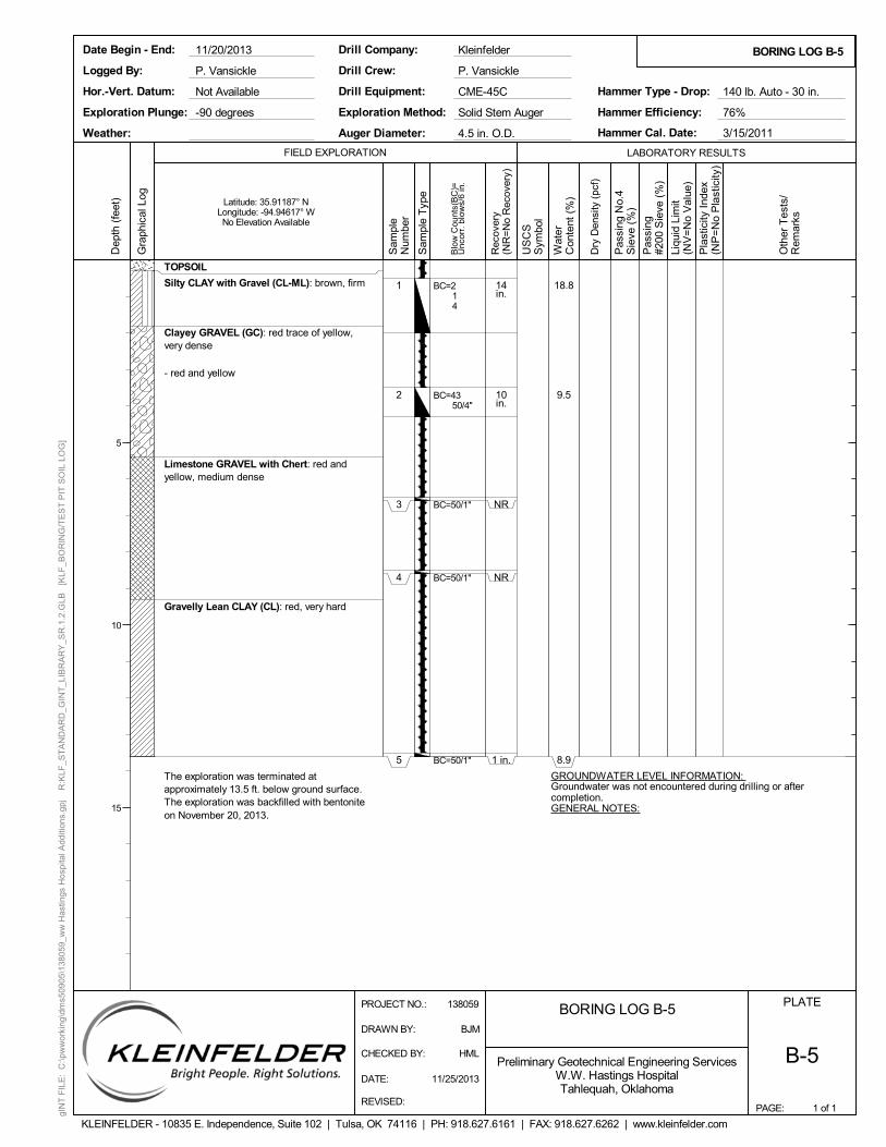
3
4
5
14in.
10in.
NR
NR
1 in.
18.8
9.5
8.9
GROUNDWATER LEVEL INFORMATION: Groundwater was not encountered during drilling or aftercompletion.GENERAL NOTES:
TOPSOIL
Silty CLAY with Gravel (CL-ML): brown, firm
Clayey GRAVEL (GC): red trace of yellow,very dense
- red and yellow
Limestone GRAVEL with Chert: red andyellow, medium dense
Gravelly Lean CLAY (CL): red, very hard
The exploration was terminated atapproximately 13.5 ft. below ground surface.The exploration was backfilled with bentoniteon November 20, 2013.
BC=214
BC=4350/4"
BC=50/1"
BC=50/1"
BC=50/1"
PAGE:
FIELD EXPLORATION
BORING LOG B-5
1 of 1
BORING LOG B-5
PLATE
B-5
LABORATORY RESULTS
Dep
th (
feet
)
5
10
15
Gra
phic
al L
og
Sam
ple
Num
ber
Rec
over
y(N
R=
No
Rec
over
y)
US
CS
Sym
bol
Wat
erC
onte
nt (
%)
Dry
Den
sity
(pc
f)
Pas
sing
No.
4S
ieve
(%
)
Pas
sing
#200
Sie
ve (
%)
Liqu
id L
imit
(NV
=N
o V
alue
)
Pla
stic
ity I
ndex
(NP
=N
o P
last
icity
)
Preliminary Geotechnical Engineering ServicesW.W. Hastings HospitalTahlequah, Oklahoma
KLEINFELDER - 10835 E. Independence, Suite 102 | Tulsa, OK 74116 | PH: 918.627.6161 | FAX: 918.627.6262 | www.kleinfelder.com
Latitude: 35.91187° NLongitude: -94.94617° WNo Elevation Available
P. Vansickle
Exploration Method:
Logged By:
Date Begin - End:
Hor.-Vert. Datum:
Weather:
Drill Equipment:
Drill Crew:
Drill Company:
Hammer Efficiency: 76%
Hammer Cal. Date:
Hammer Type - Drop:Not Available
Solid Stem Auger
CME-45C
P. Vansickle
Kleinfelder
Auger Diameter:
11/20/2013
3/15/2011
140 lb. Auto - 30 in.
4.5 in. O.D.
Exploration Plunge: -90 degrees
Oth
er T
ests
/R
emar
ks
Blo
w C
ount
s(B
C)=
Unc
orr.
blo
ws/
6 in
.
gIN
T F
ILE
: C
:\pw
wor
king
\dm
s509
05\1
380
59_w
w H
astin
gs H
ospi
tal A
dditi
ons.
gpj
R:K
LF_S
TA
ND
AR
D_G
INT
_LIB
RA
RY
_SR
.1.2
.GLB
[K
LF_B
OR
ING
/TE
ST
PIT
SO
IL L
OG
]
PROJECT NO.: 138059
DRAWN BY: BJM
CHECKED BY: HML
DATE: 11/25/2013
REVISED:
Sam
ple
Typ
e

1
2
3
4
5
14in.
5 in.
11in.
11in.
18in.
19.6
8.1
8.1
GROUNDWATER LEVEL INFORMATION: Groundwater was not encountered during drilling or aftercompletion.GENERAL NOTES:
TOPSOIL
Lean to Fat CLAY with Siltstone nodules(CL-CH): brown, soft
Gravelly CLAY (GC): red and yellow, veryhard
Clayey GRAVEL (GC): red and yellow, verydense
Sandy Fat CLAY (CH): red trace of yellow
- tan trace of gray and yellow, hard
The exploration was terminated atapproximately 15 ft. below ground surface.The exploration was backfilled with bentoniteon November 20, 2013.
BC=213
BC=50/5"
BC=4850/5"
BC=3850/5"
BC=497
PAGE:
FIELD EXPLORATION
BORING LOG B-6
1 of 1
BORING LOG B-6
PLATE
B-6
LABORATORY RESULTS
Dep
th (
feet
)
5
10
15
Gra
phic
al L
og
Sam
ple
Num
ber
Rec
over
y(N
R=
No
Rec
over
y)
US
CS
Sym
bol
Wat
erC
onte
nt (
%)
Dry
Den
sity
(pc
f)
Pas
sing
No.
4S
ieve
(%
)
Pas
sing
#200
Sie
ve (
%)
Liqu
id L
imit
(NV
=N
o V
alue
)
Pla
stic
ity I
ndex
(NP
=N
o P
last
icity
)
Preliminary Geotechnical Engineering ServicesW.W. Hastings HospitalTahlequah, Oklahoma
KLEINFELDER - 10835 E. Independence, Suite 102 | Tulsa, OK 74116 | PH: 918.627.6161 | FAX: 918.627.6262 | www.kleinfelder.com
Latitude: 35.91158° NLongitude: -94.94514° WNo Elevation Available
P. Vansickle
Exploration Method:
Logged By:
Date Begin - End:
Hor.-Vert. Datum:
Weather:
Drill Equipment:
Drill Crew:
Drill Company:
Hammer Efficiency: 76%
Hammer Cal. Date:
Hammer Type - Drop:Not Available
Solid Stem Auger
CME-45C
P. Vansickle
Kleinfelder
Auger Diameter:
11/20/2013
3/15/2011
140 lb. Auto - 30 in.
4.5 in. O.D.
Exploration Plunge: -90 degrees
Oth
er T
ests
/R
emar
ks
Blo
w C
ount
s(B
C)=
Unc
orr.
blo
ws/
6 in
.
gIN
T F
ILE
: C
:\pw
wor
king
\dm
s509
05\1
380
59_w
w H
astin
gs H
ospi
tal A
dditi
ons.
gpj
R:K
LF_S
TA
ND
AR
D_G
INT
_LIB
RA
RY
_SR
.1.2
.GLB
[K
LF_B
OR
ING
/TE
ST
PIT
SO
IL L
OG
]
PROJECT NO.: 138059
DRAWN BY: BJM
CHECKED BY: HML
DATE: 11/25/2013
REVISED:
Sam
ple
Typ
e
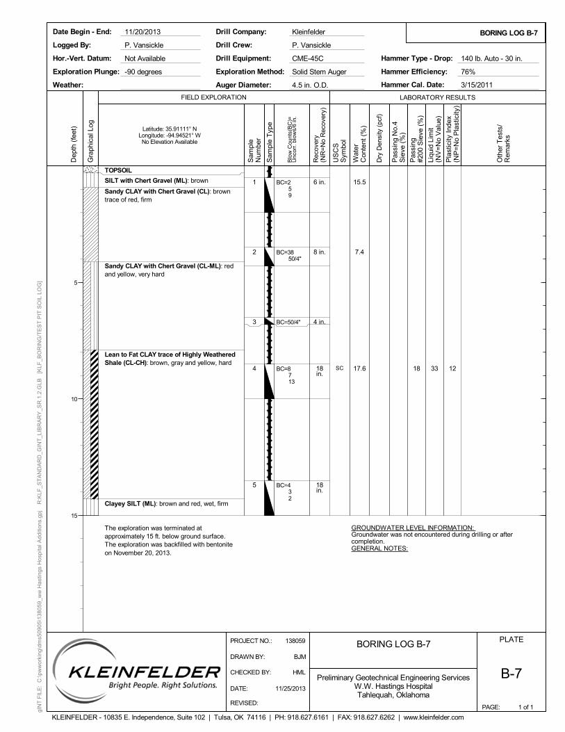
1
2
3
4
5
6 in.
8 in.
4 in.
18in.
18in.
SC
15.5
7.4
17.6 18 33 12
GROUNDWATER LEVEL INFORMATION: Groundwater was not encountered during drilling or aftercompletion.GENERAL NOTES:
TOPSOIL
SILT with Chert Gravel (ML): brown
Sandy CLAY with Chert Gravel (CL): browntrace of red, firm
Sandy CLAY with Chert Gravel (CL-ML): redand yellow, very hard
Lean to Fat CLAY trace of Highly WeatheredShale (CL-CH): brown, gray and yellow, hard
Clayey SILT (ML): brown and red, wet, firm
The exploration was terminated atapproximately 15 ft. below ground surface.The exploration was backfilled with bentoniteon November 20, 2013.
BC=259
BC=3850/4"
BC=50/4"
BC=8713
BC=432
PAGE:
FIELD EXPLORATION
BORING LOG B-7
1 of 1
BORING LOG B-7
PLATE
B-7
LABORATORY RESULTS
Dep
th (
feet
)
5
10
15
Gra
phic
al L
og
Sam
ple
Num
ber
Rec
over
y(N
R=
No
Rec
over
y)
US
CS
Sym
bol
Wat
erC
onte
nt (
%)
Dry
Den
sity
(pc
f)
Pas
sing
No.
4S
ieve
(%
)
Pas
sing
#200
Sie
ve (
%)
Liqu
id L
imit
(NV
=N
o V
alue
)
Pla
stic
ity I
ndex
(NP
=N
o P
last
icity
)
Preliminary Geotechnical Engineering ServicesW.W. Hastings HospitalTahlequah, Oklahoma
KLEINFELDER - 10835 E. Independence, Suite 102 | Tulsa, OK 74116 | PH: 918.627.6161 | FAX: 918.627.6262 | www.kleinfelder.com
Latitude: 35.91111° NLongitude: -94.94521° WNo Elevation Available
P. Vansickle
Exploration Method:
Logged By:
Date Begin - End:
Hor.-Vert. Datum:
Weather:
Drill Equipment:
Drill Crew:
Drill Company:
Hammer Efficiency: 76%
Hammer Cal. Date:
Hammer Type - Drop:Not Available
Solid Stem Auger
CME-45C
P. Vansickle
Kleinfelder
Auger Diameter:
11/20/2013
3/15/2011
140 lb. Auto - 30 in.
4.5 in. O.D.
Exploration Plunge: -90 degrees
Oth
er T
ests
/R
emar
ks
Blo
w C
ount
s(B
C)=
Unc
orr.
blo
ws/
6 in
.
gIN
T F
ILE
: C
:\pw
wor
king
\dm
s509
05\1
380
59_w
w H
astin
gs H
ospi
tal A
dditi
ons.
gpj
R:K
LF_S
TA
ND
AR
D_G
INT
_LIB
RA
RY
_SR
.1.2
.GLB
[K
LF_B
OR
ING
/TE
ST
PIT
SO
IL L
OG
]
PROJECT NO.: 138059
DRAWN BY: BJM
CHECKED BY: HML
DATE: 11/25/2013
REVISED:
Sam
ple
Typ
e
PLATE
A-1Preliminary Geotechnical Engineering ServicesW.W. Hastings HospitalTahlequah, Oklahoma
KLEINFELDER - 10835 E. Independence, Suite 102 | Tulsa, OK 74116 | PH: 918.627.6161 | FAX: 918.627.6262 | www.kleinfelder.com
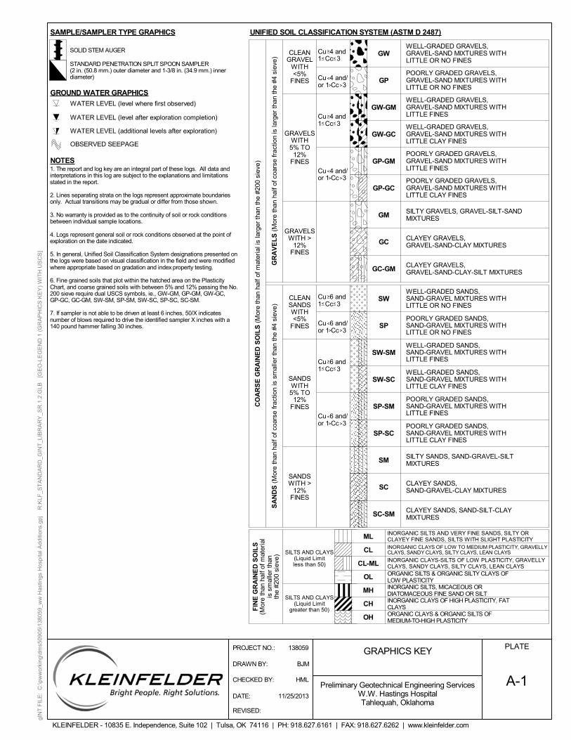
1. The report and log key are an integral part of these logs. All data andinterpretations in this log are subject to the explanations and limitationsstated in the report.
2. Lines separating strata on the logs represent approximate boundariesonly. Actual transitions may be gradual or differ from those shown.
3. No warranty is provided as to the continuity of soil or rock conditionsbetween individual sample locations.
4. Logs represent general soil or rock conditions observed at the point ofexploration on the date indicated.
5. In general, Unified Soil Classification System designations presented onthe logs were based on visual classification in the field and were modifiedwhere appropriate based on gradation and index property testing.
6. Fine grained soils that plot within the hatched area on the PlasticityChart, and coarse grained soils with between 5% and 12% passing the No.200 sieve require dual USCS symbols, ie., GW-GM, GP-GM, GW-GC,GP-GC, GC-GM, SW-SM, SP-SM, SW-SC, SP-SC, SC-SM.
7. If sampler is not able to be driven at least 6 inches, 50/X indicatesnumber of blows required to drive the identified sampler X inches with a140 pound hammer falling 30 inches.
_
SILTY SANDS, SAND-GRAVEL-SILTMIXTURES
CLAYEY SANDS,SAND-GRAVEL-CLAY MIXTURES
SW-SM
CLAYEY SANDS, SAND-SILT-CLAYMIXTURES
CL
CL-ML
>
<
<
Cu 4 and1 Cc 3
< _
ORGANIC SILTS & ORGANIC SILTY CLAYS OFLOW PLASTICITY
SILTS AND CLAYS(Liquid Limitless than 50)
SILTS AND CLAYS(Liquid Limit
greater than 50)
WELL-GRADED SANDS,SAND-GRAVEL MIXTURES WITHLITTLE OR NO FINES
POORLY GRADED SANDS,SAND-GRAVEL MIXTURES WITHLITTLE OR NO FINES
MH
OH
ML
GC-GM
CO
AR
SE
GR
AIN
ED
SO
ILS
(M
ore
than
hal
f of m
ater
ial i
s la
rger
than
the
#200
sie
ve)
SAMPLE/SAMPLER TYPE GRAPHICS UNIFIED SOIL CLASSIFICATION SYSTEM (ASTM D 2487)
<
Cu 6 and1 Cc 3
GP-GM
GP-GC
_
_ _<
>
<
<
>
SP
SP-SM
SP-SC
SM
SC
< _<
>_
GM
GC
GW
GP
GW-GM
GW-GC
_ _
_
INORGANIC CLAYS OF LOW TO MEDIUM PLASTICITY, GRAVELLYCLAYS, SANDY CLAYS, SILTY CLAYS, LEAN CLAYS
GRAPHICS KEY
<
>
<
<
>
CLEANSANDSWITH<5%
FINES
GR
AV
EL
S (
Mor
e th
an h
alf o
f coa
rse
frac
tion
is la
rger
than
the
#4 s
ieve
)
Cu 6 and/or 1 Cc 3
Cu 6 and/or 1 Cc 3
>
Cu 6 and1 Cc 3
SC-SM
WELL-GRADED GRAVELS,GRAVEL-SAND MIXTURES WITHLITTLE OR NO FINES
POORLY GRADED GRAVELS,GRAVEL-SAND MIXTURES WITHLITTLE OR NO FINES
WELL-GRADED GRAVELS,GRAVEL-SAND MIXTURES WITHLITTLE FINES
WELL-GRADED GRAVELS,GRAVEL-SAND MIXTURES WITHLITTLE CLAY FINES
POORLY GRADED GRAVELS,GRAVEL-SAND MIXTURES WITHLITTLE FINES
POORLY GRADED GRAVELS,GRAVEL-SAND MIXTURES WITHLITTLE CLAY FINES
SILTY GRAVELS, GRAVEL-SILT-SANDMIXTURES
CLAYEY GRAVELS,GRAVEL-SAND-CLAY-SILT MIXTURES
WELL-GRADED SANDS,SAND-GRAVEL MIXTURES WITHLITTLE CLAY FINES
POORLY GRADED SANDS,SAND-GRAVEL MIXTURES WITHLITTLE CLAY FINES
SW
SW-SC
POORLY GRADED SANDS,SAND-GRAVEL MIXTURES WITHLITTLE FINES
Cu 4 and/or 1 Cc 3>
>
FIN
E G
RA
INE
D S
OIL
S(M
ore
than
hal
f of m
ater
ial
is s
mal
ler
than
the
#200
sie
ve)
INORGANIC SILTS AND VERY FINE SANDS, SILTY ORCLAYEY FINE SANDS, SILTS WITH SLIGHT PLASTICITY
ORGANIC CLAYS & ORGANIC SILTS OFMEDIUM-TO-HIGH PLASTICITY
INORGANIC CLAYS OF HIGH PLASTICITY, FATCLAYS
INORGANIC SILTS, MICACEOUS ORDIATOMACEOUS FINE SAND OR SILT
INORGANIC CLAYS-SILTS OF LOW PLASTICITY, GRAVELLYCLAYS, SANDY CLAYS, SILTY CLAYS, LEAN CLAYS
SANDSWITH5% TO
12%FINES
SANDSWITH >
12%FINES
SA
ND
S (
Mor
e th
an h
alf o
f coa
rse
frac
tion
is s
mal
ler
than
the
#4 s
ieve
)
WELL-GRADED SANDS,SAND-GRAVEL MIXTURES WITHLITTLE FINES
Cu 4 and/or 1 Cc 3>
CLEANGRAVEL
WITH<5%
FINES
GRAVELSWITH5% TO
12%FINES
OL
CH
CLAYEY GRAVELS,GRAVEL-SAND-CLAY MIXTURES
GRAVELSWITH >
12%FINES
>
Cu 4 and1 Cc 3
>_
_
SOLID STEM AUGER
STANDARD PENETRATION SPLIT SPOON SAMPLER(2 in. (50.8 mm.) outer diameter and 1-3/8 in. (34.9 mm.) innerdiameter)
GROUND WATER GRAPHICS
OBSERVED SEEPAGE
WATER LEVEL (level after exploration completion)
WATER LEVEL (level where first observed)
WATER LEVEL (additional levels after exploration)
NOTES
PROJECT NO.: 138059
DRAWN BY: BJM
CHECKED BY: HML
DATE: 11/25/2013
REVISED:
gIN
T F
ILE
: C
:\pw
wor
king
\dm
s509
05\1
380
59_w
w H
astin
gs H
ospi
tal A
dditi
ons.
gpj
R:K
LF_S
TA
ND
AR
D_G
INT
_LIB
RA
RY
_SR
.1.2
.GLB
[G
EO
-LE
GE
ND
1 (
GR
AP
HIC
S K
EY
) W
ITH
US
CS
]

(# blows/ft)(# blows/ft)(# blows/ft)
PLATE
A-2Preliminary Geotechnical Engineering ServicesW.W. Hastings HospitalTahlequah, Oklahoma
KLEINFELDER - 10835 E. Independence, Suite 102 | Tulsa, OK 74116 | PH: 918.627.6161 | FAX: 918.627.6262 | www.kleinfelder.com
less than 1/4-in. thick, note thickness
> 8000
Firm
Hard
Very Hard
Non-plastic
Low (L)
Medium (M)
High (H)
NOTE: AFTER TERZAGHI AND PECK, 1948
Crumbles or breaks with considerable
Weakly
Moderately
Strongly
FIELD TEST
finger pressure
finger pressure
Will not crumble or break with finger pressure
DESCRIPTION
Crumbles or breaks with handling or slight
0 - 15(%)
RELATIVEDENSITYSAMPLER
<4
or thread cannot be formed when drier than the
any water content.
The thread can barely be rolled and the lump
when drier than the plastic limit
FIELD TEST
Absence of moisture, dusty, dry to the touch
SubangularRounded Angular
CRITERIA
Very Soft
Soft
Subrounded
Gravel
Sand
Fines
Thumb will penetrate soil more than 1 in. (25 mm.)
Wet
DESCRIPTION
fine
coarse
fine
#10 - #4
GRAINSIZE
>12 in. (304.8 mm.)
3/4 -3 in. (19 - 76.2 mm.)
0.19 - 0.75 in. (4.8 - 19 mm.)
SOIL DESCRIPTION KEY
FIELD TESTDESCRIPTION
plastic limit.
the plastic limit. The lump or thread crumbles
limit. The lump or thread can be formed without
Same color and appearance throughout
DESCRIPTION
Stratified
Laminated
Fissured
Slickensided
Inclusion of small pockets of different soils, such as small lenses
Blocky
Lensed
Homogeneous
CRITERIA
Alternating layers of varying material or color with the layer
0.0029 - 0.017 in. (0.07 - 0.43 mm.)
0.017 - 0.079 in. (0.43 - 2 mm.)
to reach the plastic limit. The thread can be
DESCRIPTION
None
Strong
Rounded
DESCRIPTION
Cobbles
Thumbnail will not indent soil
Thumb will penetrate soil about 1 in. (25 mm.)
CRITERIA
No visible reaction
Some reaction, with bubbles forming slowly
Violent reaction, with bubbles forming immediately
Weak
0.079 - 0.19 in. (2 - 4.9 mm.)
SPT-N60
Thumb will not indent soil but readily indented with thumbnail
Very DenseDense
Medium Dense
FIELD TEST
NP
< 30
> 50
<0.0029 in. (<0.07 mm.)
rerolled several times after reaching the plastic
SubroundedParticles have smoothly curved sides and no edges
Particles have nearly plane sides but havewell-rounded corners and edges
Particles are similar to angular description but have
of sand scattered through a mass of clay; note thickness
Thumb will indent soil about 1/4-in. (6 mm.)
to fracturing
Alternating layers of varying material or color with layers
Angular
Subangular
Boulders
LL
30 - 50
Particles have sharp edges and relatively planesides with unpolished surfaces
rounded edges
at least 1/4-in. thick, note thickness
CONSISTENCYUNCONFINED
COMPRESSIVESTRENGTH (Qu)(psf)
medium
Loose
Very Loose
DENSITY
1000 - 2000
DESCRIPTION
Dry
Moist
is required to reach the plastic limit.The thread cannot be rerolled after reaching
The thread is easy to roll and not much time
12- 35
5 - 12
A 1/8-in. (3 mm.) thread cannot be rolled at
5 - 15
15 - 4040 - 70
85 - 10065 - 8535 - 65
15 - 35
>70
Damp but no visible water
Visible free water, usually soil is below water table
Cohesive soil that can be broken down into small angular
crumbling when drier than the plastic limit
lumps which resist further breakdown
Fracture planes appear polished or glossy, sometimes striated
Breaks along definite planes of fracture with little resistance
APPARENT
>60
<5
35 - 60
SAMPLERMODIFIED CA CALIFORNIA
<4
4 - 10
10 - 3030 - 50
>50
< 1000
2000 < 4000
4000 < 8000
It takes considerable time rolling and kneading
coarse
ABBR
R
YGYG
BG
RedYellow Red
YellowGreen Yellow
GreenBlue Green
BluePurple Blue
PurpleRed Purple
NAME
YR
BPBP
RP
#40 - #10
#200 - #10
Passing #200
3 - 12 in. (76.2 - 304.8 mm.)
3/4 -3 in. (19 - 76.2 mm.)
#4 - 3/4 in. (#4 - 19 mm.)
SIEVESIZE
>12 in. (304.8 mm.)
3 - 12 in. (76.2 - 304.8 mm.)
Pea-sized to thumb-sized
Thumb-sized to fist-sized
Larger than basketball-sized
Fist-sized to basketball-sized
Flour-sized and smaller
Rock salt-sized to pea-sizedSugar-sized to rock salt-sized
Flour-sized to sugar-sized
SIZEAPPROXIMATE
CONSISTENCY - FINE-GRAINED SOIL
MOISTURE CONTENT
APPARENT / RELATIVE DENSITY - COARSE-GRAINED SOIL
CEMENTATION
PLASTICITY
REACTION WITH HYDROCHLORIC ACID
GRAIN SIZE
ANGULARITY
STRUCTURE
Munsell Color
PROJECT NO.: 138059
DRAWN BY: BJM
CHECKED BY: HML
DATE: 11/25/2013
REVISED:
gIN
T F
ILE
: C
:\pw
wor
king
\dm
s509
05\1
380
59_w
w H
astin
gs H
ospi
tal A
dditi
ons.
gpj
R:K
LF_S
TA
ND
AR
D_G
INT
_LIB
RA
RY
_SR
.1.2
.GLB
[G
EO
-LE
GE
ND
2 (
SO
IL D
ES
CR
IPT
ION
KE
Y)]