new trends in rock mass characterisation for designing
TRANSCRIPT

ACTA GEOTECHNICA SLOVENICA, 2005/2 39.
NEW TRENDS IN ROCK MASS CHARACTER-ISATION FOR DESIGNING GEOTECHNICAL STRUCTURES
DRAGO OCEPEK
About the author
Drago OcepekGeoinženiring d.o.o.Dimičeva 14, 1000 Ljubljana, SlovenijaE-mail: [email protected]
Abstract
The investigation on designing supporting measures for geotechnical structures consists of the proper selection of the input data for the stress – strain analysis of the excava-tion process and the selection of retaining measures. In the preliminary phase of investigation the area must be geologically mapped in detail, and discontinuities precisely measured, boreholes and their “in situ” tests listed and samples for laboratory examinations taken. The new method allows rock mass classification for different rock quality, from soft rocks to mixed rock masses, as well as determination of the geological strength index GSI. The limits for using the suggested method are persistent discontinuities in rock mass which lead to translation or rotation failure mechanisms, either in a single plane or as a wedge. In all cases where discontinuities play a signifi-cant role, the rock mass structure must be considered and kinematical analyses performed. In other circumstances, a rock may be uniform and reasonably isotropic due to the geometry of discontinuities and their mutual intersections. The value range of GSI is first determined in the begin-ning of investigation and later in the excavation phase by considering the disturbance factor D, which expresses disturbances caused by excavation methods and rock mass relaxation. The strength and deformability parameters of rocks of different quality are determined by the generalized Hoek-Brown failure criterion and applied to shallow and deep tunnels or slopes. Before the start of excavations work and after establishing the retaining measures, the analysis results are checked by monitoring. New methods include the determination of post peak strength parameters of rock mass after relaxation, and routine measurements. The newest measurement system however allows direct read-ings of displacements of the rock mass in both the elastic and post-peak states. With back analyses we determine the
softening behavior of the rock mass and a possible need for increasing retaining measures. Such a design method enables the optimization of retaining measures and the reduction of investment costs.
Keywords
geological strength index – GSI, simulation of a triaxial large scale »in situ« test, numerical modeling, retaining measures, rock reinforcement, monitoring, back analy-ses, strain softening, rock mass relaxation
1 INTRODUCTION
To determine the characteristics of rock mass the investigation and analysis are first undertaken in the main project phase. The purpose of the investigation and analysis is to determine the input parameters for a numerical analysis which are needed to specify support-ing and retaining measures for the excavation of under-ground structures, or for cutting slopes in front of tunnel portals, and later for their correct dimensioning and installment into the geological structure of the build-ing site. The analyses results are needed to determine supporting and retaining measures that can even be geotechnical structures in their strongest version. This is followed by further investigation of rock mass character-istics in order to adapt to geological and geomechanical changes during the excavation process.
During the design process of geotechical structures, underground structures or deep caverns, the input parameters for the stress-strain analysis of the excava-tion process must be correctly determined. In the preliminary phase of the investigation, the area must be geologically mapped in detail, discontinuities precisely measured, boreholes and “in situ” investigations listed, and samples for laboratory examinations taken. First of all we must determine the possibility of failure mecha-nisms caused by mutual intersections of discontinuities

ACTA GEOTECHNICA SLOVENICA, 2005/2 40.
within rock mass. In all cases where discontinuities play a significant role, the rock mass structure must be considered and kinematical analyses performed. In other circumstances a rock may be uniform and reasonably isotropic. If the difference between the properties of rock mass and the discontinuities are small, and when the failure does not depend on anisotropy, we can use the modern rock mass classification to determine the value range of the geological strength index GSI (Marinos & Hoek, 2000, 2001) [5]. This classification is comparable and correlated to Bieniawski [2] classification, with the determination of the RMR and RMRTBM values and the Austrian rock mass classification (ÖE NORM B 2003). The main difference is that this classification enables direct determination of stress strain parameters for different types of rock masses, from weathered to compact, blocky to disintegrated, mixed and tectoni-cally damaged, or sheared soft rock masses. When the value range of the geological strength index GSI has been established, the material constants of weathered and compact rocks can be determined considering the rock mass disturbance factor D, influenced by excava-tion methods and quality. With the use of generalized Hoek-Brown failure criterion (Hoek, Carranza-Torres & Corkum, 2002) [4], the strength and deformability parameters of different quality rock masses are deter-mined.
In the investigation phase during the excavation process, observations of freshly excavated surfaces are conducted, and the rock mass is additionally geologically mapped. Precise measurements of discontinuities must be taken and the geological strength index GSI reestablished. Several new samples for additional laboratory exami-nations must be taken. During slope excavations, a global spatial rock mass stability analysis is made, which is based on the statistically determined common discontinuity cross-section system with considering the anticipated seismic acceleration (EC – 8). In the under-ground areas the possibility of wedge failure of walls and roof must be examined. An exact stress – strain analysis of each excavation phase must be conducted and inbuilt support measures considered. Stability is checked during the excavation phases and in the final phase. This way of planning enables the optimizing of retaining measures, which reduces the investment costs.
During the installation of supporting structures, the analysis is checked by using the established technical observation and monitoring procedure, determined in the project. The anchor force measurements, observa-tions of geodetic points and the measurements of water movements and levels in inclinometers and piezometers are also included. The newest measurements include the determination of rock mass post peak parameters after
relaxation that takes place after the excavation. Measure-ments are taken with the SMART (Stretch Measurement for Assessment of Reinforcement Tension) and MPBX (Multi-Point Borehole Extensometer) systems after the support measures have been implemented [3]. Both instruments provide direct readings of displacements of the rock mass in both the elastic and strain softening regimes. With back analysis we can later determine the softening behavior of the rock mass and eventual need for additional supporting or retaining measures. Moni-toring must be continued while the structure is in use.
2 GEOLOGICAL GEOMECHANICAL INVESTIGATIONS AND ANALYSES IN DESIGN
The investigation work needed for designing a geotech-nical structure is based on different methods for estab-lishing physical characteristics of rocks, soft rocks and soils, and on the correct selection of input parameters for the numerical stress strain analyses of the excavation and retaining measures.
2.1 GEOLOGICAL MAPPING AND GEOPHYSICAL MEASUREMENTS
In the preliminary phase of the investigation, the building area must be geologically mapped in detail and all outcrops charted needed for exact measure-ments of discontinuities found. We must be aware that examination bore holes provide point information only, and therefore special effort must be taken to chart outcrops in detail. In addition, trial tits are used to take measurements of layers and discontinuities, and the surface state of rock masses is described in detail. If the area of investigation is covered by a thick disintegrated layer, geophysical tests are also used (geoelectrical and seismic measurements). But preferably, a pilot tunnel is constructed by considering detailed charting, »in situ« measurements and laboratory samples.
2.2 EXAMINATION BORE HOLES AND »IN SITU« MEASUREMENTS
During boring, a double core sampler with diamond tips and water cooling must be used. When boring soft rocks, heavy polymer suspensions must be used. During this phase, pressiometer measurements and dilatometer measurements must be taken in hard and soft rocks and samples provided for laboratory testing. We must carefully register the depth of underground water,
D. OCEPEK: NEW TRENDS IN ROCK MASS CHARACTERISATION FOR DESIGNING GEOTECHNICAL STRUCTURES

ACTA GEOTECHNICA SLOVENICA, 2005/2 41.
especially if it is linked to discontinuities. It is highly advisable, that pouring tests and measurements using pressured water (WPT) are taken. If bore holes are made in proper distances, it is advisable to take »cross hole« measurements (geophones arranged in two bore holes, in which case triggering of seismic waves provides a high quality transcript), or at least, combine the »down hole« measurements (geophones arranged in a single bore hole) with seismic profiling (geophones arranged on the surface), and conduct a seismic tomography.
With respect to surface mapping, it is necessary to use the rock mass classification according to Bieniawski when the cores are registered. This includes the estab-lishment of the RMR value (Bieniawski, 1989) and the determination of the value range of the geological strength index GSI (Marinos & Hoek, 2000 - 2005)[4, 5, 6, 7 and 8].
2.3 LABORATORY EXAMINATIONS
In hard compact rocks it is necessary to conduct uniaxial compression tests at least; if possible, this includes the determination of deformability parameters (elasticity modulus and Poisson coefficient). In disintegrated rocks it is recommended to determine the point load index normally and perpendicularly to layers. In soft rocks, direct and torsion shear tests and possible triaxial shear tests must be made. In tectonically disturbed or otherwise softened zones of soft rocks, edometric exami-nations must be conducted and permeability coefficient determined.
2.4 MINERALOGICAL PETROGRAPHIC EXAMINATIONS
It is of vital importance to determine the mineralogical structure and texture of the rock. For this purpose, mineralogical petrographic examinations are conducted together with the geomechanical laboratory examina-tions (this can be done on the same samples). It is advisable to conduct microscopic and X-ray analyses as well. The results are used for calculating the material constants of rocks, from alterated to compact ones.
3 ANALYSES FOR THEDETERMINATION OF ROCK MASS CHARACTERISTICS
3.1 THE GEOLOGICAL STRENGTHINDEX GSI AND THE GENERALIZED HOEK-BROWN FAILURE CRITERION
Based on the generalized Hoek-Brown failure criterion (Hoek, Carranza, Torres & Corkum, 2002) with the application to shallow or deep tunnels and slopes, the strength and deformability parameters of different rock quality can be determined for slopes (portal slopes and geotechnical constructions) as well [4]. The parameters are subsequently used for geostatical analyses of stress strain criteria for the excavation and retaining measures. In all cases where discontinuities play a significant role, the rock mass structure must be considered and kine-matical analyses performed.
The input data for the calculation of the failure criterion are acquired by detailed geological engineering mapping including discontinuity measurements, determination of the geological strength index–GSI and uniaxial compres-sive strength, or by pairs of effective stresses at failure in triaxial tests.
The geological strength index was introduced by Hoek, Kaiser and Bawden (1995). This system enables a procedure for determining the reduction of rock mass strength in different geological conditions. The most recent modifications with respect to the expansion of rock mass of mixed composition were done by Hoek, Marinos and Benissi in 1998, and Marions and Hoek in 2000 and 2001.
The geological strength index [5] is based on lithological composition, structure and surface conditions of the rock mass discontinuities. Combining two basic param-eters of geological processes, i.e. blocks of rock mass and the surface condition of discontinuities, it reflects the main conditions of geological formation. When chart-ing the excavation, it is determined by comparing the structure shown by figures in special tables. It must be especially stressed that without detailed measurements of discontinuities (spatial orientation, number of discon-tinuity systems, size of blocks, and surface conditions of discontinuities, such as roughness, filling and disintegra-tion level, and tectonic disturbance), the comparison is not possible by using tables. It is better to determine the value range than the exact value.
D. OCEPEK: NEW TRENDS IN ROCK MASS CHARACTERISATION FOR DESIGNING GEOTECHNICAL STRUCTURES
ACTA GEOTECHNICA SLOVENICA, 2005/2 42.
The assessment of the geological strength index is impeded by disturbances caused by blasting. If possible, undisturbed areas must be used for assessment. In the new classification (Marinos & Hoek, 2001), which is also used in the special program package RocLab (Rocscience 2002) for the calculation of the generalized failure criterion, the table for determining the general-ized failure criterion of the rock mass D is specially presented [4, 5]. For rock masses of higher quality(GSI > 25) the GSI value can be compared to the last version of Bieniawski ‘s classification (RMR, 1989) in the following correlation:
GSI = RMR89' - 5 (1)
In this case, when determining RMR, the relation of underground water points must be set to 15 (completely dry), and the condition of spatial orientation of discon-tinuities to 0 (a very favorable position). But it is always better to determine the GSI directly by considering the genesis of rock mass.
When establishing rock mass characteristics accord-ing to the Hoek–Brown system, it is most important to reduce the material constants σci and mi from their »intact – i« laboratory values to the acquired values of fractured rock mass. This is achieved with the geological strength index (GSI). The values of mi constants, which were corrected from the initial classification based on several laboratory tests and experiences of engineering geologists, are presented in a special table (Hoek & Marinos, 2000), [5]. The determination of structure, texture and crystal structure of rocks based on mineral-ogical petrographic examinations is of great help in this determination of rock mass fabric.
After determining the value of GSI, the parameters [4] for the evaluation of strength characteristics of rock mass can be calculated:
m m eb i
GSID=
−−
10028 14 , (2)
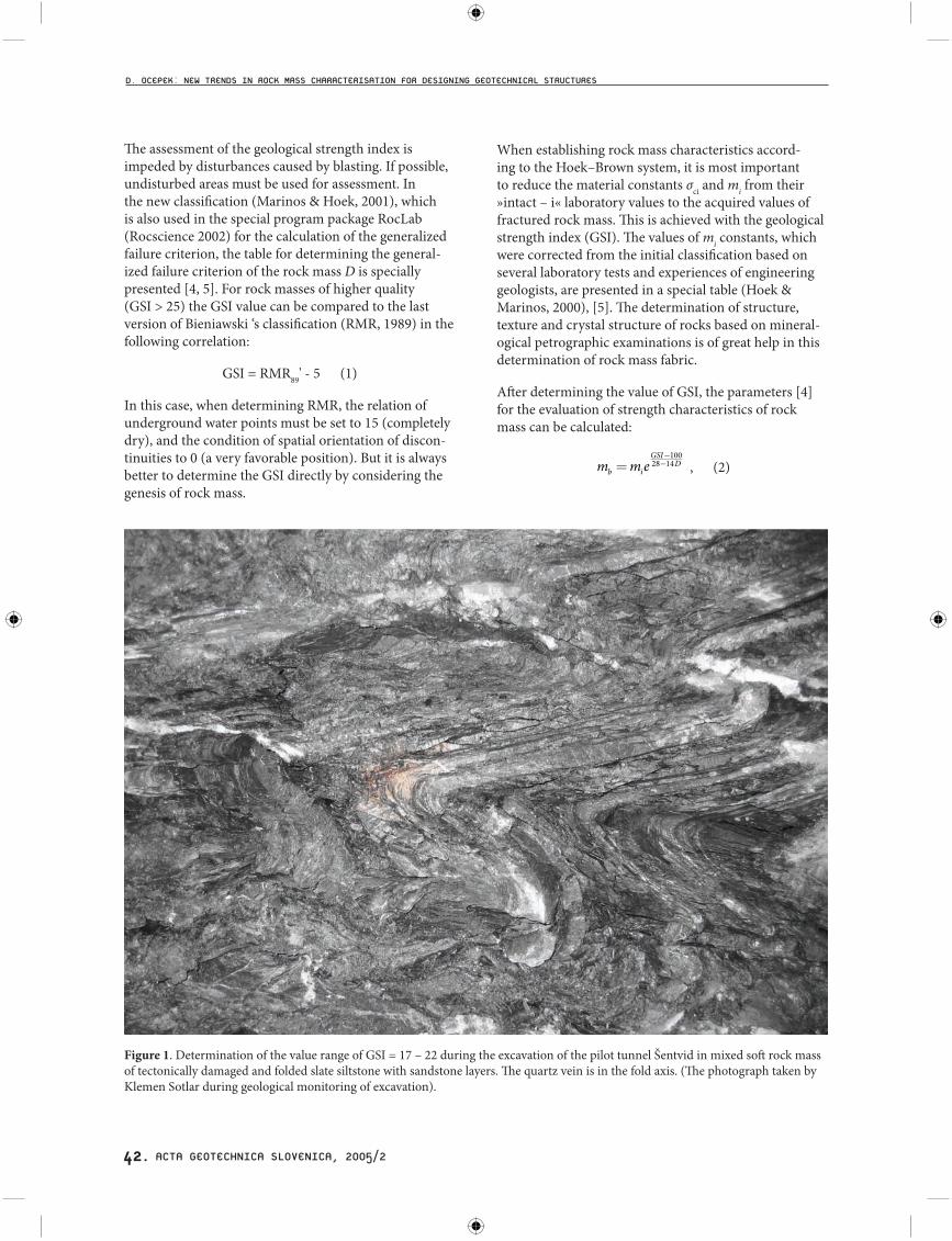
Figure 1. Determination of the value range of GSI = 17 – 22 during the excavation of the pilot tunnel Šentvid in mixed soft rock mass of tectonically damaged and folded slate siltstone with sandstone layers. The quartz vein is in the fold axis. (The photograph taken by Klemen Sotlar during geological monitoring of excavation).
D. OCEPEK: NEW TRENDS IN ROCK MASS CHARACTERISATION FOR DESIGNING GEOTECHNICAL STRUCTURES

ACTA GEOTECHNICA SLOVENICA, 2005/2 43.
where:
- mb represents the value of the Hoek-Brown constant m for the rock mass,
- mi represents a constant, dependent on the crystal structure,
- D represents the rock mass disturbance factor.
The latest change published and also included into the RocLab program, is based on the revised equations for determining the s and a constants which now include the rock mass disturbance factor D:
s eGSI
D=−
−100
9 3 (3)
a e eGSI= + −( )− −12
16
15 20 3 (4)
Similar to Bieniawski’s classification where the assess-ment of the elasticity modulus is based on the RMR value (Serafim & Pereira, 1983, use back analyses of deformation when laying foundations of high dams in rock masses of higher quality), the equation for rock masses of lower quality is modified after the results have been obtained of practical observations and by back analyses of the behavior of such rock masses. Eq. (4) also includes the factor of the rock mass disturbance that occurred due to deformations caused by excavation (mechanical excavation or blasting) and strain relief:
E D ˆ 10m
GSI 1040ci
= −( )−
1 2 100 (GPa) (5)
In Eq. [5] GSI replaces RMR in such a way that Em module in progressively reduced when the value of σci < 100. This reduction is based on the fact that deformations of higher quality rock masses depend on discontinuities, whilst in the rock masses of lower qual-ity they are part of the common deformational process of the intact rock mass portions.
For jointed rock masses, the equation of the generalized failure criterion was eventually developed [4]:
′ ′ ′⎛
⎝
⎜⎜⎜⎜⎜⎜⎜⎜
⎞
⎠
⎟⎟⎟⎟⎟⎟⎟⎟⎟ˆ ˆ ˆ m ˆ
ˆ sci b ci
a
1 33= + + (6)
where σ1' and σ3' represent the maximum and minimum effective stress at failure;
- s and a are constants, dependent on the rock mass characteristics (determination is based on the geolo-gical strength index GSI, when s = 1 we deal with the analysis of intact undisturbed rock mass samples),
- σci represents uniaxial compressive strength of intact pieces of the rock mass,
- mb is the Hoek–Brown constant (m) value for the rock mass.
For each type of the rock mass and each strain range, we must determine the appropriate angle of internal friction and cohesion in relation to the Mohr–Coulomb failure criterion. This is done with fitting a curve of nonlinear Hoek–Brown relation (Eq. 6) to average linear proportion, in the value range of minor principal strains σt < σ3 < σ3max. The appropriate angle of internal friction and cohesion is calculated according to »the smallest squares« method (Hoek, E., Carranza – Torres, C., Corkum, B., 2002), [4].
The values of ϕi' and ci', which are acquired by the analy-sis of data pairs from triaxial shear tests, are very sensi-tive to the range of minor effective main stress σ3' which is used for generating the simulated results of large scale triaxial test. Therefore, two specific applications are given for their determination, based on numerous measurements and back analyses for tunnels and slopes.
- The equation for shallow and deep tunnels is:′′
=′⎛
⎝⎜⎜⎜
⎞
⎠⎟⎟⎟⎟
−σσ
σγ
3 0 470 94
max.
.cm
cm
H, (7)
where γ represents the specific weight of the rock mass, and H the depth of the tunnel below the surface.
- The equation for slope:′′
=′⎛
⎝⎜⎜⎜
⎞
⎠⎟⎟⎟⎟
−σσ
σγ
3 0 720 91
max.
.cm
cm
H , (8)
where γ represents the specific weight of the rock mass and H the height of the slope.
In Fig. 2, the simulation of a triaxial large scale »in situ« test is presented. It includes twelve pairs of effective stresses at failure of the intact samples of disintegrated tectonically damaged rock mass of Carboniferous-Perm-ian soft rocks, exposed to the cyclic effects of suction and dehydration during ancient landslides and subsequent extensive excavations. The samples were acquired during research borings accompanied by »in situ« pressiometer and »down hole« measurements. These data are needed for the project changes made by numerical modeling to apply the retaining measures to cut slopes of the Blagovica–Kompolje motorway section by using deeply founded, multiply anchored supporting geotechnical structures.
σ
D. OCEPEK: NEW TRENDS IN ROCK MASS CHARACTERISATION FOR DESIGNING GEOTECHNICAL STRUCTURES
σ σ σ σσ

ACTA GEOTECHNICA SLOVENICA, 2005/2 44.
It is thus possible to observe the structure, texture, mixed composition, and the level of tectonic distur-bance, i.e. anisotropic characteristics of the rock mass [12]. It must be noted that the cohesion strength is growing with depth. Therefore, corrections can eventu-ally be made when conducting numerical back analyses in relation to proportion of measured deformations. For the Carboniferous-Permian mixed soft rock mass these are most corresponding (≥ 90 %) when material model-ing with kinematics hardening is used. For this purpose, a modulus calculated according to the generalized Hoek–Brown criterion, can be used as the referential elasticity modulus. The modulus of elasticity determined by pressiometer test [6, 7, and 8] was used.
3.2 STRESS–STRAIN ANALYSES OF EXCAVATION AND RETAINING MEASURES
For mathematical modeling, advancement of the rock mass failure must be established by determining post
Figure 2. The simulation of a large scale triaxial »in situ« test by using twelve pairs of effective stresses to the failure of intact samples in a triaxial shear apparatus [11]. The test was corrected by the GSI and mi values determined during the excavation for anchored retaining walls. The rock mass disturbance factor D = 0 (marginal disturbances) due to the excavation in mixed soft rocks.
peak strength or post failure parameters. With some models, Hoek-Brown empirical failure criterion is treated as a plastic flow criterion in which case the analyses are made by using the plasticity theory (Pan in Hudson, 1988). There are no special rules defined for this, but there are basic guidelines acquired by experience with numerical analyses of different practical problems that suggest basic post failure parameters.
For the rock mass of very high quality, like massive gran-ite or quartzite, elastic brittle behavior can be presumed (Hoek, Kaiser & Bawden, 1995). When the strength of the rock mass is surpassed, the strength suddenly decreases and the number of crushed fragments of rock mass increases substantially. Deformational parameters of the rock mass are virtually quartered and the dilatation angel (ψ) is equivalent to a quarter of the internal friction angle. For rock mass of average quality, authors recommend the determination of post failure parameters by reducing the GSI index to a lower value that determines disturbed rock mass, which corresponds to the characteristics of weakening of material with
D. OCEPEK: NEW TRENDS IN ROCK MASS CHARACTERISATION FOR DESIGNING GEOTECHNICAL STRUCTURES

ACTA GEOTECHNICA SLOVENICA, 2005/2 45.
growing deformations and the dilatation angle value of one eighth of the internal friction angle. Analyses of the advancement of failure in rock masses of very poor qual-ity show that these behave as ideal elastoplastic material. This means that after peak strength is achieved, defor-mations continue with constant stresses without spatial changes (distortions). The dilatation angle equals zero, and final deformation parameters remain unchanged.
Today, numerous constitutive models of different authors are included in computer programs and corresponding input parameters must be entered for them. When designing underground structures, Mohr–Coulomb constitutive model and the material model of softening behavior are most commonly used. Its input parameters can be determined with the use of standard field and laboratory rock and soil tests. For soft rock masses, deformations are more precisely modeled using a material model with kinematics hardening (it is included in the program Plaxis – Hardening Soil model) [10].
The results of analyses are satisfying and suitable for designing underground and geotechnical structures in changeable geological and geomechanical conditions. Taking measurements during monitoring and compar-ing predicted and measured deformations provide sufficient proof.
The calculation of stress-strain changes is mostly affected by the Poisson’s coefficient ν and the elasticity module E that is almost insignificant in the calculation of stability. In the calculation of the safety factor, the internal fric-tion angle and cohesion plays the most significant role in both drained and undrained conditions. In stability analyses according to FEM stress-strain analyses in undrained conditions, changes of pore pressures must be considered, as these are usually most significant (suction process).
4 STRAIN SOFTENING BEHAVIOUR OF ROCK MASSES
Strain softening and rock mass relaxation after the excavation can be successfully modeled using the generalized Hoek–Brown failure criterion (GHB). In this case, the rock mass parameters in the elasticity range and post peak (residual value) [3] parameters must be determined. Material constants established on the basis of GHB are used to determine peak values, and strain softening is best determined by using back analyses, in which case back numerical modeling of deformations
must be performed in different phases of the excavation and additional retaining measures must be conducted. When calculated deformations satisfactorily correspond to measured deformations (monitoring with special measurement equipment) in both ranges, it is possible to determine an empirical relation for the range of rock mass strain softening with correct degradation of Hoek–Brown parameters. Subsequently, it is possible to construct the relaxation curves and determine the soft-ening parameters. Some numerical modeling programs already include constitutive models based on the gener-alized Hoek–Brown failure criterion. Such programs are Phase 2D (Rocscience) and FLAC3D [9].
In Fig. 3 we demonstrate that the true nature of strain-softening response is not known for large field-scale rock masses, but the material softening can be simulated by specifying the Hoek-Brown mechanical properties change and hence the reduction of the overall material strength [3].
Figure 3. Strain-softening response for large field-scale rock masses
When we create a staged numerical model of tunnel excavation in which the modulus of excavation mate-rial is successively reduced, we must first construct a “ground reaction curve”. This is a plot of the boundary displacement (convergence) versus reactive pressure. We can then determine the amount of deformation which is to be allowed prior to support installation. This can be done by numerical modeling or by closed form and empirical formulas or even by observation and experi-ence (NATM). Finally, we use the ground reaction curve and the tunnel convergence to determine the required material modulus that gives the desired convergence at support installation. It is then possible to create a staged excavation, with one stage used for the softening rate and the next stage used for the support installation.
D. OCEPEK: NEW TRENDS IN ROCK MASS CHARACTERISATION FOR DESIGNING GEOTECHNICAL STRUCTURES

ACTA GEOTECHNICA SLOVENICA, 2005/2 46.
In continuation a case of determining softening parame-ters (λ and r: Panet–Chern curves) is presented using the Chern curve calculation (Kavvadas M., 2005, Ljubljana Workshop, IZS,) [13].
Figure 4. The diagram of deconfinement ratio λ, referring to the distance of rock mass relaxation from the head of tunnel excavation, dependent on the relation of the initial and final rock mass module (E/E0) after relaxation. Parameters for the rock mass are: GSI = 12, σci = 10 MPa, σcm = 320 kPa,E0 = 350 MPa, ν = 0,3.
5 BACK ANALYSES OF EXCAVATION AND RETAINING MEASURES
The weak soft rock foundation of the designed structures within the area of the Trojane-Blagovica-Kompolje motorway section, which runs across extremely unstable slopes, consists of Carboniferous-Permian siltstones and clay stones with lenses of sandstone. A critical point of stability is conditioned by macro and microstructure of weak soft rock, being on one hand tectonically crushed and on the other hand displaced and weakened by wetting and drying cycles (suction-destructurisation) during past instabilities. The unload caused by the excavation for the foundation works and heavy rainfall during autumn activated a deep landslide in the building area of the Blagovica–Kompolje motorway section. The landslide was successfully stabilized with an anchored pile wall, the material exchange below the pile wall, and a special drainage system.
Experiences with landslide stabilization works resulted in a very careful design of retaining structures in the
Figure 5. Parametric back analyses based on the finite element method (the deformed grid realized by the Plaxis program, version 8.2) [10] using the material model with kinematics hardening for soft mixed rock mass of disintegrated and tectonically disturbed Carbon-iferous-Permian siltstones and clay stones with lenses of sandstone. Measured deformations on deeply laid supporting structures were precisely modeled.
D. OCEPEK: NEW TRENDS IN ROCK MASS CHARACTERISATION FOR DESIGNING GEOTECHNICAL STRUCTURES

ACTA GEOTECHNICA SLOVENICA, 2005/2 47.
unstable area on the Trojane–Blagovica motorway section. Four retaining structures were designed for the protection of the high slope consisting of Carboniferous-Permian tectonically damaged siltstones and clay stones with lenses of sandstone.
On the basis of detailed geotechnical investigations, a geotechnical model was constructed, which served, along with carefully selected input parameters [14], for the numerical analysis, the determination of pressure on the designed structures, and the determination of foun-
dation conditions of the designed construction works. In addition to inclinometers built into piles, inclinometers were also built into deep structure boreholes above and under the motorway layout to monitor the execution of construction works and their performance after comple-tion.
Fig. 5 shows back numerical analyses of the highest slope on the Trojane–Blagovica motorway section with designed retaining structures OZ – 15/16 (anchored walls) and PZ – 25 (anchored pile wall).
a)
b)
Figure 6. a) A bending moment in the pile wall without additional anchorage considering traffic load, b) horizontal displacement of the wall without anchorage of the pile wall.
D. OCEPEK: NEW TRENDS IN ROCK MASS CHARACTERISATION FOR DESIGNING GEOTECHNICAL STRUCTURES

ACTA GEOTECHNICA SLOVENICA, 2005/2 48.
Strength and deformability characteristics of mixed rock mass were acquired using a simulated large scale triaxial »in situ« test (see Fig. 2) based on the generalized Hoek–Brown failure criterion. In the final stage, an additional anchor was not installed after the excavation secured with retaining and supporting structures OZ-15/16, PZ-25. Traffic load was observed according to standards.
5 TECHNICAL OBSERVATION AND MONITORING
Technical observation and monitoring must be estab-lished after each excavation phase, as the majority of deformations occur partly during the excavation itself
Figure 7. Safety calculation without additional anchorage (presentation of a failure mechanism occurrence).
Figure 8. Presentation of the safety factor by stage analysis, and consideration of traffic load without additional anchorage of the pile wall.
Figure 9. Presentation of the safety factor by stage analysis, and consideration of traffic load with additional anchorage of the pile wall.
D. OCEPEK: NEW TRENDS IN ROCK MASS CHARACTERISATION FOR DESIGNING GEOTECHNICAL STRUCTURES

ACTA GEOTECHNICA SLOVENICA, 2005/2 49.
and partly after the construction of retaining structures. Today, multi-celled extensometers and force meters as well as stress–strain measuring cells are usually routinely built into anchors for taking measurements during the erection of underground structures. For measur-ing deformations and water levels, inclinometers and piezometers are integrated into specially constructed bore holes. If needed, they can be placed horizontally
as well. They are especially suitable for underground structures with low roofing.
New trends in monitoring [3] are directed especially towards the rationalization of retaining measures, and towards a more precise determination of rock mass characteristics. This includes the determination of post peak parameters after rock mass relaxation. In addition
PROPOSED DESIGN METHOD AND ROCK MASS CHARACTERIZATTION
D. OCEPEK: NEW TRENDS IN ROCK MASS CHARACTERISATION FOR DESIGNING GEOTECHNICAL STRUCTURES

ACTA GEOTECHNICA SLOVENICA, 2005/2 50.
to numerical analyses, a detailed determination is used in modern design of the geological strength index GSI on recently excavated surfaces, as well as numerical back modeling of measured deformations in the excavation phases. Subsequent retaining measures for rock mass stabilization are applied. Measurements must cover rock mass deformations in elastic and softening and relax-ation states. This is enabled by the integration of cable anchors and recently developed stretch meters for the assessment of reinforcement tensions (SMART), as well as by integration of multi-point borehole extensometers (MPBX) into boreholes of sufficient depth to cover rock mass softening and relaxation ranges.
It must be stressed, that during the construction of the tunnel “V Zideh” at the “Trbovlje–Izlake” road junction on the Vransko–Trojane motorway section, a similar technique of measurements was used for the rock mass elastic state at least. This was part of the research on anchor behavior in rock masses of low bearing strength (Likar, J. et all, 1998). Static and dynamic effects of the installed cable anchors equipped with simple meters (strain gauges) are also given for the loading effects obtained by blastings in the mines “RUZV”, and “Hrast-nik”. Strain measurements using the triaxial measure cells CSIRO were also conducted during the excavations [1].
6 CONCLUSION
It was established that in designing underground struc-tures, similarly to deeply cut slopes, and geotechnical structures a careful designer’s geological and geotechni-cal supervision of the execution is important in the planning phase, besides suitably executed geological and geomechanical research and geostatical analyses. An optimal placement of the design solution into the given geological environment can be achieved. Thus, the demanded safety levels based on planned technical observation and monitoring are assured during the execution of works, and after the completion of works a rational design method is proposed.
During the execution itself, a suitable solution must be given for each type of the geological structure. We must determine the possibility of failure mechanisms caused by mutual intersections of discontinuities within rock mass. If the difference between the properties of rock mass and the discontinuities are small, and when the failure does not depend on anisotropy, we can use a new classification for blocky and mixed hard and soft rocks, or even tectonically crushed and squeezed rock masses (Marinos & Hoek, 2005) [5, 6, 7, 8]. A modern
classification can be used in addition to the established rock classification according to Bieniawski (1989, in accordance with EC 7) [2], either indirectly (in correla-tion to Bieniawski’s classification – RMR) or preferably directly, using new methods (determination of geologi-cal strength index GSI).
Acquired parameters and the results of the laboratory examinations conducted in the planning phase or even during the execution of works itself are used for numeri-cal back analyses and determination of reaction curves, i. e. rock mass retaining measures.
After each excavation phase suitable technical observa-tion (monitoring) must be performed. This gives the possibility to compare predicted calculated shifts and measured shifts. If necessary, possible additional retain-ing measures must be implemented.
ACKNOWLEDGEMENTS
The article is based on the survey of the National program for motorway construction. The author would like to express his thanks to the Administrative Council of “DARS” for their approval to publish the data. The useful comments provided by Dr. Boštjan Pulko and Dr. Janko Logar of the University of Ljubljana, FGG, KMTal are gratefully acknowledged. The author is also grateful to project managers Ljubo Korpar of Gradis NG Maribor and Leon Gradnik of PNZ, Ljubljana, and to Pavle Saje, vice manager of Project 5 (Trojane), and Aljoša Brus, manager of Project 2 (Blagovica).
REFERENCES
[1] Bajželj, U., Likar, J., Žigman, F. (1995). Some proce-dures for installation of anchoring systems and the evaluation of capacity. Anchors in Theory and Practice, Widmann E., A. A. Balkema, Rotterdam, Brookfield, 189 – 196.
[2] Bienawski, Z. T. (1989). Engineering rock mass classifications. Wiley, New York.
[3] Crowder, J. J., Bawden, W. F. (2004). Review of Post-Peak Parameters and Behaviour of Rock Masses: Current Trends and Research. Rock News, October 2004, Lassonde Institute, University of Toronto, Toronto.
[4] Hoek, E., Carranza-Torres, C. T., and Corkum, B. (2002). Hoek–Brown failure criterion. 2002 ed. Proc. North American Rock Mechanics Society Meeting, Toronto, July 2002.
D. OCEPEK: NEW TRENDS IN ROCK MASS CHARACTERISATION FOR DESIGNING GEOTECHNICAL STRUCTURES

ACTA GEOTECHNICA SLOVENICA, 2005/2 51.
[5] Marinos, P., Hoek, E. (2000). GSI: A geologically friendly tool for rock mass strength estimation. International Conference on Geotechnical and Geological Engineering, Geoeng 2000, Melbourne, Technomic Publishing Company, Inc. U.S.A.,
1422 – 1440.[6] Hoek E., Marinos, P.G. (2000). Predicting tunnel
squeezing. Tunnels and tunnelling international, Part 1: November 2000, 45-51; Part 2: December 2000, 34-6.
[7] Hoek, E., Marinos, P.G, and Marinos, V.P. (2005). Characterisation and engineering properties of tectonically undisturbed but lithologically varied sedimentary rock masses. International Journal of Rock Mechanics & Mining Sciences 42, 277 – 285.
[8] Marinos, V., Marinos, P., and Hoek, E. (2005). The geological strength index: applications and limitations. Bulletin of Engineering Geology and the Environment (Accepted September 2004), in print.
[9] Cundall, P., Carranza-Torres, C., and Hart, R. (2003). A new constitutive model based on the Hoek-Brown criterion. Flac and Numerical Model-ling in Geomechanics. Ed. Brummer et all. Swets & Zeitlinger, Lisse.
[10] Brinkgreve, R.B.J. (2002). PLAXIS – 2 D, Version 8, Balkema.
[11] Žlender, B., Škrabl, S., and Macuh, B. (2000). Char-acteristics of Permian-Carboniferous rocks for slope stability analysis. International Conference on Geotechnical and Geological Engineering, Geoeng 2000, Melbourne, Technomic Publishing Company, Inc. U. S. A.
[12] Ocepek, D., and Vogrinčič, G. (2000). Critical state approach to stability of clay shale designed struc-tures of the motorway Trojane Blagovica. Interna-tional Conference on Geotechnical and Geological Engineering, Geoeng 2000, Melbourne, Technomic Publishing Company, Inc. U. S. A.
[13] Kavvadas, M.J. (2005). Personal Communication. January and February 2005, Personal Mail Archive.
[14] Kavvadas, M.J. (1998). Modelling the soil behav-iour-Selection of soil parameters. Proceedings of the Second International Symposium on Hard Soils–Soft Rocks 1998. Eds. A. Evangelista, L. Picarelli. Balkema/Rotterdam/Brookfield, Vol 3, 1441–1461.
D. OCEPEK: NEW TRENDS IN ROCK MASS CHARACTERISATION FOR DESIGNING GEOTECHNICAL STRUCTURES