new sulzer dieselmaytau.ut.edu.vn/userfiles/files/sulzer-rta76.part 2.pdf · 2018-09-22 · motor...
TRANSCRIPT

V.No. Book No. / ..
New Sulzer Diesel
New Sulzer Diesel AG
Winterthur, Schweiz
Maintenance Manual
for Sulzer - Diesel Engines
RTA76
Installation I Vessel:
Type:
Engine No.:
Mailing address:
New Sulzer Diesel AG
PO Box Telephone 052 262 49 22
CH8401 Winterthur Telex 896 06070 sz ch
Switzerland Telefax 052 2249 17
© 1990 New Sulzer Diesel Ltd. Switzerland Printed in Switzerland

Case two: First piston overhaul after 7'000 operating hours:
Wear of cyl. liner 0.49 mm = 0.07 mm /1'000 hrs. point 2 Wear of piston ring 3.50 mm 0.50 mm /1 1 000 hrs. point 2 c
Point 2 lies above the line 1 min. Refitting of the piston ring is not recommended, as its continued service time is 1imited by the 1ine 1 min.
Case three: Second piston overhaul after, total, 13'000 operating hrs. of the engine:
Wear of cyl. liner 0.42 mm since the first overhaul point 4 Wear of piston ring 3.00 mm since the first overhaul point 4 Point 4 lies above the line 1 min. It is not worth while to refit the piston ring.
Remark: Line 1 min. for reutilized piston rings Line 1 min.N • for new piston rings
1. When fitting piston rings, pay attention, as to whether they are userl ones or new ones.
2. In order to ascertain the good sealing effect of the complete piston ring set in operation, study the diagram without fail. With badly worn piston rings an optimal sea)ing of the ring set is no longer ascertai ned.
3. Experience has shown, that used, reutilized piston rings seal less well in operation as newly fitted rings. For this reason the limit for total wear of old rcutilized piston rings (1 min.) has been pla-ced somewhat higher than for new piston rings (1 min. N).
Fitting of used Piston Rings:
When reutilizing old used piston rings, make sure that only such rings are fitted which are undamaged and in good condition. The piston rings must be fitted with the note DTopn on top. Sharp edges of reutilized rings must be rounded off with radii as per illustr. nan.
The edges of the ring lock must be rounded with 0.5 mm radius. Reutilized piston rings must be again fitted in the same ring grooves and in the same position (nTopn) where they were removed from.
Fitting of new Piston Rings:
The ring set composition has been depicted on illustr. naD. The note nTopn stamped into the piston ring must without fail come to be on top. Newly fitted piston rings must be runin in accordance with the instructions in the operating manual.
Reconditioning of worn Piston Ring Grooves
If during an overhaul heavy wear of the chrome layer is noticed, we strongly recommend rechroming the ring grooves in question. If this is not done in time, the wear increases to an extent where the chrome layer Cr of the new condition (layer thickn. on new r.groOVQS 0.4 0.45mm)is completely gone, when expen- sive reconditioning of the ring grooves become necessary.
Reconditioning instructions for ring grooves can be requested from the engine suppliers.
9.87

J42/2b RT 76
Ring-Ausruestung
RING ARRANGEMENT
r 3.2
TOP
a = 'KNP'
TOP r 2.0
r 2.0
b = 'KN'
r 2.0
c = 'KN'
d = 'KN'
Cr=l==~~"'''r(
6 = ~ : : ; = * = = = I = k1
e = 'KN'
Cr.I=I==~~""<
87.7019
Cr = 0.4 + 0.45mm
Original Ringbreite = 24.0 mm
ORIGINAL RING WIDTH =24.0 mm
I [mm] 24
23 .m3
22
21
20
19
760 761 762 763 764 765 766 [mm] Max. Zyl. Abnuetzung = 765.32 mm
MAX. LINER WEAR = 765.32 mm
7.87

SULZER PISTON COOLING Group: 360
RT Checking the Stand Pipes Sheet: 1
Tools: Key to Drawings
1 Extracting screw 94381 1 10' ri ng 7 Inlet nozzle 2 Fork spanners 2 Pi ston cool ing chest 8 Guide bushes (narrow)
3 Stand pi pe (i nl et) 9 Outl et nozzl eRound bar for Nozzle 9
3a Stand pipe I:outl et) 10 Distance pipeof the water outlet
4 10' ring 11 Locki ng screw (onl y RT 76/84)stand pipes 5* Locating screw 12 Locki ng pl ate 6 Backing screw * Secure with pop mark
During every piston overhaul or whenever increasingly strong cooling water leakages have been noticed, the stand pipes must be removed and equipped with new guide bushes. After unscrewing backing screws 6 a little, use extracting screw 94381 to remove the stand pipes (see Fig. on the right).
1 Note: Alittle water normally drips out during removal of
the stand pipes. Every care should be taken to prevent it from running into the lubricating oil. 3
The individual plastic guide bushes of both stand pipes be-longing to one cylinder have the same diameter and height.
An increased quantity of leakage cooling water indicates wear of the guide bushes during service (can be seen on the check connections of the leakage water piping).
As already mentioned above, the guide bushes have to be re-placed during every piston overhaul. Original and maximum clearances are indicated in the table on the reverse of this sheet. 6 When dismantling the stand pipes, first bend back the locking plate 12, until it is at right angles to the stand pipe. Now slacken off the nozzle 7 from the inlet stand pipe 3 with fork spanner and unscrew it. The nozzle 9 is unscrewed from the -1----94381 outlet stand pipe 3a with a tommy bar after which the guide
4-107.195.527bushes 8 and the distance pipes 10 can be removed. (Sheet 360rlbor Ic)
Attention! Do not bend the stand pipes and do not fit bend pipes
When assembl i nq" the new gui de bushes 8 and 11 and the distance pipes 10 are to be fitted in the sequence shown in the Figures of Sheet 360/1b or lc are showing. Before fitting, if not already there, a 6 x 2 mm slot has
~ ~ to be cut in the spacer tube of the inlet stand pipe and ~ c lower guide bush 8 of the outlet stand pipe. This is to ensure that they do not lie on the bend position of the locking plate 12 (see adjoining figure). The locking plate (bent at right angles) is inserted in the relevant groove of the nozzle before screwing the noz~
le and stand pipe together. ~
l.."'"-6L~
r I
L. B. 1 Q"

360/1a RT
The nozzle 7 and 9 respectively is tightened onto the stand pipe until metaltometal contact is obtained, Le. until locking plate 12 coincides with the slot on the stand pipe. After this the locking plate is carefully bent back. Attention (on no account may the locking plate protrude). As a security precaution, the diameter of the fitted guide bushes 8 must be checked (not necessary for 11 as their diameter is smaller. For this purpose it is best to slide a gauge ring with a width of approximately 3040 mm and a bore of 0 mm over the guide bushes. If necessary, slightly reduce the outer diameter with emery cloth.
Motor
Engine RT 56 RT 66 RT 76 Rl 04
0 30 0,05 0,25
30 0,05 0,25
39 0,05 0,30
3 0,05 9 0 30
I
In order to check that the guide bushes will not jam, the stand pipes con be inserted into the telescopic pipes of a piston, where they should slide easily.
When fitting the stand pipes into the piston cooling chest, make sure that the arrow mark at the lower end corresponds with the arrow on the cooling chest pointing in the same direction. (Viewed from the fuel pump side, the inlet is on the left-hand side and the outlet on the right-hand side). The '0' rings 1 and 4 and the guide in the piston cooling chest must be well coated with tallow or Molykotepaste before fitting.
Attention! The stand pipes may'first be fitted after the piston has been installed in the cylinder
After fitting, the stand pipes are to .be lo~ked with the backing screws 6 and secured with lockingwire.
Motor
Eng Ine
Running pipe
Inner 0
Original
Outer 0
Guide bushes ""b'max. peril SSl -dimensin le running elea
Running rance for re-clearance fitting
RT
RT
56
...
68
30 + 0,1 0
30 + 0,1 0
30
30
- 0,05 - _{)~25
- 0,05 - 0,25
0,05.T 0,35
0,05 T 0,35
0,50
0,50
RT 76 3 + 0,19 0
39 - 0,05 - 0.3
0,05 or 0,40 0,50
RT 84 39 + 0,1
0 39 - 0,05
_ 0,3 0,05 • 0,40 0,50
(see also Table of Clearance 012/8)
~
L.B. 1.85

360/1b RT 76/84
Wasser - EintrittI-I WATER -INLET
I
III
3
7
A
Nute in Distanzrohr var dem Zusammenbau einfeilen GROOVE IN THE DISTANCE TUBE ALED PRIOR TO ASSEMBLING
III
I gezeichnet fiir RT 76
DRAWN FOR RT 76
I
1 107. 199.663
1.85
Mit Korner gesichert CORNER SECURED BY CENTER
PUNCHING II

360/1c RT 75/84
11 Wasser - Austritt ,--
WATER - OUTLET
8
9
8
Nute in Fiihrungsbiichse vor dem
Zusammenbau einfeilen _ GROOVE IN THE GUIDE BUSH TO BE
FILED PRIOR TO ASSEMBLING
111 8 I
111
3a
11
1 1 gezeichnet fUr RT 76
DRAWN FOR RT 76
1-107.199.660
1.85

SULZER
RT
PISTON COOLING
Maintenance of Clands for the
Telescopic Pipes
Group: 362
Sheet: 1
2 3 4 5 6
II
7---_..1J
8--_--l1J:&:
gezeichnet fur
DRAWN FOR
Scraper ring (3piece) Garter spri ng Garter spri ng Guide ring Ring carrier Scraper ring
Key to Drawings
6a Oring 6b Slide ring 6c Oring 6d Seal ring 7 Ring holder 8 Tel escopi c pi pe 9 Oring
10 Sealing ring (3piece) 11 Keep 12 Bo 1t 13 Locking plate 14 Cylinder jacket
IIII
III III
IIIL
1 ~
~ ~ ~ ~ ~ ~ -_.J
13t_...~G
1 c-----r-::::--~~~
0-107. 215. 279
RT 58
RT 58

362/1a RT
To allow cleaning of the glands and checking them for wear in particular their scraper and sealing rings -, it is necessary to dismantle them.
The most suitable opportunity for doing so would be during a piston overhaul with the piston removed. If necessary, however, dismantling is also possible with the piston fitted.
Parts 1, 4 and 10 of the upper gland group and scraper ring 6 of the lower gland group must be exami- ned and measured for wear. Any parts which are not longer in perfect condition must be replaced by new ones (for maximum permissible wear, see Table of Clearances 012/8).
The glands of the inlet and outlet pipes are identical.
Rem 0 val of Glands
Open hinged door to gland space (on fuel pump side).
Remove stand pipes from piston cooling chest (see Sheet 360/1).
Withdraw piston of corresponding cylinder.
Bend back locking plates 13 and remove bolts 12.
Lift up ring carrier 5 together with the upper gland group and remove it.
Remove scraper ring 6 which rests on the ring holder.
Also pull ring holder 7 out of its guide in the cylinder jacket 14.
~: If only parts 1 or 10 of the upper gland group need to be replaced during a service interval, this can be done without removing the whole gland, as these parts are in three pieces and are only held together by garter springs 2 and 3 as well as locating brackets 11.
For maximum permissible wear of wear parts, see Table of Clearances 012/8.
Fit tin q 0 f G1 an ds
For fitting, the same procedure is followed, only in reverse order. The parts of the upper gland group, i.e. the sealing rings 10, the scraper ring 1 and the keeps 11 with garter springs 2 and 5 must not be fitted Yet. Completing of assembly of the gland groups may only be done aft e r the working pisto is fitted to its place.
After tightening bolts 12, these must be secured with locking plates 13.
L. B. 4.85

1
SULZER Camshaft Drive Wheels Group: 410 Checking the Running and Backlash ClearancesRT Sheet:as well as Condition of the Teeth
Tools:
1 Feeler gauge 94122 or 1 Dial gauge or 1 Lead wi re 1 Tore h
The gearwheels pf new engines have to be visually examined during the runningin period after a few hours in service (12 running hours). This also applies to old engines which have to be removed to do so Turn the engine with the turning gear until all the teeth have been checked. Afterwards a check can be made with the lubricating oil pump in service that oil flows from all the spray nozzles. In addition to this, check that all bolts are still correctly secured or for any other irregularities. After the run-ning period we recommend that the gearwheels be inspected as described above every three months. Should any abnormalities be detected within this time, in certain cases they can be put right by an experienced engineer. Should unusual noises be heard coming from around the gearwheels the reason must be investigated as soon as possible and corrected. Defection gearwheels should be replaced at the earliest opportunity in order to avoid da~aging the neighbouring gearwheels. When the gearwheel s have run well for the ini tial running hours (68000 h) the abovementioned inspec-tion may be carried out annually.
Checking the Gear Tooth Backlash
The information concerning the correct gear tooth backlash values can be found in the Table of Clearan-ces (RT 38/48, see Sheet 012/8, RT 58~84, see Sheet 012/9~. The backlash can be determined in several ways. Depending on the possibilities, the following methods of measurement can be used:
With feeler gauge 94122 The gap between the teeth flanks can be measured by using the different thicknesses of feelers in the feeler gauge. Measuring is to be carried out at several points around the gearwheel circumference.
With dial gauge Mount the dial gauge in such a way that the turning movement can be read off in mm. The gearwheel is then turned so that the tooth profile of one tooth moves from one side to the other. When using this method of measurnig great care must be taken since the drive wheel must not be allowed to turn.
With 1ead wi re A lead wire of diameter 12 mm is laid on the drive wheel. Using the turning gear so that the wire is fed through the gearwheels. The gear tooth backlash can now ~e measured using a slide gauge to deter-mine the thinnest part of the wire. Should large deviations from the desired value be measured, it will also be necessary to check the bearings of the intermediate wheels.
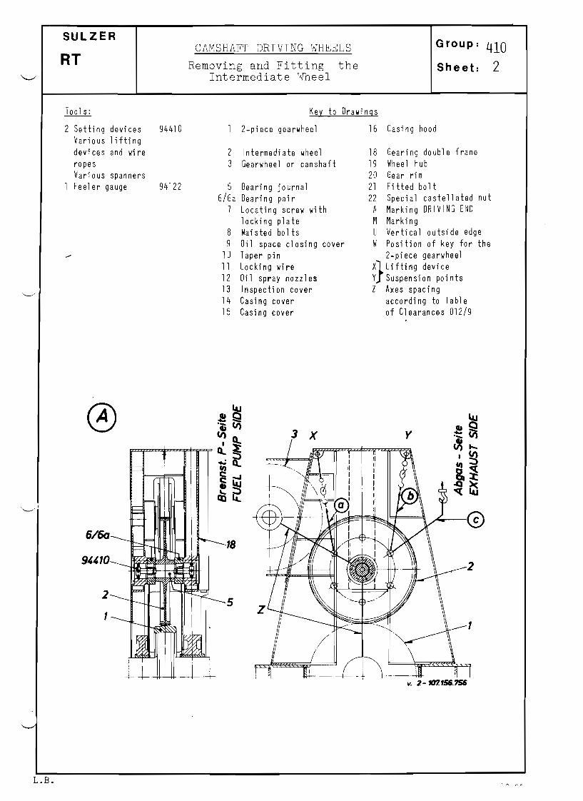
SULZER Group: 410CAMSHAFT DRIVING WHEELS
RT Removing and Fitting the Sheet: 2 Intermediate ~ h e e l
Too 1s: Key to Drawings
2 Setting devices 94410 2piece gearwheel 16 Casing hood Various lifting devices and wire 2 Intermediate wheel 18 Gearing double frame ropes 3 Gearwheel on camshaft 19 Wheel hub Various spanners 20 Gear rim Feeler gauge 94122 5 Bearing journal 21 Fitted bolt
6/6a Bearing pair 22 Special castellated nut 7 Locating screw with A Marking DRIVING END
locking plate M Marki ng 8 Waisted bolts U Vertical outside edge 9 Oil space cl osi ng cover W Position of key for the
10 Taper pin 2piece gearwheel 11 Locking wire X}Liftin g device 12 Oil spray nozzles y Sus~ension points 13 Inspection cover Z Axes spacing 14 Casing cover according to Table 15 Casing cover of Clearances 012/9
o 3 y
~I
6/60
2
1
v. 2-1t17.156.156
L.B.

410/2a RT
®
8
9
IIIIII
Huile Aceite ~
10gezeichnet fur RT 58 2DRAWN FOR RT 58 0-107. 197.091
7 t Del Oil
@
LoB. 2.8.1

410/2b RT
The following procedure has to be used if it is necessary to remove the intermediate wheel: (see also Figs. 'A', 'B' and leI).
Removal and fitting of the intermediate wheel (hereinafter referred to as wheel) is done from the exhaust side of the engine.
Removal
Put in the turning gear and bring the crank of No. cylinder to approximately the horizontal posi-tion.
Remove the fuses from the turning gear starter box so that it will not be possible to put the run-ning gear in motion whilst carrying out the following dismantling work.
Remove casing covers 14 and 15 (one each on fuel pump and exhaust side) as well as inspection cover 13.
Fit a lifting tackle each at points 'X' and 'Y' respectively in the gear column, attaching steel rope 'a' and Ib' (see Fig. 'All Pull the steel ropes through the holes foreseen in the gear wheel hub of the intermediate gear 2 and hook them into the lifting tackle (as for example shown in Fig. 'A'), pull the steel ropes slightly taut with the lifting tackle.
Now release the engine side bearing from its location from the crankchamber of cylinder No.1.
To do this, remove the locking wires 11 from all waisted bolts 8. Slacken off all the waisted bolts and remove them together with the oil space closing cover.
Pull off both taper dowels 10, which locate the bearing, from the gear double column 18 (use the pullers according to tools list sheet 9406).
Release the drive side bearing 6 in the same way, whereby here the waisted bolts and taper pins are accessible from the outside.
Lift the intermediate gear wheel including the bearing pair 6/6a with the lifting tackle, installed before, until it is raised by about hand width out of engagement with the teeth of the split gear wheel 1 on the crankshaft.
Take over the wheel with the lifting device hung at point 'Y' and pass it on with a further wire rope I c' (outsi de the engi ne) to the crane.
The bearings 6 and 6a can be pulled off the bearing journals 5 after removing the locating screws 7 and locking plates.
Neither the position of the crankshaft nor of the camshaft should be altered as long as the inter-mediate wheel is removed unless absolutely necessary.
Fitting
The fitting of the intermediate wheel 2 follows in the same way as removal but in reverse order. Pay particular attention to the following points:
Fit both bearings onto the journals after these have been liberally smeared with oil. In principle, both bearings are identical but must still be put back in the original position. This is because their positions were precisely fixed during initial assembly with taper pins (note numbering of the parts).
The intermediate wheel must be so installed that the marking "DRIVING END" can be seen when lookin from the driving end. The 'inscription is stamped on the edge of the gear rim, see ~on Fig. 'BI.
Where neither the crankshaft nor the camshaft have been turned during the time that the interme-diate wheel was removed, it can be replaced in any tooth position. Should, however, the position of either have been altered it will first be necessary to put it back into its correct installed position. The correct installed position is obtained when the following points have been achieved:
a) The crankshaft position must be so that the crank of cylinder No.1 is in T.D.C. (Cylinder No. 1 = fi rst cyl i nder by the fl ywheel )
b) The marks 'I~' on gearwheel 3 of the camshaft must 1i ne up wi th the verti cal outsi de edge 'u' of its bearing housing (hood 16 is removed).
I R

410/2c RT
Note: The position of the key for the 2piece gearwheel on the thrust bearing collar is dependant ant hen umb8 r afey 1i nd8 n 0 f the eng i nee aile ern ed• 1he an 91e ,0( I h g. I C' go es back the following from T.D.C.:
Anqle I cf. ,
No. of Cyl i nders RT58 RT58 RT75 RT84
4 40° 40 0
400
40 0
5,5,7 00
00
00
00
8 00
400
00
400
9,10,12 - 00
00
Bring the intermediate wheel (complete with bearings) back to its original place with the 1ifting devices and provisionally locate both bearings in the end frames 18. When doing so, only tighten the bolts so much that the bearing can still move a little as the taper pins are pushed in.
Carefully knock in the taper pins 10 into both bearings, using a copper drift; under no circum-stances may they lie proud of the sealing faces of the oil space closing cover 9.
Now remove the two provisionally fitted bolts from both sides again. Apply a sealing compound to the sealing faces between the oil space closing cover and the. gearing double frame. Put on both cover 9 with their waisted bolts and tighten the latter evenly by hand with a spanner.
Mark the wai sted bo 1ts wi th a dash at thi s posi tion and then ti ghten them further crosswi se and in a
stages through an angle of 45 •
As a precaution now check the tooth backlash between the gearwheels (see Table of Clearances 012/9)
Secure all waisted bolts in the 2nd group with wire.
Note: Should it be necessary to replace a bearing, the opposing bearing must also be replaced since new bearings are manufactured in pairs. When fitting them, the intermediate wheel must be pre-cisely set; the same applies to the replacement camshaft drive wheels. Use the setting device, tool No. 94410 when doing so.
See Table of Clearances 012/9 with regard to gear tooth backlash and axial spacing. The gear tooth contact pattern should also be checked and evaluated with engineers marking blue. Where it is necessary to repin the bearing, e.g. after fitting a ~ gearwheel set, etc., use the pin holes already predrilled in the frames. This work is best done by an experienced fitter who posseses the necessary instructions from the engine builder.
L. B. 11.84

410/2d RT
Remarks for the Repl acement of a spl it Oesi gn Gear Wheelan the Camshaft (Ill ustr. '0')
~ The removing and fitting is carried out as described above.
_ The replacement of a damaged split design gear wheelan the camshaft may only be done in exchange for
complete gear wheel i.e. the geared rim must be screw fastened to the hub and the bearing journal fitted. This is necessary as the final machining of the gear teeth has been carried out in this mountedcondition at the makers works and guarantees the required perfect true running of the complete gearwheel. Fot this reason a split design gear wheel may only be installed if the final machining of the
teeth had been carried out with assembled hub/toothed gear rim.
- After the final machining of the teeth the rim may not be separated from the hub.
- Should the damage be limited to the toothing (gear rim), then the hub may be re-used, provided a newrim, on which the teeth are not finishmachined is fitted to the hub, screw-fastened and dowelled towhich its teeth can be finished.
_ After fitting a spare gear wheel it is strictly recommended to place an order for another spare.
II
@
c<: 18 IILu
~ 8 8<::;: 9 89- 70Q:: I~c"-eli:t::ellII)
t I.Q6 6aell 5 7 7 Del IIIIII....
.b
~.c:
IiI Oil~ '"11
II Huile\
.,. ....,...........
Aceite
2119 10
22A
200-107.197.092
gezeichnet fiir RT58DRAWN FOR RT58
L.8.

SULZER Group:CAMSHAFT DRIVE WHEELS 410
RT Replacing the 2Piece Gearwheel Sheet: 3on the Crankshaft
Tools: Key to Drawings
2 Eye bolts M24 Upper gearwheel K Key way 1 Hydr. tightening 94412 half M Marking "DRIVING END"
device, 2 Lo we r gearwheel R Threaded holes for eye bolts comprising: half S Threaded holes for locating
1 Socket spanner 94412a 3 Waisted bolt screws 1 Spanner 94412b 3a Castellated nut T Blind holes for inserting the 1 Plate with pins 94412c 4 Locating screw tightening and loosening device 1 Hydraulic pump 94931 5 Locking plate W Drilling for fixing the tool 1 Jack 94938/a 6 Dowel pin during removal of thrust bearing 1 High~pressure hose 94435 7 Bedplate segmen ts 1 Feeler gauge 94122 1 Gauge or outside
mircometer Engineers marking blue
I-I o
I I
i I
t
~I i
I 1 ,~~ x
I I
~~ I ~~ s~ ~~" ~
l---------j. 0107.159.099
R
4 5

410/3a RT
Should it be necessary to replace the split gearwheel on the crankshaft coupling flange pair or the thrust bearing collar (hereafter referred to as gearwheel on crankshaft), the spare gearwheel has to be fitted. We strongly recommend that a new gearwheel be ordered immediately, giving exact details as to engine type and number. Thi s information is essential since the precei se diameters "Fl" and "F2" as well as total width "C" on the crankshaft are registered by the engine builder and the spare gearwheel will be manufactured to these dimensions. Under no circumstances may the "0 Fl" and 0 F2" be altered by filing or otherwise cutting back at the circumferential contact faces (see Fig. 1BI).
Work Procedure
Removing the Gearwheel
Engage the turning gear and bring the crank of the first cylinder approximately to top dead centre (T.D.C.).
Remove the intermediate wheel (see Sheet 410/2).
Remove the stopper bridge for the thrust bearing segments (see Sheet 120/2).
Turn the gearwheel on the crankshaft to a position such that the nuts 3a of the four waisted bolts 3 can be loosened from above (wheel separation horizontal).
Now position the tightening and loosening device 94412 with its pins inserted in the blind holes ~
IT' available for this purpose and together with the socket spanner 94412a on are of the castella-ted nuts.
Turn the spanner using hydro pump 94931 and jack 94938/a,pressing back the extended piston and bringing the spanner back to a better position as necessary.
Remove all the nuts 3a from the waisted bolts 3 and knock the bolts out. Attention! The locating screws 4 remain in place for the time being.
Screw two eye bolts into the threaded holes R and make the upper gearwheel half fast with a rope to a lifting device.
Remove the four locating Screws 4 from the upper gearwheel half, raise it and remove it from the crankcase.
Turn the crankshaft through 180 0
and remove the second gearwheel half in the same way.
2-107. 133.588
94438
94935
~ - 9 4 4 1 2 c
""---94412b
1
30
944120
94412c
94412b
T . R .
410/3b RT
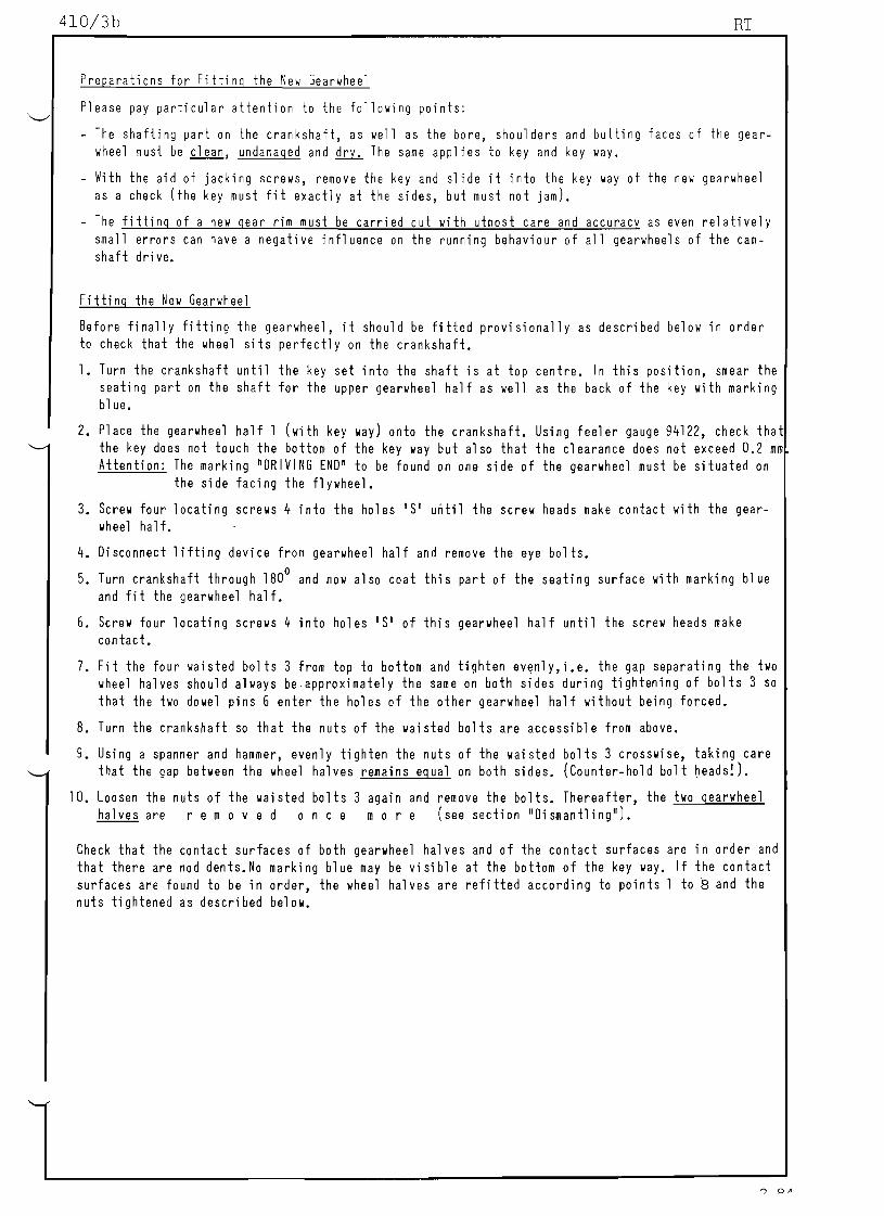
Preparations for Fitting the New Gearwheel
Please pay particular attention to the following points:
The shafting part on the crankshaft, as well as the bore, shoulders and butting faces of the gear-wheel must be clean, undamaged and ~ The same applies to key and key way.
With the aid of jacking screws, remove the key and slide it into the key way of the new gearwheel as a check (the key must fit exactly at the sides, but must not jam).
The fitting of a new gear rim must be carried out with utmost care and accuracy as even relatively small errors can have a negative influence on the running behaviour of all gearwheels of the cam-shaft dri ve.
Fitting the New Gearwheel
Before finally fitting the gearwheel, it should be fitted provisionally as described below in order to check that the wheel sits perfectlj on the crankshaft.
1. Turn the crankshaft until the key set into the shaft is at top centre. In this position, smear the seating part on the shaft for the upper gearwheel half as well as the back of the key with marking blue.
2. Place the gearwheel half 1 (with key way) onto the crankshaft. Using feeler g a ~ g e 94122, check tha the key does not touch the bottom of the key way but also that the clearance does not exceed 0.2 mm Attention: The marking nDRIVING ENDn to be found on one side of the gearwheel must be situated on
the side facing the flywheel.
3. Screw four locating screws 4 into the holes'S' until the screw heads make contact with the gear-wheel ha If.
4. Disconnect lifting device from gearwheel half and remove the eye bolts. o
5. Turn crankshaft through 180 and now also coat this part of the seating surface with marking blue and fi t the gearwheel half.
6. Screw four locating screws 4 into holes IS' of this gearwheel half until the screw heads make con tact.
7. Fit the four waisted bolts 3 from top to bottom and tighten evenlY,i.e. the gap separating the two wheel halves should always be,approximately the same on both sides during tightening of bolts 3 so that the two dowel pins 6 enter the holes of the other gearwheel half without being forced.
8. Turn the crankshaft so that the nuts of the waisted bolts are accessible from above.
9. Using a spanner and hammer, evenly tighten the nuts of the waisted bolts 3 crosswise, taking care that the gap between the wheel halves remains egual on both sides. (Counterhold bolt beads!).
10. Loosen the nuts of the waisted bolts 3 again and remove the bolts. Thereafter, the two gearwheel halves are rem 0 v e don cern 0 r e (see section IIDismantling ll l.
Check that the contact surfaces of both gearwheel halves and of the contact surfaces are in order and that there are nod dents.No marking blue may be visible at the bottom of the key way. If the contact surfaces are found to be in order, the wheel halves are refitted according to points 1 to 8 and the nuts tightened as described below.

.
E E
responding check lIIeasurelllents ge tolerance is aiAled at.)
'0F l ' and '0F 2 ' on the crankshaft. (During machining the aVerJ-
Working Seguence
After fitting the two gear wheel halves
the waisted bolts must be I€asured with (Note the bolt nUllbersl.
as
a V
per po
ernier
ints
call
1 to
iper
7,
or
the total le
a horseshoe
ngth ILl (see Fig.
lI1icrometer and rec
'AI)
orded
of
o Tighten the two bolts of one of the split faces with a spanner by hand (without the use of a hJmmer) until the gap on that split face is zero.
o Tighten the opposite two bolts in the salle lanner, whereby a gap jilin or j lax reAlains. (see I iy.'C ' ). '../
Should the gap be 1arger than j lax, the bores a f the gear wheel must be enl arged by an extremely sm.111 amount. Ihis can be done by careful scraping or grinding with elD~ry cloth arid J suitJlde piHe of \lood,
1.10/3c
Final tightening of waisted Bolts
©® Messbereich Messbereich
fur Fig. E fur Fig. E MEASURING RANGE MEASURING RANGE
FOR FIG. E FOR FIG. E .... t-- .... t-
t- -I-.
++ - ~ '+
I I
Messbereich
fur Fig. 0
MEASURING RANGE
FOR FIG. 0 ~
@
®
+) Thre ads and nut seating smeared with Molycote paste G.n
RT 38 RT 48
...(),07 0,09
...() , 11 ...() , 13
0,19 0,28 0,410,31
(II) 0, 6O:fO ,05 °,85:fO ,05
1800 2800
Engine
Tolerance AF (.. )
lin. (..)Cl earance j
.ax.
Bolt elongation AL
+Tightening torque Nm )
Attention! The two bores of the gear wheel '01' and '02' (see Fig,'BI) are smaller
Grar:
>< tl ·S
Grap:
C"')
Cl a-
II
Grap:
RT 58
...(),13
0,17
°,4!0,5
~,75:fO,05
3400
RT
(leu nal'0; tittea, Lolts ur:-
tensioned (only tightened by
hand IIi th spanner)
Between the spl it faces in the
measuring range for fig. C"')
, 0I (a cc. Fig.' BI) Bo 1t s Cl,
fully tighte ed '; >( tl
E
In the measuring range for fig. , [ I (a cc. Fig.' BI)
tightened)
RT 62
RT 68
...(),15
...(),19
0,47 0,60
1,0:fO ,05
5100
RT 76
...(),18
...(),22
0,57 0,69
1,JS:fO,OS
6300
by L::. F than the cor-
(801 t stu11Y
C) Cl
I'
RT 84
...(),20
...(),24
0,63 0,75
1,05:fO ,05
8500
9.85

410/3d RT
When the described initial position according to Fig. Ie' is reached in the measuring range for Fig. '0' (Gap = 0 and j rain. ~j ~ j max.)loosen the two waisted bolts of that gear wheel separating face si-
de havtng 0 _ clearance and tghten instead the waisted bolts of the gear wheel separating face side
having j clearance correspondingly more, so that finally in the measuring range for Fig. 10 1
(see Fig.
"' 'BI) i.e. in the teeth region the clearance on both sides is equal.
_ Tighten the waisted bolts crosswise with tightening device 94412 equally till their total length (see
Fig. 'A') has increased by at least.o. L.
_ In this condition between the teeth (in the measuring range for Fig. 10' in Fig. 'B' should the clea-
rance between the two separating faces by maximum 0.03 mm (Fig. '0').
_ In the measuring range for Fig. IE', Fig. 'B' i.e. on the outer edges between the shoulders the clea-
rance:should be practically zero. (Fig. IE').
1985
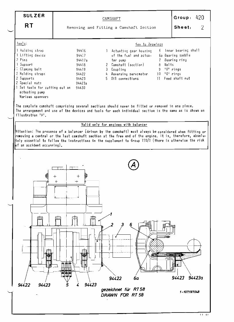
SULZER Group: 420CAMSHAFT
RT Removing and Fitting a Camshaft Section Sheet: 2
Too 1s: Key to Drawings
1 Holding strap 94416 Actuating gear housing 6 Inner beari ng shell 1 Lifting device 94417 of the fuel and actua- 6a Bearing saddle 2 Pi ns 94417 a tor pump 7 Bearing ring 1 Support 94418 2 Camshaft (section) B Bolts 1 Clampng bolt 94419 3 Coupling 9 '0' rings 2 Holding straps 94422 4 Reversing servomotor 10 '0' rings 2 Supports 94423 5 Oil connecti ons 11 Feed shaft nut 2 Special nuts 94423a 1 Set tools for cutting out an 94430
actuati ng pump Various spanners
The complete camshaft comprlslng several sections should never be fitted or removed in one piece. The arrangement and use of the devices and tools for each individual section is the same as is shown on illustration 'A'.
Valid only for engines with balancer
Attention: The presence of a balancer (driven by the camshaft) must always be considered when fitting or removing a central or the last camshaft section at the free end of the engine. It is, therefore, absolu-tely essential to follow the instructions in the supplement to Group 770/1 (there is otherwise the risk f an accident occurring).
1-107.197.0t.8gezeichnet fur RT 58
DRAWN FOR RT 58
, 1 0 I

420/20
Removal of a Camshaft Section
_ Remove the front and side casings from the fuel pump actuating gear housing.
_ furn the engine with the turning gear and simultaneously raise the rollers together with their guides of III the fuel and actuator pumps from their cams. Refer to Group 55126 of the Service instructions
Manual for thi s. Make ready the cutout devices for cutting out the actuator pumps (one tool 94430 for each actuator
pump) •
Slacken off and remove the tie rods with distance tubes which Jie vertically in front of the camshaft
bearings to reinforce the fuel pump actuating gear housing.
_ Release the shaft couplings which connect the camshaft section to be removed from its neighbouring units according to the instructions given on sheet 421/1g. The markings on the shafts and couplings make it possible to precisely reposition a ~ l the components during later reassembly.
_ Now slide the released couplings onto the camshaft sections which will not be removed
_ Unscrew bolts 8 and pull down the oil connections 5 until there is no longer any connection between them and the bearing ring 7 of the reversing servomotor 4 (see Figs. 'A' and 'B').
_ As shown in Fig. 'A' attach a holding strap 94422 each on the front face of the drive housing; fhese prevent the camshaft accidentally slipping out of its bearings, while the bearing covers are being loo-
sened and removed.
_ Slacken off both bearing caps and remove them. Replace them with the supports 94423 with the related special nuts 94423a on the now accessible bearing saddle 6a.
_ Remove both the holding straps 94422 and rollout the camshaft section onto the supports 94423. Lift
the unit from there with the aid of a crane. When removal will be carried out using the procedure whereby the cams will be pulled off the camshaft section, this can be prepared with the tool set according to Fig. 'e' and carried out there and then. Where the fuel cams, e.g. to the right of the reversing servomotor will be pulled off the shaft then the holding clamp 94416 has to be mounted on the left of the drive housing. Fit support 94418 at the
same time.
Lay the lifting device 94417 on the supp~rt 94418 and position this at the same time with the two pins
94417a which have to be inserted up in the drive housing.
_ Clamp the bearing ring 7 of the reversing servomotor 4 with clamping bolt 94419 (see detail Section
I I-Ill.
_ Use a screwdriver on the feed shaft nut 11 and thereby raise the camshaft
® section enough to unload a support 94423 which can then be removed.
For further procedure, particularly for pulling off and on of a fuel and actuating cam, seee information in
Group 421.
10
1
5
7
8
11 .84~ . B.

420/2b RT
@ c§l51~ _..... -1
I
IJ ~=. I
=~ ~ -t·
I I
1
Gezeichnet fur Nocken demontage rechts
DRAWN FOR DISMOUNTING THE CAMS ON THE RIGHT HAND SIDE OF THE REVER SING SERVO MOTOR
9 ~ 4 1 9 (RT 62)
111-111
1
9~~23
0-107. 217. 136
1985

420/2.c RT
Fitting a Camshaft Section
Fitting follows in the reverse order or removal. Please not the follolling points:
The numbering of the individual parts IIhich belong together must concur.
The contact surfaces of the supports onto IIhich the camshaft section to be fitted lIill be placed must be clean. The same applies to the camshaft bearing journal s and bearings.
Shortly before rolling the shaft into its bearings lubricate the bearing surfaces liberally lIith clean oil.
When fitting the camshaft bearing shells particular care has to be taken to ensure that the pin in the bearing cap engages properly in the hole on the back of the outer bearing sh~ll half.
Furthermore, the inner bearing shell must be so placed in the axial direction that both its pins, IIhich are in the butting faces, can engage properly in the relevant holes in the outer bearing shell IIhen fitting the bearing cap. The best thing is to put the bearing together provisionally before fitting the shaft, so long as the inner bearing shells can still be slid sidellays.
Attention!
The clamping bolt 94419 must be removed from the reversing servomotor and the three oil connec- tions 5 pulled up and led into the bearing ring 7 before the couplings 3 are pressed into the shaft connections.
When sliding on and positioning the couplings, check that the locating marks on the shaft ends to be connected concur. With regard to pressing on the shaft coupling lIith hydraulic fitting tools, see Sheet 421/2 and 421/3.
Tightening the Studs of the Camshaft Bearings
Once the camshaft is in its bearings and their bearing caps are fitted, tighten down both the nuts evenly lIith a spanner by hand until meta1tometal contact is obtained.
NOli tighten the nuts equally in little steps alternately, using the ring spanner and hammer.
Where a final check shows that the vertical bearing clearance of the camshaft bearings (see Table of Clearances 012/10) is in order, the nuts can be secured with the locking plates.
I 0 " 0 I

SULZER
RT
Steuer~elle/Camshaft
Demontage u. Montage der hydro Pressverbande
Dismantling and Assembling of Hydraulically Fitted Components
Gruppe: 421
Blatt: l:)
Steuerwel1enkupplung, Hubgebernocken und Brennstoff-
nocken werden mittels Hydraul ikwerkzeug montiert,
ausgerichtet (eingestellt) und demontiert.
(Details siehe 421/1 + 3)
Coupling for camshaft, actuator cam and fuel cam are
fixed with the oil injection method. They are mounted,
adjusted and taken off with separate hydraulic tool.
(For details see 421/1 + 3)
DemontagejDlsmantling
Turn engine and lift rollers.
Hydraulic tool to be fixed to couplings.
Coupl ings to be s1 id in axial direction.
Bearing covers to be taken off and connections for
regulating oil to be lowered.
Motor schalten und Rol len abheben.
Hydr. Werkzeug auf Kupplung montieren.
Kupplung lasen und diese axial wegschieben.
Lagerdeckel entfernen und Umsteueralanschlusse ab-senken.
Hydr. Werkzeug
HYDR. TOOL
Steuerwelle aus dem Gehause rollen.
Hydr. Werkzeug auf Hubgebernocken montieren.
Camshaft section to be rolled out of housing
Hydraulic tool to be fixed to actuator cam.
Hydr. Werkzeug
HYDR. TOOL
Hubgebernocken entfernen und hydro Werkzeug auf
~rennstoffnocken montieren
Hydr. Werkzeug
HYDR. TOOL
Actuator cam to be taken off.
Hydraulic tool to be fixed to fuel cam.
BrennstotfnocKen entfernen. Fue1 cam to be taken off.
Montage: Gleich wie Demontage, in umgekehrter Reihenfolge Assembling: Same as dismantling but in reverse order
L.B. 1984

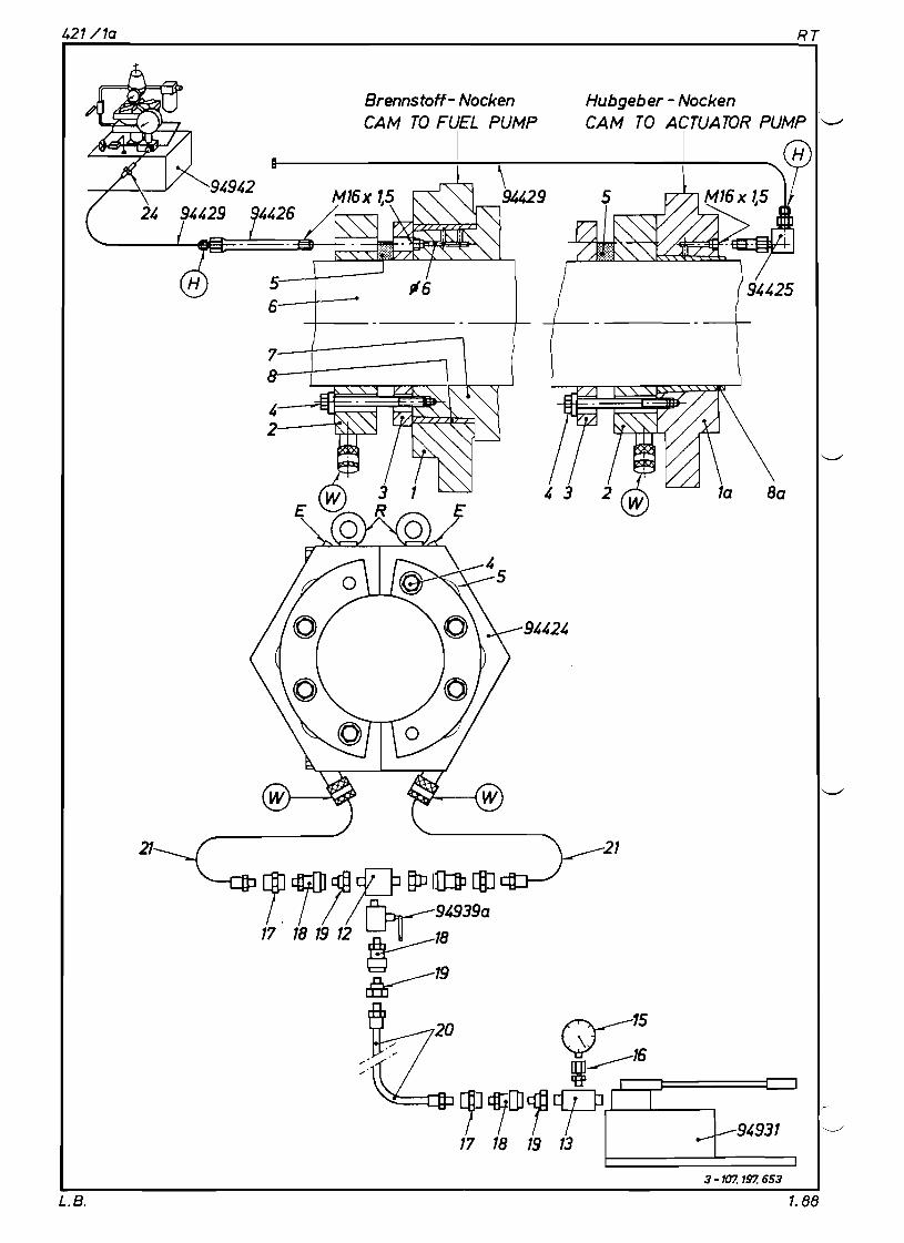
SULZER Group: 421
CAMSHAFTRT
Sheet: 1Removing the Fuel and Actuator Cams '-'"
Tools: Key to Drawings
1 Jacking tool 94424 1 Fuel cam E Vents 1 Connecting piece 94425 1a Actuator cam Q) Connection from oil pump 1 Connection 94426 2 Piston carrier 94942 1 Connection 94427 section G) Connection from oil pump 1 Centering disc 94428 3 Ring piece (2part) 94931 1 Hose pipe 94429 4 Bolts @ Connection from oil pump
(1500 bar) 5 Pi ston (total 6 off) 94931 a 1 Suspension strap 94431 6 Camshaft R Eye bolts 1 Oi 1 pump 94931 7 Sl eeve 1 Oi 1 pump SKF 94931a 8 Liner 1 Oil pump 94942 8a Bush 1 High pressure 94935 9 Flange coupling
ho se 10 Guide plate 2 High pressure 94935a
hoses '.../ See Group 940/0a for tool detail s
Note: Three high pressure oil pumps of various designs are required when carrying out the work in Group 421, Sheets lli described below. Fill up both pumps (Tool No. 94942 and 94931) before use with an oil of viscosity grade SAE 40.
The nonreturn valve 94939a inserted between oil pump and jacking tool 94424 serves a special purpo-se. When pumping, the nonreturn valve must always be closed. In this valve position oil can reach the jacks but cannot escape back. The lowering of existing pressure in the jacking tool can be very finely regulated by careful opening of the nonreturn valve.
Removing the Cams
Work Procedure:
~ Place the camshaft section in a clearly accessible and clean area.
Slide tool 94424 over the shaft against the cam.
Screw in and tighten connecting pieces 94426 and 94425 to connection 'HI in the threaded hole M16 x 1.5 (with oil connection drilling 0 6 at the bottoml.
Screw in all the bolts 4 for mounting the tool, on the sleeve 7 and on the actuator cam itself, by hand but do not tighten them.
Connect up the oil pump 94931 with high pressure hoses and appertaining fittings to connections IWI and oil pump 94942 to connection 'H' as shown on the illustration.
Open both vent scre~s 'EI on tool 94424 and operate the high pressure pump until the oil escapes bubblefree. Shut the two vent screws.
Extend the piston and evenly tighten all bolts 4.
Oil may only be applied to connection 'HI after the oil pressure in the tool (connection 'WI) has been set at 30 to 50 bar.
Pressure may only be built up at connection 'H' when the tool has been correctly fitted and is under pressure. Accident risk!
When oil appears around the full circumference of the jack seat, oil from the seam, the pressure in the tool can be slowly reduced, whereby the cam is loosened.
ATtach suspension strap to fuel injection or actuating cam respectively as shown in illustration on sheet 421/1i. Lift cams with the aid of a hoist from the sleeve 7 or the camshaft 6 respective-ly together with the bushes 8.
1. 89L. B.
421/10 RT
Hubgeb er - Nocken
CAM TO ACTUA TOR PUMP '-"
5
6
7
Brennstoff- Nocken
CAM TO FUEL PUMP
I H
3 -107. 197. 653
L.B. 1.88

SULZER Group:CAMSHAFT 421
RT Pressing on the Fuel Pump Cam Sheet: IB ~
Tools: Key to Drawi ngs
See Sheet See Sheet 1
Connecti on E according to Sheet la
94424
1
,/ 4 107. 197. 367
Clean all seating surfaces before fitting.
Slide the cam with liner onto the sleeve of the reversing servomotor. Ensure that the cam and liner are flush with each other. Slide the jacking tool along to the cam, screw connecting piece 94426 into connection 'H' (note drilling 0 6), then tighten all mounting bolts 4 evenly by hand. Connect pump 94931 to connections 'w' and pump 94942 to connection 'HI. --
Open both vent screws' E' on tool 94424 and operate the hi gh pressure pump until the oil escapes bubblefree. Shut the two vent screws.
Apply pressure to the taper with connection 'H' until oil escapes on both sides between reversing servomotor sleeve 7 and liner 8 around the full circumference.
By slowly increasing the oil pressure in the tool the cam will move slowly axially. The pressure at connection 'H' will rise continuously to about 550 bar. Oil must flow from both sides of the cam during the whole tightening procedure.
When the end position is reached, i.e. the cam and liner are at the limit stop, first release the oil pressure in connection 'HI and then, after about 30 seconds, the pressure in the tool.
Dismantle tool.
Connection according to Sheet 1a
L.B. 1.89

SULZER Group: 421
CAMSHAFTRT
Sheet: IePressing on the Actuator Cam
Tools: Key to Drawings See Sheet 1
See Sheet
Connection according
L @)
Connecting according
4 107. 197. 368
to Sheet 1a
to Sheet 1a
Clean all seating surfaces before fitting.
Slide the cam and liner onto camshaft and position (note recess). Bolt on jacking tool whereby all the bolts 4 must be tightened evenly by hand. Connect pump 94931 to connections 'w' and pump 94942 to connection 'H'.
Open both vent screws 'E' on tool 94424 and operate the high pressure pump until the oil escapes bubblefree. Shut the two vent'screws.
Apply pressure to the taper with connection 'HI until oil escapes on both sides around the full circumference.
By slowly increasing the oil pressure in the tool the cam will move slowly axially. The pressure at connection 'HI will rise continuously to about 800 bar. Oil must flow from both sides of the cam during the whole tightening procedure.
When the end position is reached, i.e. cam is flush with the liner, first release the oil pressure in connection 'HI and then, after about 30 seconds, the pressure in the tool.
Dismantle tool.
Attach suspension strap to fuel injection or actuating cam respectively as shown in illustration on sheet 421/1i. Lift cams with the aid of a hoist from the sleeve 7 or the camshaft 6 respectively together with the bushes 8.
Remark: When replacing an actuator cam la, its bush 8a must be replaced at the same time. Both
parts form one unit and must not be interchanged. For spares orders bush and cam are always supplied together.
L.B. 1.89
SULZER Group: 421CAMSHAFT
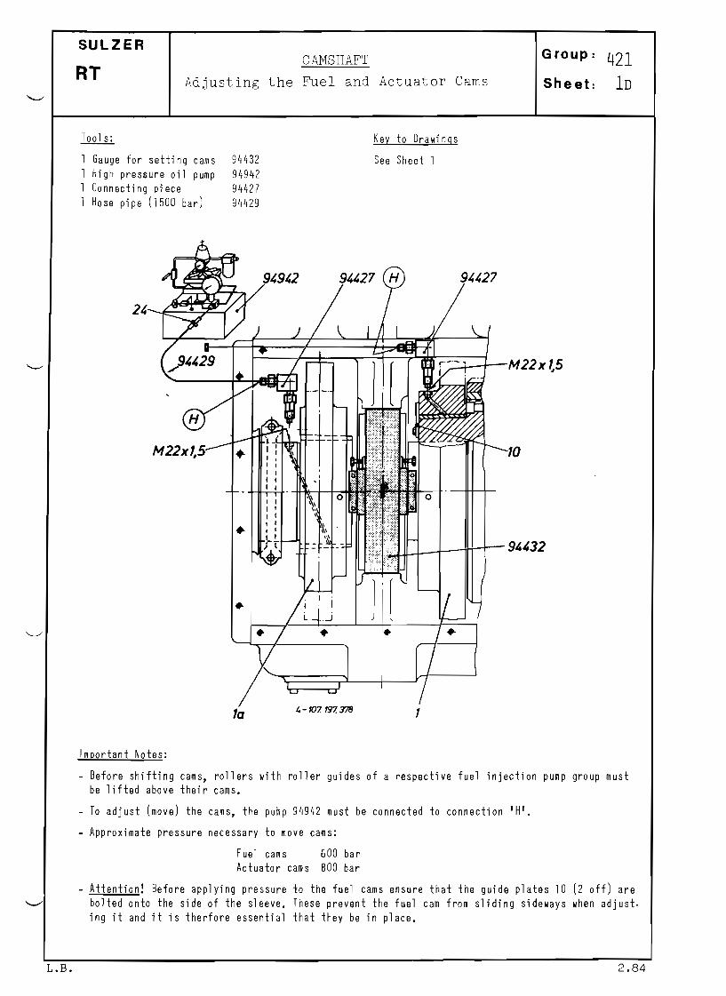
RT Adjusting the Fuel and Actuator Cams Sheet: 1D
Tools: Key to Drawings
Gauge for setting cams 94432 See Sheet 1 High pressure oil pump 94942 Connecting piece 94427 Hose pipe (1500 bar) 94429
. ~--+-M22 X 7.5
M22xl,5 10• 0
.. 9"32
..
1, - 107. 197. 378la
I I
I I I
I
rr:
Important Notes:
Before shifting cams, rollers with roller guides of a respective fuel injection pump group must be lifted above their cams.
To adjust (move) the cams, the pump 94942 must be connected to connection 'HI.
Approximate pressure necessary to move cams:
Fuel cams 600 bar Actuator cams 800 bar
Attention! Before applying pressure 10 the fuel cams ensure that the guide plates 10 (2 off) are bolted onto the side of the sleeve. These prevent the fuel cam from sliding sideways when adjust. ing it and it is therfore essential that they be in place.
L.B. 2.84
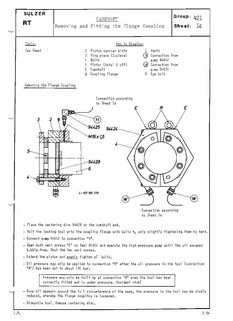
SULZER Group: 421CAMSHAFT
RT Removing and Fitting the Flange CouDling Sheet: IE
Too 1s: Key to Drawings
See Sheet 2 3 4 5
6
9
Piston carrier plate Ring piece (2piece) Bolts Pi ston (total 6 off) Camshaft Coupling flange
E
Q)
G)
R
Vents Connecti on pump 94942 Connection pump 94931 Eye bo It
from
from
Removing the Flange Coupling
Connection according to Sheet 1a
E R E
4 707. 797. 379
Connection according
to Sheet 1a
Place the centering disc 94428 on the camshaft end.
Bolt the jacking tool onto the coupling flange with bolts 4, only slightly tightening them by hand.
Connect pump 94942 to connection 'H'.
Open both vent screws IE' on tool 94424 and operate the high pressure pump until the oil escapes bubblefree. Shut the two vent screws.
Extend the piston and evenly tighten all bolts.
Oil pressure may onl y be applied to connection 'HI after the oil pressure in the tool (connection 'W') has been set to about 100 bar.
Pressure may only be built up at connection 'H' when the tool has been correctly fitted and is under pressure. Accident risk!
Once oil appears around the full circumference of the reduced, whereby the flange coupling is loosened.
seam, the pressure in the tool can be slowly
Dismantle tool. Remove centering disc.
L. B. 2.84-

421/1f RT
Fitting the Flange Coupling
Connection according
to Sheet la
3 2
---~ E R
\
\ \
94425 .~~
"'-MI6xl,5
4 107. 197. 380
Connection according to Sheet 1a
Clean all seating surfaces before fitting.
Position the flange with liner on the camshaft. Note marks on liner, flange and camshaft.
Bolt on the jacking tool, whereby all bolts must be tightened evenly by hand. Connect pump 94931 to connecti ons I WI and pump,94942 to connecti on I HI.
Open both vent screws 'E' on tool 94424 and operate the high pressure pump until the oil escapes bubblefree. Shut the two vent screws.
Applly pressure to the taper with connection 'HI until oil escapes on both sides around the full ci rcumference.
By slowly increasing the oil pressure in the tool, the flange will move slowly axially. The pres-sure at connection 'HI will ri se continuously to about 1000 bar. Oil must flow from both sides of the flange during the whole tightening procedure.
When the end position is reached, i.e. flange flush with liner, first release the oil pressure in connection 'HI and then, after about 30 seconds, the pressure in the tool.
Dismantle tool.
L. B. 2.84

SULZER CAMSHAFr Group: 421
Removing and Fitting theRT Sheet: 1GCamshaft Coupling
Removing the Camshaft Coupling
E R E
9~931a
/
5
Connection according to Sheet 1a
Bolt on the tool 1i ghtl y with bolts 4. Connect pump 94931 to connections' W' and pump 94931 a to connection'S'.
- Open both vent screws IE' on tool 94424 and operate the high pressure pump until the oil escapes bubble-free. Shut the two vent screws.
- Extend piston and evenly tighten all bolts.
- Set the pressure in the tool to 300 bar and then apply pressure at connection'S'.
Pressure may onl y be bui lt up at connecti on IS' when the tool has been correctly fitted and is under pressure. Accident risk!
When oil appears around the full circumference of the seam, the pressure in the tool can be slowly reduced, whereby the outer sleeve will slide slowly off the liner.
- Dismantle tool.
L. B. 2.84

421/1h RT
Fitting the Camshaft Coupling
949310 /I i
'" -107. 197. 383
Connection according to Sheet la
Clean all seating surfaces before fitting.
After mounting the shafts the axial gap between them may not exceed 1 mm. The two shaft ends must be exactly aligned. Check: Roller of fuel cams must be aligned.
Push coupling over the camshaft and place in correct position, dimension A.
The marks on the shaft ends must correspond. Position the coupling as illustrated. Bolt on the jacking tool, whereby all bolts must be tightened ~ by hand. Connect pump 94931 to connections 'II" and pump 94931a to connection'S'.
Open both v~nt screws 'E' on tool 94424 and operate the high pressure pump until the oil escapes bubblefrQe. Shut the two vent screws.
Apply pressure to the taper with connection'S' until oil escapes on both sides around the full cir-cumference.
By slowly increasing the oil pressure in the jacking tool, the outer sleeve will slowly slide onto the inner sleeve. Oil must flow from both sides of the coupling during the whole tightening proce-dure.
When the end position is reached, outer and inner sleeves are flush, first release the oil pressure in connection IS' and then, after about 30 seconds, the pressure in the tool.
Dismantle tool.
L. B. 2.87

421/1; RT
Aufhangelasche fur Brennstoff-und Hubgebernocken -Transport
LIFTING LUG FOR FUEL AND EXHAUST CAM TRANSPORT
94431
Brennstoff - Nocken
FUEL CAM
geze;chnet fur RT 58 DRAWN FOR RT 58
4-107. 240.075
L. B. 1986

SULZER
RT CAMSHAFT
Removing and Fitting of
SKF Shaft Coupling
Group: 421
Sheet: 3
Tools:
Hydr. hand pump Hand oi 1 pump SKF Pressure gauge High pressure hose
o 94932
94931
94931 a
94932
94935
Anschluss
CONNECTION
Anschluss
CONNECTION
Key to III ustrati ons
1 Cam sha ft 8 Nut 2 Inner sleeve 9 Seal ring 3 Outer sleeve 10 Threaded pin 4 Pressure oil pipe P Fi tti ng cl earance 5 Valve screw R Ring space 6 Refl ux val ve "HPC" HIGH PRESSURE CONNECTION
7 Name plate "LPC" LOW PRESSURE CONNECTION
Achtung ! ATTENTION! MAX. OIL PRESSURE 25MPa (250barJ
LPC-----J
HPC ----.J ,Entliiftungsbohrung
VENT HOLE
L. B. 1985

421/3a RT
Removi nq an SKF Shaft Coupl i nq
Working Sequence
Connect pressure oil apparatur, consisting of hand pumps 94931 and 94931a and pressure oil pipe 4, to the coupling as shown on Fig. IA'. Bring oil pressure in the ring space at LPC with hand pump 94921 to about 200 bar (20 MPa) and keep this pressure constant. The pressure in this ring space may under nJW circumstance exceed 250 bar (25 MPa); the caption on the name plate 7 is meant to draw attention to t his!
With hand oil pump (SKF 94931a press oil at "HPC" into the fitting clearance 'pI till it issues along the whole circumference between the sleeves. On bigger cJup1ings thi~ ~ay take ~ ~ v e r a l minutes.
If the coupling is very cold and the oil from this pump only manageable with difficulty the heat the coupling up a little. Recommended temperature 20 30 0 C.
® 1
R
Open reflux valve 6 on the pump 94931 connected to ring space 'RI till the outer sleeve 3 slowly slides off the inner sleeve 2. Should the outer sleeve not get loose, press some more oil into the gap clearance 'pi between the sleeves with pump 94931a. Slight tapping on the inner sleeve can also assist the loo
sening of the outer sleeve.
- Clean the shafts on both ends of the coupling, shut connection bore "LPC" and the vent hole, whereby the shifting force is only transmitted by the oil enclosed in the ring space, thereby preventing a jamm
ing of the seal ring 9. Now push the coupling fully onto one shaft end.
I P

421 3b RT
Fitting an SKF Shaft Coupling
Working Sequence
Clean coupling seats and bores of the inner sleeve. Smear coupling seats slightly with thin oil.
Push shaft coupling onto camshaft.
When joining the two shaft pieces the axial gap between them must be maximum 1 mmj the shaft ends therefore have to be very accurately aligned.
- The marks on the shaft ends must correspond (Fig. '0'). Place shaft coupling according to Fig. 'cr.
Rl/l,"
,R3/l,"
ill
RT 58 RT68 RT76 RT81, RT62
161, 177 14013{5 149A
Connect the pressure oil pipe 4 of oil hand pump 94931 to "LPC" for the ring space of the outer sleeve
and open the vent hole nearby. Screw hand oil pump 94931a firmly into the connection bore G 3/4" of the
outer sleeve and press oil (SAE 30) into the clearance gap 'pi until it flows out at the thicker end of
the inner sleeve. With pump 94931 feed oil into the ring space until it flows from the vent hal e without bubbling. Shut vent hole and by continual oil feeding drive the outer sleeve onto the inner sleeve, taking care that the pressure indicated on the pressure gauge never exceeds 250 bar (25'MPa). Continue pumping oil into the fitting clearance to maintain the oil film. The press fit is completed when the inner sleeve protrudes by 10 mm. (Fig. '0').
® Marken MARKS
Atteorl:i on!
- Open the valve screw 5 of the oil pump 94931a to allow the oil from the fitting clearance 'pi to return
to the oil container. Loosen the pressure oil pipe from "LPC" and remove with oil pump 94931. Shut the connection bore -LPC" with the corresponding threaded plug. The remaining oil is not drained from the
ring space.
L.B. ? P7

RT421/3c
After the first fitting, the nut 8 must be retightened; Loosen locking set screw and threaded pin 10 (Fig. lEI) to unlock the nut, tighten the nut 8, then lock the nut again by hard tightening threaded pin
10, lock threaded pin with set screw.
® 10
8 9
1n. R~ I. B.

SULZER CAMSHAFT Group: 421
Removing and Fitting the Gear1,TheelRT Sheet: 4to the Camshaft
Too 1s: Key to Drawings
2 Holding straps 94420 1 Bearing housing 7 Platform beam 2 Supports 94421 2 Camshaft 8 Gearwheel for verti ca 1 dri ve
Var. spanners 3 Coupling 9 Distance ring 4 Gear rim S Bolt s 4a Gearwheel hub * Threaded holes for taking 5 Adjusting screw the bolts lSI when tool is 6 Inner bearing shell not being used 6a Beari ng saddl e
Valid only for engines with balancer
Attention: The presence of a balancer (driven by the camshaft) must always be considered when fitting or removing the gearwheel on the camshaft. It is, therefore, absolutely es
sential to follow the instructions in the supplement to Group 770/1 (there if otherwise the risk of an accident occurring).
o gezeichnef fur RT58 DRAWN FOR RT 58
94421
1- 107. 197, 047•
Removal
Should it be necessary to remove the gearwheel on the camshaft, proceed as follows:
- Bring the crankshaft of the first cylinder to T.D.C. (first cylinder at flywheel is cyl. No.1). Remove the casing hood above the gearwheel to be removed from bearing housing 1; the locating marks 1M' on the gear rim must line up with the outer edge lUI of the bearing housing (see Group
410/2).
- For safety reasons take precautions to ensure that, while the work is being done, the turning gear remains en a ed but cannot be turned.
L.B. 2.84

421/4a
Remove the 2piece closing cover on the left and right side of tre bearing nousing as well as the hood (front).
Release the shaft coupling 3 according to instructions on Sheet 42i/ 19
Slide the now loosened coupling onto the neighbouring camshaft section.
The transmitter for the overspeed safety cutout must also the bearing housing.
Fit two holding straps 94420, one off per bearing saddle, vent the gearwheel with its bearing journals from sliding
be removed from the drive side wall of
sideways as shown on Fig. 'A'. These pre-out of its bearing by itself when the
bearing caps are being slackened off and
Slacken off and remove both the bearing si bl e bearing saddl e 6a.
Adjust the supports with the aid of the the platform beams 7.
removed.
caps and then bolt the supports 94421 onto the now acces-
adjusting screws 5 so that they are solidly supported on
After removing both the holding straps 94420, the gearwheel, complete with camshaft 2, can be rolled out onto the supports 94421 and from there be lifted away by crane.
If the gear rim 4 with hub must be taken down for further dismantling of the camshaft, it is essen-tial to check before any dismantling work is started if the gearwheel is marked together with its camshaft.
® Markierung/DRIVING END
8
2
9
gezeichnet fur RT 58 DRAWN FOR RT58
9
3-107.197.339
L.B.

421 4b RT
Fitting
The gearwheel is fi tted to the camshaft in the reverse order or removal. Pl ease note the foll owi ng points when doing so:
Note: During reassembly and later fitting of the gearwheel on the camshaft, ensure that gear rim 1 ap-pears with its marking ~DRIVING END~ when looking at it from that end. The locating marks 'M' on the gear rim for the correct 'camshaft drive wheel position' are stamped on the same side (see Fig. 'B'l.
The identification numbers of the individual parts must correspond with each other.
All parts must be cl ean, undamaged, and lightl y oil ed before assembl y.
After the gearwheel on the camshaft has been rolled back into its bearings and both the holding straps have been fitted to stop it from rolling out by itself, a check has to be make if: 1) The locating marks 'M' on the gear rim correspond with the vertical outside edge lUI of the housing. 2) The gearwheel 8 for the vertical drive (bolted onto gearwheel hub 4a) is correctly engaged with the
opposi ng gearwheel.
Evenly tighten the bolts of the camshaft bearings using a ring spanner and hammer. When a final check shows that the vertical bearing clearance of the camshaft bearing (see Table of Clearances 012/10) is in order, the bolts can be secured with the locking pl ates.
When hydraulically tightening the shaft coupling 3, check that the marks on the shafts to be connected concur.
With the oil pump running, check the oil supply to the bearings before finally fitting the hood.
Remarks for the Replacement of a split Design Gear Wheel on the Camshaft (Illustr. 'BI)
The removing and fitting is carried out as described above.
The replacement of a damaged split design gear wheel on the camshaft may only be done in exchange for a complete gear wheel i.e. the geared rim must be screw fastened to the hub and the bearing journal fitted. This is necessary as the final machining of the gear teeth has been carried out in this moun-ted condition in the makers works and guarantees the required perfect true running of the complete gear wheel. For this reason a split design gear wheel may only be installed if the final machining of the teeth had been carried out with assembled hub/toothed gear rim.
After the final machining of the teeth the rim may not be separated from the hub.
Should the damage be limited to the toothing (gear rim), then the hub may be reusedj provided a new rim on which the teeth are not finishmachined is fitted to the hub, screwfastened and dowelled to which its teeth can be finished.
The gear wheels for the auxiliary drives can be transferred to the replaced gear wheel.
After fitting a spare gear wheel it is strictly recommended to place an order for another spare.
L. B. 10.86

SULZER Group: 430
RT Removing anj Fitting the Pilot V a l v ~ s Sheet: 1
Tools: Key to Drawings
1 Extraction device 94451 Upper shaft of the 10 Large holding pin 17 Support
1 Feeler gauge 94122 vertical drive lOa Small holding pin 18 Bo It 2 Pilot valve sleeve 11 Cover 19 Locating pin
3 Pilot valve 11a Screws 20 I~ ut
4 Housing 12,12a Beari ng flange 21 Threaded studs
5 Starting timing cam 22 Extension piecesbush
Closing ~ ~~}Beari ng 23 screws6 cover Jacking
7 Pin for roller 14 Taper pin 24 Oval fl ange
8 Ro 11 er 15 Dowel pin 25 Nut 9 Tension spring 16 Taper pin S Clearance
SL Bearing clearance
We recommend that during each 4year survey a random check be made by removing two pilot valves 3 with sleeves 2 from housing 4 of the starting air control air distributor and to clean and examine them. (For reasons of safety, close the shutoff valve of the starting air receiver when carrying out this wo rk 1. The condition of the pilot valves removed will determine whether the remainder may be left in position or whether they all have to be removed. Should the pilot valves be very dirty, this means that the air supplied is not being cleaned sufficiently (poor condition air filters, etc. on the compressor).
When pushed forward in their sleeves 2, the pilot valves 3 should move easily and be pulled back again by their spring 9. Roller 8 should turn easily on pin 7. Spring 9 must pull pilot valve 3 back until the latter rests against the large holding pin 10.
8 5
1~
19,
110
11
3-------J 100 ---J
2-------J '-107. 071. 730
2.84

430/1a RT
Application fa extracting device 94451 for removal of pilot valve sleeves
b
® 24
22
c 23
20
25
a
1-107 073. 797 .~.
* When fitting the sleeve, place nut 20 under flange 24 if the sleeve cannot be pushed in by hand.
L.B. 2.84

430/1b RT
Removal
Loosen screws 11 a and remove cover 11.
Bolt on device 94451 according to Fig. 'a' of I 11 us. 'B' and, by tightening nut 20, pull out sleeve 2 with the complete pilot valve 3 until it makes contact with the oval flange 24. It may then be possible to remove sleeve 2 by hand, using jacking screw 23. If not, screw the two extension pieces 22 onto the threaded studs 21, refit flange 24 and pull the sleeve out completely by turning nut 20 (Illus. 'B', Fig. 'c').
For further dismantling, push the large holding pin 10 out sideways, thus allowing the pilot valve with spring 9, roller 8 and pin 7 to be removed.
The parts removed must be thoroughly cleaned. If possible, do not use emery cloth or else take care not to round off the edges of the sleeve and of the pilot valve.
Damaged components are to be replaced by new ones.
If spring 9 has to be replaced, the small holding pin lOa must be removed sideways by tapping it with a drift.
Fitting
If spring 9 was removed, refit it into the pilot valve 3 and also fit the small holding pin lOa.
Slide pilot valve 3, together with roller 8, pin 7 and spring 9 into sleeve 2 from the front.
Pull back spring 9 with a small wire hook and hook onto the large holding pin 10.
Carefully slide sleeve 2, with pilot valve 3 installed, into the bore of the housing (note numbering of the parts).
During fitting, make sure that locating pin 19 is at the top and comes to lie in the groove situated at the front of the housing bore.
The sleeve can usually be inserted by hand if bore and sleeve 2 have been well cleaned.
If this cannot be done easily, use device 94451 according to Fig. 'a' of Illus. 'B'. Nut 20 must, however, be placed under the oval flange 24. By turning to the corresponding side, the sleeve is pushed into the bore until it seats.
Attention! Never file or machine at the circumference of the sleeve for easier fitting as this might cause air leakage from one groove to another which, in turn, might impair the starting process.
With the pilot valves fitted, there should be a clearance of approx. 1 mm between the top of the starting pilot valve cam and each individual roller with n a air acting on the piston valve. This can be checked by dismantling closing cover 6 and bearing flange 12.
The total bearing clearance 'SL' should not exceed 0.3 mm.
L.B. 2.84

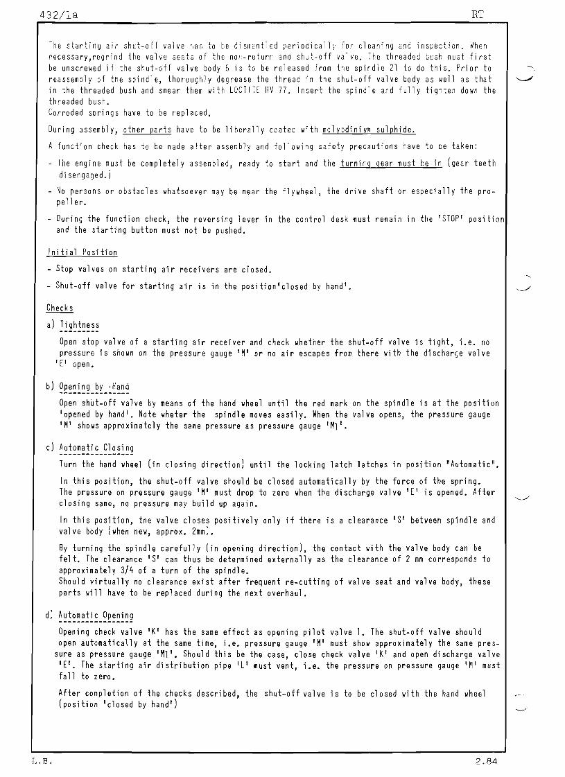
SULZER Group: 432
STARTING AIR SHUTOFF VALVERT Sheet: 1Cleaning and Function Check
Too 1s: Key to Drawings
Var. spanners 1 Control valve 9 Nonreturn valve seat 18 80 It 2 Control piston 10 Nonreturn valve body 19 Rod sealing ri ng 2a Contra 1 valve body 11 Compression spring 3 10 1 ring 12 10 1 ring 20 Scraper ring 4 Cover 13 Allen screw 21 Spildle 5 Guide bush 14 Nonreturn valve 22 Flange 6 Shutoff valve body guide housing 23 80 It 7 Shutoff val ve 15 Threaded bush 24 80 It
housing 16 Piston sealing ri ng s 25 Locking latch 8 Shutoff valve seat 26 Handwheel
17 Compression spring A Inner space 8 Annular space
AV C Stop D Equalizing hole E Drain valve K Check &water draining
,,,, I I
I
r 18
25
> . , . , c = = = l - I - I - - - t ~ . - . .,
A I
B i D •
~;;+;;;;;~':#=~~=+S
,VAF',,~ 15
1~~~"J=-16
17 C
2~.
6
14
13
12
11 10
9
-~--------15
4
r 3
Hand geschlossen
BY HAND \ . ~ - - = = = - - - I - " * = f - - -
va1ve L Starting air distribution
pipe AV Air to the starting air
valves
M. Ml Pressure gauge S Clearance (approx. 2 mm)
gezeichnet fur RT58
DRAWN FOR RT58
von
CLOSED Automat \... \-~===4 26 ,
AUTOMATIC von Hand / ' * = - - ~ - - i I=:±:..::r--.. --=7geoffnet __OPENED BY HAND 0-107.197.033
r p
-----------------
432/1a RT
The starting air shutoff valve r,as to be dismantled periodically for cleaning and inspection. When necessary,regrind the valve seats of the nonreturn and shutoff valve. The threaded bush must first be unscrewed if the shutoff valve body 6 is to be released from the spindle 21 to do this. Prior to reassembly of the spindle, thoroughly degrease the thread in the shutoff valve body as well as that in the threaded bush and smear them with LOCTITE HV 77. Insert the spindle and fully tighten down the threaded bush. Corroded springs have to be replaced.
During assembly, other parts have to be liberally coated with molybdinium sulphide.
A function check has to be made after assembly and following safety precautions have to be taken:
The engine must be completely assembled, ready to start and the turning gear must be in (gear teeth
di sengaged.)
No persons or obstacles whatsoever may be near the flywheel, the drive shaft or especially the pro- peller.
During the function check, the reversing lever in the control desk must remain in the 'STOP' position and the starting button must not be pushed.
Initial Position
Stop valves on starting air receivers are closed.
Shutoff valve for starting air is in the position'closed by hand'.
Checks
a) Tightness
Open stop valve of a starting air receiver and check whether the shutoff valve is tight, i.e. no pressure is shown on the pressure gauge 'M' or no air escapes from there with the discharge valve
'EI open.
b) Openi ng by ,Hand
Open shutoff valve by means of the hand wheel until the red mark on the spindle is at the position 'opened by hand'. Note wheter the spindle moves easily. When the valve opens, the pressure gauge 'M' shows approximately the same pressure as pressure gauge IM1'.
c) Automatic Closing
Turn the hand wheel (in closing direction) until the locking latch latches in position "Automatic".
In this position, the shutoff valve should be closed automatically by the force of the spring. The pressure on pressure gauge 'M' must drop to zero when the discharge valve 'E' is opened. After closing same, no pressure may build up again.
In this position, the valv.e closes positively only if there is a clearance'S' between spindle and val ve body (when new, approx. 2mm).
By turning the spindle carefully (in opening direction), the contact with the valve body can be felt. The clearance'S' can thus be determined externally as the clearance of 2 mm corresponds to approximately 3/4 of a turn of the spindle. Should virtually no clearance exist after frequent recutting of valve seat and valve body, these parts will have to be replaced during the next overhaul.
d) Automatic Opening
Opening check valve 'K' has the same effect as opening pilot valve 1. The shutoff valve should open automatically at the same time, i.e. pressure gauge 'M' must show approximately the same pres-
sure as pressure gauge 'Ml'. Should this be the case, close check valve IKI and open discharge valve 'EI. The starting air distribution pipe 'LI must vent, i.e. the pressure on pressure gauge 1M' must fall to zero.
After completion of the checks described, the shutoff valve is to be closed with the hand wheel (position 'closed by hand')
~
~
L.B. 2.84

SULZER Group: 453RUNNING DIRECTION SAFEGUARD
RT Sheet:Inspection and Function Check 1
Tool s:
Various spanners
13 12
11 10
9
60
8
15 16
17
3
I
2 1
II
1- 107.195.548
~ey to Drawing
1 Special bolt 2 Dr i vi ng disc 3 Driving wheel 4 Coupling element 5 Housing
6,6a Bolt bearing 7 Sl eeve 8 Rotary val ve 9 Bo 1t
lD Spring plate 11 Cover 12 Compression spring 13 Spring plate 14 Pointer 15 Split pin 16 Castellated nut 17 Gasket 18 Stop pin 19 Bo lt F Sliding faces Y Air gap
HI-HI
L.B. 2.84

453/1a
Oi smantl i nq procedure
The running direction safeguard does not need any maintenance in service. HOllever, lie recommend that it be dismantled during a major overhaul (every 4 years). The co~ponents should be cleaned and checked ~
for lIear, in particular the sliding faces 'F'. Roughened sliding faces can possibly be reconditioned by careful polishing. By loosening the oil pipe connections and the four bolts 19, the complete running direction safeguard can be removed. For the inspection of the rotating parts proceed as follolls:
Remove the pointer after first knocking out the heavy type dowel pin.
Unscrew the bo 1ts 9 whi ch hol d dOlln the cover 11 and remove thi s along wi th gasket 17.
Pullout the split pin 15 which locates and secures the castellated nut 16 and unscrew the nut.
Remove spring plate 13 and 10 along lIith compression spring 12.
The special bolt 1 can now be knocked out with a couple of light taps on the head end and removed.
Driving disc 2 and coupling element 4 as well as the driving gearwheel 3 between, can nOli be pushed down from the rotary valve 8. This dismantled situation makes a complete inspection of the ball bearings 6 and 6a as well as the coupling element possible.
Hints for Reassembly
The parts prepared for reassembly should be oiled slightly, in particular the faces marked 'F'. With sliding faces overhauled and any sharp edges removed, proceed for reassembly as for dismantling, but in reverse order. The air gap 'VI must not be 1ess than 2 mm. If it is less, the driving di sc 2 and the coupling element 4 must be machined to restore the original air gap of 4 mm.
The two spring plates 13 and 10 are not interchangeable. Fit first the one named 'inner spring plate' 10. The compression spring 12 follows and finally the outer spring plate 13 which is compressed to the dimension 'X' about 63 mm by tightening the castellated nut 16. Lock with split pin 15.
Before fitting the cover 11 with gasket 17 on the housing 5, turn the rotary valve 8 with a spanner (on the castellated nut) several times to and fro. This should be possible without much effort. The rotary valve should allow turning by about 50
0 from one stop to the other, this can also be checked
on the cover 11 where the mark on the pointer must coincide with the marks on the cover in 'Forward' and 'Reverse' during the function check.
Function Check
After completing the assembly of the running direction safeguard its function should be checked as fo 11 ows:
The engine (ready to start) has to be turned through one revolution 'Ahead' and 'Astern' with the turning gear. When doing so, move the reversing lever on the control desk from 'Ahead' to 'Astern' and back and observe if the shutdown servomotor reacts immediately and if the fuel regulating linka- ge is pulled in the '0' direction when the turning direction of the engine does RQi coincide with the position of the reversing lever (watch the position of the setting plate positions on the fuel injec- ti on pumps).
If the cutout servomotor does not immediately move to position '10' although the engine sense of ro-tation corresponds to the position of reversing lever, the reasons for this may be that the control air pressure is too low to act against the spring force in the shutdown servomotor.
T • R. ?,R.1
r
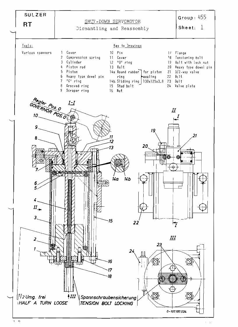
SULZER
RT SHUTDOWN SERVOMOTOR
Dismantling and Reassembly
Group: 455
Sheet: 1
Taa1s: Key to Drawings
Various spanners 1 2 3 4 5 6 7
8 9
Cover Compression spring Cylinder Piston rod Piston Heavy type dowel pin 'Of ring Grooved ring Scraper ring
10 Pin 11 Cover 12 la' ring 13 Bolt
14, R'"'d r"bb'~f,r pi,t,o ring sealing
l4b, Sliding ring l30x125x3.8 15 Stud bolt 16 Nut
17
18 19 20 21 22 23 24
Flange Tensioning bolt Bolt with lock nut Heavy type dowel pin 3/2way valve Bo It Bolt Valve plate
II
I
19 21
III
1/2 Umg. frei +111 Spannschraubensicherung V HALF A TURN LOOSE TENSION BOLT LOCKING
, 11__
3 15
2
1 2'
16
22 ~
T 0

455/1a RT
Normally the shutdown servomotor does not need any maintenance. Should, however, considerable leakage from the pressure chamber be detected, the grooved ring and/or the piston sealing rings must be re- placed. The servomotor piston 5 must be removed to do so. An inspection of all the internal parts should be carried out during the 4year survey in any case.
Di smantl i nq Procedure
Shut off control air and vent the piping system.
Release pipe connections to the valve plate 24 and, after removing the four bolts 22, remove the complete shutdown servomotor from its mounting.
Remove piston 5 and cover 1 with spring 2 together as one unit after unscrewing the four nuts 16. The spring tensioning bolt 18 remains secured by the tensioning bolt locking arrangement during re- moval of the piston. Should the spring 2, loaded between piston 5 and cover 1, also have to be released from the latter, it has to be unloaded with the aid of the tensioning bolt 18 after unscrewing the two bolts 23 and removing the tensioning bolt locking arrangement.
Note: The bolt 19, predrilled and secured with heavy type dowel pin 20, should not be removed during dismantling. It serves only as a stop and limits the maximum engine power as determined during engine acceptance trials.
Inspect the individual parts after thoroughly cleaning them.
Damaged parts have to be replaced by new ones. Pay particular attention to the parts 7,8,9 and 14 which are subject to wear.
Before finally reassembling the shutdown servomotor, lightly oil all its parts. Check without spring that piston with piston rod move freely in the cylinder.
Reassembl y
Assembly follows in the same way as dismantling but in reverse order.
The piston is fitted with cover and spring outside the cylinder, the latter pretensioned and then pushed into the cylinder.
Note: When tensioning the spring, screw in the tensioning bolt 18 up to the end of the thread and then turning it back through about half a turn. Now the tensioning bolt locking arrangement (hexago-nal tubel can be fitted.
After connecting up the valve plate and control air pipes, check the function of the shutdown servo-motor by filling and venting the control air system several times.
In the,vented condition the shutdown servomotor should bring the fuel pump regulating linkage to Pos. '0'.
T D

'./
SULZER Group: 510Woodward Governor PGA 200
RT Installing, Removing and Maintenance Sheet: 1
Tools: Key to Illustrations
1 Screwdriver 1 Governor cover Var. spanners 2 Pneumatic speed control
3 Accumulator 4 Connection / oil to cooler 5 Oil drain plug 6 Adjusting screw for needle valve 7 Connection '2' / oil from booster 8 Knob for manual speed setting 9 Charge air connection
10 Dip stick for checking oil level 11 Governor output shaft 12 Oil filter 13 Cap for overspeed test device 14 Oil filling connection 15 Connection '1' / oil from booster 16 Connection / oil from cooler 17 Connection / oil to booster 18 Oil drain plug 19 Governor drive shaft
07813076-5
Installing and removing the governor on the engine
When lifting off the governor or placing it on the engine, care has to be taken to ensure that the splines on the lower end of the governor drive shaft to not get damaged. Furthermore, it must be possible to insert the shaft without jam-ming when fitting the governor onto the drive.
Pipes and linkages must be connected up with-out stressing them.
When the governor, oil cooler and booster are separated from each other, care has to be ta-ken to prevent any dirt from entering the oil pipes and their connections.
For checking
The governor positions '0' and '8' must be checked immediately after connecting the fuel pump linkage to the governor; They must absolutely correspond to the positions on the control plate on the fuel injection pump. the V.LT. indicator must then stand in position '0'.
L.B. 7.86

510/1a RT
Maintenance
Information about maintenance work, maintenance intervals and repairs can be gained from the WOODWARD bulletin which is supplied separately with the governor.
Repairs on the governor should be carried out by WOODWARD experts only (or by specially trained personnel). It is, therefore, advisable to keep on board a complete spare governor, carefully adjusted to suit the engine, which allows immediate replacement if necessary. The defective governor should be returned to a WOODWARD service agency for repair. It is imperative that a copy of the governor adjustment records of the engine be handed to the agency as the governor will have to be re-adjusted according to these records.
18
Oil change
Under favorable service conditions, the oil can remain in the governor for 6 months (approx. 3000 hours) or even more. Should, however, the oil become blackish or show signs of aging, it must be changed immediately.
The used oil of the governor must be drained when hot by unscrewing the oil drain plugs 5 and 18 with the engine s top p e d. The oil in the oil cooler as well as in the booster must also be drained.
Where an oil filter is fitted (governor with charging protection), remove the screw up on the housing 12 and withdraw the filter element. This should be sloshed about in paraffin or clean fuel and then gently blown out with compressed air. Replace the filter straight away since it is essential that it be in place when carrying out the following flushing procedure.
"'----'
19 0781 3076-7
iA 1986
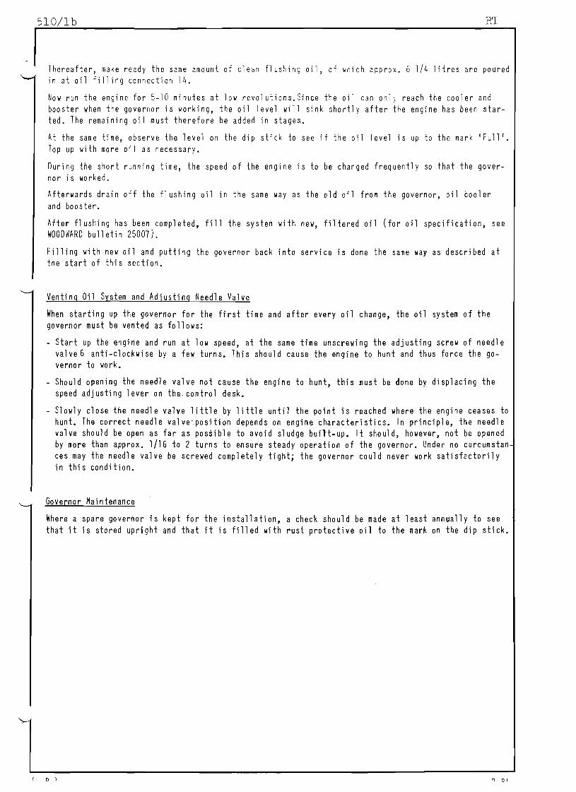
510/1b RT
Thereafter, make ready the same amount of clean flushing oil, of ~hich approx. 6 1/4 litres are poured in at oil filling connection 14.
Now run the engine for 510 minutes at low revolutions.Since the oil can onl~ reach the cooler and booster when the governor is ~ o r k i n g , the oil level will sink shortly after the engine has been started. The remaining oil must therefore be added in stages.
At the same time, observe the level on the dip stick to see if the oil level is up to the mark 'Full '. Top up with more oil as necessary.
During the short running time, the speed of the engine is to be changed frequently so that the gover
nor is worked.
Afterwards drain off the flushing oil in the same way as the old oil from the governor, oil cooler
and booster.
After flushing has been completed, fill the system with new, filtered oil (for oil specification, see WOODWARD bulletin 25007).
Filling with new oil and putting the governor back into service is done the same way as described at the start of this section.
Venting Oil System and Adjusting Needle Valve
When starting up the governor for the first time and after every oil change, the oil system of the governor must be vented as follows:
Start up the engine and run at low speed, at the same time unscrewing the adjusting screw of needle valve6 anti-clockwise by a few turns. This should cause the engine to hunt and thus force the governor to work.
- Should opening the needle valve not cause the engine to hunt, this must be done by displacing the speed adjusting lever on the control desk.
Slowly close the needle valve little by little until the point is reached where the engine ceases to hunt. The correct needle valve~position depends on engine characteristics. In principle, the needle valve should be open as far as possible to avoid sludge built-up. It should, however, not be opened
by more than approx. 1/16 to 2 turns to ensure steady operation of the governor. Under no curcumstan ces may the needle valve be screwed completely tight; the governor could never work satisfactorily in this condition.
Governor Maintenance
Where a spare governor is kept for the installation, a check should be made at least annually to see
that it is stored upright and that it is filled with rust protective oil to the mark on the dip stick.
(, 0 , ~ 01

:/'5
SULZER
RT
Var. spanners
7
S ~ F E T Y C U T - O L ~ DFVICE
Maintenance, Function Check
Key to Drawings
Group: 530
Sheet: 1
1 Cutout yoke guide 2 '0 1 rings
3a Round rubber ring }fOr piston 3b Sliding ring sealing 3c Round rubber ring }fOr rod 3d Sliding ring sealing 4 Compression spring 5 Castellated nut with
split pin 6 Cover 7 Cover plate 8 Screwed rod with nut 9 Cylinder (upper)
8
10 Piston 11 ~ush
12 3/2way sol enoid val ve 13 Valve plate 14 Intermediate piece 15 Cylinder (lower) 16 Pull rod 17 Fuel pump body 18 Guide bush 19 Cutout yoke K Piston underside L Air supply chamber
St Control air pipe
10 K 11 12 13
St
14 L
16
17
18
1-107.195545
~ s a rule the safety cutout device requires no maintenance. Should, however, excessive air leakage from either the air supply chamber 'L' or from space 'K' (piston underside) be detected, the defective '0' rings, pi stan or rod sealing rings must be replaced by new ones. As opposed to the other parts of the air cylinder, the pull rod 16 can only be removed from below. The fuel injection pump block must first be lifted. Before starting any maintenance work which may be necessary, fully release the control air pressure, vent the system and disconnect the control air pipe 'St' from the valve plate. When the air cylinder is being dismantled, all the parts of this unit have to be cleaned and their condition checked. If the compression spring is corroded it must be replaced.
Lightly oil the cleaned parts prior to assembly. A function check has to be carried out after assembly and after putting the control
air system under pressure. Operate the electri cal emergency stop button 5.25 (see the Schematic Layout of the Engine Control System, Groups 400-20 and 530 of the Service Instructions Manual). As a result, the cut-out yoke will be pulled up to its stop on the underside of the fuel pump body,
Warning! Never press the emergency stop button as long as work is being done with either the hands or tools on the underside of the fuel pump body.
L. ~. 2.84

SULZER FUEL INJECTION PUMPS Group: 551
Setting and Checking the Control with V.I.T.RT
(Variable Injection Timing) Sheet: 1
Too 1s: Key to Illustrations
1 Tensioning tube 94534 1 Spill valve seat 28a VIT indicator
1 Device for measuring 94552 2 Valve seats for suction/ 29 Clamp screw
2 Devices for measuring 94554 delivery valves 30 Pointer to setting shield
3 Special spanners 94555 3 Relif valve 31 Graduation to item 30
2 Special spanners 94557 It Indicator to relief valve 32 Load indicator
1 Torque wrench 94559 5 Hand grip to manual shutdown 33 Speed governor
w.h~x.pl ug spanner 6/6a Pressure nipple (long) & (short) 34 Regul ating linkage to suc-
and extension 8 Push rod with guide bush tion valve
1 ~ithdrawing device 94561 9 Cover 35 Regulating linkage to spill
1 Wi thdrawing devi ce 94564 10 Pin (short) va 1ve
1 Special spanner 94571 11 Pin (long) 36 Setting cam of curve seg-
1 Ci rcul ar di sc 94581 12 Compression spring men t
1 Grease gun 13 Compression spring 70 Spacer 14 Plunger and 71 Screws
14a Pl unger gui de 72 Spacer
15 Waisted screw 73 Nut
16 Speci a1 screw 74 Puller rod Important! 17 Stepped throttle 74a Disc
18 Connectors 75 Safety gri p Before starting preliminary
19 Fue1 pump body 76 Setting screw measures to carry out chec-
20 Double nipple 3. 12 Fuel 1everking and setting work on the
21 Orai n screw 6.03 Shutdown servomotorfuel injection pumps, the en-
22 Threaded pl ug E Fuel inletgine must be changed over to
23 Threaded plug P To the injection valvesDiesel fuel before shutting
24 Regulating tappet R Fue 1 returnit down!
25 . Shuto ff valve Ul Spill valve to pump 1
26 Sh~t-off val ve U2 Spill valve to pump 2
28 Injeciion start setting lever 01 Pressure valve to pump 1
02 Pressure valve to pump 2 Sl Suction valve to pump 1
52 Suction valve to pump 2 K Hand 1ever
A) 0 ire c t ion san d perm iss i b1e 0 e v i a t ion s
The correct adjustment of the fuel injection pump control is extremely important. C h a ~ g e s to the ef- fective delivery strokes may only be attempted when on occasion of checks, unadmissible deviations from the recorded data of the timing records are established. The timing records which will be often mentioned in this description are handed over to the customer together with the test protocol.
a) Replacement of parts
When parts of the fuel injection pumps (f.i.pumps for short) are being replaced, which influence the fuel injection control in any way, then the f.i. pump controls must be checked and if necessary reset in compliance with the values of the timing records.
b} Cutout Checks
In order to ensure that the engine can be shutdown at any time and 'can never' run away' respecti-vely the various cutout checks must be carried out after the engine has been set anew. (See para-grap h 'E I ) •
c) Setting Data in the Timing Records
The decisive setting data of the fuel injection pumps and fuel cams are established for a speci- fied setting dial position and entered in the timing records. These are: Idl e stroke. begin of injection/total stroke. end of injection The effective plunger stroke entered in the timing records results by necessity from the idle stroke and the total stroke.
L. B.
L

551 /l a RT
d) Effective delivery stroke (in mm)
The effective delivery stroke is set by modifying the length of the regulatir,g tappet 24 for t~e
suction and spill valves. In this manner shortening the regulati"g tappet produces an increase in the effective delivery stroke, and lengthening the regulating tappet produces a reduction in the "" effective del ivery stroke.
~ ~ l ~ ~ ! ~ ~ 2 = ! ~ ~ = ~ ~ 2 ~ l ~ ! ~ ~ 2 . ! ~ ~ ~ ~ ! = a ~ = ~ a ~ . ~ . ~ . 2 = a ~ ~ ~ ~ ~ ! ~ S ~ = ~ ~ . ! ~ ~ ~ ~ ~ ~ ~ ~ ! Equal effecti ve del i very strokes on all f. i .pumps are necessary to obtai n bal anced power outputs on all the cyl i nders; For thi s reason the measured val ues of the i ndi vi dual f. i. pumps have to be com-pared with each other.
The maximum admissible deviation between the biggest and the smallest effective delivery stroke on individual cylinders is O,2mm, and the deviation of the effective delivery stroke to the values in the timing records should not exceed ~ O,lmm.
e) Beqin of Injection
The begin of injection (<t before or after T.D.C.) of a fuel injection pump may only be altered by shifting the fuel cams and not by resetting the regulating tappet of the suction valve. The devia-tion to the timing records shall not exceed ± 0.3
0 •
f) Equalizing the maximum Cylinder Pressures
The equalizing of the ~aximum cylinder , r ~ , s t l r e s may· only be·brought about by turning the fuel cam and not by changin~ the lengths of regulating tappets of suction and spill valves (condition is equal compression pressures). Directions on the turning of fuel cams are given in Group 421.
g) Spac6rs for Fuel Del ivery Reduction
While setting and checking the f.i.pumps ~ spacers may be inserted for delivery reduction. Di-rections to this effect are given under group 551 in the operating instructions.
B) Pre par a t ion s
1. Engage turning gear.
2. Close shutoff valve for starting air with the hand wheel (Item ="shut by hand").
3. Close shutoff cock of fuel feed and return piping, immediately behind the f.i.pump.
4. Slightly loosen the drain screw 22 arranged at the side at the height of the stepped throttles to drain the fuel from the pump body.
4a. Removing the Circuit pressure regulating Valve.
5. Remove cover 9, springs and pressure valves (above the pump plunger). Remove also the cover above the suction and spill valves, unscrew the pressure nipples 6 and 6a and remove springs and valves (Fig. 'E'). ''"
6. Wash suction and spill valves as well as their valve seats in kerosene or similar. Check that the valves slide easily in their guides and that the valve seats are undamaged. If necessary recondi-tion the seat faces by careful grindingin or replace the valves. Fit suction and spill valves -wit h 0 u t their s p r i n g s again and tighten their pressure nipples 6 and 6a firmly wi th the speci al spanner 94571 to 300 Nm (31 mkp).
7. Check whether the spacers 70 and 72 of the dial gauge holder slide well and the dial gauge func-tion properly. If so, mount the dial gauge holders and screw them tight. (See Fig. 'G'l.
8. Remove fuel lever 3.12 from pos. F.S. By this the air cylinder to the governor/linkage connection is vented and the shutdown servomotor 6.03 moves to operating position. (see. Fig. 'B' l.
9. Remove the lock screw locking device from the shutdown servomotor 6.03, and turn the lock screw completely out of the piston rod. Place the tensioning tube (tool No. 94534) onto the same lock screw. Screw the lock screw with the tube in till the stop. (See also Fig. 'B'; take note of the remark thereon).
10. Close three shutoff valves marked with 25, in the console of the control air supply, and open the two shutoff valves 26 for the air container drainage. (See Fig. 'AI).
I R 6.86

551/lb RT
11. Start 1ubricating oil p u ~ p s f Jr cearinQs and crossreads and set pressures for normal operation. (Set-
ting values on sheet 025 od uescr;ption and operating instructions).
12. Bring reversing lever or the , 1 u ~ i l iary manoeuvring stand to 'AHEAD'. The pin No. 12 in the Synoptic
panel may not project outllard (c'leck by 1ightly pressing the pinJ.
13. Using lever 28 bring the pointer above the indicating plate Start of injection 28a (possibly still
pointing on), position '0'. To make this adjustment possible, loosen the clamp screw 29 and move the
injection start setting lever 28 in the required direction. Retighten the clamp screll 29.
14. For RT 5868768484M remove the shifting cam fitted to the V.I. T. segment. For RT 52 and 62 remove
the curve segment and fi t ci rcul ar di sc 94581, for runni ngi ,1 of nell engine parts. Thi s ensures that
the roller of the V.I.T. rests on the zero circle.
15. Notchin the emergency fuel lever 3.12 (of the auxiliary manoeuvring stand) into the fuel linkage
and place it into the position '8', required for the checking.
16. The V.I.T. indicator 28a must point to nzero l1.
(3)
25
I I , . ' ~ . ; . 1 : . . !
Ir'T;~ ~
Gezeichnet fur RT 62
DRAWN FOR RT
:·r'-+-I. ,
+ "- --' ClJ-'-;; II---=- -=--~
• - I
!T:St~ull rluftversorgung I
: ' I I'! +
: I:CON r AIR SUPPLYOL "'" '!l , \"~
I l\~'~1
Dc===::-:--::::::::::::::~26
L. B. 6.86

..
551/1c RT
®
6.03
9 ~ 5 3 ~
3-107. 197. 071
Saug Uberstrom- '.lentil '.lentil SUCTION SPILL VALVE VALVE ,. ... II'" '0
fruh / ADVANCE
spat / RETARD
35
Remark!
After the checking is completed the setting cam or curve segment respectively must again be fitted in its original position; the position is ascertained by a pin. Remove the tension tube (tool No. 94534) and bring the shutdown servomotor back to its original position. The tension screw locking device (hexagonal tube) must only be placed in position after the tension screw has been loosened by abt. 0.5 turns. Articulated joints of the regulating linkage between governor and fuel irnjection pumps are equipped with grease nipples. These must be regularly lubricated with good quality ball bearing grease by a grease gun.
.>.--/.
10.85L. B.

I 551/1d
75
©C . 75
73 9"5 61~-----{l
7"""7=~~II:~~~74a
94564 /
a
/ 3-107.125.208
b
2-107.125.210
@
70
14o
14
for rerncval ~f t~e V2!~e seats ~ s e
the devi ces 94554 for del i very val· ves contained in the tool kit (see Fig. Ie'),
These are used as fcllo~s:
Push the ~i thdra~i ng rod 74 ~i t-hout any accessories right d o ~ n
through the valve body and pull it back until the spread for~ard end comes against the front end of the
valve seat.
_ Fit on disc 74a and scre~ on nut 73 but not right down yet.
Lead the safety rod 75 through the
~ithdrawing rod until its ring en-ters the slot at the upper end.
By tightening the nut 73 the valve seat can no~ be pulled out of the
pump block.
a = Arrangement of the dial gauges above the plunger (delivery val-
ve)
b Arrangement of the dial gauges above the suction and spill
valves.
?R4T P

~
~ ® E
Brennstoffeinspritzpumpenkorper FUEL INJECTION PUMP BODY
ausgeriistet mit WITH STAGNATION PRESSURE
Standdruckregulierventilen CONTROL VALVES .......... _ _ J
P-
21
8
6au 13 2 10
19
II.ll ~ f l - - l - 1 t ~ ~ I
15R
6Z
6 n
. ... . ..... ,. ............. '" ..................................................... " ........ ,... ............ .. ...............
LJl.I f !J'...,,~"''''''''''''''' 'i"" " ~ , , "J'..."""Jlt.....!Ul" ~ 11 -
~
EQUIPPED III ~
E P R-R P E ~ I t 18 t t t 18 I
52T.th. liT
I ~~
D~ U ,
23
'\\\ ~3.4i 51
~~At I ---~
~DI U,
I 23
IIII
20 t t 20
E
22 22
Q:) 0- 107. 198.866
Co
~ I ( )
';( ( (

551/1f RT
C) Res e t tin g the Injection Pumps
The following checking data are to be taken from the timing records. Then carry out the following adjustments according to these:
1 Setting shield position (normal '8 1 )
2 Idle stroke in mm = 'a' 3 Begin of injection in 4 a before or after 1.D.C. 4 - Total stroke in mm = 'b ' 5 End of injection in4° after 1.D.C. 6 Effective plunger stroke = fbI 'a'
Carry out preparations as per Section B ).
Setting of the Effective Delivery Stroke
1. Turn the engine until the cam roller of the injection pump to be adjusted lies on the cam peak. Place the dial gauge onto the suction valve, which is now closed, and set it to 0 (see Illus. 'GI,
Fig. 1).
2. Turn the engine 'astern' until the roller of the injection pump to be adjusted lies on the base circle of the cam. Install the dial gauges above the plunger and above the now closed spill valve (U) and, with a certain amount of pretension, set them to 0 (see Illus. 'G', Fig.2).
3. Rotate engine crankshaft 'AHEAD' until the dial gauge on the plunger has reached the value of the idle stroke 'a'. (For value refer to timing records).
4. Adjust the regulating tappet of the suction valve (S) so that the dial gauge on the suction valve indicates 0.02 mm. (When taking the reading the tensioning nut of the respective regulating tappet must already be firmly tightened!).
This position signifies:
the suction valve shuts = begin of injection (see sketches 'G' Fig. 3)
5. Read off the flywheel gradation the crank angle in 4 0 before and after T.o.C. and compare rea-
dings with the values in the timing records. If necessary shift fuel cam 'forwards' or 'backwards'. (Pl. refer to group 421 sheet 1d), for di recti ons.
6. Turn engine crankshaft further 'AHEAD', till the dial gauge on the plunger shows the dimension of the required total stroke 'bl, note the indications in the timing records).
7. Re.set the regulation tappet of the spill valve with spanners (see sketch 'F') so that the dial gauge on the spill valve lUI shows 0.02 mm. This position signifies:
the spill valve opens = End of injection (see sketch 'G' Fig. 4)
8. Read off the flywheel gradation the crank angle in 4 0 after T.o.C. and record it (for tolerances
pl. refer to 551/1 section A).
®
u 2 t07. t97. 066
L. B. 6.86

551/1g RT
0) Checking the ruel Injection P u ~ o s
The same setting values as given on sheet 55l/1f (setting injection pumps) ~ust be used.
Carry out preparations in accordance with section B).
®
CD
Checking the Begin of Injection, End of Iniection and of the effective Plunaer stroke
The description below applies to IAhead' r·otation,
1, Turn the engine until the cam roller of the fuel pump to be checked rests on the peak of the cam. Fit the dial gauge over the now closed suction (S) and set it to 0 (see 111us. IG', Fig. n.
2, Turn engine in 'astern', until the cam roller rests on the base circle of the cam, Fit the dial gauges over the plunger as well as over the now closed spill valve (U) and adjust to 0 with a slight pre-tension (see Illus. IG', Fig, 2).
3. Turn engine crankshaft 'ahead' until the dial gau-ge on the suction valve '5' shows only 0.02 mm. This position signifies:
The suction valve is closing & begin of iniection (see sketch' G' Fi g. 3)
107.197.06'
E E N o c'
~
L. B. 6.86

551/lh RT
4 Rea d the i d1est r 0 ke 'a I 0 f': +,~ e~: i J ~ Ccue e crt ref ue1 p1, un 9era nd r ecor d : ~ e \' 3 1Ij e. ~ ed c f ~ t" e
f1 ywheel gradati on the crad, "',,,;1 e i c ~ 0 ~efJre or a Her T.0. C. a~d record it.
5. Turn eng i nee ran cs haft f AHEi. C1 " ,~ til the di 31 9aug eon the spill val ve (L:) show sO. i} 2 m~ 0 f s t r 0 ke.
This position signifies:
The spill valve opers " end of icjection (see sketch 'G' Fig. 4)
5. Read off the fly'Wheel gradation He c r 2 n ~ 3ngle for 'end of injection in 0 after I.D.C. ard record
it. Read also the value off the dial gauge o~ the fuel plunger and record this as stroke fb'. i ~ e ef-
fective plunger stroke is arrived at bv substraction of 'b' 'a' (for admissible tolerances p1. con-sul t 551/1 section A).
7. Finally, carry out the cutout c ~ e c k s (see section 0.
E) Cut 0 u t C h e c k s
The cutout checks for the i n j e c t i o ~ pumps are of major importance and must therefore be carried out
after every resetting of the injection pumps. We further recommend that these checks also be ~ade af-
ter every major overhaul of the 1njection pumps.
The following points have to be checked:
1. Checking the Fuel Injection Pump Valves at setting Shield PdS. '0'
With the setting shield position '0' suction and spill valves of the same fuel injection pump may
n eve r be closed at the same time, i.e. when one valve is closed the other must be open, so that
a fuel injection is excl uded. At the moment that the suction valve shuts, the spill valve must be 1 if-
ted by the value entered in the timing records.
2. Checking the '0' positions
The '0' positions on the load indicator and the setting shield on the fuel injection pumps must cor-respond.
3. Checking the manual Cutout on the Injection Pumps
When the injecti on pump dri ves are cut out with the manual 1ever 'K' a vi si bl e cl earance must exi st
between the timing roller and the head circle of the fuel cam, (see sketch 'H'). For instructions on
the cutting out and in of fuel injection and exhaust valve actuator pumps pl. refer to the instruc-tion book.
4. Checking the Safety Cutout Device
The instructions on sheet 011 of the operating and instruction book must be followed without fail.
F) Install ing the Val ves after a Check
The follo'Wing points must be observed when fitting the valves:
All the valves and springs must be dipped in clean fuel or parafin before fitting them.
If the pressure nipples marked ** 'Were once more removed after the resetting, they must also be rin-
sed in clean Diesel fuel and then tightened with the special spanner tool No. 94571 to 300 Nm (31 ili) (see sketch 'E').
During the assembling tighten the screws 15 marked 'With * carefully crosswise and in small steps
with 60'Nm (6.1 mkp) with the torque wrench 94559. Use molycote G paste as lubricant (see Fig. 'E').
G) Fitting the Stepped Orifices
When a pump body has been replaced, a check must be made to see if the stepped orifices are fitted in
the new part. It may be necessary to use the ones from the old pump body. When fitting them, please no te the following:
Both the stepped orifices are of identical design and can be used in either position. They have
first to be located with the drain pl ugs 21 and then tightened with the special bolts 16.
L. B. 5.86

RT551/1i
®
I Brennstoffpumpe ausgeschaltet
FUEL PUMP OUT OF OPERATION
5
--""'----1--- E E
C\l II
II ~/ f II-II
::"J v/~BrennstoffPumpe eingeschaltet ; • [ / FUEL PUMP IN OPERA TlON
I' ..s:&
II
4-107. 217.134
, Q ?R7

2
SULZER Group: 551FUEL INJECTION PUMPS
RT Lapping the Sealing Faces for the Covers Sheet:of the Suction, Delivery and Spill Valves
Tools: Key to Drawings
Lapping mandrel 94566 19 Fue 1 i nj eeti on pump A Assembly cover Lapping mandrel 94567 bod y B Lapping the sealing face on Centering ring 94565 9 Covers for the valves the pump body Torque wrench with 6/7 Backing bush C Lapping the sealing face on wi th hex. socket 94559 the cover
SF Flat sealing face SFl Sealing face
00
10' with slope of
In case of leakage between cover and pump body, although the Allen screws have been tightened to the prescribed torque of 60 Nm (6 mkp), it may be possible that the sealing faces are no longer in perfect condi bon.
Additional tightening of the screws will not solve the problem; the seal ing faces will have to be dressed.
Slight damage can be rectified with the lapping mandrels (Nos. 94566 and 94567) contained in the tool kit.
For lapping the flat sealing faces on the pump body, the tool is to be used as shwon on Fig. 'B'.
In order to avoid that, after a time, a groove is ground in the lapping face of the tool, the lapping mandrel must be moved in circles over the whole sealing face and not only around its own axis.
00
The cover sealing face and the corresponding lapping mandrel 94567 are tapered by la' (see Fig. IC')
The mandrel 94567 for lapping of the cover sealing face (Fig. 'G') is guided by centering ring 94565 so that it can only be rotated around its own axis.
In case rectification of the lapping face of the tool becomes necessary, the above taper must be borne in mind.
Very fine lapping paste must be used for lapping.
Attention: At all cost, prevent lapping paste from getting into the pump body!
The threads of the Allen screws must be coated with Molykote paste G before being screwed in. The screws must be tightened crosswise and in even ~tages (a total of 60 Nm (6 mkp).
©
60Nm 6mkg 94566 ® 94567
2107.072.383

3
SULZER Group: 551
- ~',' ~ ~~- 1--'- ~ -
... '<L ._ ..... ~ _. ~ .. ,
RT CheckiY1[ S8tting cf the Relief 1Jalve Sheet:
Tools: Key to Drawinos
Injector test 94272 1 Relief valve B Ci rc 1i P stand lLl0Rh~GE" 2 Valve needle 9 Spri ng pl ate Mounti ng angl e 94273 3 Stop ring 10 Closing plug bracket 4 Distance ring 11 Ball o 12 Hosepipe 94275 5 '0 r ri ng 12 Flushing valve Testing head 94277 (0 66.27 x 3.53) 12a Spindle for 12 Speci al spanner 94556 6 Belleville A Delivery pipe Sl i de gauge spring washers connection
(11 off) H Pump 1ever 7 Thrust washer MA Pressure gauge
(0 1600 bar)
o y x
11
10
9
8
7
3-107.195.513
Before dismantling a relief valve for overhaul (grinding in of the valve needle), the distance 'X' must be accurately measured and the figure recorded as IXI. The distance ring 4 must be pressed against the stop ring 3 by the closing plug 10. After grinding the valve needle 2 into the seat of the valve housing 1, all the parts must be thorough- ly cleaned, the valve needle 2 lightly oiled and parts 6,7,9 and 11 sprayed with Molybdenum Disul- phide (MoS2). During assembly, care must be taken that the Belleville spring washers 6 are correctly positioned (see Fig. IAI)' The distance ring 4 should not yet be fitted. Tighten the closing plug 10 until the distance 'X' is about the same as before dismantling.
L.B.

RT
@ 12a
Metallische Dichtflachen
METALLIC SEALING FACES
12
94275
94273
Gezeichnet fur RT58
DRAWN FOR RT 58
1
2-107.197.098
5.8!.L. B.
94556

551/3b RT
© A
94277
94273
94272--+-
MA
gezeichnet fur RT 58
DRAWN FOR RT 58
For testing and setting the rel ief valve for the fuel pump use the tool No. 94272 which belongs to the tools of the L'ORANGE injector test stand.
Use connection rAJ (see Figs. 'C') for this together with the right hand pump lever 'H' and pressure gauge 'MAl (01600 bar).
Work Procedure for Setting the Iniection Pressure
Fit the testing head 94277 to the mounting angle bracket 94273 and bolt it down.
Screw the relief valve 1 into the testing head (without joint) and tighten it with special spanner 94556.
Connect high pressure hose to connection 'A' and head it to the testing head.
Once the connection has been made, the flushing valve should be opened a little by spindle l2a.
Operate pump lever 'H' until the pressure chambers are filled and the diesel oil escapes bubblefree. Close flushing valve spindle 12a.
Operate the pump lever at the same time as watching the pressure gauge 'MA' to see at what pressure the rel i ef val ve opens. Correct opening pressure = 1150 bar.
The prescribed pressure can be set by moving the closing plug 10. Measure the distance 'X' and not it as 'XlI (Fig. 'AI).
Now reduce the height 'yr of the distance ring by the difference between the distances IX1' minus 'X'. Finally, reassemble the relief valve (this time with distance ring 4) and tighten the closing plug 10 until it is fully down on the distance ring 4.
Carry out another check of the opening pressure on the fully assembled relief valve. When this is correct, the valve can be refitted in the injection pump body.
Note: Before screwing the relief valve into the injector pump body, check that the sealing faces of the valve housing 1 and the injector pump body are clean since the sealing of these faces is metallic i.e. wit h 0 u t sealing ring! Use the special spanner 94556 to tighten the relief valve (see Fig. 'B').
4-107.197.085
L. B. 2.89

SULZER
RT FUEL INJECTION PUMPS
Checking and Setting the Static Pressure Regulating Valve
Group: 551
Sheet: 4
Key to III ustrati onsTool s:
Valve test stand 94272 11'ORANGE"
Mounti ng angl e 94273 Hose pi pe 94275 Torque wrench 94559 Setting device 94572 Vernier, slide caliper
o 1
I
: I II II I I
:1':II II 'I " ~ I
'I
t=
7
1 Blow through valve
la Spindle 2 Valve casing 3 Screw plug 4 Connecting piece 5 Valve body 5 Stop sleeve 7 Setti ng di sc
94273
~ I
8 Compression spring 9 Waisted screws
10 Static pressure regulating valve A Connection for hose H Pump 1ever
MA Pressure gauge X Valve stroke
1
94572
gezeichnet fur RT 58 , -107, 198.892 DRAWN FOR RT 58

FOR RT 58
A
MA
94275
551/4a RT
® gezeichnet fur RT 58
DRAWN
94572
Checking and Setting the Opening Pressure
Mount the setting device 94572 on the mounting angle 94273 and fasten firmly.
Fit the valve casing (cover) 2 with waisted screws 9 on the device 94572 in such a way, that the connecting piece 4 can be fastened as shown in Fig. I AI.
Fasten the connecting piece 4 without the stop sleeve 6 onto the valve casing 2 with the waisted screws 9.
Connect the device 94572 to connection lA' with the hose pipe 94275. (see Fig. 'Bf).
Open the blow through valve 1 slightly with the spindle lao
Actuate the pump 1ever' H' until the pressure spaces are fi 11 ed and the Di esel oil flows out bubble free. Shut the blow through valve 1.
Measure the opening pressure on the pressure gauge 'MA' while actuating the pump lever 'HI. The thickness of the setting disc 7 must be so defined that the opening pressure is 100 bar.
Having defined the thickness of the setting disc, shorten the stopsleeve 6 to obtain a valve stroke of X 1.2 ~ 0.1 mm (see Fig. 'AI).
Fit the completed static pressure valve 10 and check once more that the opening pressure is correct (100 bar) before installing it on the engine.
1984

SULZER FUEL INJECTION PUMPS Group: 551
Tightening of a Nipple to the Plunger GuideRT Sheet: 5
Tools:
1 Impaet
1 Sl edge
wrench
hammer
94551 1
2
Key to
Pump body
Nipple
Illustration
3 Pl uger gui de
4 Heavy metallic
underlay
Marken, Nippe/ - Ausgangsste//ung
MARKS, NIPPLE STARTING POINT
Marke, Nippe/ - festgezogen
MARK NIPPLE - TIGHT
Vorschlaghammer 6kg SLEDGE HAMMER
zwei
TWO
Zahnabstande
TOOTH PITCHES
1
2
3
3 - 107. 240. 068
L. 8. 198 S

Our Recommendation for tightening a Nipple to the Plunger Guide 1n the Fuel Injection Pump Body:
Place punp body on a heavy metallic underlay.
Clean all contact faces (plunger guide pump body) with greatest care and keep them dry; only after this insert the plunger guide into the pump body.
Smear MOLYCOTEpaste 'G' on thread and pressing face of the nipple.
Push nipple over plunger guide and drive by hand into the thread in the pump body till the stoP.
Place impact wrench 94551 into toothed portion of the nipple and firm the latter up with a light ham-mer stroke.
In this position mark position on one tooth of the nipple and on the pump body (initial position for pretensioning the nipple).
Make another mark on the pump body over the second nipple tooth to the right starting from the initial position, this gives the measure for the following extremely important pretensioning of the nipple (See Illustration 551/5).
Using a sledge hammer (5 ~ 6 kg) on imp~ct wrench 94551 tighten the nipple till the rotation of the nipple has reached the premarked position (= two tooth intervals).
Attention! At the first tightening of the nipple together with a plunger guide in a new pump body. the fastening must be once more loosened and the whole tightening process repeated in order to make up the setting losses.
, 0

SULZER Group: 640CHARGE AIR RECEIVER
RT Maintenance of the Valve Grouns and Sheet: 1 Cleaning of the Charge Air Receiver
Tools: Key to Drawings
Speci a1 box spanner Cleaning container Var. spanners
94645 1 Charge air receiver
2 Relief valve 3 Dividing wall 4 Val ve groups 5 Valve groups 6 Hinged cover
(space H) 6a Hinged cover
(space p)
7
8
9 10 11
12 13 14
Closing pl ugs Valve plate
First piec, } for val veCenter piece End piece
group
Tensioning bolt Round nut (short) Round nut (long)
Cl eaning
The valve groups situated in the charge air receiver must be cleaned periodically and the cleaning intervals are determined by the service conditions. (see sheet 021/4)
The valve groups can be reached through the openings in the receiver which are closed with the bottom and inner hinged covers. Before openiog covers 6 and 6a their closing plugs 7 must be unscrewed to drain off accumulated oil (see Fig. 'AI J.
The valve screwed together to valve groups must be cleaned in a container filled with paraffin or gas oil without being dismantled. The time needed for soaking depends on how dirty they are and on the kind of solvent used. Where chemical solvents are used, care must be taken that the valve plates (steel) and valve bodies (aluminium) are not attacked. After washing, the valve groups are blown out with compressed air.
We recommend that a complete set of valve groups be kept as spares for replacement. The cleaning of the dirty valves can be tackled later during the voyage or prolonged service breaks.
L.B. 2.87

640/1a RT
Checking
Broken or cracked valve plates must be replaced by new genuine spare valve plates of the same thick-ness. The aluminium parts may have neither burrs nor cracks and their seating faces for the valve pla- ~
tes must be even.
Assembly
If a valve group had to be dismantled, the procedure for reassembly is as followsr
Assemble the valve groups loosely at first (note curvature of valve plates concave side towards the air duct (see Fig. on previous page).
Screw on round nuts 13 and 14, but do not tighten them yet.
Carefully knock the valve group with its flat part downwards onto a surface plate and moderately tighten the nuts with the special spanner 94645. If individual valve plates do not close properly, the round nuts 14 must be loosened and then tigh-tened again. Once all the valve plates are resting properly on the valve bodies, the nuts are locked and the valve groups fitted into the charge air receiver (for fitting position, see Fig. 'AI).
Relief Valve on the Charge Air Receiver
During a major overhaul, the relief valves are to be dismantled, cleaned and checked for freedom of movement. The valves are set to an opening pressure of 3.1 to 3,7 bar.
Charge Air Receiver
Next to the daily draining of the receiver, its internals should be cleaned at every piston overhaul (earlier if necessary). Only cleaning cloths and not cotton waste should be used since remaining waste threads can prevent the valves from closing.
Opportunity should also be taken to check that the receiver drain pipes and their cocks are not blocked since permanent drainage must be assured.
L.B. 5.84

------
----
6L,O/1b RT
o I-I
5
gezeichnet fUr RT 58
DRAWN FOR RT 58
.r-+--2
I I /,I I '
6 ~ V/
3
l l l ~ IlI-lll
IJl-IJl
+ Spiilluft
~-._~
-
2 107.197,002CHARGE AIR
L.B. 2.84

'""
~
'''../
SULZER
RT CHARGE AIR RECEIVER
Maintenance of the 1 ~ a t e r
Group:
Sheet:
ELm
2 Separator Elements
Tools: Key to Drawing
Var. Hand
spanners lamp
25
26 27 28 29
Water separator elements Drain pipe Special bolt Belleville washer pack Charge air receiver
30 31 32 A
Bolt Spring washer Support Space for placing a removed water parator element
se
B
C F G
Space for separated condensate Dividing wall Support fastening
Bifurcation
Water separator elements should be inspected after the first year in service. The degree of fouling found will determine the cleaning intervals for future maintenance. There should be no fouling to speak of if the suction air filters of the exhaust gas turbocharger are well maintained.
During this inspection particular attention has to be paid to the inspection of the air inlet side of the individual elements. Initially remove two elements from each group and then, depending on their con dition, also remove and clean the remainder.
Removal of the Elements
Procedure
- Open both the bottom hinged covers'on the receiver floor which are closest to the water separator elements. (Remove the drain plugs first to drain off any accumulated condensate).
- Loosen and remove from space 'A' all special bolts 27 including the Belleville spring washer packs 28.
- Loosen bolts 30 with spring washer 31 and remove support 32 at 'Fl.
- To remove a specific water separator element from a complete water separator pack, it is necessary to move the neighbouring units sideways to the left and to the right. To do this, loosen and remove
also the lower bolts 30 whereby the units are freed and can at the same time be lowered by 20 mm.
- Standing on their base, the individual water separator elements can be moved sideways and be removed through the space 'AI.
- The reverse side of the two removed elements can now be checked especially the bifurcation 'G' of
the laminations to see whether any dirt has collected there (see section IV-IV of Big.) Depending on the condition of these removed units, decide whether or not the remainder must also be removed and cleaned. On this occasion it can be determined in what future intervals the checks should be carried
0 ut.
- For the cleaning of the water separator units, if at all necessary, a cleaning agent must be used which does not attack aluminium, possibly the same cleaning agent used for cleaning the charging air
coolers during operation.
Fi tti ng \ - Before fitting the units, space 'BI must be cleaned out as it is not accessible la~ - The procedure for fitting is the same as for removal in reverse sequence.
- The support 32 therefore has to be fitted only after the elements are all in place.
- Tighten bolts 30 and 27 moderately, the former being secured by spring washer 31. The special bolts 27 secured by Belleville spring washer pack 28 must be tightened until fully seated. The Belleville
spring washer pack allow the unit to expand somewhat, though being firmly fastened.
L.B. i) 0 r.,

r-'
to
I-I 0-0
(J)
-t:> o "'-N OJ
O ~ I !
/
v I mtnrtHtH1;1 I I I Ii
r v 29
32(' v ) LuftkiihlerI + l.
~ AIR COOLER ~ 27V1 ffili ~N
28~ I
~
. ) Y ~~
~ 25v r 31 III ~ i n ,01 L4 i1U 30
;) :
C1 . ~ I
v v
~"" ,Hi25 ~-- IV-IVf,l1 Vi ,/I / l.C )r: ~
30 ~ < ; ~ . : - - : - ~ j, / ~ ' - - - - - ~ _ = _ ~ - - - r - ~==:J
II· 8 26
O1-OI ~
gezeichnet fur RT 5825 DRAWN FOR RT 58
t t 0 107.197. 031
,-,----,,--,,---,--, ),'i u
• t t -------I(( ( \.
~~~ ~
"" co -I'
::0 --t

SULZER Group: 61:;4oJAUXILIARY BLOWER
RT Sheet: 1Maintenance
Tools: Key to Drawings
2 Centering 94652 1 El ectri c motor 9 Inspection cover 18 Bolt studs 2 Motor plate 10 Spiral housing 19 Bolt M16
various jacking screws 3 Gland housing 11 Gasket 20 Pull er yoke Various spanners 4 Seal i ng gl and 12 Gasket 21 Backing piece
5 Shaft sealing ring 13 Gasket 22 Bolt
6 Covering plate 14 Bo lt 23 Cover 7 Impeller 15 Bellows piece 24,24a Suspension brackets 7a Impell er hub 16 Belleville washer 8 Inlet ring 17 Motor shaft
The following instructions are for the auxiliary blowers manufactured by DEFOR which one usually fitted to engines of the RT series.
Should it be necessary to dismantle an auxiliary blower for clearing or repair, the procedure is as follows:
"../ Di sconnect el edri cal connections from el ectri c motor.
Attach the electric motor 1 to a lifting device (Fig. IBI). In cas~s where the auxiliary blower is si
tuated underneath the charge air receiver, the cover 23 on the receiver floor has to be opened and the lifting device fixed to the suspension brackets as shown on Fig. 'ct.
- Unscrew to horizontally diametrically opposite bolts which clamp the motor plate 2 to the spiral I
housing 10 and replace them with the two centering studs (tool No. 94652) (see Fig. IBI).
- Remove the remaining bolts from the motor plate.
- Using two jacking screws, jack the motor plate 2 off the spiral housing 10 (Fig. I B').
- Slide the electric motor 1 complete with motor plate 2 and impeller 7 horizontally out of the spiral housing.
- Place the removed assembly on a flat underlay so that the electric motor is at the bottom and the impeller at the top. (Attention: When turning the assembly from the horizontal to the vertical position, care has to be ta
ken to ensure that the impeller does not touch anything or get damaged in any other way.)
Should further dismantling be necessary, proceed as follows:
Di smantl ing
- Slacken off bolt14 and remove it together with the Belleville washers.
- Fit a tool as shown on Fig. '0' and draw the impeller 7 of the motor shaft 17 by tightening the bolt 19.
- Normally the shaft sealing ring 5 remains on the motor shaft 17 and the sealing gland. When it comes
together with the impeller as this is removed, the gland housing 3 has to be removed from the motor plate 2 and the shaft sealing ring 5 fitted back in again.
During dismantling it is recommended that a new shaft sealing ring (GARLOCK PIS-seal type 61 90 x 110 x 10) be fitted anyway.
I P

654/1a RT
Reassembly
Note: It has to be ensured that the impeller is balanced both statically and dynamically and is neither
deformed nor damaged in any way.
Work procedure:
Fit the gland housing 3 with the shaft sealing ring 5 into the motor plate.
_ Lightly smear the electric motor shaft 17 with oil.
_ Slide the impeller 7 onto the motor shaft 17 (note position of key). Screw the screwed rod into the motor shaft, by a heavy washer on it and push the impeller onto the mo-tor shaft with a nut until the impeller hub 7a comes fully to rest against the sealing gland 4.
_ Remove the washer and screwed rod and replace them with Belleville washer 16 and bolt 14. Fully tigh-
ten down the latter.
Carefully turn the assembly, comprlslng electric motor 1, motor plate 2 and impeller 7, to the hori-
zontal position with the crane and then lift it.
_ Where the gasket 12 between the motor plate 2 and spiral housing 10 is no longer good it has to be re-
newed by a new one of 2mm thickness (KLINGERIT) or equivalent).
_ Screw both centering studs 94652 into the spiral housing (as for dismantling).
_ Guide the assembly carefully into the spiral housing and bolt the engine plate 2 to the spiral housing
_ Unscrew the centering studs 94652 and store them with the engine tools. Screw in the last two bolts in
their place and tighten them.
_ Reconnect the electric motor to the power supply (check the running direction).
be started up forNote: Auxiliary blowers which have been at a standsti 11 over an extended period should
a short period once a month. When this is not possible, the impeller must be turned by hand a few times. This is to pro tect the
bearings from corrosion.
I . B.

651, /1b RT
15 8 14 16"102
.. ---+l+!-+HH+I
9 13~1-------r---
3 -107 215.251
12 7a 7 18
® ~
..
•
I 1-.
.__ .-
\
-2-107, 215.253
1
~ ? rF?
I , J. J -
~ L ~ ..
'-'- I- . _ ~ - - c- .-
,
~ -
. ----
( Ij 9'652 1
L.B. 1981,

654/1c RT
10 15
:i Ie i I I r
,"J! J II : I , I L: _ :J L~
© /~- <~ 2~a '2~I
~I r.=------, I I ,: I I , I I I I
C-..J L: -r:.1
I I
~23~~~~~'!'~,\~~(~~=e1 ~~-9~652
(lrJ~'1 iH§"m~t'-t+,'tr"" ---'i I !l , ~ I u~ I ,E3.-- i
,_ m m: /94-/j5-21''-~!-,~
@
20
22 2 1 ( ~ - 3 0 )
17
4 -107215.254 -120
20
',----"
''-.../
L.B. 1981,

SULZER Group: 660
CHARGE AIR COOLERRT
Sheet: 1Cleaning (Air Side) ~ i t h Engine at Standstill
Key to Schem. Diagram
1 Charge air cooler 8 Hinged cover o Fresh water system
2 Air duct before 9 Shutoff cock ® Compressed air system
cooler 10 Orifice © Connection for cleaning
3 Filter 11 Si ght gl ass unit (return)
® To bilge~ ~ } Shutoff cocksHShotOff cock' CD Connection for cleaning unit
14 Water separating (supply)
7 Charge air receiver elements
6 [email protected]. ®
Gezeichnet fi:r RT 58
DRAWN FOR RT 58
5
ri
j" I)
F ~ d L>~ljJ II
:I
I I,-L-----+-------'-,
n---================-----
6
L.B. 2.84

660/1a RT
The system required uses the spray nozzles built into the air duct 2 together with a cleaning plant. The latter does not form part of the standard equipment of the engine. The plant consists of a collecting tank for the cleaning agent, a circulating pump, a suction filter as well as the necessary piping.
Cleaning Procedure
Open both the outer hinged covers 8 in the charge air receiver floor next to the air coolers and leave them open throughout the cooler cleaning process.
Fill the collecting tank of the cleaning plant with cleaning fluid.
Close shutoff cocks 9 and 13 and open 12.
Separate the fresh water supply pipe just after the shutoff cock from connectionQVand connect up the pipe(Din its place.
Open shutoff cocks 5 and 4, 6 must be closed.
Spray cleaning fluid with the cleaning plant's pump through the nozzle system (built into the air duct above the cooler). The spraying time depends on the degree to which the cooler is fouled.
The cleaning fluid flows through pipe~back into the collecting tank of the cleaning plant.
After stopping the circulating pump, separate the cleaning fluid supply pipe after the shutoff cock 5 and connect up the fresh water supply pipe(!)in its place.
Close shutoff cock 12 and open 13.
Open shutoff cock 5 and flush the cooler through with fresh water for a few minutes.
Put all the shutoffs which were set for the cleaning process back into their positions for normal service, i.e. close items 5,4 & 13 and open shutoff cock 9.
Before closing the hinged covers 8, check the degree of fouling of the water separating elements 14.
Note: Should it no longer be possible to clean the charge air cooler by this method due to stubborn fouling it has to be removed (for removal see 660/3).
Cooler Cleaning Plant Maintenance
All the filters in the cleaning plant hoye to be cleaned periodically. The filter 3 must be cleaned after every "cleaning at standstill". The correct functioning of the spray nozzles can be checked when the engine is at a standstill by opening the inspection covers on the air duct before the cooler.
L •• 2.84

-----------------------------------------
SULZER Group: 660CHARGE AIR COOLER
RT Cleaning (Water Side) Sheet: 2with Engine at Standstill
Tools: Key to Drawings
Compressed air Cover with connections 13 Flowreversing cover Tube cleaning for water inlet and 14 Joint brushes outlet 15 Air duct before cooler Various spanners 2 Jo in t 16 Inspection cover
3 Round rubber 17 Charge air receiver 4 Bolt
A Cooling water outlet5 Sealing flange E Cooling water inlet6 Cooler hausing G Drain connection
7 Side wall l Vent connection
S/Sa Bolts for cover M Measuring connection for pressure
9 Cooler tubes before/after cooler 10 Cooler tube fins
R Connection for chemical11 Tube end plates
cleaning agent 11 a Bolt 12 Joint
The frequency with which the cooler tubes have to be cleaned, depends on the cleanliness of the cooling water used. The necessity for cleaning can be established by measuring either the differential pressure or the temperature difference between cooling water inlet and outlet (compare with figures for clean cooler).
When using clean, neutralised cooling water, cleaning of the cooler tubes will rarely be necessary.
15
16 I ur1
lH
/ E M
L 13 1J7 LH \ ..
,. G
Cleaning Methods
Cleaning can be done mechanically, hydrauli-cally or chemically.
a) Mechanical Cleaning with Cooler Installed
After removing the covers 1 and 13, loosen the dirt with a special tubecleaning brush and remove by flushing with water.
4 5 6 6 14 11 110
4~ ii
- f- I-- .
b j,,!~
13
1 1-107132. 796
G
10
9
0-107. 073.344
tr
+-+
1--'....
2-t-~h~. B 4_..J..I''o" '--It
3
3-107.197.036 17
gezeichnet fur RT 58
DRAWN FOR RT 58
L.B. 5.84

660/2a PeT
b) Hydraulic Cleaning with Cooler Installed
In case the deposits cannot be removed with brushing, use a highpressure waterjet instead. Use spraying apparatus with special nozzles which can be ordered from the cooler manufacturers.
c) ~~:~~:~~_~~:~~~~2_~~!~_~~~~:~_~!~:~_~:~~~:~ (for removal, see 550/3)
Should the previous cleaning methods not have proved successful, chemical cleaning has to be adop-ted. The tube stack is immersed into a bath of cleaning agent immersion time depends on the degree of fouling and then flushed with a powerful waterjet. The effect of the cleaning process can be increased and the cleaning time shortened by circulating the cleaning agent. The cleaning instructions from the cleaning agent manufacturers must be strictly followed.
Regarding the choice of cleaning agent, we recommend that only products of reputable firms in this field be used, e.g. products from:
DRW, VECOM, GAMLEN, HENKEL, etc.
Locating and Plugging of Leaking Cooler whilst the Engine is Running
In case of tube leakage due to corrosion or mechanical damage, cooling water (on board ship, usual-ly seawater) enters the charge air duct or even the charge air receiver, which is highly undesi-rable.
Leaking tubes can be located and plugged as follows: 0
Reduce engine load until the air temperature after blower is approx. 65 _700
C. Close water shut-off valves before and after the defective cooler and drain cooler.
Remove side covers 1 and 13 and close the tube openings on one side of the cooler with cardboard or simi 1ar.
On the opposite side of the cooler, pass a lit candle closely past the tube openings and observe the flame.
With a defective tube the flame will flicker or even go out. The cooler tube in question will then have to be plugged on both ends by driving in wellfitting, slightly tapered plugs (hard-wood, copper, etc.).
(I nstead of a candl e, hi ghl y concentrated soapy water may be used to locate 1eaki ng tubes. Brush the soapy water over the tube ends and watch for the formation of soap bubbles, which would indica-te leakage).
Cooler tubes thus plugged will have to be replaced at the next opportunity according to the cooler manufacturers' instructions.
Transport of Cooler Inserts
T h ~ specially designed swiveltype lifting eyes "T" are always to be used for transport purposes. Suitable shackles are to be employed in such cases where holes only are provided.
It is advisable that the finned tubes be covered during transport or storage in order to protect the cooling fins and to prevent damaging foreign matter from entering.
A // \'\
/ / ." / / \ "'\
~
::".B. 2.84
I

SULZER Group:660
SCAVENGE AIR COOLER RT76 Removing and fitting the Cooler Stack Sheet: 3
Tools: Key to Illustrations
Shi Hi ng devi ce 94661 1 Cover 12 Gasket
consi sti ng of: 2 Gasket 13 Flow reversing cover Roller plate 94662 3 Rubber ring 14 Gasket
Plate w. screws 94663/a 4 Screw Support w. roller 94664 5 Sealing flange Eye screw 94667 6 Cooler casing K La tch
7 Side wall S Set screw
8,8a Screws f. cover T Transport strap 9 Cooler tubes U Flow reversal si de
10 Cooling fins II' Water in and outlet 11 Tube plate X Locking stop 11a Screw
The removal of a cooler stack has to be done always on the side opposite the water connections for inlet and outlet. The walkway supports carry rails, on which the cooler stack can be rolled out. For the shifting of the cooler stack the shifting device 94661 has to be used. The sea water pumps have to be stopped and the coolers drained. Then proceed as follows:
w
1-~'
2 13
8--+--1
3 ~~~~;j7
0-107. 073.344 5 6 6 14 110
Removal
Loosen and remove all the screws fastening the cooling water inlet and outlet pipes to the cover 1. (Fig. 'AI).
- Loosen and remove all the screws 4 and remove seal ing flange 5 and rubber ring 3 (Fig. IA').
- Loosen and remove all the screws ill on the flow reversing side 'u' (see Fig. 'AI).
- Fit the roller plate 94662 to the flow reversing cover 13. The rollers must rest firmly on the rails, adjust the roller plate accordingly with the set screws'S' (see Fig. 'C').
- Using jack screws, loosen the tube plate 11 from the cooler casing 6. As soon as the cooler stack
is free, i.e. has come off the gasket 14, adjust the set screws 'SI in such a way that the cooler stack in the casing.
, 0 I)

RT58,68,76660/3a
Fit the roller support 94664 in as shown on Fig. 'B' for the alternative which applies and attach a rope to the eye bolt in the roller plate, which is connected to the crane through the roller support. ""
Pull the stack out of the housing with wire rope and crane until link 'K' contacts stop 'X' (Fig. 'C I).
Flip up the four transport brackets 'T' of the stack, or, where not fitted, fit suitable shackles in the available lifting holes and use these to sling the cooler stack with wire ropes from the crane (Fig. 'BI).
Loosen link 'K' and move the tube stack, which is hanging from the crane, out of the cooler housing completely.
Fitting
Fix plate 94663 (a) onto cover 1 of the tube stack and screw eye bolt 94667 into the plate (Fig. , C' ) •
By means of the crane, place the cooler stack onto the rails.
Fit roller support 94664 on the platform beam on the water connection side as shown on Fig. 'B'.
Loosen rope from the crane, flap down the transportstraps 'T' or remove the shackles.
Turn locating screws'S' to lift the tube stack slightly in the casing.
Loosen latch 'K' from its catch and pull with the crane on the rope above the roller support until the cooler tube stack is fully inserted.
Fit bolts lla (Fig. 'A') and tighten lightly. Now remove roller plate 94662 and tighten the bolts fu 11 y.
Remove plate 94663 (a) and fit rubber ring 3 as well as sealing flange 5 and fasten with the bolts 4 (Fig. 'A' and 'B').
Connect pipes, shut drain cock on the cooler tube stack and open vent.
Start up seawater pumps and check cooler for possible leaks.
L.B. 12.84

660/3b RT76
® Ausbau 1,+7 Zyl. gezeichnet fur I, Zyl. DISMANTLING 1,+7 CYL. DRAWN FOR I, CYL.
.........+'1+: iI-'--'-'-'-'-'
Ausbau 7+ 12 Zyl. gezeichnet fur 7 Zyl. DISMANTLING 7-:-12 CYL. DRAWN FOR 7 CYL.
~ II.J..I.J.l.i.:.:.I.I.I.I.!J.I.t1...I:%G01II.!.li..l.: tl~ ~. ~~)-J~)~)~~<i!F=-4I"-'~.'.' ':~.:~~'~.:',
Einbau 7+ 12 Zyl. gezeichnet fur 7 Zyl. ASSEMBLING 7+ 12 CYL. DRAWN FOR 7 CYL.
1-107 198.895
1984

c
.... ~
Q)
~
© Gezeichnet fur Luftkuhlerelemente GEA
DRAWN FOR CHARGE AIR COOLER GEA
I-I /Type275/32/1O/2~ II Type 202/27/10/2~ II I I I I , I I I
+
IX
9'663
K
x'------ ~jJ-~
. _... ....
+
+
I
9'66'
9'66791.663a 9'667
1-107.198896 IC7l
~
'"" o
:0 t
( " ( ( (
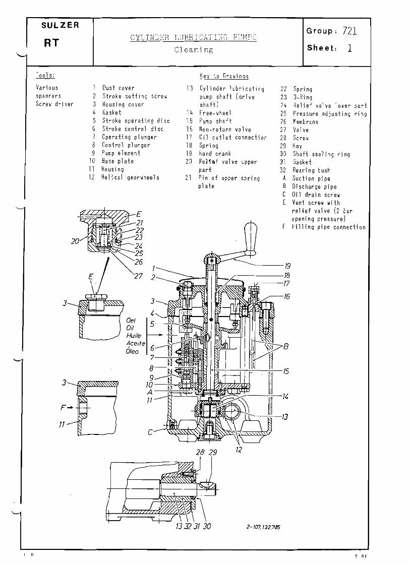
1
SULZER Group: 721
CYLINDER LUBRICATING PUM?5RT
Sheet:Cleaning
Tools: Key to Drawings
Various 1 Dust cover 13 Cylinder lubricating 22 Spring spanners 2 Stroke setti ng screw pump shaft (drive 23 ORing Screw driver 3 Housing cover sha ft) 24 Relief valve lower part
4 Gasket 14 Freewheel 25 Pressure adjusting r ing 5 Stroke operating disc 15 Pump shaft 25 Membrane 5 Stroke control disc 15 Nonreturn valve 27 Va 1ve 7 Operating plunger 17 Oil outlet connecti on 28 Screw 8 Control pl unger 18 Spring 29 Key 9 Pump element 19 Hand crank 30 Shaft sealing ring
10 Base pl ate 20 Rellllf valve upper 31 Gasket 11 Housing part 32 Beari ng bush 12 Helical gearwheels 21 Pi n of upper spring A Suction pipe
plate B Discharge pipe C Oil drain screw E Vent screw with
relief valve (2 bar opening pressure)
F Filling pipe connection
1228 29
2107. 132.785
I 0 ? QI,

721/1a RT
Procedure for Cleaning
To clean (flush) acyl inder 1ubricating pump, shut off the feed pipe to the housing and unscrew oil drain screw IC' and vent screw IE'.
Fill clean paraffin or flushing oil into the hole for vent screw IE' until the oil sludge is f1 ushed out.
Before refitting oil drain Screw 'e', sl ight1y open the shutoff cock of the feed pipe so that the remaining paraffin or flushing oil can be flushed out.
To refill the housing with fresh oil, first completely screw in vent screw IE' and then unscrew it by 12 turns while fully opening the shutoff cock. After venting, retighten vent screw 'EI.
Before putting the cylinder lubricating pump back into service, turn pump shaft 15 with the hand crank 19 until the visual flow control situated on top of the cylinder lubricating pump shows that all operating p1 ungers 7 are discharging oil.
Note: When installing a spare cylinder lubricating pump during replacement we recommend that it be cleaned internally as described above before putting it into service. The individual pump ele-ments 9 which are connected to a lubricating point should also be adjusted to the data given in the timing records since the operating plungers are set by the manufacturers to full stroke. The effective stroke, and therefore the oil delivered per pump element, can be adjusted with the stroke setting screw 2 (with click stop) as follows:
by turniQg clockwise reduced oil delivery by turning anticlockwise = increased oil delivery.
L.B. 2.84

· "~~ t~.~ ,'" ..;,:.",', ":".
INSTRUCTION FOR MOUNTING AND DISMOUNTING OF THE DRIVING SHAFT
ON THE REXROTHVALVE' OF THE CYLINDER LUBRICATION. I
1. Dismounting.
Should:casing 5, after loosening of fastening screws 4, not.'
be removable without applying force, then the c a ~ i n g is of
the newer design execution which is equipped with a coupling
without clearance between driVing shaft and throttling bush.
(Valve manufactured after 1.7.83).
On these new valves gear wheel 3 bas to be removed. The
braclnQ of the coupling can be released by turning beck
threaded pins 9.
Attention: When lifting driving shaft 6.the synthetic
balls 8 may fallout.
It is to be recommended to mark the correct fitted position
for remounting, after haVing separated the coupling. -2. Mounting.
Should the correct fitted position of driving shaft to
throttling bush not have been marked, then the valve must
be dismantled from the valve plate, so that the through flow
from 'A' to ' ~ . can be verified by compressed air.
-
Symbolisdte Dlnlellung SYNSOLIC aAtJRAN •
r····_·, A i ~ is
i{ ,_J i'& - * I
iI !p II i t I _.:"
r.....L
~
NlflLE "IIDrAJDI
.......... ,.... -- r--;~;:~;-""'''''''I-:~=~;;-;:;::;~;;;:--''''-'''''1!Dr;tIW;; ..L:::tAiI!i;';=:JiaQg.s~·~st-ilRT 58 + 84 MOUNTING INSTRUCTION
RL 56 + 90 FLOW CONTROL VALVE (REXROTH) I--.;.;;....y".;..;;...+.......---I
I......
,PIlJO.8U'.W' .. ~
E 4- 107.Q9,.?Z7 ..... 1 ., 3

< :. r-";:,, :"::".:'.:C"'; '·· •. 1.
',t',
In zero stop (driving shaft rotated in counter clockwise direc
tion) no tbrough flow must occur from 'A' to 'B'.
When rotating the driving sbaft in clockwise direction, the
valve must open after lSo and the tbrough flow in the end stop
reach its maximum after 3000
turning angle.
- After correctly replacing the driving shaft, insert synthetic
bals e and threaded pins 9 and tighten them lightly, so that
the c l e a r a ~ c e in the hexagonal connection is cancelled.
- The driving casing 5 must be aligned in such a way, that after
t i g b t e ~ i n g the fastening screws, the driving shaft can be tur
ned easily•
.-
............. .-. fI=iR;m~5~8~+~84;;:I:Ir;;;;;~::;~::;~::=I:==llull~.,~;.;ar;:~ ....~,.,~. ;;.~=E.IO~~~.9f"d
~. MOUNTING INSTRUCTION
BL 56 + 90 FLOW CONTROL VALVE (REXROTH) WI.....
IiULZ&R' E 4.10'7.093.727 .... 2 .. 3

( ) ( \ ( ;~ ( (
) )
leIo_ 4107. 09J.727
A To hydraulic motor
....
A ~
--
10 ·I~
8 9
-_._..... 10/-
11)<1 1 1)1(1 I IWl 1 I'J<I 1 I
-
6
>
7
"I ~ I -'
<"
Reflux
Inlet
~ . 1
1
9> {g' I.
8 A T ........ o
o......... _ - . _ ~ .._ ....
~ . . . - - - . . . . - -.....__ ::=., .. z.- !lIIIIIl ...=. - ..Iw.IcJot.
Item 8 & 9 only on valves manufactured after 1.7.83
"T58 -84 IMOUNTIIICl INSTRUCTION FLOW CONTROL VALVE
RL 56 90 (REXROTH)
SULZER IE 14107.093.727
Ge.
0...
,,_.
3/1 _.t'''' """. ~

1
SULZER JRIVING SHAFT TO THE FLOW CONTROL VALVE Group: 722 OF THE CYLINDER LUBRICATIONRT Sheet: Dismantling and Assembling
Key to III ustrati on
1 Screll 6 Driving shaft
2 Locking plate 7 Key 2a End pl ate 8 Syntheti cs ball 3 Spur gear 9 Threaded pin 4 Screll 10 Floll Control Valve 5 Casing 11 Floll control valve shaft
Should the troublefree functioning of the floll control valve (REXROTH) not be assured for any reason, it has to be exchanged against a nell one. The removal of the valve off its driving shaft and the fitting of the nell one requires particular care, it is therefore recommended to folloll carefully the instructions given herebeloll. The company (REXROTH) lIill take care of reconditioning the defective valve upon request.
Di smantl i ng
Loosen the screll 4 and gently try to lift the casing 5 off the valve 10. If this is not easily achieved the floll control valve is of the neller type IIhich is equipped lIith clearance-free coupling betlleen driving shaft and throttling bush (The valve are manufactured after 1.7.83)
- On the nell valves, the spur gear 3 has to be removed. The fastening of the coupling can be loosened by turning back the threaded pin 9.
Attention~ When removing the driving shaft the small synthetics ball 8 may fallout.
- It is recommended to mark the correct fitting position for the reassembly after removing the coupling.
Assembl ing
- In case the correct fitting position of the driving shaft to the throttling bush has not been marked, the valve must be removed off the valve plate to check the through floll from .A to B lIith compressed ai r.
Durchflusskennlinie
FLOW CHARACTERISTIC(I/trin,)
6 0 - J - r - r - - ~ - ~ - ~ - " T " " " - " " " - - - " - - - / - - - - ; ; I I ' I
SO-I-+-+--+--+--+---+---+------+-:.."e-----1 /'"
S>mbolische DorsteIlung l:I /'..2 ~ ~ -1-+-+--+---f---+----+--t-7fI'<'---+--------I
SYMBOLIC DIAGRAM,0_' ._', ! ~ 3O-I-i-+_+-_I---+_~/~+-V __--+__----I
A • 1. is ~ /! A '! 2D-1-+-+--+---f---'7'G----+--t----+--------I• r- Y II, r-----.....--' //
L , r-~ . 10 -I-hl---::II-L----lf----lf----l----l----i------I
i lOt IL. --.-...:.:::-_- J [//
O-Q--!'I,~. --+,----;.--f-,--+.----+,----.;-,------+,....L...!l o 300 60· 90· 120· 1S00 180· 2400 3000
DrMwiflhi 4t02215.218ANGLE OF R(]fATiON

722/la RT
_ In the zero stop position (driving shaft turned in anticlockvise direction) tay be no flov frol A to B0
Whe~ turning the driving shaft in clockwise direction the valve should begin to open after 15 and the
flow lust reach its laxilul at the end stop after a turn of 300°.
_ After correctly fitting the driving shaft 6, insert the siall synthetics ball 8 and the threaded pin 9~
and tighten lightly so that no clearance relains in the hexagon connection.
_ Adjust the drive gear casing 5 in such a way that after tightening the fastening screvs 4 the driving
shaft turns easily.
I
zum Hydraulikmotor TO HYDRAULIK MOTOR
3 -107. 215.211
Pos.8 und 9 nur bei
Venti/en ab 1. 7. 1983
ITEMS 8 AND 9 ONLY ON
5
~ ~II
.",.
5
+ Eintritt
INLET
o 0 Ruck/auft - - - 1 ~ RETURN
8 T
1 VALVES MANUFACTURED AFTER 1.7. 1983
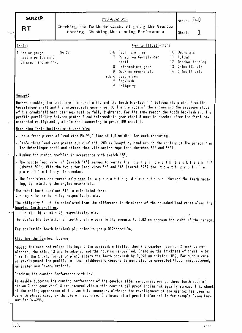
SULZER P T Q · - G E A R 8 0 ) ~ Group: 740 Checking the Tooth Backlash, Aligning the Gearbox
RT Housing, Checking the running Performance Sheet: 1
Tools: Key to III ustrati ons
1 Feeler gauge 94122 06 Tooth profiles 10 Bedplate Lead wire 1.5 mm 0 7 Pinion on Geisslinger 11 Col um n Oilproof indian ink. shaft 12 Gearbox housing
8 Intermedi ate gear 13 Shims (X.Jxis 9 Gear on crankshaft 14 Shims (Yaxis
a,b,c Lead wires f Backlash f Obliquity
Remark!
Before checking the tooth profile parallelity and the tooth backlash 'f' between the pinion 7 on the Geisslinger shaft and the intermediate gear wheel 8, the tie rods of the engine and the pressure studs of the crankshaft main bearings must be fully tightened. For the same reason the tooth backlash and the profile parallelity between pinion 7 and intermediate gear wheel 8 must be checked after the first re
~ commended re-tightening of tie rods according to group 190 sheet 1.
Measuring Tooth Backlash with lead Wire
- Use a fresh pieces of lead wire Pb 99.9 fine of 1.5 mm dia. for each measuring.
- Pla~e three lead wire pieces a,b,c,of abt. 200 mm le~gth by hand around the contour of the pinion 7 on the Geisslinger shaft and attach them with scotch tape (see sketches lA' and 'BI).
- Number the pinion profiles in accordance with sketch 'BI.
- The middle lead wire 'c' (sketch 'A') serves to verify the tot a 1 too t h b a c k 1 ash If' (sketch 'C'). With the two outer lead wires 'a' and 'b' (sketch 'A') the too t h pro f i 1 e par all eli t y is checked.
- The lead wires are turned only once in 0 per a tin g d ire c t ion through the teeth meshing, by rotationg the engine crankshaft.
The total tooth backl ash' f' is cal cul ated from: ~.= fcO + ftl or fCl + ft2 respectivel y, etc.
The obliquity' fl is calculated from the difference in thickness of the squashed lead wires along the bearing tooth profiles:
"--' f '" al - bl or a3 - b3 respectively, etc.
The admissible deviation of tooth profile parallelity amounts to 0.03 mm accross the width of the pinion.
For admissible tooth backlash pl. refer to group 012/sheet 9a.
Aligning the Gearbox Housing
Should the measured values lie beyond the admissible limits, then the gearbox housing 12 must be realigned, the shims 13 and 14 adapted and the housing re-dowlled. Changing the thickness of shims 14 by 1 mm in the X-axis (minus or plus) alters the tooth backlash by 0,698 mm (sketch 10'). For such a case of re-alignment the posItion of the neighbouring components must also be corrected.(Couplings,Co.Speed,
generator and Power-Turbinel.
Checking the running Performance with Ink.
To enable judgeing the running performance of the gearbox after re-commissioning, three teeth each of pinion 7 and gear wheel 8 are smeared with a thin coat of oil proof indian ink equally spread. This check of the mating appearance of the teeth is necessary although the re-alignment of the gearbox has been made with utmost care, by the use of lead wire. One brand of oilproof indian ink is for example Oykem Layout Red Ox -296.
L.B. lOQC::

740/10 RT
Gezeichnet fur Standart - Ausfuhrung
r n A W N m R S r n N ~ R T a ~ U m N
® Nicht tragende
NON DRIVING
o z= 15mm @
7
12
13
.______7
Flanken
FLANKS
Aanken
FLANKS
(
\",--",
Ritzel
PINION
Tragende
DRIVING
4 -107. 240. 111
1986L. B.

SULZER PTO GEARBOX Group: 740 Removing and Fitting the Gearbox Components
RT as well as of the intermediate Gear Wheel Sheet: 2
Too 1s: Key to Illustration
1 Feeler gauge 94122 1 Drilling co1um n 13 Housing lower part 25a Screw 1 Depth gauge 94124 2 Cover 14 Cover 26 Sl i ngerr i ng 1 Connecting branch 94425 3 Cover 15 Cover 27 Intermediate 1 HP hose 94935 4,4a Beari ng 16 Coupling flange gear 1 AirHydraulic HP pump 94942 5 Gear whe&l 17 Fluid coupling 28 Intermediate 1 Wi thdrawal device for 6 Geislinger coupling 18 Upper cladding half gear bearings
taper dowel pi ns 7 Geislinger shaft (i n 18a Lower cladding hi! lf 29 Screws 2 Ring screws termediate shaft) 19 Screws 30 End cover
7a Pinion 20 Fixing plate 31 Locating dowels 8 Vent screw 21 Screws 32 Locking strap 9 Waisted bolts 22 Intermediate ring I a I Connecti ng
10 Pi ni on shaft 23 Bearing thread I bI11 Coupli ng ri ng (2piece) 24 Bearing Connecti ng
12 Ho usi r]g upper part 25 Disc thread , f' Mounting surfa-
~
ce 'x I Pressingon mea
Removing and Fitting the Geis1inger Shaft sure
For.'removi ng the Geis1inger shaft 7 (Sketch 'A' and 1B') proceed as follows:
Disconnect and remove all connecting piping for oil and, possibly air. Loosen all screws to driving column 1 and remove the cover. Loosen all the screwed fastenings between housing upper part 12 and housing lower part 13. The hous-
ing lower part remains fastened to the column of the main engine. Loosen the screwed fastenings to covers 2 and 3 as well as 14 and 15. Lift housing upper part 12 with lifting tackle up and take care that the upper part does not jam in
the bearing guides. The Geis1inger shaft together with the two bearings 4 and 4a is now lifted out of the housing lower
part with suitable lifting tackle. Take care that the two bearings slide out of their guides without jamming and that the gear teeth are not being damaged.
Fitting the Geis1inger shaft is carried out analogous to the removing but in reverse sequence.
Removing and Fitting the Pinion on the Geislinger Shaft as well as the Gear Wheel on the Geislinger Coupling (Sketches 'AI and 'BI)
After removing the Geis1inger shaft and the removal of the bearing 4 the pinion 7a can be withdrawn with the aid of a hydraulic jack. For this,mount the connecting branch 94425 on the fr~nt face of the Geislinger shaft at connection 'a'. Raise the pressure slowly with HP pump 94942 until the pinion can be pushed off the Geis1inger shaft. Attention! The pinion may suddenly slide off the shaft, it must therefore be secured against a wooden block. For the removal of the gear wheel 5 on the Geis1inger coupling 6 the Geis1inger shaft 7 is placed ver-tically on supporting blocks, the Geislinger coupling uppermost, the waisted bolts 9 having first been slightly loosened. Remove the waisted bolts 9. Drive two ring screws into the threads of the vent screws 8 . The Geislinger shaft/coupling assembly can now be pulled upwards out of the gear wheel. For assembling proceed analogous to dismantling but in reverse sequence, thereby pay attention to the following:
Smear the thread of the waisted bolts 9 for screw fastening the gear wheel 5 to the Geislinger coupl-ing 6 lightly with Mo1ycote paste G. Tighten all the waisted bolts now diagonally across. (For tigh-tening torque please refer to group 013/sheet 2).
Prior to fitting the pinion 7a onto the Getslinger shaft 7 heat the same to 17D1800
C. Before fitting the pinion make sure that all contact surfaces on the shaft and inside the pinion bore
are clean and free from grease.
L. B. '1 07

740/2a RT
_ After fitting the plnlon check immediately with the feeler gauge that it rests snug without clearance against the seating surface If I (sketch 'BI).
Removing and Fitting the Pinion Shaft
For removing the pinion shaft 10 proceed as follows:
Disconnect and remove all connecting piping for oil and, possibly air.
Loosen all screws to driving column 1 and remove the cover.
Loosen all the screwed fastenings between housing upper part 12 and housing lower part 13. (Sketch IAI
Housing lower part remains screw fastened to the column of the main engine.
Loosen the screwed fastenings to covers 2 and 3 as well as to 14 and 15 (Sketch IB').
Lift casing upper part 12 off with suitable lifting tackle, paying attention that the upper part 13 does not jam in the bearing guides.
Should a clutch be fitted immediately near the gearbox )e.g. Lohmann + Stolterfoth clutch) then the cou-pli~g studs to the coupling flange 16 must be removed and the 2piece coupling ring 11 taken off. To prevent damage to the clutch follow also instructions of clutch manufacturers.
Should a fluid coupling 17 be fitted immediately near the gearbox (sketch 'C' e.g.Voith coupling) pro~
ceed as follows:
To prevent damage to the fluid coupling follow the instructions of its manufacturers.
Disconnect and remove all necessary. connecting piping for oil and, possibly air.
Loosen all screws to driving column 1 and remove the cover.
Loosen all the screwed fastenings:between housing upper part 12 and housing lower part 13 (Sketch 'A').
The housing lower part 13 remains screwed to the column of the main engine.
Loosen the screwed fastenings to covers 2 and 3 as well as 15. (sketch '8').
Loosen the screwed fastenings to the upper cladding half 18 of the fluid coupling 17 and remove the cladding half. (Sketch 'c').
Remove the oil drain pipe to the lower cladding half 18a of the fluid coupling 17.
Suspend the lower cladding half 18a by suitable means.
Disconnect screwed connections to the lower cladding half 18a, then turr the cladding half on the cen-tring diameter upwards and lift it off.
Loosen the fastenings to cover 14 and remove.
The housing .upper part 12 can now be lifted off with suitable lifting tackle. lake care that the hou-sing upper part does nut jam in the bearing guides.
Remove screws 19 and push fixing plate 20 back (sketch '0').
Remove screws 21 and push back the intermediate ring 22.
.The plhion shaft 10 can now be lifted out of the housing lower part 13 by suitable lifting tackle. Should an air connection be built into the pinion shaft for the clutch actuation, dismantle same befo-re removing the pinion shaft.
Refitting the pinion shaft 10 is done analogous to its removal but in reverse s e ~ u e n c e . thereby be sure to follow the instructions of the coupling or clutch manufacturers. Should it become necessary to inspect bearing 23 (sketch 'BI and 'C') on the side of the fluid coupling 17 or to replace the same, then the fluid coupling 17 must first be dismantled (see group 750/sheet 1 and instructions of the coupling manufacturers). If the bearing 24 on the side of a clutch have to be removed proceed as follows:
Drive connecting branch tool No. 94425 into the threaded bore 'b' of the coupling flange 16 (sketch 'E'
Connect HP hose 94935 and hydro HP pump 94942 to the connecting branch.
L. B. 2.87

740/2b RT
Fasten disc 25 by screw 25a firmly to the front face of the pinion shaft.
~ raise the pressure for withdrawing the coupling flange, until the coupling flange is freely mo-vable and, after loosening the screw 25a slides offf the pinion shaft. (Maximum pressure 1200 bar)
Exceptionally the coupling flange can also be withdrawn by heating it.
Bearing 24 can now be removed.
For assembling proceed as follows:
Push bearing 24 as well as slinger ring 26 onto the pinion shaft 10.
Keep all contact surfaces in coupling flange 16 and on pinion shaft 10 clean and free of oil.
Push coupling flange in cold condftign onto the pinion shaft (sketch IF').
Measure the distance 'X' frOM the front face of the coupling flange to the front face of the plnl0n shaft with depth gauge 94124. (Shrinkon distance). This distance should measure between 10.4 and 12.5 mm. (Any corrections may only be carried out in the flange bore).
Heat coupling flange to 200_2200C.
ijse disc 25 and screw 25a to press the coupling flange on until it rests against the shoulder of the slinger ring 26.
o Leave disc 25 with screw 25a fitted until the coupling flange has cooled to abt. 45 C.
Check with feeler gauge whether the coupling flange rests snug without clearance against the shoulder of the slinger ring 26 (sketch 'B~).
Reloving and Fitting the cOlplete PTO Gearbox
Should the complete PTO gearbox have to be taken off, then the previously described possible clutch con- nections to the pinion shaft 10 (sketch 'A') as well as all piping connections to the PTO gearbox must first be removed. Loosen screw fastenings to driving column 1 and remove the cover. loosen the screwed fastenings between the PTO gearbox and the main engine. The PTO gearbox can then be lifted away with the crane.
After refitting the PTa gearbox to the main engine the tooth backlash between the pinion 7a and the in- termediate gear wheel 27 must be checked (pl.refer to group 740fsheet 1). The couplings/clutches neig- bouring the pinion shaft 10 must be also checked in accordance with lanufacturers instructions for cor~ . red ali gnllent.
Removing and Fitting the Intermediate Gear Wheel 27 to the PTa Gearbox
For the removal of the intermediate gear wheel 27 to the PTa gear wheel proceed as follows:
Remove PTa gearbox complete from the main engine as described above
Rotate the engine crankshaft so, that the screws 29 fastening the intermediate shaft bearings 28 are _ easily accessible from the crankcase. (Sketch 'B').
Secure turning gear against accidental starts.
Remove the oil supply pipe to the bearing lubrication of the intermediate gear wheel.
Hount a lifting tackle 'c' in the gear column (sketch 'G').A further steel rope 'd' to be fastened to the crane outside the engine.
Stretch steel rope 'c' taut, loosen screws 29 to the two intermediate bearings 28 and remove together with the two end covers 30.
Remove two each locating sowels 31 in both intermediate gear wheel bearings 28 with the aid of the with drawing tool.
Use lifting tackle IC' together with the crane rope 'd' (sketch 'GI) to lift the intermediate gear wheel together with its two bearings out of the engine.
After the removal of the intermediate gear wheel the two bearings can be pulled off, after dislocating the locking straps 32.
l. B.

740/2c RT
~
For fitting the intermediate gear wheel proceed analogous to its removal but in reverse sequence. The two bearings to the intermediate gear wheel must without fail be refitted in the original position, as they were exactly dowelled. The intermediate gear wheel must be fitted in such a way that the marking ftORIVING ENOft faces towards the driving end. (Additional information are given in group 410). After the fitting the·tooth backlash must for safeties sake be checked (pl.refer to the clearance table group 012 sheet 9a).
Remark: Metallic sealing surfaces on the PTO housing must be sealed with a thin spreading sealing compound.
L. B. ?P..7

740/2d RT
31 5 64089
2 30
11
16 26 15
~-$-
28 24
32
10
32 , ..: , ", ••,,
I
I ,:".I I,
",," I'"I: -$-,
'I "
--_.:::Y , ,
, ...
'30 II
~ +II
" "
4 10Z 240,095
® 29
L. B. 1986
13
2
23

RT740/2e
©
10 18
@ 22
21
20 19
17
4107. 240.094
L.B. 1986

740/2f RT
®
®
'd'
'x
4 107. 240. 100
L. B. 1986

SULZER GEISSLINGER COUPLINGS Group: 740
External Inspection for Oil LeaksRT and constant Venting Sheet: 3
Key to III ustrati ons
1 Orings (for shaft sealing) 2 Orings (for side plates) 3 Nozzles for constant venting 4 Vent screws
In specti on s
External Inspection
_ It is recommended to inspect the coupling externally for oil leaks in intervals of 1000 2000 operat-ing hours. Leaking orings are easily diagnosed when the coupling is subjected to oil under pressure.
_ Constant venting through the nozzles 3 must be guaranteed. The openings of these n~zzles must be clea-ned at each inspection. Their free passages may not be enlarged under any circumst~nce!
Complete Inspection (Removal, Dismantling)
'" Every 18'000 20'000 operating hours a complete inspection should be carried out, whereby part subject to wear are to be replaced. For overhauls the instructions of the coupling manufacturers must be follo-wed conscienciously.
Extra~Scheduled Inspections
Should any deffects be noticed on the cranshaft bearings or the gearbox bearings due to the water con-tents in the lubricating oil, then it is essential at the next opportunity also to inspect the coupling for corrosion damage or wear at the spring ends respectively.
Note: Design and position for the constant venting through the nozzles 3 (see illustration) , can differ depending of the coupling design.
L. B. 1.89
740/3a RT
Maintenance on and servicing of the Geisslinger couplings is carried out by:
Dr. Ing Geisslinger &Co.
Atteliers et Chantiers de Bretagne
Al sthomAtl antique
Oy Wartsil a A~
Ishikawajima Harima Heavy Insustries Co. Ltd.
Niigata Engineering Co. Ltd.
Nippon Kokan Kabushiki Kaisha
Blohm & Voss AG
A.P.E. Crossley Ltd.
Van Stigt B.B.
Eaton Corporation, Insustrial Drives Operatio~s
Marine &Diesel Service Pty. Ltd.
A5023 Salzburg/Austria
F44040 Nantes/Cedex FRANCE
Departement Moteurs F93203 St. Denis FRANCE
Etablissement Mecanigue F44550 Montoir de Bretagne
SF20810 Turku 81 FINLAND
Tokyo 100, JAPAN
Tikyo 100, JAPAN
Yokohama, JAPAN
02000 Hamburg 1 GERMANY WEST
GBManchester Mll 20P GREAT BRITAIN
Avelingen West 30 NL4204 MS Gorinchem NETHERLANDS
Cleveland, Ohio 44144, USA
Artarmon, N.S.W. Australia 2064
L. B. 1986

740/3b RT
Kupplung im Massenausgleich Kupplung im P. T.O ~Getriebe
Antrieb
COUPLING TO BALANCING COUPLING IN P. rD. - DRIVE
GEAR
L. B.
2 2 3 1 3
4- 10Z 240. 101
1986

EfficiencyBooster SULZER Group: 750Removing and Fitting the Hydraulic Coupling
as well as the Flexible Pad Coupling RT Checking the Oil Level of the Hydr. Coupling and Sheet: 1\. . the Alignment of the Power Turbine 1............;;;...........-------1
Tools: Key to Illustrations:
1 Inside micrometer 94101 1 Hydr. Coupling 11 External ring to flex. 1Feeler gauge 94122 2 Pinion shaft to PTO pad coupling
1Mounting device for hydr. coupling
94751 3 Hub to flex. pad coupling
12a 12b } 12 Power turbine
Exhaust gas turbine Planetary gearbox
1Withdrawing device for 94752 4 Output shaft to 13 Screws hydro coupling power turbine 14 Fixing plate
1Allen screw 94752a 5 Screw 15 Horizontal set screw 1Mounting device for 94753 6 Disc 15a Lock nut (self locking)
flexible pad coupling 7 Intermediate ring 16 Vertical set screw 1Withdrawing device for 94754 8 Screw 17 Waisted screw
flexible pad coupling 9 Disc 18 Screw 1Allen screw 94754a 10 Rubber pads 19 Lower casing half 1 Lever dial gauge with 20 Rib
magnetic holder
To remove the hydro coupling 1 (Voith coupling) from the pinion shaft 2, resp. the hub to flexible pad coupling 3 from the output shaft 4 to power turbine, the hydro coupling must first be separated from the flex. pad coupling as described in group 740/sheet 2. Further the pinion shaft 2 has to be removed as described in group 740/sheet 2 resp. the power turbine, to provide the necessary space for the removal of the couplings. For maintenance work on the above mentioned couplings the instructions of the coupling manufacturer must be followed without fail.
Removing the Hydr. Coupling
Loosen screw 5 (illustr. "A") and remove it together with 2piece locking plate and the disc 6.
To withdraw the hydr. coupling mount the intermediate ring 7.
Drive allen screw 94752a into the thread on the front face of the pinion shaft.
Mount withdrawing device 94752 onto the hydro coupling as per illustr. 'B'. Smear the sliding portions and the thread of the withdrawing device with Molycote paste to prevent seizures.
Draw the hydro coupling off the pinion shaft with the withdrawing device.
Unscrew withdrawing device and the allen screw 94752a.
Fitting the Hydr. Coupling
Before fitting the hydr. coupling clean its hub bore as well as the shaft portion on the pinion shaft carefully and smear them lightly with Molycote paste.
Push hydr. coupling as far as possible onto the pinion shaft.
Screw mounting device 94751 with stuckon disc 6 into the thread at the face of the pinion shaft (illustr. 'C').
Press hydro coupling on with mounting device until it rests flush against the shaft shoulder. (Check with feeler gauge).
Remove mounting device.
Fit screw 5 with 2piece locking plate and disc 6 and tighten the screw.
L.B. 12.89
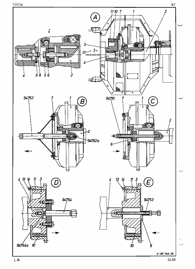
750/1a RT
9 ~ 7 5 2
I
98 56
7
2
1
14752a
1110 7 1 2
@
109475~a 10
4-107. 240. 710
L.B. 12.89

I .)V, 1.0 RT
Removal of Hub to Flexible Pad Coupling Whenever the flex. pad coupling is removed, rubber pads 10 have to be checked.
Loosen screw 8 (illustr. 'A') and remove it together with the 2piece locking plate and disc 9.
Drive allen screw 94754a into threaded hole on the face of the output shaft of the power turbine.
Mount withdrawing device 94754 to the hub 3 of flexible pad coupling as per illustr. 'D'. To prevent seizures of the sliding parts and the thread on the withdrawing device, smear these with Molycote paste.
Using the withdrawing device pull the hub of the flex. pad coupling off the output shaft to power turbine.
Dismount the withdrawing device together with allen screw 94754a.
Fitting the Hub to Flexible Pad Coupling
Before the fitting clean the bore in the hub to flex. pad coupling, as well as the output shaft to power turbine carefully, then smear bore and shaft lightly with Molycote paste.
Push the hub to flex. pad coupling as far as possible onto the output shaft to power turbine.
Screw mounting device 94753 with stuckon disc 9 as per illustr. 'E' into the thread at the face of the output shaft to power turbine.
With the mounting device, press the hub to flex. pad coupling on until it rests flush against the shaft shoul-der (Check with feeler gauge).
Dismount the mounting device.
Fit screw 8 together with the 2piece locking plate and disc 9 and tighten the screw firmly.
Checking the Rubber Pads (see illustr. 'F')
The rubber pads 10 have to be checked periodically according to the maintenance schedule visual on their condition and wear as well as cracks. Rubber pads usually wear in steps from the hub to the flex. pad coupling in output direction of rotation of the power turbine. If the pads are worn by more than 3 mm, they must be replaced completely. For the checking and possible replacement of rubber pads the coupling has not to be removed. This entails loosening and removing of screws 13 to fixing plate 14. Now the rubber pads 10 of the power turbine side can be pulled off the grooves and checked. Should this checking not reveal unmistakable wear pattern then all rubber pads have to be checked. For this, loosen the screwed fastening to the external ring of flex. pad coupling 11 and remove it. Then push the external ring in direction of power turbine 12, till the remaining rubber pads are exposed. Take good care, when pushing the external ring back, that the rubber pads (3part) do not fall into lower casing half 19 (illustr. 'K') of the hydraulic coupling. Consider existing markings on intermediate ring 7, external ring 11 and hub 3 at assembling.
Coupling Type Voith 7S0TC contains 42 rubber pads. Coupling Type Voith 866TC contains 60 rubber pads.
3
® 13
14
4 107. 240.382
L.B. 12.89

750llc RT
Oil Level Checking of the Hydraulic Coupling
The oil level of the hydraulic coupling has to be checked periodically according to the maintenance schedule. If the hydraulic coupling has been dismantled and overhauled and after reassembling the coupling it has to be again filled according to the following specified oil quantity and with the oil quality specified by the coupling manufacturer. The same applies, when the oil after a longer operational period no longer fulfils the specifica-tion (please refer to the maintenance schedule) or after the fusible plugs had melted.
Hydr. coupling type Voith 750 TC Filling quantity 50 It.! Rotating angle 91/3 screws (64,5°) Hydr. coupling type Voith 866 TC Filling quantity 88 It.! Rotating angle 71/S screws (54°)
A checking has to be done of the correct oil filling of the hydraulic coupling as described below. For the checking the ship must float in the water as straight as possible.
1. Unscrew the filling plug marked with an oil funnel tube on the hydraulic coupling (on the side towards the power turbine).
2. Unscrew the topmost fusible plug (on the side towards the PTO gearbox).
3. Rotate hydraulic coupling slowly by hand, until oil just begins to spill out from the bore for the fusible plug.
4. Count the number of screws of the housing binding to the hydraulic coupling starting from the bore for the fusible plug till the vertical line (pI. refer to the illustr. 'G' below). The vertical line has to be drawn from the middle of rib 20 of the power turbine suspension (pI. refer to illustr. 'K') to the flange of the hydro coupling.
Attention:
As first screw has to be counted the one which in the direction of counting lies after the section plane through .the bore of the fusible plug. A screw which lies in the section plane through the bore of the fusible plug must not be counted.
5. The oil level must be corrected and then again checked if it does not correspond with above mentioned values.
6. Fit and tighten filling plug and fusible plug.
@ View from PTO Gearbox
Rotating angle
L.B.
Oil level
Fusible lu
12.89

750/1d RT
Overhaul of the Power Turbine
Overhauls on the planetary gearbox 12b (illustr. 'K') of power turbine 12 must be carried out only by the manufacturer. These overhauls are executed by the exchange system Le. the planetary gearbox due for over-haul and sent in is exchanged by a newly overhauled one from the manufacturer. For this reason the over-
__ hauled planetary gearbox must for mounting again be new aligned to the hydro coupling. The exhaust gas turbine 12a alone, without planetary gearbox 12b can however be overhauled on board ship following instruc-tions by the manufacturer (please refer to maintenance schedule).
Attention:
Before dispatching the planetary gearbox for overhaul to the manufacturer works, the flexible pad coupling
has to be removed as described under "Removal of Hub to Flexible Pad Coupling".
Alignment of the Power Turbine (The alignment values and tolerances of the coupling manufacturer may not be applied).
The alignment of the power turbine has to be done without oil pressure in the PTO Gearbox.
At a new alignment of the power turbine it is recommended to fit the flexible pad coupling without rubber pads. However for a later checking of the alignment the rubber pads can be left in. The alignment of the power turbine proceed as follows:
Place the power turbine on the power turbine support in such a way that distance Xl and X2 (illustr. 'H') between seating surfaces is equal.
For the lst alignment operation (with reference to illustr. 'H') adjust the axial position and the parallelity of the axes between power turbine and hydro coupling with the help of an inside micrometer. This adjust-ment has to be done mainly with horizontal set screws 15 and if necess3ry with vertical set screws 16 (illustr. 'K'). The deviation may not exceed ± O,10mm between the individual measuring points.
The 2nd alignment operation for coaxiality (illustr. 'J') requires the use of a lever dial gauge. Place the magnetic support of the lever dial gauge on external ring 11 of the flexible pad coupling. Set the lever dial gauge at measuring point cr:> or @ with a slight pretension to '0'.
Slowly rotate the hydr. coupling with the flexible pad coupling and note and record the measuring values on four points as shown on illustr. 'J'. Deviations between the measuring points may not exceed the tolerances indicated in the table to illustr. J. Corrections have to be carried out by adjusting horizontal set screws 15 and vertical set screws 16 respec-tively (illustr. 'K'). Horizontal set screws have to be beard against the power turbine only, Le. do not tighten so firmly therefore the housing should not be deformed.
Attention! The power turbine has to be so aligned that it finally stays higher than the hydro coupling by the value (Difference of measuring points <D and @) indicated in the table of illustr. 'J'.
After completing the power turbine alignment, check with a feeler gauge the seating points between vertical set screws 16 and the seating surface of the power turbine. The two supporting surfaces must be parallel to each other and all vertical set screws must be seated without any clearance.
Fit waisted screws 17 (illustr. 'K') and tighten in steps across.
Check position of the horizontal set screws 15 again and lock them with lock nuts 15a.
Recheck the alignment of the power turbine as described above and record the measuring values. For this final record utilize a copy of the enclosed checking sheet (illustr. 'H' and'J').
After completing this last check, fit rubber pads 10 (illustr. 'J') immediately. (please be guided by the section: "Checking the Rubber Pads")
Remarks: For power turbine fastenings which do not feature the vertical and horizontal set screws but realized with packing pieces and locating pins pay attention to the following:
1. The alignment tolerances for the power turbine indicated on illustrations 'H' and'J' respec-tively, must be respected.
2. Power turbines which are new aligned have to be again position drilled and pinned.
Should difficulties arise with the pinning of the power turbine, then the locating pins can be omitted. Instead the four side guides for accommodation of horizontal set screws 15 must be fitted (similar to illustr. 'K'). The two side guides on the engine side have to be weldedon. The two opposite side guides however have to be held in place by two screws 18 each (size M16).The flat bars belonging to them have to be weldedon also and serve as a base.
L.B. 12.89

750/1e RT
1. Alignment operations
Axial position and parallelity of axes
L
866TC
750TC
L
LA
I
III I
LBLD---1.---11------ - ~ = F : I = : _ : : _ : : : ! ! t . L . l
~ ? ? ? ? ? ? ? ? ? ? ~ 89.7256
New adjustment. measured
Type of hydr. coupling Nominal size Measuring point Measuring poInt
L LA I LB I LC I LD LA LB LC LD
750 TC 243 :t1,5 :to,10 r---r-----
866 TC 239 :t1,5 Tolerance one with another
2. Alignment operations
Coaxiallty Lever dial gauge
~ r - - - I I - - - - - - - --
r--------------, New adjustment by: .
Place: .
Date: /Slgnature: .
Ships name: .
Type of eng./Maker: ....•••...............
Total running hours of the engine: .
• of the exhaust gas turbine: .
• of the planetary gearbox: .
• of the rubber pads: .
L.B.
New adjustment, measure
Measuring point Measuring point Type of engine
G) G) G)G) 0 0 0 0 -0,15+0,15
:tO,OS:to ,05 RT 52,58 -0,05+0,05 -0,20+0,20
:to,05 :t0,05RT 62.68,72,76 -0,10+0 10 -0,25+0,25
:to,05:tO,OSRT84, 84M, 84C -0,15+0,15
12.89

t :JUt 11 RT
-t-if+-----------
89.7261
Entrance ports and venting grids of casing for the hydro coupling must be always free.
~
~ = = ~ _ - - - 1 6 - - - - _ = = ~ ~
L.B. 12.89

SULZER
RT
Efficiency Booster
Function Checking and Maintenance of the shutoff Flap and the Corner Valve
Group: 750
Sheet: 2
Too1s:
1 Round bar
Key to Illustrations
1 Pin 13 Reset ring 2 Brace dowel 14 Packing segments 3 Flap 15 (StaufferlGrease cup 4 Shaft 16 Orifice 5 Shaft 17 Pneumatic cylinder 6 End position indicator 18 Coupling 7 Pneumatic cylinder 19 Val ve spindl e 8 Guide bush 20 Val ve body 9 Lever 21 Threaded plug
10 Screll 22 Packing unit 11 Beari ng fl ange 23 Stuffing box flange 12 Flange 24 Nuts
25 Bearing bush 26 Ring
Shutoff Flaps (Sketch 'A') Every 68'000 operating hours should a function check of the shutoff flap be carried out. In case of poor combustion, or inferior fuel respectively should the check occur in shorter intervals e.g. every 3'000 operating hours.
For this check pullout the pin 1 and the brace dovel 2 during an operating stop. The flap 3 as vell as the shaft' and 5 including the end position indicator 6 can nOli be checked for easy movement. At the sa· me tiie check also the pneumatics cylinder 7 for ease of movement. Should the flap jam or be movable by hand only vith difficulty then the shutoff flap unit lust be reloved completely. First clean the flap interior from combustion residue. Should after cleaning the flap still not move easily, "remove parts of sutffing box and check their condition. For this relove the lever 9 from the shaft 4. After loosening and removing the screvs 10 the bearing flange 11 and the flange 12 can be removed together with the guide bush 8. Check also IIhether the re-set ring 13 to the packing segments 14 is not tightened too hard. Utilize this opportunity to replace the old packing segments by new ones, taking care that the jointing gaps of the packings are alternately offset by 180°. .
After re-ass8mbling the shut-off flap re-check it once again for ease of movement•• Should during operation a gas leak occur at the packing segments tighten the re-set ring 13 a little more vith the round bar. When doing this make certain that the easy movement of the flap is not impaired.
Remark: The (Stauffer)gre~se cups 15 must be tightened at regular intervals during operation. To fill the grease cups use IUltra Thera Pastel.
Corner Valve (Sketch 18')
The functional check of the corner valve (sketch lD') should be carried out every 6 - 8'000 op~rating
hours (see also operation manual group 750). In case of poor combustion, or'inferior fuels respectively should this check occur at shorter intervals i.e. every 3'000 operating hours. If one of these checks shovs that the valve jals or does not shut properly any more, then the complete unit must be removed during an operating stop. First clean the valve interior as vel1 as the orifice 16 of combustion residue. If after careful cleaning of valve interior and orifice the valve still moves only vith difficulty then the pneumatics portion of the valve lust be removed. Check the 'pneumatics cylinder 17 separately for easy Movement.
a Q7L. B.

750/2a RT
After having taken off the pneumatic part with coupling 18, remove valve spindle 19 together with valve body 20 and threaded plug 21. Check whether gland flange 23 to packing elements 22 is not tightened too much. Clean bores of bearing bush 25 as well as the spindle shank and smear them with 'Ultra Therm Paste' before fitting. It is recommended also to replace the old packing elements 22 by new ones, taking care to offset the individual packing separating joint by 1800
•
After reassembling the corner valve cheCk it again for ease of movement. In the event of a gas leakage occurring at the packing segment in operation,tighten the stuffing box flange 23 lightly. The tightening is done by alternate equal turning the nut 24 while checking carefully that the easy movement of the valve Is not impaired.
9.87

750/2b RT
14
13
15 11 12
10'-__~ ~ l = = ~ 10
8
5'--I---r7T-/1~ 15
3
4 107. 240. 102
L.B.
1 2 15 7
1986

750/2c RT
®
17 1823 25 19 20 1621
I-I
4 707. 240. 70J
LB 9.87

1-101.198.899
T 8
Ansicht auf freies Ende
VIEW FROM FREE END
;'
,/
6
SULZER BALANCER lst AND 2nd ORDER Group:770 Fitting, Removing, Tensioning of Roller4RT76
Sheet: 1Chain, Fitting, Removing of flexibleEq ui pped wi th Coupling and a Camshaft Section
BaJaJJEBT
Tool s: Key to Illustrations
1 Rivet puller 94704 1 Balancer chest 11 Cover in lower 23 Fixing screws 1 Mounting tool 94705 2 Excenter cl adding 24 Fl exi bl e coupl i ng 2 Locating pin 94707 3 Chain tensioner 12 Spindle 25 Oi 1 catcher 2 Rails 94708 4 Roller chain 13 Upper adjusting nut 26 Co upli ng bolt s 1 Feeler gauge 94122 5 Spray nozzle 14 Spacer ring 27 Coupling on the
Lifting tackle 6 Inspection cover 15 Tension sleeve camshaft 7 Side cover 16 Belleville springs 28 Camshaft section 7a Lower cladding 17 Spacer disc R Eye screw 8 Chain drive sprocket 18 Bearing pin S Supporting surface 9 Balancing weights 19 Lower adjusting nut T Support
o with chain sprockets 20 Toothed segment V Chain lock link
10 Chain sprocket with 21 Locking plate X Chain wear measure balancing weight 22 Stop 1edge
About 500 operating hours after commissioning the engine we recommend checking the correct tension of the roller chain and if necessary to adjust it. Further checks on the correct tension should be made periodically after 3000 operating hours. In the same intervals the chain and the chain sprockets should be inspected. The chains must be checked for cracks, seizure traces, seizedup rollers and pins as well as for elon-gations due to wear. The admissible elongation is 1.5% of the original length i.e. when 5 links have reached a total length of 515 mm the chain must be replaced. Please ~lso refer to the measuring method on Fig. 'C', where on the totally detended chain lengths of 5 links are measured and the effective length is described as X Y. The roller chains for replacement must conform to the SULZER specifica-tion.
10 Q I,
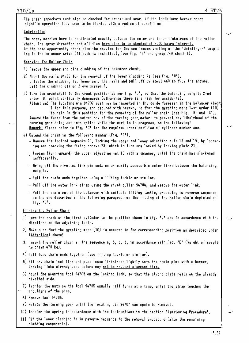
770 la 4 RT76
The chain sprockets must also be checked for cracks and wear. If the teeth have become sharp edged'in operation they have to be blunted with a radius of about 1 mm.
Lubrication
The spray nozzles have to be directed exactly between the outer and inner linkstraps of the roller chain. The spray direction and oil flow have also to be checked at 3000 hours interval. At the same opportunity check also the nozzles for the continuous venting of the lGeislinger' coupl- ing in the balancer drive (if such is installed), (see Fig. 'F' and group 740 sheet 1).
Removing the Roller Chain
1) Remove the upper and side cladding of the balancer chest.
2) Mount the rails 94708 for the removal of the lower cladding 7a (see Fig. 'B'). Unfasten the cladding 7a, lower onto the rails and pull off by about 460 mm from the engine. Lift the cladding off on 2 eye screws R.
3) Turn the crankshaft to the crank position as per Fig. IC', so that the balancing weights 2nd order (9) point vertically downwards (otherwise there is a risk for accidents). Attention! The locating pin 94707 must now be inserted in the guide foreseen in the balancer chest
1 for this purpose, and secured with screws, so that the gyrating mass lst order (10) is held in this position for the removing of the roller chain (see Fig. 'B' and 'C').
Remove the fuses from the switch box of the turning gear. motor, to prevent any likelyhood of the turning gear being set .into motion while the work is in progress, on the following! Remark: Please refer to Fig. 'C' for the required crank position of cylinder number one.
4) Oetend the chain in the following manner (Fig. 10 1).
Remove the toothed segments 20, locking the upper and lower adjusting nuts 13 and 19, by loosen-ing and removing the fixing screws 23, which in turn are locked by locking plate 21.
Loosen (turn upward) the upper adjusting nut 13 with a spanner, until the chain has slackened sufficiently.
Gring off the rivetted link pin ends on an easily accessible outer links between the balancing weights.
Pull the chain ends together using a lifting tackle or similar.
Pull off the outer link strap using the rivet puller 94704, and remove the outer link.
Pull the chain out of the balancer with suitable lifting tackle, proceding in reverse sequence as the one described in the following paragraph on the fitting of the roller chain depicted on Fig. 1['.
Fitting the Roller Chain
1) Turn the crank of the first cylinder to the position shown in Fig. 'C' and in accordance with in-dications on the adjoining table.
2) Make sure that the gyrating mass (10) is secured in the corresponding position as described under (Attention) above!
3) Insert the roller chain in the sequence a, b, c, d, in accordance with Fig. IE' (Weight of comple-te chain 470 kg).
4) Pull lose chain ends together (use lifting tackle or similar).
5) Fit new chain lock link and push loose linkstraps lightly onto the chain pins with a hammer. Locking links already used before may not be reused a second time.
6) Mount the mounting tool 94105 on the locking link, so that the strong plate rests on the already rivetted side.
1) Tighten the nuts on the tool 94105 equally half turns at a time, until the strap touches the shoulders of the pins.
8) Remove tool 94105.
9) Rotate the turning gear until the locating pin 94101 can again be removed.
10) Tension the spring in accordance with the instructions in the section "Tensioning Procedure".
11) Fit the lower cladding 1a in reverse sequence to the removal procedure (also the remaining cladding components).
5.84

770/1b 4RT76
1 ® T
91,708
+
+ +
+
+ +
+ +
+ 91,708 T
7cr 11
11-11 --1 R 7cr
/'
91,708
r /
I ll~
r--, . ::JTf 1\ -+-1 1-+-1 I-+-I I-+-I ·h
~ 1\
--1 91.707
7707.798.893
10RL

, i '-oJ
~~~ ~ ~Q,,~'C "-
~':\~~~ ..~ ~ ,\e /'. ./~ ©./
11 i Teil ungen!P ITCHES ,III Tei lungen!P ITCHES •
Steuerlellenzentrum Steuerlel 1enzentrum
CAMSHAFT CENTER CAMSHAFT CENTER
•
Y/lRN CHAIN
verschl ~~sene Kette = I
~'-- neue 7 ........... I/"l ~ Kette ...... ....
·""'.NEW CHAly'
!
Anslcht auf Antriebseite \ / .~ '~ Anstcht auf fretes Ende ·1.,:;1:17.198.89,VIEW ON DRIVING END VIEW ON FREE END
Kurbelste11ung Zyl. 1
theoretisch 00 n.O.T.P.
Kurbe lste11 ung Zyl.· 1 theoretisch 2700 n. O. T.P.
neue Kette ~ 0,50 n. O.T.P• neue Kette "' 270,50 n. O.1.P.
versch11 ssene Kette '" 3590 n. O.T.P. • Position fur Werkzeug 9~707 (siehe 770!lb) versch1tssene Kette 'V 2690 n. O.T.P.
POSITION FlR TOOL 9~707 (see 770!lb)
POSITION OF CRANK CYL. I POSITION OF CRANK CYL. 1
THElRET ICAL 2700 AFTER TOC
NEW CHAIN i"'" 270,50 AFTER TOC
Y/lRN CHA IN rv 2690 AFTER TOC
THElRET ICAL 0° AFTER TOC
NEW CHA IN ,.., 0,50 AFTER TOC
WlRN CHAIN 359~ AFTER TOC ~
~I I~ ( ( ( (

770/1d 4 RT76
Oberflachen bundig fOR CORRECT TENSIONING fORCE Of THE CHAIN, SURfACE MUST B£ fLUSH
•..
••
3- 107. 198.406
I
.t. ..... L -~-'--------r------'
gezeichnet fur RT 58
DRAWN FOR RT 58
Stellung in fertig verspanntem Zustand POSITION WHEN UPPER NUT IS TIGHT
Stutzflache '5' SUPPORTING SURfACE '5'
Tensioning Procedure
1. Turn engine crankshaft to conform with the indications on Fig. 'C', so that the balancing weights 9 point vertically downwards.
2. Remove the locking elements on the chain tensioner 3 consisting of toothed segment 20 and locking plate 21.
3. Loosen the lower adjusting nut 19 on the tensioner suf-ficiently to permit tensioning of the chain. (about 20 30 mm, see Fig. '0').
4. Tighten the upper adjusting nut 13 on the tensioner until the upper edges of spacer ring 14 and spring cas-ing 15 are flush.
5. Turn crankshaft alternately 'Ahead' and 'Astern'. This will cause the spacer ring 14 to move slightly up and down in the spring casing. The average of the two ex-treme position should be flushness of the parts mentio-ned under 4).
6. Tighten the lower adjusting nut 19 gently by hand to touch the bearing pin 18, lock the nut 19 in this posi-tion with toothed segment 20 and locking plate 21. Checking: the upper edges of spacer ring 14 and spring casi ng 15 must still be fl ush.
7. Tighten the upper adjusting nut fully. First by a turn of about 72 0 till the spacer ring binds on the support-ing surface'S' (the torque rises noticeably), then tighten the nut further by about 10
0; lock the nut 13
with toothed segment 20 and locking plate 21.
8. The tetending of the chain is done in the reverse se-quence.
1984

I
(+)''/
:::::~~-J
~~ I I
.~
4"- Kette
FOR
I"II
fUr Massenausgleich 1.... 2. Ordnung
4"-CHAIN BALANCER ,. ~ 2. ORDER
Ansicht auf Antriebseite 4RT76
VIEW ON DRIVING END~ l...~Y>I~V)elI~· elI~:::: ~I~::J
f8~I· I I. ®
I
I
Gezeichnet fUr Massenausgleich 2. Ordnung
DRAWN FOR BALANCER SECOND ORDER
1107. 198. "08
d
(+j '-----/'
~
~
l'
:0 '"""i "'I
( ( ( ( ,
'0) I

---- -
770/1f 4 RT76
90t.O.5Freies Ende
FREE END
I I I_.1..1.__
VENT FROM
®I ~ ~ - . . . J
C1JO 1:Jl,)c::
ELASTIC :ac
COUPLlNG\ ~ ~ L 5 ~
0
~C
L5~ I
~i .,,1
Ii 26 t ~ 27 28
~l I I
0-107.198.865
Fitting the flexible Coupling or a Camshaft Section
When refitting a flexible coupling or a camshaft and to ensure proper alignment of the chain in the balancer, pay special attention to the dimension 90 ~ ~.5 mm which must exist between the coupling on the camshaft and the end of the end column, when the axial clearance on the camshaft driving gear wheel is equally distributed. If necessary the camshaft section or the coupling on the camshaft have to be shifted axially (Fig. IF').
The dimension 90:!: 0,5 mm applies also to the driving side of the camshaft.
Checking: The crank of cylinder one and the balancing weights must be as indicated in Fig. 'CI.
1984

770/1 4 RT76
Instructions for:
1. Removal of the Flexible Coupling
Please refer to the removal instruction for the roller chain Sheet 770/1a).
Remove the coupling bolts.
Remove the flexible coupling.
2. Removing the last Camshaft Section on the free Engine End
Turn the engine crankshaft so that the crank position of cylinder number 1 corresponds with Fig. 'C', so that the balancing weights are hanging vertically downwards (otherwise risk of accident).
Block the chain sprocket with balancing weight 10 with tool No. 94707 (see removal of the roller chain 770/1a).
Detend the roller chain.
Support the flexible coupling 24. The oil catcher 25 may be used for this purpose, Fig. 'F'.
Remove the coupling bolts 26. Loosen the hydraulically fitted SKF coupling.
Remove the camshaft section.
3. Removing a Central Camshaft Section
Turn the crankshaft to bring the balancer on the free engine end to its base position, see Fig. 'C'. (Otherwise risk of accident).
_ Block the chain sprocket with balancing weight 10 with tool No. 94707 (see instruction for re-moving the roller chain 770/1a).
Loosen the hydraulically fitted SKF shaft couplings.
Remove the camshaft section.
4. Removing the Gear Wheel on the Camshaft
Turn the crankshaft to bring the balancer on the free engine end to its basic position, see Fig. 'c' and block the chain sprocket with balancing weight 10 with tool No. 94707.
Loosen the hydraulically fittted coupling SKF in the direction of the balancer.
Then turn the crankshaft to bring the balancer on the driving end to its basic position, see Fig. 'C', and block the chain sprocket with balancing weight 10 with tool No •. 94707.
Detend the roller chain on the driving end.
_ Support the flexible coupling 24, The oil catcher 25 may be used for this purpose. Fig. 'F'.
Remove the coupling bolts 26. Loosen the hydraulically fitted coupling.
Remove the camshaft section with the gear wheel.
Remark: When fitting a camshaft section proceed in reverse analogous sequence to the removal! Pay particular attention each time, that the locating pin tool.94707 is removed as instructed (see 770/1a), fitting a roller chain)!
1984

SULZER 68
4-6 RT 76 (with Balancer)84
Tools:
Rivet puller Mounting tool Feeler gauge Lifting tackle
7
6
BALANCER 2nd ORDER Group: 770 Fitting, Removing, Tensioning of the Roller Chain, Fitting, Removing the Sheet: 1
Flexible Coupling and a Camshaft Section
Key to ill ustrations
94704 1 Balancer chest 11 Cover in bo Hom 20 Toothed segment 94705 2 Excenter of chest 21 Locking plate 94122 3 Chain tensioner 12 Spindle 22 Pin
4 Roller chai n 13 Upper adj usb ng nut 23 Fixing screws 5 Spray nozzle 14 Spacer ring 24 Flexible coupling 6 Inspection cover 15 Spring casing 25 Oi 1 catcher 7 Side cover 16 Belleville springs 26 Coupling bolts
8 Chain drive sprocket 17 Spacer disc 27 Hydr. fitted coupl-9 Balancing weights 18 Bearing pin ing on camshaft
with chain sprockets 19 Lower adjusting 28 Camshaft section 10 Deflection sprocket nut S Supporting surface
V Chain lock link X Chain wear measure
1
6
3
2
0-107.198.421
5
11
6
9 10
RT76
8
gezeichnet fUr
DRAWN FOR
Ansicht auf Antriebseite 0 VIEW roWARDS DRMNG END A
r-r;;:==::;::i::~~~~~~::::;::;:;:.:--ifl
About 500 ooeratinq hours after commissioninq the engine we recommend checking the correct tension of the roller chain and if necessary to adjust it. Further checks on the correct tension should be made periodically after 1500 hours. In the same intervals the chains and the chain sprockets should be inspected.
The chains must be checked for cracks, seizure traces, seizedup rollers and pins as well as for elon-gations due to wear. The admissible elongation is 1.5% of the original length i.e. when five links have reached a total length of dimension 'X', the cahin must be replaced ('XI, see table on sheet nO/lb) Please also refer to the measuring method on Fig. IB' where, on the totally detended chain the check measure extends over five links and the effective elongation xy is established. The roller chains for
~ replacement must conform to the SULZER specification. The chain sprockets must also be checked for cracks and wear. If the teeth have become sharp edged from wear they have to be blunted with a radius of about lmm.
17 Rk

770/1a 46 RT
Lubrication
The spray nozzles must be directed exaclty to the slot between outer and inner straps of the roller
chains. Spray direction and oil flow are also to be checked in the 1'500 hrs. interval.
At the same time the nozzles for constant venting the Geislinger Coupling in the balancer drive (if equipped with it) have to be inspected (see Fig. 'E' and group 740 sheet 3).
Removing the roller chain
1) Remove cover on the balancer case.
2) Rotate engine crankshaft as per sketches lB' and 'Bl ' resp. so that the balancer weights point ver-
tically downwards (otherwise risk of accident!). Remove electrical fuses from the turning gear switchboard, thus preventing any likelyhood of the gear to be set into motion while removal work is in progress •
.__ ..._- "- _..._..__.__.__. _ .. Remark! The required position of the first cylinder crank varies with the number of engine cylinders
and also with the rotation direction of the engine. For the applicable alternative the corres-ponding indications are taken from the table Fig. lB'.
3) The chain is now slackened in the following manner: (Fig. 'Cl)
Remove toothed segments 20 locking the upper and lower setting nut 13 and 19 by removing the holding screws 23, which in turn are locked by locking plate 21.
Turn upper setting nut 13 with the spanner upwards till sufficient slackening of the chain is attai- '/ ned.
Grind off rivetted link pins on a suitably located outer link between the balancer masses.
Pull chain ends together, (using lifting tackles, hoists etc.)
Using rivet puller 94704 pull of the outer strap and remove the outer link.
Pull chain out of the balancer case with suitable 1ifting tackle, proceding in reverse sequence as described in the following paragraph for the fitting of a roller chain, depicted in Fig. '0'.
Fitting the Roller Chain
Turn the crank of the first cylinder as per sketches 'BI and 'Bli resp. to the position shown in the ta- ble (770/1b).
Insert the roller chain in the seq,uence a,b,c,d, as shown in Fig. 'D'.
Prototypes Modified Execution
Pull lose chain ends together (using hoists or similar).
Insert new locking link, and force loose strap with a hammer lightly onto the chain link pins. Previous- ly utilitzed locking links may not be refitted a second time.
Set fitting tool onto the locking link, so, that the solid plate comes to lie onto the already rivetted side
Tighten nuts on fitting tool 94705 equally in sequence by half a turn till the strap lies against the shoulder of the pin.
Remove tool 94705.
Using steel block as anwil rivet the annealed link pins.
~ow tension the chain as specified in the section 'tensioning procedure'.
6.86L. B.
Enaine tVDe RT58 RTG8 RT7G RT84 Roller chain I Ditch 2'" 3" 3'" 4" Ghain weicht in ka I ka 119 226 322 477
RT58 RTG8 RT7G RT84
202 307 470 642

770/1b 4+6RT
Adj"liog oi,gr" I, B,l,o"r 2od ord'r ~ Drawn for 4, 5 and 6 Cylinder Engines RT76 clockwise rotating
Prototvoes. Modified Executions Enaine tvne RT58 RT68 RT76 RT84 RT58 RT68 RT76 RT84 Roller chain
2t n 3" 4"3t" 3" 3t" 4" 4t"pi tth
I XI Max admissible length over 5 pitches mm 323 1387 1451 1515 611 387 1451 1515 61580
Number of itches ( J*c with chain of prototype RT58 (17tJ* 14t
Number of itches RT68 (16tJ* 14 Number of itchesRT58 (1 5t J* 13 RT76 (15tJ* 13t RT58 (15tJ* 13RT68 (14tJ* 12t RT84 (15tJ* 13t RT68 (14tJ* 12t RT76 (13tJ* llt
RT76 (13tJ* lltRT84 (12 J* 11 RT84 (12 J* 11
1-107.198.863
~ ~ ~ - - Worn out chain ~-i--r---- new chai n
~ /~~
\ / I
.~. \ ( .+--~ crankshaft c e n t e r ~
View onto driving end
4cyl. Engine
Crank pas. cyl."l thea reti ca 11 y a. T.O.C. new chain a.T.O.C. Worn out chain a.T.O.C.
5cyl. Engine
Crank pas. cyl. thea reti call y a.1.O.C. new chain a.1.O.C. worn out chai n a.1.O.C.
6cyl. Engi ne Crank pOSe cyl. thea reti call y a.1.O.C. new chain a.1.O.C. worn out chai n a.1.O.C.
View onto free end
4cyl. Engine
Crank pOSe cyl. theoretically 270
0 a.1.O.C.
new chain ~ 270~5 0
a.1.O.C. worn out chain 269 a.1.O.C.
5cyl. Engine
Crank pOSe cyl. theoreticall y 279
0 a.1.O.C.
new chain .... 279 ~ 5° a.1.O.C. worn out chain ....... 278 a.1.O.C.
6cyl. Engine Crank pas. cyl. theoreti call y 285
0 a. T.O.C.
new chain -285~5° a.1.O.C. worn out chain 284 a. T.D.C.
L.8. 6.86

770/1b 4+6RT
Adjusting Diagram to Balancer 2nd Order
Drawn for 4, 5 and 6cylinder Engines RT76 Anticlockwise rotating
Pro to tVDe s Modified Executions Engine Types RT58 RT68 RT7& RT84 RT58 RT68 RT76 RT84
Roller chain [Ditch
2t" 3" 3t" 4 " 3" 3t" 4" 4t"
I X' Max.admissible length over 5 pitches mm 3231387/451 [515 61t387 1451 1515.6i580
Number of itches ( )*= with chain of prototype RT58 (17t)* 14t
Number of itches RT68 = (16t)* 14 Number of itches
RT58 (15t)* 13 RT76 = (15t)* 13t RT58 (15t)* 13
RT68 (14t)* 12t RT84 = (15t)* 13t RT68 (14t)* 12t
RT76 (13t)* llt RT76 (13t)* llt
RT84 (12)* 11 RT84 (12)* 11
.,, Worn out chain new chain
~/-----~
\ / I
\ ( ~._.~.
Crankshaft c e n t e r ~
View onto driving end View onto free end
4cyl, Engi ne 4cyl. Engine Crank pas, cyl. 1 Crank pas. cyl. theoreticall y a, T,D,C. new chain
a. T,D.C. theoretically a. T,D.C, new chain a.T.D.C.
Worn out chain a, T,D,C. a. T,D.C.worn out chain
5cyl, Engine 5cyl, Engine Crank pas, cyl, 1 Crank pas, cyl. theoretically 351
0 a. T,O,C. a.T,D,C.
new chain 35°650 a, T,D,C. theoretically
a, T,D,C. Worn out ch::lin 352 a. T,O,C,
new chain a, T,D.C.Worn out chain
6cyl, Engine 6cyl. Engine Crank pas. cyl. 1 Crank pOSe cyl. theoretically 345
0 a. T,O,C. a. T,D,C.theo reti call y
50 a. T,D,C,new chain ...... 344 a. T,O.C, new chain6
Worn out chai n 346 a. T,O.C, Worn out chain a. T,D.C.
L. B. 6,86
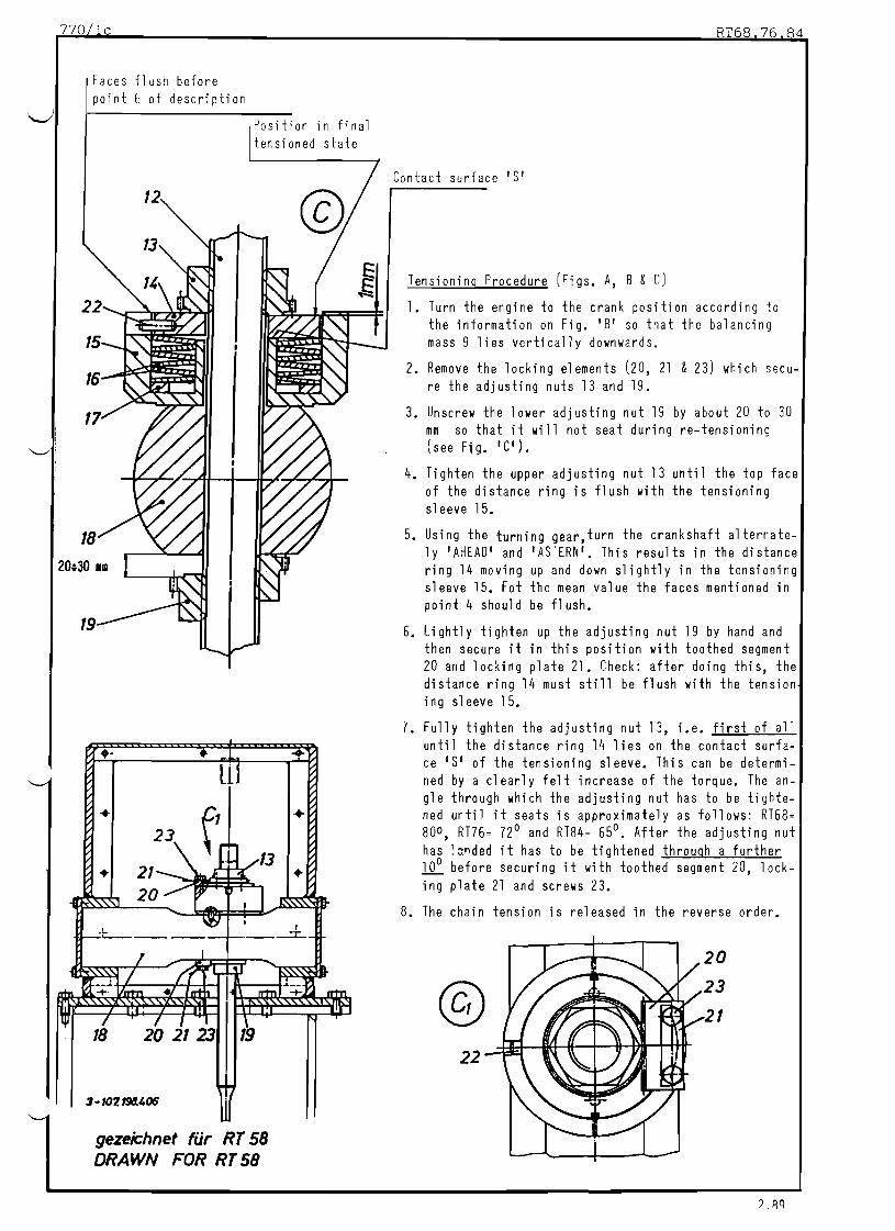
770 lc
Faces flush before point 6 of description
Position in final tensioned state
~ ~
23
.
..
18 20 21 23 19
gezeichnet fUr RT 58
DRAWN FOR RT 58
RT68 76 84
Contact surface'S'
Tensioning Procedure (Figs. A, B & C)
1. Turn the engine to the crank position according to the information on Fig. 'B' so that the balancing mass 9 lies vertically downwards.
2. Remove the locking el ements (20, 21 & 23) which secu-re the adjusting nuts 13 and 19.
3. Unscrew the lower adjusting nut 19 by about 20 to 30 mm so that it will not seat during retensioning (see Fig. 'G').
4. Tighten the upper adjusting nut 13 until the top face of the distance ring is flush with the tensioning sl eeve 15.
5. Using the turning gear,turn the crankshaft alternate-ly 'AHEAD' and 'ASTERN'. This results in the distance ring 14 moving up and down slightly in the tensioning sleeve 15. Fot the mean value the faces mentioned in point 4 should be flush.
6. Lightly tighten up the adjusting nut 19 by hand and then secure it in this position with toothed segment 20 and locking plate 21. Check: after doing this, the distance ring 14 must still be flush with the tension ing sleeve 15.
7. Fully tighten the adjusting nut 13, i.e. first of all until the distance ring 14 lies on the contact surfa-ce '5' of the tensioning sleeve. This can be determi-ned by a clearly felt increase of the torque. The an-gle through which the adjusting nut has to be tighte-ned until it seats is approximately as follows: RT68= 80 0 , RT76= 72 0 and RT84= 65 0
• After the adjusting nut has lorded it has to be tightened through a further ~ before securing it with toothed segment 20, lock-ing plate 21 and screws 23.
8. The chain tension is released in the reverse order.
@ 22

nO/ld
@
Ansicht Quf Antriebseite VIEW ON DRIVING END
@
RT58 = (26)* 21 4nzahl Glieder RT68 = (24)* 19
NUMBER OF LINKS RT76 = (22)* 17 RT84 = (19)* 18
)* = mit Kette der Erstausfuhrung WITH CHAIN OF PROTOTYPE
Anzah 1 G1ieder NUMBER OF LI NKS
RT58 = (35)* 41 RT68 = (32)* 40 RT76 = (30)* 38 RT84 = (30)* 38
RT58 = (85)* 61 Anzahl Glieder RT68 = (82)* 58 NUMBER OF LINKS RT76 = (78)* 58
RT84 = (76)* 58
! .;:'.

~ ~~~~~~~f1;\~0:'00:~ ,,~~~+---
770/1e 4+6RT (L. B)
'/
+ I Freies Ende X RT58 120 0,5 nunX
+FREE END X RT68 80 0,5 nun "' ~ Z ~ ~
X RT76 90 + 0,5 nunz H H ...l ...l c.. X RT84 90 + 0,5 nun til 5H
~ U ~ Ende des Endstandersu l-< H END OF END COLLUMNQ) Eo< 'tl til
OJ j C ~ ;J OJ +' C C%.. 'H ;J 0 ;;J ....
.... Po Eo< ®+' Po Z C ;J ~
: i l ~ >
,I
Ii :1
I!Del... ----.---.---- -----+1I,ItT
Oil I:"II
II,I
27 28
Gezeichnet fUr RT84 DRAWN FOR
0- 107. 215.259
Fitting the Flexible Coupling or a Camshaft Section
When refitting a flexible coupling or a camshaft section and to ensure proper alignment of the chain in the balancer, pay special attention to the dimension acc. to the table above which must exist between the coupling on the camshaft end and the end of the end column, when the axial clearance on the camshaft driving gear wheel is equally distributed. If necessary the camshaft section or the coupling on the cam-shaft must be shifted axially (Fig. 'E'l.
The measure 'X' applies to both the driving end and the free end of the camshaft.
Checking: The crank of cylinder one and the balancing weights must correspond to Fig. 'B' for your num-ber of cylinders.
L.B. 9.86

770/lf 4+6RT
Instructions for Removal and Fitting in Connection with Balancer
BALANCER FUELAND ACTUATING PUMPS BALANCER GEAR· WHEEL ON CAMSHAFT
Cl 2: LU
LU LU c::: ......
n , , fI Cl
'L n, ~
J . ' ~ If.. I ~ ~ 1 ~ L~I:> " LAi..J c:::
Cl CAMSHAFT MIDDLE SECTION COUPLING SLEEVES
COUPLING FLANGES COUPL INGFLAN GE S FLEXIBLE COUPLING FLEXIBLE COUPLING
1) Removal of the Flexible Coupling:
Remove roller chain according to instructions on Sheet 770/1a.
Remove coupling bolts (see Fig. 'E').
Remove flexible coupling (see 770/1e).
2) Removal of the last Camshaft Section at 'Free End':
Turn the crankshaft so that the balancer masses of the balancer at the 'free end' lie vertically down wards (see Fig. 'B'). An accident risk is created if this is not done.
Release chain tension (see Sheet 770/1c).
Remove coupling bolts 26 (see Fig. 'E'). The flexible coupling shaft remains supported by the oil collector. Slide the flexible coupling slightly back towards the 'free end' in order to create space between the coupling flanges.
Release the coupling sleeve at the other end of the camshaft section (see Sheet 420/2, 421/0 &421/1g and slide it onto the neighbouring section.
Remove the camshaft section (see Sheet 420/2).
3) Removal of a Camshaft Middle Section:
Turn the crankshaft until the balancer masses of the balance at the 'free end' lie vertically down-wards (see Fig. 'B'). An accident risk is created if this is not done.
Release the coupling sleeves at both ends of the camshaft section to be removed (see Sheet 420/2, 420/0 and 421/1g).
Remove scamshaft section (see Sheet 420/2).
4) Removal of the gearwheel on the Camshaft:
Turn the crankshift until the balancer masses of the balancer at the 'free end' of the engine lie vertically downwards (see Fig. 'B'). An accident risk is created if this is not done.
Release the coupling sleeve for the gearwheel on the camshaft (see Sheets 420/2, 420/0 &421/1g) and slide in the direction of the Ifree end' onto the neighbouring camshaft section.
Now turn the crankshaft until the balancer masses of the balancer at the 'driving end' lie vertically downwards (see Sheet 'B').
Release the chain tension of the balancer at the 'driving end' (see Sheet 770/1c).
Remove the coupling bolts from the coupling on the 'driVing end'. The flexible coupling shaft remains supported in the oil collector.
Slide the flexible coupling slightly towards the 'driving end' in order to obtain space between the coupling flanges. ~ .
Remove camshaft section along with gearwheel (see Sheet 421/4).
NOTE: The mounting procedure for the above parts follows the reverse order of dismantling.
1') Q I,

SULZER EXHAUST PIPE Group: 811
Adjusting the Belleville Washer ElementsRT Sheet: 1on the Exhaust Pipe Mounts
Tools: Key to Drawings
Various spanners 1 Exhaust pipe 11 Lower bearing High temperature 2 Insu1 ation 12 Lower sliding plate resistant grease 3 Glide lining 13 Upper sliding plate
4 Support (fi xed) 14 Mounting (upper bearing
5 Glide shoe plate)
6 Bypass branch 15 Bo It with 16 Castellated nut and split pin
7 Drain cock 17 Belleville spring washer 8 Blank flange pack with cage 9 Bellows piece M Ring mark on item 17
10 Charge air receiver
1
gezeichnet fUr RT 58
l. L TiT---HL------3Illlliiiiiil~rL-.--------'
5 DRAWN FOR RT 58
1
3 -107.197. 343
Note:
Before screwing them in smear all the bolts of the exhaust piping with 'THRED GARD' or 'LOCTITE ANTISEIZE COMPOUND' (threaded holes as well as bolt threads).
Nonobservance of this precaution will result in binding of the threads.
In order to prevent the drain cock 7 from becoming blocked with soot, periodically open it for a short time during service.
Do not remove the blank nange 8 unless the engine has to run without the turbocharger (see Service Instructions Manual, Group 059).
2.84
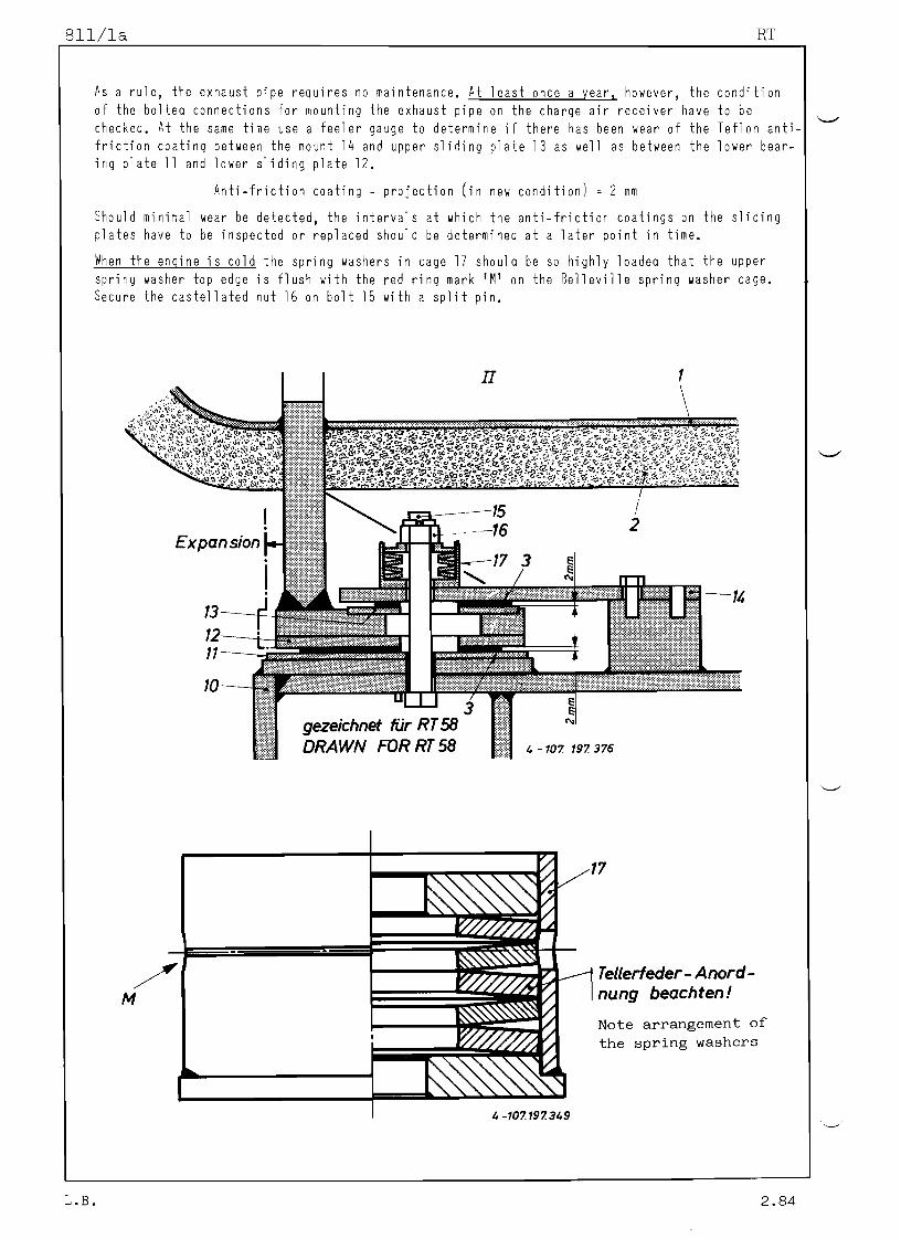
811/1a RT
As a rule, the exhaust pipe requires no maintenance. At least once a year, however, the condition of the bolted connections for mounting the exhaust pipe on the charge air receiver have to be checked. At the same time use a feeler gauge to determine if there has been wear of the Teflon antifriction coating between the mount 14 and upper sliding plate 13 as well as between the lower bearing plate 11 and lower sliding plate 12.
Anti-friction coating - projection (in new condition) = 2 mm
Should minimal wear be detected, the intervals at which the anti-friction coatings on the sliding plates have to be inspected or replaced should be determined at a later point in time.
When the engine is cold the spring washers in cage 17 should be so highly loaded that the upper
spring washer top edge is flush with the red ring mark 1M' on the Belleville spring washer cage. Secure the castellated nut 16 on bolt 15 with a split pin.
II
2 Expansion
1:'''-''�--14
4 - 107. 197. 375
17
/ Tellerfeder - Anord
nung beachten !M
Note arrangement of
the spring washers
4 -107.197. 349
L.B. 2.84

'..../
'/
SULZER
RT
HYDRAULIC CONDUITS FOR THE ACTUATION OF THE EXHAUST VALVES
Disconnecting and Mounting the Pipes
and Reconditioning the sealing Faces
Group: 846
Sheet: 1
Key to III ustra ti on
1 Suspension device 94833 * 1 Casing head (Ex- 10 Spacer 22 Cover I Milling/lapping 94834 haust valve hydrau- 11 Bolts w. nuts 23 Grease nipple
device lic header) 12 Screw 24 Bearing bush 1 Grease gun 2 Exhaust valve cage 13 Bolts w. nuts 25 Spi ndl e 1 All en wrench (AF6) 3 Actuator pump 14 Lantern 26 Milling cutter CARBORUNDUM Lapping paste 4,4a Steel ring 15 Simmerri ng 27 Allen screw No. 200 and 500} 5,5a,5b,5c Hydraulic conduits 16 Flange 27a Washer
end pieces 17 Allen screw 28 Clamp screw * = only necessary for RT76 a. RT8~ 6,6a Casing 18 Gri p' 29 Lapping mandrel
7,7a,7b,7c Shroud 19 Special nut OE Opening
8,8a Orings 20 Allen screw SF Spherical sealing9 Holding ri ngs
surface DISCONNECTING HYDRAULIC CONDUITS
Pay careful Attention to the following Points:
Take particular care that the sealing surfaces "SFI at the pipe ends are not in any way damaged. When separating the connections pull the pipe first axiall y out of the ring 4 or 4a and only then remove it sideways.
Protect the ends of the disconnected pipes by suitable measures against any possible damage and against any entry of dirt.
When removin~ complete conduit sections with the crane, utilise the suspension device (Tool No. 94833).
MOUNTING HYDRAULIC CONDUITS
Pay careful A t t ~ A t i 9 n ..to the..f.o1J9wing,Poin.ts: ..
Convince yourself that the sealing surfaces at the pipe ends as well as the seating face in the steel rings 4 or 4a are clean and absolutely undamaged.
Join the pipes to the component connection axially i. e. do not join them up sideways, so that any pos-sibility of damage to the sealing surface "SFI is avoided.
Screw the casings 6 or 6a on until landed, then turn them back by about! turn, whereupon the bolts 13' can be inserted and tightened.
When tightening the bolts 11, make sure that the distance IX· (see Fig. "C") is about equal on both sides.
RECONDITIONING SEALING SURFACES ISF"
Should the case occur that the sealing surface "SF" (Fig. B,C or D}requires reconditioning, utilise the
tool 94834 (see sheet 846/lc).
Remove the shroud from the conduit or push it back sufficiently to permit the pipe being fixed in a vise.
Where the spherical sealing surface is only roughened or slightly damaged use the tool 94834 assembled according to Fig. "F". Utilising a tap wrench drive the spindle 25 slowly. Apply some CARBORUNDUM lapping paste from time to time to the lappjng mandrel 29 and while lapping withdraw the spindel 25 in short in-tervals to relieve the lapping surface. Use lapping paste No. 200 for prelapping and No. 500 for fini-
shing.
RT (L.B) 1984

RT
Where the damages are more serious it may be necessary to lightly remill the spherical sealing surface of the pipe ends utilising the tool as shown in Fig."E". For this purpose mount the milling cutter 26 in-stead of the lapping mandrel 29. Rotate also in this case the spindle slowly and apply very moderate pres _ sure. The necessary milling pressure is achieved by corresponding twisting of the special nut 19 with the
grip bar 18.
For both cases utilise the tool in such a position that surplus lapping paste or milling swarf can fall our through the opening "DE" without assistance. Fix the tool with clamp screw 28.
Prior to each application use the grease gun to inject some grease through the grease nipple 23.
lQA4L.B.

RT846/1b
1
o
,@
1 2
'"
7c 5c
5b
7b
5
6a
®
7
SF
7a 5a
13
6a 8a
© 9 10
DJIm--- 12
8
@
5c
gezeichnet fur RT 68 DRAWN FOR RT 68 2 107. 199.691
L.B. 1984

846/1c RT
Friisen mit Werkzeug MILLING with Tool Nr. 9'83'
®
2 107. 199. 687 23a 25 OE 26 270 27 28
Schleifen mit Werkzeug N 9'83' LAPPING with Tool r.
®
2 107. 199. 688 25 29 OE270 27
L.8. 1984
28

Table of Contents
-'-"-------------------------------
Maintenance Instructions
Clearance Tables
lightening values for Bolt Connection.s
Weights
Maintenance Schedule
WorkSheets
ToolUsts

SULZER Group: 9LiOTOO L S
RT Explanation Sheet:
The tools required for erection and maintenance of the engine are divided into three groups as per the following "Tools Lists":
Standard tools
Recommended special tools
Special tools available on loan.
Under "Standard tools" are listed (from page 9401 onwards) the tools and devices required for normal maintenance work on the engine.
Under "Recommended special tools" (from page 94050 onwards) such tools and devices are mentioned which allow certain maintenance work to be done with more ease and in a shorter time, than with the standard tools. These tools can be ordered separately either with the engine or at a later date
"Special tools available On loan" are such tools (shown from page 94060 onwards) which are loaned for transportation and for erection of the engine. They are to be returned to the engine manufacturers after completion of engine erection.
A separate set of tools is issued for the exhaust gas turbo chargers which should also be stored separately from the engine tools.
When ordering additional tools or replacements, the code No. as well as the tool description including engine type must be indicated (see tools lists).
Notices for: 1) Arrangement and use of hydraulic presses
2) Storing maintenance and spares administra-tion for the pretensioning jacks as well as sectional drawings of these.
~
are to be found on the following sheets
3) General instructions for
tensioning jacks.
usage of pre-
-When oil must be added to the hydraulic pumps, the specification regarding oil quality issued by the
pump manufacturers must be followed.
198?

SULZER Group: 940
JACKS AND PUMPS68 RT 76 Sheet: aArrangement and Application
84
19
900kN
® ~ L'£ 100kN (RT 68. 76)lII>odf!/ ~. 230kN (RT 84)
lII> 4 ®h'00kN
6 !ll'K ~ 45kN
lII>Y
r:::=:1819
:::17 9 ~iARRANGEMENT OF JACKS AND ACCESSORIES
FOR WORK ON CAMSHAFT, SEE GROUP 42l~ 1107. 197. 397 05"':19
(]) = Tightening/Looseningthe tie rods, the thrust bolts of the crankshaft main bearing covers, the connecting rod bolts of the crank pin bearing and the crosshead bearing.
(]) = Removing the Fitting the crankshaft main bearing shells.
(£) = Loosening/Tightening the valve cage in the cylinder head.
(]) = Jacking out the cylinder liners.
(}) = Removing and fitting the crosshead bearing s~lls.
(£) = Loosening/Tightening the piston rod screws or nuts respectively.
® = Loosening/Tightening the split gear wheel on the crankshaft.
Qj) = Loosening/Tightening the exhaust valve spindle, the valve seat and the balancer.

SULZER
RT 6876
JACKS AND PUMPS
Arrangement and Application
Key to the Arrangement of the hydro jacks on sheet 9400 Tool Code No. ENERPAC
1 Hydr. jack 900 kn (9 Ot) 94950 CRL1002
2 Hydr. jack 500 kn (50t) 94936 RC506
3 Hydr. jack 100 kn (lOt) 94937J CRC106 4 Hydr. jack 100 kn (lOt) 94937a
5 Hydr. jack 45 kn (4,5t) 94938 CRC55
6 Locking valve (on jack 94937a) 94939J V66 7 Locking valve 94939a
8 HP Oil pump 700 bar 94931 P462
9 Air hydraulic oil 700 bar 94941 BPA20280
Group: g ~ . O
Sheet: OA
HOLMATRA OTC RARIPRES~
- RSL-1002 -
Z-51 F150SU YS-120-A BS-506-RM
C106C BS-106-RM-
- C55C -
V38-L 705-1M with-RP3-44
TW7000 Y-29-A-2-C RP-1404-2-1C
- Y-26-LD RP-703-AGpump
10 Air hydraulic oil pump 3000 bar 94942
11 HP oil pump SKF 226400 94931 a
12 Branch piece 94934a
13 Oi 1 branch pi ece 94934
14 Connecting piece 94933
15 Pressure gauge (0-1000 bar) 94932
16 Pressure gauge connecting part -
17 Connecting piece -
18 Coupling socket -- CR-400 A-118 Y-25-1 RP3-6A
19 Coupling pl ug -- CH-604 A-l19 Y-25-3 RP3-68
20 High pressure hose (1800 mm long) 94935 H-909 H2M Y-21-2 TR2-HS
21 High pressure hose (600 mm long) 94935a
24 Double nipple - '--'"
~
1 n 0/

SULZER Group: 940
HYDRAULIC PRETENSIONING JACKSRT76
Sheet: DBStorage, Care and Spares Stock
The pretensioning jacks forming part of the engine tool kit must be carefully stored, when not in use, in a dry, clean place, where they are protected from any damage. They have to be cleaned and greased before storage (the connections must be blanked off with dust caps). When stored for a longer period, or also when extensively used, the rubber Orings may become hard. We therefore recommend to ensure correct lorking to keep allays a number of Orings and slide rings of the prescribed Quality and dimensions in the engine store. When fitting new slide, rings pay particular care so as not to cause any damage to them. No sharp edged aid or tools may be used for assistance.
The sliding rings of the piston joint rings have to be heated in boiling later prior to fitting them!
The keys to illustrations belol refer to the pretensioning jacks sholn on the following pages:
Tool No. 94145 Tool No. 94180 Tool No. 94215
Pretensioning jack to Pretensioning jack to Pretensioning jack to the \ the foundation bolts and the tie rods cylinder cover studs ~ generator foundation
1 Vent SCfSl 4 Allan screl 3 Allan screl 2 Relief valve 5 Cylinder 10ler part 4 Connecti~g nipple 3 Jack nut 6 Cylinder upper part 5 Nut 3a Safety ring 7 Piston 6 Vent screl 3b Lock screl M6 7a Oring } to piston joint ring 7 Flange ring 4· Piston 7b Slide ring 360 x 352 x 5.8 8 Belleville spring lashers 4a ORing } to piston joint ring 7c Ori ng } to rod joi nt ring (39 pes. per bolt) 4b Slide ring 130 x 125 x 3.8 7d Slide ring 220 x 2~6 x 5.8 A35.5 x 18.3 x 1.25 x 2.8
4c ORing } to rod joint ring 8 Flange ring 9 Bolt 4d Slide ring 85 x 89 x 3.8 9 Belleville spring lashers 10 Gyl inder
11 Connecting nipple (41 pes. per bolt) 11 Piston B45 x 22.4 x 1.75 x 3.05 lla ORing l!0 piston joint ring
10 Bolts lIb Slide rin~ 250 x 244 x 5.8 11 Vent screw lie ORing Do rod joint ring
lld Slide rin~ 125 x 130 x 3.8
: Tool No. 94251 Tool No. 94252 './
Pretensioning jack to Pretensioning jack to
the exhaust valve the exhaust valve cage
1 Cyl inder 1 Cylinder 2 Pi ston 2 Piston
2a ORing } to piston joint ring 2a ORing } to piston joint ring 2b Slide ring 130 x 125 x 3.8 2b Slide ring 190 x 184 x 5.8 2c ORing } to rod joint ring 2c ORing } to rod joint ring 2d Slide ring 70 x 74 x 3.8 2d Slide ring 110 x 115 x 3.8 3 Flange ring 3 Fl ange ri ng
4 Bolt 4 Connedingnipple 5 Belleville spring lashers 5 Spacer ring
22 pes. per bolt 6 Pulling screl B28 x 14.2 x 1 x 1.8 7 Bolt
6 Connecting nipple 8 Belleville spring washers 7 Nut 32 pes. per bolt 8 Belleville spring lashers (4 pieces) B28 x 14.2 x l.x 1.8
B80 x 41 x 3 x 5.3 9 Vent screl 9 Vent screl 10 Threaded sleeve
11 Locati ng screw
9.84
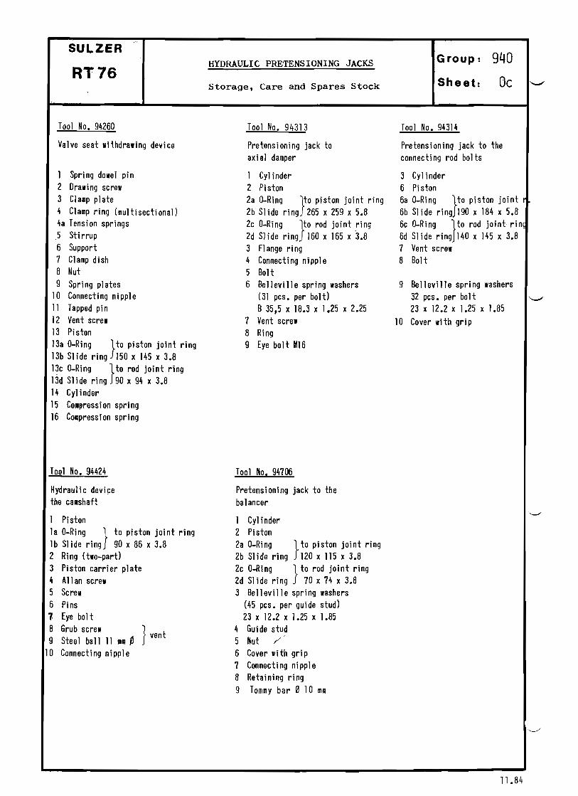
'-"
SULZER
RT76 HYDRAULIC PRETENSIONING JACKS
Storage, Care and Spares Stock
Group: g ~ O
Sheet: Oc
Tool No. 94260
Valve seat withdrawing device
1 Spring dowel pin 2 Drawing screw 3 Clamp plate 4 Clamp ring (multisectional) 4a Tension springs 5 Sti rrup 6 Support 7 Clamp dish 8 Nut 9 Spring plates
10 Connecting nipple 11 Tapped pi n 12 Vent screw 13 Piston l3a ORing }to piston joint ring l3b Sl ide ring 150 x 145 x 3.8 l3c ORing }to rod joint ring l3d Slide ring 90 x 94 x 3.8 14 Cyl inder 15 Co.pression spring 16 Compression spring
Tool No. 94424
Hydraulic devi~e
the camshaft
1 Piston la ORing } to piston joint ring lb Slide ring 90 x 86 x 3.8 2 Ring (twopart) 3 Piston carrier plate 4 A11 an screw 5 Screw 6 Pins 7- Eye bolt
8 Grub screw } 9 Steel ball 11 mm ~ vent
10 Connecting nipple
Tool No. 94313
Pretensioning jack to axial damper
1 Cylinder 2 Piston 2a ORing }to piston joint ring 2b Slide ring 265 x 259 x 5.8
2c ORing }to rod joint !ing 2d Slide ring 160 x 165 x 3.8 3 Fl ange ri ng 4 Connecting nipple 5 Bolt 6 Belleville spring washers
(31 pes. per bolt) B35,5 x 18.3 x 1.25 x 2.25
7 Vent screw 8 Ring 9 Eye bolt M16
Tool No. 94706
Pretensioning jack to the balancer
1 Cy1 inder 2 Piston 2a ORing }to piston joint ring 2b Slide ring 120 x 115 x 3.8 2c ORing } to rod joint ring 2d Slide ring 70 x 74 x 3.8 3 Belleville spring washers
(45 pes. per guide stud) 23 x 12.2 x 1.25 x 1.85
4 Guide stud 5 Nut /" 6 Cover with grip 7 Connecting nipple 8 Retaining ring
9 Tommy bar 0 10 mm
Tool No. 94314
Pretensioning jack to the connecting rod bolts
3 Cyl inder 6 Pi ston 6a ORing }to piston joint r
6b Slide ring 190 x 184 x 5.8
6c ORing }to rod joint rin~
6d Slide ring 140 x 145 x 3.8 7 Vent screw 8 Bolt
9 Belleville spring washers 32 pes. per bolt 23 x 12.2 x 1.25 x 1.85
10 Cover with grip
"-
11.84

~
SULZER
RT
HYDRAULIC PRE TENSIONINGJACKS
General Application Instructions
Group: 940
Sheet: 00
For distinct screwed connections differing designs and sizes of waisted bolts or studs are used, which are pretensioned by hydraulic jacks. The waisted fasteners have threads which extend over the nut; on this threadend the corresponding jack size is mounted. For each thread of the various waisted fasteners a sui table pretensioning jack is suppl ied in the engine tool set. The fasteners are pretensioned wi th the pretensioning jacks, the nuts are only threaded on manually until seated.
Prior to mounting the jzcks the inside thread of the jacks and the extending thread end of the fastener must bo cleaned with extra care. The thread must be undamaged and free working. The thread has to be smeared with MOLYKOTEGREASE.
Working Procedure for I.oosening
_ Thread the pretensioning jack by hand onto the extending thread end of the fastener to be loosened until it is firmly landed without any clearance on the component part. Now turn back the jack by (generally)! turn. Thp clearance thus obtained between jack and landing face on the component part is essential, before starting the pretensioning of the fastener. It enables the loosening of the nut till total relaxation of the fastener in one single work sequence.
_ Connect the pump and jack with the liP hose.
_ .Open the ventscrew on top of the jack a little (if existing).
_ Actuate the hydraulic pump. When the oil flows out bubblefree close the vont screw. The piston of the hydraulic jack has to be now in its neutral position, it must not be situated in either end position.
_ Raise the pressure with the pump te 600620 bar. The nut is now slack, loosen it with the round bar, while keeping the pressure censtant.
_ Release the pressure and disconnect the jack from the fastener throad.
Working Procedure for Tensioning
_ The nut(s) having already been firmly seated mark the position(s) of each of them against the nut landing on the component part, use a marking felt pen or similar; the marks arc later a reference for
judgeing the correct pre-tensioning.
_ Thread-on by hand the pre-tensioning jack onto the protruding thread end of the fastener until it is fully seated without any clearance between the jack and the component part.
_ It may be necessary to turn the jack back a little to gain easy access through the slot in the jack cylinder for manipulating the round bar to tighten the nut while the pre-tensioning is progressing.
_ Connect pump and jack by the HP hose.
_ Open the vent screw on top of the jack a little (if existing).
_ Actuate the hydraulic pump. Shut the vent screw when the oil flows out bubblefree. The piston of the hydraulic jack has to be now in its neutral position, it must not be situated in either end position.
_ Raise the pressure with the pump, in accordance with the indication on the tightening of important
screwed connections (group 013, sheet 1 and 21.
_ Keep the oil pressure constant on the specified value and using the round bar tighten the nut onto its seating surface until firmly seated. Check with tbe feeler gauge whether actually no clearance remains
between nut and seating. ,/
_ Release the pressure and unscrew the pre-tensioning jack, from the fasteners thread end.
_ Check with the referenced markings, whether all the nuts have been turned by the same angle. If marked differences are noted, the tensioning proc~dure must be repeated.
Remark: Concerning the use of air-hydraulic pumps and of thoir maintenance please refer to the makers instructions.)
'----'
9.88

940/0e RT76
94145
2 1
3
4
5
30
3b
0-107. 134.603 10
94180 9
M160
7 11 8 7a 7b
1-107.198.415
94215
8
9 10
2 107, 198.422
l1b
·5.84

9I,O/Of RT76
~
"--'
94251
6
7
5
' 3 2a
2 / 2b
2c
2d1
2107.197.015
2c
2d
-10
~-+-_-----L..:...1-107.197.080
11
94252
65 $: 9
" J
2
1 2a 2b
1984

940/0g RT76
94260
13
U
0-107. 199.692
~ . a /3b/
3d
. ~ 1 3 c
8
7
15
16 9
6
5
94313 ~ - 9
~ - 8
H+..
1 ~ - - 4
"l'-. .....-- 3
B2b
2 107 199 696
9.84

RT 76940/0h
94314
3-107.159.018
8
9
10
94424 I-I 7b
1
2
3
2 107. 198.419
9. 84

940/0i RT 76
94706
( ,3
1
6
-1---7
3 -107. 198. '28
11 .84

List of Tools for RT76 Engines
Code No. Description and
a lication 9401 Sketch
Open end/ring spanner
Spanner type 100
Spanner type 115
2 Pieces
" " " II
" " " " If
1 Piece
" " t1 "
" " " " .. "
1 Piece
SW 7
SW 8
SW 9
SW 10 SW 11
SW 12
SW 13
SW 14 SW 17
SW 19
SW 22 SW 24
SW 27
SW 30
SW 32
SW 36
SW 41 SW 46
SW 50
SW 55 SW 60
SW 65
SW 70
SW 75
SW 95
SW 105 SW 110
SW 185
1984

List of Tools for RT76 Engines
Code No. Description and
application 9402 Sketch
Spanner type 310
1 Piece SW 17
" " SW 19
" " SW 22
" " SW 24
Spanner type 330
1 Piece SW 27
" " SW 30
" " SW 32
SW 36 SW 41
SW 46
SW 50
SW 55
SW 60
SW 65
SW 70
" " sw 75
" " sw 85
" " sw 95
" " SW 110
" " sw 115
1 Impact ring spanner
AF 130 •• ()
Spanner type 360
1 Piece SW 19
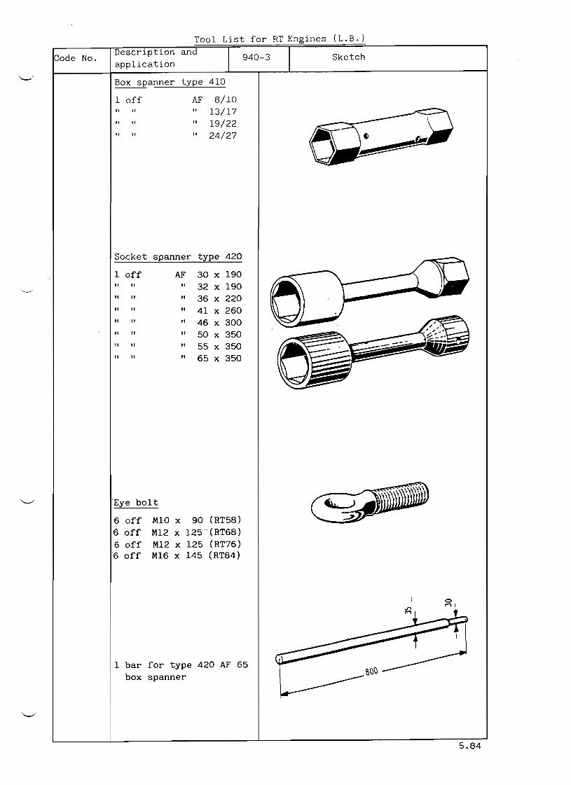
Code No.
~
Tool List for RT Engines (L.B.)
Description and Sketch9403
application
Box spanner type 410
1 off AF 8/10
13/17 "" " 19/22"" " 24/27"" "
Socket spanner type 420
1 off AF 30 x 190
" 32 x 190
36 x 220
41 x 260
46 x 300
50 x 350
55 x 350
65 x 350
Eye bolt
6 off Ml0 x 90 (RT58)
6 off M12 x 125(RT68)
6 off M12 x 125 (RT76)
6 off M16 x 145 (RT84)
1 bar for type 420 AF 65
box spanner
5.84

Tool List for RT Engines (L.B.)
Description and Code No.
application 9404 Sketch
Spanner type 450
1 off AF 11
" " 12
" " 14
17 "" 19 "
" " 27
32
"
" " " "
41
" 50 " 60 ""
Allen key type 460
1 off AF 5
" " 6
8 " " 10
12
14
17
19
22
24
27
Screw driver type 110
1 off b 6,5 mm ,----,'~ j ¥ )b 8" " = " " " b = 10 "
" b = 13 "" " " b 16 " " " b 18 "
Right angle screw driver
type 410
1 off b = 10 mm
" " b "13
" " b " 17
" " 25 b "
1983

List of tools for RT76 Engines
Description and 9405 SketchCode No.
a lication
"Seeger" Circlip pliers
1 pes. Type A 1
" A 2" " ~ ..~.. ! .A 3"" "
1 pes. Type J 1
" " " J 2
" " " J 3
Eye nut
4 pes. M 45
(for the suspension of
the fuel injection pump)
Eye screw
8 pes. M 10
M 12
M 16
M 20
M 24
M 30
M 36
4 M 48
1984

Tool List for RT Engi'1es (L. B. )
Description and 9406 SketchCode No.
application
Grip screw
( ~2 off M 4 x 150
M 5 x 150 " " M 6 x 150 " " 1'1 8 x 150" " M 10 x 150 " "
. ---~ -
Extracting device for ta- ~(!l ~ pered and cylindrical do-
wel pins
1 off M 6 II II M 8
" II M 10
" II M 12
Jacking screw
4 off M 16 x 160
" II M 20 x 100
Highpressure grease gun
For the grease nipples on
the fuel injection pump
regulating linkage
1983
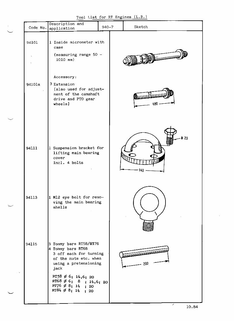
94113
Tool List for RT Engines (L.B.)
Description and 9407 SketchCode No. application
94101
94101a
94111
1 Inside micrometer with
case
("measuring range 50 -
1010 mm)
Accessory:
3 Extension (also used for adjust-
ment of the camshaft
drive and PTO gear
wheels)
jM20 1 Suspension bracket for ~l .
lifting main bearing
cover Incl. 4 bolts
r-----:" 140 _J
1 M12 eye bolt for remo-
ving the main bearing
shells
3 Tommy bars RT58/RT.76
4 Tommy bars RT68 3 off each for turning of the nuts etc. when using a pretensioning
jack
RT58 ¢ 6; 14,6; 20 RT68 ¢ 6; 8 14,6; 20 RT76 ¢ 8; 14 20 RT84 ¢ 8; 14 20
/
94115
10.84

Tool List for RT Engines (L.B.)
Code No. Description and
application 9408 Sketch
94117 1 Roller support for remo-
ving main bearing, com-
prising:
1 Support
1 Roller
1 Eye bolt
1 Split pin 5 x 56
1 Bolt M 30
1 Pin ¢ 35
114
1 Device for removing the
main bearing shells
x == 270 (RT58)
X z:: 320 (RT68)
X 375 (RT76)
X == 410 (RT84 )
94118
x
2 Wire ropes for removing
main bearing shells
X 2700 mm (RT58)
X == 3200 mm (RT68)
X 3700 mm (RT76,RT84)
94119
X
5.84

Tool List for RT Engines (L.B )
Code No. Description and
application 9409 Sketch
1 Feeler gauge94122
94123 1 Special feeler gauge
for main bearings / I 6~O ~~rfP· ~ 625---·~r
94124 1 Depth gauge
Measuring range
250 mm
to
94126 1 Depth gauge
Measuring range
RT 58, 68, 76 = 500
RT 84 = 700
mm
mm
~ .......,~ ~
~.~~ ~ '.
~ ......
11.84

94010
Tool List for
Description a lication
1 Support for removal of the main bearing shells
X 872 mm (RT58) X 1036 mm (RT68) X =: 1150 mm (RT76) X 1286 mm (RT84)
1 Pretensioning jack for foundation bolts
X 132 mm (RT58) X 132 mm (RT68) X 150 mm (RT76) X = 150 mm (RT84)
1 Casing cover (only supplied when en-gine is fitted with a PTO)
X 1180 mm (RT58) X 1325 mm (RT68) X 1556 mm (RT76) X 1725 mm (RT84)
1 Turningout stud with nut for removal of thrust bearing pads (For engines with gear wheel for camshaft drive fit-ted on thrust bearing flange
X = 155 mm (RT58) X 175 mm (RT68) X 185 mm (RT76) X = 190 mm (RT84)
1 Turningout device for removal of thrust bea-ring pads (For engines with gear wheel for cam-shaft drive fitted on crankshaft coupling flan ges)
X 300 mm (9+12 RT76) X =: 316 mm (8+12 RT84)
Code No.
94141
941215
94146
94155
94155a
(L.B.)
Sketch
x
1.85'

••
List of Tools for RT76 Engines
Description and 94011 SketchCode No.
application
~ ~ - - 4 4 52 Hydraulic pre. tension-94180 ing jacks for the tie
rods
1 Transport device for
cylinder liner with cy-
linder jacket
94201
1 Suspension girder94202
2 Web support94203
1 Jacking girder94204
1 Jack support94205
2 Suspension straps with
2 screw 94206
2 Special screws for fas-
tening the straps
94206 to the cylinder
liner
94207
h - - - - . - - = ~ - - - - . - : . ' ~ 942 ~ 1 '"lic:::::::r
94206
94205
1984

:c21 ! ist for RT Engines (L.B.)
ana 94011a SketchCode No.
94215 1 Hydraulic tensioning de-
vice with connecting
parts for tensioning the
cylinder head stud
bolts:
a tensioning jacks
b = air hydro pump (see
also Sheet 94041,
Code No. 94941)
C :: highpressure hose
d compressed air hose
30 m long (also use
for tool No. 94264)
e suspension device
94224 Ladder for measuring cy-
linder liner bore
x = 3050 mm
(only for RT76 and RT84)
94225 1 Calibration guide for X
]measuring cylinder li I" ner bore (together with 51
micrometer, see 94101)
x = 2125 mm (RT58)
x :: 2410 mm (RT68)
x 2650 mm (RT76)
x = 2900 mm (RT84)
1 Set of feeler gauges
(10 blades) for checking
bearing clearances
blade length = 600 mm
blade thichness = 0.05-
0.100.150.200.25-
0.300.400.500.60-
94238
0.80 mm 12.87

List of Tools for RT76 Engines
Code No. Description and
a lication 94012 Sketch
94250 1 Gland bore cover plug,
including 4 latches
with spring washers,
nuts and heavy roll pin
X = 395 mm
94251 1 Pretensioning device
for the exhaust valve
X = 214 mm
94252 1 Hydr. pretensioning
device for the valve
cage consisting of:
4 Pretensioning jacks
and connecting stirrups
X = 1020 mm
Ii II II II
1984

List of tools for RT 76 and 84 Engines
Code No. Description and
application 94013 Sketch
94259 1 Pressure pin to the
exhaust valve
RT76 L= 535
RT84 L= 575
94260 1 Valve seat removal
device
RT76
RT84 L= 642
L= 692
94261 1 Valve seat fitting
device
RT76
RT84
L= 640
L= 680
94262 1 Valve protection (only
for transportation of
a complete exhaust val-
ve is it necessary to
mount the protection)
RT76
RT84
L= 595
L= 650 L
9,84

List of Engines- - - ~ - - - : - ~ - ~ ; ' ; " ' - - F ; ; ; ' ; ; " ~ ~ ' ; " ; " ' ~ ~ ~ - - - - - - , " _ ' " .. ,~ .. ~ i (Description and
\ Code No. !application Sketch , ;....-----+-...:..:---------.....&---r'--...L..----------------·~~·i
194263 11 Fitting and removing I
, ' vice for the guide ,1,,1- . \~. ~ I l consisting of:
2 Screw
I\
E f ~2 Nuts
! I ,l
~ .~
I
" 94265 11 Suspension device to the
Cylinder head
to that
3 Caps 'a'
for protection of
cylinder head studs
94266 1 Suspension device to the
valve cage
94267 2 Jacking devices for the I
I I @
Ivalve cage !
I L-_....L...- L....- ..,_J

Tool List for RT Engines (L.B.)
Kode No.
94269
94270
94271
Description and
application 94015
Hydraulic tightening de
vice for nut of the fuel
injector nozzle
comprising:
a) 1 Special spanner
b) 1 Hydr. jack
(e.g. ENERPAC type
RC-55)
c) 1 High-pressure oil
hand pump (e.g.
ENERPAC type P-14)
(accessories for
L'ORANGE test stand
94272)
1 Device for overhauling
the fuel injector seat
in the cylinder head
Protection cap for fuel
nozzle
RT 58/68 . 3 Pieces per cylinder
RT 76/84 4 Pieces per cylinder
X=60mm
Sketch
1.89

Tool List for RT 76 Engines
Code No. Description and
application 94016 Sketch
94272
94273
1 Valve testing stand
l'ORANGE Type GXOG004
For setting and testing
of;
Fuel injection valves,
(the circulating valve
for separate testing)
Relief valves of the
cylinder heads Relief
valves and static pres-
sure regulating valves
of the fuel injection
pumps.
x == 1100 mm
1 Mounting angle for fix-
ing the fuel injection
valve on the l'ORANGE
test stand
x = 320 mm
94274 1 Screwed connecter piece
with blow through valve
and hose connections
for the setting and
testing of a fuel injec
tion valve.
X = 230 mm
Additional parts:
94274a 1 Copper bend piece
94274b 1 Hose piece 1 m long
94274c 1 Testing device for the
circulating valve
X = 150 mm
b
8.86
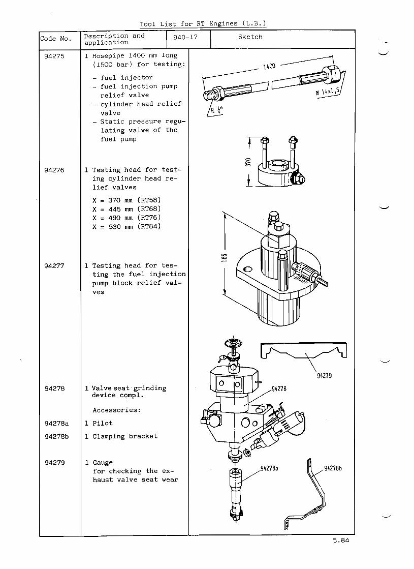
Tool List for RT Engines ( L ~
rescription and Sketch94017Code No. application
1 Hosepipe 1400 mm long
(1500 bar) for testing: 94275
fuel injector
fuel injection pump
relief valve
cylinder head relief
valve Static pressure regu-
lating valve of the
fuel pump
1 Testing head for test-
ing cylinder head re-
lief valves
94276
x = 370 mm (RT58)
X = 445 mm (RT68)
X = 490 mm (RT76)
X = 530 mm (RT84)
1 Testing head for tes-
ting the fuel injection
pump block relief val-
ves
94277
1 Valve seat· grinding device GC?mpl.
94278
Accessories:
1 Pilot94278a
1 Clamping bracket94278b
1 Gauge
for checking the ex-
haust valve seat wear
94279
5.84

Tool list for RTEngines (L.B.)
Description andCode No 94018 Sketchap lication
Exhaust valve retaining
frame with swivel device
(To be used when dismant-
94290
RT58 ling, assembling or grin- RT68 ding)
X 1200 mm RT58
X 1200 mm RT68
I---------X------~
x = 1500 mm RT76
X 1600 mm RT84
1 Gauge
for checking the wear of
exhaust valve head
94292
X = 80 mm RT58
X = 85 mm RT68
X = 90 mm RT76
X = 100 mm RT84 o 1---- X -----<-.
1 Special spanner for re-
moval and fitting of starting valve seal in
cylinder head
94293
1-------- X --------i
L.B. 1.85

94296
94305
Tool List for RT Engines (L.B.)
Description and 94019 SketchCode No.
Application
1 Device for tensioning
the spring of the star-
ting valve, consisting
of:
94294
1 Plate
2 Tensioning screws ><
X 253 mm (RT58)
X 203 mm (RT68)
X 253 mm (RT76)
X ::: 253 mm (RT84)
(RT58) M16 Jl (RT68) M 10
(RT76) M 12
(RT84) M 12
2 Jacking screws for the withdrawal of the star-
ting valve from the cy-
linder head for RT58, RT76, RT84
94296
1 Jacking device for the
starting valve, with
2 Screws
for RT68
1 Checking set (in wooden
box) for measuring the ,e ~ ~ crankshaft deflection.
l - - - - - ~ - - 364 .1
1 Suspension device for
the connecting rod
Including 4 screws
X 350 mm (RT58)
X ::: 410 mm (RT68)
X ::: 460 mm (RT76)
X ::: 530 mm (RT84)
5.84
94311

Tool List for RT76 and 84 Engines
Description and 94020Code No. application
94312
94313
94314
1 Suspension bracket for
piston of axial
damper
(Only supplied for
engines with axial
damper)
1 Pretensioning jack for
tensioning the central}
located tension bolt ~ ('0")
of axial damper
(Only supplied for
engines with axial
damper)
2 Pretensioning jacks for
tensioning of lower and
upper connecting rod
bolts
x 121 238 mm (RT76)
X = 121 248 mm (RT84)
--+--+
Sketch
x
2 Holding brackets for94317 lower connecting rod
>< 1bearing
L.~incl. each 2 bolts M24
and I threaded tube of
1300 mm length

List of tools for RT76 Engines
Code No. Description and
application 94021 Sketch
1 Holding stirrup for se
curing the bearing
upper parts of the
crosshead bearings dur
ing a bearing inspectio
94320 3 Supporting pipes to .' .. prop up the crosshead
0 0 •
".:J'
during a bearing inspec --- ..
tion: '/;
1 pc. L 304 mm
1 pc L 456 mm L
1 pc L 608 mm
( b) (a)
94321 3 Intermediate pieces to
raise the base of the
qydnaulic jack for a
crosshead bearing ins
pection
1 pc L 24 mm ( a) L
1 pc L 162 mm (b)
1 pc L = 314 mm (b)
94319
94322 1 Fastening device for
the connecting rod
shank
o
1------ 1510 -----I
94323 4 Stop pins to prop-up
the crosshead guide
shoes when removing or
fitting a connecting
rod or a crosshead
94324 1 Suspension device for
the crosshead, with or
without the connecting
rod. It also serves as
filler piece or oil spa
ce sealer on the cross
head, when the engine
has to be operated with
out that respective
working piston.
944----
5.84

List of tools for RT76 Engines
Description and 94021 SketchCode No.
application
94319 1 Holding stirrup for se-
curing the bearing up-per parts of the cross-
head bearing during a
bearing inspection.
3 Supporting pipes to prop up the crosshead
during a bearing ins-pection 1 pc L = 354 mm 1 pc L = 506 mm 1 pc L = 658 mm
94320 ~ ~.
.1. ~
L
'"--,,
1984
(b)
94321 3 Intermediate pieces to
raise the base of the hydraulic jack for a
crosshead bearing ins-
pection 1 pc L 24 mm (a)
'-"--L1 pc L = 162 mm (b)
1 pc L = 314 mm (b)
94322 1 Fastening device for
the connecting rod
shank 1510
o
94323 4 Stop pins to prop up
the crosshead guide shoes when removing or fitting a connecting
rod a crosshead
94324 1 Suspension device for
the crosshead,
K.Kstg.
with or without the con
necting rod. It also serves as filler piece or oil space sealer on
the crosshead, when the
engine has to be opera-
ted without that res-pective working piston.

Tool List for RT Engines (L:B:)
Description 94022 SketchCode No. a lication
1 (Impact) spanner for
tightening the connec-
ting pieces of the pis- ton cooling telescoping pipes in the piston rod
94329
X 290 mm (RT58/68)
X = 295 mm (RT76/84)
1 Template gauge for
checking the parallelity
of the piston cooling
telescoping pipes
94330
X 205 mm (RT58)
X 230 mm (RT68)
X = 255 mm (RT76) ><
X = 275 mm (RT84)
1 Pressure testing device
for the working piston
consisting of:
94331
a) 2 Pressure test nip-
ples with Oring
b) 1 Brazing ring to c S\II 50 (RT58/68)
S\II 70 (RT76/84)c) 1 Vent valve
X = 56 mm (RT58/68)
X 70 mm (RT76/84)
5.84

Tool List for HT Engines (L.B.)
Description andCode No. <)110- 2) Sketchapplication
1 Tensioning device for fitting and removal of piston rings
94))8
2 Clamping devices for piston cooling teles-copic.pipes (when trans-porting a piston or during piston removal)
94339
X = 576 mm (RT 58) X = 676 mm (RT 68) X = 756 mm (RT 76) X = 8)6 mm (RT 84:)
94:)4:1 1 Piston suspension bracket
X = 4:)9 mm (RT 58) X 576 mm (RT 68) X 567 mm (RT 76) X 520 mm (RT 84:)
RTS8rRT 68 RT 76
.
RT 76
1''-
\'
x
RT 8~
x
L.B. 9.87
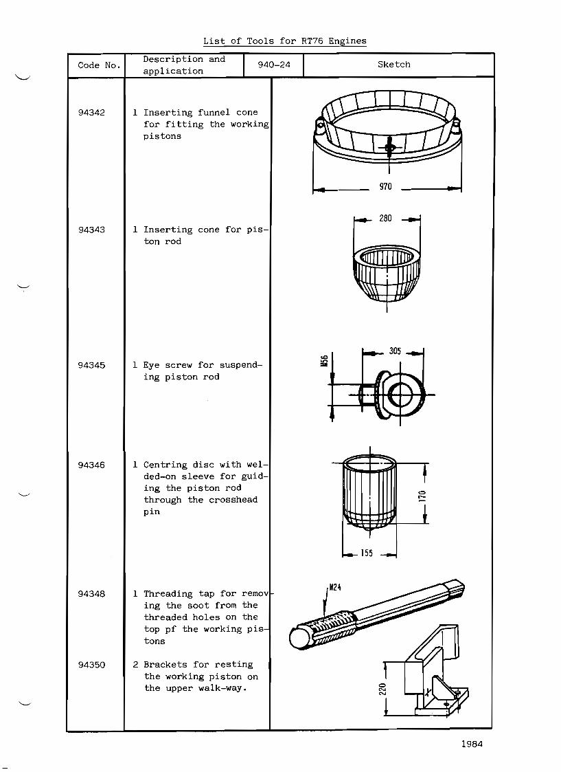
List of Tools for RT76 Engines
Code No. Description and
application 94024 Sketch
94342
94343
94345
94346
94348
94350
1 Inserting funnel cone
for fitting the working
pistons
1 Inserting cone for pis-
ton rod
1 Eye screw for suspend-
ing piston rod
1 Centring disc with wel-
dedon sleeve for guid-
ing the piston rod
through the crosshead
pin
1 Threading tap for remov
ing the soot from the
threaded holes on the
top pf the working pis
tons
2 Brackets for resting
the working piston on
the upper walkway.
970
:;00 ......
f 0. <"'
1 -..:
__ 155 __
1984

List of Tools for RT76 Engines
Code No. Description and
application 94024 Sketch
94342
94343
94345
94346
94348
94350
1 Inserting funnel cone
for fitting the working
pistons
1 Inserting cone for pis-
ton rod
1 Eye screw for suspend-
ing piston rod
1 Centring disc with wel-
dedon sleeve for guid-
ing the piston rod
through the crosshead
pin
1 Threading tap for remov
ing the soot from the
threaded holes on the
top pf the working pis
tons
2 Brackets for resting
the working piston on
the u p p ~ r walkway.
970
......
f co , t'-
t -..::
10-- 155 __
1984

List of Tools for RT76 Engines
Description and Code No. 94025 Sketch
Application
94356 1 Tightening device for
loosening/tightening
the piston rod nut or
the piston rod screw
respectively, consist-
ing of:
a) 1 Holder for the hy-
draulic jack
b) 1 Special spanner
with spanner hold-
ing pin ' c '
(In addition required,
HP oil pump and jack as
shown on sheet 9400
and Oa)
94363 2 Long jacking screws to
separate the piston
upper part from the
lower part
94364 2 Screws for separating
the piston rod from the
piston lower part (uti-
lizing also jacking (UI~LIIII!II !~;;;;;;;;;;~~screw 94363) I....------- 450 --------j
94366 1 Template for piston top
outline X == 812 mm f----------,x--------.-l
•
L )
6.87

Tool List for RT Engines (L.B.)
Description and Sketch94026Code No. application
1 Draw bolt for the pisto
cooling stand pipes
incl. 1 collar nut
94381
2 Sealing covers for blan .
king off the piston
cooling pipe glands (fo
emergency running)
each comprising:
94391
~
1 Cover with gasket
2 Latches
2 Nuts with spring
washers
2 Heavy type dowel pins
X 95 mm (RT58)
X = 95 mm (RT68)
X = 100 mm (RT76)
X 100 mm (RT84)
2 Sealing plugs for clos- _
ing off the piston cool
ing chest (for emergency running)
94395
X 83 mm (RT58) Lx X = 83 mm (RT68)
X 90 MM (RT76)
X = 90 mm (RT84)
5.84

List of tools for RTEngines (L.B.)
Description and 94027 SketchCode No.
application
2 Adjusting devices to
the intermediate gear
wheel X 245 mm (RT58)
X 245 mm (RT68)
X 250 mm (RT76)
X 250 mm (RT84)
94410
In addition 8 pins (ex-
changeable) for interme-
diate gear wheel for the
P.T.O.transmission
(if provided) Inside mic-rometer, see 94l0la.
1 Tightening device for
the gear wheel on the 94412
><
crankshaft, consisting
of:
1 Socket spanner
X = 634 mm, AF70 (RT58)
X = 798 mm, AF80 (RT68)
944l2a
x X = 824 mm, AF85 (RT76)
X = 930 mm, AF95 (RT84)
1 Spanner
X = 235 mm, AF70 (RT58)
X = 370 mm, AFSO (RT68)
X = 405 mm, AF85 (RT76)
X = 541 mm, AF'35 (RT84)
944l2b
1 Plate with 2 pins
X = 450 mm (RT58)
X = 507 mm (RT68)
X = 560 mm (RT76)
X = 584 mm (RT84)
944l2c
.... X /
/'
11.84
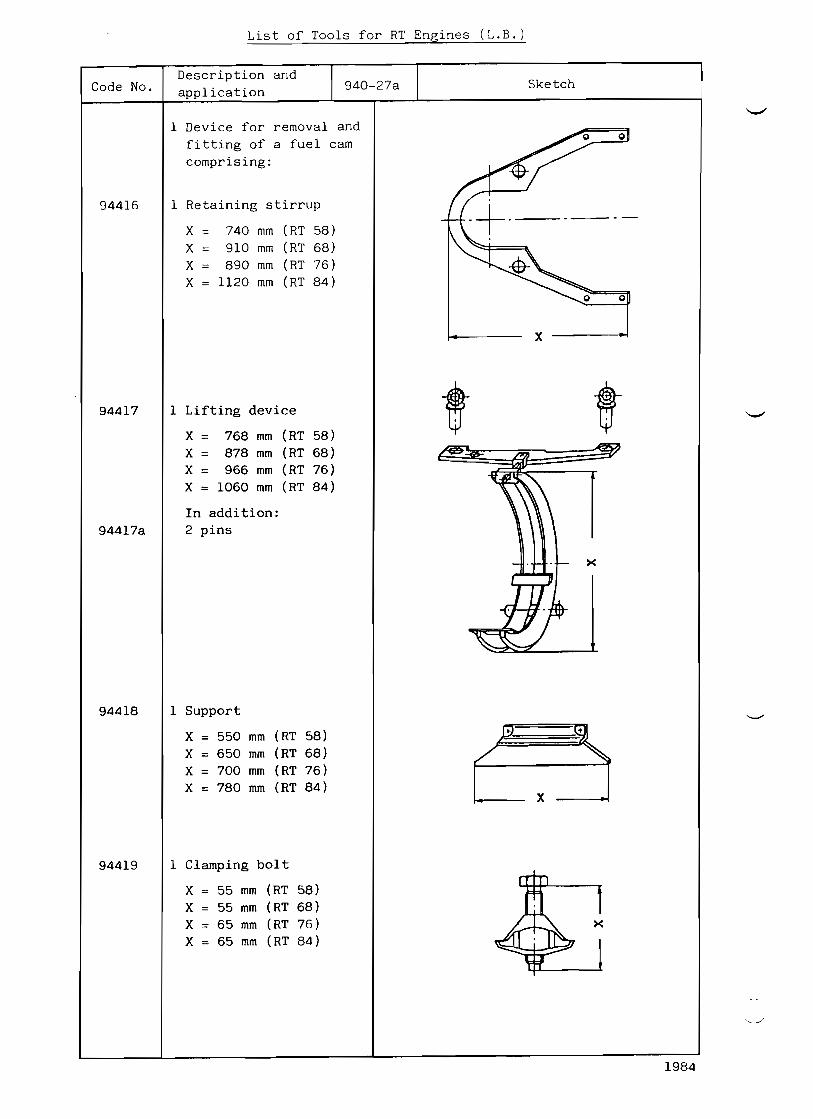
List of Tools for RT Engines (L.B.)
Description and 94027a SketchCode No. application
1 Device for removal and
fitting of a fuel cam
comprising:
1 Retaining stirrup94416
X 740 mm (RT 58)
X 910 mm (RT 68)
X 890 mm (RT 76)
X H2O mm (RT 84)
X
1 Lifting device94417
X = 768 mm (RT 58)
X = 878 mm (RT 68)
X = 966 mm (RT 76)
X = 1060 mm (RT 84)
In addi tion:
94417a 2 pins
x
1 Support94418
X 550 mm (RT 58) .. II,
X = 650 mm (RT 68) /X = 700 mm (RT 76)
X 780 mm (RT 84) X
1 Clamping bolt
X 55 mm (RT 58)
X 55 mm (RT 68)
X = 65 mm (RT 76)
X 65 mm (RT 84)
94419
1984

List of Tools for RT76 Engines
Code No. Description and
application 94028 Sketch
94420 2 Holding stirrups to
block the camshaft driv
ing gear wheel
94421 Mounting device for re-
moving and fitting the
camshaft driving gear
wheel on its shaft jour-
nals, consisting of:
2 Supports
2 Screws 'a'
2 Screws 'b'
94422 2 Holding straps for
blocking a camshaft
section
= cc cc
94423 Mounting device for re-
moving or fitting a cam-
shaft section, consistin
of:
2 Supports
2 Nuts 'a'
1984
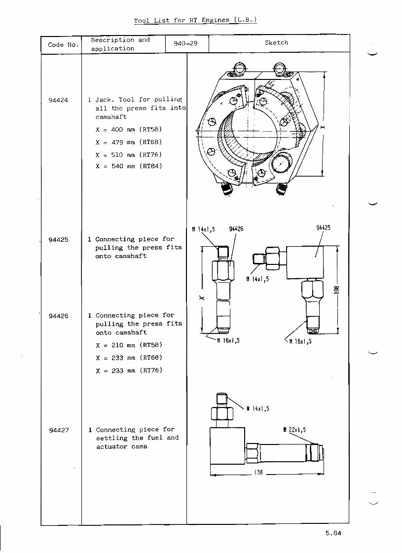
Tool List for RT Engines (L.B.)
Code No. Description and
application 94029 Sketch
94424 1 Jack. Tool for pulling
all the press fits into
camshaft
X 400 mm (RT58)
X 479 mm (RT68)
X 510 mm (RT76)
X 540 mm (RT84)
94425 1 Connecting piece for
pulling the press fits
onto camshaft
M14xl,5 94426 94425
94426 1 Connecting piece for
pulling the press fits
onto camshaft
X = 210 mm (RT58)
X 233 mm (RT68)
X 233 mm (RT76)
94427 1 Connecting piece for
settling the fuel and
actuator cams
1-1..._-- 138 411
M14xl,5 co o
M16xl,5
M14xl,5
III 22xl,5
5.84

94428
Tool List (L.B. )
Description andCode No.
application
1 Centering disc for posi-
tioning the jacking tool
94424 on the camshaft
when pulling on a flange
coupling of the balancer
or torsional vibration
damper
X 230 mm (RT58)
X 270 mm (RT68)
X = 300 mm (RT76)
X 330 mm (RT84)
94429 1 Hose pipe (1500) bar
Sketch
><
,eOO
I I i
_ i
:d
1 Device for cutting out
an actuating pump
(1 off per pump)
94430
1 Suspension strap for the
actuator cam and the
fuel cam with
1 screw
94431
94432 1 Gauge
for setting the cams
X 390 mm (RT58)
X = 450 mm (RT68)
X 510 mm (RT76)
X 545 mm (RT84)
I I I
1/
11.84

Tool List for RT Engines (L.B.)
Description and 94030a Sketch
c
Code No.
94451
94461
application
1 Extracting device for
starting control pilot
valve bush
comprising:
a) 1 Flange
b) 4 Threaded bolts M12
c) 1 Jacking screw
1 Pressure Gauge applian-
ce Logic Box
a) Pressure Gauge
o 63 0 + 10 bar
b) MinimessPressure
Gauge Connection
c) MinimessHigh Pressu
re Hose L 400
d) Hex. Head Screw
Driver
I ~ .. 114.........,1
a
b
1985

Tool List for RT Engines (L.B.)
Description and 94031 SketchCode No.
application
94534
94551
94552
1 Spacing tube to hold the shutdown servomo-tor in its service po-sition when adjusting the regulating linkage 190
(when no control air is
available)
1 Spanner for backing union of the guide bush of the fuel injection
pumps
X = 610 mm (RT58)
X = 610 mm (RT68)
X = 625 mm (RT76)
X = 625 mm (RT84)
1 Device for measuring the plunger stroke of
the fuel injection
pumps
incl. 2 bolts
2 Devices for measuring the stroke of the fuel
\ :injection pump suction
l----330~and spill valves
incl. 2 bolts each
94554
5.85

94555
Tool List for HT Engines (L.B.)
Description and 94032Code No. application
94556
94557
3 Special spanners for
setting the fuel lnJec-
tion pump suction and
spill valves
1 Special ring spanner for
fuel injection pump re-
lief valve
L = 250 HT 76 a. 84
L = 350 RT 58 a. 68
2 Special spanners for 1 L
setting the fuel injec-
tion pump suction and
spill valves
Sketch
94558 3 Spacers for laying unde
the push rode of the fuel injection pump suc
tion valves (fuel charg
reduction)
94559 1 Torque wrench with hex.
socket and extension fo
tightening the bolts of
the fuel injection pump
valve covers
94560 1 Blocking device for ec-
,
RI 'R=_.L....8
~ l E o = = = = = : : r ) I!iN:IOWl~s:Jee.fiiI'lJ]J
centric shaft (1 off
each per pump block, fo
fitting and transport)
x 490 mm (RT58) x X = 520 mm (RT68)
X = 540 mm (RT76)
X = 580 mm (RT84)
11.84

94561
Tool List for RT Engines (L.B.)
Code No.
94564
94565
94566
94567
94571
Description and 94033
application
1 Withdrawing device for
seats of fuel injection
pump spill valves (for
7 mm bore)
1 Withdrawing device for
suction and delivery
valve seats of fuel in-
jection pump
(for 8 mm bore)
1 Centering ring for lap-
ping cylinder tToor"'No.
94567)
1 Lapping cylinder for
sealing faces on fuel
injection pump body
(for valve covers)
1 Lapping cylinder for
sealing faces of fuel
injection pump valve
covers
1 Wrench for backing
union of fuel injec-
tion pump valves
1 Adjusting device for
the static pressure
regulating valves
Sketch
108
...
80
5.84
94572
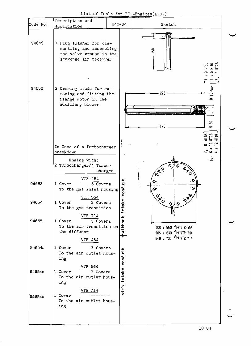
List of Tools for RT Engines(L.B.)
Code No. Description and
application 94034 Sketch
94645 1 Plug spanner for dismantling and assembling Cl
Lr>
the valve groups in the scavenge air receiver
= = <.CLr> c.o C"'-o 0 0n: c::: ~
en <.C Lr> .. .. ~ ...,.. ...,.. ...,..
L...,,J
94652 2 Cenring studs for re <-0
'+
moving and fitting the 225 c.o
flange motor on the ::e
auxiliary blower "
Cl C'I
320 ::e
~ = c.o ...,.. c.o r- = 0 0 0e::: e::: e:::
In Case of a Turbocharger ~ ~ = ~ ~
breakdown r- ". . <0 ...,..
<-
Engine with: 0 '+
2 Turbocharger/4 Turbo
charger
VTR 454 +l
94653 1 Cover 3 Covers 'M :l
To the gas inlet housing '0 s:: 0
VTR 564 0
(IJ
94654 1 Cover 3 Covers ~ ell
To the gas transition +l s::
'M
VTR 714 +l
94655 1 Cover 3 Covers :l 0
To the air transition ..0 on "400 .. 550 for YTR 454+l
the diffusor 'M
505 .. 630 fo r YTR 564:it
VTR 454 640 .. 735 forYTR 714
94654a 1 Cover 3 Covers +l
To the air outlet hous 'M :l
ing '0 c 0
VTR 564 0
(IJ
94654a 1 Cover 3 Covers ~ ell
To the air outlet hous +l s::
ing 'M
.c VTR 714 +l
'M
Cover :it95654a --------
To the air outlet housing
10.84
''

List of Tools for RT76 Engines
Code No. Description 81d
application 94036 Sketch
94661 Shifting device for re
moving and fitting a
cooler stack of a sca
venge air cooler, con
sisting of:
94662 1 Roller plate with
4 screws M 20
94663 1 Plate
with 3 screws M20
for
Cooler Type:
GEA-K 202/27/10/2 or
SERCK-K lOA
230
94663a 1 Plate
with ~ screws M20
for
Cooler Type:
GEA-K 275/32/10/2 or
SERCK-K lOA
94664 1 Support with roller
with 4 screws M24
94667 1 Eye screw M30
1l.8~

(for engines with P.T.O.) TOOL LIST FOR RT ENGINES
Code No.
94701
Description and ap lication
94037
2 Spurwheel crane trolley
(lifting capacity = 5 t) for assembly and dismant ling work on the P.T.O.
Sketch
f4ca. 650
L. B. 1984

(For Engines equipped with Balancer)
List of Tools for RTEngines (L.B.)
Code NO.
94704
94705
94706
"'
94707
94708
Description and 94038 Sketch
application
Rivet puller with spanner
'a' and round bar 'b' to
the roller chains
b
/
Assembling tool for the
chain lock link on the
roller chains
1 Pretensioning jack
for the screw fasten-
ing of the balancer
housing 1st order to
the end column
L = 140 mm RT 68 a. 76
L = 160 mm RT 84
L
2 Locking bolts
(only for balancer 1st
and 2nd order
X =: 281 mm (RT68)
X =: 311 mm (RT76)
X = 321 mm (RT84)
2 Rails with 4 screws
each (Only for balan-
cer 1st and 2nd order)
X = 1060 mm(RT68)
X 1260 mm(RT76) X =: 1450 mm(RT84)
11.84

(',;Ji th EfficiencyBooster)
Tool for RT Engines (L.B.)
Description and SketchCode No. 94038a a lication
Mounting device for the
hydraulic coupling 94751
X = 580 mm
Withdrawing device for the
hydraulic coupling 94752
X = 0 510 mm a = Allen screw M 30
Monting device for flexi-
ble packet coupling 94753
X = 380 mm
Withdrawing device for
flexible packet coupling 94754
X = 0 210 mm for 650 TC X = 0 240 mm for 750 TC X = 0 275 mm for 866 TC
a = Allen screw M24
4.87

(With EfficiencyBooster)
Toc1 List for RT Engines (L.fr.)
x = 740 mm
Sketch
Vi,/,1 . ~ .J
94038bescription and pplication
Rest for hydraulic coup
ling during a break-down
of the power turbine
Blind flange to exhaust
pipe
X = 595 mm
Code No.
94755
94756
94757 Blind flange to exhaust
pipe
X = 340 mm
94759 Blind flange for oil out
let pipe
X = 210 mm
94760 Blind flange for' sealing
air pipe
X = 44 mm
94758 Blind flange for oil out
let pipe
X = 140 mm
•
1986

Tool List for RT Engines (L.B.)
Description and 94039 SketchCode No. application
1 Blank flange for blank-ing off the starting air
pipe when running in da-maged condition
X = 165 mm (RT58)
X = 185 mm (RT68)
X = 200 mm (RT76)
X = 200 mm (RT84)
94831
2 'SERTO' cap nuts and
2 'SERTO' closingoff plugs for blanking off
the starting valve con-
trol air pipes when
running in damaged con-
dition
94832
1 Suspension device for the hydraulic pipe with
two pertaining screws
.for RT 58 and 68 not es-
sential
X = 2247 mm (RT76)
X = 2436 mm (RT84)
94833
1 Device for r e c o n d i t i o n ~
ing the sealing faces on
hydraulic pipes to the
exhaust valve drive.
94834
1 Filling device for air
vessel of fuel return
pipine
X = 400 mm
94871
2.86

94931
List of Tools for RT68/76 Engines
Code No.
94931a
94932
94933
94934
94934a
94935
94935a
94936
94937
94937a
94938
94939
94939a
94950
Description and 94040 Sketch
a lication
Jacks and Pumps for Fitt-
ing and Removing
1 Pump Working pressure
700 bar Make Type
ENERPAC P462
HOLMATRA TW 7000
OTC Y 29A2C RARIPRESS BP1404210
1 Pump
SKF 226400
3 Pressure gauges ¢ 100 Working pressure 01000 bar, connection G 1/2"
2 Connecters
1 Oil branch piece
1 Branch piece
5 HP Hoses length abt. 1800 mm
2 HP hoses length abt. 600 mm
2 Hydraulic jacks 500 kN (50 t) ENERPAC RC506 HOLMATRA Z51F 150 SU OTC YS120A RARIPRESS BS506RM
1 Hydraulic jack 100 kN (10 t) ENERPAC CRCI06 OTC CI06C-RARIPRESS BSI06RM
1 Hydraulic jack 100 kN (10 t) (with blocking valve)
1 Hydraulic jack 45 kN (4.5 t)
ENERPAC CRC 55 OTC C55C
1 Blocking valve (on the jack 94937a)
1 Blocking valve
ENERPAC V66
OTC V38L RARIPRESS 7051M with
RP344 1 Hydr.jack 900 kN (90 t
ENERPAC CRLI002
OTC RSLI002
9 ~ 9 3 7 9 ~ 9 3 6
9 ~ 9 3 1 a 94938
9 ~ 9 3 7 a
9 ~ 9 3 9
5.84

Tool List for RT Engines (L.B.)
Description an 94041 SketchCode No.
application
1 Air hydraulic pump
Make Type
ENERPAC BPA 321 (old)
BPA 20280 (new)
OTC y 26 LD
RARIPRESS RP 703 AG
(goes with hydro ten-
94941
94941sioning device 94215)
1 Air hydraulic high pres-
sure pump
HASKEL HF - B300
94942
1983
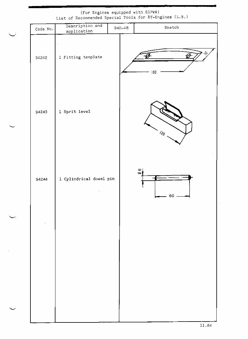
• (For Engines equipped with SIPWA)
List of R e c o ~ m e n d e d Special Tools for RTEngines (L.B.)
Code No.
94242
94243
94244
Description and
application
1 Fitting template
94048
1 Sprit level
1 Cylindrical dowel pin
180
Sketch
60
11.84

Tool List for R e c o ~ m e n d e d Tools for RT Engines (L.B.)
Description and 94049 SketchCode No. application
94231 1 Device for fitting the
oil scraper ring spring
x = 264 mm (RT58)
x = 304 mm (RT68)
x = 334 mm (RT76)
X = 364 mm (RT84)
1 Pneumatic impact wrench94264
with socket
SW 105 (RT58 & RT84) SW 130 (RT68) SW 130 (RT76) SW 245 (RT84)
(compressed air hose 30m long. see tool No.94215, item 'd')
x = 800 mm
1 Tool kit (complete) for fuel injector nozzle maintenance, c o m p r ~ s i n g :
94280
94280a 1 Wooden case
1 Lapping disc 0 46 x 3694281
94282 1 Cooper grinding pin o 15 x 70
94283 1 Checking disc 0 54
94284 1 Wire brush
94285 1 Case with drills for cleaning of the spray holes
1 Plug gauge for checking the spray holes
94286
94287 1 Tin of lapping powder
94288 1 Surface plate 200 x 300 x 40
6 Dowel pins 0 10 x 28
94287
~ "I 94282
8 94283
12.87

Tool list for Recommended Special Tools for RT Engines (L.B.)
Code No. Description and application 94050 Sketch
94291 1 Valve grinding machine
compl. 1 8 7 0 - - - - ~ ~
94299 1 Grinding device for
grinding off any wear
ridge on the running
surface of the cyl.
liner
X approx. 233 mm (RT58
X = " 257 mm (RT68
X = " 274 mm (RT76
X = " 293 mm (RT84
94300 1 Tool cupboard ~
~
~
~
~
0 ~~
~
~
~
~
.. '.'.
.'.
.
.,
0.: .•:::.;
5.84

Recommended special Tools for RT76 Engines
Code No. Description and
application I 9,*0-51 I Sketch
94316 2 Draw bolts for each
crosshead bearing
2 Draw bolts for each
crank pin bearing
with two each washers
and nuts
(The tool is useful
for the storage and
transportation of con
necting rod bearings)
I /
94336 1 Console for resting
working piston
I---- 640
1984

.I
List of Tools Supplied on Loan Basis for RT Engines (L.B.)
Sketch
.- '><
94174 4 off Thread protectors
for the upper thread of M30 (RTS8)
the tie rods during j·\36 (RT68)
fitting of the cylinder M36 (RT76)
jacket 1148 (RT84) I ~~ ~
X
X
= =
140 mm 165 mm
(RT58) (RT68)
4"'~' _--1'
-~ ", Jl
~ ,~-=-~~' *-1
~ ;><
~ X = 185 mm (RT76) X = 205 mm (RT84)
94177 1 Thread protection for X the lower thread of the tie rods
X = 150 mm (RT58) X = 180 mm (RT68) X = 205 mm (RT76) X = 220 mm (RT84)
"''
94185 1 Leaf spring for screw-ing on the lower tie rod nut
X = 720 mm (RT58) j "X = 815 mm (RT68) L: XX = 760 mm (RT76) ,
X =1025 mm (RT84) ,
I
I'""!"
~
8.84