new reinforcing technique for mitigation of earthquake-induced failure … papers... ·...
TRANSCRIPT

6th International Conference on Earthquake Geotechnical Engineering 1-4 November 2015 Christchurch, New Zealand
New Reinforcing Technique for Mitigation of Earthquake-induced
Failure of Breakwater B. Chaudhary1, H. Hazarika2, N. Monji3, T. Hara4, K. Nishimura5, K. Kasama6 and R. Ishikura7
ABSTRACT Coastal structures are susceptible to damage during earthquake and tsunami. Many coastal
structures (e.g., breakwaters, seawalls, river dikes) failed during past earthquakes and tsunamis. It was found that breakwater failed mainly due to failure of foundation. This paper proposes an effective reinforcing technology for breakwater foundation, which provides resiliency to the breakwater against earthquake so that coastal areas will be protected from such disasters in future. The proposed technique uses sheet piles and gabion mound in the breakwater foundation as a reinforcing measure. In order to determine effectiveness of the proposed technique, series of shaking table test were performed and comparisons were made between conventional and proposed reinforced foundation. It was found that the reinforced foundation performed well in reducing damage of breakwater caused by the earthquakes.
Introduction
Many coastal structures, such as breakwaters, seawalls and river dikes failed by past earthquakes such as the 2004 Indian Ocean Earthquake and 2011 Off the Pacific Coast of Tohoku Earthquake and subsequent tsunamis. The 2004 Indian Ocean Earthquake (Mw = 9.1-9.3) triggered a series of devastating tsunamis with wave height up to 30 meters. Large numbers of coastal structures were damaged. The 2011 Off the Pacific Coast of Tohoku Earthquake (Mw = 9.0) was the most powerful earthquake ever hit Japan. Powerful tsunami waves were generated by the earthquake. However, Japan has many experiences of tsunami disasters (e.g. 1896 Meiji Sanriku tsunami, 1983 Nihon-kai Chubu earthquake tsunami, 1993 Hokkaido Nansei-oki earthquake tsunami), and disaster prevention research work in Japan has been energetically carried out since the 1960 Chilean tsunami attacked coast of Japan; but tsunami, generated by the 2011 Off the Pacific Coast of Tohoku Earthquake was more devastating than previous tsunamis. The tsunami led to great catastrophic losses for structures and population living near coastline by not only inundation but also tsunami-debris. Lots of coastal structures (breakwaters, sea walls, river dikes) were damaged (Hazarika et al. 2012) by the earthquake and subsequent tsunami. 1 Department of Civil Engineering, Kyushu University, Fukuoka, Japan, Email: [email protected] 2 Department of Civil Engineering, Kyushu University, Fukuoka, Japan, Email : [email protected] 3 Department of Civil Engineering, Kyushu University, Fukuoka, Japan, Email : [email protected] 4 Department of Natural Science, Kochi University, Kochi, Japan, Email : [email protected] 5 Department of Civil Engineering, Kyushu University, Fukuoka, Japan, Email : [email protected] 6 Department of Civil Engineering, Kyushu University, Fukuoka, Japan, Email : [email protected] 7Department of Civil Engineering, Kyushu University, Fukuoka, Japan, , Email : [email protected]

Breakwaters are one of the main coastal protection facilities that provide safety to the harbor and coastal plain areas from devastating effects of sea waves, currents and tsunamis. The word deepest (depth-63m) breakwater at Kamaishi port (Iwate Prefecture, Japan), collapsed and failed to block tsunami brought by the 2011 Off the Pacific Coast of Tohoku Earthquake. The port of Kamaishi suffered heavy causalities due to collapse of the breakwater, and the breakwater collapsed mainly due to failure of mound. The failure of the breakwater led to enter the tsunami in the coastal plain areas, and the tsunami created a great devastation. It was found that the main reasons of failure of the breakwater were (MLIT, 2013 and Arikawa et. al, 2012) (i) High water pressure imposed on the breakwater due to tsunami waves (ii) Hydrodynamic pressure due to earthquake that generated a huge horizontal force on the breakwater (iii) Decrease in bearing capacity due to increase in pore water pressure in the foundation (iv) Scouring of mound, toe erosion and joint failure by tsunami waves. Some other breakwaters of Japan such as Hattaro Breakwater in Hachinohe Port, Aomori Prefecture; Ryujin-zaki Breakwater at Miyako Port, Iwate Prefecture and breakwater at Onagawa Port, Miyagi Prefecture were also damaged mainly due to failure of mound. The damage to the mound was more significant than that to the main body of the breakwater during earthquake and tsunami. Since great earthquakes such as Tokai Earthquake and Tonankai-Nankai Earthquake are expected to occur in near future in Japan, and will significantly affect coastal regions. Large-scale tsunamis may be generated by these earthquakes. In order to mitigate the damage from such future earthquakes and tsunamis, it is necessary to take appropriate measures that can protect infrastructures and human lives. Safe performance of breakwater is very important for the protection of coastal life and structures near to coastline. Therefore, it is very important to develop and build earthquake and tsunami resistant breakwaters. After the 2011 Off the Pacific Coast of Tohoku Earthquake, development of reinforcement technique which can provide resiliency to the structures against earthquake and tsunami became top priorities of scientists and researchers. This research proposes a new reinforced foundation for breakwaters using (i) gabion mound (foundation rubbles wrapped in wired mesh) with protective gabion (rubbles with gabions) and (ii) reinforcing them with steel sheet piles in order to reduce the failure of the breakwaters due to compound disasters triggered by earthquake and tsunami.
New Reinforcing Foundation Technique for a Resilient Breakwater As a counter measure, a new reinforcing technology is proposed for foundation of breakwater. In place of rubble mound, gabion mound foundation was used and protective gabion was adopted to cover entire mound as shown in Fig. 1. The gabion mound can protect the mound from scouring effect of tsunami waves and improve bearing capacity of the foundation due to its confinement characteristics. Lateral displacement and subsidence of the breakwater can also be controlled due to these properties. In addition to gabion, two rows of sheet piles were installed in the foundation as shown in Fig. 1. As the sheet piles can behave like cut off walls and thus can reduce seepage flow of water below the foundation during tsunami and reduce uplifting force due to seepage of water. The sheet pile can restrict lateral deformation of the foundation soils due to rigidity characteristics, and can reduce deformation of the foundation. The sheet piles can also reduce scouring of the foundation soils during tsunami (both leading wave and backrush). A series of shaking table tests and numerical analyses were performed to evaluate the effect of the proposed reinforcing technique on performance of the breakwater against earthquake.
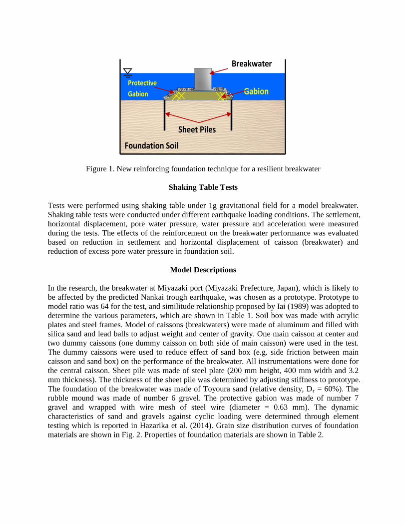
Figure 1. New reinforcing foundation technique for a resilient breakwater
Shaking Table Tests Tests were performed using shaking table under 1g gravitational field for a model breakwater. Shaking table tests were conducted under different earthquake loading conditions. The settlement, horizontal displacement, pore water pressure, water pressure and acceleration were measured during the tests. The effects of the reinforcement on the breakwater performance was evaluated based on reduction in settlement and horizontal displacement of caisson (breakwater) and reduction of excess pore water pressure in foundation soil.
Model Descriptions In the research, the breakwater at Miyazaki port (Miyazaki Prefecture, Japan), which is likely to be affected by the predicted Nankai trough earthquake, was chosen as a prototype. Prototype to model ratio was 64 for the test, and similitude relationship proposed by Iai (1989) was adopted to determine the various parameters, which are shown in Table 1. Soil box was made with acrylic plates and steel frames. Model of caissons (breakwaters) were made of aluminum and filled with silica sand and lead balls to adjust weight and center of gravity. One main caisson at center and two dummy caissons (one dummy caisson on both side of main caisson) were used in the test. The dummy caissons were used to reduce effect of sand box (e.g. side friction between main caisson and sand box) on the performance of the breakwater. All instrumentations were done for the central caisson. Sheet pile was made of steel plate (200 mm height, 400 mm width and 3.2 mm thickness). The thickness of the sheet pile was determined by adjusting stiffness to prototype. The foundation of the breakwater was made of Toyoura sand (relative density, Dr = 60%). The rubble mound was made of number 6 gravel. The protective gabion was made of number 7 gravel and wrapped with wire mesh of steel wire (diameter = 0.63 mm). The dynamic characteristics of sand and gravels against cyclic loading were determined through element testing which is reported in Hazarika et al. (2014). Grain size distribution curves of foundation materials are shown in Fig. 2. Properties of foundation materials are shown in Table 2.
Gabion
Protective Gabion
Sheet Piles
Foundation Soil
Breakwater

Figure 2. Grain size distribution curve of the materials used in the test
Table 1. Similitude for 1G shaking table test
Items Prototype/Model Scale factor Length n 64 Density 1 1 Time n0.75 22.63 Stress n 64 Pore water pressure
n 64
Displacement n1.5 521 Acceleration 1 1 Frequency 1/(n0.75) 0.044 Permeability n0.75 22.63 Bending stiffness n3.5 2097152 Axial stiffness n1.5 521
Table 2. Properties of foundation materials
Properties Toyoura Sand No.6 Gravel No.7 Gravel
Sat. Density, ρs (g/cm3) 2.640 1.620 2.727 Dry Density ρd (g/cm3) 1.506 1.416 1.980 Min. Dry Density (g/cm3) 1.336 1.781 1.768 Max. Dry Density (g/cm3) 1.639 2.773 2.143 Uniformity Coefficient, Uc 1.7 1.5 11.4 Mean Grain Size, D50 (mm) 0.16 4.7 2.7 Plastic Limit, Ip NP NP NP
Experimental Setup
Three different models of breakwater were used in the test as shown in Fig. 3: (i) Conventional breakwater foundation (unreinforced foundation), (ii) Breakwater foundation reinforced with

gabion only and (iii) Breakwater foundation reinforced with combined reinforcement (gabion and two rows of sheet piles together). Instrumentations for shaking table test is shown in Fig. 4, two laser displacement gauges (L-1 and L-2,) and two displacement gauges (D1 and D2) were installed to monitor settlements and horizontal displacements of the caisson respectively. Seven accelerometers (A1 to A7) were used to record accelerations. Four water pressure gauges (W41 to W44) were installed to measure water pressures on the breakwater, and eight pore water pressure gauges (W11 to W33) were installed to monitor pore water pressures in the foundation.
Figure 3. Layouts of the models (i) Unreinforced breakwater foundation, (ii) Breakwater foundation reinforced with gabion only, and (iii) Breakwater foundation reinforced with
combined reinforced (gabion and two rows of sheet piles together)
Figure 4. Instrumentations for the shaking table test
(ii)
(i)
(iii)

Results and Discussions Earthquake loadings in form of sinusoidal waves of frequency 15 Hz with different continuation times (1 second and 8 second) and different accelerations magnitudes (100 Gal, 300 Gal, 400 Gal and 500 Gal) were applied sequentially to the same models. Comparisons were made between unreinforced and reinforced breakwater foundation. Effects of Acceleration Magnitudes of the Earthquake Loadings In order to determine the effect of different magnitudes of accelerations of dynamic loadings on the performance of the breakwater, settlement of the caisson at L1 (top left corner) of the caisson was measured under earthquake loading of different acceleration magnitudes (300 Gal and 500 Gal) and same continuation time (1 second), and is shown in Fig. 5. It can be seen that settlement increases with increase in acceleration magnitude. For 300 Gal, residual settlement of the caisson was 0.9 mm and that increased to 1.0 mm for 500 Gal.
0 1 2 3 4 5-1.2
-1.0
-0.8
-0.6
-0.4
-0.2
0.0
0.2
Settl
emen
t (m
m)
Time (sec)
300 Gal
500Gal
Figure 5. Settlement of caisson for unreinforced foundation at L-1 for different accelerations (300 Gal and 500Gal) and same continuation time (1 second)
The settlement for the foundation reinforced with combined reinforcement measured at L-1 of the caisson under earthquake loading of different acceleration magnitudes (300 Gal and 500 Gal) with same continuation time 1 second, and is shown in Fig. 6. The residual settlement of the caisson increases with increase in acceleration. The settlement was 0.6 mm and 0.8 mm for 300 Gal and 500 Gal respectively. The increase in settlement was found 33% when acceleration increases from 300 Gal to 500 Gal. Effects of Reinforcement The settlements of the caisson at L1 for unreinforced and combined reinforcement foundation are shown in Fig. 5 and 6 respectively. It can be noticed that settlement reduced for reinforced foundation. The settlement of reinforced foundation is 33% and 20% less than unreinforced foundation at 300 Gal and 500 Gal respectively. Probably due to confinement effect of gabion and rigidity characteristics of sheet piles, settlement of the caisson reduced.
0 1 2 3 4 5-1.0
-0.8
-0.6
-0.4
-0.2
0.0
0.2
0.4
Settl
emen
t (m
m)
Time (sec)
300 Gal
500 Gal
Figure 6. Settlement of caisson for combined reinforced foundation at L-1 for different accelerations (300 Gal and 500 Gal) and same continuation time (1 second)
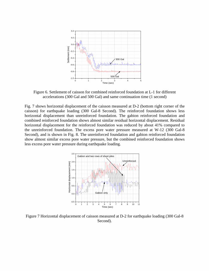
Fig. 7 shows horizontal displacement of the caisson measured at D-2 (bottom right corner of the caisson) for earthquake loading (300 Gal-8 Second). The reinforced foundation shows less horizontal displacement than unreinforced foundation. The gabion reinforced foundation and combined reinforced foundation shows almost similar residual horizontal displacement. Residual horizontal displacement for the reinforced foundation was reduced by about 41% compared to the unreinforced foundation. The excess pore water pressure measured at W-12 (300 Gal-8 Second), and is shown in Fig. 8. The unreinforced foundation and gabion reinforced foundation show almost similar excess pore water pressure, but the combined reinforced foundation shows less excess pore water pressure during earthquake loading.
0 1 2 3 4 5 6 7 8 9 10 11-0.5
0.0
0.5
1.0
1.5
2.0
2.5
Hor
izon
tal d
ispl
acem
ent (
mm
)
Time (sec)
Unreinforced
Gabion and two rows of sheet piles
Gabion only
Figure 7 Horizontal displacement of caisson measured at D-2 for earthquake loading (300 Gal-8 Second).

0 2 4 6 8 10 12 14-0.2
0.0
0.2
0.4
0.6
0.8
1.0
1.2
Exc
ess
Por
e W
ater
Pre
ssur
e (k
Pa)
Time
Unreinforced BW
Gabion Only
Gabion and two rows of sheet piles
Figure 8. Excess pore water pressures in the foundation at W-12 for earthquake loadings (300
Gal-8second)
Numerical Simulation The numerical analyses were performed using finite difference program, FLAC. The purpose of this simulation was to confirm the effectiveness of the proposed reinforcement technique against earthquake loadings and to make clear the mechanism. The sea bed was modelled as cohesionless material with elastic plastic response with Mohr-Coulomb failure criterion. For liquefaction behaviour of sea bed, the formula proposed by Byrne (1991) was used in the analysis. The breakwater was modelled as elastic material. Fixed boundary conditions were applied at both end sides of the model during the dynamic loadings. The numerical model was made similar to that of shaking table test. A damping ratio of 5% was assigned to the model. Dynamic loading in the form of sinusoidal waves of acceleration 400 Gal, time 8 second and frequency 15Hz were applied to the model. The numerical model of unreinforced breakwater foundation is shown in Fig. 9. The shear strain distribution for unreinforced breakwater foundation at the end of dynamic loading is shown in Fig. 10. It can be seen that strain below the left and right corner of the caisson is high. The soil below the left and right corner of the mound is highly deformed. This is due to tilting of the caisson which was noticed during the shaking table tests also.
Figure 9. Numerical model of unreinforced breakwater

Figure 10. Shear strain distribution within the mound and the foundation soils In order to evaluate the effect of width (b) of the caisson, settlement and horizontal displacement of the caisson were measured for different width (b = 0.75H, 1.0H and 1.5H, where H= height of the caisson) of the caisson. The settlement of the caisson measured at top right corner of the caisson, and is shown in Fig. 11. It can be seen that settlement increases with decrease in width of the caisson. The horizontal displacement of the caisson measured at bottom right corner of the caisson, and is shown in Fig. 12 for unreinforced foundation. It can be observed that the horizontal displacement is almost similar for b = 1.50H and 1.00H (H = height of the breakwater) but for b = 0.75H, the horizontal displacement is more than other cases.
0 2 4 6 8-25
-20
-15
-10
-5
0
5
b = 0.75H
b = 1.0H
Settl
emen
t (m
m)
Time (Second)
b = 1.5H
Figure 11. Settlement of the caisson for different width of the caisson
0 2 4 6 8-6
-5
-4
-3
-2
-1
0
1
b = 1.00H
b = 1.50H
Disp
lace
men
(mm
)
Time (Second)
b = 0.75H
Figure 12. Horizontal displacement of the caisson for different width of the caisson

Conclusions
This paper proposed a new reinforcement technique for foundation of breakwater, which provides resiliency to the breakwater against earthquake. To evaluate the effectiveness of the proposed reinforcing technique, a series of shaking table tests and numerical analyses were performed. The reinforced breakwater foundation performed well in reducing settlement as well as horizontal displacement of the caisson during earthquake loadings and thus reducing damage of breakwater mound due to earthquakes. Sheet piles can restrict the lateral flow, and thus could reduce the differential settlement. It can be said that the proposed reinforcing technique provides better mitigation effect as the vertical settlement, horizontal displacement of caisson as well as excess pore water pressure in the foundation could be reduced significantly.
Acknowledgement
This study was funded by the Japan Iron and Steel Federation under priority themes research grant. The authors express their deep gratitude for this financial support.
References Arikawa, T, Sato, M, Shimosako, K, Hasegawa, I, Yoem, G S and Tomita, T. Failure mechanism of Kamaishi breakwater due to the great east Japan earthquake tsunami. Proceedings of 33rd Conference on Coastal Engineering Santander Spain 2012; 1-13.
Byrne, P. A cyclic shear-volume coupling and pore-pressure model for sand. Proceedings of 2nd International Conference on Recent Advances in Geotechnical Earthquake Engineering and Soil Dynamics St. Louis Missouri 1991; 1(24): 47-55.
Central Disaster Mitigation Council. Report of the 16th Committee Meeting. Investigation Committee on Tonankai Earthquake and Nankai Earthquake. Cabinet Office Government of Japan 2003 (in Japanese).
Hazarika, H, Chaudhary, B, Monji, N, Ishikura, R, Kasama, K, Hara, T, Yamasaki, N, Noda, T and Yamada, S. Resilient breakwater foundation against level II earthquake and tsunami. Proceedings of the 6th International Geotechnical Symposium on Disaster mitigation in Special Geoenvironmemt Conditions Chennai, India 2014; 35-46.
Hazarika, H, Kataoka, S, Kasama, K, Kaneko, K, and Suetsugu, D. Compound ground disasters caused by the earthquake and tsunami in Aomori, northern Iwate Prefecture. Geotechnical Engineering Journal, Special Issue on 2011 Great East Japan Earthquake 2012; 7(1): 13-23 (in Japanese).
Iai, S. Similitude for shaking table tests on soil-structure-fluid model in 1g gravitational field. Soils and Foundations 1889; 29(1): 105-118.
MLIT. Guidelines for earthquake resistant design of breakwaters. Reference Materials, Ministry of Land, Infrastructure, Transport and Tourism, Government of Japan 2013. (in Japanese).