new possibilities for quality assurance of diaphragm …€¦ · new possibilities for quality...
TRANSCRIPT

NEW POSSIBILITIES FOR QUALITY ASSURANCE OF DIAPHRAGM WALL JOINTS
Ernst Niederleithinger, BAM Federal Institute for Materials Research and Testing, Berlin, Germany, +49 30 81041443, [email protected]
Joram M. Amir, Piletest.com Ltd., 85 Hanassi Street, Herzlia 46399, Israel, +972- 9957 8992, [email protected]
Nikolaus Schneider, GuD Geotechnik und Dynamik Consult GmbH, Dudenstr. 78, 10965 Berlin, Germany, +49 30 789089-0, [email protected]
Abstract: Diaphragm walls are used to provide a stable and watertight confinement for the construction of tunnels, underground railway stations, deep basements and other structures requiring deep excavations. Water seepage and soil loss through the joints have occurred on several occasions, causing extensive damage. This may have been due to uncontrolled concrete flow between the joints, unexpected geologic conditions or just poor workmanship.
Different ways of quality assurance are applied on construction sites. Most of them rely on recording parameters of the construction equipment and conventional concrete quality control. In the frame of the EUREKA/ZIM project DiWaQ we have looked at several ways to perform non-destructive quality control. Some methods are to be applied after excavation before concreting (phase 1); others after the wall is completed (phase 2).
For phase 1 we have used two different principles for checking the shape of the excavation, especially the joint to existing panels. A mechanical device which can be adapted to the excavating equipment was developed; field tested and validated on test and construction sites. It is described in detail in another paper in the same volume. A sonar-based device with a 10 mm resolution has shown good performance in the lab, but is still under development.
For phase 2 different temperature sensors have been lowered into access holes to monitor the hydration heat developed during concrete curing. The same tubes can also be used to perform electromagnetic and ultrasonic crosshole measurements across or along joints to detect flaws. Especially the ultrasonic method has shown promising results on validation specimen at the BAM test site at Horstwalde, but limitations as well. Success substantially depended on the joint type, flaw size and distance of the sensors to the joint.
Introduction
Diaphragm walls are used all around the world to provide a stable and watertight confinement for the construction of tunnels, underground railway stations, deep basements and other structures requiring deep excavations. These walls consist of individual panels, cast piece-wise in the ground, separated by watertight joints. There are several methods to improve the water tightness of these joints, including rubber bands, metal sheets or precast concrete elements. As diaphragm walls are reaching depths of up to 60 m, they have to withstand large earth and water pressures.
In most cases the performance of diaphragm walls is fully satisfactory. However, quality problems may result in a mixture of water and soil particles flowing through the joints into the excavation. This will lead to a lack of performance (especially water inflow) or to the failure of a single panel, the entire wall or even adjacent buildings. A recent accident in Germany (e.g. Sieler et al., 2012) has cost two lives and immeasurable damage to cultural heritage. A similar failure was also experienced in Amsterdam. These quality problems may have been due to uncontrolled concrete flow between the joints, unexpected geologic conditions or poor workmanship.
911

Different ways of quality control (QC) are applied on construction sites. As the bentonite slurry used for stabilization prevents direct visual inspection, Q|C is mainly limited to check the slurry itself and to record operating data by the machinery used, including verticality of the slurry trench (Amir and Amir, 2012). For a more detailed inspection, two commercially available types of sonar instruments (“Koden instrument”, “Sonic Caliper”) developed mainly to check the shape of boreholes for drilled shafts can be used in excavated, bentonite filled trenches to examine the geometry of the barrette (e. g. Chan & Tsang, 2004; Kort & Hayes, 2007; Schneider, 2014). However, both instruments require highly skilled technicians. Applications to diaphragm walls have been reported in personal communications and brochures, but haven’t been published yet.
Several methods have been proposed for QC in the stage between concreting and excavation. This includes thermal (Doornenbal et al., 2011) and ultrasonic methods (Spruit et al., 2011). Both methods have so far been applied experimentally, the latter one as well on a construction site in the Netherlands (Spruit et al., 2013). The length of existing diaphragm walls can be determined by the parallel seismic technique (Niederleithinger, 2012).
From 2011 to 2013 a project on quality assurance of diaphragm walls (DiWaQ) had been implemented in cooperation between two companies from Israel and Germany and BAM to develop and improve prototype instrumentation. Both pre- and post-concreting measurements have been included. For phase 1 (measurements in an excavated panel before concreting, Figure 1), the focus has been on a mechanical device which can be mounted on the excavation equipment, but alternatives have been considered as well. Phase 2 is aimed to localize flaws in the joints after concreting (Figure 2). The first stage will allow corrections in the construction process, while the second one will serve as a final check after completion of the wall.
Figure 1: Phase 1 of diaphragm wall joint inspection after excavation (by sonar or other sensors). Top view.
Figure 2: Phase 2 of diaphragm wall joint inspection (after concreting, by ultrasonic or other sensors). Top view.
Phase 1 (measurements in an excavated panel)
If obstacles, excess concrete or any other issues at the joints could be located in the exposed panel before concreting the adjacent one, remediation measures could be applied immediately to avoid problems after completion of the wall. As the visibility in the suspension is zero, indirect inspections methods have to be used. In DiWaQ we have followed two approaches. The focus has been on a mechanical device, which is mounted on the excavation grab and while being pulled upwards records the shape of the joint using tactile levers. This device, named the GuD Joint Inspector, is presented in detail in another paper in the same volume (Schneider, 2014).
912

As an alternative we have developed a prototype sonar device, which has the same basic principle as the instruments mentioned earlier, but will be much lighter, cheaper and easier to use. The new device is based on a standard dual beam marine sonar sensor with a central frequency of 120 kHz. The signal generation and triggering units are in-house developments of BAM, while the remaining components as a power amplifier or a digital data acquisition device are industry standard. The details of the device and the lab experiments carried out are given in detail in Niederleithinger & Garcia, 2014. The setup of the lab experiments, which have been carried up to bentonite slurry density of just 1.06 g/cm³ due to limitations of our mixing apparatus, is shown in Figure 3 and Figure 4. Obstacles of various size, material and distance to the pool’s wall have been mounted on one end. The sonar sensor was moved vertically at various distances from the obstacle.
Figure 3: Sonar and obstacles in the lab test pool.
Figure 4: Test pool with sonar inserted.
Figure 5 shows the results of sonar measurements in case of a steel obstacle with a vertical size of 200 mm, centered at 500 mm height above the pool bottom. The sonar sensor has been moved vertically in 20 mm intervals. All signal traces show the transmitted signal at 250 µs delay set by the data acquisition device. The echo of the backwall is seen at about 800 µs, referring to a wave speed of around 1450 m/s. The obstacle position is shown by echoes at an earlier time (about 600 µs, sensor height 40 – 60 cm). Data in Figure 6 refer to a much smaller obstacle (vertical size 50 mm) made of Plexiglas. The obstacle effect is still clearly visible, but upper and lower boundaries are not as well delineated as for the larger object. Note, that both results show much weaker backwall echoes above the obstacle, probably due to air introduced into the suspension when inserting the obstacles. Other experiments have shown that the accuracy of distance measurements is 20 mm or better. Advanced data processing methods, e.g. deconvolution, have shown to be beneficial for accuracy (Niederleithinger & Garcia, 2014).
913

Figure 5: Sonar test result with steel obstacle (vertical size 200 mm).
Figure 6: Sonar test result with Plexiglas obstacle (vertical size 50 mm).
Phase 2 (measurements across joints after concreting)
To evaluate the capabilities of various sensors to perform cross-hole examination of joints in diaphragm walls after concreting two test models have been constructed at the BAM test site in Horstwalde. Both models have a size of approximately 2*2*0.6 m³ and have been cast in two parts to include a joint and two artificial flaws therein. Six sensor access tubes (PVC, 50 mm diameter) have been attached to the reinforcement. The joint is semicircular for model 1 (Figure 7), as if tube type stop ends would have been used. Model 2 (not shown) contains a steel sheet between panels. Flaws have a vertical size of 300 mm, span half or full width of the joint. The flaw covering the full width is made of high porosity foam, covered by a thin plastic sheet to avoid concrete flowing in. (Figure 7). The smaller flaw is filled with clay.
We have planned to test various sensors at our models. So far we collected data with temperature and ultrasonic devices. An additional microwave sensor is still under development.
Directly after concreting the second half of each model we have deployed an infrared sensor developed by Piletest.com to the access tubes both in the newly cast and in the already cured half of the model (Figure 8, left). We had expected that measurements in the new part would show the hydration temperature in the model. The thermal energy should also heat the older part of the model up to a certain extent, except, where conduction is inhibited by flaws in the joint. The sensor itself worked perfectly, but the data from the older part of the model did not show the expected effect (anomalies caused by flaws). Probably several issues contributed to this outcome: the model size is limited (boundary effects), the cement chosen produced a comparably small temperature anomaly (just 1°C after 24 h) and the point of measurement (access tube) was too far from the joint.
914
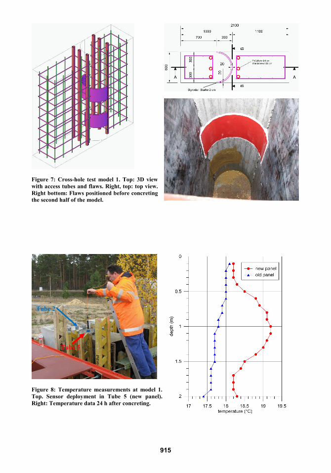
Figure 7: Cross-hole test model 1. Top: 3D view with access tubes and flaws. Right, top: top view. Right bottom: Flaws positioned before concreting the second half of the model.
Figure 8: Temperature measurements at model 1. Top. Sensor deployment in Tube 5 (new panel). Right: Temperature data 24 h after concreting.
Tube 2
Tube 5
915

After at least 7 days of curing the joints can be inspected by the ultrasonic cross-hole method, which is regularly applied on drilled shafts, but also inside diaphragm wall panels (e.g. Mendez, 2012; Schneider, 2014). Transmitter and receiver have been placed on opposite sides of the joint (Figure 9) at the bottom of the access tubes and the raised in parallel. This configuration has also been used for diaphragm walls by Spruit et al (2011) on a model and by Spruit et al. (2014) on a construction site as well as for pile secant walls by (Niederleithinger et al., 2010) on a model and by (Niederleithinger et al., 2012) at a construction site. Figure 10 shows the results obtained at model 1 for all three adjacent tube pairs. Data are displayed as waterfall records (timeseries amplitudes translated into a black/green/white color code and plotted at sensor depth). Travel time and amplitude have been extracted and are shown to the left of the raw data.
The large artificial defect is clearly visible around 1 m depth. The smaller defect can be seen as well, but only at the leftmost dataset and with a much smaller effect. This is caused not just by the size, but also by the material used for the flaw, clay having a smaller contrast to concrete compared to air/water/plastic in the larger flaw. It can be seen, that in the topmost 1 m the amplitudes are weaker in general, probably cause by a thin delamination in the joint. We have tried to fill this small space with water by sealing the joint on both sides and having a constant level of water on the top of the model. But this measure has not been fully successful. A similar effect can be seen in the field data of Spruit et al. (2013) above the ground water level. The measurements on model 2 have been less conclusive, probably due to the steel sheet in the joint, allowing much less energy to be transmitted.
Figure 9: Ultrasonic cross-hole measurements at model 2.
916

Figure 10: Ultrasonic cross-hole results for model 1, each measured with transmitter/receiver in tubes opposite across the joint.
Summary and conclusions
Various methods for quality assurance of diaphragm walls (mainly their joints) have been developed, improved and/or tested in the frame of the project DiWaQ. We have split the task into two phases, one after excavation before concreting, the second after concreting.
For phase one, a mechanical device (“GuD Joint Inspector”) has been developed, which is described by Schneider (2014). The device is ready for commercial use. A sonar system developed by BAM has shown promising results in the lab and a resolution of at least 5 cm in vertical obstacle size and 2 cm in distance measurements, but needs further development before practical use. Both methods aim at the inspection of the stop end of previously casted panels by lowering sensors into the bentonite suspension filled slot of the adjacent panel. Both methods should work independent of the joint type used.
Phase two aims at the inspection of the joint by sensors lowered into access tubes, which have been installed at the reinforcement cages. While microwave sensors are still in the very early development stage, temperature sensors are ready to use. Our trials at a scale model have been only partially successful for several reasons (e.g. limited size of model, inappropriate distance of sensor to joint). However, we imagine this method to be of practical use in the future. Experiments with ultrasonic logging (transmitter and receiver on opposite sides of the joint) have been far more successful. We were able to locate an artificial flaw (height 30 cm, width covering full joint) accurately. Some issues remain, as the method might not work above groundwater level, at certain joint systems or to locate small flaws. However, if local conditions are favorable, this methods can be recommended for practical use (confirmed e.g. by Spruit et al, 2013).
To conclude, we favor the use of phase one methods so far, as they are less dependent on local conditions and joint types, and allow for rehabilitation measures before concreting. The ultrasonic crosshole method is valuable as well, as it allows a final inspection before excavation.
large flaw
small flaw
917

Acknowledgements
The German partners would like to acknowledge the funding available via the EUREKA 6286/ZIM-KF2201031RR1 project DiWaQ. We deeply appreciate the help of numerous colleagues at BAM, Piletest and GuD in preparing and performing the experiments.
References
Amir, J.M. and Amir, E.I. (2012): Testing of Bored Pile Inclination. Proceedings of the 9th International Conference on Testing and Design Methods for Deep Foundations (IS-Kanazawa 2012).
Chan, F. W. Y., and Tsang, S. W. F. (2004): Earth Echo Sounding Technique for Quality Control of Drilled Shafts Foundations. Insight 46(4): 17–22.
Doornenbal, P., Hopman, V., and Spruit, R. (2011): High Resolution Monitoring of Temperature in Diaphragm Wall Concrete. Proceedings of Field Measurements in Geomechanics. Berlin.
Kort, D. A., and Hayes, J. S., (2007): Sonar Calipering of Slurry Constructed Drilled Shafts – Providing Quality Assurance and Quality Control in Deep Foundations.” In Proceedings of the 32nd Annual Conference on Deep Foundations, Colorado Springs: Deep Foundations Institute.
Mendez, J. A., Rausche, F., and Paulin, J. (2012): “Quality Control of Diaphragm Walls by Crosshole Sonic Logging.” In Full-Scale Testing and Foundation Design: Honoring Bengt H. Fellenius, Geocongress 2012, p. 650–663.
Niederleithinger, E., Hübner, M. and Amir, J.M. (2010): Crosshole Sonic Logging Of Secant Pile Walls - a Feasibility Study. Symposium On The Application Of Geophysics To Environmental And Engineering Problems (SAGEEP), Keystone, Co.
Niederleithinger, E., Hübner, M., Müller, H., and Kauther, R. (2012): “Qualitätssicherung Überschnittener Bohrpfahlwände mit der Ultraschallmethode am Beispiel der Schleuse Dörverden.” In Fachtagung Bauwerksdiagnose 2012. Berlin. http://www.bauwerksdiagnose2012.de/Portals/bwd2012/Dokumente/bb/v17.pdf.
Niederleithinger, E. (2012): Improvement and Extension of the Parallel Seismic Method for Foundation Depth Measurement. Soils & Foundation 52: 1093–1101.
Niederleithinger, E., and Ranz Garcia, J (2014) “Quality Assurance of Diaphragm Walls by Sonar Measurements – Model Study.” Geotechnical Engineering, accepted for publication, available online: http://www.icevirtuallibrary.com/content/article/10.1680/geng.13.00038.
Robinson, E., Treitel., S. (1980): Geophysical Signal Analysis. Prentice Hall. Schneider, N. (2014): A New Method of Quality Control for Construction Joints in diaphragm Walls.
Same Volume. Sieler, Ulrich, Rolf Pabst, Gerd Neweling, and Christian Moormann (2012): “Der Einsturz des
Stadtarchivs in Köln. Bauliche Maßnahmen zur Bergung der Archivalien und zur Erkundung der Schadensursache. Proceedings of 32. Baugrundtagung, 26.–29.9.2012 in Mainz.
Spruit, R., Hopman, V., van Tol, F., and Broere, W. (2011) Detecting Defects in Diaphragm Walls Prior to Excavation. Proceedings of Field Measurements in Geomechanics, Berlin.
Spruit, R., van Tol, F., Broere, W., Slob, E., and Niederleithinger, E. (2014): Detection of anomalies in diaphragm walls with cross-hole sonic logging. Geotechnique, accepted for publication.
918