new mexico department of transportationdot.state.nm.us/content/dam/nmdot/transit_rail... · this...
TRANSCRIPT
R A I L
NEW MEXICO DEPARTMENT OF TRANSPORTATION
NEW MEXICO SECTION 130 FEDERAL AID HIGHWAY-RAIL GRADE CROSSING SAFETY IMPROVEMENT PROGRAM
PROCEDURES AND GUIDELINES MANUAL
NMDOT RAIL BUREAU DECEMBER 2014
This New Mexico Department of Transportation (NMDOT) Section 130 Highway
Rail Grade Crossing Safety Improvement Program "Procedures and Guidelines"
Manual is approved as to form and sufficiency by the NMDOT Cabinet Secretary
or Designee:
By: (jt_
Tom Church, Cabinet Secretary or Designee
Date: /'2/;o 2014
Page 2 of 15
TABLE OF CONTENTS
Introduction 3 The Section 130 Program Process 3 General Process Annual Timeline 5 Crossing Selection 5 Corridor Projects 5 Review Process 6 Safety Improvement Categories 7 Non-Eligible Items 9 Project Construction 10 Recommended Minimum Installation Guidelines 11 Exhibit A-1 Regulatory Signs Exhibit A-2 Advanced Warning Signs Exhibit A-3 Crossbuck Assembly Sample Exhibit B-1 Roadway Pavement Striping/Sign Placement Exhibit B-2 Roadway Pavement Striping Detail Exhibit B-3 Shared-Use Pathway Striping/Sign Placement Exhibit C Crossing Layout and Cross Section Exhibit D Crossing Diagnostic Evaluation Form
Page 3 of 15
Introduction The New Mexico Section 130 Highway-Rail Safety Improvement Program (“Section 130 Program”) is a federally-funded program dedicated to the elimination of hazards at existing highway–rail grade crossings (“Crossings”). The Section 130 Program is authorized by Title 23, United States Code, Section 130 (23 U.S.C 130) and is administered by the New Mexico Department of Transportation (NMDOT) Rail Bureau. The purpose of the Section 130 Program is to reduce hazards to motorists, bicyclists, and pedestrians at Crossings. The Section 130 Program is a cooperative effort between the Federal Highway Administration (FHWA), Federal Railroad Administration (FRA), NMDOT, and railroad companies operating within the State of New Mexico, and local municipalities or counties. Program Contact Information: Primary: Angie Lujan, Section 130 Program Coordinator [email protected] (505) 629-3617 Secondary: Rob Fine, Rail Facilities Manager [email protected] (505) 827-5133 Bill Craven, Rail Bureau Manager [email protected] (505) 827-5263 The Section 130 Program Process Railroad grade crossings from around the State are identified for potential safety improvement projects through the NMDOT Rail Bureau with the assistance of the Federal Railroad Administration risk index data and as well as information, concerns, and requests received from railroads, NMDOT Districts, local county and municipality agencies (“Local Agencies”) and citizens.
Page 4 of 15
An initial identification of potential projects is accomplished by utilizing available data sources to identify crossings that present a high hazard potential. Items evaluated include but are not limited to: Accident history Train volume and speed (including passenger trains) Vehicle volume and speed Physical conditions of crossing Passive or Active Warning School bus routes Pedestrian issues Bicycle issues Crossing geometry (including relation to roadway intersections and traffic signals)
Using this information, Rail Bureau staff reviews each identified crossing to determine eligibility and priorities of which should be considered for a Section 130 project. Factors considered include federal program requirements, eligibility criteria (verification if crossing is public or private), funding availability, and if suggested improvements can be covered under the scope of the Section 130 Program. Field inspections of the crossings may be warranted to assist in this determination. Potential projects are then prioritized based upon accident history, school bus, pedestrian and hazardous materials/truck routes, FRA accident prediction rankings, and physical crossing conditions. Once a list of potential Section 130 projects has been assembled, a Section 130 project selection committee meeting is coordinated and scheduled by the Rail Bureau in order to review potential projects and concur on recommendations. Selection committee meetings generally occur once per year, but may be delayed when there are a large number of projects from previous years awaiting authorization. The committee generally includes participants from NMDOT, Federal Railroad Administration, New Mexico Public Regulation Commission, Federal Highway Administration, and each railroad in the state. The resulting list of recommended projects is then forwarded to the NMDOT Cabinet Secretary for final approval. Once approved, NMDOT Rail Bureau Staff proceeds to enter the projects into the State Transportation Improvement Program (STIP) in order to reserve funding for the projects. Next, Rail Bureau staff coordinates with railroads, NMDOT districts and local agencies to conduct a detailed field diagnostic review for each selected project. Participants of each diagnostic review discuss suggested safety improvements and issues and concur on the scope of the project. Cost estimates are then requested by the NMDOT Rail Bureau from the respective railroad owner or operator in order to prepare contracts that are then executed with the railroads. The contracts will describe the scope of the project and will direct the railroad to perform construction of the improvements. Upon completion of the project, Rail Bureau staff will conduct a field inspection to verify that the project was completed satisfactorily to scope.

Page 5 of 15
General Process Annual Timeline Month Process August Submit a Call for Projects to railroads, Districts, Communities for Following
Year’s Program October-January Review Submittals, Identify Potential Candidates February-March Hold Project Selection Meeting; Submit Final Project List to Cabinet
Secretary for Program Approval; Reserve Funding in upcoming Federal Fiscal Year STIP
March-June Conduct Diagnostic Reviews and Request Formal Railroad Estimates July Prepare and Execute Contracts, Issue Authorization to Proceed Letters for
upcoming Federal Fiscal Year beginning October 1 October New Federal Fiscal Year Begins. Projects begin once authorized. Crossing Selection Not all crossings are eligible for funding under the Section 130 Program. Types of grade crossings must be owned and/or maintained by a public authority. Crossings that are not eligible include: Construction of New Crossings Private Crossings Crossings used only by Light Rail Vehicles Crossings for Station Platforms Quiet Zone Applications by local public agencies (defined in 49 CFR Part 222) Demonstration or Pilot Projects Grade-Separation projects, while eligible for Section 130 Program funding, are also not considered under Section 130 due to the magnitude of costs of such projects. Grade Separation projects instead can be considered under the Highway Safety Improvement Program (HSIP), a federal funding program that is separate of the Section 130 Program. Corridor Projects A Corridor Project is comprised of two or more crossings that are located in close proximity to one another or within a single city or county jurisdiction. These projects are usually established to address a specific improvement at multiple crossings without necessarily addressing all identified hazards at each individual location. This may be due to a change in standards such as MUTCD standards or a specific identified improvement best addressed at once over a number
Page 6 of 15
of locations to encourage efficiency and lower project costs such as signal circuitry upgrades or replacing older incandescent flashing lights with updated Light-Emitting-Diodes (LED) lamps. Corridor Projects are typically requested by a local agency or railroad. While not required, a significant financial contribution or match provided by a railroad or local agency can often help to facilitate a Corridor Project. Review Process Rail Bureau staff reviews each Section 130 project request submittal to determine if it is eligible for funding. Next, the staff considers the current conditions of the crossing and the characteristics of the area it serves, (such as type of development or current development plans and use of the crossing by pedestrians, school buses, hazmat and other heavy truck/bus traffic), Federal Railroad Administration Accident Prediction Formula rankings, train volume and speeds, vehicle counts and speeds, accident history, crossing geometry, and existing warning devices. This evaluation may include field visits as necessary. Crossings are ranked on hazard potential and most immediate needs. Submittals are further narrowed down to a list of priority projects base upon anticipated funding presented at the Section 130 Evaluation meeting. The evaluation committee, made up of representatives from NMDOT, railroads, Federal Railroad Administration, Federal Highway Administration, and the New Mexico Public Regulation Commission, concur on what crossings to proceed on as projects, delay, or to not consider further. A final project list is developed based upon the results of the evaluation meeting. The projects are then submitted to the NMDOT Cabinet Secretary as recommendations for approval. Approved projects are then programmed into the STIP in order to reserve funding. The Rail Bureau schedules diagnostic field reviews of each approved project with the respective railroad, NMDOT District staff and other local road authority agencies. Crossing issues are identified in the field and diagnostic attendees concur on the improvements to be included. The Rail Bureau then develops a scope of work and requests project estimates from the respective railroads based upon the improvements identified at the diagnostic reviews. Using these formal estimates, contract agreements are prepared and executed. Separate agreements may be executed for design and construction for more complex projects. Once funds are obligated through the Federal Highway Administration, railroads are provided “Authorization to Proceed” letters in order to begin work.

Page 7 of 15
Safety Improvement Categories Crossing Elimination Railroad Track Abandonment: Railroad track abandonment occurs when railroad operations ceases on a particular segment of track that a railroad company deems as no longer needed. The tracks are typically then removed. Section 130 funds are not available solely for the removal of grade crossings on previously abandoned tracks unless it is a part of a Section 130 project to improve the safety of an adjacent active track crossing. The removal of an entirely abandoned crossing is the responsibility of coordination between the track owner and the road authority. Closure: Closing and removing a railroad crossing can occur as an option to completely remove a point of conflict between vehicular traffic and trains. This includes removal of the warning devices, crossing surface and approaches, and construction of barriers or fencing and addition of signage as determined necessary in order to indicate the crossing no longer exists. Section 130 funding is available as a match to a railroad incentive payment provided to the road owner or local agency to close the crossing. Railroad Improvements Warning Devices: The Section 130 Program will fund the upgrade of warning devices, such as replacing lone flashing lights with a combination of flashing lights and gates or cantilevers, or adding additional lights on existing masts or cantilevers. LED flashing lights: LED lights will be included on all new warning device installations. In cases where the warning devices do not need to be replaced, the older incandescent flashing lights may upgraded to new LED flashing lights. Track Circuitry: Train detection circuitry embedded in the track or other signal circuitry may be upgraded where deemed necessary to increase effectiveness and reliability of the warning system. Interconnection: Traffic signal preemption may be installed or modified where deemed necessary in locations where grade crossings are adjacent to traffic signalized road intersections.
Page 8 of 15
Road Improvements Active Advanced Warning: A train-activated warning device placed in advance of the crossing. This may be a flashing yellow light located at the passive advanced warning sign. The type of active advance warning device shall be determined at the field diagnostic meeting. Medians: Installation of medians will reduce the ability of a motor vehicle to drive around lowered crossing gates and may encourage vehicles to also slow down while approaching crossings. The type, width and length may vary due to specific field conditions. Illumination: Installation of street lights can provide additional visibility of the crossing at night. Signage and Striping: Signage and striping can be installed to meet current Manual on Uniform Traffic Control Devices (MUTCD) standards or other state or federal regulations, and also provide for site-specific conditions. Road Geometry Improvements: Reconstruction or paving of road approaches to the crossing. Traffic Control Signals: Railroad crossings are commonly adjacent to road intersections. Traffic control signals may be added to adjacent intersections or altering existing traffic signal designs can be accomplished where warranted. Utility Relocation: Utilities, such as overhead wirelines, may need to be adjusted or relocated to provide clearance for warning devices at the crossing.
Page 9 of 15
Pedestrian Crossing Improvements Improvements may include detectable warning strips, pedestrian flasher lights, pedestrian gates, channelization, swing gates, crossing surface improvements and signage and striping. Improvements shall comply with the Americans with Disabilities (ADA) Act. Preliminary Engineering Preliminary Engineering for railroad crossing improvements can be funded through the Section 130 Program under a Preliminary Engineering agreement that would cover the work necessary to produce construction plans, specifications, and estimates to the degree of completeness required for undertaking construction thereunder, including identifying crossings, field diagnostic reviews and locating utilities, surveying, designing, and other related work. Other items: Certain case-by-case situations may require additional applications due to specific field conditions, such as de-acceleration or acceleration lanes, four quadrant gates and removal of site-distance obstructions where possible. Non-Eligible Items under Section 130 A local road authority may wish to implement additional improvements at their own expense at the same time as Section 130 work is being conducted in order to potentially reduce highway traffic control costs and railroad flagging protection costs. Such construction work shall be coordinated between the railroad and local road authority. Improvements that are not specifically included in the recommendations for the Section 130 portion of the project are not funded by the Section 130 Program. In addition, Section 130 funding cannot be used for the following items: Station crossings Construction of new crossings Widening of a roadway for capacity improvements Purchase of right-of-way or easements Costs incurred by the railroad or public road authority prior to execution of a project
agreement with NMDOT (these costs cannot be reimbursed by NMDOT). Environmental studies Significant geometric changes such as relocation or realignment of roadway or railroad
track. Railroad crossing maintenance costs†. Structures providing grade separation of road from railroad ‡.

Page 10 of 15
† Section 130 funds will not be used for routine maintenance costs for crossing surfaces, approaches or flashing lights and gates. The railroad is typically responsible for maintaining the crossing surface between the rails and within two feet from outside of the rails, crossbuck assembly signage and flashing lights and gates. Beyond this, the road owner is typically responsible for maintaining the road surface, pavement markings and striping and advanced warning signage.
‡ While technically eligible for Section 130 funding, grade separation requests cannot be accommodated under the Section 130 Program due to the large magnitude of costs for a single project. Grade Separation requests will be referred to the HSIP selection committee for their consideration.
Project Construction Once a project has been recommended by Rail Bureau staff and approved by the NMDOT Cabinet Secretary, the project will be programmed under the State Transportation Improvement Program (STIP) to reserve funding for the project. The railroad or local road authority will provide a cost estimate for the project and NMDOT will enter into a formal agreement with the railroad or local road agency in order to perform construction. Separate agreements may be executed for design and construction for more complex projects. Rail Bureau staff will obtain federal certifications required for project construction and submit the agreement and certifications to the Federal Highway Administration for project authorization. Once the project is granted authorization, Rail Bureau staff will issue a formal “Authorization to Proceed” letter to the railroad or local road agency to begin construction. Rail Bureau staff will perform one or more inspections to ensure the construction work has been satisfactorily completed. A railroad or local agency should complete construction work and invoicing in a timely manner in order to prevent the project from entering an ‘inactive’ status. Proper and complete invoices may be submitted to NMDOT on a progressive basis for reimbursement as costs are incurred during the course of the project. Projects that have seen no activity over time and become inactive are susceptible to the remaining federal fund being pulled from the project by FHWA. In such an event the railroad or local agency would be responsible for any costs incurred but not reimbursed at the time when funding is pulled by FHWA. A Section 130 project is not deemed fully complete until the NMDOT formally closes out the project through FHWA. A project cannot be closed until NMDOT conducts a final and satisfactory field inspection of the project and all project invoices have been properly submitted by the railroad or local agency and paid by NMDOT. It should be noted that for a railroad or public agency to be fully reimbursed for project costs under a Section 130 agreement, all remaining invoices should be submitted to NMDOT within a certain time frame after the
Page 11 of 15
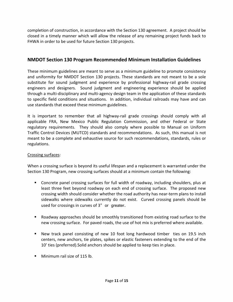
completion of construction, in accordance with the Section 130 agreement. A project should be closed in a timely manner which will allow the release of any remaining project funds back to FHWA in order to be used for future Section 130 projects. NMDOT Section 130 Program Recommended Minimum Installation Guidelines These minimum guidelines are meant to serve as a minimum guideline to promote consistency and uniformity for NMDOT Section 130 projects. These standards are not meant to be a sole substitute for sound judgment and experience by professional highway-rail grade crossing engineers and designers. Sound judgment and engineering experience should be applied through a multi-disciplinary and multi-agency design team in the application of these standards to specific field conditions and situations. In addition, individual railroads may have and can use standards that exceed these minimum guidelines. It is important to remember that all highway-rail grade crossings should comply with all applicable FRA, New Mexico Public Regulation Commission, and other Federal or State regulatory requirements. They should also comply where possible to Manual on Uniform Traffic Control Devices (MUTCD) standards and recommendations. As such, this manual is not meant to be a complete and exhaustive source for such recommendations, standards, rules or regulations. Crossing surfaces: When a crossing surface is beyond its useful lifespan and a replacement is warranted under the Section 130 Program, new crossing surfaces should at a minimum contain the following: Concrete panel crossing surfaces for full width of roadway, including shoulders, plus at
least three feet beyond roadway on each end of crossing surface. The proposed new crossing width should consider whether the road authority has near-term plans to install sidewalks where sidewalks currently do not exist. Curved crossing panels should be used for crossings in curves of 3° or greater.
Roadway approaches should be smoothly transitioned from existing road surface to the new crossing surface. For paved roads, the use of hot mix is preferred where available.
New track panel consisting of new 10 foot long hardwood timber ties on 19.5 inch centers, new anchors, tie plates, spikes or elastic fasteners extending to the end of the 10’ ties (preferred).Solid anchors should be applied to keep ties in place.
Minimum rail size of 115 lb.

Page 12 of 15
No bolted rail joints within the rail crossing. Welded rail joints should be avoided within the crossing where possible.
No bolted rail joints within 20 feet from the edge of the crossing. New 10 foot hardwood transition ties should extend out on each track approach to the
crossing a distance of 10 ties from each end of the crossing surface. Sufficient subgrade compaction to prevent the track structure from sinking (preferably
a hardpan under the track such as asphalt) Design for proper drainage; water should be diverted away from track. Crossing surface
should not act as drainage for the highway. Sufficient full depth ballast a minimum of 8” under ties.
Active warning devices (flashing lights and gates): Each passive crossing (crossings with only signage for warning) considered under the Section 130 Program shall be recommended to receive an active warning system (flashing lights, or flashing lights and gates) if so warranted †. Crossings with existing active warning devices may also be considered for upgrading to current standards or product availability (older signal components may no longer be produced or supported). New flashing lights and gates installed at Section 130 Program crossings should have: 12” LED lights
Constant Warning Time train approach detection circuitry ‡.
Flashing light and gate masts should be installed between 12’ and 15’ distance from the
closest edge of track. Distance of flashing lights and gate mast from the edge of road shall be governed by MUTCD or railroad standards.
Signal Control boxes should be installed a minimum of 30 feet from edge of road and at
least 25 feet from edge for rail.
Overhead or Cantilevered lights and structures should not contain break-away posts.
Placement of active warning devices should comply with current MUTCD standards. Crossing signage should comply with current MUTCD standards.

Page 13 of 15
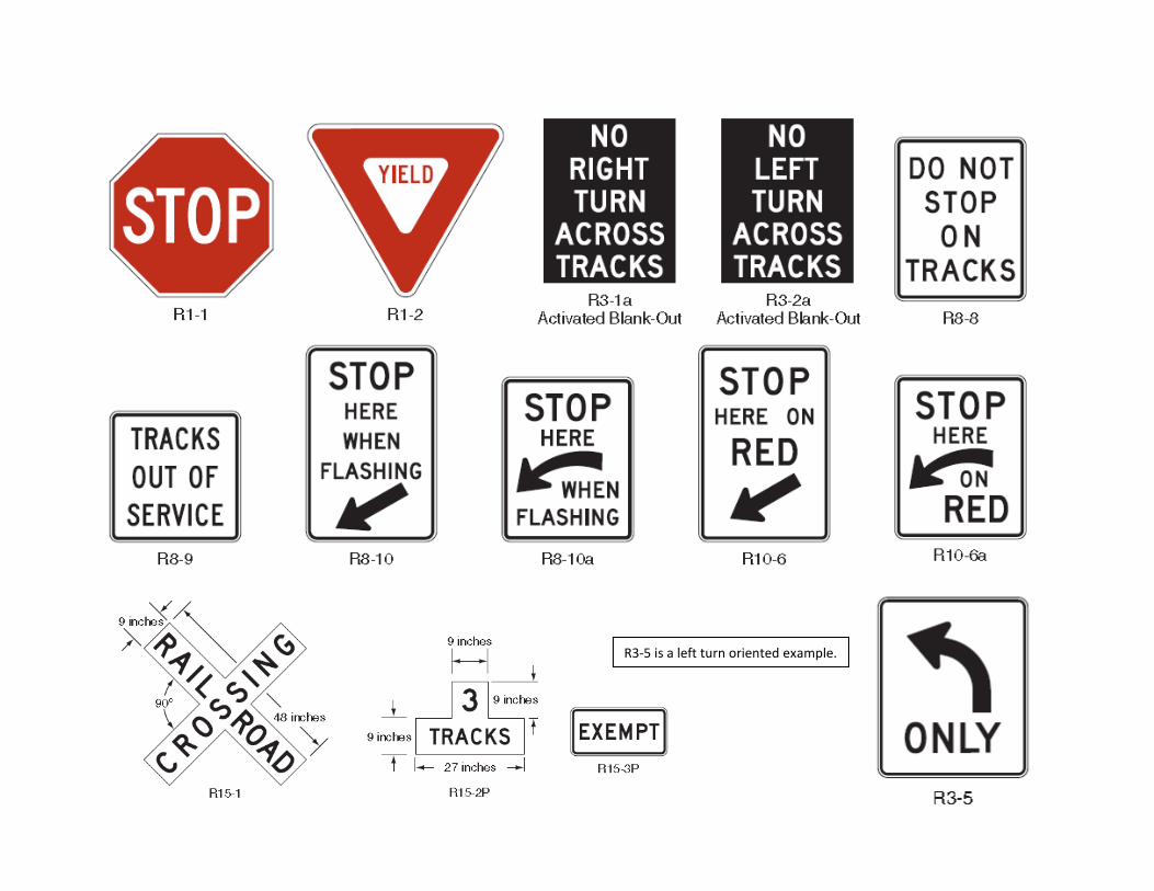
Passive Crossing Signage: Passive Crossing signage installed as part of a Section 130 Program should follow the current Manual on Uniform Traffic Control Devices (MUTCD) size and placement standards and applicable Federal Railroad Administration regulations, and shall consist of: Retro reflective crossbuck (R15-1). Required at both passive and active warning
crossings.
Retro reflective yield sign (R1-2). A stop sign (R1-1) may be placed in lieu of a yield sign due to field conditions. Required at passive warning crossings only.
Emergency Notification System (ENS) sign facing each direction of traffic that contains the unique USDOT crossing number for the crossing, a railroad emergency phone number, and milepost and/or road name. Required at both passive and active warning crossings.
Retro reflective ‘multiple track’ sign (R15-2P) if more than one track exists at crossing. Required at both passive and active warning crossings.
Signage should be mounted on break-away posts or other collision protection measures
and should be mounted at least 15 feet from edge of track. All signs described above should where possible be mounted on the same post facing
each direction of traffic at the crossing and installed on the right side of the roadway of each approach. The post shall also contain retro reflective strips. This is known as the “Crossbuck Assembly”. See Exhibit A for signage examples.
Crossbuck assembly signage is typically the maintenance responsibility of the railroad
once installed. In lieu of Section 130 assistance, it is the railroad’s responsibility to install crossbuck assemblies at crossings at their own cost unless set forth otherwise in a crossing agreement between the railroad and the road owner/authority.
Placement of passive warning signage shall comply with current MUTCD standards.
Advanced Crossing Warning Signage and Striping: Advanced Warning signage and striping shall comply with MUTCD standards and will typically consist of: Advanced Warning sign (W10-1) placed in advance of each approach to the railroad
crossing, or in the case that the approach is less than 75 feet from an intersecting

Page 14 of 15
highway, the Advanced Warning Sign (W10-2, W10-3, W10-4)) shall be installed on the intersected highway on each approach to the highway intersection.
Advanced warning striping should be placed typically adjacent to the Advanced Warning
sign (W10-1). Stop bar pavement markings should be placed immediately in front of the crossbuck assembly or flashing lights and gate mast, but no closer than 15’ from the rail, indicating to vehicles where to come to a safe stop in order to look for or wait for trains to pass. This signage is typically the maintenance responsibility of the road authority (i.e. City, County, State) that owns the road once installed under the Section 130 Program.
Railroad crossings should be signed and striped as a “No Passing Zone”.
In lieu of Section 130 assistance, it is typically the road authority’s responsibility to
install signage and striping at their cost. See Exhibit A for signage examples. See Exhibit B for striping example.
Placement of advanced warning signage and pavement markings should follow current
MUTCD standards.
Other Warning Signage: Additional signage may be warranted at a railroad crossing such as “Do Not Stop on Tracks” or “Stop Here on Red”. These signs are typically used at locations where a grade crossing is near or adjacent to a highway intersection and are typically the responsibility of the road authority to install and maintain at their cost. Needs for these additional signs can be determined from a field diagnostic review. See Exhibit A for sign examples. Medians: Medians should be of sufficient length to discourage vehicles from driving around lowered gates. While no regulations defines a minimum length, it is desirable to have a minimum of 100 feet in length except where an adjacent roadway intersection or nearby driveways make such a length unattainable. In these cases, a minimum of 60 feet in length is desirable. Medians should have non-traversable curbs on roads where speed limits are below 45 mph and where road width or other factors allow. Use of delineators attached to the median is also recommended to improve visibility and to encourage vehicles to slow on approach to the crossing. For installations where non-traversable curbs are not allowed or possible, or as a lower cost alternative, use of “Qwick Kurb” can be an option to consider. The end of the median shall be no closer than 10 feet from the center-line of track. The end of the median may be further than 10 feet from the center line of track but in no case shall be farther away than the location of the gate masts.

Page 15 of 15
Quad Gate installations: Quad Gate installations consist of a gate in each entrance and exit quadrant of a crossing. They may be used to prevent vehicles from driving around lowered gates (standard two gate installations) and are considered a more effective method then the use of medians, but at a much higher installation cost. It should be noted that a railroad may require the requesting entity be responsible for the costs of maintaining additional exit gate installations. † Not all passive crossings may have conditions that will warrant the best use of funds for installation of lights and gates. Considerations will include factors such as sight distance for motorists while approaching or stopped at a crossing, train speeds, train volumes, and roadway speed and traffic volume (is a crossing heavily used in a commercial, residential, or institutional area, or is the crossing rural with very few users) ‡ Constant Warning Time approach circuitry may not be required in certain field conditions where heavy switching activity exists near industry tracks or yards, or on certain sidings, or where the track speed is approximately 10-15 mph.
END OF TEXT DOCUMENT

EXHIBIT A-1
R1-1 R1-2 R3-1a
Activated Blank-Out R3-2a
Activated Blank-Out R8-8
R8-9 R8-10 R8-10a R10-6 R10-6a
9 inches 9 inches
90º 48 inches
9 inches
9 inches
R15-1
27 inches R15-2P
R15-3P R15-6
R15-6a R15-7 R15-7a R15-8

EXHIBIT A-2
ADVANCED WARNING SIGNS
W10-1
a W10-7
Activated Blank-Out
NO GATES OR LIGHTS
W10-13P
(EXEMPrll W10-1aP
W10-8
NEXT CROSSING
W10-14P
W10-2
W10-9
USE NEXT CROSSING
W10-14aP
NO TRAIN HORN
W10-9P
ROUGH CROSSING
W10-15P
W10-3
LOW GROUND CLEARANCE II W1 0-5P
W10-4
l' 100 FEET 150 FEET
BETWEEN BETWEEN
TRACKS AND HIGHWAY AND
HIGHWAY TRACKS
BEHIND YO U
W10-11 W1 0-11 a W1 0-11 b W10-12
Note: The W1 0-11 sign is a W1 0-3 sign modified for geometries. Other signs can be oriented or revised as needed to better portray the geometries of the roadways and the tracks.

EXHIBIT A-3 CROSSBUCK ASSEMBLY SAMPLE
* Height may be varied as required by local conditions and may be increased to accommodate signs mounted below the Crossbuck sign
** Measured to the ground level at
the base of the support
9 ft*
See Notes 2, 3
OR
2-inch white or red retroreflective strip on front
2 ft MAX.**
Notes:
Edge of roadway
2-inch white retroreflective strip on back of support
1. YIELD or STOP signs are used only at passive crossings. A STOP sign is used only if an engineering study determines that it is appropriate for that particular approach.
2. Mounting height shall be at least 4 feet for installations of YIELD or STOP signs on existing Crossbuck sign supports. 3. Mounting height shall be at least 7 feet for new installations in areas with pedestrian movements or parking.
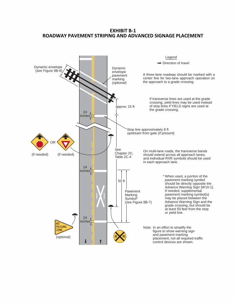
EXHIBIT B-1 ROADWAY PAVEMENT STRIPING AND ADVANCED SIGNAGE PLACEMENT
Dynamic envelope (see Figure 8B-8)
Dynamic envelope pavement marking (optional)
Legend
Direction of travel A three-lane roadway should be marked with a center line for two-lane approach operation on the approach to a grade crossing.
24 inches
approx. 15 ft
If transverse lines are used at the grade crossing, yield lines may be used instead of stop lines if YIELD signs are used at the grade crossing.
Stop line approximately 8 ft upstream from gate (if present)
OR
(if needed) (if needed)
24 inches
See Chapter 2C, Table 2C-4
50 ft
Pavement Marking Symbol*
On multi-lane roads, the transverse bands should extend across all approach lanes, and individual RXR symbols should be used in each approach lane.
* When used, a portion of the pavement marking symbol should be directly opposite the Advance Warning Sign (W10-1). If needed, supplemental pavement marking symbol(s) may be placed between the
24 inches
(see Figure 8B-7) Advance Warning Sign and the grade crossing, but should be at least 50 feet from the stop or yield line.
(optional)
Note: In an effort to simplify the
figure to show warning sign and pavement marking placement, not all required traffic control devices are shown.

EXHIBIT B-2 ADVANCED PAVEMENT STRIPING DETAIL
8 ft* 16
15 ft 6.6 ft
16 ft
inches 16 inches
50 ft
6 ft 20 ft 20 ft
60 ft
1.6 ft
Center of lane
15 ft
6 ft 3.3 ft
24 inches 24 ft
*Width may vary according to lane width
24 inches
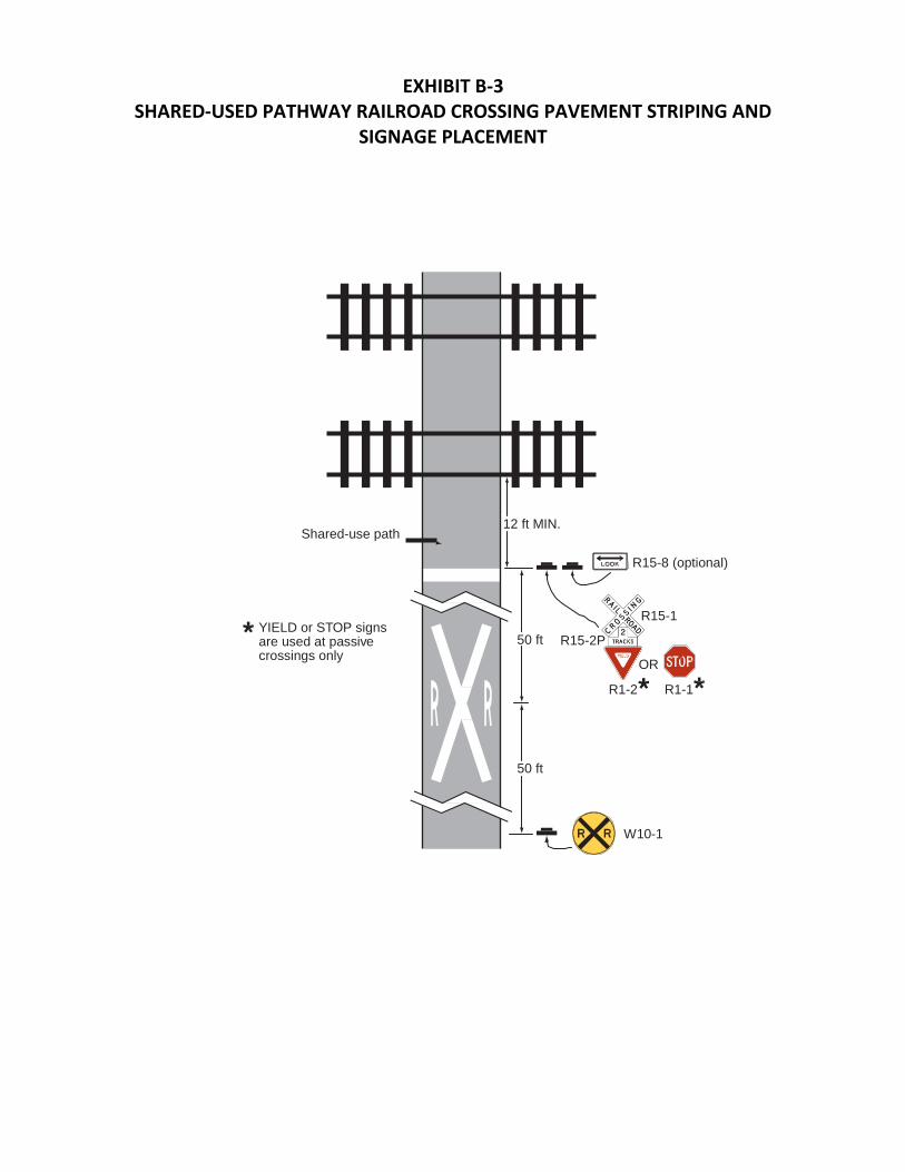
EXHIBIT B-3
SHARED-USED PATHWAY RAILROAD CROSSING PAVEMENT STRIPING AND SIGNAGE PLACEMENT
Shared-use path 12 ft MIN.
R15-8 (optional)
YIELD or STOP signs are used at passive crossings only
50 ft
R15-2P
R1-2
R15-1 OR
R1-1
50 ft
W10-1


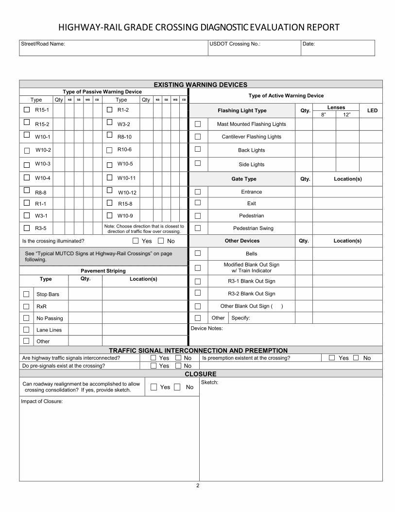
EXHIBIT D
RAILROAD CROSSING INVENTORY AND DIAGNOSTIC EVALUATION REPORT

R A I L HIGHWAY-RAIL GRADE CROSSING DIAGNOSTIC EVALUATION REPORT
LOCATION INFORMATION Railroad Name: County: City (In or Near):
R.R. Line / I.D.: Nearest R.R. Timetable Station: R.R. Milepost: ENS Sign Present? If Yes, #:
RAILROAD INFORMATION
DAILY TRAIN MOVEMENT* MAXIMUM SPEED OF TRAIN TYPE AND NUMBER OF TRACKS PASSENGER PASSENGER mph MAIN If Other, Specify: FREIGHT FREIGHT mph OTHER *CHECK IF LESS THAN ONE
MOVEMENT PER DAY
CROSSING ANGLE: Can two trains occupy crossing at same time? Yes No Can one train block the
motorist’s view of another train at the crossing?
YES NO
If Yes, explain: Crossing is Quiet Zone? Yes No
X
ing
Sur
face
TRACK SURFACE TYPE WIDTH (Feet) CONDITION (Poor, Fair, Good, New)
Crossing adjacent or within railyard? Yes No TEN-YEAR ACCIDENT DATA
TOTAL ACCIDENTS Number with
Injuries Number with Fatalities Number with
Property Damage Only
Have any near misses occurred? Yes No Explain:
Adjacent Railroad Crossings within ¼ Mile
USDOT No. Street/Road Name Warning Devices AADT
Street/Road Name: USDOT Crossing No.: Date:
DIAGNOSTIC INFORMATION
Funded By: SECTION130 STATE RR OTHER
Purpose of Diagnostic:
Initiated By: STATE RR LOCAL OTHER
HIGHWAY-RAIL GRADE CROSSING DIAGNOSTIC EVALUATION REPORT
Street/Road Name: USDOT Crossing No.: Date:
EXISTING WARNING DEVICES Type of Passive Warning Device
Type of Active Warning Device Type Qty NB SB WB EB Type Qty NB SB WB EB
R15-1
R1-2 Flashing Light Type Qty. Lenses LED 8” 12”
R15-2
W3-2 Mast Mounted Flashing Lights
W10-1
R8-10 Cantilever Flashing Lights
W10-2
R10-6 Back Lights
W10-3
W10-5 Side Lights
W10-4
W10-11 Gate Type Qty. Location(s)
R8-8
W10-12 Entrance
R1-1
R15-8 Exit
W3-1
W10-9 Pedestrian
R3-5 Note: Choose direction that is closest to direction of traffic flow over crossing.
Pedestrian Swing
Is the crossing illuminated? Yes No Other Devices Qty. Location(s)
See “Typical MUTCD Signs at Highway-Rail Crossings” on page following.
Bells
Modified Blank Out Sign w/ Train Indicator
Pavement Striping
Type Qty. Location(s) R3-1 Blank Out Sign
Stop Bars R3-2 Blank Out Sign
RxR Other Blank Out Sign ( )
No Passing Other Specify:
Lane Lines Device Notes:
Other TRAFFIC SIGNAL INTERCONNECTION AND PREEMPTION
Are highway traffic signals interconnected? Yes No Is preemption existent at the crossing? Yes No Do pre-signals exist at the crossing? Yes No
CLOSURE
Can roadway realignment be accomplished to allow crossing consolidation? If yes, provide sketch.
Yes No Sketch:
Impact of Closure:
2
R3-5 is a left turn oriented example.

Sign examples from pages 753 & 759 of 2009 MUTCD. R3-5 example is from http://www.trafficsign.us/r3.html
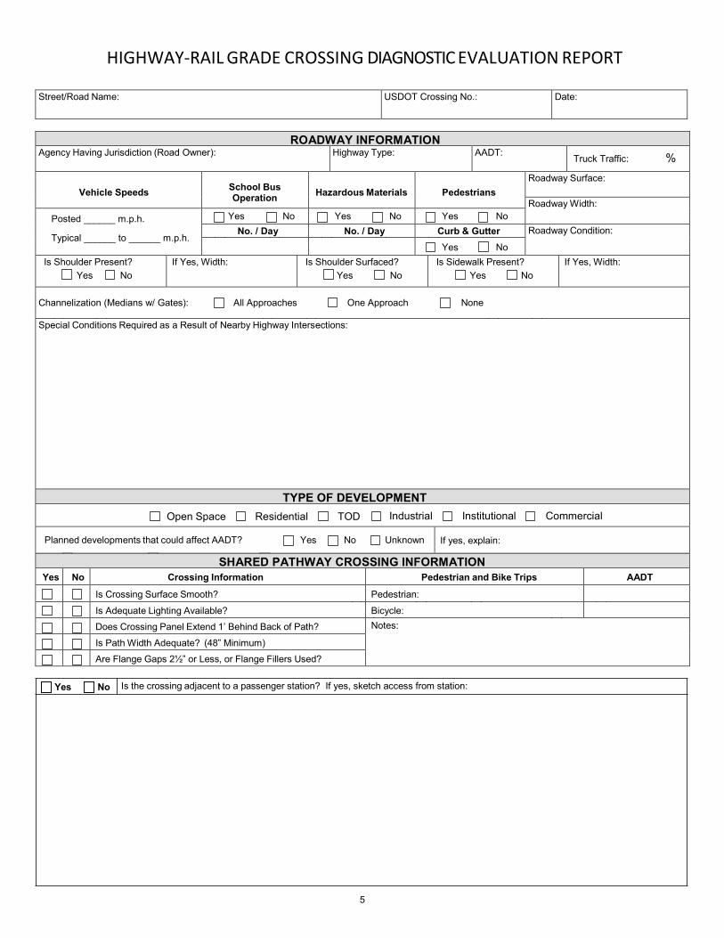
HIGHWAY-RAIL GRADE CROSSING DIAGNOSTIC EVALUATION REPORT
Street/Road Name: USDOT Crossing No.: Date:
ROADWAY INFORMATION
Agency Having Jurisdiction (Road Owner): Highway Type: AADT: Truck Traffic: %
Vehicle Speeds
School Bus Operation
Hazardous Materials
Pedestrians
Roadway Surface:
Roadway Width: Posted ______ m.p.h.
Typical ______ to ______ m.p.h.
Yes No Yes No Yes No No. / Day No. / Day Curb & Gutter Roadway Condition:
Yes No Is Shoulder Present?
Yes No If Yes, Width: Is Shoulder Surfaced?
Yes No
Is Sidewalk Present? Yes No
If Yes, Width:
Channelization (Medians w/ Gates): All Approaches One Approach None
Special Conditions Required as a Result of Nearby Highway Intersections:
TYPE OF DEVELOPMENT Open Space Residential TOD Industrial Institutional Commercial
Planned developments that could affect AADT? Yes No Unknown If yes, explain:
SHARED PATHWAY CROSSING INFORMATION Yes No Crossing Information Pedestrian and Bike Trips AADT
Is Crossing Surface Smooth? Pedestrian: Is Adequate Lighting Available? Bicycle: Does Crossing Panel Extend 1’ Behind Back of Path? Notes:
Is Path Width Adequate? (48” Minimum) Are Flange Gaps 2½” or Less, or Flange Fillers Used?
Yes No Is the crossing adjacent to a passenger station? If yes, sketch access from station:
5

HIGHWAY-RAIL GRADE CROSSING DIAGNOSTIC EVALUATION REPORT
Street/Road Name: USDOT Crossing No.: Date:
COMPREHENSIVE SKETCH OF CROSSING (Include location of warning devices, nearby schools, emergency services facilities, and other landmarks):
6
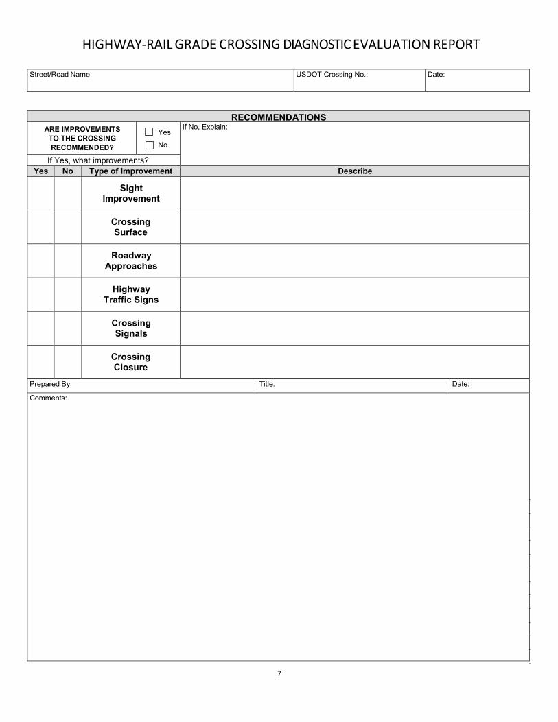
HIGHWAY-RAIL GRADE CROSSING DIAGNOSTIC EVALUATION REPORT
Street/Road Name: USDOT Crossing No.: Date:
RECOMMENDATIONS ARE IMPROVEMENTS
TO THE CROSSING RECOMMENDED?
Yes
No
If No, Explain:
If Yes, what improvements? Yes No Type of Improvement Describe
Sight
Improvement
Crossing Surface
Roadway
Approaches
Highway
Traffic Signs
Crossing Signals
Crossing Closure
Prepared By: Title: Date: Comments:
7

HIGHWAY-RAIL GRADE CROSSING DIAGNOSTIC EVALUATION REPORT
Street/Road Name: USDOT Crossing No.: Date:
DIAGNOSTIC ATTENDANCE No. Name Affiliation Phone No. E-Mail
1. 2. 3. 4. 5. 6. 7. 8. 9.
10. 11. 12. 13. 14. 15. 16. 17. 18. 19. 20.
CONTACTS (Contact name, agency or company, department, address, phone number, e-mail address)
School District:
Other (Specify):
Other (Specify):
Other (Specify):
Other (Specify):
Other (Specify):
Other (Specify):
8