new 9 faraday-222s law - universitas...
TRANSCRIPT

1
Faraday’s Law
2
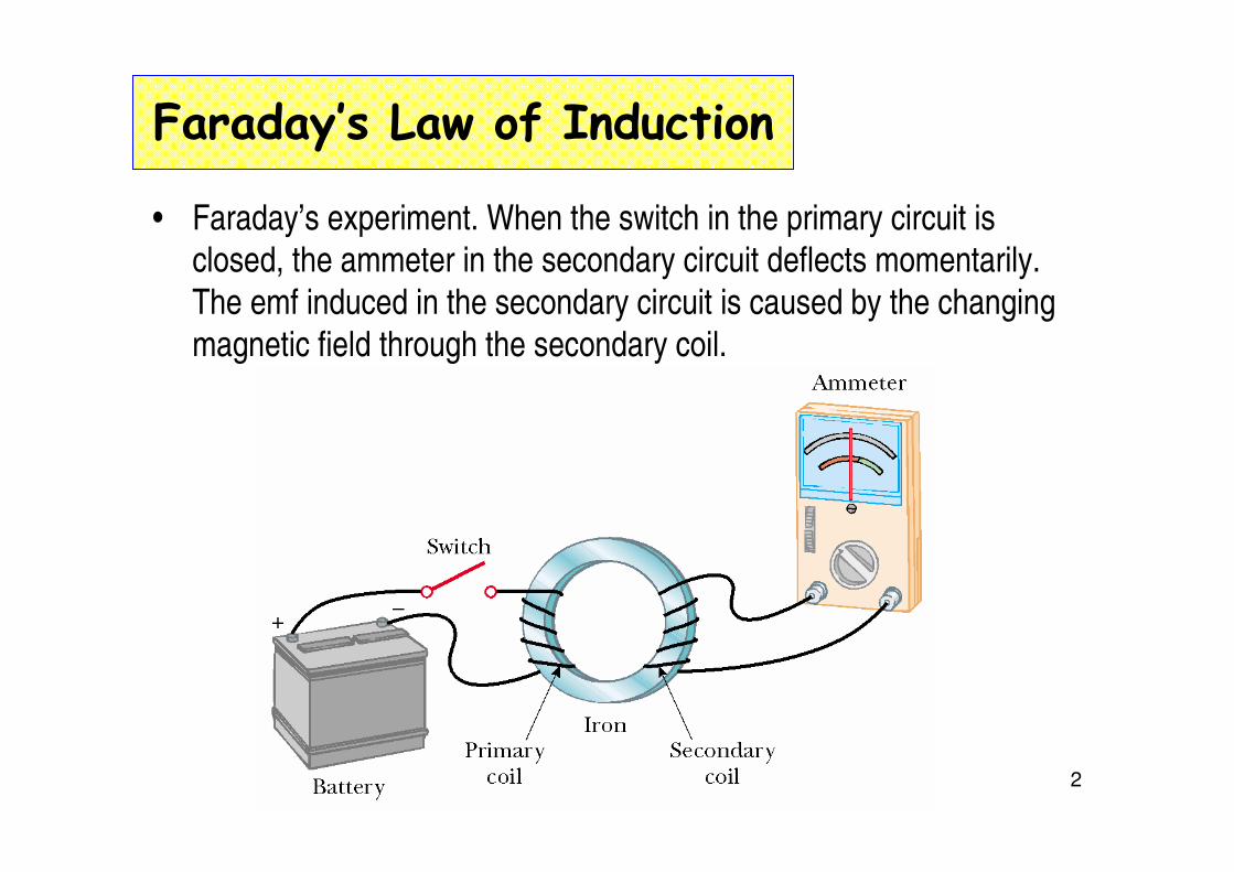
Faraday’s Law of Induction
• Faraday’s experiment. When the switch in the primary circuit is closed, the ammeter in the secondary circuit deflects momentarily.
The emf induced in the secondary circuit is caused by the changing
magnetic field through the secondary coil.
3
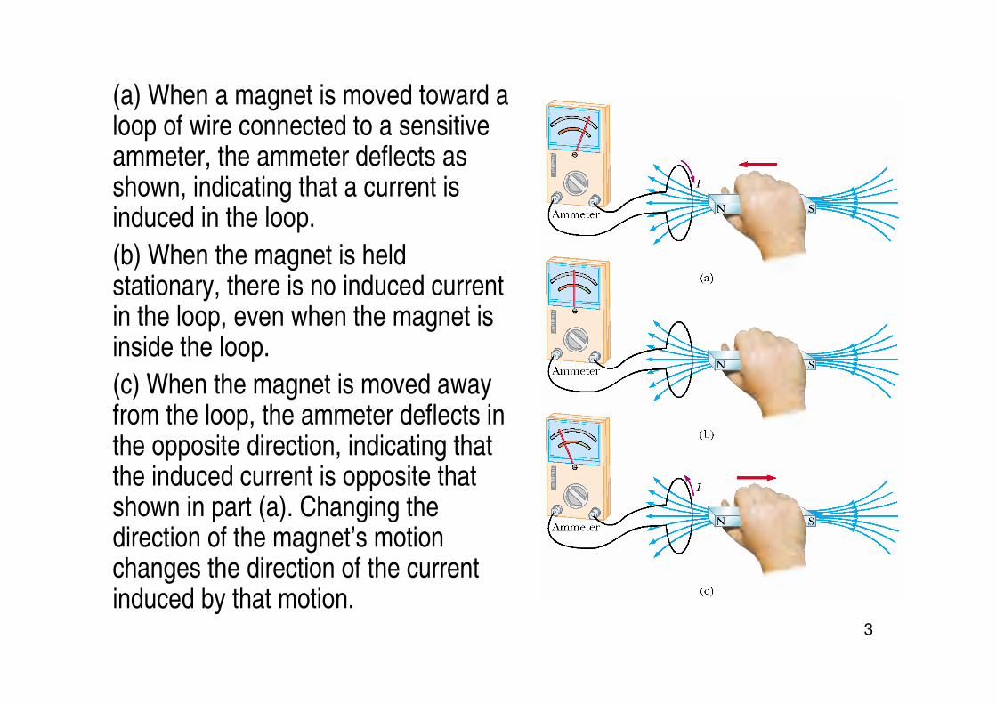
(a) When a magnet is moved toward a loop of wire connected to a sensitive ammeter, the ammeter deflects as shown, indicating that a current is induced in the loop.
(b) When the magnet is held stationary, there is no induced current in the loop, even when the magnet is inside the loop.
(c) When the magnet is moved away from the loop, the ammeter deflects in the opposite direction, indicating that the induced current is opposite that shown in part (a). Changing the direction of the magnet’s motion changes the direction of the current induced by that motion.

4
• an electric current can be induced or produced in a circuit (thesecondary circuit in our setup) by a changing magnetic field.
• The emf induced in a circuit is directly proportional to the time rate of change of the magnetic flux through the circuit.
• From this expression, we see that an emf can be induced in the
circuit in several ways:
– The magnitude of B can change with time.
– The area enclosed by the loop can change with time.
– The angle θ between B and the normal to
the loop can change with time.
– Any combination of the above can occur.

5
Quick Quiz 31.3
• Suppose you would like to steal power for your home from the electric company by placing a loop of wire near a transmission cable,
so as to induce an emf in the loop (an illegal procedure). Should you
(a) place your loop so that the transmission cable passes through your loop, or (b) simply place your loop near the transmission cable?
6
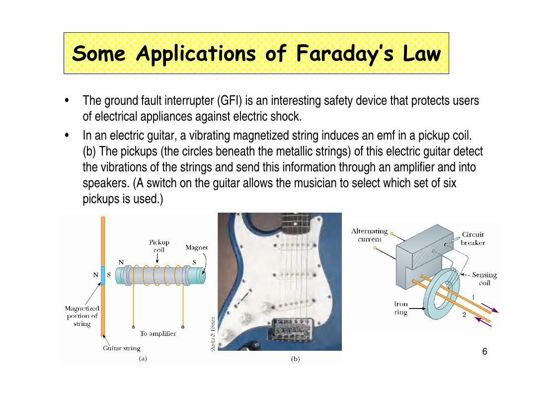
Some Applications of Faraday’s Law
• The ground fault interrupter (GFI) is an interesting safety device that protects users
of electrical appliances against electric shock.
• In an electric guitar, a vibrating magnetized string induces an emf in a pickup coil.
(b) The pickups (the circles beneath the metallic strings) of this electric guitar detect
the vibrations of the strings and send this information through an amplifier and into
speakers. (A switch on the guitar allows the musician to select which set of six
pickups is used.)

7
Motional emf
• A straight electrical conductor of length l Moving with a velocity v
through a uniform magnetic field B directed perpendicular to v. Due
to the magnetic force on electrons, the ends of the conductor
become oppositely charged. This establishes an electric field in the conductor. In steady state, the electric and magnetic forces on an
electron in the wire are balanced.
a potential difference is maintained between
the ends of the conductor as long as the
conductor continues to move through the
uniform magnetic field

8
• A conducting bar sliding with a velocity v along two conducting rails under the action of an applied force Fapp. The magnetic force F
B
opposes the motion, and a counterclockwise current I is induced in
the loop. (b) The equivalent circuit diagram for the setup shown in part (a).
• Motional emf

9
Lenz’s Law
The induced current in a loop is in the direction that creates a magnetic field that opposes the change in magnetic flux through the area enclosed by the loop.
As the conducting bar slides on the two fixed conducting rails, the magnetic flux due to the external magnetic field into the page through the area enclosed by the loop increases in time. By Lenz’s law, the induced current must be counterclockwise so as to produce a counteracting magnetic field directed out of the page. When the bar moves to the left, the induced current must be clockwise. Why?
10
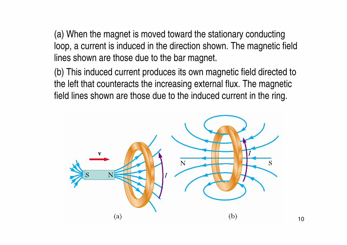
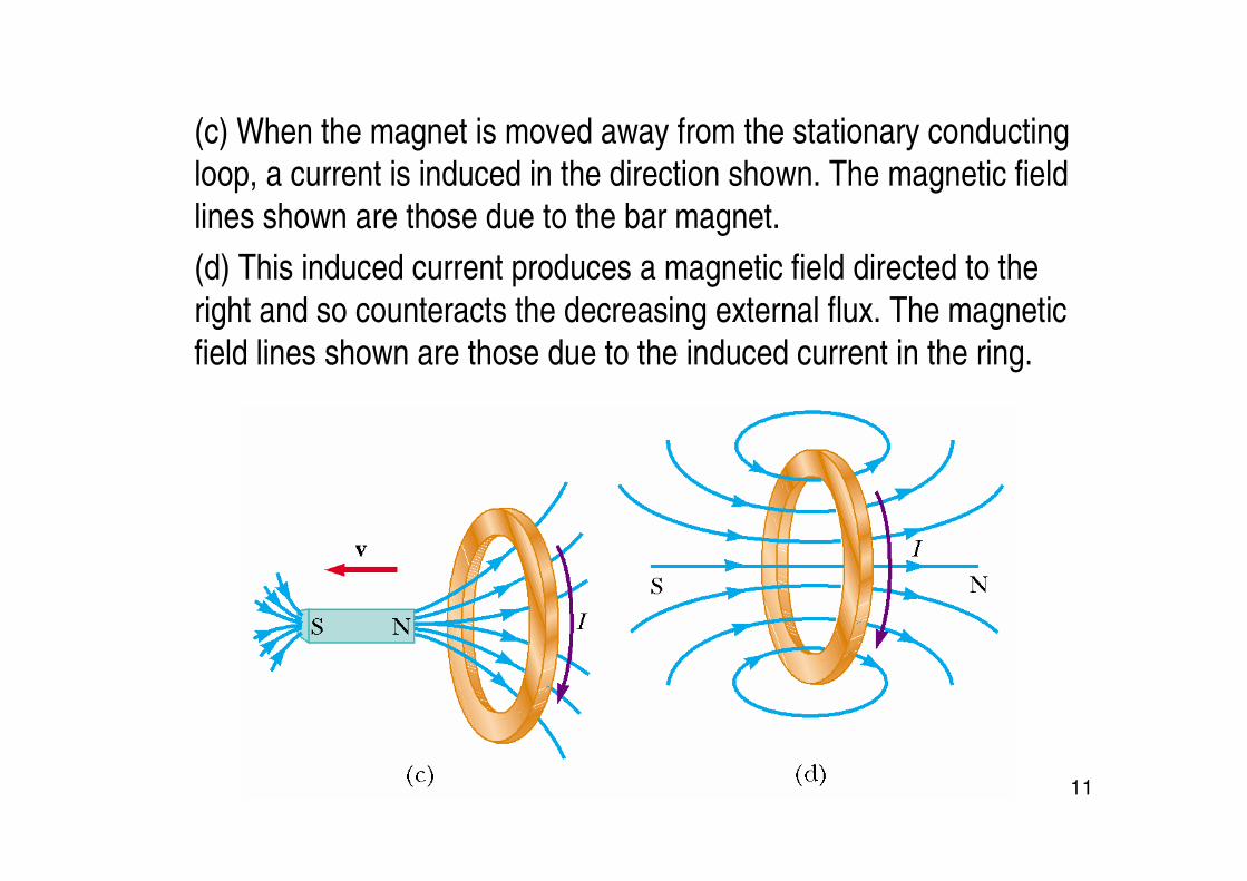
(a) When the magnet is moved toward the stationary conducting loop, a current is induced in the direction shown. The magnetic field
lines shown are those due to the bar magnet.
(b) This induced current produces its own magnetic field directed to
the left that counteracts the increasing external flux. The magnetic
field lines shown are those due to the induced current in the ring.
11
(c) When the magnet is moved away from the stationary conductingloop, a current is induced in the direction shown. The magnetic field
lines shown are those due to the bar magnet.
(d) This induced current produces a magnetic field directed to the
right and so counteracts the decreasing external flux. The magnetic
field lines shown are those due to the induced current in the ring.
12
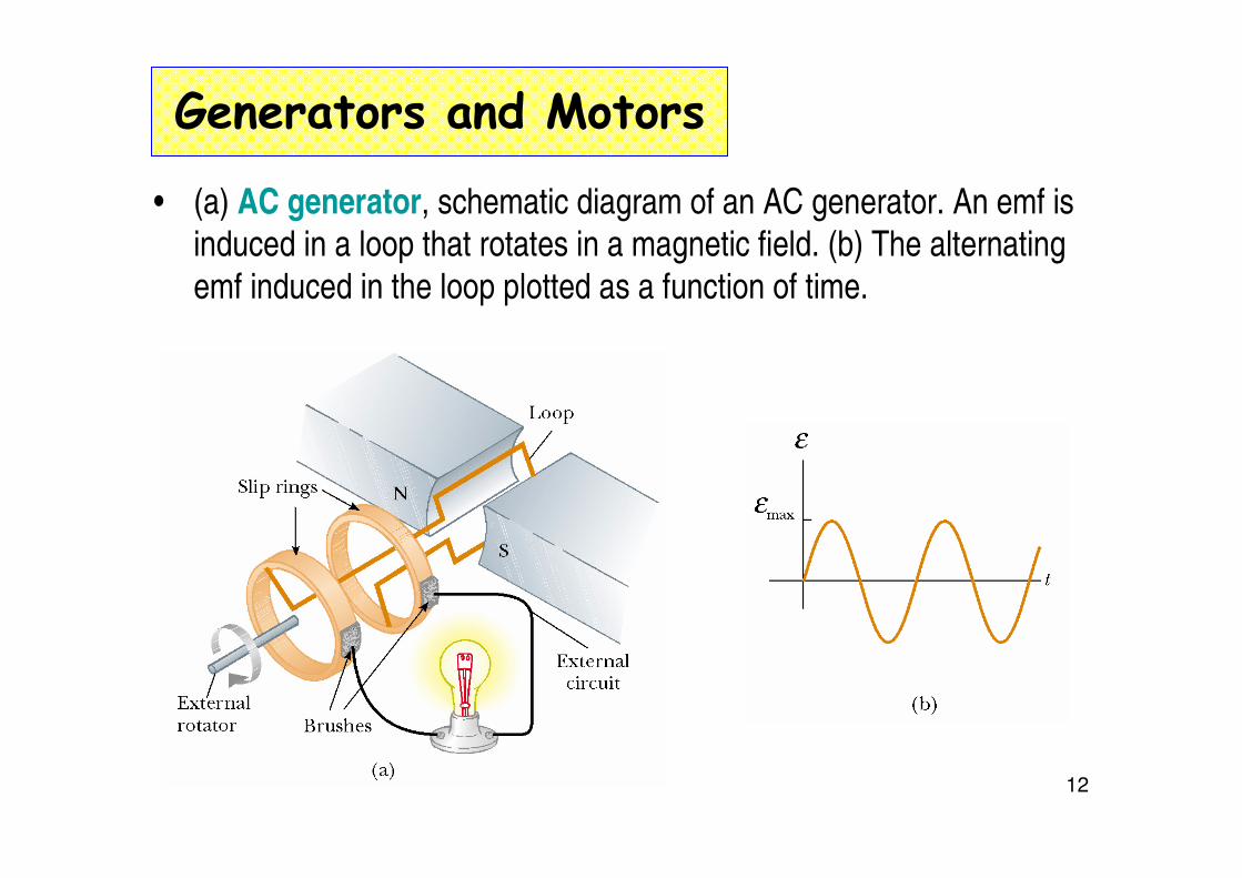
Generators and Motors
• (a) AC generator, schematic diagram of an AC generator. An emf is induced in a loop that rotates in a magnetic field. (b) The alternating
emf induced in the loop plotted as a function of time.
13
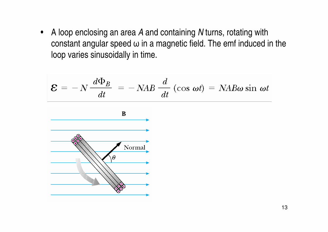
• A loop enclosing an area A and containing N turns, rotating with constant angular speed ω in a magnetic field. The emf induced in the
loop varies sinusoidally in time.
14
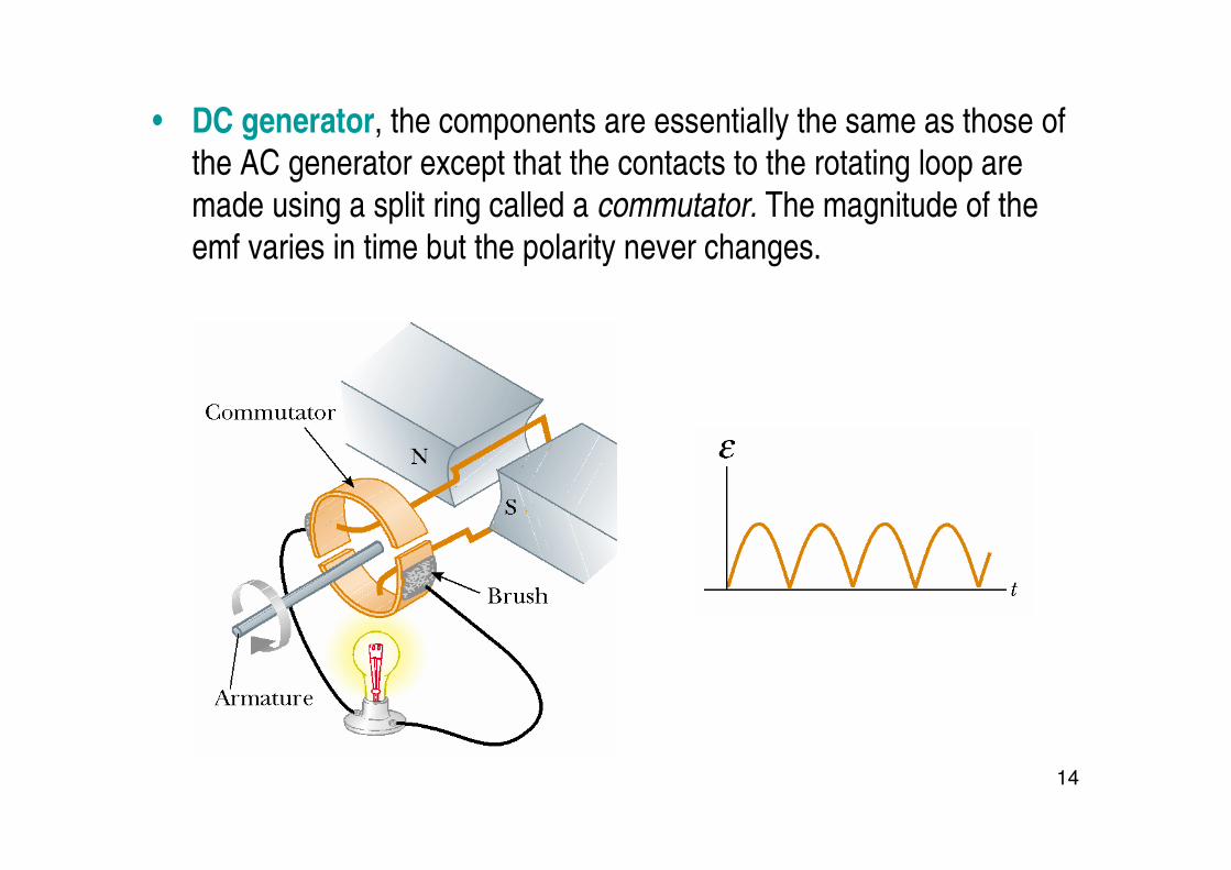
• DC generator, the components are essentially the same as those of the AC generator except that the contacts to the rotating loop are
made using a split ring called a commutator. The magnitude of the
emf varies in time but the polarity never changes.
15
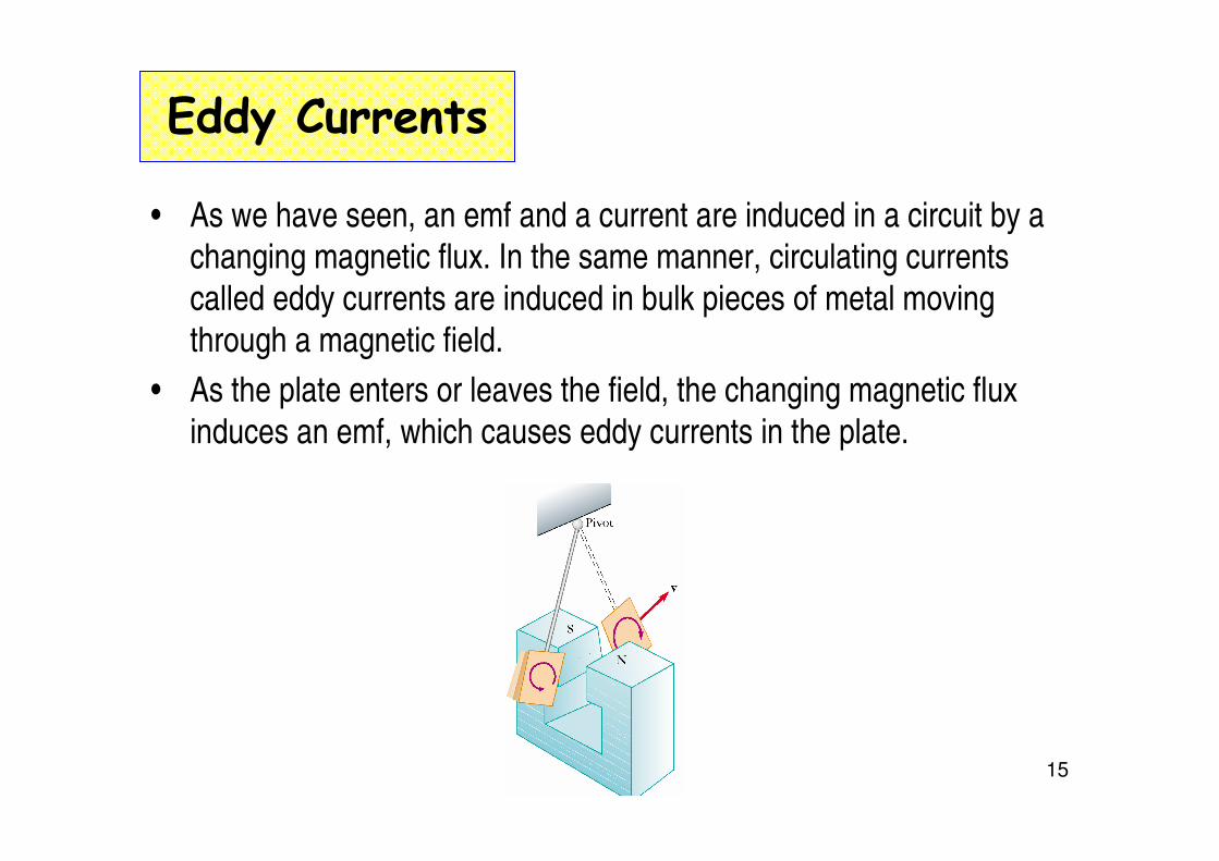
Eddy Currents
• As we have seen, an emf and a current are induced in a circuit by a changing magnetic flux. In the same manner, circulating currents
called eddy currents are induced in bulk pieces of metal moving
through a magnetic field.
• As the plate enters or leaves the field, the changing magnetic flux
induces an emf, which causes eddy currents in the plate.

16
(a) As the conducting plate enters the field (position 1), the eddy currents are counterclockwise. As the plate leaves the field (position
2), the currents are clockwise. In either case, the force on the plate is
opposite the velocity, and eventually the plate comes to rest.
(b) When slots are cut in the conducting plate, the eddy currents are
reduced and the plate swings more freely through the magnetic field.

17
Some applications

18
Quick Quiz
• In equal-arm balances from the early twentieth century, it is sometimes observed that an aluminum sheet hangs from one of the arms and passes between the poles of a magnet. This causes the oscillations of the equal-arm balance to decay rapidly. In the absence of such magnetic braking, the oscillation might continue for a very long time, so that the experimenter would have to wait to take a reading. The oscillations decay because (a) the aluminum sheet is attracted to the magnet; (b) currents in the aluminum sheet set up a magnetic field that opposes the oscillations; (c) aluminum is paramagnetic.
19
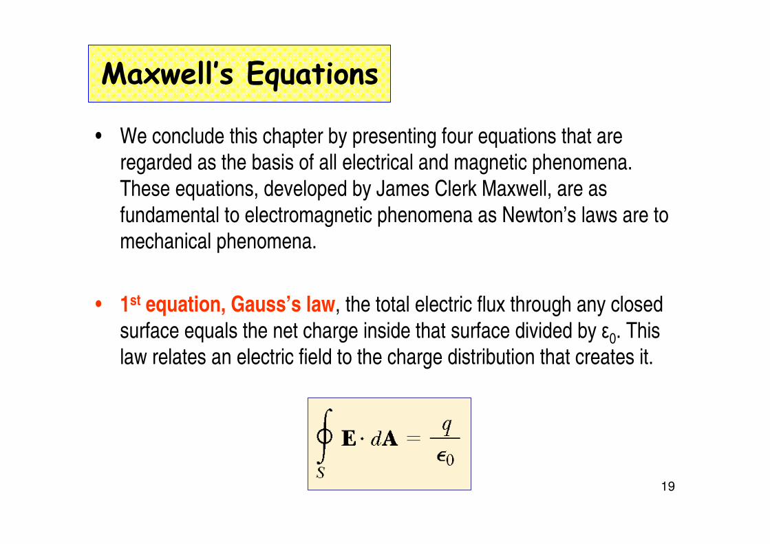
Maxwell’s Equations
• We conclude this chapter by presenting four equations that are regarded as the basis of all electrical and magnetic phenomena.
These equations, developed by James Clerk Maxwell, are as
fundamental to electromagnetic phenomena as Newton’s laws are to mechanical phenomena.
• 1st equation, Gauss’s law, the total electric flux through any closed
surface equals the net charge inside that surface divided by ε0. This law relates an electric field to the charge distribution that creates it.
20
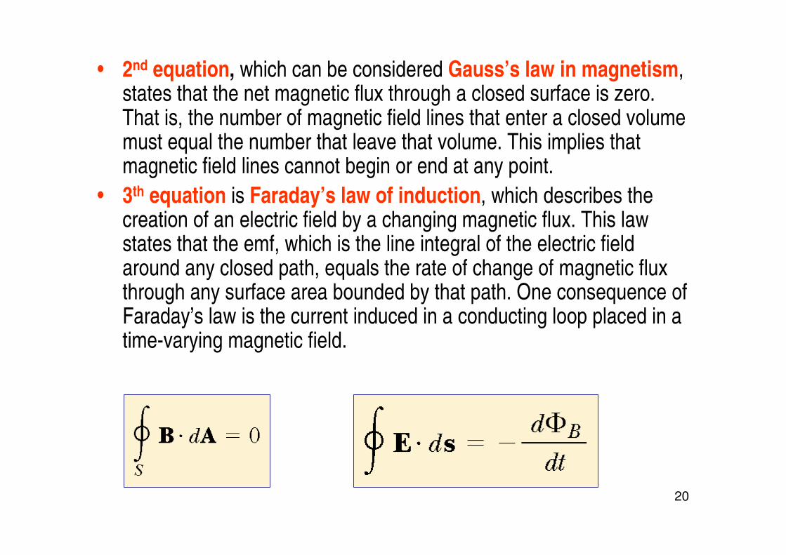
• 2nd equation, which can be considered Gauss’s law in magnetism, states that the net magnetic flux through a closed surface is zero. That is, the number of magnetic field lines that enter a closed volume must equal the number that leave that volume. This implies that magnetic field lines cannot begin or end at any point.
• 3th equation is Faraday’s law of induction, which describes the creation of an electric field by a changing magnetic flux. This law states that the emf, which is the line integral of the electric field around any closed path, equals the rate of change of magnetic flux through any surface area bounded by that path. One consequence of Faraday’s law is the current induced in a conducting loop placed in a time-varying magnetic field.

21
• 4th equation, usually called the Ampère–Maxwell law, is the generalized form of Ampère’s law, and describes the creation of a
magnetic field by an electric field and electric currents: the line
integral of the magnetic field around any closed path is the sum of times the net current through that path and µ0 ε0 times the rate of
change of electric flux through any surface bounded by that path.

22
example
• An instrument based on induced emf has been used to measure projectile speeds up to 6 km/s. A small magnet is imbedded in the projectile, as shown in figure. The projectile passes through two coils separated by a distance d. As the projectile passes through each coil a pulse of emf is induced in the coil. The time interval between pulses can be measured accurately with an oscilloscope, and thus the speed can be determined. (a) Sketch a graph of ∆V versus t for the arrangement shown. Consider a current that flows counterclockwise as viewed from the starting point of the projectile as positive. On your graph, indicate which pulse is from coil 1 and which is from coil 2. (b) If the pulse separation is 2.40 ms and d = 1.50 m, what is the projectile speed?
23
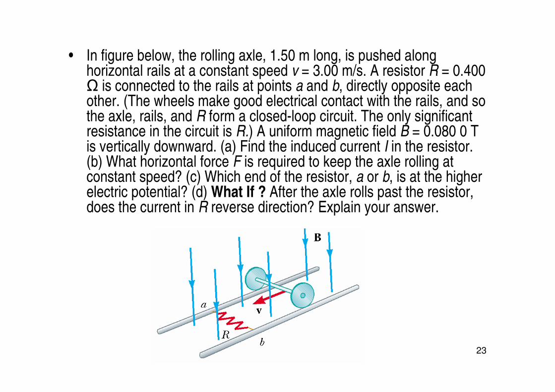
• In figure below, the rolling axle, 1.50 m long, is pushed along horizontal rails at a constant speed v = 3.00 m/s. A resistor R = 0.400 Ω is connected to the rails at points a and b, directly opposite each other. (The wheels make good electrical contact with the rails, and so the axle, rails, and R form a closed-loop circuit. The only significant resistance in the circuit is R.) A uniform magnetic field B = 0.080 0 T is vertically downward. (a) Find the induced current I in the resistor. (b) What horizontal force F is required to keep the axle rolling at constant speed? (c) Which end of the resistor, a or b, is at the higher electric potential? (d) What If ? After the axle rolls past the resistor, does the current in R reverse direction? Explain your answer.