networking fundamentals for dante - audio-technica · page 1 of 18 audio-technica u.s., inc....
TRANSCRIPT
Page 1 of 18
Audio-Technica U.S., Inc. 11/5/2014
Networking Fundamentals for Dante Overview Audinate’s Dante® is an audio solution that runs on top of standard Ethernet networks. With Audio-
Technica’s entrance into Dante-powered products, it is important to understand the fundamentals
behind basic computer networking. This document focuses on basic networking knowledge that will
help with designing, deploying, and supporting a network for Dante equipment.
Contents Background Theory ................................................................................................................................. 3
OSI Model............................................................................................................................................ 3
Layer 1: Physical .............................................................................................................................. 3
Layer 2: Data Link ............................................................................................................................ 3
Layer 3: Network ............................................................................................................................. 3
Layer 4: Transport ............................................................................................................................ 4
Layers 5, 6, and 7: Session, Presentation, and Application ................................................................ 4
Encapsulation ...................................................................................................................................... 4
Addressing ........................................................................................................................................... 5
MAC Addresses ................................................................................................................................ 5
IP Addressing ................................................................................................................................... 5
Components and Technologies ................................................................................................................ 8
Network Devices.................................................................................................................................. 8
Hubs ................................................................................................................................................ 8
Switches .......................................................................................................................................... 9
Routers .......................................................................................................................................... 10
Network Interface Cards .................................................................................................................... 11
Cabling and Ethernet ......................................................................................................................... 12
Network Speeds............................................................................................................................. 12
Power over Ethernet ...................................................................................................................... 12
DHCP ................................................................................................................................................. 12
VLANs ................................................................................................................................................ 12
Quality of Service............................................................................................................................... 13
Basic Network Configuration ................................................................................................................. 13
Configuring Network Equipment ........................................................................................................ 13
Page 2 of 18
Audio-Technica U.S., Inc. 11/5/2014
Configuring Hosts .............................................................................................................................. 14
Audinate Dante ..................................................................................................................................... 15
Dante Performance and Reliability ..................................................................................................... 15
Quality of Service Considerations ................................................................................................... 15
Congestion and Bottlenecks ........................................................................................................... 16
Security ......................................................................................................................................... 16
Troubleshooting ................................................................................................................................ 16
Layer 1 ........................................................................................................................................... 16
Layer 2 ........................................................................................................................................... 16
Layer 3 ........................................................................................................................................... 17
Layer 4 ........................................................................................................................................... 17
Layers 5, 6, and 7 ........................................................................................................................... 18
Page 3 of 18
Audio-Technica U.S., Inc. 11/5/2014
Background Theory A computer network is a group of computers and devices that can communicate and share information
with each other. The way these devices communicate is governed by a variety of protocols. Protocols in
computer networking serve the same purpose as protocols in the physical world: they are agreed sets of
procedures that all devices understand in order to accomplish a task.
Typically, computers use multiple protocols at any one time to complete a single task. This is because
protocols are designed to be modular in nature. These protocols are all organized in layers. The model
that best illustrates these layers is the OSI model.
OSI Model The Open Systems Interconnection (OSI) model is a model developed by the International Organization
for Standardization (ISO) that splits up the functions of network communication into seven layers. The
layers are numbered from bottom to top.
As data from an application moves from the top of the model down, the data is encapsulated by the
layer below it with information that will get it to its destination application. When the encapsulated data
arrives at the destination, it moves up the OSI model where each layer is then decapsulated until the
original data reaches the destination application.
Layer 1: Physical The physical layer determines what kind of physical medium communication occurs over. It is
responsible for how electrical impulses are transmitted over a copper cable or how light is modulated
over a fiber-optic cable. In the context of computer networking, this layer is concerned with the
transmission and reception of 1s and 0s and nothing else.
Layer 2: Data Link The data link layer determines how two or more devices talk to each other on a network. In most cases,
the Ethernet protocol is used here. Every Ethernet device has its own unique address that does not
change, called a MAC address. It usually looks something like 01:23:45:67:89:ab. Devices use MAC
addresses to communicate with each other on a network1.
The data link layer also provides redundancy to transmission problems on the physical layer. For
example, if two devices transmit at the same time, it will end in a collision and no data will be received.
The data link layer provides a way to detect this and retry the transmission.
Layer 3: Network The network layer is where routing occurs. In layer 2, communication can only occur among devices on
the same network segment. When a destination exists on another network, the communication must be
directed by a router to the other network2. A router joins two or more networks.
1 A layer 2 address is similar in function to a person’s name. Anyone nearby can communicate with them using that name. However, if they are not nearby then something like a mailing address or a phone number must be used to reach them. 2 A layer 3 address is analogous to a mailing address or a phone number. The post office or the telephone company acts as the router and connects the parties using their assigned addresses or numbers.
Page 4 of 18
Audio-Technica U.S., Inc. 11/5/2014
The address in layer 3 is what routers use to get communication to its destination. The layer 3 protocol
of the Internet – and the vast majority of computer networks – is the Internet Protocol (IP). Each device
is given an IP address. Unlike the MAC address, this address can change, though it usually stays the same
once assigned. This address usually looks something like 192.168.1.101.
Layer 4: Transport The transport layer is where end-to-end communication is established. In the IP suite, there are two
primary transport protocols, Transmission Control Protocol (TCP) and User Datagram Protocol (UDP).
The main difference between these two protocols is that TCP creates connections and always verifies
that traffic arrives at its destination. UDP has no concept of connections and delivers data on a best-
effort basis.
Both TCP and UDP use the concept of ports to sort traffic going to higher level services. For example, a
server may listen on port 21 for file transfers and on port 80 for a website. When another computer
wants to transfer files, it will connect on port 21. When it wants the website, it will connect on port 80.
The connecting computer will also specify a return port. The server will send its traffic to that port when
responding.
Layers 5, 6, and 7: Session, Presentation, and Application Layers 5–7 are layers that include the protocols that applications themselves use to communicate. In the
case of Dante, these layers might contain the digital audio or timing information. A network engineer,
however, is not normally concerned with these layers as they don’t affect routing.
Encapsulation Data from the sending application flows down from the application layer all the way to the physical layer
where it is transmitted out on the network. The final recipient of the data receives it on the physical
layer and sends it up to the application layer where the receiving application resides. This process is
illustrated in Figure 1.
Page 5 of 18
Audio-Technica U.S., Inc. 11/5/2014
Application Data
Application DataTCP Header
Application DataTCP HeaderIP Header
Application DataTCP HeaderIP HeaderEthernet Header
Application
Presentation
Sesssion
Transport
Network
Data Link
Physical 0010101011010101011011011110111010100100110111010001101
FCS
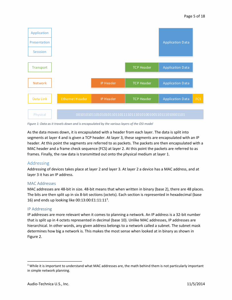
Figure 1: Data as it travels down and is encapsulated by the various layers of the OSI model
As the data moves down, it is encapsulated with a header from each layer. The data is split into
segments at layer 4 and is given a TCP header. At layer 3, these segments are encapsulated with an IP
header. At this point the segments are referred to as packets. The packets are then encapsulated with a
MAC header and a frame check sequence (FCS) at layer 2. At this point the packets are referred to as
frames. Finally, the raw data is transmitted out onto the physical medium at layer 1.
Addressing Addressing of devices takes place at layer 2 and layer 3. At layer 2 a device has a MAC address, and at
layer 3 it has an IP address.
MAC Addresses MAC addresses are 48-bit in size. 48-bit means that when written in binary (base 2), there are 48 places.
The bits are then split up in six 8-bit sections (octets). Each section is represented in hexadecimal (base
16) and ends up looking like 00:13:00:E1:11:113.
IP Addressing IP addresses are more relevant when it comes to planning a network. An IP address is a 32-bit number
that is split up in 4 octets represented in decimal (base 10). Unlike MAC addresses, IP addresses are
hierarchical. In other words, any given address belongs to a network called a subnet. The subnet mask
determines how big a network is. This makes the most sense when looked at in binary as shown in
Figure 2.
3 While it is important to understand what MAC addresses are, the math behind them is not particularly important in simple network planning.

Page 6 of 18
Audio-Technica U.S., Inc. 11/5/2014
Figure 2: An IP address (192.168.1.101) and subnet mask (255.255.255.0) being combined to deduce the network's address
There is a dividing line in the subnet mask where every bit on the left is a 1 and every bit on the right is a
0. This dividing line is applied to the IP address and splits it into two parts, the network portion (on the
left) and the host portion (on the right). The network portion of a device’s IP address determines what
network it is in and the host portion uniquely identifies it from other devices on that network.
Substituting the host portion of the address with all 0s leaves the network number4. The network
number represents the entire network. The network number is the first address in the network and
cannot be assigned to a host.
So in the case of Figure 2, a device configured with an address of 192.168.1.101 and mask of
255.255.255.0 is a member of the 192.168.1.0/24 network. The /24 represents the subnet mask and is
just a count of the number of 1s in the mask.
Address Classes
In IP, there are five different classes of networks. Originally, these classes determined how large a
network would be. This was later changed to allow subnet masks of variable lengths. The five classes are
Class A – Class E. Class A, B, and C are used to address any single host on the Internet.
Class A networks always begin with a 0 as the leftmost binary digit and have a subnet mask of /8. Any
address between 0.0.0.0 and 127.255.255.255 is in Class A. Class B networks always begin with 10 as the
two leftmost binary digits and have a subnet mask of /16. Any address between 128.0.0.0 and
191.255.255.255 is in Class B. Class C networks always begin with 110 as the three leftmost binary digits
and have a subnet mask of /16. Any address between 192.0.0.0 and 223.255.255.255 is in class C.
Class D is used for multicast addresses. A multicast address represents multiple devices with one
address. Class D addresses always begin with 1110 as the four leftmost digits and have no subnet mask.
Any address from 224.0.0.0 to 239.255.255.255 is in Class D.
Class E is marked as experimental and its addresses are usually considered invalid. The four leftmost bits
of a Class E address are always 1111 and there is no subnet mask. Any address from 240.0.0.0 to
255.255.255.255 is in Class E.
4 This substitution is the same as performing a binary AND operation between the address and the mask, which is what is shown in the figure. A binary AND simply compares each place and returns a 1 if both numbers are a 1 and a 0 otherwise.
Address: 192 .168 .1 .101 (Binary) 1 1 0 0 0 0 0 0 .1 0 1 0 1 0 0 0 .0 0 0 0 0 0 0 1 .0 1 1 0 0 1 0 1 Mask: 1 1 1 1 1 1 1 1 .1 1 1 1 1 1 1 1 .1 1 1 1 1 1 1 1 .0 0 0 0 0 0 0 0 255 .255 .255 .0 AND ------------------------------------------------------------------ Network: 1 1 0 0 0 0 0 0 .1 0 1 0 1 0 0 0 .0 0 0 0 0 0 0 1 .0 0 0 0 0 0 0 0 192 .168 .1 .0
Page 7 of 18
Audio-Technica U.S., Inc. 11/5/2014
Currently, the address space for standard hosts on the Internet is between 0.0.0.0 and 223.255.255.255.
The space between 224.0.0.0 to 239.255.255.255 is used for multicast and the remaining space is
unused.
Private Addresses
There are three ranges of IP addresses in the usable address space of IP that are considered private.
These addresses do not exist on the Internet and are reserved for use inside of a private network. Most
home networks and corporate networks use these private addresses as it reduces the need for a large
number of public IP addresses.
The three ranges of private addresses are 10.0.0.0/8, 172.16.0.0/12, and 192.168.0.0/16. Additionally,
the 127.0.0.0/8 network is reserved for loopback addresses, addresses that are local within a single host.
Subnetting
The subnet mask determines the size of the network. The number of addresses that can fit in a network
are determined by the host portion of the mask. For example, with a subnet mask of /24
(255.255.255.0), the host portion is eight bits long. Eight bits is enough space for 256 unique numbers
(0–256 in decimal or 0–11111111 in binary). That means that in any /24 network, there are 256 unique
addresses. There can only be at most 254 hosts, however, as the first address is the network number
and the last address is reserved as a broadcast address to address all hosts in the network.
Subnetting is the splitting up of a network into smaller networks. For example, a business may have one
large network assigned to it. But since it is not practical to have every device on the same network, the
business would most likely subnet the address into smaller networks for different floors of the building
or for different device types like servers, workstations, and phones. An example of subnetting a /16
network is shown in Figure 3.
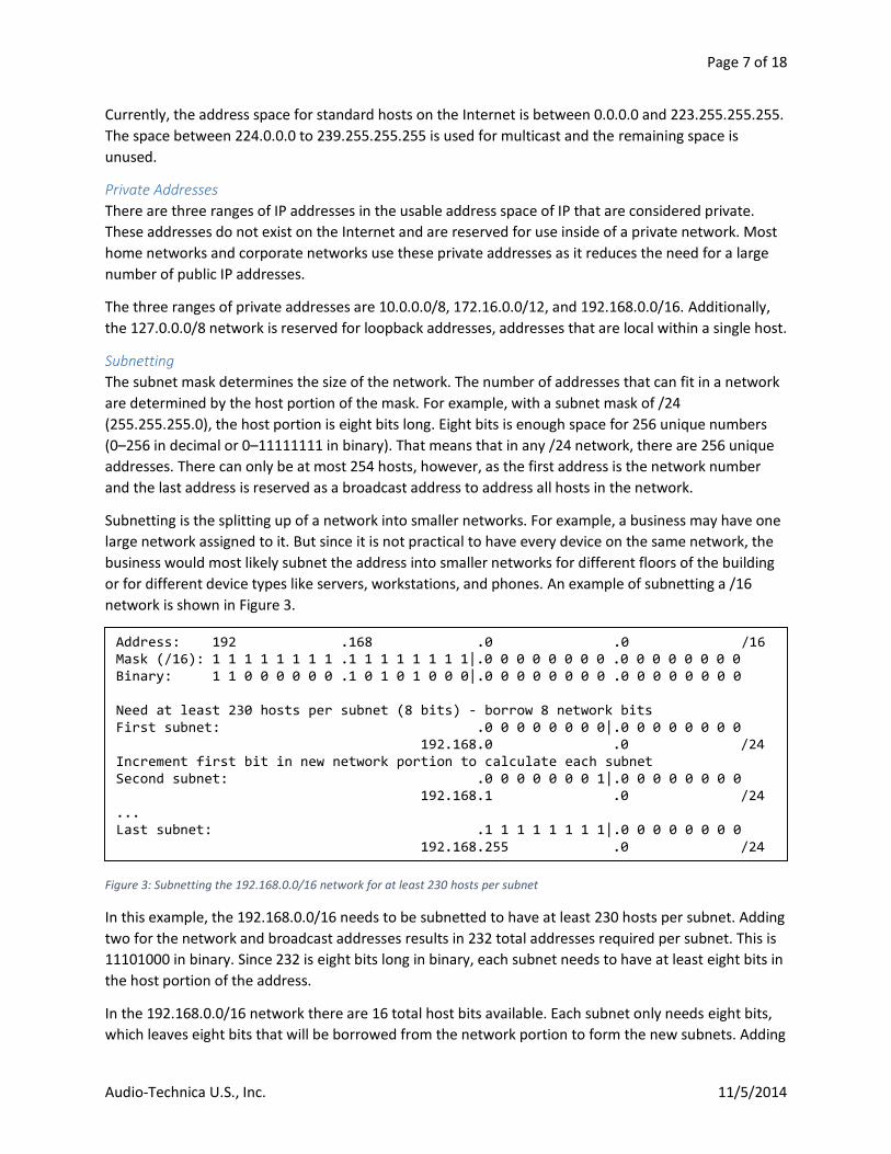
Figure 3: Subnetting the 192.168.0.0/16 network for at least 230 hosts per subnet
In this example, the 192.168.0.0/16 needs to be subnetted to have at least 230 hosts per subnet. Adding
two for the network and broadcast addresses results in 232 total addresses required per subnet. This is
11101000 in binary. Since 232 is eight bits long in binary, each subnet needs to have at least eight bits in
the host portion of the address.
In the 192.168.0.0/16 network there are 16 total host bits available. Each subnet only needs eight bits,
which leaves eight bits that will be borrowed from the network portion to form the new subnets. Adding
Address: 192 .168 .0 .0 /16 Mask (/16): 1 1 1 1 1 1 1 1 .1 1 1 1 1 1 1 1|.0 0 0 0 0 0 0 0 .0 0 0 0 0 0 0 0 Binary: 1 1 0 0 0 0 0 0 .1 0 1 0 1 0 0 0|.0 0 0 0 0 0 0 0 .0 0 0 0 0 0 0 0 Need at least 230 hosts per subnet (8 bits) - borrow 8 network bits First subnet: .0 0 0 0 0 0 0 0|.0 0 0 0 0 0 0 0 192.168.0 .0 /24 Increment first bit in new network portion to calculate each subnet Second subnet: .0 0 0 0 0 0 0 1|.0 0 0 0 0 0 0 0 192.168.1 .0 /24 ... Last subnet: .1 1 1 1 1 1 1 1|.0 0 0 0 0 0 0 0 192.168.255 .0 /24
Page 8 of 18
Audio-Technica U.S., Inc. 11/5/2014
the eight borrowed bits to the original 16 network bits leaves /24 as the new subnet mask of each
subnet. To calculate each possible subnet, the borrowed bits are incremented from 0 until the maximum
is reached. In this case, the maximum is eight bits long at 11111111 in binary or 256 in decimal.
These subnets can then be further subnetted into smaller sections if needed.
Unicast, Multicast, and Broadcast
Unicast represents one-to-one communication. Multicast represents one-to-many communication.
Broadcast represents one-to-all communication.
Any traffic between two hosts is unicast. Broadcast and multicast differ in that broadcast is sent to
everyone and multicast is only sent to those registered under that multicast address5. In any network,
the last available address is the broadcast address. For example, in the 192.168.1.0/24 network the
broadcast address is 192.168.1.255. Multicast addresses exist in the space of 224.0.0.0–
239.255.255.255. Multiple devices can register for an address in this range and will then receive any
traffic destined to that address.
Components and Technologies
Network Devices Network devices are special devices in a network because they forward traffic for others. They do not
normally send or receive their own traffic except for management. Because they only need to direct the
traffic, these devices do not examine all seven layers. Each type of device operates in a specific layer and
only processes data up to that layer.
Hubs Hubs are the simplest of any network device. They operate only at the physical layer, layer 1. When they
receive data on a port they do nothing more than duplicate that data out every other port as seen in
Figure 4.
5 In the case of Dante, broadcasting and multicasting is preferable any time a device is sending audio to multiple outputs. Instead of sending multiple copies, only one copy is sent that is received by multiple devices. This reduces the overall bandwidth requirement.
Page 9 of 18
Audio-Technica U.S., Inc. 11/5/2014
HubPC1AA:AA:AA:AA:AA:AA192.168.1.101
PC2BB:BB:BB:BB:BB:BB192.168.1.102
PC3CC:CC:CC:CC:CC:CC192.168.1.103
Source MAC: AA:AA:AA:AA:AA:AADestination MAC: CC:CC:CC:CC:CC:CC
Source IP: 192.168.1.101Destination IP: 192.168.1.103
L2
L3
Data
Frame is ignored: Doesn t match MAC address
Matches MAC address
Matches IP address
Receives Data
Hub replicates incoming signal to all ports
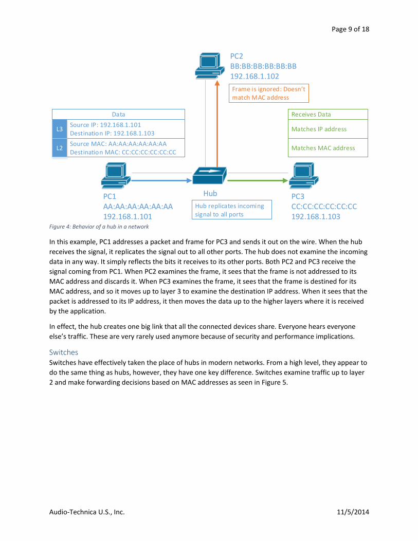
Figure 4: Behavior of a hub in a network
In this example, PC1 addresses a packet and frame for PC3 and sends it out on the wire. When the hub
receives the signal, it replicates the signal out to all other ports. The hub does not examine the incoming
data in any way. It simply reflects the bits it receives to its other ports. Both PC2 and PC3 receive the
signal coming from PC1. When PC2 examines the frame, it sees that the frame is not addressed to its
MAC address and discards it. When PC3 examines the frame, it sees that the frame is destined for its
MAC address, and so it moves up to layer 3 to examine the destination IP address. When it sees that the
packet is addressed to its IP address, it then moves the data up to the higher layers where it is received
by the application.
In effect, the hub creates one big link that all the connected devices share. Everyone hears everyone
else’s traffic. These are very rarely used anymore because of security and performance implications.
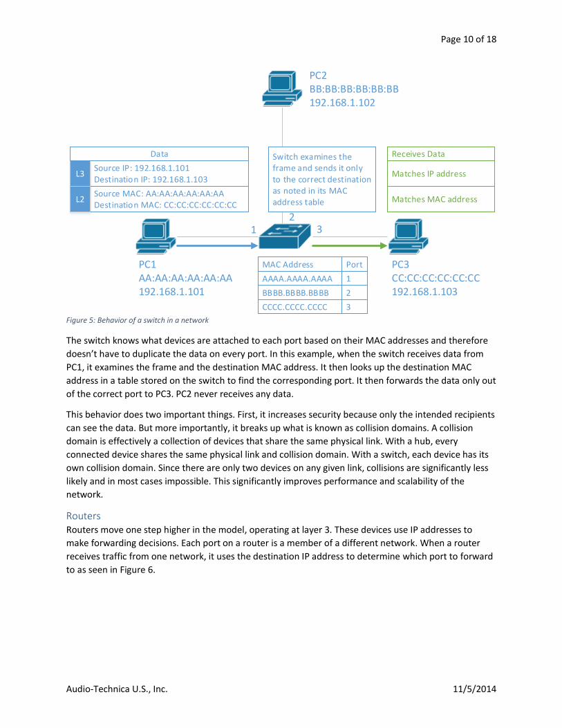
Switches Switches have effectively taken the place of hubs in modern networks. From a high level, they appear to
do the same thing as hubs, however, they have one key difference. Switches examine traffic up to layer
2 and make forwarding decisions based on MAC addresses as seen in Figure 5.
Page 10 of 18
Audio-Technica U.S., Inc. 11/5/2014
PC1AA:AA:AA:AA:AA:AA192.168.1.101
PC2BB:BB:BB:BB:BB:BB192.168.1.102
PC3CC:CC:CC:CC:CC:CC192.168.1.103
Source MAC: AA:AA:AA:AA:AA:AADestination MAC: CC:CC:CC:CC:CC:CC
Source IP: 192.168.1.101Destination IP: 192.168.1.103
L2
L3
Data
Matches MAC address
Matches IP address
Receives DataSwitch examines the frame and sends it only to the correct destination as noted in its MAC address table
AAAA.AAAA.AAAA 1
BBBB.BBBB.BBBB 2
CCCC.CCCC.CCCC 3
MAC Address Port
12
3
Figure 5: Behavior of a switch in a network
The switch knows what devices are attached to each port based on their MAC addresses and therefore
doesn’t have to duplicate the data on every port. In this example, when the switch receives data from
PC1, it examines the frame and the destination MAC address. It then looks up the destination MAC
address in a table stored on the switch to find the corresponding port. It then forwards the data only out
of the correct port to PC3. PC2 never receives any data.
This behavior does two important things. First, it increases security because only the intended recipients
can see the data. But more importantly, it breaks up what is known as collision domains. A collision
domain is effectively a collection of devices that share the same physical link. With a hub, every
connected device shares the same physical link and collision domain. With a switch, each device has its
own collision domain. Since there are only two devices on any given link, collisions are significantly less
likely and in most cases impossible. This significantly improves performance and scalability of the
network.
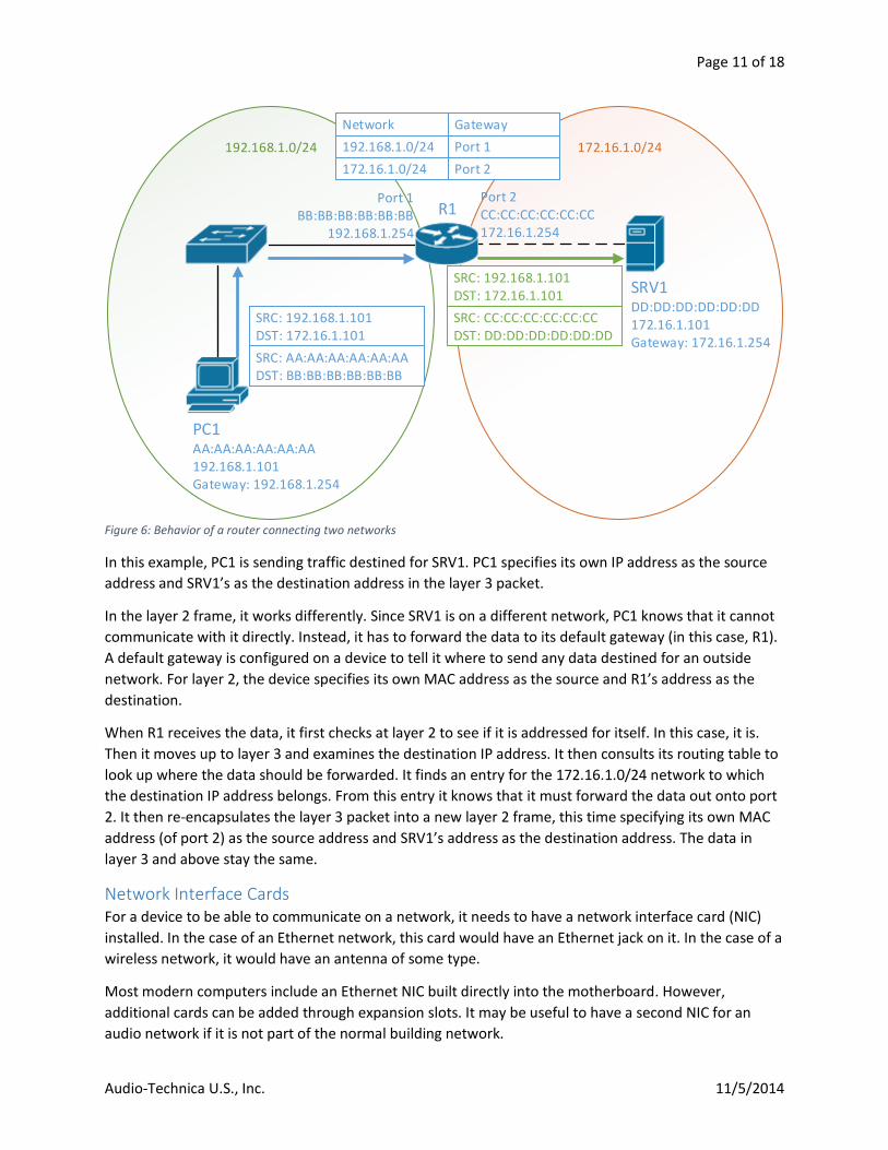
Routers Routers move one step higher in the model, operating at layer 3. These devices use IP addresses to
make forwarding decisions. Each port on a router is a member of a different network. When a router
receives traffic from one network, it uses the destination IP address to determine which port to forward
to as seen in Figure 6.
Page 11 of 18
Audio-Technica U.S., Inc. 11/5/2014
172.16.1.0/24192.168.1.0/24 192.168.1.0/24 Port 1
172.16.1.0/24 Port 2
Network Gateway
PC1AA:AA:AA:AA:AA:AA192.168.1.101Gateway: 192.168.1.254
SRV1DD:DD:DD:DD:DD:DD172.16.1.101Gateway: 172.16.1.254
Port 1BB:BB:BB:BB:BB:BB
192.168.1.254
Port 2CC:CC:CC:CC:CC:CC172.16.1.254
SRC: AA:AA:AA:AA:AA:AADST: BB:BB:BB:BB:BB:BB
SRC: 192.168.1.101DST: 172.16.1.101
R1
SRC: CC:CC:CC:CC:CC:CCDST: DD:DD:DD:DD:DD:DD
SRC: 192.168.1.101DST: 172.16.1.101
Figure 6: Behavior of a router connecting two networks
In this example, PC1 is sending traffic destined for SRV1. PC1 specifies its own IP address as the source
address and SRV1’s as the destination address in the layer 3 packet.
In the layer 2 frame, it works differently. Since SRV1 is on a different network, PC1 knows that it cannot
communicate with it directly. Instead, it has to forward the data to its default gateway (in this case, R1).
A default gateway is configured on a device to tell it where to send any data destined for an outside
network. For layer 2, the device specifies its own MAC address as the source and R1’s address as the
destination.
When R1 receives the data, it first checks at layer 2 to see if it is addressed for itself. In this case, it is.
Then it moves up to layer 3 and examines the destination IP address. It then consults its routing table to
look up where the data should be forwarded. It finds an entry for the 172.16.1.0/24 network to which
the destination IP address belongs. From this entry it knows that it must forward the data out onto port
2. It then re-encapsulates the layer 3 packet into a new layer 2 frame, this time specifying its own MAC
address (of port 2) as the source address and SRV1’s address as the destination address. The data in
layer 3 and above stay the same.
Network Interface Cards For a device to be able to communicate on a network, it needs to have a network interface card (NIC)
installed. In the case of an Ethernet network, this card would have an Ethernet jack on it. In the case of a
wireless network, it would have an antenna of some type.
Most modern computers include an Ethernet NIC built directly into the motherboard. However,
additional cards can be added through expansion slots. It may be useful to have a second NIC for an
audio network if it is not part of the normal building network.
Page 12 of 18
Audio-Technica U.S., Inc. 11/5/2014
Cabling and Ethernet In a wired network, devices are connected together with cabling. In most networks, this cabling is
copper, although network backbones are typically made up of fiber optics.
A standard copper Ethernet cable is made up of eight individual strands of copper. These strands are
twisted into pairs at various rates to reduce interference as much as possible. There are different grades
of cable and the grade determines the speed of network traffic and the maximum length. Corporate
copper networks consist mostly of Category 5 (Cat5), Category 5 enhanced (Cat5e), and Category 6
(Cat6) cable.
Network Speeds Depending on the cabling and the individual devices, a network can support a variety of speeds.
Generally, higher-numbered cable yields higher speeds and longer distances but is thicker or less
flexible. For example, Cat5 cable can only support 100 megabits per second (Mb/s) over a maximum of
100 meters, while Cat5e can support 1 gigabit per second (Gb/s) over short distances. Cat6 can support
full gigabit speeds over a full 100 meters and 10 Gb/s speeds over short distances.
Power over Ethernet Normally, copper Ethernet is only used for transmitting data. However, some devices can also be
powered over the cable, as defined in the IEEE 802.3af standard. Typically this power is enough to
support small devices such as an IP phone or a wireless access point. In the case of Dante, this is
sufficient power to power microphones and some small speakers. The advantage to this technology is
that it uses only a single cable and equipment can be placed in areas where electrical outlets do not
usually exist, such as ceilings.
DHCP The Dynamic Host Configuration Protocol (DHCP) is an application that enables automatic assignment of
IP addresses. Instead of manually assigning IP address to each device, a DHCP server can be put in place
to automatically hand out IP addresses in a configured range. It can also specify options denoting the
location of default routes, name resolution servers, and time servers.
Most home and small office routers include a preconfigured DHCP server so that no configuration is
necessary to get a working network and Internet connection. In a large network, a central DHCP server is
likely to exist.
When a DHCP server does not exist on a network and no IP address is manually configured, a device in
some cases can automatically assign itself a link-local IP address in the range of 169.254.0.0/16. These
addresses can only be used to address devices on the same local network. In the case of Dante devices,
this may be suitable as long as audio does not need to be routed to another network. A self-contained
network of audio devices would be a scenario in which this kind of addressing is sufficient.
VLANs A Virtual LAN (VLAN) is a logical separation of a network into multiple, separate broadcast domains.
Normally, a broadcast domain is only defined by a router. Under this model, each network exists on a
separate switch attached to a port on a router. VLANs allow for these multiple networks to exist on a
switch. Essentially, it breaks up a switch into multiple pieces.
Page 13 of 18
Audio-Technica U.S., Inc. 11/5/2014
Typically, VLANs are only a feature of managed switches. A managed switch is configurable by a user to
do more advanced things than simply switching frames. Each port on the switch can be assigned a VLAN.
Any traffic on that port then belongs to that VLAN. Additionally, a port can also be configured as a trunk
port that carries all VLANs. Trunk links are usually only used between switches. When the switch sends a
frame out on a trunk port, it tags the frame with its VLAN ID so that the switch on the other end knows
what VLAN it belongs to.
In an enterprise network, VLANs are traditionally used to segregate traffic. For example, a separate
VLAN could be created for IP phones, computers, servers, device management, etc. In the case of Dante,
creating a VLAN for audio can help isolate the traffic for security or performance reasons.
Quality of Service Quality of Service is a technology that allows the prioritization of some traffic over another. Due to the
nature of IP-based networks, some packets may take longer to reach their destination than others. This
is usually not an issue for network traffic such as web browsing or file transfers. However, it is a primary
concern for any type of streaming audio or video applications as they are sensitive to latency and jitter.
Latency is the time it takes a single packet to reach its destination after it is sent. Typically, this is
expressed in milliseconds (ms). On a local network, latency will be close to or under 1 ms. Over the
Internet, latency could jump to as high as 500 ms or even higher. In the case of live audio, minimal
latency is critical.
Jitter is the variance in latency for a group of packets to reach their destination. If one packet takes 1 ms
to arrive and another takes 3 ms, the jitter in that case is 2 ms. High jitter can cause audio to break up or
stutter as some packets don’t arrive in time.
Prioritizing voice and video traffic will ensure that it always is first in line to be switched and/or routed.
This ensures minimal latency and jitter. To differentiate the priority needs of different types of traffic,
devices on the network can mark a priority level on their traffic.
Basic Network Configuration A basic Dante network does not require complex configurations to operate. If the only requirement of
the network is to run Dante devices, such as in a test environment, setup can be as simple as the Dante
devices themselves, a PoE switch, and a PC as a controller. In a larger deployment, where the existing
network infrastructure will be used, configuration may be necessary in order to coexist nicely with other
traffic.
Configuring Network Equipment If all of the switches that will be used to connect Dante devices and any switches in between are all
connected with layer 2 trunk links, the simplest way to separate the traffic would be to create a
separate VLAN just for the audio devices. This keeps all of the devices on the same subnet and keeps
non-audio traffic off the audio network.
If all of the audio devices are not able to be connected to the same subnet, routers in the network will
need to be configured to forward multicast traffic so that the devices can discover each other across
network boundaries.
Page 14 of 18
Audio-Technica U.S., Inc. 11/5/2014
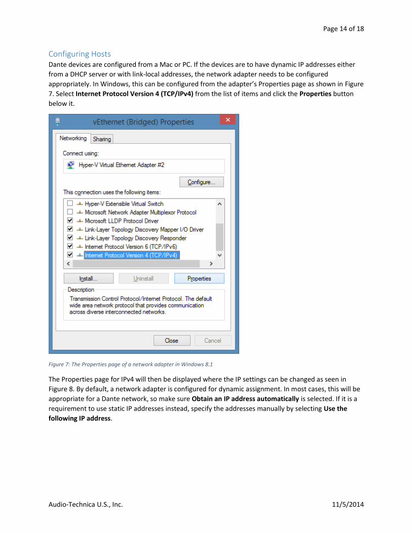
Configuring Hosts Dante devices are configured from a Mac or PC. If the devices are to have dynamic IP addresses either
from a DHCP server or with link-local addresses, the network adapter needs to be configured
appropriately. In Windows, this can be configured from the adapter’s Properties page as shown in Figure
7. Select Internet Protocol Version 4 (TCP/IPv4) from the list of items and click the Properties button
below it.
Figure 7: The Properties page of a network adapter in Windows 8.1
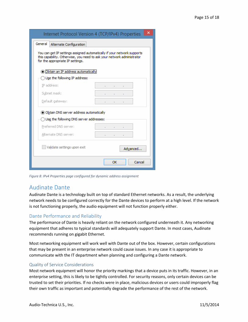
The Properties page for IPv4 will then be displayed where the IP settings can be changed as seen in
Figure 8. By default, a network adapter is configured for dynamic assignment. In most cases, this will be
appropriate for a Dante network, so make sure Obtain an IP address automatically is selected. If it is a
requirement to use static IP addresses instead, specify the addresses manually by selecting Use the
following IP address.
Page 15 of 18
Audio-Technica U.S., Inc. 11/5/2014
Figure 8: IPv4 Properties page configured for dynamic address assignment
Audinate Dante Audinate Dante is a technology built on top of standard Ethernet networks. As a result, the underlying
network needs to be configured correctly for the Dante devices to perform at a high level. If the network
is not functioning properly, the audio equipment will not function properly either.
Dante Performance and Reliability The performance of Dante is heavily reliant on the network configured underneath it. Any networking
equipment that adheres to typical standards will adequately support Dante. In most cases, Audinate
recommends running on gigabit Ethernet.
Most networking equipment will work well with Dante out of the box. However, certain configurations
that may be present in an enterprise network could cause issues. In any case it is appropriate to
communicate with the IT department when planning and configuring a Dante network.
Quality of Service Considerations Most network equipment will honor the priority markings that a device puts in its traffic. However, in an
enterprise setting, this is likely to be tightly controlled. For security reasons, only certain devices can be
trusted to set their priorities. If no checks were in place, malicious devices or users could improperly flag
their own traffic as important and potentially degrade the performance of the rest of the network.
Page 16 of 18
Audio-Technica U.S., Inc. 11/5/2014
As a result, in most corporate networks, a corresponding configuration needs to be made on network
equipment to trust these priority markings. If these configurations are not made, the Dante devices
could experience higher than normal latency or jitter, causing audio degradation or dropouts. Even if all
the devices are on a separate VLAN, they still need to be given priority so that their traffic is switched
ahead of less critical applications. The actual configuration steps are dependent on the vendor of the
network equipment as well as the environment and should be performed by IT staff.
Congestion and Bottlenecks Congestion on a network occurs when a link reaches 100% capacity. Once at capacity, any additional
traffic will wait in a buffer until there is room for it on the link. If the buffer fills up, traffic will start to be
dropped. In the case of Dante, this could cause dropouts if audio traffic is being dropped.
The most common source of congestion is uplink ports between switches. For example, if 20 devices
connected to a switch are each sending traffic at 100 Mbps and that traffic needs to be switched over a
1 gigabit uplink, congestion will occur because there is a total of 2 Gbps of traffic.
Security Dante is easy to use by design. Any computer running the Dante controller is able to discover Dante
devices on the network and reroute audio. While this makes the setup very simple, it presents a security
concern as unauthorized users could potentially mess up the network or eavesdrop on communications.
As a result, it is important to properly isolate Dante traffic from the rest of the network using VLANs,
much like when optimizing for performance.
Troubleshooting Generally, most problems with Dante are caused by a problematic network underneath. There are a
variety of methods to troubleshoot a network, but most administrators take a structured approach
based on the OSI model. When an issue occurs, they will step through each layer until they find the
problem. Typically, they will start at the physical layer and work up or start at the application layer and
work down. Sometimes it may also be appropriate to start in the middle and split the model, working up
the layers on one half and down the layers on the other.
Layer 1 Problems at the physical layer usually are a result of faulty cabling. For example, if the link lights on the
back of a network card don’t come on, the problem is physical and could either be a bad cable, a faulty
or disconnected network card on one end, or a port disabled on a network device.
To ensure that layer 1 is functioning as expected, physical connectivity must be ensured between every
link between devices.
Layer 2 At the data link layer problems usually result from the misconfiguration of network equipment. For
example, if two devices are configured to belong to the same network, but their ports on the switch are
configured to be in separate VLANs, communication won’t be successful. Additionally, if the devices
exist on different switches but are configured on the same VLAN, that VLAN must be allowed to traverse

Page 17 of 18
Audio-Technica U.S., Inc. 11/5/2014
a VLAN trunk link between the switches. If a VLAN isn’t able to be trunked as it should be,
communication will fail6.
At layer 2, successful communication can be verified by ensuring communication is possible between
devices on the same subnet. If the device is running a full operating system such as Microsoft Windows
or is a network device that can be managed, the ping utility can be used to test connectivity. The ping
utility utilizes the Internet Control Message Protocol (ICMP) echo command to send a request to a
remote device that will respond with an echo reply7. The basic syntax of the ping command is simple, as
seen in Figure 9. In most devices, the command is followed only by the IP address of the remote host.
Figure 9: Example of the syntax and successful output of the ping command when run from the Command Prompt on Windows
Layer 3 At the network layer problems result from routing issues. If two devices are in separate subnets, a
router must exist between the devices to route the traffic between networks. Routing issues can be
caused by mistyped IP addresses or subnet masks as well as by missing routes in a device’s routing table.
A device only knows about the networks that are defined in its routing table. For an end device like a
Dante microphone or a desktop computer there is a route for the local network and a default route if
configured. A default route is simply a route for the 0.0.0.0/0 network that points at a router on the
local network, known as the default gateway. This causes any traffic not destined for the local network
to be forwarded to the default gateway. Routers are more complex in that they maintain a table of
many more routes. If there are multiple routers in a network, they must all know about the others’
routes. Typically, if a device cannot reach a host in a remote network, the problem is with a router’s
routing table.
Layer 4 At the transport layer communication problems are usually the fault of a firewall. This can be either the
firewall that exists on a PC or an appliance that exists on the network between the devices. A firewall
will block traffic on ports to mitigate possible attacks. If it blocks a port that is needed by an application,
6 A variety of other technologies can cause problems at layer 2, including Spanning Tree Protocol (STP) as well as link aggregation. These technologies are beyond the scope of this document. 7 In some corporate networks, ICMP may be filtered by the network or disabled on the remote device.
C:\Users\Administrator>ping 172.16.1.1 Pinging 172.16.1.1 with 32 bytes of data: Reply from 172.16.1.1: bytes=32 time<1ms TTL=128 Reply from 172.16.1.1: bytes=32 time<1ms TTL=128 Reply from 172.16.1.1: bytes=32 time<1ms TTL=128 Reply from 172.16.1.1: bytes=32 time<1ms TTL=128 Ping statistics for 172.16.1.1: Packets: Sent = 4, Received = 4, Lost = 0 (0% loss), Approximate round trip times in milli-seconds: Minimum = 0ms, Maximum = 0ms, Average = 0ms

Page 18 of 18
Audio-Technica U.S., Inc. 11/5/2014
that application may break. To troubleshoot communication at layer 4, make sure that any firewalls
between two devices are configured to allow the necessary ports.
Layers 5, 6, and 7 Problems above layer 4 are usually a result of the application itself. In rare instances, firewalls that do
deep inspection into network traffic may be the culprit, but problems are normally a fault of the
program.