networked futures || advanced optical fibre networks
TRANSCRIPT

Advanced Optical Fibre Networks
THE NEED FOR FAST BIT TRANSMISSION - SOME SCENARIOS
Suppose every evening, one million people decide to select a film or TV programme of their choice, at a time of their choosing. We could imagine the programme material stored on stacks of disks that are connected to the network and called down, ‘on demand’. Everyone must be supplied individually with a bit stream which will run at a minimum of 2 Mbit/s, if they are to receive high-quality images and sound. That is a demand for 2 million million bits every second. This is at least two orders of magnitude greater than today’s total tele- phone traffic for the UK.
Consider another scenario: medical diagnosis. Modern medicine is impressive, but expensive and rapidly becoming even more so. The UK spends some 5% of GDP on healthcare, these costs having tripled in the last three decades. It is impossible to provide full healthcare just exactly where it is needed. But it is possible that the difficulty of access to specialist consultants - which previously led to a cost equivalent to six times their salary - can be solved by providing wideband con- nections between them and the medical team in the patient’s local hospital. Initially, a simple X-ray is carried out. Even for this, the data consists of about 10 Mbytes per image, and several are needed. These are sent over the network to the remote consultant. She needs more information, a CAT scan, NMR, PET, ultrasound, endoscopy and so
Networked Futures: Trends for Communication Systems DevelopmentW.S. Whyte
Copyright © 1999 John Wiley & Sons, LtdISBNs: 0-471-98794-8 (Hardback); 0-470-84185-0 (Electronic)

84 NETWORKED FUTURES
on. They all require more and more data to be transmitted and their resolution is increasing every year. The ultimate desire is to be able to examine ’slices’ of the body continuously rotating through any angle and at resolutions of surgical precision. The standard methods of compressing images onto limited-speed networks are not the answer: smoothing and sharpening images and error concealment are only acceptable provided they do not create artefacts or hide real problems. In any case, the analysis equipment itself is very expensive and cannot always be located close to the patient. What is required is a cheap ’head-end’ that is sufficient to capture the necessary information and transmit it, probably uncompressed and unanalysed, to the centre, with a backward channel to allow the consultant to control the scan.
There is no reason in principle why remote healthcare should be restricted to examination. Surgery no longer relies solely on ‘hands- on’ movement of a scalpel. For instance, robot surgeons have demon- strated a performance superior to that of humans, when drilling bone. Precision cutting can be achieved over a distance, under the control of an expert. But here there is a very real problem with data compression: it has an inherent need to process over several images, leading to a delay. In general, the greater the bit reduction, the longer the buffer of stored data. That is, the longer the delay between the act and its image at the far end! The implications of this cut deep into remote surgery, quite literally.
So we have accepted that bandwidth requirements for remote healthcare will require considerable care and there is a need to err on the side of caution. We also have to note that images are not sent just once. They may do the rounds of several experts in several locations. They have to be stored for a number of years (21 for newborn children in the UK) and reliably accessed. Undoubtedly any attempt to quantify the amount of data required will result in an underestimate.
WHY DO WE NEED OPTICAL NETWORKS?
We need optical networks because our requirement for information transmission grows without bounds and optical networks are the only means of providing it economically. Ever since the beginning of telephony, the market has been driving technology faster and faster to find the answer. Pairs of copper wires gave way, in the 1950s and 60s, to coaxial tubes, but even their capacity reaches a practical limit of a few hundred megabits in the main (inter-exchange) network, and a

ADVANCED OPTICAL FIBRE NETWORKS 85
real crisis of capacity arises in the local network between individuals and their first exchange, where use of flexible coaxial cable or twisted copper pairs of wires restrict it to a few tens of megabits per second. The solution to this bottleneck has been the invention of low-loss optical fibre. Not only does fibre provide a solution without equal for long-distance transmission, its low cost and small size offer an option that can revolutionise the 'last mile' between the local telephone exchange and the customer, where high bit-rate delivery had always been problematic.
THE EVOLUTION AND REVOLUTION OF OPTICAL NETWORKS
Since the 1980s, the infiltration of optical fibre into telecommunica- tions networks has become an established fact. There are millions of kilometres of fibre installed in the world today (at least 1.5 million in the UK and over 10 million in the USA), and fibre is the preferred option not only for all new inter-exchange connections, but also for multiple business lines and, in some cases, for street cable TV networks.
However, despite the major economic and reliability improvements brought about by the introduction of optical fibre technology, the change has been incremental rather than radical. Fibres take up less room and require less line-plant, but today they still carry signals that have essentially the same structure as those formerly carried on copper: they use digital pulse techniques designed to meet the limita- tions of copper cables; they require all 'intelligent' functions such as switching and even something as basic as amplification and regenera- tion (reshaping) of the digital pulses to be carried out in the electrical, rather than optical, domain. This 'copper mind-set', as it has been described, abandons an enormous amount of the potential that could be realised from an (almost) 'all-optical network' that is based on its own capabilities rather than the limitations of its predecessors. It is instructive to speculate on the implications if we were able to design a radically new network architecture based on the properties of fibre alone.
Centralised Switching
In Chapter 2, we explained the existence of telephone exchanges as a way of avoiding the need to connect everyone to everyone else by a

86 NETWORKED FUTURES
separate pair of wires, leading to around one billion pairs of wires running into each house in a country the size of Great Britain. This architectural constraint is the reason why, despite the dramatic change in the volume and nature of traffic, there has been a 'magic number' of 600 telephone exchanges for many decades. The enormous carrying capacity of fibre means that this constraint can be removed and we can begin to think of reducing significantly the number of exchanges, as well as greatly simplifying the way they operate.
Time-domain Multiplexing
It is possible to multiplex several individual channels onto one pair of wires, coaxial cable or optical fibre. Early methods of multiplexing several speech signals onto one cable relied on 'frequency division multiplexing' (explained later in this chapter). The development of cheap and reliable digital circuitry in the 1960s and 70s led to the demise of frequency division multiplex in favour of 'time division multiplex', where the speech signals were digitised and the bytes from multiple channels transmitted in time sequence, one after the other (see the frame on time division multiplexing in Chapter 2). There is a problem with time division multiplexing: suppose we have N calls, each of 64 Kbit/s, on a single cable coming into a switch and we wish to switch them to different outlets, for onward transmission. Then the switch must be able to make a switching decision at the aggregate bit-rate of N X 64 Kbit/s. Thus, the ultimate speed of operation of a communication system may become limited by the achievable speed of the switch, not by the transmission cable. Currently, affordable digital electronics reaches its maximum at a few Gbit/s. As the demand for higher rates increases, we have to look for alternatives to the copper-based time division multiplex principle. Again, the capacity of fibre comes to our rescue, allowing a simpler switching structure with lower speed requirements.
Capacity Problems
We have explained that networks of the future will have to provide a multiservice capability: that is, they will need to handle voice and image with a guaranteed minimum bit-rate and a limit to the maximum end-to-end delay, at the same time as being able to cope with bursty data. To achieve all of this on limited capacity networks has required the construction of numerous transmission protocols,

ADVANCED OPTICAL FIBRE NETWORKS 87
many of which are incompatible or can interwork only with difficulty. To make the transmission networks affordable, we have seen how telephony and computing data must be squeezed into the system using statistical multiplexing techniques such as ATM.
But, however we try, whenever the maximum capacity of the channel is lower than the theoretical sum of the individual data streams, sooner or later there is going to be unsatisfied demand. The theoretical carrying capacity of fibre removes this problem, at least on national cable routes. (Granted there will always be some areas where this is a problem, for example with already installed copper cables, satellite or local wireless systems, but it would be a pity to spoil the attractive simplicity of ATM, where it was not necessary.)
Electronics
Today’s optical fibre systems are more truly ’electronic’ than ’optical’. All multiplexing, amplification and switching is done by operating on electrical signals, either before they are converted to light, or after they have been converted back to electricity, or even by conversion from optical to electrical and back again, in mid-path. Obviously, this is expensive and potentially unreliable. There are special problems in hostile environments, particularly the local loop between the customer and the first exchange. Here there is an additional problem: how to provide reliable power supplies to drive any complex equipment that must be housed in a street cabinet or an underground cable chamber.
A NEW ARCHITECTURE
If we were to consider throwing away all the architectural constraints of a network architecture which has its roots in the properties and limitations of copper, and build a network based on the full potential of optical technology, in what way would it be different? We look first at the traditional, copper-based network, as shown in Figure 3.1.
Consider what is required in communicating between A and G: A to B and F to G traverse rather low-quality copper pairs of wires dedicated to the individual customer. From B to C (a main switching centre) the path may well be optical fibre, but ’playing by copper rules’: for instance, the signal from A is first electrically combined with other signals, using time division multiplex. At C, D and E the signal is again converted to electrical form and switched electronically

88 NETWORKED FUTURES
1 D
B
Figure 3.1 ‘Traditional’ network
to the correct path, over a cable which is probably fibre. Bit-rate bottle- necks occur at various points in the network: there are customer to local network connections at a few hundred Kbit/s, unless special cable or transmission techniques are used; there is a switching bottle- neck at the various exchanges; and there is a possibility of temporary loss of service at links served by statistical multiplexors.
Compare this with the case of the ’ultimate’ optical network (Figure 3.2). A is provided with a full bit-rate, very fast, instantly available connection to B, C and D across their local optical networks and across an optical backbone without any tapering of the transmission capability, without any other loss of performance or complicated switching. The network becomes closer to a bus or a ring than to a tree with branches and roots. That is its logical form. Physically, it may be constructed quite differently, and in any case what we have shown is the ideal, ultimate, all-optical network, for which the technology is not yet quite there. But in the sections that follow, we shall show that realisable networks are coming quite close to that ideal. They retain some elements of the past: there is still a need for some centralised switching and we still make use of time division multiplexing, where it does not restrict performance; but, overall, we shall see how the prospect of virtually infinite carrying capacity sets us free from nearly all of the constraints.
Backbone
A D B C
Figure 3.2 The ’ultimate’ optical network

ADVANCED OPTICAL FIBRE NETWORKS 89
OPTICAL DIMENSIONS
Although the same basic building blocks are used in all communica- tions systems, the way they operate depends on the technology deployed. Optical devices obviously operate using 'light'. Light is an electromagnetic wave phenomenon, just like wireless and, for that matter, electrical signals in coaxial cables and wires. We know that waves spreading out from a point are able to bend round obstacles in their path and interfere with other waves to build up into larger amplitudes or to cancel each other out. Our everyday experience teaches us, however, that light, wireless signals and basic voice telephone wires each behave in very different ways. Telephone wires do not radiate our telephone conversations into adjoining pairs of wires. That is, they are poor aerials, whereas quite short wires can be used for transmitting radio or TV signals. Radio signals bend round buildings but light appears to travel in straight lines. Optical fibres do not experience any induced noise. 'These differences come about because the wavelengths of each of their waves are of very different size. Consider the basic relationship connecting wavelength, velocity of propagation and frequency, shown in Figure 3.3.
The velocity of light in vacuum, copper cables or fibre is quire similar in all cases. In vacuum it is 300 000 000 m/s. In optical fibre it is about 50% less, and it is about one-third as great in copper cable. Let us look at the wavelengths of typical signals in each of these media.
Speech, directly converted to electrical signals by a telephone microphone, has a significant frequency content of around 3000 Hz, if treated thereafter as an analogue signal, or about 60 000 Hz if con- verted to digital form. (See the Appendix, Chapter 11, for the justifica- tion for this figure.) Therefore, the wavelength of speech signals
wavelength= x
c = velocity of light x = c/f f = frequency in Hz (cycles/second)
Figure 3.3 Basic parameters of a wave

90 NETWORKED FUTURES
carried in this direct form over a copper cable is of the order of 1 km (100 000 000/60 000 m).
In radio systems, the 60000 Hz bandwidth is of little relevance to the behaviour of the radio wave, because the speech is 'modulated' onto a very high frequency 'carrier' (see frame). The highest carrier frequencies used in free space transmission between radio towers or from satellites are of the order of 30 GHz (30 000000000 Hz). This corresponds to a wavelength of 300 000 000/30 000 000 000 = 1/100 m.
Optical fibre systems use modulated beams of light to carry the signal. The light has a frequency of the order of 300 000 000 000 000 Hz, corresponding to a wavelength of 1/1000 000 of a metre, usually referred to as 1 micron. (In fact, because the frequency is so high, it is usually more convenient to discuss optical systems in terms of their wavelength.)

ADVANCED OPTICAL FIBRE NETWORKS 91
So, we see that optical wavelengths are of the order of 1/10 000 of the size of the highest usable radio waves and 1 /l 000 000 000 that of the wavelengths of the original, ’baseband’ signal. Two very important consequences result from this:
0 Wave phenomena occur at a much smaller scale - the basic dimension that determines whether waves will bend round obstacles, interfere with each other, penetrate the surface of materials, and so on, depends not on the absolute distance in metres but on the ratio of the distance to the wavelength. An aerial must be a significant fraction of a wavelength in order to radiate well - that is why baseband, twisted pair, speech cables (each of whose twists creates aerials of a fraction of a metre) do not interfere significantly with each other. Long-wave wireless can ’bend’ round tall buildings and even mountains, when the aerial is out of the line of sight. On the other hand, cellular radio and satellite systems, operating at GHz frequencies, make use of the fact that their area of operation is effectively line-of-sight; their signals can be obscured by obstacles a metre or so in dimension. To an optical system, a metre is a million wavelengths; optics concerns itself with dimensions of the order of the track widths of silicon integrated circuits. Optical components have ’aerials’ that are a few microns in size. Beyond this distance, light does not really behave like a wave; it travels in ’rays’, or at least we can frequently use the ray as a simple but adequate way of analysing optical systems.
0 Channel capacity is related to carrier frequency - we discussed how the basic data we wish to transmit is frequently ’modulated’ onto some form of carrier. The carrier is thus deviated from its normal value by the data. Clearly, the rate of variation of the carrier is directly related to the data-rate of the basic information modulated onto it. For some fairly fundamental reasons, it is a reasonable approximation to say that the achievable rate of variation of the carrier is proportional to the carrier’s normal frequency. That is, the data-rate achievable on any carrier system is proportional to the carrier fvequency. This is of obvious significance when we realise that the optical ‘carrier’, that is, light, has a frequency that is of the order of 10 000 times that of the highest usable radio frequencies.
OPTICAL COMPONENTS
The component parts of any telecommunications system are, at basics, similar irrespective of the technology used:

92 NETWORKED FUTURES
0 We must have some medium for transmitting the signal without too much loss, over the required distance. In the optical case, this is an opticalfibre.
0 We need devices at either end that can generate and receive the signal, converting to and from the mode used for transmission and that required locally (for instance, sound waves to electricity). In the optical case, these are respectively laser diodies and photodiodes.
0 There must be a way of routing the signal through the network so that it goes to the right place and does not interfere elsewhere with signals destined for other receivers. Optical systems will make use of components such as optical splitters, couplers andfilters.
We now consider these elements in more detail.
OPTICAL FIBRES
The basic principle of optical fibre transmission is very simple, as can be seen from Figure 3.4.
If we have an interface between two transparent media, such as two glasses, which have different refractive indices (i.e., light travels at different velocities in them) and a ray of light passes from the medium with the higher refractive index, M,, to the lower, n2 (i.e. from the lower velocity to the higher), then the ray in n2 will emerge closer to the interface than it was in n,. If we make the angle in n, sufficiently
~-
Figure 3.4 Principles of fibre transmission

ADVANCED OPTICAL FIBRE NEWORKS 93
small, then the ray will be bent so far back to the interface that it will never really pass into n2. Making it even smaller means it will be totally internally reflected within nl at the same angle as it hit the interface. Optical fibres possess this dual refractive index and have a core (index n l ) which is so fine, typically of the order of 10 nm across, that any light launched into the core, by a laser or light-emitting diode, will enter at such a small angle that internal reflection will always occur.
If we combine this dimensional property with the additional requirement that the glass be manufactured in such a way that it is chemically very pure and free from imperfections, then the glass itself will not absorb much of the light and we can also get a fibre with very low loss of light over long distances.
FIBRE PERFORMANCE: LOSS AND BANDWIDTH
Figure 3.5 puts some values to the attenuation and wavelength range for fibre. The smoothness of the curve hides the dramatic progress that has been made over the past two decades in moving the overall curve downwards and in removing some major 'bumps' in it, particu- larly at 0.9 and 1.4 micron, where resonant absorption can occur be- cause of water molecules trapped in the glass during manufacturing.
Converting this loss to a range in kilometres is rather complex, involving as it does a number of parameters: operating wavelength,
percentage of signal lost after 1 km
0.8 1.5 2.0 wavelength (microns)
Figure 3.5 Attenuation per kilometre in optical fibre

94 NETWORKED FUTURES
bit-rate, performance of optical transmitters and receivers and, of course, the fact that long cables will inevitably require splicing, with significant fractions of transmission loss. However, with current tech- nologies, it is easily possible to send signals over distances of hundreds of kilometres, without any amplification. In any case, as we shall see, there are ways whereby we can extend this range indefinitely, without requiring to convert from an optical signal back to an electrical one.
In practice, not all of this range of wavelength will be used, for there are some more subtle issues of fibre performance and there are re- stricted optimum ranges for the semiconductor transmitters and receivers that operate at the ends of the fibre. There are three particu- larly good regions of operation centred on 0.85 micron, 1.3 micron and 1.5 micron. Around each of these regions is about 25 000 GHz of bandwidth (approximately equivalent to a potential transmission bit- rate of at least 25000 Gbit/s. That is much more than the total telephone traffic carried in the UK today. The fastest metallic cable, a rigid and heavy coaxial cable, operates at only a few tens of MHz over distances of tens of kilometres. The entire radio spectrum available is somewhat less than 30 GHz. The sudden availability of 25000 Gbit/s on a single fibre cannot be dismissed as a mere incremental improvement.
If that were not all, there are number of other bonuses: by its very nature, fibre provides a very reliable and noise-free medium. Unlike wire pairs or even coaxial cable, there is no chance for interfering signals to be impressed onto the legitimate one. We can design end-to- end systems on the assumption that the optical path will be error-free. This leads to considerable simplification in terminal equipment and also in reducing system delay brought about by the need to carry out error checking and, possibly, resending of data. At the operational level, there are advantages too: fibre is considerably lighter, thinner and more flexible than its copper rivals; cable technology now ensures that it can be protected against damage and easily jointed or termin- ated without introducing significant losses. Thus, of the optical components required to create a transmission system, we can say that fibre will not be the one that limits the performance.
TRANSMITTERS AND RECEIVERS
The detailed theory of optical transmitters and receivers is extensive and complex. Receiver design is particularly complicated, but the basic optical detectors do not impose, at least in principle, any critical con-

ADVANCED OPTICAL FIBRE NETWORKS 95
straints on the overall performance of an optical network. Transmitters are more of a problem and we shall give a brief outline of the issues involved.
Transmitters in large-scale networks are invariably solid-state lasers, made from semiconductor material. This ensures that they are physically robust, reliable and relatively insensitive to temperature. Laser operation is required in order to obtain sufficient power and to produce light of a sufficiently narrow spectrum.
The phenomenon of ’lasing’ is a result of a quantum-mechanical effect resulting when energy of the right frequency has been injected into the material and raises some of its electrons to enhanced energy levels. Under these conditions, a photon of light of the correct wave- length passing through the material can interact with one of the electrons and cause it to give up its extra energy, which is released as a photon with the same wavelength as the incoming photon. Thus light is amplified.
Obviously the semiconducting material is transparent (since light must travel through it in order to react with the electrons) and some of the light will leak out the ends of the device. But suppose we arrange for the ends of the device to be treated so they behave like partial mirrors; then some of the light is reflected back into the bulk of the material, and again stimulates the electrons to emit light of precisely the same wavelength, all over again. The more this is repeated, that is, the better the reflectivity of the mirrors, the narrower (or ’purer’) becomes the bandwidth of the light emitted.
At this point we must distinguish carefully between two aspects of the laser’s performance: its speed of operation, and its ability to operate over a range of wavelengths.
Speed of Operation
This is a measure of the maximum bit-rate that the laser can transmit/ We might at first think that this was simply the speed at which the laser can be turned on and off, in response to the pattern of bits to be sent, but in fact this is not a very suitable mode of operation. We men- tioned that the repeated passage of light back and forward between the mirrored ends of the laser was required in order to set up the condition for lasing in a narrow frequency range. Switching on and off the laser brutally upsets the purity of the light output. Instead, we have to choose a less disruptive mode of impressing the digital signal onto the laser.
96 NETWORKED FUTURES
laser
main current source -@- electrical data signal
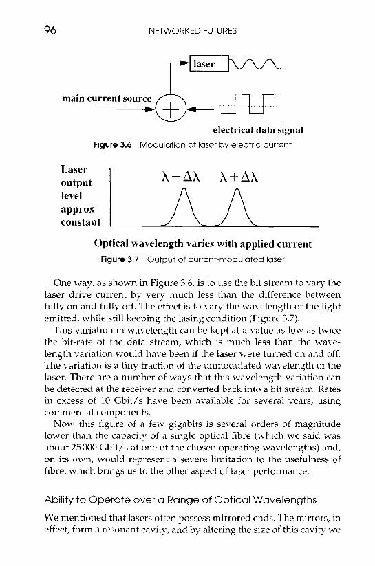
Figure 3.6 Modulation of laser by electric current
X+Ah Laser output level approx constant
Optical wavelength varies with applied current Figure 3.7 Output of current-modulated laser
One way, as shown in Figure 3.6, is to use the bit stream to vary the laser drive current by very much less than the difference between fully on and fully off. The effect is to vary the wavelength of the light emitted, while still keeping the lasing condition (Figure 3.7).
This variation in wavelength can be kept at a value as low as twice the bit-rate of the data stream, which is much less than the wave- length variation would have been if the laser were turned on and off. The variation is a tiny fraction of the unmodulated wavelength of the laser. There are a number of ways that this wavelength variation can be detected at the receiver and converted back into a bit stream. Rates in excess of 10 Gbit/s have been available for several years, using commercial components.
Now this figure of a few gigabits is several orders of magnitude lower than the capacity of a single optical fibre (which we said was about 25 000 Gbit/s at one of the chosen operating wavelengths) and, on its own, would represent a severe limitation to the usefulness of fibre, which brings us to the other aspect of laser performance.
Ability to Operate over a Range of Optical Wavelengths
We mentioned that lasers often possess mirrored ends. The mirrors, in effect, form a resonant cavity, and by altering the size of this cavity we

ADVANCED OPTICAL FIBRE NETWORKS
data rate say I O Gbit/s
I I
I modulation I I I I
say 10-20 GHz I
I - I
I - l I allowance for laser frequency drift I
I and receiver selectivity say l +
I l
I I
97
I I I I
I l l
I I I l l
I I I l l I l l
I I I l l
several hundred individual optical channels
total available bandwidth in an optical window, say 25,000 G H ~
Figure 3.8 Capacity of U single fibre system
can alter the precise wavelength of the light emitted. By this means, or by other methods involving changing the dominant electron energy level or by altering the temperature, we can equip ourselves with a number of lasers operating at different wavelengths and use them over the same fibre.
As we can see from Figure 3.8, in practice we can space out the wavelengths of a few hundred lasers to allow them to operate without overlapping, in any one of the three 25000 Gbit/s optical windows. (We would usually restrict ourselves to one of the windows.) Thus, as a ball-park figure for the best efforts to date, we can say:
one fibre system = 200 to 300 >: 10 Gbit/s = 2000 Gbit/s
Purists will argue about this figure, mainly in the direction that it is too low, but the exact value is not important. What is important is the realisation that this is the performance of a complete and realisable system, not just the theoretical ability of fibre. This is a simple system that operates only in a 'point to point' mode without any means of switching from one optical channel to the next. However, it acts as the basic building block for more complex systems and, as such, is worth looking at in more detail.

98 NETWORKED FUTURES
POINT-TO-POINT WAVELENGTH DIVISION MULTIPLEX
As was said at the beginning of this chapter, there are millions of kile metres of optical fibre in service today, but they are almost exclusively making use of copper technology. In particular, they use time division multiplexing (TDM) to combine data channels, represented in electrical form, and then use this electrical signal to control a laser. An alternative would be to use a separate laser for each of the data channels, each operating at a different optical wavelength, and inject the separate optical signals onto the same fibre. At the other end, optical filters (see later) are used to direct the signal to the appropriate receiver. This tech- nique, of carrying different signals separately over different wavelengths of light, is known as 'wavelength division multiplex'. Simple as it seems, it is the secret to low-cost, ultra-high-bandwidth, global networks.
Figure 3.9 shows the system in more detail, for the case of three sep- arate data channels. (In general, there would be considerably more.) Each of the channels is assigned to a laser working at a different optical wavelength (wl, w 2 , wj). The channels are combined onto one fibre using an optical wavelength division multiplexor, which we shall de- scribe later, and demultiplexed at the far end in a similar manner. Note that a single fibre can carry signals in both directions simultaneously, although on long-haul links it is sometimes preferable to use two fibres, one for each direction, as this makes amplification easier.
TWO TYPES OF MULTIPLEXING
At this point, we ought to look carefully at our use of the term 'multi- plexing', for it occurs in two very distinct ways: optical multiplexing and electrical multiplexing.
W 1 W 2 W 3
W 1 W 2 W 3 =€
wavelength multiplexot-/ demultiplexol
=E wavelength multiplexor/ demultiplexor
Figure 3.9 Wavelength division multiplexing

ADVANCED OPTICAL FIBRE NETWORKS 99
In the previous paragraphs we described how multiple channels could be provided on the same fibre by choosing lasers and filters that operated at different optical wavelengths. These we said could handle signals of several Gbit/s, and we could have several hundred simul- taneous, independent channels each of this bandwidth. Because the independence of the channels is provided by purely optical separation on the basis of wavelength, this is the reason for the name 'wave- length division multiplex'. This term will be used only when the means of multiplexing is optical.
Of course, most times we may not have sources which require individual channels with bit rates of several Gbit/s; instead, we may have multiple channels of lower bit-rates, for example reasonably good-quality video links at 2 Mbit/s. It may be convenient to multi- plex a number of these, electrically rather than optically, into streams that run at the maximum speed that can conveniently be handled by electronics, i.e. a few Gbit/s. We could do this using digital time division multiplexing, as shown in Figure 3.10.
Or we could use the perhaps simpler method of frequency division multiplexing, where the bit streams A, B and C are each modulated onto a different radio frequency carrier, which shifts their signals into non-overlapping parts of the radio spectrum, before the composite signal is converted from electrical form to optical, by the laser (Figure 3.11). Demultiplexing the signal at the other end is quite straight- forward (Figure 3.12): the signal is converted from optical to electrical, filtered to select only the frequency band of interest and then each band demodulated using conventional radio techniques.
Frequency division multiplexing is particularly interesting, because it was the predecessor to time division multiplexing on copper cables but gave way to the latter because, among other reasons, the noisiness
Electrical S I P I I O I S
Figure 3.10 (Electrical) digital time division multiplexing

100 NETWORKED FUTURES
electrical signal
F2
optical signal
4 F3
Figure 3.1 1 (Electrical) frequency division multiplexing
optical signal
electrical signals
filter 1 c
filter 2
F2 filter 3
F3
Figure 3.12 (Electrical) frequency demultiplexing
and long-distance attenuation of copper made it difficult to maintain signal quality with FDM. These are not problems with fibre and, maybe, there will be a resurgence of this technique.
OPTICAL COUPLING
We mentioned that the light from the three lasers was 'coupled' into the fibre. There is a need for another class of optical devices, 'couplers'. These can be formed in a number of ways, but most of them are variations on the theme of 'evanescent field' devices: it is only an approximation to say that light is entirely carried by total internal reflection within the 'core' (the glass with index nl). In fact, a more detailed analysis of the propagation proves that there exists a weak electromagnetic field that penetrates the surrounding 'cladding, dropping off exponentially with distance away from the interface. Imagine a water wave passing along a trough which his thick

ADVANCED OPTICAL FIBRE NETWORKS 101
'spongy' sides. The force of the waves will displace the elastic sides of the trough sideways, compressing the sponge when at a crest and releasing it at a trough. The wave does work in compressing the sponge, but gets energy back during the relaxing phase; thus no energy is lost at the sides. Similarly, the optical evanescent field does not result in loss of light from the fibre; it does not radiate out but rather follows the main light in the core along the length of the fibre.
This 'evanescent field' (so called because of the way it rapidly dies out with distance from the interface) is important, however: if we file away part of the cladding of two fibres and press them together, then their evanescent fields can overlap and transfer light from one fibre to the other. That is, we have made an 'optical coupler' (Figure 3.13).
This is exactly how one form of optical coupler is made: two fibres are deformed in some way, either by filing and gluing or by softening them in a flame and stretching and fusing them together. An altern- ative is to use standard photolithography techniques, originally de- veloped for very large scale integrated circuits, to lay down closely spaced optical tracks which fields can interact in exactly the same way.
There is no reason why couplers can be restricted to two in, two out and, by altering the geometry of the fusion zone, we can alter the percentage of light coupled into each fibre. We can cascade couplers to allow one transmitter to send to a number of receivers or combine the output of a number of transmitters into one receiver fibre.
FIBRE TO THE HOME - PASSIVE OPTICAL NETWORKS, 'PONS'
Cascades of couplers can be used to create quite complex network architectures. Among these is the so-called 'passive optical network'

102 NETWORKED FUTURES
Telephone exchange
+ - fibre electrical
Figure 3.14 Passive optical network (‘PON‘)
or PON: it is not just the major national and international routes that benefit from the introduction of fibre; the short hops of only a few kilometres that separate the vast majority of customers from their local exchange also require some radical, simple technology that can deliver reliable, broadband and inexpensiue service. Complicated hybrid systems involving mixtures of electronics and optics in the access network between customers’ premises and the exchange or concentrator have difficulty in meeting either the cost or the reliability constraints. One solution is an all-optical one, the ’passive optical network’, PON for short. Figure 3.14 shows the basic principle.
The electrical signals for hundreds or even thousands of customers within a local area are electrically combined at the local exchange into one signal stream and then converted to an optical signal and injected into one fibre. The signal is split using a passive splitter based on the coupler principles we have described. The signal is distributed out through the network, eventually reaching a number of optical net- work units. These are either one-per-customer or, more likely in the early days at least (because of cost), one per group of several customers served by the same street cabinet. The optical signals can then be converted back to electrical signals and delivered to the home over short lengths of existing copper cable, if the cost of direct fibre to the home has not yet dropped. At present it is more economical for each optical network unit to serve around 5-20 customers.
Notice that all optical network units receive the same composite signal, containing all the channels. To provide security and privacy, the signal therefore has to be encrypted, with decryption units provided for each individual channel.

ADVANCED OPTICAL FIBRE NETWORKS 103
A system of this type is very convenient for distributing the same wideband signal to all premises, for example for multichannel TV. However, we have to consider the question of how return signals are sent over the system, where we wish to provide both-ways inter- action. There are number of possible solutions. We can transmit the downstream signal in bursts, leaving a silent period during which return signals can be returned in sequence from the optical network units (with the network units synchronised via a network clock); another way is to use two different electrical frequency bands for the ’go’ and ’return’ signals; yet again, we can use two different optical wavelengths.
OPTICAL FILTERS
The passive optical network can cope with a large number of customers within a metropolitan area, but we are still not in possession of all the components required to create a truly global network. So far, for instance, we have been restricted to electrical switching or steering of channels. We need components that allow us to steer different optical channels selectively. Pure coupling is not particularly selective; it lets light of any wavelength couple across the device. Sometimes this is not a good thing; we may be using light of one wavelength for one purpose and light of another for another. Here we require the optical equivalent of the electronic filter.
We touched briefly upon the subject of tuning when we discussed lasers. In particular, we mentioned that, by converting the ends of the laser into mirrors, we could selectively tune the laser’s wavelength. This is an example of a particular form of filter, the ’single cavity Fabry-Perot Interferometer’ which simply consists of a length of transparent material (e.g. air or fibre) between two half-silvered mirrors (Figure 3.15).
The right-hand graph shows the intensity of the light passing through the system, as a function of the wavelength, the gap width x, and the degree of silvering of the mirrors (for which three different values are shown). We can see that, simple by changing x, we can alter the amount of light at any wavelength passing through the system. We can tune the filter to give us a maximum intensity of light at one wavelength and a minimum at another.
The gap, x, could be controlled by a simple vernier screw mech- anism, hand- or motor-driven, but it is more usual to use an electrical

1 04 NETWORKED FUTURES
Figure 3.15 Fabry-Perot filter
technique, such as a piezo-electric material connecting the two mirrors together, which can be arranged to widen or shorten the gap in response to an impressed voltage. There is not necessarily a need for discrete mirrors; two fibres with their ends polished and spaced apart using a piezo-electric sleeve can do the trick. One advantage of this electrical control is that feedback can be automatically introduced to compensate for such things as thermal expansion, which otherwise would alter the gap size. (The gap size is measured electrically, for instance by measuring electrical capacity across the gap - this is inversely related to gap width - and a compensating voltage applied to bring the size back to the correct value.)
A mechanical system like this, even when driven electrically, does have a slight limitation: speed of operation, which runs to several milliseconds. This is not as big a problem as it might seem. Although the bit-rates of signals passing through the filter can be many tens, or even hundreds, of gigabits per second, the filter does not have to tune at this rate. Remember, we have escaped the TDM bottleneck: the filter only needs to respond at a speed suitable for setting up the connection. However, there are occasions when we might wish for something faster, particularly if we are considering a packet-switched network rather than one where semi-permanent connections are set UP.
Consequently there is much interest in designing filters which utilise direct influence of the electric field on the optical properties of the material (rather than going through the intermediate stage of electro to mechanical conversion, as in the example discussed above) and similarly, in acousto-optic tuneable filters, which make use of vibration (at MHz frequencies) within the optical material. In both cases, the applied energy, whether electrical or acoustic, affects the refractive index of the material, thus changing its effective optical length.

ADVANCED OPTICAL FIBRE NETWORKS 105
BUILDING THE ALL-OPTICAL NETWORK
We now have the majority of components we require in order to build very large optical networks. In the sections that follow, we are going to outline the design of a global optical network, based on wavelength division multiplexing and employing component elements whose principles are described above.
Our earlier example of a point-to-point wavelength division multi- plex system had, as its name implies, the problem that we could not send the optical signals to any point other than that set up in the beginning. Figure 3.16 shows how we can get round this problem, by introducing optical couplers and tuneable filters, to create a ’broadcast-and-select’ system. Each of the laser transmitters in the diagram is set to transmit at a fixed optical wavelength. The passive ’star’ coupler broadcasts signals from each laser into all the other fibres. Thus each receiver receives signals from all of the transmitters. How- ever, the receivers are equipped with tuneable wavelength filters as described earlier and they are able to reject every wavelength except the one they are set to select. Note that several receivers can choose to tune in to the same transmitter. This is advantageous in the case of multiparty, video-conferencing, or cable TV broadcasting, for instance.
Although we have shown fixed transmitters and tuneable receivers, it is also possible to have tuneable transmitters. If receivers are fixed and transmitters variable, then transmitters would have to tune to the appropriate wavelength corresponding to the receiver they wished to call; if the opposite were the case, then receivers would have to tune to listen in to each transmitter’s wavelength to see if they were being
tunable receiver
I tixed W transmitter tunable recelver l
Figure 3.16 A ‘broadcast-and-select‘ system

106 NETWORKED FUTURES
called; if both are variable, it becomes rather more complex. An alternative is to reserve a single wavelength to operate as a common signalling channel for all transmitters and equip every receiver with a wavelength filter that can receive this channel. We shall say more about this when we come to discuss large-scale networks. One important point to notice is that this control channel does not need to operate at anything like the fantastic speed that would be required for a TDM system. Like the telephone operator, it merely has to work at the speed required to set up the path.
NETWORKS WITH WAVELENGTH ROUTING
The broadcast-and-select network described above can provide a very useful way of distributing to an enormous number of receivers, down one fibre, but it suffers from the problem that we currently cannot put more than 100 or so laser sources within any one optical window. Granted the individual channels are wide, but the routing capability is extremely limited. However, we can get round this in a very simple way: rather than build a single, all-embracing network, we split it into a number of subnetworks that are, in general, isolated from each other, except when we require to pass selected wavebands between them. In Figure 3.17, we see two identical broadcast-and-select networks, joined together via a filter.
Suppose transmitter A, on the left-hand network, wishes to com- municate with receiver B in the right-hand one. All that is necessary is for the filter to be tuned to pass the wavelength of A’s laser whilst blocking off all the other wavelengths. Apart from this wavelength, the networks can function independently, setting up connections
Recrrvrr B fixed transmitter
tunable receiver
fixed transrnltter tunable receiver
tunable recelvet
tunable recelver
T r m w m e r C
Figure 3.17 Wavelength-routing network

ADVANCED OPTICAL. FIBRE NETWORKS 107
User networks
passive routing unit
Figure 3.18 A wide area wavelength-routing network
between their own transmitters and receivers as before, using all the other wavelengths. That is, all of the wavelengths except for the one that bridges between the two networks can be reused. To set up another bridge between, say, transmitter C and receiver D, we simple select another wavelength that is not used by either of the individual networks.
Thus the secret is simple: wavelength reuse outside the local subnetwork. There are many configurations that allow us to do this. One example is given in Figure 3.18. Here the individual users are grouped together onto individual passive optical networks as de- scribed earlier. Each of the PONS is connected into a wider 'double ring' network by means of a 'passive routine unit'. A centralised net- work control assigns wavelengths to the passive routers in order to allow them to switch traffic between networks. A typical configur- ation of a passive routing unit is given in Figure 3.19.
It is not necessary to work out the detailed operation of this con- figuration to notice how the router is constructed from a number of adjustable filters and passive splitters and combiners. The network shown is a double ring, which was c.hosen to facilitate explanation. In practice, it is more efficient to use grid or mesh-shaped topologies which have more direct connections between nodes, but the principle is just the same. In fact, the double-ring configuration is not entirely of theoretical interest. It is an effective way of providing a 'metropolitan area network' (MAN) to serve a medium-sized city, for example. This may be a way for cable TV companies to make an early entry into the all-fibre provisioning of systems.

108 NETWORKED FUTURES
I I output to
pass all other but W 1 networks
to users input from on local other networks network
I I I from users
bu twl I controller
on local > : ! network I I
I I
I l
I I pass only
I controller I w l +output to
I I I - 1
Figure 3.19 A passive optical routing node
THE CARRYING CAPACITY
Let us put the design into context by discussing the achievable capacity of such a system. It is important to understand that the system is fundamentally asymmetric. That is because the connections come via a passive optical network, as described above. As we saw, signals from the centre of the network fan out, via optical splitters, to the individual customers (or at least to local distribution points), whereas signals from the individual customers are aggregated together using optical combiners. This results in a difference in performance in the two directions when we consider the need for optical amplification, which is necessary in the case of long distances or multiple splits.
Look first at the ’downstream’ case, where we broadcast from a single point, for example in the case of digital TV. It is already possible to demonstrate, in the laboratory, systems which serve tens of millions of customers with nearly 10000 high-quality TV channels each over a distance in excess of 500 k. Theoretical calculations suggest it may be possible to increase this to 200 000 channels!
The situation is not quite so favourable in the ‘upstream’ direction. Because each customer’s signal has added to it the summation of the amplification noise from all of the other signals combined onto the same fibre, it turns out that we reach a practical limit of around 100 000 customers at 5 Mbit/s each. This suggests that we need to introduce a

ADVANCED OPTICAL FIBRE NETWORKS 1 09
degree of centralised switching into our system if we wish to cover a customer base as large as the UK, for example.
NATIONAL COVERAGE
One way to do this is to go to a highly connected 'star' configuration of optical networks, routing them to a centralised multiplexor (Figure 3.20).
We take the most radical option: each of the individual optical net- works is arranged so that each individual customer has an all-optical connection, consisting of a tuneable optical receiver and transmitter. Several customers are combined together through optical combiners to give a composite upstream optical signal (and the downstream signals are optically split). The signals are optically amplified (we shall see how, in a later section) and then passed to the passive router, whose mode of operation is shown in Figure 3.21.
Light comes into the router via light guide A. This could be a fibre
\ r.
1 tuneable transmitter 1-4 ,/\
tuneable receiver
optical amplifiers
Figure 3.20 Centralised routing
passive router
B-
A
diffraction grating
B-
A
diffraction grating 1 mirror
Figure 3.21 Passive optical router

110 NETWORKED FUTURES
but is more likely to be an optical channel in an easily machined optical material such as lithium niobate or a polymer, on which the fibre terminates. The light from the end of A spreads out (a microlens may be used) and impinges on the mirror. It is reflected back towards the diffraction grating. Because of the way diffraction gratings operate, light will pass through to the output paths B and C only if there is the right combination of wavelengths and angle of incidence on the grating. Thus it is possible that light will pass into guide B , but not into C. We could change this by changing the angle of some of the components, but there is an easier way and one which is much more precise - change the frequency of the light. Thus by selecting the transmitter and reception frequency centrally, we can channel the signal across the path between the two, in a fully optical and passive manner. (An even simpler option is to arrange the microlens such that broad beams of light from each input are injected into d l of the return fibres, essentially producing a splitting function similar to fibre splitters but with a much bigger fan-out.)
OPTICAL AMPLIFICATION
Providing national and international networks is not just about comb- ing and splitting signals, but also about transmitting them over long distances. Although optical fibres do possess very small optical loss, it is never zero; in any case, joints and couplers introduce additional lossy points and, of course, every time we introduce an optical splitter we divide up the optical power between the branches. This means that we need periodically to amplify the signal, to keep it above system noise (which is mainly developed in the receivers and any other active components, rather than the fibre). Traditionally this is achieved by first converting the optical signal to an electrical one, amplifying and reshaping this, and converting it back to optical. Obviously, this means breaking into the fibre, providing some form of enclosure for the electronic components and also supplying them with power. The electronic components have to operate at very high bit-rates and maintain low jitter regeneration of the signal. Whether the system is a short-haul terrestrial, local distribution one or an intercontinental submarine cable, this is inconvenient and increases the cost and, through its complexity and discontinuities, adversely affects reliability. That is why all-optical amplifiers offer an attractive alternative.

ADVANCED OPTICAL FIBRE NETWORKS 111
Over the last 10 years a number of optical amplifiers have been developed. The first successes were had with semiconductor elements which consisted of a semiconductor laser interposed in the fibre path. The strong and coherent light of the laser 'pumps' electrons within the semiconductor into excited energy states; when the data stream from the fibre passes through this area it causes some of the electrons to drop to a lower energy level with the consequence that they emit light in phase with the data pulses, thus producing an amplification. This laser still requires the presence of electrical power and some low- speed electronic components, but is a considerable simplification over an electronic amplifier.
To a good approximation, optical fibres are highly 'linear' devices - that is, their output is almost exactly proportional to any input, and where there is more than one input (e.g. from two laser transmitters) these inputs do not interact in the fibre. However, this is only an approximation and optical amplifiers have been developed that make use of the slight deviation from linearity. Even undoped fibre, when pumped with a high-powered laser beam, can provide amplification of a lower intensity signal-bearing beam due to the non- linear scattering process induced by molecular vibrations in the glass structure.
More significantly, there have been breakthroughs in the develop- ment of amplifiers which use the inherent properties of 'doped' fibre. One such example is shown in Figure 3.22.
The principle is, again, very simple: lengths of the order of a few tens of metres of fibre are doped with the rare-earth element erbium. These doped lengths are spliced into the normal transmission fibre, together with an optical coupler which is connected to a solid-state laser. This solid-state laser continuously provides optical power into the doped region. In this region, the light is absorbed by electrons
Erbium-doped fibre
Figure 3.22 Erbium amplifier

112 NETWORKED FUTURES
which then become raised to higher energy states. When light from an incoming signal passes into the doped region, it can stimulate some of these electrons to drop back into lower states, releasing photons of light in phase with the signal. Amplification of the order of 20 times can be achieved, over wide optical bandwidths. Note that the pump laser runs continuously; it does not require high-speed electronics to drive it. That greatly simplifies the design, improves reliability and reduces cost, of any amplifier that has to be installed along the long- distance route, compared to an electronic solution. It is even feasible, in some instances, to locate the pump laser at some more convenient site, and feed its optical power to the erbium section, over an optical fibre.
Long-distance systems can incorporate several hundreds of fibre amplifiers without problems. In the next section, when we look at optical solitons, we shall see how fibre amplifiers are a key component in futuristic optical systems.
FURTHER AND FASTER
So far we have looked at optical fibre systems based on components that are available 'off the shelf', but a measure of the maturity of a technology is how much further improvement we can hope to make, once ideas, now in the laboratory, move into the field, and optical technology seems to promise a great deal to come. There are interest- ing developments, for instance, in 'coherent' optical systems, where the optical receivers operate on the same principle as today's radios, with the phase of the optical signal becoming important, rather than just the intensity of the light. There are optical wavelength converters which, rather than just filter out optical bands of specific wavelengths, actually change the wavelength of the light, thus introducing another degree of freedom for optical switching and other devices. At least from the viewpoint of intercontinental links, perhaps the most interesting optical phenomenon currently being incorporated into experimental systems is the 'soliton'.
SOLITONS
Suppose we had no problems in developing fast, stable laser trans- mitters and optical receivers. What would be the maximum limit to

ADVANCED OPTICAL FIBRE NETWORKS 113
the bit-rate we could transmit down an optical fibre? It turns out that the answer to this question does not depend on the absolute speed at which we can transmit through the glass, but rather on relative speeds of the different components that go into making up the optical pulses. Remember that a pulse can be represented as the composite of a set of individual pure frequencies (or, in the optical terms we have been employing, their equivalent 'wavelengths') and the shorter and sharper the pulse, the bigger the spread of the wavelengths. (See the Appendix, Chapter 11, for a further explanation.) Thus projecting a short pulse of light into one end of a fibre is equivalent to projecting a series of pure wavelengths, starting them all off at the same time. But what happens at the other end? If the fibre is short, or if all wave- lengths travel at the same velocity, there is no problem. However, the velocity of light in fibre varies sufficiently with wavelength that, over intercontinental distances, the pulse spreads out significantly as a consequence of the different wavelengths taking different times. The phenomenon of different velocity for different wavelength is called 'dispersion' and severely restricts the maximum achievable bit-rate.
It is possible to alter the composition of the glass in order to mini- mise this dispersion effect, but not to remove it completely. However, there is another property of glass which can be used to get round the problem: the non-linearity of the velocity of light in the fibre with respect to optical power. To a good approximation:
V = V , + N X l
That is, the actual velocity of light of intensity l in the fibre is equal to a constant, V,,, plus a constant, N, multiplied by the intensity. Clearly, this difference in velocity between different parts of a pulse of varying amplitude will lead to a change in the shape of the pulse as it pro- gresses through the fibre. But we have said previously that the disper- sion of the fibre tends to alter the shape of the pulse also. Is it possible to oppose those two processes, so that the pulse maintains its original, compact shape? The mathematics are rather complex, but it turns out that this is possible, provided two conditions are met: the pulse must have a particular shape, depending on the dispersion and amplitude non-linearity of the fibre involved, and the amplitude of the pulse must not fall below a level whereby the amplitude non-linearity ceases to be significant.
The first condition (pulse shape) is relatively easy to meet; the second condition has also fortunately been made possible by the development of optical amplifiers, as mentioned earlier. Provided the

114 NETWORKED FUTURES
pulse amplitude is maintained within certain bounds, by means of periodic amplification, it can be shown that these pulses, ’solitons’ as they are known, can travel extremely long distances without losing shape. Experimental systems have achieved 10 Gbit/s, or more, over distances of 1200 km with virtually zero error rates.
CONCLUSIONS
The components described above can be used to create networks with radically different properties:
0 Bandwidth: we offer the opportunity to remove the local loop bottleneck by offering, if required, gigabits per second to each individual customer.
0 Multiplexing: these channels can be offered using conventional electronically multiplexed techniques, but without setting too strin- gent a demand on the speed of the multiplexing or switching equip- ment, because we can use a large number of lasers operating at different optical wavelengths. Alternatively, we could offer individual optical wavelengths to each customer, with gigahertz bandwidth. The choice of all-optical or optical with some electrical multiplexing will depend on the comparative cost at installation time. It is completely feasible to mix and match both systems.
0 Public switches (‘telephone exchanges’) will be dramatically reduced in number, in principle to five or six for the whole of the UK.
0 Dramatically lower costs: the cost of providing national trunk net- works and switches can drop by at least one order of magnitude, yet the available bandwidth will go up by several orders of magnitude!
TIMESCALES
When will it all happen? Firstly, there are still some hurdles to overcome in the technology. Optical devices are still rather expensive and mass-production methods are available for only some of the components we describe above. Partly, this is because the technology does not, in general, lend itself so easily to the microlithographic processes that are used so successfully to manufacture silicon inte-

ADVANCED OPTICAL FIBRE NElWORKS 115
grated circuits, thus reducing costs by several orders of magnitude. But also, commitment to mass production, in the case of silicon and optics, must be preceded by a belief that a mass market exists, because of the high up-front costs. We can only form an estimate because the major investments that have to be made must be based on market judgements, which are much more difficult to prove than the technology. Here we suggest a possible scenario for optical network deployment, in terms of timescale and motivating factors. It is overwhelmingly probable that networks will ‘go optical’ in two or three decades, but whether they do so as part of a gradual evolution or as part of a revolution in a turbulent marketplace is impossible to predict (Table 3.1).
As we have said, there is already a sizeable investment in optical technology, albeit based on the copper paradigm. By the start of the next century, we expect a number of important users to be utilising optical networks which are significantly closer to the all-optical model we shall describe. Who these users are, it is difficult to say: they may be major companies with very large amounts of data to ship around, but they are just as likely to be providers of mass entertainment or education. Because of the investment in cable installation, the first markets may be for metropolitan, rather than global, networks, offer- ing ultra-wideband connectivity across major cities, without any intermediate electronics.
Table 3.1 Possible evolution of fibre networks
Timetable for optical deployment lmplemenfafion
Today: ’Optical copper’ Optical fibre trunk transmission of traditional time division multiplex, electronic switching, optical ’cable TV’, point-to-point optical links
2000-2010: ’Age of optical evolution’ Fibre to the fortunate few, passive optical metropolitan networks
or 2005-: ’Optical revolution’ Green-field national networks are completely optical, with electrical signals only at edge, explosion of bandwidth, tariff wars
2010+ Adoption of fibre and fibre-based ’mind-set’ soon dominates design

116 NETWORKED FUTURES
A variation of this would be aggressive competition between com- panies to provide services to selected large customers as part of a global network that bypasses the dominant national and local telecommuni- cations companies. This could be less than a decade away. Again, 'tiger economies' in small, possibly centrally controlled, countries could command the installation of a green-field all-optical national network for competitive advantage. This could be very awkward for existing large telecommunications companies, leading to tariff wars that they would not like to contemplate.