network virtualization: performance, sharing and applications
TRANSCRIPT
HAL Id: tel-00793367https://tel.archives-ouvertes.fr/tel-00793367
Submitted on 22 Feb 2013
HAL is a multi-disciplinary open accessarchive for the deposit and dissemination of sci-entific research documents, whether they are pub-lished or not. The documents may come fromteaching and research institutions in France orabroad, or from public or private research centers.
L’archive ouverte pluridisciplinaire HAL, estdestinée au dépôt et à la diffusion de documentsscientifiques de niveau recherche, publiés ou non,émanant des établissements d’enseignement et derecherche français ou étrangers, des laboratoirespublics ou privés.
Network virtualization: performance, sharing andapplicationsAnhalt Fabienne
To cite this version:Anhalt Fabienne. Network virtualization: performance, sharing and applications. Networking andInternet Architecture [cs.NI]. Ecole normale supérieure de lyon - ENS LYON, 2011. English. �NNT :2011ENSL0630�. �tel-00793367�
NNT: 2011ENSL0630
These
en vue d’obtenir le grade de
Docteur de l’Universite de Lyon delivre parl’Ecole Normale Superieure de Lyon
Specialite : Informatique
Laboratoire de l’Informatique du ParallelismeEcole Doctorale Informatique et Mathematiques
presentee et soutenue publiquement le 7 Juillet 2011 par
Mademoiselle Fabienne Anhalt
Titre :
Virtualisation des reseaux :performance, partage et applications
Directeur de these :Monsieur Paulo Goncalves
Co-directrice de these :Madame Pascale Vicat-Blanc
Apres avis de :Monsieur Kurt Tutschku
Madame Veronique Veque
Devant la commission d’examen formee de :Monsieur Paulo Goncalves Membre/Directeur
Madame Isabelle Guerin-Lassous MembreMonsieur Daniel Kofman Membre/President
Monsieur Kurt Tutschku Membre/RapporteurMadame Veronique Veque Membre/Rapporteur
Madame Pascale Vicat-Blanc Membre/Directrice


i

ii

RemerciementsTout d’abord, je tiens a remercier mes directeurs de these qui m’ont permis d’effectuer mesrecherches dans l’equipe RESO dans un environnement excellent. Toute ma gratitude va aPascale pour m’avoir introduit a la recherche, pour m’avoir transmis de son enthousiasme,pour avoir partage son savoir et son experience avec moi, pour avoir su m’orienter, pourson investissement et pour m’avoir toujours donne confiance, soutien et assurance. Merciegalement a Paulo pour avoir accepte d’assurer la direction de ma these pendant cettederniere annee, pour son grand engagement et sa disponibilite, et pour ses nombreuxsuggestions et conseils judicieux.
De plus, je voudrais remercier les rapporteurs et membres du jury pour avoir accepted’evaluer cette these.
Mes remerciements vont aussi a Jean-Patrick Gelas pour son aide au debut de mathese, et a Thomas Begin, Isabelle Guerin-Lassous et Laurent Lefevre pour leurs conseilsavises.
D’autre part, merci a mes co-auteurs, collegues de bureau, et amis sans faille, Guil-herme et Dinil, pour avoir travaille et vecu l’entiere experience d’une these avec moi. Mercia Dinil pour m’avoir enseigne sur la recherche et la vie; et a Marcos pour tous ses conseilsprecieux.
Merci a tous mes co-auteurs, en particulier Tram Truong-Huu, Johan Montagnat etLucas Nussbaum.
De plus, merci a toute l’equipe RESO et l’equipe Lyatiss, en particulier Sebastien, Ro-maric, Ludovic, Marcelo, Hugo, Suleyman, Damien, Anne-Cecile, Pierre-Solen, Matthieu,Philippe, Armel, Abderhaman, Doreid, Ghanem, Landry et Attilio, pour les bons momentset l’aide que l’un ou l’autre m’a apporte au cours de ces trois annees. Plus specifiquement,merci a Augustin pour son soutien en anglais et a Olivier pour ses coups de main tech-niques.
Finalement, un chaleureux merci a Susanne, Sandra, Maykel Ange, Mahmoud, Leila eta tous mes amis qui m’ont accompagnee pendant ces annees d’etudes, ainsi qu’a la familleLambert, pour avoir toujours ete ma famille a Lyon.
Mein großter Dank richtet sich an meine Eltern, Großeltern, Onkel Gerald, Ursula undMarleen, die mich in allen meinen Entscheidungen beraten und unterstutzt haben undtrotz meiner Abwesenheit immer die nachsten an meiner Seite waren.
iii

iv
ContentsAbstract 1
Resume 3
1 Introduction 51.1 Virtualizing the network . . . . . . . . . . . . . . . . . . . . . . . . . . . . . 51.2 Problem and Objectives . . . . . . . . . . . . . . . . . . . . . . . . . . . . . 61.3 Contributions and thesis organization . . . . . . . . . . . . . . . . . . . . . 7
2 Network virtualization: techniques and applications 112.1 Introduction . . . . . . . . . . . . . . . . . . . . . . . . . . . . . . . . . . . . 122.2 Formalization of virtualization . . . . . . . . . . . . . . . . . . . . . . . . . 12
2.2.1 Types of transformation . . . . . . . . . . . . . . . . . . . . . . . . . 122.2.2 Formalization . . . . . . . . . . . . . . . . . . . . . . . . . . . . . . . 132.2.3 Applying the formalization in this chapter . . . . . . . . . . . . . . . 14
2.3 Virtualizing Connectivity . . . . . . . . . . . . . . . . . . . . . . . . . . . . 142.3.1 Virtual Local Area Networks . . . . . . . . . . . . . . . . . . . . . . 152.3.2 Virtual Private Networks . . . . . . . . . . . . . . . . . . . . . . . . 162.3.3 Overlay networks . . . . . . . . . . . . . . . . . . . . . . . . . . . . . 192.3.4 Virtual machine connectivity . . . . . . . . . . . . . . . . . . . . . . 202.3.5 Virtualized NICs . . . . . . . . . . . . . . . . . . . . . . . . . . . . . 242.3.6 Virtual optical connectivity . . . . . . . . . . . . . . . . . . . . . . . 252.3.7 Summary of technologies . . . . . . . . . . . . . . . . . . . . . . . . 25
2.4 Virtualizing Functionality . . . . . . . . . . . . . . . . . . . . . . . . . . . . 272.4.1 Network programmability . . . . . . . . . . . . . . . . . . . . . . . . 272.4.2 Hardware router virtualization . . . . . . . . . . . . . . . . . . . . . 302.4.3 Distributed virtual switches . . . . . . . . . . . . . . . . . . . . . . . 322.4.4 Software router virtualization . . . . . . . . . . . . . . . . . . . . . . 332.4.5 Virtual routers on FPGA . . . . . . . . . . . . . . . . . . . . . . . . 362.4.6 Virtual network-wide control plane . . . . . . . . . . . . . . . . . . . 372.4.7 Summary of technologies . . . . . . . . . . . . . . . . . . . . . . . . 39
2.5 Application examples . . . . . . . . . . . . . . . . . . . . . . . . . . . . . . . 412.5.1 Mobility in networks . . . . . . . . . . . . . . . . . . . . . . . . . . . 412.5.2 Research and experimentation . . . . . . . . . . . . . . . . . . . . . 422.5.3 Virtualization in production networks and Clouds . . . . . . . . . . 44
2.6 Positioning of the thesis . . . . . . . . . . . . . . . . . . . . . . . . . . . . . 452.7 Conclusions . . . . . . . . . . . . . . . . . . . . . . . . . . . . . . . . . . . . 46
3 Analysis and evaluation of the impact of virtualization mechanisms oncommunication performance 473.1 Introduction . . . . . . . . . . . . . . . . . . . . . . . . . . . . . . . . . . . . 483.2 Virtualizing the data plane . . . . . . . . . . . . . . . . . . . . . . . . . . . 48
3.2.1 Virtual router design . . . . . . . . . . . . . . . . . . . . . . . . . . . 48
v

CONTENTS CONTENTS
3.2.2 Available technologies . . . . . . . . . . . . . . . . . . . . . . . . . . 50
3.2.3 Virtualized data path . . . . . . . . . . . . . . . . . . . . . . . . . . 51
3.3 Performance evaluation and analysis . . . . . . . . . . . . . . . . . . . . . . 52
3.3.1 Metrics . . . . . . . . . . . . . . . . . . . . . . . . . . . . . . . . . . 53
3.3.2 Experimental setup . . . . . . . . . . . . . . . . . . . . . . . . . . . . 54
3.3.3 Sending and receiving performance . . . . . . . . . . . . . . . . . . . 54
3.3.4 Forwarding performance . . . . . . . . . . . . . . . . . . . . . . . . . 60
3.3.5 Discussion . . . . . . . . . . . . . . . . . . . . . . . . . . . . . . . . . 63
3.4 Comparison to previous results and follow up . . . . . . . . . . . . . . . . . 64
3.5 Conclusion . . . . . . . . . . . . . . . . . . . . . . . . . . . . . . . . . . . . 65
4 Virtualizing the switching fabric 69
4.1 Introduction . . . . . . . . . . . . . . . . . . . . . . . . . . . . . . . . . . . . 70
4.2 Virtualizing the fabric . . . . . . . . . . . . . . . . . . . . . . . . . . . . . . 70
4.2.1 Controlled sharing . . . . . . . . . . . . . . . . . . . . . . . . . . . . 71
4.2.2 Configurability . . . . . . . . . . . . . . . . . . . . . . . . . . . . . . 71
4.3 VxSwitch: A virtualized switch . . . . . . . . . . . . . . . . . . . . . . . . . 73
4.3.1 Design goals . . . . . . . . . . . . . . . . . . . . . . . . . . . . . . . . 73
4.3.2 Overview of switch architectures . . . . . . . . . . . . . . . . . . . . 73
4.3.3 Virtualizing a buffered crossbar . . . . . . . . . . . . . . . . . . . . . 74
4.3.4 Resource sharing and configurability . . . . . . . . . . . . . . . . . . 77
4.4 Simulations . . . . . . . . . . . . . . . . . . . . . . . . . . . . . . . . . . . . 78
4.4.1 Virtual switch simulator . . . . . . . . . . . . . . . . . . . . . . . . . 79
4.4.2 Experiments . . . . . . . . . . . . . . . . . . . . . . . . . . . . . . . 81
4.5 Application . . . . . . . . . . . . . . . . . . . . . . . . . . . . . . . . . . . . 86
4.5.1 Virtual network context . . . . . . . . . . . . . . . . . . . . . . . . . 86
4.5.2 Use case: Paths splitting . . . . . . . . . . . . . . . . . . . . . . . . . 87
4.5.3 Implementation and simulations using VxSwitch . . . . . . . . . . . 88
4.6 Conclusion . . . . . . . . . . . . . . . . . . . . . . . . . . . . . . . . . . . . 90
5 Isolating and programming virtual networks 93
5.1 Introduction . . . . . . . . . . . . . . . . . . . . . . . . . . . . . . . . . . . . 94
5.2 Virtualizing networks for service provisioning . . . . . . . . . . . . . . . . . 94
5.2.1 The need for networks as a service . . . . . . . . . . . . . . . . . . . 94
5.2.2 A new network architecture . . . . . . . . . . . . . . . . . . . . . . . 95
5.2.3 A virtual network routing service . . . . . . . . . . . . . . . . . . . . 97
5.2.4 A virtual network bandwidth service . . . . . . . . . . . . . . . . . . 97
5.3 Implementation in software . . . . . . . . . . . . . . . . . . . . . . . . . . . 100
5.3.1 Implementation of virtual routers and links . . . . . . . . . . . . . . 100
5.3.2 Evaluations . . . . . . . . . . . . . . . . . . . . . . . . . . . . . . . . 101
5.4 Implementation with OpenFlow . . . . . . . . . . . . . . . . . . . . . . . . . 105
5.4.1 The OpenFlow technology . . . . . . . . . . . . . . . . . . . . . . . . 105
5.4.2 An OpenFlow controller for a virtual network service . . . . . . . . . 106
5.4.3 Evaluations . . . . . . . . . . . . . . . . . . . . . . . . . . . . . . . . 110
5.5 Conclusion . . . . . . . . . . . . . . . . . . . . . . . . . . . . . . . . . . . . 113
vi
CONTENTS CONTENTS
6 Application of virtual networks 1156.1 Introduction . . . . . . . . . . . . . . . . . . . . . . . . . . . . . . . . . . . . 1166.2 Background on virtual infrastructures . . . . . . . . . . . . . . . . . . . . . 116
6.2.1 Infrastructures as a Service and the Cloud . . . . . . . . . . . . . . . 1166.2.2 Cloud networking . . . . . . . . . . . . . . . . . . . . . . . . . . . . . 117
6.3 Network control in virtual infrastructures . . . . . . . . . . . . . . . . . . . 1186.3.1 Virtual infrastructures on Grid’5000 . . . . . . . . . . . . . . . . . . 1186.3.2 Implementation in HIPerNet . . . . . . . . . . . . . . . . . . . . . . 1226.3.3 Evaluation of virtual infrastructure isolation . . . . . . . . . . . . . . 123
6.4 Conclusion . . . . . . . . . . . . . . . . . . . . . . . . . . . . . . . . . . . . 125
7 Conclusions and future work 1277.1 Summary and conclusions . . . . . . . . . . . . . . . . . . . . . . . . . . . . 1277.2 Perspectives for future work . . . . . . . . . . . . . . . . . . . . . . . . . . . 129
Publications 131
References 133
Standards, Recommendations & RFCs 141
Glossary 143
vii

CONTENTS CONTENTS
viii
List of Figures1.1 Virtual networks allocated on physical network resources . . . . . . . . . . . 5
2.1 Transformation of resources by virtualization . . . . . . . . . . . . . . . . . 13
2.2 Combined aggregation and sharing. . . . . . . . . . . . . . . . . . . . . . . . 14
2.3 Connectivity of a network: links interconnecting routing and switching de-vices, and links that are internal to a single device. . . . . . . . . . . . . . . 15
2.4 Switch configured with several VLANs. . . . . . . . . . . . . . . . . . . . . . 16
2.5 Switch port shared by several VLANs, where each VLAN has access to aseparate queue. . . . . . . . . . . . . . . . . . . . . . . . . . . . . . . . . . . 17
2.6 Two VPNs over a public network. . . . . . . . . . . . . . . . . . . . . . . . 17
2.7 VPN based on the hose model . . . . . . . . . . . . . . . . . . . . . . . . . . 18
2.8 Routing in an overlay network . . . . . . . . . . . . . . . . . . . . . . . . . . 20
2.9 Full virtualization and paravirtualization. . . . . . . . . . . . . . . . . . . . 23
2.10 Virtualization of network functionality; a new role—the Virtual NetworkOperator (VNO)—can configure his virtual network. . . . . . . . . . . . . . 27
2.11 Separating control and data plane in a network. . . . . . . . . . . . . . . . . 29
2.12 Consolidation of network resources in a PoP. . . . . . . . . . . . . . . . . . 31
2.13 Distributed virtual switch. . . . . . . . . . . . . . . . . . . . . . . . . . . . . 32
2.14 Virtual network slices with separate control and data plane. . . . . . . . . . 38
2.15 Network virtualization from the edge to the core. . . . . . . . . . . . . . . . 41
2.16 Migration of virtual routers for improving the virtual network embedding. . 42
3.1 Machine with two virtual routers sharing the two NICs. . . . . . . . . . . . 49
3.2 Comparison of full- and paravirtualization technologies. . . . . . . . . . . . 50
3.3 Path of a network packet with Xen, from a domU to the NIC. . . . . . . . . 51
3.4 Path of a network packet in KVM using paravirtualization through virtioor full virtualization through emulation. . . . . . . . . . . . . . . . . . . . . 52
3.5 Experimental architecture for evaluating virtual machine sending perfor-mance. . . . . . . . . . . . . . . . . . . . . . . . . . . . . . . . . . . . . . . . 55
3.6 TCP Sending throughput on Xen . . . . . . . . . . . . . . . . . . . . . . . . 55
3.7 Average CPU utilization during TCP sending on domUs with Xen . . . . . 56
3.8 TCP Sending throughput on KVM . . . . . . . . . . . . . . . . . . . . . . . 56
3.9 Average CPU utilization during TCP sending on virtual machines with KVM 57
3.10 Experimental architecture for evaluating virtual machine receive performance. 57
3.11 TCP Receiving throughput on Xen . . . . . . . . . . . . . . . . . . . . . . . 58
3.12 Average CPU utilization during TCP receiving on domUs with Xen . . . . 59
3.13 TCP Receiving throughput on KVM . . . . . . . . . . . . . . . . . . . . . . 59
3.14 Average CPU utilization during TCP receiving on KVM . . . . . . . . . . . 60
3.15 Experimental architecture for evaluating virtual machine forwarding per-formance. . . . . . . . . . . . . . . . . . . . . . . . . . . . . . . . . . . . . . 61
3.16 Throughput on Xen virtual routers . . . . . . . . . . . . . . . . . . . . . . . 61
3.17 CPU cost of virtual routers with Xen . . . . . . . . . . . . . . . . . . . . . . 62
ix
LIST OF FIGURES LIST OF FIGURES
4.1 A Crosspoint-Queued switch. . . . . . . . . . . . . . . . . . . . . . . . . . . 744.2 Architecture of VxSwitch’s virtualized switching fabric. . . . . . . . . . . . 764.3 Successive actions performed on a packet traveling throughout VxSwitch. . 764.4 Software architecture of the VxSwitch simulator . . . . . . . . . . . . . . . 794.5 Markov Modulated Poisson Process . . . . . . . . . . . . . . . . . . . . . . . 814.6 Throughput on a VxSwitch . . . . . . . . . . . . . . . . . . . . . . . . . . . 834.7 Delay on a VxSwitch . . . . . . . . . . . . . . . . . . . . . . . . . . . . . . . 834.8 Throughput of a VxSwitch hosting two VSes, using respectively 10% and
90% of the capacity. . . . . . . . . . . . . . . . . . . . . . . . . . . . . . . . 854.9 Delay of two VSes hosted on a VxSwitch and using respectively 10% and
90% of the capacity. . . . . . . . . . . . . . . . . . . . . . . . . . . . . . . . 854.10 Management of a network of VxSwitches. . . . . . . . . . . . . . . . . . . . 864.11 Virtual link allocated on a split physical path. . . . . . . . . . . . . . . . . . 874.12 Simulation architecture for paths splitting with VxSwitches . . . . . . . . . 884.13 Loss on a path split into two paths with equal latency and equal capacity. . 894.14 Loss due to different latencies on a split path . . . . . . . . . . . . . . . . . 90
5.1 Virtual nodes sharing a physical network. . . . . . . . . . . . . . . . . . . . 955.2 Virtual nodes with a dedicate virtual network. . . . . . . . . . . . . . . . . 965.3 Example of bandwidth allocation for latency-sensitive and high-bandwidth
flows. . . . . . . . . . . . . . . . . . . . . . . . . . . . . . . . . . . . . . . . 975.4 Potential locations of rate-control mechanisms in a virtual router. . . . . . . 1005.5 Experimental setup for virtual link control in software . . . . . . . . . . . . 1015.6 Test case 2: TCP Rate with VNet 1 and 2 being at the limit rate (with a
congestion factor(CF) of 1). . . . . . . . . . . . . . . . . . . . . . . . . . . . 1035.7 Test case 4: TCP Rate with VNet 1 being in profile and VPXI 2 out of
profile (with a congestion factor(CF) of 1.2). . . . . . . . . . . . . . . . . . 1045.8 Test case 4: UDP Rate with VNet 1 being in profile and VNet 2 out of
profile (with a congestion factor(CF) of 1.2). . . . . . . . . . . . . . . . . . 1045.9 The OpenFlow concept . . . . . . . . . . . . . . . . . . . . . . . . . . . . . 1055.10 VxRouter and VxLink management module for translating virtual network
(VNet) service specifications to OpenFlow (OF) switches. . . . . . . . . . . 1085.11 OpenFlow controller interacting with VxRouter and VxLink manager and
the switch. . . . . . . . . . . . . . . . . . . . . . . . . . . . . . . . . . . . . 1095.12 Test setup for OpenFlow experiments. . . . . . . . . . . . . . . . . . . . . . 1105.13 Latency on an OpenFlow enabled switch. . . . . . . . . . . . . . . . . . . . 1115.14 Throughput on an OpenFlow switch with rate control. . . . . . . . . . . . . 112
6.1 Distributed network in the Cloud. . . . . . . . . . . . . . . . . . . . . . . . 1186.2 Grid’5000 infrastructure. . . . . . . . . . . . . . . . . . . . . . . . . . . . . . 1196.3 Porting Grid’5000 experiments to VIs with network control. . . . . . . . . . 1206.4 Allocation of 3 VIs in the Grid’5000 infrastructure. . . . . . . . . . . . . . . 1216.5 Privileged access to Grid’5000’s backbone. . . . . . . . . . . . . . . . . . . . 1216.6 VI management with HIPerNet. . . . . . . . . . . . . . . . . . . . . . . . . . 1226.7 Bronze Standard workflow . . . . . . . . . . . . . . . . . . . . . . . . . . . . 124
x

List of Tables1.1 Organization of the contributions in this manuscript. . . . . . . . . . . . . . 8
2.1 Summary of techniques to virtualize connectivity (links). . . . . . . . . . . . 262.2 Summary of techniques to virtualize network functionality (routing and
forwarding). . . . . . . . . . . . . . . . . . . . . . . . . . . . . . . . . . . . . 40
3.1 Summary of performance evaluations of Chapter 3. . . . . . . . . . . . . . . 493.2 Metrics for measuring network performance on a virtualized machine. . . . 533.3 Average UDP packet-forwarding rate and loss rate on virtual routers. . . . 623.4 Latency over a virtual router with Xen . . . . . . . . . . . . . . . . . . . . . 633.5 Comparison and performance evolution of Xen versions and KVM. . . . . . 66
4.1 Table of notations for VxSwitch . . . . . . . . . . . . . . . . . . . . . . . . . 75
5.1 Virtual network isolation example: Rate allocated per VxLink . . . . . . . . 995.2 Virtual network isolation experiment: Maximum rate of each VxLink . . . . 1025.3 Virtual network isolation experiment: User traffic profiles. . . . . . . . . . . 102
6.1 Bandwidth control mechanism evaluation . . . . . . . . . . . . . . . . . . . 125
xi

LIST OF TABLES LIST OF TABLES
xii
AbstractVirtualization appears as a key solution to revolutionize the architecture of networks,such as the Internet. The growth and success of the Internet have eventually resulted inits ossification, in the sense that ubiquitous deployment of anything into this network ishardly possible, thus impeding innovations. This is exactly where virtualization comesas a solution, by adding a layer of abstraction between the actual hardware and the‘running’ network. These virtual networks can be managed and configured flexibly andindependently by different operators, thus creating a competitive environment for stim-ulating innovations. Being ‘de-materialized’ in such a way, networks can be deployed ondemand, configured, started, paused, saved, deleted, etc., like a topology of programmableobjects, each representing a virtual switch, router or link. The flexibility introduced intothe network provides the operator with options for topology reconfiguration, besides al-lowing it to play with the software stacks and protocols. Achieving such a high degreeof decoupling, that leads to disruptive changes, is one of the ultimate goals of networkvirtualization—envisioned as a key to the ‘future’ of the Internet—but it is still far fromreality.
Today, network virtualization has been realized in research testbeds, allowing re-searchers to experiment with routing, and interconnecting virtual computing nodes. Theindustry proposes virtual routers for network consolidation and saves in equipment cost.However, introducing virtualization in a production network such as those of the Internetraises several challenges, that have not yet been addressed. The additional layer interposedbetween the actual network hardware and the virtual networks is responsible for sharingthe physical resources among the virtual networks. It potentially introduces performanceoverhead.
In this manuscript, we concentrate on these issues, namely the performance and thesharing in virtualized networks. These are in particular relevant, when the network data-plane is virtualized, for maximum isolation and configurability in virtual networks. Then,we investigate the applications of virtualized networks, sharing the physical network atthe data-plane level. In this context, the contributions presented in this manuscript canbe summarized as follows.
Analysis and evaluation of the impact of virtualization mechanisms on communication perfor-mance. In order to evaluate the impact of virtualization on the performance of a virtu-alized network, we analyze different technologies that allow to virtualize the data-plane,and we build a virtual router prototype using virtual machine techniques. The networkperformance of such a virtual router is evaluated in detail, using different software con-figurations [7] [9] [2]. The results show that the performance of the communication invirtual servers has improved over the last few years, to reach up to 100% throughput on1 Gb/s network interfaces, thanks to optimizations in software. Hence, virtualization insoftware is a promising approach for experimentation, but for production networks such asthe Internet, dedicated hardware is required, for reaching very high speeds (> 10 Gb/s).
Virtualizing the switching fabric. We propose a virtualized switch architecture that allowsflexible sharing of the hardware resources of a switch among several virtual switches [5].
1

LIST OF TABLES LIST OF TABLES
This virtualized switch architecture enables users to set up virtual switches with a config-urable number of ports, dimensionable capacity per port and buffer sizes on top of the phys-ical switch. In addition, each virtual switch can have different packet-scheduling and queu-ing mechanisms. A virtual switch scheduler controls the sharing of the physical resourcesamong the virtual switches and provides performance isolation. The proposed architectureis evaluated through simulations. This architecture has been patented [VxSwitch].
Isolating and programming virtual networks. When virtualized, the network resources areshared among different virtual networks. We propose a virtual network service for con-trolling the amount of resources that is conferred to each virtual network, and ensuringperformance isolation. This service consists in interconnecting nodes by a virtual networkcomposed of virtual routers and links. The routers can be configured so that each virtualnetwork controls which paths its traffic uses. The virtual links can be dynamically provi-sioned with bandwidth. The underlying physical resources control that each virtual linkprovides the configured bandwidth, thus ensuring a guaranteed service level [1]. This ser-vice is implemented in two ways, first using software virtual routers and links [HIPerNet],and second creating virtual routers and links using OpenFlow switches. Evaluations showthat either approach can provide bandwidth guarantees, as well as routing configurationfunctionality for each virtual network.
Application of virtual networks. Finally, the virtual network service is applied to gener-alized virtual infrastructures, combining network and IT (Information Technology) vir-tualization. The users can request a virtual computing infrastructure, whose resourcesare interconnected through a controlled and isolated virtual network. This is a promisingapproach, e.g., for providing a network service in Clouds. We deploy such a service inthe Grid’5000 testbed, and evaluate it using a large-scale distributed application [6]. Theresults show that the configuration of different service levels in the virtual network impactsdirectly on the application execution time [3] [12]. Hence, we validated the importanceof control and isolation in virtual networks to provide predictable performance to Cloudapplications.
2

ResumeLa virtualisation apparaıt comme etant une solution cle pour revolutionner l’architecturedes reseaux comme Internet. La croissance et le succes d’Internet ont fini par aboutira son ossification : le deploiement de nouvelles fonctionnalites ou la mise a jour de sonarchitecture ne sont guere possibles, entravant ainsi les innovations. La virtualisation ap-porte une reponse a cette problematique, en ajoutant une couche d’abstraction entre lemateriel et le reseau tel qu’il est vu par les utilisateurs. De tels reseaux virtuels peuventetre geres et configures de maniere flexible et independamment les uns des autres, pardes operateurs differents. Ceci cree donc un environnement competitif qui stimule l’in-novation. En etant dematerialises de cette facon, les reseaux peuvent etre deployes a lademande, configures, demarres, suspendus, sauvegardes, supprimes, etc., comme un en-semble d’objets eux-memes programmables, organisees dans une topologie, ou chaque ob-jet represente un commutateur, un routeur ou un lien virtuel. La flexibilite qui en resultedonne a l’operateur la possibilite de configurer la topologie du reseau, et de modifier lespiles protocolaires. Parvenir a un tel degre de decouplage, permettant d’aboutir a deschangements fondamentaux, est l’un des buts ultimes de la virtualisation des reseaux—qui est envisagee comme une cle pour le ‘futur’ de l’Internet—mais le concept est pourl’instant loin d’etre realise.
Jusqu’a present, la virtualisation du reseaux a ete deployee dans des plateformes detest ou de recherche, pour permettre aux chercheurs d’experimenter avec les protocolesde routage, notamment dans les reseaux interconnectant des nœuds de calcul, eux-memesvirtuels. L’industrie propose des routeurs virtuels pour la consolidation des reseaux afin dereduire les couts des equipements. Pourtant, dans le but d’introduire la virtualisation dansles reseaux de production comme ceux de l’Internet, plusieurs nouveaux defis apparaissent.La couche supplementaire interposee entre le materiel et les reseaux virtuels doit prendreen charge le partage des ressources physiques entre les differents reseaux virtuels. Elleintroduit potentiellement un surcout en performance.
Dans ce manuscrit, nous nous concentrons sur ces problematiques, en particulier laperformance et le partage dans les reseaux virtualises. Ces deux questions sont parti-culierement pertinentes, lorsque le plan de donnees du reseau lui-meme est virtualise,pour offrir un maximum d’isolation et de configurabilite dans des reseaux virtuels. Puis,nous examinons les possibles applications des reseaux virtuels, partageant le reseau phy-sique au niveau du plan de donnees. Dans ce contexte, les contributions presentees dansce manuscrit peuvent etre resumees de la maniere suivante.
Analyse et evaluation de l’impact des mecanismes de virtualisation sur la performance des com-munications. Afin d’evaluer l’impact de la virtualisation sur les performances d’un reseauvirtualise, nous analysons d’abord differentes technologies qui permettent de virtualiserle plan de donnees. Puis nous construisons un prototype de routeur virtuel en utilisantdes techniques logicielles de virtualisation. La performance reseau d’un tel routeur virtuelest evaluee en detail, en utilisant des configurations logicielles differentes [7] [9] [2]. Lesresultats montrent que la performance des communications des serveurs virtuels a aug-mente durant les dernieres annees, pour atteindre jusqu’a 100% du debit maximum surdes interfaces reseau de 1 Gb/s, grace aux optimisations logicielles. La virtualisation en
3

logiciel est donc une approche prometteuse pour l’experimentation, mais pour un reseaude production tel qu’Internet, du materiel dedie est requis, pour atteindre de tres hautsdebits (> 10 Gb/s).
Virtualisation de la matrice de commutation. Nous proposons une architecture de commu-tation virtualisee, qui permet de partager les ressources materielles d’un commutateur demaniere flexible entre plusieurs commutateurs virtuels [5]. Cette architecture de switchvirtualisee permet a des utilisateurs de mettre en place des commutateurs virtuels, ins-tancies au dessus du commutateur physique, chaque commutateur ayant un nombre deports configurable. De plus, la capacite par port et la taille des tampons memoire peuventetre dimensionnees. En outre, chaque commutateur virtuel peut disposer de mecanismesd’ordonnancement et de mise en file d’attente de paquets differents. Un ordonnanceur decommutateurs virtuels controle le partage des ressources materielles entre les commuta-teurs virtuels et assure l’isolation des performances. L’architecture proposee est evalueepar des simulations. Un brevet a ete depose pour cette architecture [VxSwitch].
Isolation et programmation de reseaux virtuels. Etant virtualisees, les ressources reseausont partagees par des reseaux virtuels differents. Pour controler la quantite de chaqueressource qui est attribuee a chaque reseau virtuel, nous proposons un service de reseauxvirtuels. Ce service consiste en l’interconnexion de nœuds par un reseau virtuel, composede routeurs et de liens virtuels. Les routeurs peuvent etre configures afin que chaque reseauvirtuel puisse controler quel chemin est utilise par son trafic. La bande passante peut etreallouee dynamiquement aux liens virtuels. Les ressources physiques sous-jacentes verifientque chaque lien virtuel fournit la bande passante configuree et qu’il assure un niveaude service garanti [1]. Ce service est implemente de deux facons. En premier lieu, desrouteurs virtuels logiciels interconnectes par des liens virtuels sont utilises [HIPerNet].Puis, des routeurs et liens virtuels sont crees en utilisant des commutateurs OpenFlow.Des evaluations montrent qu’avec chacune des deux approches, des garanties en termes debande passante, ainsi que des fonctions de configuration du routage peuvent etre fourniesa chaque reseau virtuel.
Application des reseaux virtuels. Finalement, le service de reseaux virtuels est applique aucontexte des infrastructures virtuelles generalisees, combinant la virtualisation du reseauet des nœuds de calcul. Les utilisateurs peuvent demander une infrastructure virtuellede calcul, dont les ressources sont interconnectees par un reseau virtuel controle. Cetteapproche est prometteuse pour les reseaux du Cloud ou nuage en francais. Nous deployonsun tel service dans la plateforme de test Grid’5000, et l’evaluons en utilisant une applicationdistribuee a grande echelle [6]. Les resultats montrent que la configuration de niveaux deservice reseau differents impacte directement le temps d’execution de l’application [3] [12].Nous validons donc l’importance du controle et de l’isolation dans les reseaux virtuels,dans le but de fournir des performances previsibles a des applications Cloud.

1Introduction
1.1 Virtualizing the network
The growth and popularity of the Internet have resulted in its ossification, in the sensethat a ubiquitous deployment of any new technology into this network is hardly possible,thus impeding innovations [Handley, 2006]. This is exactly where virtualization comes asa solution, by adding a layer of abstraction between the actual hardware and the ‘running’network [Anderson et al., 2005] [Keller and Rexford, 2010].
Virtualization, a technology introduced in 1973 [Popek and Goldberg, 1973], consistsin using a single physical resource to host several virtual machines that share and accessconcurrently the actual hardware. Improvements in hardware and virtualization technolo-gies such as Xen [Barham et al., 2003], KVM [Kivity et al., 2007] and VMware [VMW]have made server virtualization very commonplace. Their benefits include configurability,better resource utilization, mobility, isolation, and fault tolerance. Since similar benefitscan be derived when virtualizing the network infrastructure, virtualization appears as asolution to the architectural issues of the Internet, and is promoted by many projects andresearch activities [Chowdhury and Boutaba, 2009]. Being ‘de-materialized’ from the ac-tual network, virtual networks could be deployed on demand, configured, started, paused,saved, deleted, etc., like a set of programmable objects.
Performance
ApplicationVirtual resources
Physical resources
SharingVirtu
alizatio
n
VN 1 VN 2
Figure 1.1: Two virtual networks, VN 1 and VN 2, allocated on a physical networkinfrastructure, through a virtualization layer.
Figure 1.1 illustrates the concept of a virtualized network, where virtual networks (VN)1 and 2 are allocated atop the physical infrastructure. A virtualization layer, interposedbetween the virtual and the physical resources, provides the mechanisms for sharing thephysical infrastructure among the virtual networks. Applications run on virtual resourcesunaware of the shared physical hardware. The performance that each virtual networkachieves depends on the overhead introduced by the virtualization layer. In addition,depending on their implementation and performance, virtual networks can have differentapplications, and allow the introduction of new features into the network.
5

1.2. PROBLEM AND OBJECTIVES CHAPTER 1. INTRODUCTION
1.2 Problem and Objectives
We define network virtualization as follows:
Network virtualization refers to the transformation of N physical networks into M vir-tual networks. A network can be defined as a topology of routers and switchesinterconnected by links, or as an interconnection of ports at the scale of a singledevice (e.g., a router or a switch). All the virtual entities of a virtual networkshare the underlying physical resources, such as ports, CPU and memory (packetbuffers, routing and forwarding tables). The physical entities control how muchof each resource is attributed to each virtual entity, so that each virtual resourcehas the same or a subset of the functionalities (e.g., routing mechanism, queuingparadigm, etc.) of the physical resource where it is allocated. This functionalitycan be configured differently on a per virtual device basis. A virtual network is alogical entity that can be created and torn down on demand.
Depending on the layer of the network where virtualization is implemented, more orless flexibility can be obtained for virtual networks. Virtualizing the data plane, whichdeals directly with the traffic, storing and forwarding packets, allows not only to controlthe routing in each virtual network, but also the forwarding of packets. This providesmaximum isolation between virtual networks as well as maximum configurability. Thus,QoS can be set up for each virtual network independently, e.g., by configuring its packetqueuing and scheduling mechanisms. Such a level of configurability makes it possible tointroduce new features into the network, and adapt each individual virtual network to itstraffic.
Nevertheless, virtualizing a network also raises several new challenges. We identifythree major challenges, namely performance, sharing and applications, as described below.
Performance. As illustrated in Figure 1.1, a vertical consequence of the virtualizationlayer is a potential performance overhead, meaning that a virtual network may requiremore resources to achieve the same performance of a physical network due to hardwareabstraction and sharing mechanisms. Thus, virtualization may decrease the performance.The deeper the virtualization is performed—i.e., the more resources and functionality ofthe physical network are exposed—the more performance overhead can be expected. Forexample, virtualizing the data plane (the packet queuing and forwarding mechanisms) ismore expensive than virtualizing only the control plane (e.g., the routing mechanisms),as it requires to push all packets up to the virtual resources for a per virtual networktreatment.
Sharing. The controlled sharing of network resources is crucial to provide performanceguarantees to virtual networks. It is up to the virtualization layer, as shown in Figure 1.1,to manage how these resources are shared. They can be divided equally among virtualnetworks, or be split into variable-size partitions. The latter means that a virtual networkcan obtain a different amount of the same resource over time, depending on the use ofthis resource by concurrent virtual networks. Such variable sharing can better exploit the
6

CHAPTER 1. INTRODUCTION 1.3. CONTRIBUTIONS AND THESIS ORGANIZATION
physical resources. As a drawback, it may not give the necessary performance guaranteesto each virtual network. However, performance guarantees are crucial in contracts suchas Service Level Agreements (SLAs). If we consider that a virtual network can be leasedover a certain period as a service, performance is of great importance in determining thecost of the lease.
Applications. Thanks to their de-materialization, virtual nodes and links become them-selves a service. They can be created on demand, and reconfigured with new capacity, newprotocols, etc. A network of configurable virtual routers interconnected by virtual links,can be provisioned with capacity. Even latency can be controlled by the way virtual linksare allocated atop the physical infrastructure. Such controlled virtual networks can havemany applications, enabled by their possibility of customization in terms of functionalityand performance.
From these challenges, we derive the following questions, summarizing open issues innetwork virtualization.
[Q1] How does virtualization impact network communication performance?
[Q2] Where and how can virtualization be implemented in the network, in order to reducethe performance impact while enabling configurability?
[Q3] When virtualizing a network, which are the resources that need to be shared?
[Q4] How to provide deterministic performance and QoS to virtual networks?
[Q5] What are the applications of controlled virtual networks?
The objective of this thesis is answers these questions and hence address the challengesdescribed above.
1.3 Contributions and thesis organization
The contributions described in this manuscript are organized in performance, sharingmechanisms, and applications of virtual networks. Table 1.1 positions each contributionin relation to the thematic and the type of virtualized component. On the one hand, weconsider software routers, i.e., routers, implemented on classical servers, for virtualization.On the other hand, we propose to virtualize the data plane of hardware switches. Finally,the virtualization of the network as a whole, i.e., the routers and the links, is investigated.These contributions are further described as follows.
Analysis and evaluation of the impact of virtualization mechanisms on communication per-formance. To get a first insight into virtualization technologies and their performance ina network context, we start by building virtual routers inside virtual machines on com-modity server hardware. Our goal here is to virtualize the data plane, so that virtualrouters get full control over the packets, in order to maximize isolation and configurabil-ity. For realizing this, classical Linux routers are set up on virtual machines. In this setup,
7

1.3. CONTRIBUTIONS AND THESIS ORGANIZATION CHAPTER 1. INTRODUCTION
Performance Sharing Applications
Software router Analysis and evalu-ation of a softwarevirtual router (Chap-ter 3)
Evaluation of ratesharing in virtual-ized software routers(Chapter 5)
Customizable rout-ing in virtual net-works (Chapter 5)
Hardware switch Sharing of theswitching fabric(Chapter 4), andevaluation.
Use case of a con-figurable switchingplane (Chapter 4)
Network Bandwidth servicein virtual networks(Chapter 5)
Isolation on-demandvirtual infrastruc-tures (Chapter 6)
Table 1.1: Contributions organized by performance, sharing and applications of softwarevirtual routers, hardware virtual switches, and virtual networks as a whole.
each virtual machine gets virtual network interfaces. The virtual network interfaces of allvirtual machines share the same physical network interfaces. Moreover, the packets gothrough an additional layer, before reaching the physical interfaces. We extensively ana-lyze this performance overhead over time with different versions of Xen [7] and KVM [9],and conclude that data plane virtualization is costly in terms of processing overhead, espe-cially when emulating the network interfaces [2]. However, virtualization technology hasimproved over time, as our results show. These contributions are detailed in Chapter 3.We conclude that the software virtual routers are promising for experimental networks,where high configurability is required, or for small edge networks. Nevertheless, for sus-tainable virtual routers on the Internet, it is necessary to consider dedicated equipmentfor virtualization, which leads us to our second contribution.
Virtualizing the switching fabric. As of the writing of this manuscript, manufacturers pro-pose equipment with virtualized control planes, running multiple parallel routing instances(Layer 3). The virtualization of the data plane (Layer 2) is left to technologies such asVLAN and queuing (IEEE 802.1p). For pushing the de-materialization paradigm furtherand virtualizing also the switching fabric in order to obtain virtual routers with theirown configurable data plane, we design VxSwitch, a virtualized switch architecture [5].VxSwitch enables to share the physical switching resources among several virtual switches.Users can allocate virtual switches, specifying their number of ports, the exact amountof capacity of each port, and the amount of virtual buffer space. Moreover, each virtualswitch has a configurable scheduler on each output port, which dequeues packets from thecrosspoints. The physical switch controls the different schedulers and virtual buffers toensure performance isolation. In this way, QoS can be finely configured in each virtualswitch, as the virtual queues can be sized, and the schedulers programmed with custompolicies. The architecture of VxSwitch has been patented [VxSwitch] and is detailed inChapter 4. Simulations evaluate the relative performance impact of virtualizing theswitching fabric, and use cases demonstrate the new features that VxSwitch can introduce
8
CHAPTER 1. INTRODUCTION 1.3. CONTRIBUTIONS AND THESIS ORGANIZATION
to the network.
Isolating and programming virtual networks. A virtual network consists in a topology ofvirtual routers and virtual links that can interconnect virtual end-hosts. Our contribution,detailed in Chapter 5, consists in a provisioning service for virtual networks. It ensuresperformance isolation based on the controlled sharing of the physical network. The goalis that end-hosts, connected to one other through a virtual network, obtain determin-istic service levels. The service combines programmable routing inside virtual routers,and configurable bandwidth on virtual links [1]. In order to implement such a service,traffic control mechanisms are evaluated on virtual links—between virtual routers or vir-tual routers and virtual end-hosts—for providing performance isolation. Service moduleshave been implemented to manage the automatic configuration of virtual networks, byprogramming virtual routers and configuring virtual links according to service require-ments [HIPerNet] [13]. The modules are able to interact with software routers and withOpenFlow switches [McKeown et al., 2008], to set up virtual routers and virtual links.
Application of virtual networks. The success of Clouds [Rosenberg and Mateos, 2010] hasbrought the virtual infrastructure concept to the foreground. A critical issue in virtualinfrastructures is the network, since it is responsible for communication among virtualnodes and can impact the performance of distributed applications. Hence, we proposeto interconnect virtual infrastructures through isolated virtual networks, such as thoseprovided by the service that we defined. By using such virtual networks inside virtualinfrastructures, the computing and storage nodes get predictable communication perfor-mance. In addition, the virtual network can be reconfigured over time, adding or removingvirtual links and routers, adjusting their bandwidth and routing, so as to continuouslysatisfy the requirements of the applications running on the virtual infrastructure. Wefirst propose the application of the virtual infrastructure concept for executing isolateddistributed experiments on Grid’5000 [6], the French national Grid and Cloud researchplatform. We then validate the concept and demonstrate the benefit of network control invirtual infrastructures through the execution of a distributed application over a virtualizedinfrastructure. The virtual network is reconfigured over time to meet the exact applica-tion requirements. The results show that an efficient network configuration can reducethe application execution time [3] [12]. This contribution is described in Chapter 6.
9

1.3. CONTRIBUTIONS AND THESIS ORGANIZATION CHAPTER 1. INTRODUCTION
10

2Network virtualization: techniques and applications
2.1 Introduction
2.2 Formalization of virtualization
2.2.1 Types of transformation
2.2.2 Formalization
2.2.3 Applying the formalization in this chapter
2.3 Virtualizing Connectivity
2.3.1 Virtual Local Area Networks
2.3.2 Virtual Private Networks
2.3.3 Overlay networks
2.3.4 Virtual machine connectivity
2.3.5 Virtualized NICs
2.3.6 Virtual optical connectivity
2.3.7 Summary of technologies
2.4 Virtualizing Functionality
2.4.1 Network programmability
2.4.2 Hardware router virtualization
2.4.3 Distributed virtual switches
2.4.4 Software router virtualization
2.4.5 Virtual routers on FPGA
2.4.6 Virtual network-wide control plane
2.4.7 Summary of technologies
2.5 Application examples
2.5.1 Mobility in networks
2.5.2 Research and experimentation
2.5.3 Virtualization in production networks and Clouds
2.6 Positioning of the thesis
2.7 Conclusions
Abstract. The goal of network virtualization is to enable several applications to runindependently and simultaneously over a differently shared physical network. Users canthen enjoy isolated virtual networks with customized configurations. This chapter surveyscurrent research towards reaching these goals. It discusses network virtualization concepts,implementations and evaluations, involving different network layers and equipment types.The main issues identified in many current network virtualization techniques are: i) theydo not enable performance and configurability at the same time, and ii) control in theresource sharing mechanisms is mostly limited or absent.
11
2.1. INTRODUCTION CHAPTER 2. NETWORK VIRTUALIZATION: TECH. & APPL.
2.1 Introduction
Virtualization has been applied to networks for over a decade to help virtualize connectiv-ity, i.e., the links, with technologies such as VLAN and VPN. However, the functionality ofa network relies on its nodes, the routers and switches, which decide how traffic is routedand switched across the topology. Therefore, a more recent approach has been to virtual-ize also these devices, in order to enable the setup of different virtual networks with theirown functionalities atop a common physical infrastructure. Considering virtualization inthis new light, it appears as one of the key solutions to make networks such as the Internetmore flexible and remove their current architectural locks [Anderson et al., 2005].
In this Chapter, we survey the different technologies that have been proposed for vir-tualizing a network or part of its components. For each technology, we identify the typeof resource that is virtualized, how it is virtualized and what its application is. The goalof this chapter is to provide an overview of the current status of network virtualization,serving as a toolbox to build virtual networks; and identify gaps in current research andtechnologies that prevent them from heading towards a new sustainable network architec-ture.
The rest of this chapter is organized as follows. In the next section, we define a formal-ization of virtualization, that is used throughout the rest of the chapter to describe thevirtualization mechanisms of each discussed technology. Thereafter, Sections 2.3 and 2.4describe the technologies for virtualizing respectively the network connectivity and thenetwork functionality. At the end of each of these two sections, a table summarizes all dis-cussed technologies, their goal and the associated virtualization function. Section 2.5 dis-cusses current applications of the previously discussed virtualization technologies, whereasSection 2.6 positions this manuscript in the context of the discussed research and tech-nologies. Finally, Section 2.7 concludes this chapter.
2.2 Formalization of virtualization
In general, ‘virtualization’ means abstracting a resource from the actual hardware, result-ing in virtual resources. A virtual resource, a partition of one or a combination of severalphysical resources, inherits from the functionality of the physical resource(s).
2.2.1 Types of transformation
Representing virtualization as a function transforming a resource, it can be defined indifferent ways. We define the three types of transformation, associated to network virtu-alization, as sharing, aggregation and concatenation:
Sharing: The hardware of a physical resource can be shared among N virtual resources,as represented in Figure 2.1(a). For example, a router can be shared by several virtualrouters. These virtual routers can share the ports and hence the capacity of the physicalrouter. The goal of sharing is to use the hardware of a device more efficiently, and to allowto run different configurations in parallel on a single device. Different virtual routershosted on the same device can run different routing protocols and route the traffic ofseveral virtual networks independently.
12

CHAPTER 2. NETWORK VIRTUALIZATION: TECH. & APPL. 2.2. FORMALIZATION OF VIRTUALIZATION
Sharing Aggregation
(a) (b)
Concatenation
(c)
Figure 2.1: Transformation of resources by virtualization (Solid lines represent physicalresources, dashed lines represent virtual resources.): (a) Sharing: transforming 1 resourceinto n virtual resources; (b) Aggregation: transforming n resources into 1 virtual resource;(c) Concatenation: transforming n organized resources into 1 virtual resource.
Aggregation: Aggregation consists in building a virtual resource using several physicalresources, as represented in Figure 2.1(b). Typically, different memory devices of comput-ers are presented to the operating system as a single virtual memory. In general, the goalof aggregation is to provide a virtual device that can achieve higher performance than asingle physical device.
Concatenation: Similar to aggregation, concatenation consists in building a virtual re-source from several physical devices, as represented in Figure 2.1(c). However, concate-nating resources consists in assembling and organizing them in a particular way. A virtuallink can be build as a concatenation of physical links (i.e. a path). This hides complexity,as users of a virtual link do not need to care about intermediate nodes on the actualphysical path.
2.2.2 Formalization
We formalize virtualization as a function, transforming resources in one of the ways de-scribed above. Hence, we infer three virtualization functions, namely Vs, Va and Vc, thatrespectively share, aggregate and concatenate resources to build virtual resources. Wedefine these functions in the following way:
1. Vs : r → {rv1 , rv2 , ..., rvn}: The resource r is shared by a set of virtual resources rvi ,each of which inherits from the functionality of r, and has a subset of its capacity.
2. Va : {r1, r2, ..., rn} → rv: A set of resources ri are aggregated in a virtual resourcerv that has the aggregate capacity of all ri and inherits from their functionality.
3. Vc : [r1, r2, ..., rn] → rv: An ordered set of resources ri is concatenated to form avirtual resource rv with inherited functionality of the physical resources. Its capacitycorresponds to the capacity of the smallest resource ri.
13

2.3. VIRTUALIZING CONNECTIVITY CHAPTER 2. NETWORK VIRTUALIZATION: TECH. & APPL.
Note that these functions can be applied on physical resources, as well as on virtualresources. Conceptually, a virtual resource can itself be virtualized, hence combiningseveral of the described functions. Combining for example Va and Vs is formalized asVa ◦ Vs : {rp1 , rp2 , ..., rpn} → {rv1 , rv2 , ..., rvm}, where multiple physical resources rpi areaggregated to a virtual resource, which is then re-partitioned into multiple virtual resourcesrvi , as represented in Figure 2.2.
Aggregation Sharing
Figure 2.2: Combined aggregation and sharing: 1) transforming n resources into a virtualresource, and 2) transforming the virtual resource in to m virtual resources.
2.2.3 Applying the formalization in this chapter
In this chapter, we survey the different concepts and technologies to virtualize the differentcomponents of a network, the links, the interfaces, the routing and control mechanisms.For each described concept or technology, we identify:
• x: the element or set of elements that is virtualized;
• V : the virtualization function (sharing, aggregation, concatenation or a combinationof them) applied to it;
• y: the resulting virtual element or set of virtual elements.
and represent the type of virtualization in the form of
V : x→ y
We chose this representation to enable the reader to identify clearly for each technologywhich elements are virtualized, how they are virtualized, and what is the result of thevirtualization.
2.3 Virtualizing Connectivity
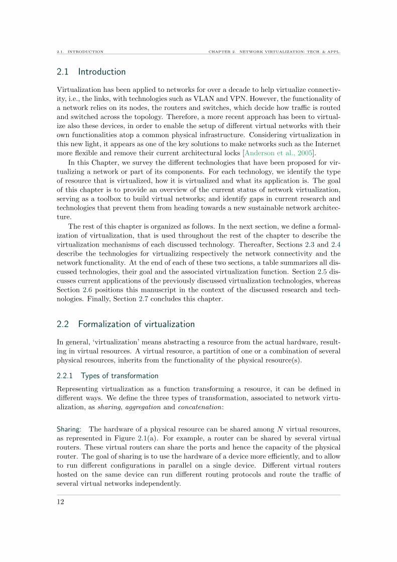
The connectivity of a network relies on links that interconnect different routing and switch-ing devices in a topology, using their ports. Connectivity also refers to the internal linksinterconnecting pairs of ports inside a single router or switch, as shown in Figure 2.3. Alink, between devices or internal, is always defined by an interconnection of two ports.Hence, virtualizing the connectivity of a network technically consists in virtualizing itsports.
14
CHAPTER 2. NETWORK VIRTUALIZATION: TECH. & APPL. 2.3. VIRTUALIZING CONNECTIVITY
Link
Internal link
device
Routing/switching
Port
Figure 2.3: Connectivity of a network: links interconnecting routing and switching devices,and links that are internal to a single device.
Virtualizing network links and ports allows one to partition the network into multiplevirtual networks with logically isolated links. Each virtual network offers individual con-nectivity, but functionalities such as routing and switching control remain globally defined.Hence different virtual networks hosted on the same physical network equipment cannotrun their own control algorithms.
This section describes the different techniques that enable to virtualize the elementsof the network, that are responsible for connectivity.
2.3.1 Virtual Local Area Networks
Virtualizing the Local Area Networks (LAN) into VLANs, standardized as 802.1Q byIEEE [IEE], is a widespread approach to separate networks into several logically isolatednetworks [VLAN, 2005]. For a given switch, only ports belonging to the same VLAN cancommunicate with one another. This has the advantage of limiting the broadcast domainof a VLAN to only links that belong to the same network, decreasing broadcast trafficand improving performance and security. In addition, a VLAN can be easily reconfiguredwhen the network topology changes. For example, a new link can be added to the VLANor moved from one VLAN to another without the necessity to intervene physically on theequipment.
Typically, a VLAN is identified based on ports (layer 1), MAC addresses (layer 2),IP addresses (layer 3) or even protocols. When a packet enters a switch, it is taggeddepending on these criteria, and henceforth its tag determines to which VLAN it belongs.A port-based VLAN consists in a set of physical ports. For a given switch, these portscannot communicate with ports that belong to other VLANs. Hence, a port-based VLANallows one to partition a switch into several virtual switches, each exploiting a dedicatedset of physical ports.
On the contrary, a layer 2 or 3 VLAN is abstracted from the physical network. Nomatter through which port a packet enters a switch, it obtains a VLAN tag based eitheron its IP or MAC address. Thus even if a host is moved from one port to another, or fromone switch to another, it will stay in the VLAN, obtain connectivity with other nodes ofthe same VLAN, and remain isolated from other VLANs. Consequently, this approach ismore flexible than port-based VLANs.
The virtualization in VLANs is implemented at the forwarding table, which is part ofthe forwarding control module of a switch as depicted in Figure 2.4. The entries of theforwarding tables contain an additional VLAN identifier that decides on the output port
15

2.3. VIRTUALIZING CONNECTIVITY CHAPTER 2. NETWORK VIRTUALIZATION: TECH. & APPL.
a packet takes. Although the functionality, e.g., the queuing and forwarding mechanism,
Hardware
VLAN VLAN VLAN
Forwarding control
Figure 2.4: Switch configured with several VLANs.
of each VLAN is the same, some exceptions allow to configure different VLANs with theirown functionality. For example, spanning tree protocol1 (STP) [STP, 2004] can be set upper VLAN on some switches.
To summarize, the switch resources that are virtualized depend on the type of VLAN(layer 1, 2, 3). Port-based VLANs divide a switch into subsets of ports, where each subsetcorresponds to one VLAN. For layer 2 or 3 VLANs, the physical ports can be sharedby several VLANs. Such a shared port is called trunk port. Hence, we formalize thevirtualization of switches’ ports for setting up VLANs as follows:
Vs : Trunk port→ Set of virtual ports
Vs, means that the trunk port is shared among a set of virtual ports.
Despite their benefits, VLANs also have some drawbacks. The fact that different IPnetworks running inside their own VLANs may share the same physical switches and linkscan lead to performance interferences between these IP networks. This prevents one frommanaging VLANs independently, when it comes to congestion or failures on a physicallink or switch [Bin Tariq et al., 2009].
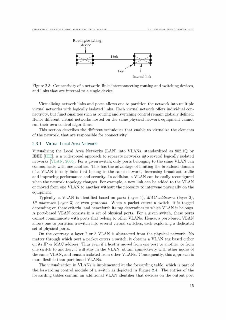
For giving a VLAN performance guarantees, many of current switches have severalqueues per port. The number of queues varies from eight up to thousands in recentequipment. On such switches, a VLAN port can be attributed a dedicated queue of thephysical port. Priorities or even rates can be configured per queue and hence per VLAN.The scheduling of the different queues allows such priorities. An example of a switch portwith several queues where each is used by a different VLAN is represented in Figure 2.5.Thus, VLANs can benefit from basic QoS such as prioritization and sometimes trafficshaping, depending on the implemented scheduling algorithms. However, the numberof VLANs with QoS is limited to the number of available queues. Moreover, relativescheduling, such as priority scheduling, leads to VLAN interdependencies in terms ofperformance. On the other hand, if VLANs are configured with absolute rates, the capacityof the links may not be fully used at some moments, or some VLANs may experiencecontention, while others do not use their full capacity.
2.3.2 Virtual Private Networks
Virtual Private Networks (VPN) enable communication over a public network such as theInternet in a secure way. In a VPN, physical paths (concatenations of possibly several
1STP prevents switching loops.
16
CHAPTER 2. NETWORK VIRTUALIZATION: TECH. & APPL. 2.3. VIRTUALIZING CONNECTIVITY
VL
AN
1
VL
AN
n
VL
AN
2
Scheduling
Port
Switch
Figure 2.5: Switch port shared by several VLANs, where each VLAN has access to aseparate queue.
links) throughout the network are presented to the VPN user as a single virtual link.Hence, we formalize the virtualization function for obtaining a VPN from a concatenationof physical links as follows:
Vc : Sequence of links→ V irtual link
A user connecting to a remote host through a VPN gets the impression that he uses asingle link. Thus, remote hosts profit from the same connectivity as if they were in thesame LAN, and can exchange data over the public network.
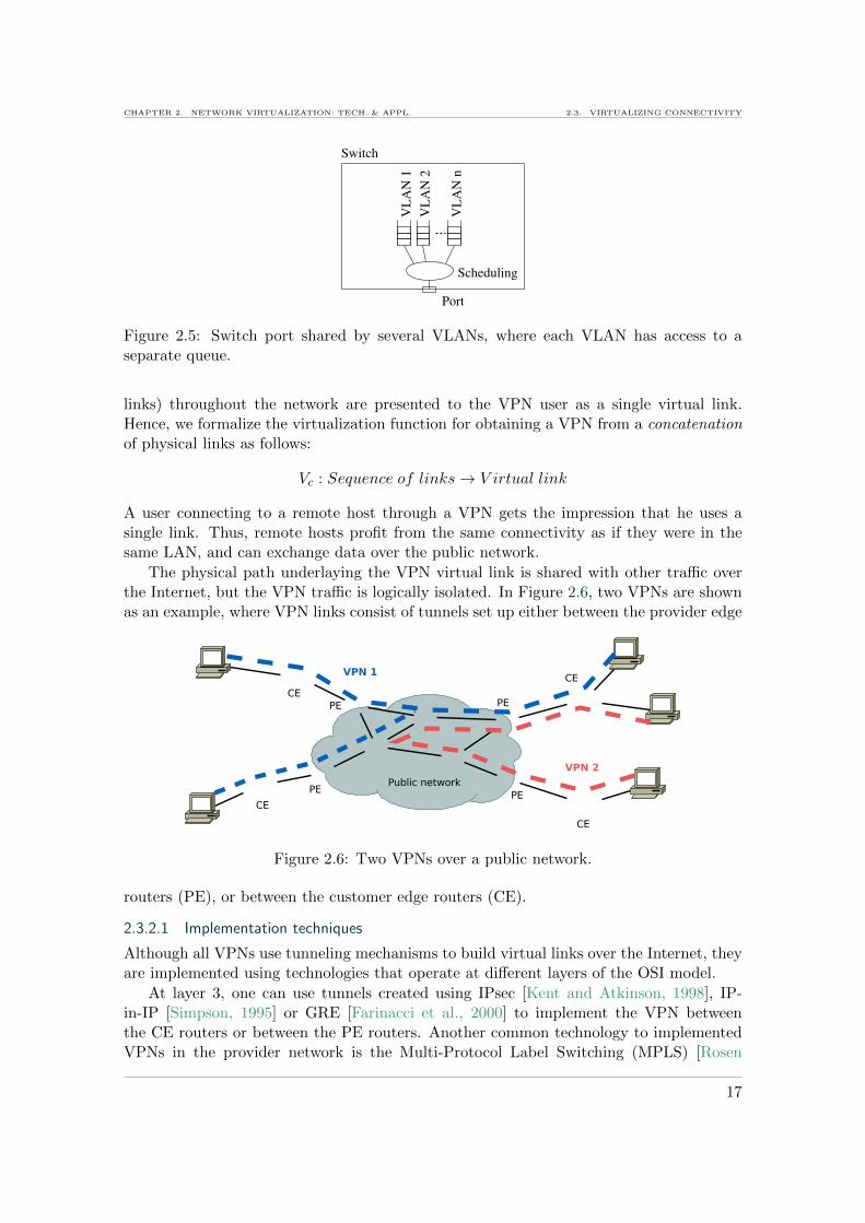
The physical path underlaying the VPN virtual link is shared with other traffic overthe Internet, but the VPN traffic is logically isolated. In Figure 2.6, two VPNs are shownas an example, where VPN links consist of tunnels set up either between the provider edge
Figure 2.6: Two VPNs over a public network.
routers (PE), or between the customer edge routers (CE).
2.3.2.1 Implementation techniques
Although all VPNs use tunneling mechanisms to build virtual links over the Internet, theyare implemented using technologies that operate at different layers of the OSI model.
At layer 3, one can use tunnels created using IPsec [Kent and Atkinson, 1998], IP-in-IP [Simpson, 1995] or GRE [Farinacci et al., 2000] to implement the VPN betweenthe CE routers or between the PE routers. Another common technology to implementedVPNs in the provider network is the Multi-Protocol Label Switching (MPLS) [Rosen
17
2.3. VIRTUALIZING CONNECTIVITY CHAPTER 2. NETWORK VIRTUALIZATION: TECH. & APPL.
et al., 2001] [Muthukrishnan and Malis, 2000], which establishes circuits termed as LabelSwitched Paths (LSP). Packets are routed inside the MPLS network along these LSPsby so called label switched routers (LSR) that take forwarding decisions based on labels.These labels are attributed to the packets at the network edge, and are changed (namelyswitched) at each LSR in the MPLS core network. A particular implementation, VPLS(Virtual Private LAN Service) [Lasserre and Kompella, 2007] allows one to set up tunnelswith point to multi-point connection.
VPNs can also be implemented directly at layer 1 [Fedyk et al., 2008]. Layer 1 VPNsare based on the Generalized Label Switching Protocol (GMPLS) [Berger, 2003], and canbe provisioned with a wavelength, or a partition of timeslots [Wu et al., 2006].
2.3.2.2 Provisioning and QoS
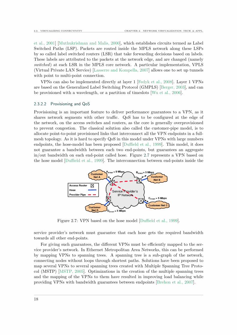
Provisioning is an important feature to deliver performance guarantees to a VPN, as itshares network segments with other traffic. QoS has to be configured at the edge ofthe network, on the access switches and routers, as the core is generally overprovisionedto prevent congestion. The classical solution also called the customer-pipe model, is toallocate point-to-point provisioned links that interconnect all the VPN endpoints in a full-mesh topology. As it is hard to specify QoS in this model under VPNs with large numbersendpoints, the hose-model has been proposed [Duffield et al., 1999]. This model, it doesnot guarantee a bandwidth between each two end-points, but guarantees an aggregatein/out bandwidth on each end-point called hose. Figure 2.7 represents a VPN based onthe hose model [Duffield et al., 1999]. The interconnection between end-points inside the
Figure 2.7: VPN based on the hose model [Duffield et al., 1999].
service provider’s network must guarantee that each hose gets the required bandwidthtowards all other end-points.
For giving such guarantees, the different VPNs must be efficiently mapped to the ser-vice provider’s network. In Ethernet Metropolitan Area Networks, this can be performedby mapping VPNs to spanning trees. A spanning tree is a sub-graph of the network,connecting nodes without loops through shortest paths. Solutions have been proposed tomap several VPNs to several spanning trees created with Multiple Spanning Tree Proto-col (MSTP) [MSTP, 2005]. Optimizations in the creation of the multiple spanning treesand the mapping of the VPNs to them have resulted in improving load balancing whileproviding VPNs with bandwidth guarantees between endpoints [Brehon et al., 2007].
18

CHAPTER 2. NETWORK VIRTUALIZATION: TECH. & APPL. 2.3. VIRTUALIZING CONNECTIVITY
2.3.3 Overlay networks
In an overlay network, the nodes are interconnected by links spanning over a path ofphysical links. The intermediate hops on the path are transparent to the overlay nodes2.The basic property of an overlay network is that it virtualizes the connectivity by makingpaths appear as links. Hence, in an overlay, a virtual link is obtained by concatenatingphysical links. We formalize this type of virtualization as follows:
Vc : Sequence of links→ V irtual link
The goal of overlay networks is to delegate some of the network functionality to the edges.This is possible as overlays can direct traffic through specific nodes called overlay nodes,e.g., fully configurable end-hosts. Users can configure the overlay nodes to perform specificoperations on the traffic (e.g., monitoring, crypting, coding, firewalling, etc.), a featurethat has been used differently to introduce new functionalities to the network. A fewexamples are given here.
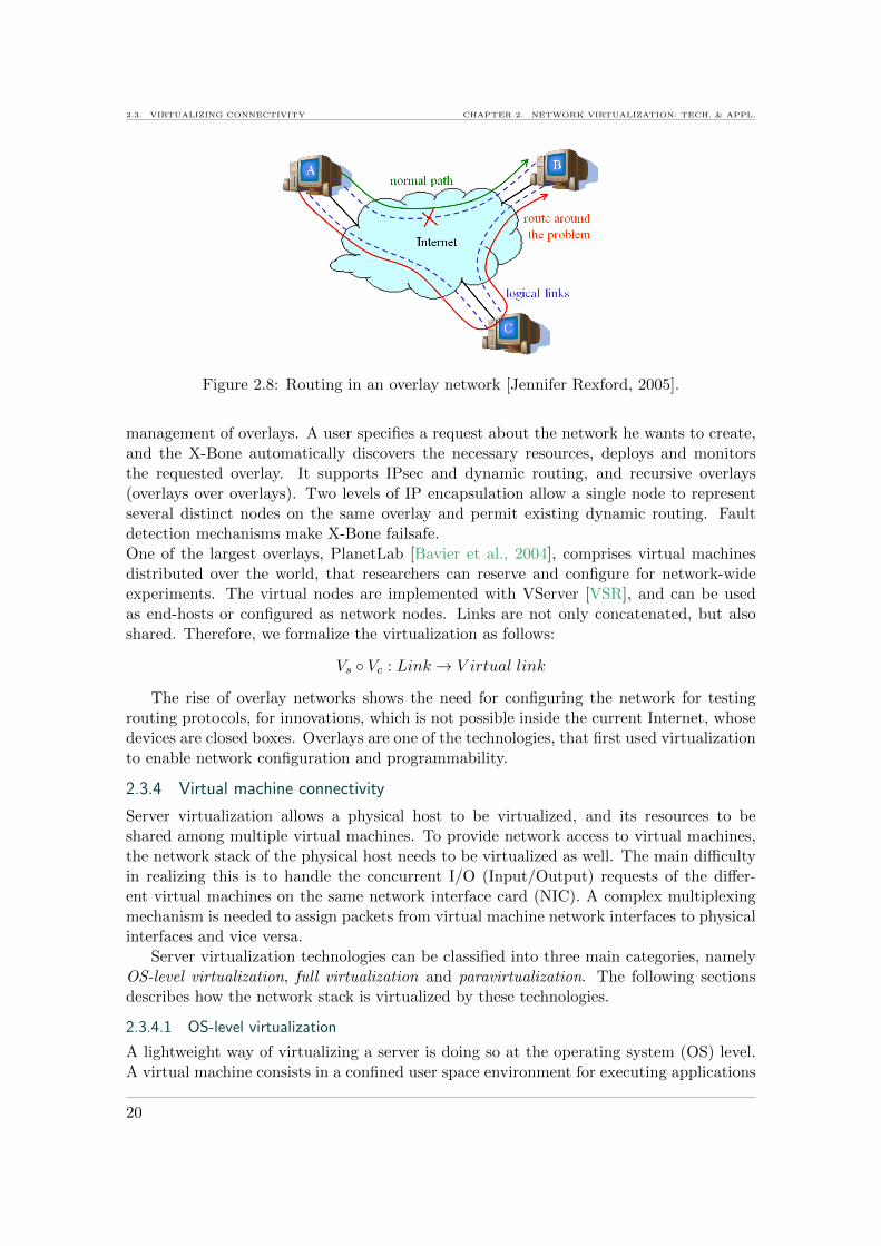
One of the first overlay strategies was Detour [Savage et al., 1999], an overlay networkcomposed of Internet end-hosts serving as routers, interconnected by tunnels. The routerscan control the network and make packets take more efficient routes, in terms of delayand packet loss rate.Also seeking to improve network QoS, OverQoS is an overlay architecture that aims atfairly sharing links between customers [Subramanian et al., 2003]. The rate of a virtuallink is determined according to loss rate and bandwidth of the physical link and a specifiedmaximum loss level. Customers get a minimum guaranteed service for the sum of theirflows, without impacting the underlying best-effort traffic.Optimizing bandwidth in overlay networks has been proposed in [Lee et al., 2008]. Band-width is monitored between the different nodes of the network, and the monitored data isused to find alternative overlay-paths through relay nodes in case of a bottleneck. Alter-native paths are chosen according to the capacity improvement compared to the originalpath.One application of overlay networks are for example content delivery services. Servers thatdeliver content over the network in a multicast way are deployed as an overlay network.Given that content should be close to clients, that network cost should be reduced, butthat the type of user requests are not know in advance, it is difficult to choose the rightserver locations when deploying a content delivery service in a big network. In [Bussonet al., 2007], the authors propose a stochastic-geometry based approach to determine ap-propriate locations for deploying servers, minimizing the deployment cost.Overlay networks are also used to deal with network failures. As an example, ResilientOverlay Networks (RON) are formed by a set of nodes located inside different routingdomains on the Internet [Andersen et al., 2001]. They communicate via a WAN-overlayto detect failures or performance degratation of the underlying paths. Packets are for-warded through RON nodes to route around failures or other detected link problems. Thererouting with RON is much faster (several seconds) than the recovery of normal routingprotocols (several minutes). Figure 2.8 illustrates this concept, where all traffic from A toB is redirected over the overlay routing node C, when the direct link from A to B fails.
Platforms for automatic deployment and management of overlays have been proposed.The X-Bone [Touch, 2000] is a distributed system allowing automatic deployment and
2A VPN is for example a particular type of overlay.
19
2.3. VIRTUALIZING CONNECTIVITY CHAPTER 2. NETWORK VIRTUALIZATION: TECH. & APPL.
Figure 2.8: Routing in an overlay network [Jennifer Rexford, 2005].
management of overlays. A user specifies a request about the network he wants to create,and the X-Bone automatically discovers the necessary resources, deploys and monitorsthe requested overlay. It supports IPsec and dynamic routing, and recursive overlays(overlays over overlays). Two levels of IP encapsulation allow a single node to representseveral distinct nodes on the same overlay and permit existing dynamic routing. Faultdetection mechanisms make X-Bone failsafe.One of the largest overlays, PlanetLab [Bavier et al., 2004], comprises virtual machinesdistributed over the world, that researchers can reserve and configure for network-wideexperiments. The virtual nodes are implemented with VServer [VSR], and can be usedas end-hosts or configured as network nodes. Links are not only concatenated, but alsoshared. Therefore, we formalize the virtualization as follows:
Vs ◦ Vc : Link → V irtual link
The rise of overlay networks shows the need for configuring the network for testingrouting protocols, for innovations, which is not possible inside the current Internet, whosedevices are closed boxes. Overlays are one of the technologies, that first used virtualizationto enable network configuration and programmability.
2.3.4 Virtual machine connectivity
Server virtualization allows a physical host to be virtualized, and its resources to beshared among multiple virtual machines. To provide network access to virtual machines,the network stack of the physical host needs to be virtualized as well. The main difficultyin realizing this is to handle the concurrent I/O (Input/Output) requests of the differ-ent virtual machines on the same network interface card (NIC). A complex multiplexingmechanism is needed to assign packets from virtual machine network interfaces to physicalinterfaces and vice versa.
Server virtualization technologies can be classified into three main categories, namelyOS-level virtualization, full virtualization and paravirtualization. The following sectionsdescribes how the network stack is virtualized by these technologies.
2.3.4.1 OS-level virtualization
A lightweight way of virtualizing a server is doing so at the operating system (OS) level.A virtual machine consists in a confined user space environment for executing applications
20
CHAPTER 2. NETWORK VIRTUALIZATION: TECH. & APPL. 2.3. VIRTUALIZING CONNECTIVITY
on top of the host kernel. The advantage is that virtual machines access hardware justlike applications do. On the other hand, as a virtual machine runs the OS of the host andgenerally does not have its own kernel, isolation between virtual machines is limited.
The main OS-level virtualization technologies include OpenVZ [OVZ],Linux VServer [VSR], Virtuozzo [VRZ], FreeBSD Jails [JAI] and User-Mode-Linux(UML) [UML]. VServer and FreeBSD Jails are also referred to as container-based vir-tualization technologies. In this terminology, a virtual machine is a container that hostsan OS userspace and shares the host kernel with other virtual machines. Virtual ma-chines access the network through sockets bound to dedicated IP addresses [Soltesz et al.,2007] [Kamp and Watson, 2000]. In both VServer and FreeBSD Jails the virtual machineuser cannot configure the routing table or change the IP addresses of the virtual machinenetwork interfaces on the fly. Hence, different virtual machines share the network stack inthe same way that applications share the network stack on a classical Linux OS. That is,different virtual machines access the same NIC through different TCP/UDP sockets, andthe network stack is virtualized as:
Vs : TCP/IP stack → Set of sockets
Each virtual machine hosted on a VServer can get specific network bandwidth. Thetraffic of the different virtual machines sharing a physical NIC is shaped using the classicalHierarchy Token Bucket (HTB) of the Linux Traffic Control tools [TC]. The main advan-tage of OS-level virtualization in terms of network performance is that, without incurringany CPU overhead, virtual machines can achieve the same network throughput than ona classical (non virtualized) Linux system, which is not the case with other virtualizationtechnologies.
Another OS-level virtualization technology, OpenVZ [OVZ], works basically the sameway as VServer, but an alternative option on the network configuration allows virtualmachine users to set up their own IP addresses on specific virtual Ethernet interfaces.These interfaces are bridged to the physical interface. Here, virtualization takes place atthe Ethernet NIC driver level, so that the virtualization function applied to the driverexposes a virtual Ethernet NIC to each virtual machine:
Vs : Ethernet driver→ Set of virtual ethernet drivers
While virtualizing the Ethernet driver, gives more flexibility to virtual machines—they canhave configurable virtual NICs—its drawback is network performance. Network through-put on such virtual interfaces is less than with the default configuration, using differentsockets.
Another OS-level virtualization technique, different from those described above, isUser-Mode Linux (UML) [Dike, 2001] [UML]. It enables virtualization by running Linuxkernels in userspace. The NIC is virtualized by exposing TUN [TUN] interfaces to virtualmachines. UML can fully virtualize the kernel network stack, exposing a virtual networkstack to each virtual machine. Hence, the virtualization function in UML is:
Vs : Kernel network stack→ Set of virtual network stacks
The additional processing causes a huge impact on performance. UML virtual machinesachieve less than half of the throughput of a classical Linux server [Koh et al., 2006].In such systems, rate can also be controlled using software queuing and traffic controlmechanisms.
21
2.3. VIRTUALIZING CONNECTIVITY CHAPTER 2. NETWORK VIRTUALIZATION: TECH. & APPL.
2.3.4.2 Full virtualization
Full virtualization is based on a hypervisor that manages virtual machines and their accessto the hardware of a host. Common full virtualization technologies include KVM [Kivityet al., 2007], VMware [VMW], VirtualBox [VBX], Hyper-V [HYV], and Xen (with ahardware virtual machine option) [Pratt et al., 2005]. Contrary to OS-level virtualization,full virtualization presents completely emulated NICs to virtual machines.Emulation is a technology, that can abstract a device from its hardware, presenting it asan emulated device to a virtual machine which perceives it as a physical device. Whena machine accesses an emulated NIC, all instructions are translated to actual hardwareinstructions, and executed on the NIC, as represented on the left part of Figure 2.9. Hence,emulated NICs expose the same functionality than physical NICs, and virtual machines canuse native NIC drivers to access these emulated NICs. A common emulation technologyused for this purpose is Qemu [QEM]. In summary, emulation virtualizes the whole kernelnetwork stack in order to expose several full-featured NICs to virtual machines. Hence,several virtual machines have each their own virtual network stacks, that result fromsharing the Kernel network stack:
Vs : Kernel network stack→ Set of virtual network stacks
These full virtualized systems use hardware virtualization support of the CPU, runningunmodified OSes inside virtual machines and providing improved virtual machine isola-tion. However, it does not improve the network performance as NICs are emulated andemulation is very costly in terms of processing. Taking the example of Kernel BasedVirtual Machines (KVM), the NIC is emulated using Qemu and exposed to the virtualmachines. As this requires the translation of all instructions between the emulated NICand the hardware NIC, very high CPU overhead is expected, which can rapidly becomea bottleneck to virtual network performance, besides overall virtual machine performanceduring high network loads. This virtual machine performance is quantified in Chapter 3.Therefore, many full virtualization solutions come now with special network drivers, andperform paravirtualization.
2.3.4.3 Paravirtualization
It requires to modify the virtual machine OS to integrate special drivers to access thehardware, especially disks and NICs, as represented on the right part of Figure 2.9 Par-avirtualization is similar to full virtualization with some changes. One of the first par-avirtualization technologies was Denali [Whitaker et al., 2002], using a Virtual MachineMonitor (VMM) or hypervisor that virtualizes the hardware and exposes them to the vir-tual machines. The most commonly used paravirtualization solution today is Xen [Barhamet al., 2003]. Note that Xen also offers the option to be used in full virtualization mode,running so called Hardware Virtual Machines (HVM) [Pratt et al., 2005]. Yet, by default,it performs paravirtualization. But also KVM [Kivity et al., 2007] allows paravirtualizationwith the specialized virtio driver [Russell, 2008], that virtualizes the access to network andstorage devices. Other technologies, like VMware and VirtualBox also propose to patchthe virtual machine OSes to update the I/O drivers in virtual machines, and achieve bet-ter I/O performance. In a paravirtualized system, the physical NIC is exposed throughspecial virtual NIC drivers to the virtual machine. Hence, the virtualization function isapplied to the NIC driver and several virtual NICs are exposed to the virtual machines:
22
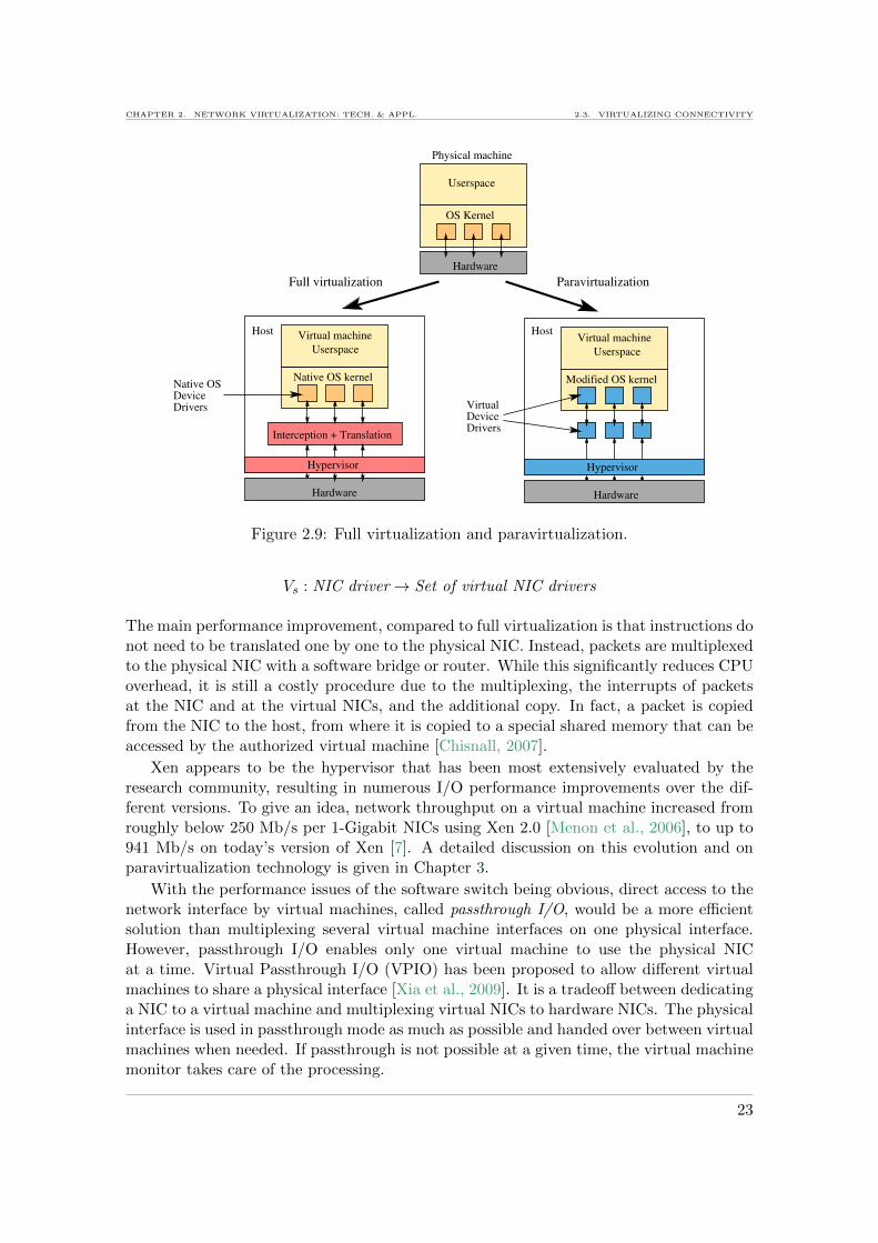
CHAPTER 2. NETWORK VIRTUALIZATION: TECH. & APPL. 2.3. VIRTUALIZING CONNECTIVITY
DeviceVirtual
Drivers
Native OSDeviceDrivers
Hardware
Hardware Hardware
Virtual machine Virtual machine
Native OS kernel Modified OS kernel
HostHost
Interception + Translation
Hypervisor Hypervisor
OS Kernel
Userspace
Userspace Userspace
Physical machine
ParavirtualizationFull virtualization
Figure 2.9: Full virtualization and paravirtualization.
Vs : NIC driver→ Set of virtual NIC drivers
The main performance improvement, compared to full virtualization is that instructions donot need to be translated one by one to the physical NIC. Instead, packets are multiplexedto the physical NIC with a software bridge or router. While this significantly reduces CPUoverhead, it is still a costly procedure due to the multiplexing, the interrupts of packetsat the NIC and at the virtual NICs, and the additional copy. In fact, a packet is copiedfrom the NIC to the host, from where it is copied to a special shared memory that can beaccessed by the authorized virtual machine [Chisnall, 2007].
Xen appears to be the hypervisor that has been most extensively evaluated by theresearch community, resulting in numerous I/O performance improvements over the dif-ferent versions. To give an idea, network throughput on a virtual machine increased fromroughly below 250 Mb/s per 1-Gigabit NICs using Xen 2.0 [Menon et al., 2006], to up to941 Mb/s on today’s version of Xen [7]. A detailed discussion on this evolution and onparavirtualization technology is given in Chapter 3.
With the performance issues of the software switch being obvious, direct access to thenetwork interface by virtual machines, called passthrough I/O, would be a more efficientsolution than multiplexing several virtual machine interfaces on one physical interface.However, passthrough I/O enables only one virtual machine to use the physical NICat a time. Virtual Passthrough I/O (VPIO) has been proposed to allow different virtualmachines to share a physical interface [Xia et al., 2009]. It is a tradeoff between dedicatinga NIC to a virtual machine and multiplexing virtual NICs to hardware NICs. The physicalinterface is used in passthrough mode as much as possible and handed over between virtualmachines when needed. If passthrough is not possible at a given time, the virtual machinemonitor takes care of the processing.
23

2.3. VIRTUALIZING CONNECTIVITY CHAPTER 2. NETWORK VIRTUALIZATION: TECH. & APPL.
Another solution to improve the network performance of virtual machines is to ‘re-place’ the software switch that interconnects virtual machines on a host with a hardwareswitch. This means that all virtual machine traffic is by default sent out of the hosttowards a classical hardware switch. This switch then forwards the traffic towards thedestination host, which can be a virtual machine located on the same host of the source ofthe traffic [Congdon et al., 2010]. The advantage is that not only forwarding, but variouscostly operations, such as address learning, access control, or other can be handled by thehardware switch.
Another recent software network virtualization solution is Crossbow [Tripathi et al.,2009], proposed initially for OpenSolaris. Crossbow allows one to build virtual NICs usingso-called virtualization lanes, which are network stacks with dedicate receive and transmitbuffers (called rings). Packets are directly classified on layer 2 into the right virtualizationlane. These virtualization lanes can be implemented in software, but this does not enableany performance isolation or fairness in the resource sharing. Therefore, NICs with virtu-alized hardware are required, where each virtualization lane has its own receive ring, andhence does not impact the packet rate of other lanes.
Reviewing these different software virtualization techniques, we note that passthroughis the most efficient solution as it causes no performance overhead. This brings us to theconclusion that specialized NICs are needed, which can be directly accessed by severalvirtual machines in parallel.
2.3.5 Virtualized NICs
When talking about hardware-assisted virtualization, such as KVM [Kivity et al., 2007],it generally means that the CPU is virtualized, to give several parallel virtual machinesindependent and secure access to it. While this is meant to improve computing perfor-mance it does not necessary improve the network performance, as network I/O does notbenefit from CPU virtualization. Therefore, NICs with hardware virtualization supporthave been developed.
Arsenic is such a type of NIC, with an extended interface to the OS and to appli-cations [Pratt and Fraser, 2001]. It exposes virtual interfaces to the applications, whereeach has its own transmit and receive queue. This discharges the OS, as the multiplexingbetween virtual interfaces and the real physical interface is implemented directly in theArsenic NIC. In addition, traffic shaping and scheduling enable the control of applicationtraffic on the transmission queue.
More recently, Intel has implemented solutions to dedicate transmit and receive queuesto virtual machines on 1 to 10 Gb/s Ethernet NICs. VMDq (Virtual Machine Devicequeues) is one such technology dedicating one queue to a virtual machine, handled bya dedicated CPU core [VMDq, 2008]. An incoming packet triggers an interrupt and isdirectly sent to the right queue and handled by the CPU core dedicated do the queue.This replaces the costly multiplexing mechanisms, that would otherwise take place in thehypervisor. Instead, the workload is spread among multiple cores. In summary, withVMDq, the NIC is shared into virtual NICs, where each has a dedicated queue. Thevirtualization function of VMDq can hence be formalized as:
Vs : NIC→ Set of virtual NICs
24
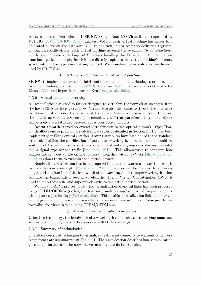
CHAPTER 2. NETWORK VIRTUALIZATION: TECH. & APPL. 2.3. VIRTUALIZING CONNECTIVITY
An even more efficient solution is SR-IOV (Single-Root I/O Virtualization) specified byPCI SIG [IOVb] [SR-IOV, 2009]. Likewise VMDq, each virtual machine has access to adedicated queue on the hardware NIC. In addition, it has access to dedicated registers.Through a specific driver, each virtual machine accesses the so called Virtual Functions,which communicate with Physical Functions handling the Ethernet port. Using thesefunctions, packets on a physical NIC are directly copied to the virtual machine’s memoryspace, without the hypervisor getting involved. We formalize the virtualization mechanismused by SR-IOV as:
Vs : NIC driver function→ Set of virtual functions
SR-IOV is implemented on some Intel controllers, and similar technologies are providedby other vendors, e.g., Myricom [MYR], Neterion [NET]. Software support exists forLinux [IOVa] and hypervisors, such as Xen [Dong et al., 2008].
2.3.6 Virtual optical connectivity
All technologies discussed so far are designed to virtualize the network at its edges, fromthe host’s NICs to the edge switches. Virtualizing also the connectivity over the Internet’sbackbone must consider the sharing of the optical links and cross-connects. However,the optical network is governed by a completely different paradigm. In general, directconnections are established between edges over optical circuits.
Recent research started to extend virtualization to the optical network. OpenFlow,which allows one to program a switch’s flow tables as detailed in Section 2.4.1.2, has beenimplemented in Ciena optical switches. Layer 1 attributes have been added to the standardprotocol, enabling the specification of particular wavelength, on which traffic should besent out of the switch, or to select a virtual concatenation group or a starting time-slotand a signal type for the traffic [Das et al., 2010]. This allows users to configure howpackets are sent out to the optical network. Together with FlowVisor [Sherwood et al.,2009], it allows them to virtualize the optical network.
Bandwidth virtualization has been proposed in optical networks as a way to decouplebandwidth from wavelength [Melle et al., 2008]. Services can be mapped to subwave-lengths, with a fraction of the bandwidth of the wavelength, or to superwavelengths, thatcombine the bandwidth of several wavelengths. Digital Virtual Concatenation (DVC) isused to map these sub- and superwavelengths to the actual optical network.
Within the GENI project [GEN], the virtualization of optical links has been proposedusing OFDM/OFDMA (orthogonal frequency multiplexing/orthogonal frequency multi-plexing access) technology [Wei et al., 2009]. This enables virtualization links at subwave-length granularity, by assigning so-called subcarriers to virtual links. Consequently, weformalize the virtualization using OFDM/OFDMA as:
Vs : Wavelength→ Set of optical subcarriers
Using this technology, the bandwidth of a wavelength can be shared by carrying numeroussubcarriers on it—e.g., 256 subcarriers on a 10 Gb/s wavelength.
2.3.7 Summary of technologies
The above described techniques to virtualize the different connectivity elements of networkcomponents are summarized in Table 2.1. The next Section describes how virtualizationgoes a step further into the network, virtualizing also its functionality.
25
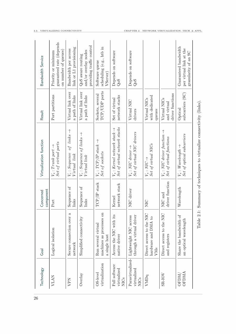
2.3. VIRTUALIZING CONNECTIVITY CHAPTER 2. NETWORK VIRTUALIZATION: TECH. & APPL.
Tec
hn
olog
yG
oal
Con
cern
edco
mp
onen
tV
irtu
aliz
atio
nfu
nct
ion
Res
ult
Ban
dw
idth
Ser
vice
VL
AN
Log
ical
isol
atio
nP
ort
Vs
:Trunkport→
Setof
virtualports
Port
part
itio
ns
Pri
ori
tyor
min
imu
mgu
ara
nte
edra
te(d
epen
ds
onnu
mb
erof
qu
eues
)
VP
NS
ecu
reco
nn
ecti
onov
era
net
wor
kS
equ
ence
of
lin
ks
Vc
:Sequence
oflinks→
Virtuallink
Vir
tual
lin
kov
era
path
of
lin
ks
Ban
dw
idth
per
acc
ess
lin
kor
L1
pro
vis
ion
ing
Ove
rlay
Sim
pli
fied
con
nec
tivit
yS
equ
ence
of
lin
ks
Vc
:Sequenceof
links→
Virtuallink
Vir
tual
lin
kov
era
path
of
lin
ks
QoS
aware
rou
tin
gan
d/or
over
lay
nod
esp
rovid
ing
traffi
cco
ntr
ol
OS
-lev
elvir
tual
izat
ion
Ru
nse
ver
alvir
tual
mac
hin
esas
pro
cess
eson
asi
ngl
eh
ost
TC
P/IP
stack
Vs
:T
CP
/IP
stack→
Setof
sockets
Sock
ets,
seve
ral
TC
P/U
DP
port
sS
oft
ware
qu
eue
sch
edu
lin
g(e
.g.,
htb
inV
Ser
ver)
Fu
llso
ftw
are
vir
tual
ized
NIC
s
Acc
ess
the
NIC
wit
hit
sn
ativ
edri
ver
Ker
nel
net
work
stack
Vs
:K
ern
eln
etw
ork
stack→
Set
of
virt
ual
net
work
stack
sS
etof
vir
tual
net
work
stack
sD
epen
ds
on
soft
ware
QoS
Par
avir
tual
ized
-vir
tual
ized
NIC
s
Lig
htw
eigh
tN
ICac
cess
thro
ugh
avir
tual
dri
ver
NIC
dri
ver
Vs
:N
ICdri
ver→
Set
of
virt
ual
NIC
dri
vers
Vir
tual
NIC
dri
vers
Dep
end
son
soft
ware
QoS
VM
Dq
Dir
ect
acce
ssto
the
NIC
har
dw
are
and
DM
Ato
VM
s
NIC
Vs
:N
IC→
Set
of
virt
ual
NIC
sV
irtu
al
NIC
sw
ith
ded
icate
dqu
eues
SR
-IO
VD
irec
tac
cess
toth
eN
ICan
dre
gist
ers
NIC
an
dd
rive
rfu
nct
ion
Vs
:N
ICdri
ver
fun
ctio
n→
Set
of
virt
ual
fun
ctio
ns
Vir
tual
NIC
san
dvir
tual
dri
ver
fun
ctio
ns
OF
DM
/O
FD
MA
Sh
are
the
ban
dw
idth
ofan
opti
cal
wav
elen
gth
Wav
elen
gth
Vs
:W
ave
len
gth→
Set
of
opti
cal
subc
arr
iers
Op
tica
lsu
bca
rrie
rs(S
C)
Gu
ara
nte
edban
dw
idth
per
vir
tual
lin
kat
the
granu
lari
tyof
an
SC
Tab
le2.
1:S
um
mar
yof
tech
niq
ues
tovir
tual
ize
con
nec
tivit
y(l
inks)
.
26

CHAPTER 2. NETWORK VIRTUALIZATION: TECH. & APPL. 2.4. VIRTUALIZING FUNCTIONALITY
2.4 Virtualizing Functionality
Virtualizing the connectivity is a traditional way to share a network among different usersor applications. It allows networks to better exploit resources, e.g., the available bandwidthon the links, and to logically isolate the traffic of different users by grouping them intovirtual networks. However, virtualizing only the connectivity does not provide each virtualnetwork with individual functionality, such as routing and forwarding mechanisms. Hence,it is necessary to virtualize functionality so that each virtual network user or operator canset up its own protocol stack, or even specify packet queuing and scheduling differentfrom other virtual networks. In this way, a virtual network could be configured to providespecific QoS levels.
A virtual network should not only be usable, but also configurable or ideally, pro-grammable.
Traditionally, an operator configures an equipment, its functionality (e.g., routing,VLANs) and QoS. The users only connect to the network and transfer data. Virtualizingnetwork functionality creates a new role,a virtual network operator (VNO), in chargeof configuring the virtual equipment [Feamster et al., 2007]. The physical equipment isstill maintained and configured by a physical network provider or operator. Figure 2.10illustrates the layers in this new concept.
Users Users Users
Hardware
VNO VNO VNO
Physical network provider
Figure 2.10: Virtualization of network functionality; a new role—the Virtual NetworkOperator (VNO)—can configure his virtual network.
The novelty of such an approach is that the network devices are no longer black boxes.VNOs can configure their virtual network partitions in parallel by accessing the virtualrouters and switches. This can move the programmability of overlay networks from end-hosts to network devices, avoiding to deviate traffic through overlay hosts, which areend-hosts.
Network functionality can be configured at the network or routing layer, and at theforwarding layer. The following section starts by introducing the concept of programmingrouters, and then surveys the different technologies to virtualize the functionality of thenetwork and to configure virtual network devices.
2.4.1 Network programmability
This section introduces the concept of programmability and its has two (actually comple-mentary) important roles:
• It is a main motivation for network virtualization: with virtualization, different vir-tual networks can run on top of a physical infrastructure, and each virtual network
27

2.4. VIRTUALIZING FUNCTIONALITY CHAPTER 2. NETWORK VIRTUALIZATION: TECH. & APPL.
can be programmed differently. That is, each virtual network can run its own pro-tocol, forwarding mechanism, etc.
• It is an enabler of network virtualization: Some components of the network can beprogrammed so as to run several virtual networks in parallel, in different partitionsof the physical network.
In this section, we briefly survey approaches to program the network, and that canenable virtualization in the network.
2.4.1.1 Programmable devices
Click router is a widely used router programming platform, consisting of a modular soft-ware router running on Linux or FreeBSD platforms [Morris et al., 1999]. A user canbuild its own router by chaining a set of click elements that perform the classical tasksexecuted on a packet on its path throughout a router. Such elements implement for exam-ple queues, dequeuing processes, filtering modules, modules to retrieve packets from NICs,among others [CLI]. Users can also program custom elements and insert them on the datapath, building their own fully programmable and configurable router. This tool enablesexperimentation and proof of concept, and may even be used in production networks ontoday’s high-performance servers. It has for example been used at different levels to buildvirtual routers, as later described in Section 2.4.4
Considering the hardware, even though boxes are mostly closed, research effort hasbeen made to expose part of their features for configuration, and for programmability.Orphal is an example of an open router platform with an API for programming custommodules on hardware routers [Mogul et al., 2008]. These modules, also called switchlets,have their own address spaces and control threads, and can operate on packets or flowsor implement control plane functions. For example, switchlets can perform monitoringand implement firewalls, NAT, or even OpenFlow; a protocol discussed in the next sec-tion. Using Orphal, a user can program even packet processing on a hardware vendorplatform. This becomes really interesting in a virtualized context, where users can ma-nipulate confined environments. Similarly, JunOS SDK enables the creation of customservice modules in JunOS [Kelly et al., 2010]. Plug-ins that perform for example packetmanipulation, monitoring, traffic classification, are added to these service modules. Othervendors propose APIs and SDKs for hosting third-party applications in hardware routers,e.g., Cisco’s Application eXtension Platform [CSD, 2008]. Jointly with virtualization,these features become interesting as different users could program their own modules torun in parallel.
Programming the lookup of hardware in in high-speed routers has been proposed witha flexible modular lookup module called PLUG [De Carli et al., 2009]. It enables pro-gramming a customized pipeline of lookup tiles where each tile can be adapted to thetype of lookup performed. In this efficient design, performance is close to that achievedwith specialized lookup modules. Such programmable lookup modules could be used tovirtualize the lookup mechanism in routers and switches.
2.4.1.2 Moving the control plane out of the box
One step towards enabling the programmability of the network as a logical entity is todecouple the control plane from the data plane, taking the control plane out of the routers,
28
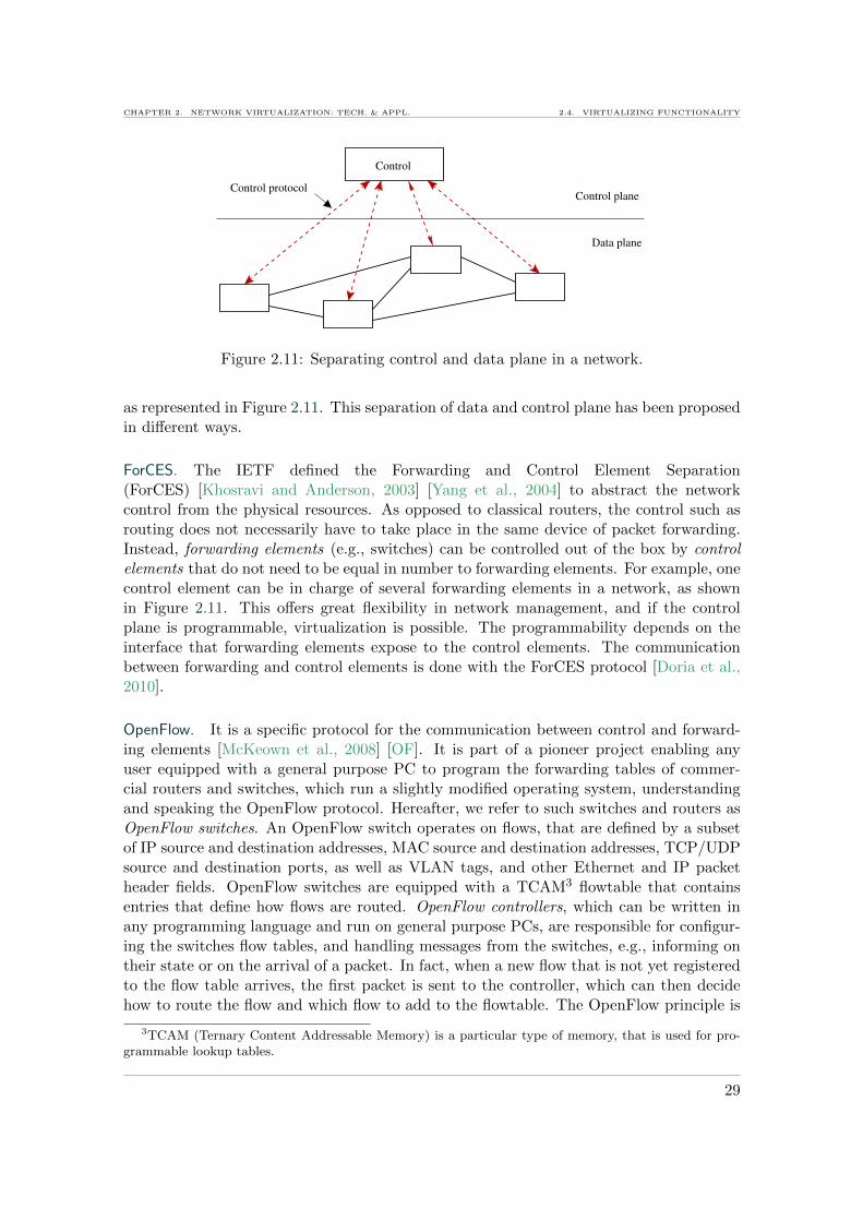
CHAPTER 2. NETWORK VIRTUALIZATION: TECH. & APPL. 2.4. VIRTUALIZING FUNCTIONALITY
Control
Control plane
Data plane
Control protocol
Figure 2.11: Separating control and data plane in a network.
as represented in Figure 2.11. This separation of data and control plane has been proposedin different ways.
ForCES. The IETF defined the Forwarding and Control Element Separation(ForCES) [Khosravi and Anderson, 2003] [Yang et al., 2004] to abstract the networkcontrol from the physical resources. As opposed to classical routers, the control such asrouting does not necessarily have to take place in the same device of packet forwarding.Instead, forwarding elements (e.g., switches) can be controlled out of the box by controlelements that do not need to be equal in number to forwarding elements. For example, onecontrol element can be in charge of several forwarding elements in a network, as shownin Figure 2.11. This offers great flexibility in network management, and if the controlplane is programmable, virtualization is possible. The programmability depends on theinterface that forwarding elements expose to the control elements. The communicationbetween forwarding and control elements is done with the ForCES protocol [Doria et al.,2010].
OpenFlow. It is a specific protocol for the communication between control and forward-ing elements [McKeown et al., 2008] [OF]. It is part of a pioneer project enabling anyuser equipped with a general purpose PC to program the forwarding tables of commer-cial routers and switches, which run a slightly modified operating system, understandingand speaking the OpenFlow protocol. Hereafter, we refer to such switches and routers asOpenFlow switches. An OpenFlow switch operates on flows, that are defined by a subsetof IP source and destination addresses, MAC source and destination addresses, TCP/UDPsource and destination ports, as well as VLAN tags, and other Ethernet and IP packetheader fields. OpenFlow switches are equipped with a TCAM3 flowtable that containsentries that define how flows are routed. OpenFlow controllers, which can be written inany programming language and run on general purpose PCs, are responsible for configur-ing the switches flow tables, and handling messages from the switches, e.g., informing ontheir state or on the arrival of a packet. In fact, when a new flow that is not yet registeredto the flow table arrives, the first packet is sent to the controller, which can then decidehow to route the flow and which flow to add to the flowtable. The OpenFlow principle is
3TCAM (Ternary Content Addressable Memory) is a particular type of memory, that is used for pro-grammable lookup tables.
29

2.4. VIRTUALIZING FUNCTIONALITY CHAPTER 2. NETWORK VIRTUALIZATION: TECH. & APPL.
described in detail in Chapter 5, where we use the programmability of the flowtable to setup virtual networks.
The following sections describe the different propositions for introducing programma-bility to the network when virtualizing it.
2.4.2 Hardware router virtualization
Virtualization has been proposed for hardware routers, mainly for consolidation purposes,i.e., running several virtual routers inside a single physical device to reduce equipment costand space. Moreover, the routing hardware has been virtualized to run different virtualrouters with their own routing protocols on the same device. Some examples of how routermanufacturers propose virtualization are discussed next.
2.4.2.1 Virtual Routing and Forwarding
Virtual Routing and Forwarding (VRF) partitions a single physical router, where eachpartition or logical router can run a different routing instance. This is achived by runningseveral parallel routing tables, one per VRF. We formalize the virtualization of a routingtable as follows:
Vs : Routing table→ Set of virtual routing table instances
With this, several routers can run in parallel on the same equipment. Hence, at a giventime, several virtual networks can share the devices using VRF. Some types of VPN exploitthis technology to route traffic differently in each VPN, e.g., based on MPLS [Rosen andRekhter, 1999].
2.4.2.2 Virtual Router Redundancy Protocol
The inverse approach to sharing consists in aggregating several physical routers into avirtual router. Virtual Router Redundancy Protocol (VRRP) [Hinden, 2004] manages aset of aggregated physical routers that belong to the same LAN. It ensures that, if onerouter fails, another takes over the control. Only one of the physical routers, the ‘master’,is actually running and routing the network traffic, the other are backup routers. In casethe master fails, VRRP ensures that the routing task is delegated to one of the backuprouters, keeping the network running. The set of redundant physical routers, managedby VRRP, is seen by the network like a single logical or virtual router. We can henceformalize the virtualization (aggregation of routers) performed by VRRP as follows:
Va : Set of routers→ Virtual router
2.4.2.3 Router consolidation
Consolidation is a term frequently used in the context of server virtualization. Servers areoften underutilized, and with virtualization one can consolidate several virtual servers intoa single physical server, resulting in better resource usage as well as savings in equipmentcost and floor space.
Trying to reap similar benefits, consolidation is proposed by manufacturers of networkequipment. With improvements in hardware (10 Gb/s links, high switching power), itis appealing to consolidate routers and switches into a single equipment—a virtualizedrouter.
30

CHAPTER 2. NETWORK VIRTUALIZATION: TECH. & APPL. 2.4. VIRTUALIZING FUNCTIONALITY
Major vendors propose virtualized network routers that aggregate a whole network ofrouters and switches inside a single device, reducing the complexity of the cabled network,and saving cost and space. Figure 2.12 illustrates this concept, as realized by Cisco4 inInternet access routers, also called Points of Presence (PoPs) [HVR, 2008]. In this exam-
Figure 2.12: Consolidation of network resources in a PoP [HVR, 2008].
ple, a network of routers and switches (A, B, C and D on the left part of Figure 2.12) areconsolidated as virtual entities into a single device (right part of Figure 2.12). Such a largenetwork device, hosting the different virtual routers and switches, implements virtualiza-tion in different ways depending on the performance requirements. One implementationconsists in dedicating a hardware control engine and a hardware forwarding engine to avirtual routers [JCS, 2009] [HVR, 2008]. The control engine can be configured with thesuitable routing protocol. This is not really virtualization, but rather the segmentationof a hardware platform into several routing and switching modules. Yet, as it shares ahardware platform, we formalize this transformation with the sharing function as follows:
Vs : Router platform→ Set of dedicated routing and forwarding hardware
With this approach, virtual routers benefit from high performance and isolation as theyhave dedicated hardware resources. As a drawback, the number of virtual routers islimited to the number of hardware routing and forwarding engines present on the platform.The Juniper JCS1200 technology features for example 12 routing engines [JCS, 2009].Moreover, it does not offer a high degree of flexibility in the granularity of resourcesallocated to a virtual router. A router can for example only allocate entire ports, even ifit requires less capacity than what the port offers.
Another type of implementation manufacturers propose consists in virtualizing onlythe software part of the equipment. This means that a virtual router does not havededicated hardware, but shares the hardware with other virtual routers. As an example,on a Juniper router, up to 16 logical routers can be implemented on top of a single physicalrouting engine [Kolon, 2004]. Similarly, Cisco can virtualize routers in the software partof their equipment [HVR, 2008]. Hence, with this approach, a single routing engine isvirtualized to run several virtual routing instances, as formalized below:
4Note that other equipment manufacturers adopted similar implementations.
31

2.4. VIRTUALIZING FUNCTIONALITY CHAPTER 2. NETWORK VIRTUALIZATION: TECH. & APPL.
Vs : Routing engine→ Set of virtual routing instances
For isolating virtual routers in terms of performance, a class of service per logical routercan be configured to control their rate. However, the control is performed in software anddoes not offer the same degree of isolation as dedicated hardware virtual router.
2.4.3 Distributed virtual switches
A distributed virtual switch abstracts a network of switches, hiding its complexity andallowing it to be managed in a simple way, as a single switch. This concept is mainlyused in the context of server virtualization, as shown in Figure 2.13. The left side shows
VMs
Host
Switches VirtualizationDistributed
Virtual
Switch
Figure 2.13: Distributed virtual switch.
a network interconnecting four hosts, each running a set of virtual machines (VMs). Inthis interconnection of virtual machines, there are two levels of switching. First, a switchinside each host multiplexes and forwards the traffic of the virtual machines and the NIC.Second, a network of switches interconnects the hosts. With distributed virtual switches,the complexity of this network is hidden, as represented on the right side of Figure 2.13.
With this type of virtualization, a network of switches is concatenated, i.e., aggregatedbut with respect to a specific topology, in order to hide complexity. Hence, we formalizethe virtualization as follows:
Vc : Network of switches→ Virtual switch
Cloud solutions propose distributed switches within their management platforms, whichfacilitate the management of a cluster of virtual machines that are distributed over differ-ent physical machines.For example, VMware vSphere 4 platform [VSP] has introduced vDS [vDS, 2009] (virtualNetwork Distributed Switch). vDS enables the centralized management of the switchingbetween virtual machines hosted on different hardware servers, like a single switch. For ex-ample, private VLANs can be set up to interconnect only a subset of the virtual machinesconnected to the vDS. Moreover, virtual machines can be migrated transparently fromone host to another, without loosing connectivity as they remain on the ‘same’ switch, thevDS. An interesting feature for controlling the traffic of virtual machines is traffic shaping,which can be set up on the virtual ports of vDS. Moreover, virtual machine traffic can beclassified into different types, such as virtual machine migration traffic and managementtraffic, each of which is provisioned with different rates. A specific implementation of vDSfor VMware, that supports up to 64 hosts, is the Cisco Nexus 1000V [NEX, 2010].
Another such technology is Brocade’s Virtual Cluster Switching (VCS) [VCS, 2010].Likewise vDS, it manages a topology of networked switches, including hardware switchesand software switches (those interconnecting virtual machine inside a single host). Thistopology is viewed and managed as a single logical switch, just like the virtual distributed
32

CHAPTER 2. NETWORK VIRTUALIZATION: TECH. & APPL. 2.4. VIRTUALIZING FUNCTIONALITY
switch represented in Figure 2.13. The particularity of VCS is a specific protocol thatallows routing the traffic over the network of switches in a way that optimizes resourceutilization. This specific protocol achieves better switching performance than if the pathsover the different switches of the topology were computed using the classical spanning treeprotocol (STP) [STP, 2004].
A very evolutionary distributed software switch is Open vSwitch [Pfaff et al., 2009] [OVS].It is compatible with most standard virtual machine platforms, e.g., Xen, KVM, Virtual-Box [VBX], and can interconnect the virtual machines of different hosts, like the previouslydescribed technologies. It exposes interfaces to NetFlow [Claise, 2004], sFlow [Phaal et al.,2001] and other types of management standards. It also features OpenFlow, a protocolto program switch’s forwarding tables (see Section 2.4.1.2). Virtual machines can betransparently migrated across different hosts, while being centrally managed by an OpenvSwitch spanning them.
In summary, the concept of distributed virtual switches is very interesting to hidethe complexity of the interconnection of virtual machines in a LAN. Especially with thetrends in Clouds, where clusters of virtual nodes need to be interconnected on demandwhenever virtual machines are instantiated, the approach is useful. In [Pettit et al.,2010], the authors predict that virtual switching will expand, and more managementinterfaces like Netflow and sFlow will be added to switches like Open vSwitch, making themindistinguishable from hardware switches. This will be possible with the improvements inhardware, enabling more functionality to be offloaded.
2.4.4 Software router virtualization
Different types of virtual routers have been implemented in software, mainly for research,experimentation and proof of concept. While performance generally represents a weakness,the ability to configure and program software routers offers virtually unlimited flexibility.Such virtual software routers enable to implement and approve new designs, before deploy-ing them on hardware. They are among the first, to virtualize the network functionality.This section overviews of the research background on virtual routers.
Virtual routers have been envisioned several years ago, for their advantages, like rapiddeployment and reconfiguration, which could be useful in research. At that time, servershad not reached high performance, and virtualization technologies were not yet very pop-ular. Virtual routers were first proposed for emulating real IP routers and for buildingtest networks for experimenting on one or several general purpose machines, rather thaninvesting in dedicated network equipment [Baumgartner et al., 2002] [Puljiz and Mikuc,2006]. Then, virtual routers were proposed as a tool for research and education, wherenew functionalities could be tested [Baumgartner et al., 2003]. They were run inside Linuxprocesses emulating IP routers, and interconnected by a network of UDP tunnels. Stu-dents and researchers could configure queue management and other router functionalityfor investigating on subjects such as QoS.Later, a virtual router implementation, called QuaSAR (QoS aware router), was pro-posed [McIlroy and Sventek, 2006]. Its main purpose was to separate traffic into virtualforwarding-planes that could achieve differentiated treatments of traffic, directing it overdifferent virtual routers. In this router, the virtualization function can be formalized as:
33

2.4. VIRTUALIZING FUNCTIONALITY CHAPTER 2. NETWORK VIRTUALIZATION: TECH. & APPL.
Vs : Software router→ Set of virtual routers with separate data planes
Virtual routers were divided into one Best-Effort router and several MPLS routers. Eachof the MPLS routers was configured to fulfill a specific RSVP-TE [Awduche et al., 2001]requirement. This concept was realized with Xen and Click router [Morris et al., 1999],and virtual software routers hosting control and data planes were proposed.
Xen and Click have further been used to build other variants of virtual routers. In [N.Egi et al., 2007], the authors used Xen and evaluated extensively the performance overheadintroduced by the virtualization layer, the hypervisor. These initial results showed thehigh rate of packet loss in virtual machines, due to CPU saturation, and concluded on thedifficulty of virtualizing the forwarding plane. Later, Egi at al. proposed to statically bindvirtual routers to CPUs to obtain better network performance in virtual routers hosted oncommodity servers [Egi et al., 2008a] [Egi et al., 2008b]. Finally, in order to build high-performance software virtual routers, they proposed to virtualize only the control plane,meaning that each software virtual router has a separate routing mechanism. However,the forwarding of all packets is not on the responsibility of the virtual routers. Instead,packets are directly moved from input NICs to output NICs on the physical host, accordingthe the routing decisions from the virtual routers. Hence, in this approach, we formalizethe virtualization, which applies only to the control plane, as follows:
Vs : Software router control plane→ Set of virtual software router control planes
For leveraging performance, the authors proposed to bind explicitly forwarding paths inthe physical host to CPU cores and organize them in a particular hierarchy to keep asingle packet on the same CPU and the closest cache as long as possible [Egi et al., 2009].
However, for keeping the possibility to configure the data plane, on a per virtual net-work basis, packets should be forwarded inside the virtual routers. This has been proposedin [Liao et al., 2010], where the expensive interruption mechanisms that trigger copyingpackets from NICs to virtual routers and reciprocally, have been replaced by polling, i.e.,active checking if packets are waiting to be treated. In this case, each virtual routerhas a dedicated memory space that it shares with the host system kernel. Packets arecopied to this memory by the NIC and the virtual routers poll it constantly to see if thereare packets to process. This is naturally very CPU consuming, but for virtual machineswhose activity is dedicated to routing, it can represent an interesting approach. Beingimplemented with OpenVZ and Click, the obtained throughput is close to classical Linuxforwarding throughput.
In general, performance is the main issue preventing software routers from being de-ployed in production networks, even if they are not virtualized. To cope with this issue,one approach is to aggregate the resources of several machines into a cluster to build avirtual software router. This can be formalized as follows, if a cluster of interconnectedservers where each one hosts a software router is aggregated into a single virtual softwarerouter:
Va : Set software routers→ Virtual software router
34

CHAPTER 2. NETWORK VIRTUALIZATION: TECH. & APPL. 2.4. VIRTUALIZING FUNCTIONALITY
In [Argyraki et al., 2008], the authors propose such a clustered software-router ar-chitecture built of servers, organized in a particular topology. This design is extendedto RouteBricks, where workload is parallelized among servers and cores [Dobrescu et al.,2009]. With RouteBricks, a 35 Gb/s aggregate router could be built from several servers.
Parallelization has also been used for improving the performance of virtual routers.In [Liao et al., 2009], the authors propose to use multiple parallel data planes (PdP) forvirtual routers. In the proposed implementation, a user control plane runs on a virtualmachine on a given host. The data plane controlled by this control plane is implementedon several parallel forwarding engines, whose number depends on the required perfor-mance. Each forwarding engine is hosted inside a virtual machine. These different virtualmachines can be allocated on different physical machines to aggregate their performanceand provide the required forwarding rate. Thus, the virtualization function in this ap-proach consists in first virtualizing a host into several virtual machines, each of whichhosts a packet forwarding engine. Then, several of these virtual forwarding engines are re-aggregated together, to obtain a more powerful virtual forwarding engine. Hence, sharingand aggregation are combined in the following way:
Vs ◦ Va : Software forwarding engine→ Parallel virtual software forwarding engine
Evaluations of this model show that multiplying the forwarding engines also multiplies thepacket forwarding rates, which is a main issue in traditional virtual software routers.
Packet rates are not the only scalability concern in virtual routers. The size of thelookup tables for routing and forwarding may also be a concern. In a virtualized router,these lookup tables must be shared among numerous virtual routers. The sum of all theroutes to be stored in all virtual routers may largely exceed the number of routes neededin a single physical router. Hence, it has been proposed to optimize the way of virtualizingthe lookup mechanism and sharing the lookup table by creating a common prefix set fordifferent virtual routers [Fu and Rexford, 2008]. This means that some entries of the rout-ing table can be shared by different virtual routers. With a similar scope, trie-braiding wasproposed for virtualized routers [Song et al., 2010]. A trie is a tree structure organizingrouting prefixes for performing lookups. Trie-braiding combines these lookup structuresfrom several virtual routers into a single trie, which has a smaller memory footprint thanthe set of virtual router tries. Depending on the braiding strategy, the memory footprintcan be reduced significantly.
A particular application of virtual routers is to implement fault tolerance. The ideais to run multiple virtual router instances in parallel to form one bug tolerant router(BTR) [Caesar and Rexford, 2008]. This concept is similar to VRRP (see Section 2.4.2.2),but uses virtual routers instead of dedicated hardware boxes. Hence, such a BTR is avirtual router formed of a set of routers, which are already virtual themselves (as opposedto VRRP, where they are physical). In other words, first, a server hosting a softwarerouter is virtualized into several virtual routers. Then, several of these virtual routers areaggregated to form a BTR. This process can be formalized as follows:
Vs ◦ Va : Software router→ Redundant virtual router
In a BTR node, if one virtual router has bugs in its software, another virtual router cantake over the control of the node. This mechanism is handled by a router hypervisor that
35

2.4. VIRTUALIZING FUNCTIONALITY CHAPTER 2. NETWORK VIRTUALIZATION: TECH. & APPL.
detects faults and chooses the right routing instance and virtual router to be booted andused [Keller et al., 2009].
As another type of application, virtual routers have been proposed in the context ofactive networks as Active Virtual Routers (AVR) [Louati et al., 2009]. AVRs can be pro-grammed and provisioned automatically to create virtual networks on demand. Thesenetworks benefit from the reconfigurability and the mobility of virtual routers.
In summary, virtual software routers offer a lot of flexibility to virtual networks, asthey allow to configure and even program the functionalities of the network, in partic-ular the routing. However, as they also implement packet forwarding in software, theymay incur important performance drawbacks, depending on the type of implementation.For improving performance, an interesting approach is to implement virtual routers onprogrammable hardware, as described below.
2.4.5 Virtual routers on FPGA
Virtual routers can be programmed in hardware using special-purpose devices with con-figurable circuits, such as FPGAs (Field Programmable Gate Arrays). Programming anFPGA is less straightforward than a software router, but it appeals for performance andisolation in terms of both performance and configurability of layer 2 functionality, i.e.,packet queuing and forwarding. Several virtual router and switch design implementationson FPGA are described below.
The programmability of FPGA enables to configure packet forwarding, as proposedto the router implemented in [Lu et al., 2009]. It can be configured to classify packets sothat they are forwarded according to different schemes or protocols. This classificationand differentiated treatment allow on to virtualize the network forwarding mechanism,formalized as follows:
Vs : Forwarding scheme→ Set of forwarding schemes
Such a router is useful in the context of data centers, where special protocols are used forrouting, and where high performance is required.
Another type of router more specifically designed for virtualization is presented in [An-wer and Feamster, 2009]. It has a virtualized data plane and is built on a NetFPGAboard, a special type of FPGA that has several network ports, each port having sev-eral queues [Naous et al., 2008] [NFP]. In this implementation, virtual routers’ ports areallocated on such queues. The queues, which represent virtual ports, are associated todedicated virtual forwarding environments, which forward the packets on a per-virtual-router basis. Consequently, in this design the data plane is virtualized, providing eachvirtual router with a virtual forwarding environment. This can be formalized as follows:
Vs : Forwarding environment→ Set of virtual forwarding environments
The routing of virtual routers is controlled by users, and routing instances run inOpenVZ [OVZ] containers on the host system. This virtualized router can support eightvirtual forwarding engines in hardware. MAC addresses are mapped to ‘virtual environ-ment IDs’, which determine for each packet which virtual forwarding environment has tobe used to forward it. Unlike virtual software routers, these virtual routers can achieve 1
36

CHAPTER 2. NETWORK VIRTUALIZATION: TECH. & APPL. 2.4. VIRTUALIZING FUNCTIONALITY
Gb/s throughput on each of their four interfaces without incurring CPU overhead. How-ever, performance isolation is not yet supported in this design. Consequently, a virtualrouter can be impacted by another virtual router consuming an excessive amount of band-width. This has been improved in a later design, called SwitchBlade [Anwer et al., 2010],also based on NetFPGA. It enables the rapid deployment of different virtual forwarding en-vironments, which can run in parallel and operate on custom protocols. On SwitchBlade,different programmable modules are pipelined. An incoming packet is first directed toits specific virtual forwarding environment, then to a traffic shaper module, before it isswitched and sent to the output port. This also ensures performance isolation per virtualforwarding environment.
An even more flexible design for a virtual router also implemented on NetFPGA andOpenVZ has been proposed [Unnikrishnan et al., 2010]. It distinguishes two types ofrouters: those requiring high throughput are mapped to hardware, while routers requiringlower throughput are implemented in slow software data planes inside virtual machines.This enables better scalability as the number of routers is not limited by the hardware. Ifvirtual routers change from low to high throughput or vice versa, they can be migrated be-tween hardware and software. Moreover, this design stands out by the fact that hardwarevirtual routers can be reconfigured dynamically. For a reconfiguration, a virtual router istemporarily migrated to software, where the forwarding is implemented with Click [CLI].Then, the FPGA is reprogrammed, and the router is migrated back. As a drawback, thescalability of such a system is limited because it is based on a Xilinx Virtex II FPGAboard that supports only four virtual hardware routers able to deliver 1 Gb/s throughputeach. The other virtual routers must be implemented in software, where throughput dropsfar below 100 Mb/s especially with small packets, and latency increases.
An improvement of this solution has been implemented later, on a Virtex 5 FPGA [Yinet al., 2010]. This new board supports up to 20 virtual routers. In addition, subregionsof the FPGA can be reconfigured dynamically while other subregions stay operational.The main advantage of this kind of partial reconfigurability is that only the reconfiguredvirtual router will be affected by a short performance drop, while the others can continuerunning. On the other hand, with the Virtex II board, all virtual routers had to be mi-grated to software, hence being affected by a performance drop of over 90% during thereconfiguration time [Yin et al., 2010].
FPGA enables powerful virtual routers due to the virtualization of the data plane,the configurability, and programmability of the hardware. It is a very powerful tool toimplement prototypes of new router or switch designs, with near hardware performance.
2.4.6 Virtual network-wide control plane
Moving the control plane out of routers, as discussed in Section 2.4.1.2, adds a completelynew dimension to network configurability. It allows one i) to manage a network as a wholewith a single network-wide control plane, and ii) to program the routing, which is notpossible in traditional routers as they are black boxes exposing only some configurationinterfaces.
Virtualizing such programmable networks allows several different entities to controltheir own partitions of the physical network, as represented in Figure 2.14. In an OpenFlow
37
2.4. VIRTUALIZING FUNCTIONALITY CHAPTER 2. NETWORK VIRTUALIZATION: TECH. & APPL.
Control plane
Data plane
Control protocol
Virtualized control
Figure 2.14: Virtual network slices with separate control and data plane.
network (as discussed in Section 2.4.1.2), where control and data planes are separatedand communicate using the OpenFlow protocol, this type of virtualization is possibleusing FlowVisor [Sherwood et al., 2009] [Sherwood et al., 2010]. FlowVisor is interposedbetween OpenFlow switches and OpenFlow controllers. It ‘slices’ the network of OpenFlowswitches, and each slices transports another subset of flows. FlowVisor operates like aproxy and sends OpenFlow messages to the right switch and back to the right controllerbased on the slice configuration. Hence, FlowVisor virtualizes an OpenFlow switch asfollows:
Vs : OpenFlow switch→ Set of virtual OpenFlow switch instances
FlowVisor virtualizes and shares the layer 2 control between different users. Each user canrun its own controller to manage part of the flowtables of the switches where its networkslice is allocated. In addition, a less dynamic and flexible way of virtualizing an OpenFlowswitch consists in running several OpenFlow instances on the same switch inside distinctVLANs.
When virtualizing an OpenFlow network, a challenge is to provide performance isola-tion between network slices. This challenge has been addressed by switches in differentways.The OpenFlow protocol enables one to control the packet forwarding inside OpenFlowswitches, or more concretely to which output port an incoming packet is sent. Startingfrom version 1.0 [OF1, 2009], the OpenFlow protocol allows specifying at which queue of aport a packet has to be enqueued. Depending on the equipment, these queues can then beconfigured, e.g., with rate or a priority, for isolating traffic. Using this feature for isolatingvirtual networks, different slices can have their own queues.As an alternative, in the OpenFlow switches from HP, rate limiters can be set up in hard-ware. They can be managed and assigned flows, using a special extension of the OpenFlowprotocol. A QoS framework was proposed to automatically install such rate limiters forflows, depending on their performance requirements and their priority compared to otherflows [Kim et al., 2010]. Applying QoS to bundles of flows that constitute a network sliceenables performance isolation between virtual networks. However, the degree of isolationdepends on the scheduling algorithms implemented by the rate limiters.
38
CHAPTER 2. NETWORK VIRTUALIZATION: TECH. & APPL. 2.4. VIRTUALIZING FUNCTIONALITY
2.4.7 Summary of technologies
The various propositions for virtualizing the network functionality through the virtualiza-tion of control and data planes in routers and switches are summarized in Table 2.2.
39

2.4. VIRTUALIZING FUNCTIONALITY CHAPTER 2. NETWORK VIRTUALIZATION: TECH. & APPL.
Tec
hn
olog
yG
oal
Con
cern
edco
mp
onen
tV
irtu
aliz
atio
nfu
nct
ion
Res
ult
Ban
dw
idth
Ser
vice
VR
FR
un
diff
eren
tvir
tual
rou
ters
onth
esa
me
dev
ice
Rou
tin
gta
ble
Vs
:R
ou
tin
gta
ble→
Set
of
virt
ual
rou
tin
gta
ble
inst
an
ces
Sev
eral
vir
tual
rou
ters
wit
hd
iffer
ent
rou
tin
gta
ble
inst
an
ces
VR
RP
En
sure
net
wor
kfa
ult
tole
ran
cew
ith
red
un
dan
cy
Rou
ter
Va
:S
etof
rou
ters→
Vir
tual
rou
ter
Vir
tual
rou
ter
man
agin
ga
set
of
physi
cal
route
rsR
oute
rco
nso
lid
atio
n(h
ard
war
e)
Sav
eeq
uip
men
tco
stan
dra
cksp
ace
Par
all
eliz
edro
ute
rp
latf
orm
Vs
:R
ou
ter
pla
tform→
Set
of
ded
icate
dro
uti
ng
an
dfo
rward
ing
hard
ware
Set
of
ded
icate
dro
uti
ng
an
dfo
rward
ing
hard
ware
Port
sare
ded
icate
d
Rou
ter
con
soli
dat
ion
(sof
twar
e)
Sav
eeq
uip
men
tco
stan
dra
cksp
ace
Rou
tin
gen
gin
eVs
:R
ou
tin
gen
gin
e→
Set
of
virt
ual
rou
tin
gin
stan
ces
Set
of
vir
tual
rou
ters
shari
ng
ad
ata
pla
ne
Soft
ware
traffi
cco
ntr
ol
Dis
trib
ute
dvir
tual
swit
chS
imp
lify
adis
trib
ute
dvir
tual
mac
hin
en
etw
ork
Net
work
of
swit
ches
Vc
:N
etw
ork
of
swit
ches→
Vir
tual
swit
chV
irtu
al
swit
chsp
an
nin
gov
era
top
olo
gy
of
swit
ches
Cen
trali
zed
traffi
cco
ntr
ol
Qu
aSA
RIs
olat
edvir
tual
route
rw
ith
diff
eren
tQ
oSS
oftw
are
rou
ter
Vs
:S
oft
ware
rou
ter→
Set
of
virt
ual
rou
ters
Set
of
vir
tual
soft
ware
sro
ute
rw
ith
sep
ara
ted
ata
pla
nes
QoS
thro
ugh
MP
LS
RS
VP
-TE
per
vir
tual
rou
ter
Hig
h-p
erf.
soft
war
evir
tual
rou
ter
Rou
tin
gco
ntr
olon
ap
ervir
tual
net
wor
kb
asis
Sof
tware
rou
ter
contr
ol
pla
ne
Vs
:S
oft
ware
rou
ter
con
trol
pla
ne→
Set
of
virt
.so
ft.
rou
ter
ctrl
.-pla
nes
Set
of
vir
tual
soft
ware
rou
ters
shari
ng
aco
mm
on
data
pla
ne
Rou
teB
rick
sH
igh
per
form
ance
inso
ftw
are
rou
ters
Top
olo
gy
of
soft
ware
rou
ters
Va
:S
etof
rou
tin
gse
rver
s→
Vir
tual
rou
ter
Vir
tual
rou
ter
span
nin
gov
era
net
work
of
serv
ers
Pd
PF
orw
ard
ing
per
form
ance
ofvir
tual
soft
war
ero
ute
rs
Vir
t.so
ft.
forw
ard
ing
engi
ne
Vs◦Va
:S
oft
ware
forw
ard
ing
engi
ne→
Para
llel
virt
ual
soft
ware
forw
ard
ing
engi
ne
Mu
ltip
levir
tual
soft
ware
forw
ard
ing
engin
esin
para
llel
BT
RR
edu
nd
ancy
for
bu
gto
lera
nce
Sof
tware
rou
ter
Vs◦Va
:S
oft
ware
rou
ter→
Set
of
virt
ual
rou
ters
Red
un
dant
vir
tual
rou
ter
Sw
itch
Bla
de
Hig
h-p
erfo
rman
cevir
tual
forw
ard
ing
pat
hs
For
ward
ing
envir
on
men
tVs
:F
orw
ard
ing
envi
ron
men
t→
Set
of
virt
ual
forw
ard
ing
envi
ron
men
ts
Set
of
diff
eren
tvir
tual
forw
ard
ing
envir
on
men
ts
Sh
ap
ing
at
the
ingre
ssof
the
swit
chF
low
Vis
orC
oncu
rren
tp
rogr
amm
ing
offo
rwar
din
gin
swit
ches
Op
enF
low
swit
chVs
:O
pen
Flo
wsw
itch→
Set
of
virt
ual
Ope
nF
low
swit
chin
stan
ces
Ind
ivid
uall
yco
nfi
gu
rab
levir
tual
Op
enF
low
swit
ches
Equ
ipm
ent-
spec
ific
rate
-lim
itin
gor
qu
euin
g
Tab
le2.
2:S
um
mar
yof
tech
niq
ues
tovir
tual
ize
net
wor
kfu
nct
ion
alit
y(r
outi
ng
and
forw
ard
ing).
40
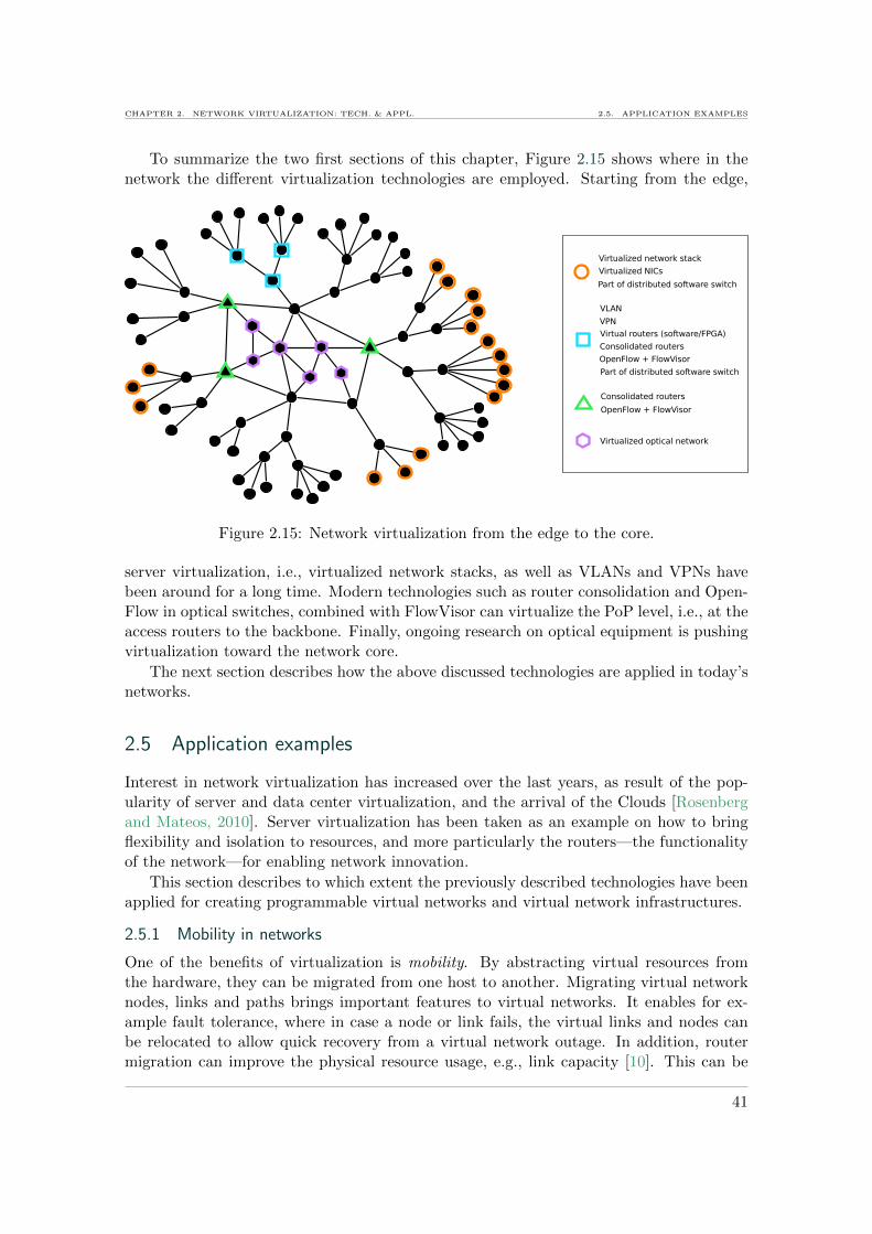
CHAPTER 2. NETWORK VIRTUALIZATION: TECH. & APPL. 2.5. APPLICATION EXAMPLES
To summarize the two first sections of this chapter, Figure 2.15 shows where in thenetwork the different virtualization technologies are employed. Starting from the edge,
Figure 2.15: Network virtualization from the edge to the core.
server virtualization, i.e., virtualized network stacks, as well as VLANs and VPNs havebeen around for a long time. Modern technologies such as router consolidation and Open-Flow in optical switches, combined with FlowVisor can virtualize the PoP level, i.e., at theaccess routers to the backbone. Finally, ongoing research on optical equipment is pushingvirtualization toward the network core.
The next section describes how the above discussed technologies are applied in today’snetworks.
2.5 Application examples
Interest in network virtualization has increased over the last years, as result of the pop-ularity of server and data center virtualization, and the arrival of the Clouds [Rosenbergand Mateos, 2010]. Server virtualization has been taken as an example on how to bringflexibility and isolation to resources, and more particularly the routers—the functionalityof the network—for enabling network innovation.
This section describes to which extent the previously described technologies have beenapplied for creating programmable virtual networks and virtual network infrastructures.
2.5.1 Mobility in networks
One of the benefits of virtualization is mobility. By abstracting virtual resources fromthe hardware, they can be migrated from one host to another. Migrating virtual networknodes, links and paths brings important features to virtual networks. It enables for ex-ample fault tolerance, where in case a node or link fails, the virtual links and nodes canbe relocated to allow quick recovery from a virtual network outage. In addition, routermigration can improve the physical resource usage, e.g., link capacity [10]. This can be
41

2.5. APPLICATION EXAMPLES CHAPTER 2. NETWORK VIRTUALIZATION: TECH. & APPL.
required in the following situation. As virtual networks can be dynamically created, atsome moment the combination of all the virtual networks on the physical network may notbe optimal. To cope with this issue, in [Yu et al., 2008], the authors propose to migratevirtual paths, to improve virtual network embedding and re-balance the mapping of virtualnetworks on the substrate. Figure 2.16 illustrates this concept, where virtual networks 1
1) Allocation
request
2) Migration
A
C
B
D
E
F
H
G 800 Mb/s
400 Mb/s
1000 Mb/s
Virtual network 2
Virtual network 3
Virtual network 1
Figure 2.16: Migration of virtual routers for improving the virtual network embedding.
and 2 are allocated and running on a physical substrate network with 1000 Mb/s links.Virtual network 3 cannot be allocated as it requests a bandwidth of 800 Mb/s on eachlink. In this case, a migration of the virtual router from the physical substrate node D tonode F can solve the problem. After the migration, virtual network 3 can be allocated onthe physical substrate nodes A, C, D, F and G.In this case, a re-organization of virtual resources can allow more virtual networks to beallocated and to use the physical resources more efficiently. Besides, the reorganizationcould be made to save energy, by minimizing the dispersion of virtual routers on the phys-ical infrastructure.In addition, Yu et al. propose to split virtual paths that require an amount of bandwidththat is not available on any physical path [Yu et al., 2008]. A fraction of the virtual pathcan for example be migrated to another physical path to optimize the allocation. A migra-tion algorithm is proposed to take such decisions on virtual network reallocations. As anexample, VROOM (Virtual ROuters On the Move) allows live migration of virtual routerswithout incurring an important performance impact on the running network [Wang et al.,2008]. The migration process is as follows. First, routing messages are tunneled to thenew host where the virtual router control plane is then migrated. The data plane keepsrunning on the initial host, while being copied to the new host. Second, after all traffic hasbeen redirected to the new host, the data plane is disabled and removed from the initialhost. Hence using VROOM, a virtual link allocated over a path containing migratingvirtual routers, appears to the user as a continuous service.
2.5.2 Research and experimentation
Multiple research initiatives are presently attempting to re-architecture Internet at differ-ent levels. In Europe, the Future Internet initiative [FI] aims at addressing challenges suchas mobility, reconfigurability, extensibility, flexibility, business value and energy efficiency,to make the Internet sustainable. These challenges emerged especially from the fact thatthe Internet is no longer only a communication facility, but an infrastructure to host and
42
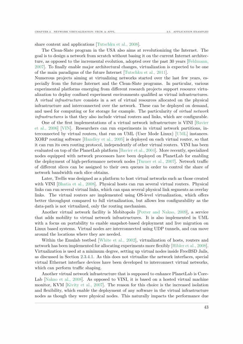
CHAPTER 2. NETWORK VIRTUALIZATION: TECH. & APPL. 2.5. APPLICATION EXAMPLES
share content and applications [Tutschku et al., 2008].
The Clean-Slate program in the USA also aims at revolutionizing the Internet. Thegoal is to design a network from scratch without basing it on the current Internet architec-ture, as opposed to the incremental evolution, adopted over the past 30 years [Feldmann,2007]. To finally enable major architectural changes, virtualization is expected to be oneof the main paradigms of the future Internet [Tutschku et al., 2011].Numerous projects aiming at virtualizing networks started over the last few years, es-pecially from the future Internet and the Clean-Slate programs. In particular, variousexperimental platforms emerging from different research projects support resource virtu-alization to deploy confined experiment environments qualified as virtual infrastructures.A virtual infrastructure consists in a set of virtual resources allocated on the physicalinfrastructure and interconnected over the network. These can be deployed on demand,and used for computing or for storage for example. The particularity of virtual networkinfrastructures is that they also include virtual routers and links, which are configurable.
One of the first implementations of a virtual network infrastructure is VINI [Bavieret al., 2006] [VIN]. Researchers can run experiments in virtual network partitions, in-terconnected by virtual routers, that run on UML (User Mode Linux) [UML] instances.XORP routing software [Handley et al., 2005] is deployed on each virtual router, so thatit can run its own routing protocol, independently of other virtual routers. VINI has beenevaluated on top of the PlanetLab platform [Bavier et al., 2004]. More recently, specializednodes equipped with network processors have been deployed on PlanetLab for enablingthe deployment of high-performance network nodes [Turner et al., 2007]. Network trafficof different slices can be assigned to their own queues in order to control the share ofnetwork bandwidth each slice obtains.
Later, Trellis was designed as a platform to host virtual networks such as those createdwith VINI [Bhatia et al., 2008]. Physical hosts can run several virtual routers. Physicallinks can run several virtual links, which can span several physical link segments as overlaylinks. The virtual routers are implemented using OS-level virtualization, which offersbetter throughput compared to full virtualization, but allows less configurability as thedata-path is not virtualized, only the routing mechanism.
Another virtual network facility is Mobitopolo [Potter and Nakao, 2009], a servicethat adds mobility to virtual network infrastructures. It is also implemented in UMLwith a focus on portability to enable snapshot-based deployment and live migration onLinux based systems. Virtual nodes are interconnected using UDP tunnels, and can movearound the locations where they are needed.
Within the Emulab testbed [White et al., 2002], virtualization of hosts, routers andnetwork has been implemented for allocating experiments more flexibly [Hibler et al., 2008].Virtualization is used at a minimum degree, setting up virtual nodes inside FreeBSD Jails,as discussed in Section 2.3.4.1. As this does not virtualize the network interfaces, specialvirtual Ethernet interface devices have been developed to interconnect virtual networks,which can perform traffic shaping.
Another virtual network infrastructure that is supposed to enhance PlanetLab is Core-Lab [Nakao et al., 2008]. As opposed to VINI, it is based on a hosted virtual machinemonitor, KVM [Kivity et al., 2007]. The reason for this choice is the increased isolationand flexibility, which enable the deployment of any software in the virtual infrastructurenodes as though they were physical nodes. This naturally impacts the performance due
43

2.5. APPLICATION EXAMPLES CHAPTER 2. NETWORK VIRTUALIZATION: TECH. & APPL.
to heavier procedures to access the hardware. However, as the technology is promisingand expected to improve, this solution may be more advantageous for enabling networkinnovations.
Virtualizing production network infrastructures creates a new business model. Asdescribed in [Feamster et al., 2007], infrastructure providers are different from serviceproviders. The former run the physical network equipments, while the latter lease virtualslices from the infrastructure. This idea is developed in [Schaffrath et al., 2009] in thecontext of virtualizing the infrastructure to enable network innovation. The authors pro-pose to layer the network architecture horizontally. Each layer is managed by a differententity, namely physical infrastructure providers and a virtual network providers, as wellas a virtual network operators and a service providers. Each stakeholder takes a differentbusiness role. While the physical provider operates the equipment, the virtual providercreates the virtual network infrastructure and leases it to a virtual network operator. Thelatter configures it for specific service providers. In such a layered model, a virtual networkoperator can individually configure a network, deploy anything and innovate. A prototypeof such an infrastructure service has been implemented using Xen and Click on commodityservers.
Shadownet [Chen et al., 2009] is yet another platform that enables to dynamicallycreate logical network topologies. As opposed to the previously described virtual infras-tructures, Shadownet nodes can be allocated on hardware network devices that featurepartitioning (e.g., Juniper logical routers [Kolon, 2004]). Virtual links are establishedusing VLAN and VPN technologies. The primary goal of Shadownet is to enable thedeployment of new tools directly on a production network made of slices of real resources.
Projects such as 4WARD [4WA] and SAIL [SAI] investigate network virtualization forprovisioning virtual networks, e.g., in Clouds and distributed data-centers.Within the GENI project [GEN], network virtualization is implemented at several levels.As an example, FlowVisor [Sherwood et al., 2010] is used to virtualize the network intoslices and allow individual OpenFlow experiments. Moreover, some optical nodes withinthe GENI experimentation facility allow virtualization with OFDM/OFDMA as describedin Section 2.3.6.
One of the first all-optical virtualized testbeds is currently being developed withinGEYSERS project, which aims at virtualizing the Internet core [4] [GEY]. The joint pro-visioning of end hosts and end-to-end links enables to dimension the network performanceexactly to the needs of applications and provides them the network as a service.
Following the described results of research, some parts of the network virtualizationtechnologies have moved to production platforms, in particular to the Clouds.
2.5.3 Virtualization in production networks and Clouds
Clouds are distributed infrastructures that provide virtual computing and storage nodeson demand, as a service [Rosenberg and Mateos, 2010]. While research starts virtualizingthe optical network, production platforms virtualize the network, especially at the edges,for interconnecting virtual machines. Virtualized data centers are for example frequentlyinterconnected by virtual networks in today’s production platforms. Cloud providers, suchas Amazon [AMA], use common server virtualization technologies with a managementframework to deploy and configure virtual machines over a distributed infrastructure.Management operations in Clouds also include migration, snapshot creation, backups,
44

CHAPTER 2. NETWORK VIRTUALIZATION: TECH. & APPL. 2.6. POSITIONING OF THE THESIS
etc., as discussed above.Examples of middleware for setting up and managing Clouds include VMware
vSphere [VSP], Eucalyptus [EUC] and OpenNebula [NEB]. In vSphere ESXi servers,virtual machines are interconnected by vSwitches inside a host. A distributed switch,vDS (discussed in Section 2.4.3), spans over several physical servers to interconnect vir-tual machines of different vSwitches. Virtual machine’s network interfaces can be groupedinto portgroups that can be configured with QoS attributes such as average- and peak-bandwidth, and burst size. Hence basic traffic control can be set up between and insidevirtual infrastructures.Eucalyptus is a private Cloud or data center solution, that integrates different hypervi-sors, like Xen, KVM, VMware vSphere ESX/ESXi [EUC]. It can also be interfaced withAmazon’s EC2 public Cloud service [AMA] into a hybrid Cloud. Traffic isolation of differ-ent virtual machines can be performed through VLAN security groups. While the goal isnot to isolate performance, classical VLAN priority mechanisms can provide basic trafficcontrol features. Also, the traffic shaping mechanisms available on the hosts, e.g., LinuxTraffic Control on Xen and KVM, or shaping on ESXi servers can be used to controlvirtual machine traffic. The same features are exposed by OpenNebula, which is also aprivate Cloud solution [NEB]. In addition, it can be deployed as a public Cloud using theOGF Open Cloud Computing Interface (OCCI) [OCC].
The example of Clouds emphasizes the need for network virtualization, since Cloudsare already running production platforms. They need a virtualized network, so that vir-tual machines in virtual infrastructures can enjoy isolated, programmable networks, withcustomizable and guaranteed performance. In fact, the network should also become aservice within the Clouds.
2.6 Positioning of the thesis
Among the different network virtualization technologies, described in this chapter, weidentify some open issues, that currently prevent virtualization from being implementedin production networks. These are in particular related to a lack of performance guaranteesinside virtual networks that share a physical infrastructure. We summarize these issuesas follows:
— Most of existing technologies virtualize only the control plane of network devices,i.e., the routing. Yet, for providing performance guarantees to virtual networks, thedata plane has to be fully virtualized since it is to the way to control the amount ofresources attributed to each virtual network.
— The technologies that virtualize the data plane share only ports among virtual net-work devices. However, port capacity is not the only criterion for performanceguarantees and QoS in a virtual network. The buffer sizes are also of great impor-tance.
— The configurability of virtual networks is limited to the routing control plane. Nev-ertheless, for configuring QoS per virtual network, the forwarding control and hencethe packet scheduling mechanisms must also be configurable.
45

2.7. CONCLUSIONS CHAPTER 2. NETWORK VIRTUALIZATION: TECH. & APPL.
— Most technologies share the resources without constraints, i.e., the amount eachresource conferred to a virtual network can not be configured. This does not provideperformance guarantees to a virtual network.
These issues motivated us to i) virtualize all the resources of the network data plane,ii) enable the configuration of forwarding and packet scheduling in virtual networks, andiii) parametrize the virtualization function with the amount of each resource the virtualnetwork should obtain, when sharing the network. Hence, we propose to virtualize thedifferent resources of the data plane with a new parameter specifying the capacities of allthe virtual resources, also worth nothing in a formal way as:
Vs: Resource, Set of capacities → Set of virtual resources with specific capacities
In particular, we propose to virtualize the switching fabric of network devices, to sharethe ports and buffers between virtual switches, and to enable each virtual switch to haveits own scheduling mechanism. As an example, the above function applies respectively inthe following ways to share ports and buffers:
Vs: Port, Set of capacities → Set of virtual ports with specific capacities
Vs: Buffer, Set of buffer sizes → Set of virtual buffers with specific sizes
Throughout this manuscript, we propose different technologies for virtualizing theresources of the data plane, controlling the parametrized sharing of resources among virtualnetworks, and enabling the configuration of scheduling mechanisms at the data plane level.
2.7 Conclusions
Traditionally, networks have been virtualized to offer connectivity independently to dif-ferent groups of users, with the help of technologies like VLAN and VPN. However, toprovide virtual networks with the same configurable functionality as physical networks,the network devices and their functionality also need to be virtualized. This has engagedresearch mainly on how to build virtual routers and programmable switches. It is crucial,to control the sharing of the physical resources by virtual routers, in order to provideeach virtual network with performance guarantees. In addition, each virtual router shouldenable the configuration of fine-grained QoS, to be adaptable to application requirements.For providing virtual routers with this feature and make them behave like physical oneswith full functionality and performance guarantees, virtualization needs to take place atlayer 2, exposing routing and switching functionality to a virtual device. The first steptowards building such virtualized networks is analyzing and comparing mechanisms thatcan implement virtualization at layer 2—the data plane. This is the subject of the nextchapter, where a virtual router with a virtualized data-plane is prototyped and evaluated.
46

3Analysis and evaluation of the impact ofvirtualization mechanisms on communicationperformance
3.1 Introduction
3.2 Virtualizing the data plane
3.2.1 Virtual router design
3.2.2 Available technologies
3.2.3 Virtualized data path
3.3 Performance evaluation and analysis
3.3.1 Metrics
3.3.2 Experimental setup
3.3.3 Sending and receiving performance
3.3.4 Forwarding performance
3.3.5 Discussion
3.4 Comparison to previous results and follow up
3.5 Conclusion
The work presented in this chapter has been published and awarded as a top paperat the International Conference on Networking and Services (ICNS) in 2009 [7],at the Linux Symposium 2009 [9] and at the International Journal On Advances inIntelligent Systems 2009 [2]. In addition, a research report has been published [11].
Abstract. Virtualizing the network brings new challenges, especially addressing thepotential performance overhead induced by the virtualization layer. For quantifying these,this chapter presents a performance study, whose main contributions are:
Virtua
lizationPerformance
• An extensive analysis and comparison of technologies thatenable the virtualization of the network data plane;
• A prototype implementation of a virtual software routeron commodity server hardware; and
• The evaluation of the virtual end-host and router perfor-mance in terms of throughput, packet loss and processingpower under various conditions.
47

3.1. INTRODUCTION CHAPTER 3. IMPACT OF VIRTUALIZATION ON COMM. PERF.
3.1 Introduction
A wide variety of virtualization technologies, e.g., VMware [VMW], Xen [Barham et al.,2003], KVM [Kivity et al., 2007] are commonly used nowadays for virtualizing servers. In-troducing these to the network offers great flexibility, since virtualizing links and routers,i.e., connectivity and functionality, allows running and configuring different virtual net-works independently on the same physical infrastructure. Virtual routers can executecustomized routing protocols that affect only their virtual network environment. Hence,a virtual network is an ideal environment for experimentation ‘in the wild’ because it canbe deployed in parallel with a production network without damaging the latter.
As stated in the previous chapters, virtualization was initially made available to end-hosts to virtualize resources such as storage and computing. In this chapter, virtualizationis pushed one step farther into the network. A virtual router prototype is built in soft-ware, and evaluated in the edge network. The precondition while designing the edge virtualrouter—intended for experimentation—is to have full functional isolation from other vir-tual routers. For realizing this, it has to have a virtual control-plane and a virtual dataplane, so that packets from different virtual routers can take different customizable for-warding paths. The goal is to obtain a fully programmable virtual router, able to controlrouting and forwarding of the traffic in virtual infrastructures (detailed in Chapter 5).
However, virtualizing the data plane adds a layer of processing between the hardwareand the system. This layer, responsible for virtualizing packet I/O mechanisms, is costlyas described in the previous chapter. In addition, the layer controls the resource sharingand isolation between different virtual routers, so that the activity of one virtual routerdoes not affect any other virtual router. For having better insight into these issues, inthe next section we analyze the current technical solutions that allow virtualizing thenetwork data plane. Based on this analysis, a virtual router prototype with a virtualizeddata plane is implemented. Its properties and potential in terms of network performancelike throughput, packet loss, latency and the induced processing cost are evaluated inSection 3.3. Finally, Section 3.4 compares these results with related studies.
The results presented in this chapter were obtained over a large period of time, evalu-ating progressively different releases of virtualization software as they were launched—firstXen 3.1, then Xen 3.2 and later KVM 84—to have an overview of the technological eval-uation [7] [9] [2]. A summary of all performance evaluations of this chapter is given inTable 3.1.
3.2 Virtualizing the data plane
Our primary concern in designing of a virtualized network is the ability to configure routingand forwarding, e.g., protocols as well as specific operations on packets, such as filtering,queueing, scheduling, etc., on a per virtual network basis. For addressing this concern, itis necessary to virtualize the data plane.
3.2.1 Virtual router design
To evaluate the performance of communication mechanisms in virtual networks, we startby building a virtual router in software, with a virtualized data plane. We then evaluateits performance. This section describes its design requirements.
48
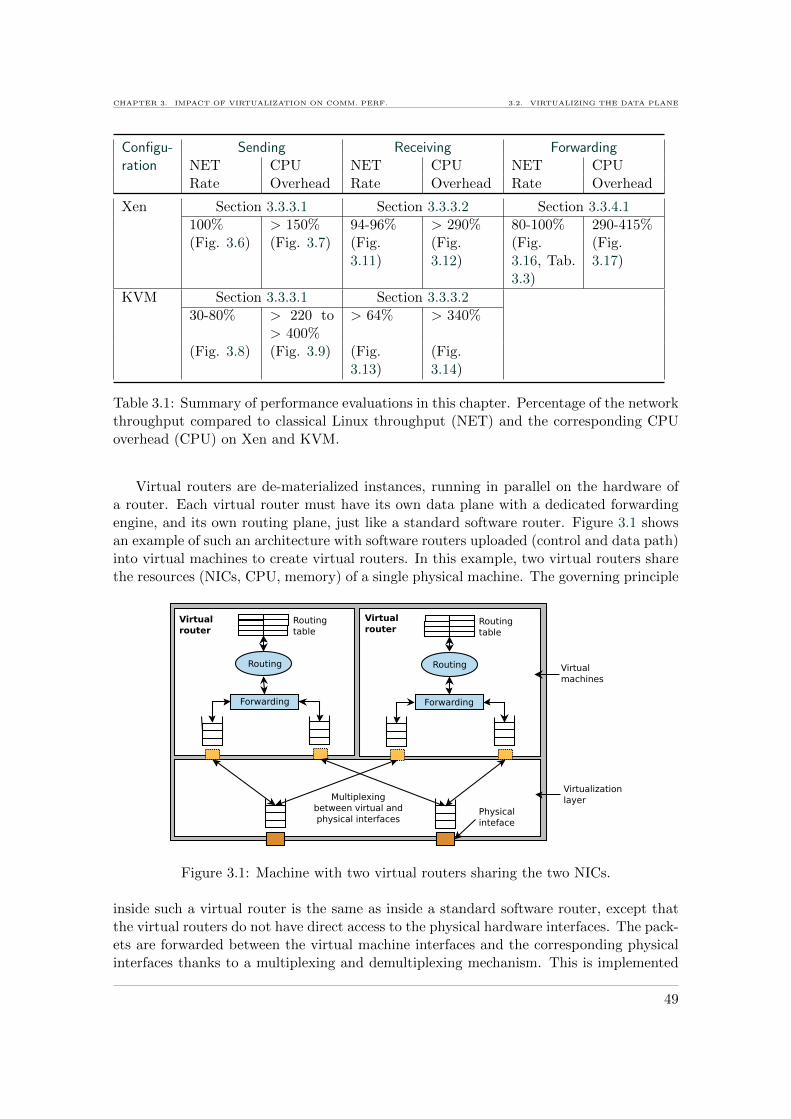
CHAPTER 3. IMPACT OF VIRTUALIZATION ON COMM. PERF. 3.2. VIRTUALIZING THE DATA PLANE
Configu- Sending Receiving Forwardingration NET CPU NET CPU NET CPU
Rate Overhead Rate Overhead Rate Overhead
Xen Section 3.3.3.1 Section 3.3.3.2 Section 3.3.4.1100% > 150% 94-96% > 290% 80-100% 290-415%(Fig. 3.6) (Fig. 3.7) (Fig.
3.11)(Fig.3.12)
(Fig.3.16, Tab.3.3)
(Fig.3.17)
KVM Section 3.3.3.1 Section 3.3.3.230-80% > 220 to
> 400%> 64% > 340%
(Fig. 3.8) (Fig. 3.9) (Fig.3.13)
(Fig.3.14)
Table 3.1: Summary of performance evaluations in this chapter. Percentage of the networkthroughput compared to classical Linux throughput (NET) and the corresponding CPUoverhead (CPU) on Xen and KVM.
Virtual routers are de-materialized instances, running in parallel on the hardware ofa router. Each virtual router must have its own data plane with a dedicated forwardingengine, and its own routing plane, just like a standard software router. Figure 3.1 showsan example of such an architecture with software routers uploaded (control and data path)into virtual machines to create virtual routers. In this example, two virtual routers sharethe resources (NICs, CPU, memory) of a single physical machine. The governing principle
Figure 3.1: Machine with two virtual routers sharing the two NICs.
inside such a virtual router is the same as inside a standard software router, except thatthe virtual routers do not have direct access to the physical hardware interfaces. The pack-ets are forwarded between the virtual machine interfaces and the corresponding physicalinterfaces thanks to a multiplexing and demultiplexing mechanism. This is implemented
49

3.2. VIRTUALIZING THE DATA PLANE CHAPTER 3. IMPACT OF VIRTUALIZATION ON COMM. PERF.
in an intermediate layer located between the hardware and the virtual machines. As aconsequence, additional computing is required in this design, whose impact on the networkperformance needs to be analyzed.
We decide to implement this preliminary virtual router design, using common virtu-alization techniques running on commodity hardware, which enable to virtualize the dataplane. This choice is made for the sake of programmability and portability to any com-puting platform. Besides, today’s general purpose hardware is powerful enough to makerouting and forwarding in software a quite promising approach, at least at the edge of anetwork.
For implementing such a virtual router prototype, different available technologies areinvestigated in the following.
3.2.2 Available technologies
Virtualizing the data plane means having separate packet queues, forwarding tables, rout-ing tables and routing daemons in each virtual router. Hence, while choosing an appro-priate technology for virtualizing commodity hardware, our constraints are 1) that eachvirtual machine must be able to run its own OS with its own kernel, and 2) that eachvirtual machine has its own hardware abstractions, such as packet queues that can beconfigured. These constraints limit the choice of the technology to full- or paravirtualiza-tion (this choice results from the comparison of the different virtualization technologies inSection 2.3.4 of Chapter 2). Both enable virtualization to take place at the lowest levelin software, directly above the hardware, so that each virtual machine performs networkoperations down to layer 2 of the OSI model.
The most popular full virtualization technologies are KVM [Kivity et al., 2007] andVMware [VMW], but also VirtualBox [VBX], while the mostly used paravirtualizationtechnology is Xen. These technologies are compared in Figure 3.2, according to theirlevel of configurability, and their I/O optimizations or network performance expectation.KVM offers great flexibility for experimentation, as it uses a Linux kernel that enables
Configurability/Flexibility
Network I/O
Optimizations
VMware Server
Xen
KVM + virtio
KVM
Qemu
VirtualBox
VMware ESXi
Figure 3.2: Comparison of full- and paravirtualization technologies.
full programmability. However, due to the emulation of the network devices, performanceis potentially rather low. Yet, with the appearance of the virtio [Russell, 2008] tools,
50

CHAPTER 3. IMPACT OF VIRTUALIZATION ON COMM. PERF. 3.2. VIRTUALIZING THE DATA PLANE
consisting of a set of virtual I/O drivers, KVM became, as well, able to perform paravir-tualization. VMware is probably one of the most optimized full virtualization technologyand gives good network performance according to some preliminary tests we performed onESXi and VMware Server. But it is less configurable as it is a closed system, and henceless adapted to our experimental context. VirtualBox in turn was designed at a first placefor desktop virtualization, hence it may not be adapted to high network loads.
As both, Xen and KVM, combine promising performance with a high configurability,we retain these for building the virtual router prototype, analyze them further and evaluatethem.
3.2.3 Virtualized data path
In this section, we examine the data path that packets take throughout a virtual routerfor each of the two technologies, Xen and KVM.
3.2.3.1 Data path in Xen
The virtual machines in Xen access the network hardware through the virtualization layer,called the virtual machine monitor or the hypervisor. Each domU has a virtual interfacefor each physical network interface it wants to use on the physical machine. This virtualinterface is accessed via a split-device driver composed of two parts, the frontend driver indomU and the backend driver in dom0 [Chisnall, 2007]. Figure 3.3 illustrates these com-ponents, and the path followed by a network packet sent from a virtual machine residinginside a domU to the physical NIC. The memory page where a packet resides in the domU
Figure 3.3: Path of a network packet with Xen, from a domU to the NIC.
kernel is either mapped to dom0 or the packet is copied to a segment of shared memoryby the Xen hypervisor from where it is transmitted to dom0. Inside dom0, packets arebridged (path 1) or routed (path 2) between the virtual interfaces and the physical ones.The reception of packets on a domU is similar. To receive a packet, domU gives a grantto dom0 so that dom0 can access the grant page and copy the packet to domU’s kernel
51
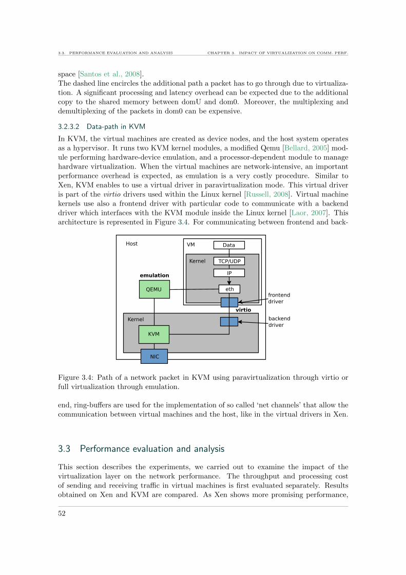
3.3. PERFORMANCE EVALUATION AND ANALYSIS CHAPTER 3. IMPACT OF VIRTUALIZATION ON COMM. PERF.
space [Santos et al., 2008].The dashed line encircles the additional path a packet has to go through due to virtualiza-tion. A significant processing and latency overhead can be expected due to the additionalcopy to the shared memory between domU and dom0. Moreover, the multiplexing anddemultiplexing of the packets in dom0 can be expensive.
3.2.3.2 Data-path in KVM
In KVM, the virtual machines are created as device nodes, and the host system operatesas a hypervisor. It runs two KVM kernel modules, a modified Qemu [Bellard, 2005] mod-ule performing hardware-device emulation, and a processor-dependent module to managehardware virtualization. When the virtual machines are network-intensive, an importantperformance overhead is expected, as emulation is a very costly procedure. Similar toXen, KVM enables to use a virtual driver in paravirtualization mode. This virtual driveris part of the virtio drivers used within the Linux kernel [Russell, 2008]. Virtual machinekernels use also a frontend driver with particular code to communicate with a backenddriver which interfaces with the KVM module inside the Linux kernel [Laor, 2007]. Thisarchitecture is represented in Figure 3.4. For communicating between frontend and back-
Figure 3.4: Path of a network packet in KVM using paravirtualization through virtio orfull virtualization through emulation.
end, ring-buffers are used for the implementation of so called ‘net channels’ that allow thecommunication between virtual machines and the host, like in the virtual drivers in Xen.
3.3 Performance evaluation and analysis
This section describes the experiments, we carried out to examine the impact of thevirtualization layer on the network performance. The throughput and processing costof sending and receiving traffic in virtual machines is first evaluated separately. Resultsobtained on Xen and KVM are compared. As Xen shows more promising performance,
52

CHAPTER 3. IMPACT OF VIRTUALIZATION ON COMM. PERF. 3.3. PERFORMANCE EVALUATION AND ANALYSIS
it is further used for building the virtual router prototype and evaluating its forwardingrate and latency.
3.3.1 Metrics
An efficient usage of virtual machines for networking requires a certain number of non-functional properties like efficiency, fairness in resource sharing and predictability of per-formance. We define and evaluate these properties using the metrics summarized in Ta-ble 3.2.
Metric Description
Ri Throughput of virtual machine i, i ∈ [1, N ]
Raggregate
N∑i=1
Ri: aggregate throughput on all N virtual machines
Raggregate/N Effective mean throughputCi CPU cost on virtual machine i, i ∈ [1, N ]
Caggregate
N∑i=1
Ci: total CPU cost on all N virtual machines
Li Latency on virtual machine i, i ∈ [1, N ]Rclassical(T/R)) Throughput for sending/receiving on classical Linux
Rclassical(F ) Throughput for forwarding on classical Linux without virtualization
Cclassical(T ) CPU cost of sending on classical Linux
Cclassical(R) CPU cost of receiving on classical Linux
Cclassical(F ) CPU cost of forwarding on a classical Linux software router
Lclassical(F ) Latency of forwarding on a classical Linux router
Rtheoretical Theoretical data throughput on 1 Gb/s Ethernet interfaces(941 Mb/s for TCP and 952 Mb/s for UDP)
Table 3.2: Metrics for measuring network performance on a physical machine hostingN ∈ N virtual machines.
For quantifying the performance of a virtual system, we define its efficiency as theratio between its achieved metric and the the same metric achieved on a classical Linuxsystem under the same workload.
For example, we define the efficiency in terms of throughput by (1)
Ethroughput =Raggregate
Rclassical(1).
The fairness of the inter-virtual machine resource sharing is derived from the classical Jainindex [Jain et al., 1984], defined by (2).
Fairness(x) =
[N∑i=1
xi
]2
N ×N∑i=1
x2i
(2)
53

3.3. PERFORMANCE EVALUATION AND ANALYSIS CHAPTER 3. IMPACT OF VIRTUALIZATION ON COMM. PERF.
Here, N represents the number of virtual machines sharing the physical resources andxi the metric achieved by virtual machine i, for example the throughput or the CPUpercentage.
Predictability and scalability of the system are inferred by analyzing the performancebased on the number of virtual machines.
3.3.2 Experimental setup
The experiments were all executed on the French national testbed Grid’5000 that handsover full control and configuration rights on its machines to the user during a reservation[Cappello et al., 2005] [G5K]. Hence, different types of machines were installed with Linux,as well as Xen and KVM for the purpose of these experiments. For the Xen end-hostswe used IBM eServers 325, with 2 AMD Opteron 246 CPUs (2.0 GHz/1 MB) with onecore each, 2 GB of memory and a 1 Gb/s NIC. Virtual routers were deployed on IBMeServers 326m, with 2 AMD Opteron 246 CPUs (2.0GHz/1MB), with one core each, 2 GBof memory and two 1 Gb/s NICs. The experiments on KVM were executed on morerecent machines provided with hardware virtualization enabled processors. These wereDell PowerEdges 1950 with two dual-core Intel Xeon 5148 LV processors (2.33 Ghz), 8 GBof memory, and 1 Gb/s NICs. In each experiment, machines inside one LAN interconnectedby a single switch were used to avoid any additional latency or concurrent network load.
The precise software configurations used were Xen 3.1.0 and 3.2.1 with respectively themodified 2.6.18-3 and 2.6.18.8 Linux kernels. Comparative experiments were performed onKVM 84 with the Linux 2.6.29 kernel in the host system as well as in the virtual machine.With KVM, the default full virtualization (FV) with the emulated network driver, as wellas paravirtualization (PV) with the virtio driver were evaluated.
Measurement tools were iperf [IPE] for the TCP throughput, netperf [NPE] for theUDP rate, xentop and sar for the CPU utilization, and the ping utility for measuringlatency.
3.3.3 Sending and receiving performance
In the following experiments, each, sending and receiving performance for default max-imum sized (1500 Bytes) packets, was evaluated on virtual machines implemented withXen 3.1, Xen 3.2 and KVM. As some results with Xen 3.1 were not satisfying, dom0 beingthe bottleneck, a second run of the experiments on Xen 3.1 was performed, attributingmore CPU time to dom0 (up to 16 times the part attributed to a domU). This choicewas made as dom0 is in charge of forwarding all the network traffic between the physicaland the virtual interfaces. In the case of 8 virtual machines, dom0 needs to handle thetraffic of all 8 virtual machines on the physical interface, as well as on each of its virtualinterfaces. Its load is hence estimated to be 8 + 8 = 16 times higher than the load of asingle domU. This setup will be called Xen 3.1a. KVM was used either in its native fullhardware virtualization setup or using lightweight paravirtualization. The experimentswere repeated ten times and avereage results are presented.
3.3.3.1 Sending performance
In this first experiment, the TCP sending throughput on 1, 2, 4 and 8 virtual hostsinside one physical machine, as well as the corresponding CPU overhead, were evaluated.Figure 3.5 shows the test setup, for the example with two virtual machines, acting as
54

CHAPTER 3. IMPACT OF VIRTUALIZATION ON COMM. PERF. 3.3. PERFORMANCE EVALUATION AND ANALYSIS
senders from the same physical machine.
VM
VM
Physical machine under test Traffic sinks
Figure 3.5: Experimental architecture for evaluating virtual machine sending performance.
The throughput per virtual machine and the aggregate throughput with Xen are rep-resented on Figure 3.6. In both Xen configurations, 3.1 and 3.2, performance was close
0
100
200
300
400
500
600
700
800
900
1000
1domU 2domU 4domU 8domU
TC
P thro
ughput(
Mb/s
)
Ragg 3.1
Ragg 3.1a
Ragg 3.2
Ri 3.1
Ri 3.1a
Ri 3.2
Rtheoretical
Rtheoretical/N
Figure 3.6: TCP Sending throughput on respectively 1, 2, 4 or 8 domUs with Xen versions3.1 and 3.2.
to classical Linux throughput Rclassical(T/R) = 938 Mb/s. In 3.1a and 3.2 setups, theaggregated throughput obtained by all the virtual machines was barely higher than on3.1. We conclude that in the three cases (3.1, 3.1a, 3.2), the system is efficient and pre-dictable, in terms of sending throughput. In addition, the sharing is fair as the throughputper virtual machine corresponds to the fair share of the available bandwidth of the link(Rtheoretical/N) and the fairness index is equal to 1.
The associated average CPU utilization for each Xen guest domain is represented inFigure 3.7. For a single domU, around half the processing power of the two CPUs (i.e.,100%) was used in the three setups (Xen 3.1, 3.1a and 3.2), whereas on a native Linuxsystem without virtualization, we measured that only Cclassical(E) = 64% of a single CPUwas in use running the same network benchmark. In the experiment with 8 domUs, theCPUs were used at over 140%. The overall CPU overhead did not differ much between Xen3.1 and 3.2 setups. However, by increasing dom0’s CPU weight (setup 3.1a), the overall
55

3.3. PERFORMANCE EVALUATION AND ANALYSIS CHAPTER 3. IMPACT OF VIRTUALIZATION ON COMM. PERF.
0
20
40
60
80
100
120
140
160
180
200
3.1 3.1a1domU
3.2 3.1 3.1a2domU
3.2 3.1 3.1a4domU
3.2 3.1 3.1a8domU
3.2
Avera
ge C
PU
usage (
%)
Number of domUs
Cdom0Cdom1Cdom2Cdom3Cdom4Cdom5Cdom6Cdom7Cdom8
Cclassical(E)
Figure 3.7: Average utilization of the two CPUs during TCP sending on 1, 2, 4 or 8 domUswith Xen.
CPU cost also increased while improving the throughput insignificantly. We notice thateven though virtualization introduced a processing overhead, two processors like the onesused in these experiments achieved a throughput equivalent to the maximum theoreticalthroughput on 8 concurrent virtual machines, sending TCP flows of default maximum-sized packets on a 1 Gb/s link. Here, the fairness index was close to 1, bandwidth andCPU time were fairly shared between the different domUs.
0
100
200
300
400
500
600
700
800
900
1000
1 VM 2 VM 4 VM 8 VM
TC
P thro
ughput(
Mb/s
)
Ragg PV
Ragg FV
Ri PV
Ri FV
Rtheoretical
Rtheoretical/N
Figure 3.8: TCP Sending throughput on 1, 2, 4 or 8 virtual machines with KVM 84 usingparavirtualization (PV) or full virtualization (FV).
The same experiment was executed on virtual machines implemented with KVM. KVM
56
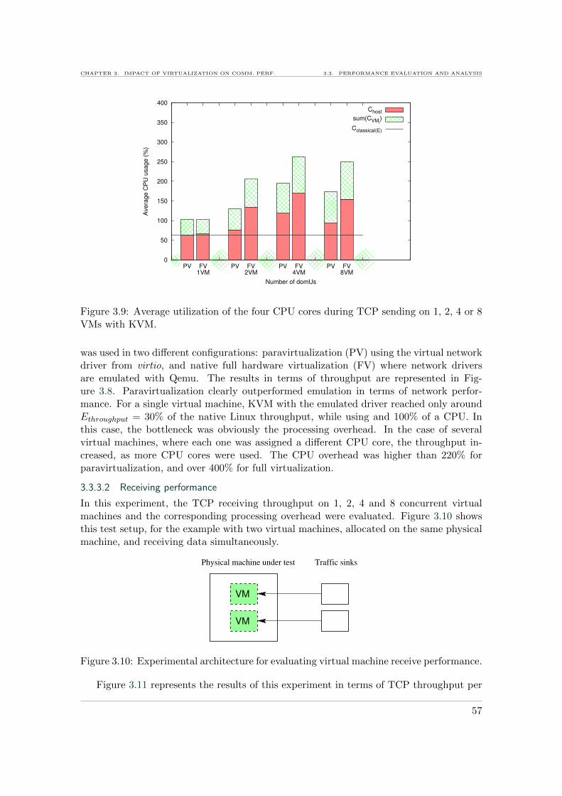
CHAPTER 3. IMPACT OF VIRTUALIZATION ON COMM. PERF. 3.3. PERFORMANCE EVALUATION AND ANALYSIS
0
50
100
150
200
250
300
350
400
PV FV1VM
PV FV2VM
PV FV4VM
PV FV8VM
Avera
ge C
PU
usage (
%)
Number of domUs
Chost
sum(CVMi)
Cclassical(E)
Figure 3.9: Average utilization of the four CPU cores during TCP sending on 1, 2, 4 or 8VMs with KVM.
was used in two different configurations: paravirtualization (PV) using the virtual networkdriver from virtio, and native full hardware virtualization (FV) where network driversare emulated with Qemu. The results in terms of throughput are represented in Fig-ure 3.8. Paravirtualization clearly outperformed emulation in terms of network perfor-mance. For a single virtual machine, KVM with the emulated driver reached only aroundEthroughput = 30% of the native Linux throughput, while using and 100% of a CPU. Inthis case, the bottleneck was obviously the processing overhead. In the case of severalvirtual machines, where each one was assigned a different CPU core, the throughput in-creased, as more CPU cores were used. The CPU overhead was higher than 220% forparavirtualization, and over 400% for full virtualization.
3.3.3.2 Receiving performance
In this experiment, the TCP receiving throughput on 1, 2, 4 and 8 concurrent virtualmachines and the corresponding processing overhead were evaluated. Figure 3.10 showsthis test setup, for the example with two virtual machines, allocated on the same physicalmachine, and receiving data simultaneously.
VM
VM
Physical machine under test Traffic sinks
Figure 3.10: Experimental architecture for evaluating virtual machine receive performance.
Figure 3.11 represents the results of this experiment in terms of TCP throughput per
57

3.3. PERFORMANCE EVALUATION AND ANALYSIS CHAPTER 3. IMPACT OF VIRTUALIZATION ON COMM. PERF.
domU and aggregate throughput with Xen. We notice that the aggregate throughput
0
100
200
300
400
500
600
700
800
900
1000
1domU 2domU 4domU 8domU
TC
P thro
ughput(
Mb/s
)
Ragg 3.1
Ragg 3.1a
Ragg 3.2
Ri 3.1
Ri 3.1a
Ri 3.2
Rtheoretical
Rtheoretical/N
Figure 3.11: TCP Receiving throughput on respectively 1, 2, 4 or 8 domUs with Xenversions 3.1 and 3.2.
decreased slightly according to the number of virtual machines on Xen 3.1. It reachedonly 882 Mb/s on two domUs and only 900 Mb/s on a set of 8 concurrent domUs, whichcorresponds to about 96% of throughput Rclassical(T/R) = 938 Mb/s on a classical Linuxsystem. Efficiency Ethroughput varied between 0.96 for 8 domUs and 0.94 for two domUs.By changing the scheduler parameters (Xen 3.1a), we managed to improve the aggregatethroughput to reach about 970 Mb/s on 8 virtual machines, thus making the systemefficient.
Besides, the sharing of the bandwidth between the domUs in Xen 3.1 was increasinglyunfair when incrementing the number of domUs. This problem was related to an unfairtreatment of the events (domUs created later got less chance to get their events treatedthan those created earlier, as in each round, the scheduler started with the first createddomU, even if a round was interrupted before all domUs were served). It was fixed inXen 3.2 by modifying the scheduling algorithm [Ongaro et al., 2008]. Our solution thatprovided dom0 with more CPU time simply (3.1a setup) allowed also to improve fairnessin Xen 3.1 by giving dom0 enough time to treat all the events before the scheduler ran outof credits and started switching unnecessarily between dom0 and domUs. The resultingfair resource sharing made performance much more predictable. The measured aggregatereceiving throughput in Xen 3.2 was more similar to the Xen 3.1a results with the modifiedscheduler parameters. The throughput increased by about 6% compared to the default3.1 version. Figure 3.12 gives the CPU time distribution among the guest domains. Thetotal CPU cost of the system varied between 140% and 150% in the default Xen 3.1and 3.2 versions, which represents an important overhead (over 290%). Indeed, on aLinux system which is not virtualized network reception at maximum speed takes onlyCclassical(R) = 48% of the CPU using the same benchmark. We notice that on the defaultXen 3.1, the efficiency in terms of throughput decreased, while the available CPU time
58

CHAPTER 3. IMPACT OF VIRTUALIZATION ON COMM. PERF. 3.3. PERFORMANCE EVALUATION AND ANALYSIS
0
20
40
60
80
100
120
140
160
180
200
3.1 3.1a1domU
3.2 3.1 3.1a2domU
3.2 3.1 3.1a4domU
3.2 3.1 3.1a8domU
3.2
Avera
ge C
PU
usage (
%)
Number of domUs
Cdom0Cdom1Cdom2Cdom3Cdom4Cdom5Cdom6Cdom7Cdom8
Cclassical(E)
Figure 3.12: Average utilization of the two CPUs during TCP receiving on 1, 2, 4 or 8domUs.
was not entirely consumed. Also, the distribution of the CPU time consumption amongthe domUs followed the same unfairness pattern than for the throughput. This shows thatthe virtual machine scheduler on the CPU looses efficiency when stressed with networking.The fairness index decreased to only 0.46 on 8 concurrent domUs on Xen 3.1 because ofthe described scheduling problem.
0
100
200
300
400
500
600
700
800
900
1000
1 VM 2 VM 4 VM 8 VM
TC
P thro
ughput(
Mb/s
)
Ragg PV
Ragg FV
Ri PV
Ri FV
Rtheoretical
Rtheoretical/N
Figure 3.13: TCP Receiving throughput on 1, 2, 4 or 8 virtual machines with KVM 84using paravirtualization (PV) and full virtualization (FV).
In summary, our proposal to readjust the scheduler parameters (setup 3.1a) improvedfairness in Xen 3.1, but increased CPU consumption. The Xen 3.2 version showed sim-
59

3.3. PERFORMANCE EVALUATION AND ANALYSIS CHAPTER 3. IMPACT OF VIRTUALIZATION ON COMM. PERF.
0
50
100
150
200
250
300
350
400
PV FV1VM
PV FV2VM
PV FV4VM
PV FV8VM
Avera
ge C
PU
usage (
%)
Number of domUs
Chost
sum(CVMi)
Cclassical(E)
Figure 3.14: Average utilization of the four CPU cores during TCP receiving on 1, 2, 4 or8 virtual machines with KVM.
ilar trends, increasing throughput and removing unfairness. Moreover, CPU utilizationdecreased slightly. It was still more efficient than in Xen 3.1, showing less total CPU over-head while achieving even better throughput. We conclude that important improvementshave been implemented in Xen 3.2 to decrease the excessive dom0 CPU overhead.
In comparison, KVM using the virtualized network driver achieved very similar resultsin sending performance. Using a single CPU core, as in the case of one virtual machine,is not enough to achieve maximal Linux throughput as shows Figure 3.13. Throughputreaches only around 800 Mb/s in paravirtualization mode, and barely more than 600 Mb/sin full virtualization mode, which corresponds to an efficiency Ethroughput of around 64%.Figure 3.14 shows that the CPU overhead for receiving is slightly more important thanfor sending using virtio paravirtualization driver. This is similar to the results obtainedwith Xen 3.2, which nevertheless used between 10% and 30% less processing to achievethe same throughput. The CPU overhead corresponds to respectively 340 and 560% forachieving 100% throughput efficiency with paravirtualization and full virtualization. Inthe case of full virtualization, KVM’s receiving mechanism is more efficient than its sendingmechanism, but it still does not reach Xen’s performance, needing three of the availableCPU cores to achieve maximum Linux throughput.
3.3.4 Forwarding performance
To evaluate the forwarding performance of virtual routers, we sent UDP traffic over virtualrouters with 2 NICs, as depicted in Figure 3.15, and measured the throughput obtainedon the receiver, and the packet loss. We repeated the experiment using TCP traffic, andmeasured also throughput, as well as latency.
For this experiment, only Xen 3.2 was used, which was the best performing technologyin the previous experiments. The results were obtained on Xen 3.2 in its default configu-ration and with an increased weight (up to 32 times the weight of a domU) for dom0 in
60

CHAPTER 3. IMPACT OF VIRTUALIZATION ON COMM. PERF. 3.3. PERFORMANCE EVALUATION AND ANALYSIS
VM
VM
Physical machine under test Traffic sinksTraffic sources
Figure 3.15: Experimental architecture for evaluating virtual machine forwarding perfor-mance.
CPU scheduling. We call this setup Xen 3.2a in the following.
3.3.4.1 Throughput and processing cost
For determining the performance of virtual routers, UDP traffic was generated with eithermaximum- (1500 bytes) or minimum- (64 bytes) sized packets over one or several virtualrouters (from 1 to 8) sharing a single physical machine. All the flows were sent at maximumrate from distinct physical machines to avoid bias. Next, end-to-end TCP throughput wasalso measured.
Figure 3.16 shows the obtained UDP bit rate with maximum-sized packets and theTCP throughput. The corresponding CPU cost is represented in Figure 3.17. Table 3.3details the UDP packet rates and the loss rates per domU with maximum- and minimum-sized packets.
0
100
200
300
400
500
600
700
800
900
1000
1domU 2domU 4domU 8domU
Ra
te (
Mb
/s)
Ragg 3.2 UDP
Ragg 3.2 TCP
Ragg 3.2a TCP
Ri UDP 3.2
Ri TCP 3.2
Ri 3.2a TCP
Rmax UDP
Rmax TCP
Rmax/N UDP
Rmax/N TCP
Figure 3.16: Receiver side throughput over 1, 2, 4 or 8 virtual routers with Xen 3.2forwarding 1500-byte packets.
With UDP, the percentage of loss with maximum-sized packets on each virtual machinecorresponds to 1−(1/N). This means that the bandwidth is fairly shared between the vir-tual routers. The results show efficiency, the throughput corresponds to the value obtained
61

3.3. PERFORMANCE EVALUATION AND ANALYSIS CHAPTER 3. IMPACT OF VIRTUALIZATION ON COMM. PERF.
0
20
40
60
80
100
120
140
160
180
200
UDP TCP1domU
TCPa UDP TCP2domU
TCPa UDP TCP4domU
TCPa UDP TCP8domU
TCPa
Avera
ge C
PU
usage (
%)
Number of domUs
Cdom0Cdom1Cdom2Cdom3Cdom4Cdom5Cdom6Cdom7Cdom8
Cclassical(E)
Figure 3.17: CPU cost of 1, 2, 4 or 8 virtual routers with Xen 3.2 forwarding 1500-bytepackets.
1500 byte packets 64 byte packetspps/domU loss/domU pps/domU loss/domU
Classical Linux 81277 0.00 % 356494 0.06 %1 VR 81284 0 % 109685 60 %2 VR 40841 50 % 12052 96 %4 VR 20486 75 % / /8 VR 10393 87 % / /
Table 3.3: Average UDP packet-forwarding rate (pps) and loss rate per domU hosting avirtual router (VR).
on a classical Linux router Rclassical(F ) = 957 Mb/s. The aggregate UDP throughput wasin some cases a bit higher than the theoretical value due to little variation in the start timesof the different flows. Resource sharing was fair: in this case, performance is predictable.With maximum-sized packets, dom0 used an entire CPU, forwarding at maximum ratewith UDP and only 80% of the maximum throughput with TCP, having an efficiency ofEthroughput = 0.80. With minimum-sized packets on 4 or 8 virtual routers, dom0 becametoo overloaded, not being able to forward on all virtual routers anymore.
Regarding the processing of the router, dom0 used much more CPU resources than thedomUs, compared to the simple sending or receiving scenario. On a classical Linux router,we measured that the forwarding of a flow at maximum speed generated a CPU load ofCclassical(F ) =36%. However, using virtual routers inside Xen domUs generated a CPUload between 105 and 150% as shown in Figure 3.17. Hence, forwarding inside virtualmachines generates an overhead between around 290 and 415%. This high overhead isdue to the fact that it has to forward the traffic of twice as many virtual interfaces thanbefore (16 in the case of 8 virtual routers). In the case of UDP and TCP with the
62
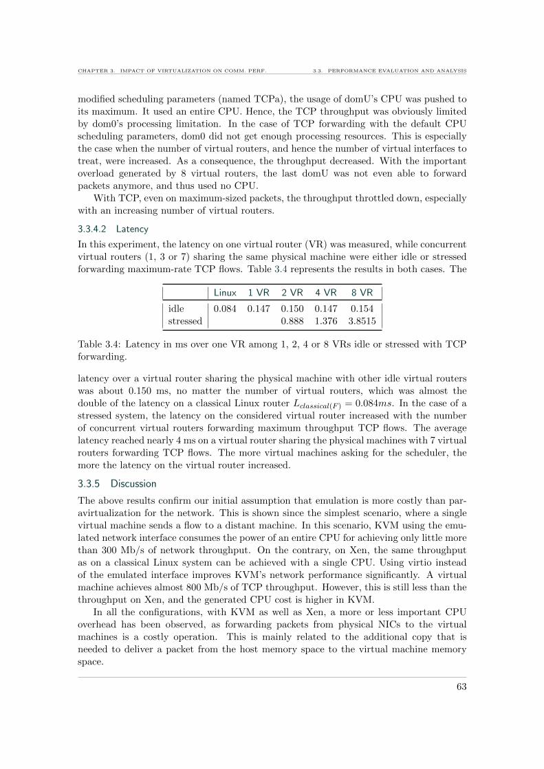
CHAPTER 3. IMPACT OF VIRTUALIZATION ON COMM. PERF. 3.3. PERFORMANCE EVALUATION AND ANALYSIS
modified scheduling parameters (named TCPa), the usage of domU’s CPU was pushed toits maximum. It used an entire CPU. Hence, the TCP throughput was obviously limitedby dom0’s processing limitation. In the case of TCP forwarding with the default CPUscheduling parameters, dom0 did not get enough processing resources. This is especiallythe case when the number of virtual routers, and hence the number of virtual interfaces totreat, were increased. As a consequence, the throughput decreased. With the importantoverload generated by 8 virtual routers, the last domU was not even able to forwardpackets anymore, and thus used no CPU.
With TCP, even on maximum-sized packets, the throughput throttled down, especiallywith an increasing number of virtual routers.
3.3.4.2 Latency
In this experiment, the latency on one virtual router (VR) was measured, while concurrentvirtual routers (1, 3 or 7) sharing the same physical machine were either idle or stressedforwarding maximum-rate TCP flows. Table 3.4 represents the results in both cases. The
Linux 1 VR 2 VR 4 VR 8 VR
idle 0.084 0.147 0.150 0.147 0.154stressed 0.888 1.376 3.8515
Table 3.4: Latency in ms over one VR among 1, 2, 4 or 8 VRs idle or stressed with TCPforwarding.
latency over a virtual router sharing the physical machine with other idle virtual routerswas about 0.150 ms, no matter the number of virtual routers, which was almost thedouble of the latency on a classical Linux router Lclassical(F ) = 0.084ms. In the case of astressed system, the latency on the considered virtual router increased with the numberof concurrent virtual routers forwarding maximum throughput TCP flows. The averagelatency reached nearly 4 ms on a virtual router sharing the physical machines with 7 virtualrouters forwarding TCP flows. The more virtual machines asking for the scheduler, themore the latency on the virtual router increased.
3.3.5 Discussion
The above results confirm our initial assumption that emulation is more costly than par-avirtualization for the network. This is shown since the simplest scenario, where a singlevirtual machine sends a flow to a distant machine. In this scenario, KVM using the emu-lated network interface consumes the power of an entire CPU for achieving only little morethan 300 Mb/s of network throughput. On the contrary, on Xen, the same throughputas on a classical Linux system can be achieved with a single CPU. Using virtio insteadof the emulated interface improves KVM’s network performance significantly. A virtualmachine achieves almost 800 Mb/s of TCP throughput. However, this is still less than thethroughput on Xen, and the generated CPU cost is higher in KVM.
In all the configurations, with KVM as well as Xen, a more or less important CPUoverhead has been observed, as forwarding packets from physical NICs to the virtualmachines is a costly operation. This is mainly related to the additional copy that isneeded to deliver a packet from the host memory space to the virtual machine memoryspace.
63

3.4. COMPARISON TO PREVIOUS RESULTS AND FOLLOW UP CHAPTER 3. IMPACT OF VIRTUALIZATION ON COMM. PERF.
A fundamental problem is that virtual machines are not designed to deal with excessivenetwork loads. The arrival of a network packet triggers an interrupt, so that the machinetemporarily stops its current task and treats the packet. Interrupts, when occurring toofrequently, are difficult to handle by a virtual machine scheduler such as Xen’s credit sched-uler [XCS]. When having consumed its credits, a domU or the dom0 can be interrupted atany time by a packet arrival until its credits are reprovisioned. Such an interrupt causesa context switch to the domain (domU or dom0), which is responsible of handling thepacket. Credits are reprovisioned once all domUs and dom0 finished them. The interruptmechanism implemented in software routers to allow them handling packet arrivals whileexecuting other tasks, reduces efficiency, as interrupt handling is an expensive operation.Therefore, dedicated network equipments rather poll the NICs to retrieve packets, whichwould also be more appropriate in virtual routers for improving their performance.
In the interrupt model, one solution to get 100% efficiency is to use a ‘powerful enough’(this depends on speed of the network interfaces, the number of the network interfaces,etc. ) CPU. Yet, it would be better to treat the problem at the root, improving the imple-mentation of I/O mechanisms to reducing the overhead, and/or using special virtualizednetwork cards that enable direct access by virtual machines. All these approaches areprogressing: Hardware becomes more and more powerful, and many optimizations havebeen brought to the software since virtualization became popular. The following gives anoverview of this evolution.
3.4 Comparison to previous results and follow up
Even though now both, Xen and KVM are commonly used for virtualization, more researchhas been performed on Xen. The main reason for this is probably that Xen, was releasedlong before, in 2003, while KVM featuring hardware virtualization became available only in2007. As a consequence, the Xen I/O drivers have been subject to much more optimizationover the time than the KVM network stack. This section discusses the different researchresults over time, on the successive Xen versions, as well as KVM. From these and ourresults, the trends in the evolution of virtual network performance on commodity hardwarecan be deduced.
On Xen 2.0, Menon et al. [Menon et al., 2006] measured default transmit and receiveTCP throughput on a domU below 1000 Mb/s using four 1-Gigabit NICs, which is muchless than the throughput on a non virtualized Linux system (941 Mb/s per 1G NIC).The authors improved Xen’s networking performance by modifying the virtual networkinterfaces to include hardware NIC features and optimize the I/O channel between dom0and domU. After optimization, they obtained results for transmissions closer to Linuxthroughput: 3310 Mb/s on four NICs which corresponds to around 830 Mb/s per NIC,but still less for receptions (only 970 Mb/s on four NICs) which corresponds to only 26%of the receiving throughput we measured on Xen 3.2.
A study about scheduling on Xen 3 (unstable version, changeset 15080) [Ongaro et al.,2008] confirms our results with Xen 3.1, of the unfair bandwidth distribution amongthe domUs in the default configuration, with the credit scheduler [XCS]. The authorsmeasured an aggregate throughput of less then 800 Mb/s on 7 domUs, varying from lessthan 25 Mb/s to around 195 Mb/s per domU. They proposed event-channel improvementswhich enhanced the fairness in the sharing of the bandwidth between the virtual machines,
64

CHAPTER 3. IMPACT OF VIRTUALIZATION ON COMM. PERF. 3.5. CONCLUSION
to vary only about ±25 Mb/s on the different domUs. We noticed this improved fairnessin the Xen 3.2 version.
An evaluation of Xen 3.0 for routers [N. Egi et al., 2007] shows that the aggregateforwarding throughput on two to six domUs reaches less than 25% of what is achievableon classical Linux for 64-byte frames.In a more recent paper [Egi et al., 2008a], the authors showed that memory access time isthe main system bottleneck with Xen. They finally proposed a system to map forwardingpaths to CPU cores so that as many packets as possible can be kept in the closest CPUcache to limit costly memory accesses [Egi et al., 2009]. This system is an interestingstep to improve the performance of forwarding in software, but there is no real data planevirtualization as packet data remains in dom0 and only routing is performed in domU. Itis an interesting tradeoff between performance and the level of virtualization in softwarevirtual routers.
In parallel to these evaluations and optimizations of Xen, KVM appeared as a newfull virtualization solution. In [Zeng and Hao, 2009], the authors showed that the networkdriver emulation generated high CPU cost, related to the use of a tap device, the data copybetween kernel and user space, and the bridging module in the host. These explain thelow performance in the fully virtualized machines. To improve its low I/O performance,due to the emulation of the drivers, paravirtualization was also included to KVM withinthe virtio drivers. Nevertheless, as our results show, Xen outperforms KVM with virtiowhen it comes to the network performance. Virtio performs a sort of tradeoff betweenperformance and genericity, as it can be integrated with different technologies. On thecontrary, Xen’s virtual drivers are tailored to the Xen technology and, as described before,have gone through several optimizations. This can explain their better performance todate.
Very recent evaluations of Xen 4.0 have shown similar results to those we obtained onXen 3.2, achieving 100% throughput efficiency only with 1500 Byte packets, and sufferingfrom poor network performance under high CPU load [Schlosser et al., 2011]. But Xenfollows up improving its performance. More recently, a major improvement to Xen’snetwork virtualization mechanisms has been proposed, namely netchannel2 [Santos et al.,2008]. It aims at reducing overhead due to the copy of packets between host and virtualmachines, scheduling and packet fragmentation. While its implementation in the morerecent Xen 4.0 version is not yet definitive, it could bring major improvements in thefuture.
To summarize these evolutions, Table 3.5 lists the main issues of the successive Xenversions and KVM, and the key improvements of each version, from a network point ofview.
3.5 Conclusion
In this chapter, we evaluated virtual end-host and router performance in terms of TCPand UDP transmission rates, the corresponding CPU cost and latency on different Xenversions. The results were compared to those we obtained on KVM. Virtualization mech-anisms like additional copy and I/O scheduling of virtual machines sharing the physicaldevices were shown to be costly in terms of processing. Nevertheless, our results show thatvirtualizing the data plane by forwarding packets inside the virtual machines becomes an
65
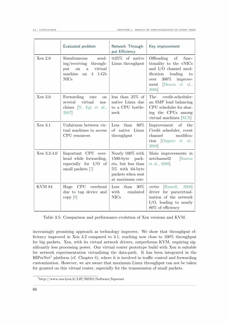
3.5. CONCLUSION CHAPTER 3. IMPACT OF VIRTUALIZATION ON COMM. PERF.
Evaluated problem Network Through-put Efficiency
Key improvement
Xen 2.0 Simultaneous send-ing/receiving through-put on a virtualmachine on 4 1-GbNICs
u25% of nativeLinux throughput
Offloading of func-tionality to the vNICsand I/O channel mod-ification leading toover 300% improve-ment [Menon et al.,2006]
Xen 3.0 Forwarding rate onseveral virtual ma-chines [N. Egi et al.,2007]
less than 25% ofnative Linux dueto a CPU bottle-neck
The credit-scheduler:an SMP load balancingCPU scheduler for shar-ing the CPUs amongvirtual machines [XCS]
Xen 3.1 Unfairness between vir-tual machines to accessCPU resources
Less than 80%of native Linuxthroughput
Improvement of theCredit scheduler, eventchannel modifica-tion [Ongaro et al.,2008]
Xen 3.2-4.0 Important CPU over-head while forwarding,especially for I/O ofsmall packets [7]
Nearly 100% with1500-byte pack-ets, but less than5% with 64-bytepackets when sentat maximum rate
Main improvements innetchannel2 [Santoset al., 2008]
KVM 84 Huge CPU overheaddue to tap device andcopy [9]
Less than 30%with emulatedNICs
virtio [Russell, 2008]driver for paravirtual-ization of the networkI/O, leading to nearly80% of efficiency
Table 3.5: Comparison and performance evolution of Xen versions and KVM.
increasingly promising approach as technology improves. We show that throughput ef-ficiency improved in Xen 3.2 compared to 3.1, reaching now close to 100% throughputfor big packets. Xen, with its virtual network drivers, outperforms KVM, requiring sig-nificantly less processing power. Our virtual router prototype build with Xen is suitablefor network experimentation virtualizing the data-path. It has been integrated in theHIPerNet1 platform (cf. Chapter 6), where it is involved in traffic control and forwardingcustomization. However, we are aware that maximum Linux throughput can not be takenfor granted on this virtual router, especially for the transmission of small packets.
1http://www.ens-lyon.fr/LIP/RESO/Software/hipernet
66

CHAPTER 3. IMPACT OF VIRTUALIZATION ON COMM. PERF. 3.5. CONCLUSION
In addition, for pushing virtualization further inside the network, ensuring good per-formance is crucial, especially as 10 Gb/s links move closer and closer to the edges. Weconclude from the results of this chapter that general purpose OSes and server hardwareare not adapted to high-speed networking. Hence, to bring virtualization to the Internet,it has to be implemented directly in hardware, on special purpose devices; the subject ofthe next chapter.
67

3.5. CONCLUSION CHAPTER 3. IMPACT OF VIRTUALIZATION ON COMM. PERF.
68

4Virtualizing the switching fabric
4.1 Introduction
4.2 Virtualizing the fabric
4.2.1 Controlled sharing
4.2.2 Configurability
4.3 VxSwitch: A virtualized switch
4.3.1 Design goals
4.3.2 Overview of switch architectures
4.3.3 Virtualizing a buffered crossbar
4.3.4 Resource sharing and configurability
4.4 Simulations
4.4.1 Virtual switch simulator
4.4.2 Experiments
4.5 Application
4.5.1 Virtual network context
4.5.2 Use case: Paths splitting
4.5.3 Implementation and simulations using VxSwitch
4.6 Conclusion
The work presented in this chapter has been published at the 11th InternationalConference on High Performance Switching and Routing (HPSR) in 2010 [5]. Inaddition, the work is part of the solutions patented by the LYaTiss company (http:// www. lyatiss. com ) and the Institut National de Recherche en Informatique eten Automatique (INRIA, http: // www. inria. fr/ ) [VxSwitch].
Abstract. For bringing full virtualization to production networks, suchas the Internet, it is necessary to upgrade the current hardware architecturesto cope with high-speed transmissions. The contributions of this chapter are:
Virtua
lization
Sharing
• The design of a virtualized switching fabric, enabling controlledlayer 2 resource sharing and configurability;
• A simulator and the evaluation of VxSwitch, especially on theimpact of resource sharing; and
• Use cases showing how virtualizing the data plane in routersand switches can enable realizing new features in the network.
69

4.1. INTRODUCTION CHAPTER 4. VIRTUALIZING THE SWITCHING FABRIC
4.1 Introduction
Current virtual router implementations allow either high configurability or high perfor-mance, but not both at the same time. Highly configurable virtual routers are those thatvirtualize all their elements, including the data plane, and that allow one to customizethese elements. The prototype we presented in the previous chapter is a high configurablevirtual router, but its current performance makes it unsuitable for production networkssuch as the Internet. High performance virtual routers are those that enable network con-solidation, e.g., Juniper logical routers [Kolon, 2004] [JCS, 2009] or Cisco Nexus [HVR,2008]. In contrast to programmable routers, they enable only standard configuration, andtheir scalability is tightly bound to the hardware, e.g., the number of queues, the numberof forwarding engines. For enabling innovation in the Internet, both, configurability andperformance are required.
Improving the performance of fully configurable, e.g., software routers, is one approachthat has been explored. Parallelization has been suggested as a solution, as it can be real-ized aggregating commodity hardware [Liao et al., 2009] [Dobrescu et al., 2009]. However,such hardware is not designed for packet switching: a limited number of network interfacesis interconnected by a bus, hence bounding the switching performance. Thus, the oppositeapproach is needed for bringing virtualization to the Internet. It consists in adding theconfigurability needed for virtualization to hardware dedicated to switching.
Such configurability requires to share buffers and ports among virtual buffers and vir-tual ports, so that each virtual router can provide configurable and deterministic linkcapacities. Moreover, strong isolation between virtual networks at the data plane levelis ensured. Each virtual router can have customized switching and routing. We pro-pose VxSwitch as a virtualized hardware switch whose switching fabric design allows thecontrolled sharing of the switching hardware [VxSwitch] [5]. VxSwitch enables creating vir-tual switches that are dimensioned in terms of capacity and buffer size, and configurablein terms of layer 2 functionalities. The next section motivates the need for virtualizationat layer 2, and Section 4.3 describes the design of the virtualized switch. VxSwitch isevaluated in Section 4.4 and applications are shown in Section 4.5.
4.2 Virtualizing the fabric
In the previous chapter, we introduced the need for virtualizing the network data plane.In hardware, this means virtualizing the switch ports, buffers and operations such aspacket queueing and scheduling. Besides isolation and scalability, this would introduceinvaluable configurability to the network data plane, while maintaining performance. Byconfigurability at this level, we mean the ability to, 1) dynamically dimension a virtualdevice’s resources, such as port density, port capacity and buffer, and 2) customize itslayer 2 operations, such as packet scheduling and buffer management.
Considering that different operators exploit virtual networks leased on infrastructureprovider’s equipment at a time, as proposed in [Feamster et al., 2007], the switching re-sources could be more efficiently used. If providers would expose routers with a virtualizedswitching fabric, virtual network operators could reserve the exact amount of resourcesthey need, in addition to deploying custom functionality.
70
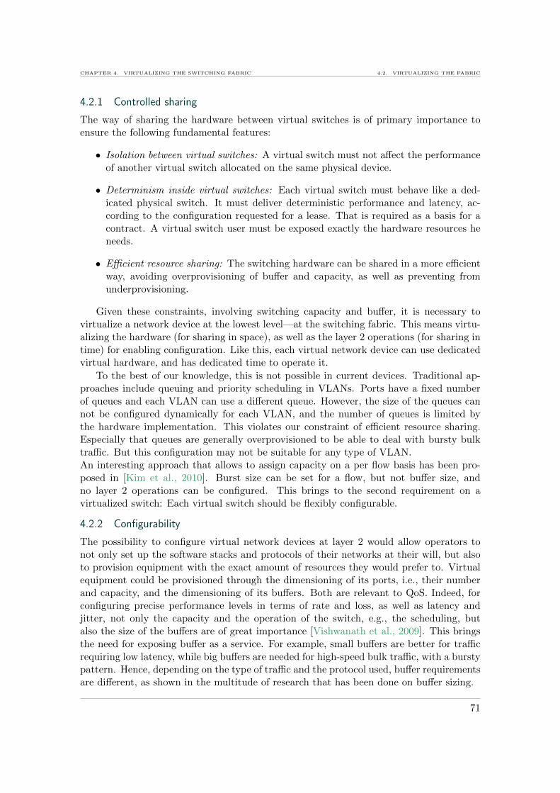
CHAPTER 4. VIRTUALIZING THE SWITCHING FABRIC 4.2. VIRTUALIZING THE FABRIC
4.2.1 Controlled sharing
The way of sharing the hardware between virtual switches is of primary importance toensure the following fundamental features:
• Isolation between virtual switches: A virtual switch must not affect the performanceof another virtual switch allocated on the same physical device.
• Determinism inside virtual switches: Each virtual switch must behave like a ded-icated physical switch. It must deliver deterministic performance and latency, ac-cording to the configuration requested for a lease. That is required as a basis for acontract. A virtual switch user must be exposed exactly the hardware resources heneeds.
• Efficient resource sharing: The switching hardware can be shared in a more efficientway, avoiding overprovisioning of buffer and capacity, as well as preventing fromunderprovisioning.
Given these constraints, involving switching capacity and buffer, it is necessary tovirtualize a network device at the lowest level—at the switching fabric. This means virtu-alizing the hardware (for sharing in space), as well as the layer 2 operations (for sharing intime) for enabling configuration. Like this, each virtual network device can use dedicatedvirtual hardware, and has dedicated time to operate it.
To the best of our knowledge, this is not possible in current devices. Traditional ap-proaches include queuing and priority scheduling in VLANs. Ports have a fixed numberof queues and each VLAN can use a different queue. However, the size of the queues cannot be configured dynamically for each VLAN, and the number of queues is limited bythe hardware implementation. This violates our constraint of efficient resource sharing.Especially that queues are generally overprovisioned to be able to deal with bursty bulktraffic. But this configuration may not be suitable for any type of VLAN.An interesting approach that allows to assign capacity on a per flow basis has been pro-posed in [Kim et al., 2010]. Burst size can be set for a flow, but not buffer size, andno layer 2 operations can be configured. This brings to the second requirement on avirtualized switch: Each virtual switch should be flexibly configurable.
4.2.2 Configurability
The possibility to configure virtual network devices at layer 2 would allow operators tonot only set up the software stacks and protocols of their networks at their will, but alsoto provision equipment with the exact amount of resources they would prefer to. Virtualequipment could be provisioned through the dimensioning of its ports, i.e., their numberand capacity, and the dimensioning of its buffers. Both are relevant to QoS. Indeed, forconfiguring precise performance levels in terms of rate and loss, as well as latency andjitter, not only the capacity and the operation of the switch, e.g., the scheduling, butalso the size of the buffers are of great importance [Vishwanath et al., 2009]. This bringsthe need for exposing buffer as a service. For example, small buffers are better for trafficrequiring low latency, while big buffers are needed for high-speed bulk traffic, with a burstypattern. Hence, depending on the type of traffic and the protocol used, buffer requirementsare different, as shown in the multitude of research that has been done on buffer sizing.
71

4.2. VIRTUALIZING THE FABRIC CHAPTER 4. VIRTUALIZING THE SWITCHING FABRIC
Based on the property that most of the traffic on the Internet is TCP [Lee et al., 2010],the impact of buffer size on TCP flows has been investigated in various work. For example,for TCP flows, packet loss and latency are important caveats to their performance. Forminimizing them, buffer sizing plays an important role, but that depends on multiplecriteria such as the size and the number of flows, besides the transmission rates. In [Prasadet al., 2009], the authors show for example that the ratio between output and inputcapacity of a router determines the relationship between loss probability and buffer size.As another example, there is the well approved rule of sizing buffers to C ×RTT/
√N , as
a derivative of the bandwidth-delay-product, which holds for a large number of flows N ,on a path with a capacity of C and a round-trip time RTT [Appenzeller et al., 2004]. Theimportant revelation from this rule is that the buffer-size dimensioning depends on thenumber of flows multiplexing. Applied to core routers, carrying millions of flows, buffersize can be considerably reduced. However, by the definition of N , sizing queues accordingto this rule is not suitable at the edges, where the routers multiplex much less number offlows. Moreover, it has been shown that the rule does not apply on short-lived TCP flows,hence increasing their packet loss and latency [Tomioka et al., 2007]. Otherwise, buffersizes impact the loss synchronization of TCP flows, as demonstrated in [Hassayoun andRos, 2009]. An experimental study on SLAs, considering latency, loss rate, throughput,jitter, shows that router buffers must be sized differently, depending on the number of flows,their sizes and congestion control algorithms [Sommers et al., 2008]. It has moreover beenconsidered, to adapt buffer sizes dynamically to the minimum value satisfying particularutilization or loss constraints [Zhang and Loguinov, 2008]. Considering the diversity oftraffic and the impact of the buffer size on the performance of each type of traffic, weconclude that different virtual networks that carry different types of traffic should also beable to be configured with different virtual buffer sizes.
A part from resource dimensioning, configurability is also required in the operations ofvirtual switches, so that each can set up a specific QoS. The operations in the switchingfabric consist in packet queuing and scheduling. In order to meet specific latency andrate requirements on a per flow basis, the packet schedulers of a virtual switch need tobe configurable, to set up different policies. A virtual switch forwarding homogeneoustraffic on all ports may for example be configured with a simple round-robin schedulingalgorithm, while a switch transporting different types of traffic may be configured in orderto implement differentiation. Priority scheduling could for example enable a switch toprioritize a specific flow.Moreover, configurability of the queueing mechanisms could enable virtual switches toenqueue packets following different policies. A virtual switch could for example set upalgorithms performing active queue management such as RED (Random Early Detec-tion) [Floyd and Jacobson, 1993], to better control its queue sizes and satisfy specific QoSrequirements.
To introduce such configurability—i.e., resource dimensioning and operationcustomization—to virtual networks, the architecture of router’s and switch’s data planeshave to be upgraded.
72

CHAPTER 4. VIRTUALIZING THE SWITCHING FABRIC 4.3. VXSWITCH: A VIRTUALIZED SWITCH
4.3 VxSwitch: A virtualized switch
In this Section, VxSwitch, the design of a virtualized switch architecture is proposed. Itcan be used for virtualizing the network data plane and building virtual network devicessuch as routers with dedicated virtual hardware and switching functionality.
4.3.1 Design goals
From the possibilities emerging of virtualizing a network device at layer 2 that weredescribed in the previous section, the following design goals have been extracted forVxSwitch:
• Resource dimensioning: A user leasing a virtual switch should be able to specify thenumber of ports, the capacity of each port and the buffer sizes.
• Configurability of functionality: Packet queuing and scheduling algorithms shouldbe configurable on a per virtual switch basis, so that each user can adapt his virtualswitch to the type of traffic it forwards.
• Controlled sharing: A switch must not affect any other in performance. Each switchshould get the exact amount of resources it requires.
These design decisions require to virtualize the architecture of the switch, i.e., itshardware organization, as well as its operations. The first step towards such a new designis to chose an architecture, which is suitable for virtualization.
4.3.2 Overview of switch architectures
Different switch architectures have been proposed over time. In this section, we choose adesign as a basis for a virtualized switch architecture.
4.3.2.1 From bus to crossbar architectures
In the past, switches happened to be built on a shared bus that interconnects inputand output ports. However, this bus being shared by all ports is a bottleneck to switchingpower, as only two ports can communicate at a time. Hence, today, commonly-used switcharchitectures are shared-memory and more recently crossbar [Divakaran et al., 2009].
The shared-memory is known to have scalability issues challenged by the need to ac-cess the memory at a speed equivalent to the product of the line rate and the numberof ports [Iyer and McKeown, 2001]. Overcoming these inhibitions, the crossbar archi-tecture permits N pairs of I/O ports to communicate, with memories running at speedsindependent of the number of ports.
The traditional crossbar switches deploy a centralized, complex matching algorithmto decide which among the contesting ports should communicate. All the selected portstransfer fixed-size packets at the same time, in a synchronous manner. This also requiressegmentation of variable-size packets into fixed-size ‘cells’ at the input, and complementaryreassembly at the output. These constraints are removed with the introduction of buffersat the crosspoints (CP), and leave the choice to perform cell- or packet-scheduling.
73
4.3. VXSWITCH: A VIRTUALIZED SWITCH CHAPTER 4. VIRTUALIZING THE SWITCHING FABRIC
4.3.2.2 Buffered crossbar
On a buffered crossbar, the schedulers are distributed at each output port, and can op-erate independently to switch packets of variable size asynchronously. Having distributedschedulers is an important argument for choosing this architecture for virtualization. Thecomplexity of scheduling algorithms in centralized crossbar architecture (with no bufferingat crosspoints) is usually greater than O(N2) [Tarjan, 1983]. Virtualization of such anarchitecture brings up scalability issues as the number of virtual ports increases. On theother hand, the distributed schedulers in the Crosspoint-Queued (CQ) switch architecturepose no such problem.
Exploiting this technology, a CQ switch [Kanizo et al., 2009] has queues neither atthe inputs nor at the outputs, but only at the crosspoints. Figure 4.1 represents such aCQ switch. Besides, when virtualizing this architecture, its simplicity removes the needto virtualize input/output queues. For more details on CQ switches, we refer the readersto [Kanizo et al., 2009]. Each crosspoint of the switching fabric implements a queue.
Figure 4.1: A Crosspoint-Queued switch.
Incoming packets are sent to the crosspoints according to their destination output port. Ascheduler runs at each output port, selecting packets from one of the different crosspointsconnected to that output. Once a packet is scheduled, it is sent out through the outputline. In the whole process of crossing the switch, the packets go through a single bufferonly.
4.3.3 Virtualizing a buffered crossbar
The resources to be shared in a switch are link capacity (in time) and buffer size (inspace). As said before, each crosspoint of a CQ switch implements a queue. Virtualizingthis architecture into V virtual switches (VSes), each crosspoint buffer used by theseVSes is divided into V virtual buffers, each one implementing a virtual queue. If bi,jis the physical queue size at crosspoint (i, j), it is shared among the VSes, with eachVSk, k ∈ [1, V ] owning bki,j of the queue at crosspoint (i, j). We refer to the virtual buffersas ‘virtual crosspoint buffers’ (VXBs). Table 4.1 lists some of the commonly used notationsin this chapter.
The sharing of input/output ports is similar. That is, the link capacity of a physical
74

CHAPTER 4. VIRTUALIZING THE SWITCHING FABRIC 4.3. VXSWITCH: A VIRTUALIZED SWITCH
Notation Description
1 ≤ Nk ≤ N Number of ports of VSk
Ck(in) = [cki (in)], i = 1 . . . Nk Capacity vector for input ports of VSk
Ck(out) = [cki (out)], i = 1 . . . Nk Capacity vector for output ports of VSk
Fk = [fki,j ]Nk×Nk Matrix of forwarding paths of VSk
Bk = [bki,j ]Nk×Nk Matrix of CP buffer sizes of VSk
Qk = [qki,j ]Nk×Nk Matrix of queue managers of VSk
Sk = [ski ], i = 1 . . . Nk Output scheduler vector for output ports of VSk
Lk = [lki ], i = 1 . . . Nk Lookup vector for input ports of VSk
τk Lifetime of VSk
Table 4.1: Table of notations
port is shared among different VSes. Virtualizing ports gives rise to ‘virtual ports’, eachreceiving a part of the capacity of the physical port.Virtual ports are dimensioned by user-defined input and output rates cki (in) and cki (out)for each port i. Moreover, as opposed to classical switches, in a VxSwitch, all inputs maynot be connected to all outputs. As an example, a switch interconnecting a server withseveral clients may not want to provide connectivity between clients. To take this intoaccount, forwarding paths are explicitly represented by a matrix Fk. If there are V VSesall requiring a share of port i, then each virtual port of VSk has a different capacity cki .This sharing is performed by a scheduler whose service discipline is adjusted to satisfy thecriteria of all VSes owners while optimizing the productivity of the physical host-switch.Details on scheduling are given in Section 4.3.4.1.
While combining different VSes on the same physical switch, the allocation of anyVSk has to satisfy respectively conditions 4.1 and 4.2 for each of its ports and each of itsbuffers:
cki ≤ ci −V∑
x=1,x 6=k
cxi ,∀i ∈ [1, N ] (4.1)
bki,j ≤ bi,j −V∑
x=1,x 6=k
bxi,j , ∀i,∀j ∈ [1, N ] (4.2)
These constraints guarantee isolation, ensuring that each VS sharing the VxSwitchobtains the required amount of resources and predictable performance, and that VSes donot affect each others performance.
For functional customization, users can also configure the lookup mechanisms, Lk atthe input ports, just like the schedulers Sk at the output ports and the queue managersQMk at the crosspoints. Thus, each VS has control over the packets, once they enterthe switch. This exposes dedicated lookup to upper-layer virtual routers, each of whichmay run a different protocol. Such a flexible lookup module can be implemented usingfor example a modular architecture like PLUG [De Carli et al., 2009]. A lifetime τk isassociated with each VS.
75

4.3. VXSWITCH: A VIRTUALIZED SWITCH CHAPTER 4. VIRTUALIZING THE SWITCHING FABRIC
S1 S2
L1
L2
QM1,1 QM1,2
QM2,1 QM2,2
mem
host VS 1 VS 2
Scheduler per output port
S1VXB
S2VXB
VL11 VL2
1
VL12 VL2
2
SV S
mem
host VS 1 VS 2
VQM 1
VQM 2
QM1,1
Virtual Queue Manager
VXB11,2
VXB12,2VXB1
2,1
VXB21,2
VXB22,1 VXB2
2,2
VXB11,1
VXB21,1
Figure 4.2: Architecture of VxSwitch’s virtualized switching fabric.
Figure 4.2 depicts a VxSwitch based on a virtualized CQ architecture. In this simplifiedexample, the switch hosts two VSes, each one using all the physical ports. Incoming packetsare demultiplexed to the corresponding VS after a lookup action. This classification candepend on header fields, for example, the IP source/destination addresses, VLAN tag, ToS,or an additional shim header like in MPLS. One could also imagine using a controller suchas OpenFlow [McKeown et al., 2008] to dynamically change and identify virtual networks.After the lookup, a packet is sent to the corresponding VXB if it has enough space left.Scheduling takes place at each output port. A scheduler per physical output port choosesamong the virtual switches at each time-slot, then another scheduler, inside the chosenVS and the output port, selects a VXB to be dequeued.
The mechanism of classification and queuing to different virtual buffers is derived fromQoS management in routers, where flows are grouped into service classes and memory ispartitioned into logical queues. While, in classical QoS implementations, shaping andpolicing are usually performed on an output port with a set of virtual buffers, the virtu-alized crosspoint-queue switch implements shaping in a decentralized manner schedulingseveral crosspoint queues per output port.
VNet Id
Lookup VS specific
lookupDequeue
input outputVXB
Enqueue at
Figure 4.3: Successive actions performed on a packet traveling throughout VxSwitch.
Figure 4.3 depicts the different operations a packet undergoes while traveling through-out a VxSwitch. It enters the line card, where a two-level lookup is performed. The firstlookup figures out to which virtual network (VNet), and thus VS, the packet belongs.
76
CHAPTER 4. VIRTUALIZING THE SWITCHING FABRIC 4.3. VXSWITCH: A VIRTUALIZED SWITCH
The second lookup is specific to the VS. According to the result, the linecard sends thepacket to the selected VXB, from where it is dequeued once it is at the head and has beenselected by a scheduler.
4.3.4 Resource sharing and configurability
The resources of the virtualized switch are shared in time and space. Sharing in timeis assured by scheduling algorithms determining at which moment each virtual buffer isdequeued. Sharing in space takes place in the buffers which are split into multiple virtualqueues. Each crosspoint buffer is shared into VXBs, one per VS using this crosspoint. Im-plementing queue management and packet scheduling on the crossbar requires additionalmemory, but this should not be the bottleneck, especially with the increasing density ofVSLI. It is rather the number of pins, whose number is constrained, which makes virtual-ization of a crossbar even more appealing [Mhamdi et al., 2006].
4.3.4.1 Virtualized scheduling
In the example of Figure 4.2, the virtualized switch has two input ports and two outputports, and four crosspoints, used by two VSes. Incoming packets at each port are classifiedby the responsible queue manager (QM) to the corresponding VXB. For a given outputport i, a scheduler (Si) decides from which crosspoint and from which VXB the nextpacket will be dequeued. For isolation and customization of VS scheduling, there are twolevels of scheduling. An Inter-VS scheduler selects among the VSes, which one to select.It is responsible of performance isolation between the different VSes. In addition, eachVS has an Intra-VS scheduler, which selects the VXB from which to dequeue. Both, theinter- and the intra-VS schedulers can operate using different policies. The choice of thepolicy will depend on the type of each hosted VS, and on the switch maintainer’s interestin maximizing the utilization.
As an example, a switch provider hosting several VSes, each one switching bulk trafficthat needs high throughput, and having no strict constraints on delay and burstiness, canuse a variable sharing policy. This means, it allows VSes to temporarily exceed their band-width, and risks in turn to get smaller bandwidth at another moment while other VSesexceed their bandwidth. For the switch providers, this brings the advantage of maximizingtheir equipment use, and for the VS operators, of not paying for peak rate guarantees ifit is not strictly required for them.In another scenario, one of the hosted VSes might have delay-sensitive traffic and requirestrict minimum bandwidth guarantees. Hosting such a VS would imply for the VxSwitchto use another intra-VS scheduling model in order to satisfy the VS’s delay constraintsand avoid impact from other VSes on the capacity.Inside a VS, an operator can also choose different strategies, e.g., Round-Robin (RR),Longest Queue First (LQF), or First Come, First Served (FCFS), depending on the re-quirements in terms of delay, jitter, buffer-size, or scheduling complexity. In an operationalnetwork, the choice of the scheduling and sharing strategies comes with a business andpricing model which are not developed here. It focuses primarily on the architectureallowing this flexibility in scheduling.
The internal architecture of this two-level scheduling module within the crossbar isshown in Figure 4.2 for scheduler S2. The inter-VS scheduler SVS shares capacity betweenthe different VSes. At each scheduling decision, it selects which VS is scheduled and for
77
4.4. SIMULATIONS CHAPTER 4. VIRTUALIZING THE SWITCHING FABRIC
how long, or for how many packets or bytes. Each VS has an internal VXB schedulingmodule Sk
VXB responsible for this, which is called by the inter-VS scheduler. Inter-VS andintra-VS schedulers logically share the scheduler’s memory to register state information.This requires V times more memory for the scheduler, when the switch hosts V VSes.When a VS is scheduled, it acts like a physical switch, but chooses only from its ownVXBs, and dequeues only during the time period it has been attributed. Each VS havingat maximum V VXBs, each intra-VS scheduler has a complexity of O(V ). As only oneintra-VS scheduler operates at a time, the overall scheduling complexity is also of O(V ).
4.3.4.2 Virtualized buffer management
While scheduling aims at guaranteeing a specific rate for the ‘virtual link’, the ‘virtualbuffer’ size is defined by the different possible buffer-sharing policies.
The possibility to change memory and queue sizes on crossbars [Mhamdi et al., 2006]enables VXBs to be flexibly dimensioned. Each such VXB is accessible only by packetsof the VS to which it belongs. Moreover, a virtual queue manager (VQM) for each VXBcan be configured, to perform specific queue management, deciding on where to enqueuea packet and from where to drop a packet, or performing active queue management. Acrosspoint queue manager (QM), selects for an incoming packet which VQM is responsiblefor enqueuing it. Its internal architecture is shown in Figure 4.2 for QM 1,2.
The physical crosspoint queue can be shared among different VSes in a strict way orin a flexible way. If the sharing is strict, the VXBs have each a fixed size. Such a settingmay lead to an inefficient use of buffers, as packets belonging to a VS are dropped whenthe corresponding VXB is full, even though there is space for it in the physical crosspointqueue.
This is where another mode of buffer sharing is helpful. In the flexible buffer sharingpolicy, a VXB can be resized provided that the other VXBs sharing the crosspoint allowsuch resizing. For example, for increasing a VXB of n Bytes, there must be n Bytes offree space in the concurrent VXBs. Such a dynamic buffer sharing reduces the numberof losses (compared to the strict buffer-sharing policy). This allows a number of dynamicbuffer-sharing policies—every VSk can decide to set aside a fraction of its queue size, sayF ki,j , that can be attributed to other VSes that share the crosspoint (i, j). The order in
which packets are dequeued can also be an interesting decision criteria. A VS operatorwould like to give priority to its packets before dequeuing F k
i,j .
4.4 Simulations
For evaluating the described virtualized switch architecture and its scheduling paradigms,we developed a simulator that runs multiple VSes in parallel, simulating the sharing ofcommon physical resources. It is used to evaluated the performance of VxSwitch, andexplore the individual configurability of virtual switches.
Virtualization, and hence the sharing of the resources such as buffer and capacity,introduce new challenges to a switch. For example, several small buffers may acceptless packets than one big buffer. In addition, scheduling needs to take into account andensure the capacities of each of the virtual switches, while enabling each virtual switch toexecute its own scheduling algorithm. This simulation sheds light into these issues andthe resulting performance impact, compared to a non virtualized buffered crossbar.
78
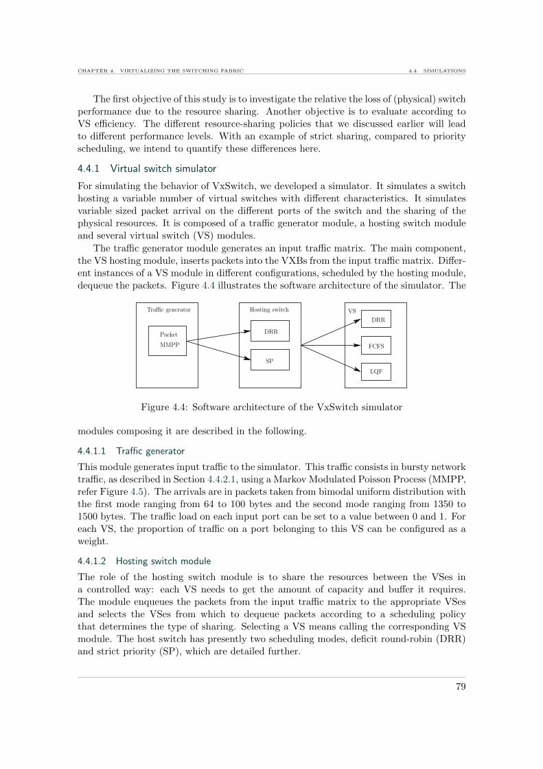
CHAPTER 4. VIRTUALIZING THE SWITCHING FABRIC 4.4. SIMULATIONS
The first objective of this study is to investigate the relative the loss of (physical) switchperformance due to the resource sharing. Another objective is to evaluate according toVS efficiency. The different resource-sharing policies that we discussed earlier will leadto different performance levels. With an example of strict sharing, compared to priorityscheduling, we intend to quantify these differences here.
4.4.1 Virtual switch simulator
For simulating the behavior of VxSwitch, we developed a simulator. It simulates a switchhosting a variable number of virtual switches with different characteristics. It simulatesvariable sized packet arrival on the different ports of the switch and the sharing of thephysical resources. It is composed of a traffic generator module, a hosting switch moduleand several virtual switch (VS) modules.
The traffic generator module generates an input traffic matrix. The main component,the VS hosting module, inserts packets into the VXBs from the input traffic matrix. Differ-ent instances of a VS module in different configurations, scheduled by the hosting module,dequeue the packets. Figure 4.4 illustrates the software architecture of the simulator. The
Traffic generator
Packet
MMPP
Hosting switch
DRR
SP
VS
DRR
FCFS
LQF
Figure 4.4: Software architecture of the VxSwitch simulator
modules composing it are described in the following.
4.4.1.1 Traffic generator
This module generates input traffic to the simulator. This traffic consists in bursty networktraffic, as described in Section 4.4.2.1, using a Markov Modulated Poisson Process (MMPP,refer Figure 4.5). The arrivals are in packets taken from bimodal uniform distribution withthe first mode ranging from 64 to 100 bytes and the second mode ranging from 1350 to1500 bytes. The traffic load on each input port can be set to a value between 0 and 1. Foreach VS, the proportion of traffic on a port belonging to this VS can be configured as aweight.
4.4.1.2 Hosting switch module
The role of the hosting switch module is to share the resources between the VSes ina controlled way: each VS needs to get the amount of capacity and buffer it requires.The module enqueues the packets from the input traffic matrix to the appropriate VSesand selects the VSes from which to dequeue packets according to a scheduling policythat determines the type of sharing. Selecting a VS means calling the corresponding VSmodule. The host switch has presently two scheduling modes, deficit round-robin (DRR)and strict priority (SP), which are detailed further.
79
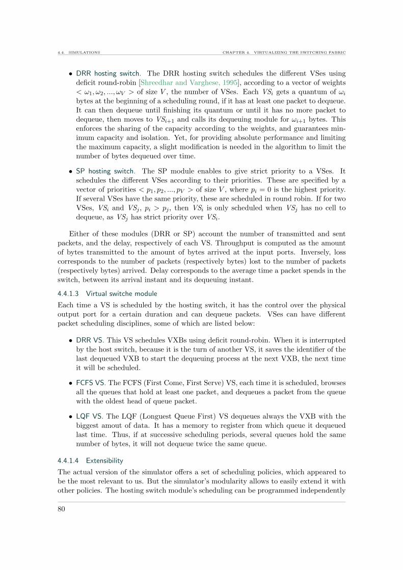
4.4. SIMULATIONS CHAPTER 4. VIRTUALIZING THE SWITCHING FABRIC
• DRR hosting switch. The DRR hosting switch schedules the different VSes usingdeficit round-robin [Shreedhar and Varghese, 1995], according to a vector of weights< ω1, ω2, ..., ωV > of size V , the number of VSes. Each VSi gets a quantum of ωi
bytes at the beginning of a scheduling round, if it has at least one packet to dequeue.It can then dequeue until finishing its quantum or until it has no more packet todequeue, then moves to VSi+1 and calls its dequeuing module for ωi+1 bytes. Thisenforces the sharing of the capacity according to the weights, and guarantees min-imum capacity and isolation. Yet, for providing absolute performance and limitingthe maximum capacity, a slight modification is needed in the algorithm to limit thenumber of bytes dequeued over time.
• SP hosting switch. The SP module enables to give strict priority to a VSes. Itschedules the different VSes according to their priorities. These are specified by avector of priorities < p1, p2, ..., pV > of size V , where pi = 0 is the highest priority.If several VSes have the same priority, these are scheduled in round robin. If for twoVSes, VSi and VSj , pi > pj , then VSi is only scheduled when VSj has no cell todequeue, as VSj has strict priority over VSi.
Either of these modules (DRR or SP) account the number of transmitted and sentpackets, and the delay, respectively of each VS. Throughput is computed as the amountof bytes transmitted to the amount of bytes arrived at the input ports. Inversely, losscorresponds to the number of packets (respectively bytes) lost to the number of packets(respectively bytes) arrived. Delay corresponds to the average time a packet spends in theswitch, between its arrival instant and its dequeuing instant.
4.4.1.3 Virtual switche module
Each time a VS is scheduled by the hosting switch, it has the control over the physicaloutput port for a certain duration and can dequeue packets. VSes can have differentpacket scheduling disciplines, some of which are listed below:
• DRR VS. This VS schedules VXBs using deficit round-robin. When it is interruptedby the host switch, because it is the turn of another VS, it saves the identifier of thelast dequeued VXB to start the dequeuing process at the next VXB, the next timeit will be scheduled.
• FCFS VS. The FCFS (First Come, First Serve) VS, each time it is scheduled, browsesall the queues that hold at least one packet, and dequeues a packet from the queuewith the oldest head of queue packet.
• LQF VS. The LQF (Longuest Queue First) VS dequeues always the VXB with thebiggest amout of data. It has a memory to register from which queue it dequeuedlast time. Thus, if at successive scheduling periods, several queues hold the samenumber of bytes, it will not dequeue twice the same queue.
4.4.1.4 Extensibility
The actual version of the simulator offers a set of scheduling policies, which appeared tobe the most relevant to us. But the simulator’s modularity allows to easily extend it withother policies. The hosting switch module’s scheduling can be programmed independently
80

CHAPTER 4. VIRTUALIZING THE SWITCHING FABRIC 4.4. SIMULATIONS
of the VSes, and new scheduling policies can easily be programmed independently of theVS modules. Moreover, a different module exists for each VS type (in terms of scheduling).Thus, the simulator can easily be extended with new VS types by adding new VS modules.Any of the VS modules can be combined to simulate a switch hosting different types ofVSes simultaneously and observe the performance due to traffic arrival and scheduling. Inthe same way, other input traffic generator modules can be added to the simulator.
4.4.2 Experiments
This section gives simulation results on the overall performance of a virtualized switch interms of throughput, as well as the individual VS performance, in case of heterogeneousVSes sharing the same VxSwitch. The different simulations have two main goals:
• Determine the consequence of sharing switching resources into fixed sized virtualresources, instead of sharing them in an uncontrolled way between all traffic in aphysical switch;
• Experiment with the configurability of VxSwitch and show how customized sched-uler and buffer configurations can satisfy individual requirements of different virtualswitches, inside a single VxSwitch.
4.4.2.1 Metrics
The metrics we consider are throughput, loss, and delay. The throughput of a switch isdefined as the percentage of arrived packets that departed the switch. In a virtualizedswitch, to calculate the total throughput, we use the sum of the arrived packets whichwere admitted in any of the VSes. The loss rate is complementary to the throughput,being the percentage of arrived packets which are dropped due to queue overflow. Thedelay is the time spent by a packet in the switch. The scalability of the virtualized switchis analyzed by varying the number of VSes it hosts for different buffer sizes.
The generated input traffic emulates bursty network traffic. A Markov ModulatedPoisson Process (MMPP, refer Figure 4.5) is used for the arrival process. The arrivalsare in packets, with sizes taken from bimodal uniform distribution, where the first modevaried from 64 to 100 bytes and the second mode varied from 1350 to 1500 bytes.
21
λ1 λ2
ω1
ω2
Figure 4.5: MMPP model: λ1 and λ2 are the arrival rates; ω1 and ω2 are the transitionrates
The simulations are executed using the described input traffic scenario. Each experi-ment is run tun times. The average values are presented. The physical crosspoint buffer(CB) sizes vary as multiples of 1500 bytes, since it is the minimum size necessary to holdone maximum-size packet. The simulated physical switch has N = 32 ports. The input
81

4.4. SIMULATIONS CHAPTER 4. VIRTUALIZING THE SWITCHING FABRIC
traffic is generated at each physical input port with a load of ρ = 1/N , in order to chargethe output port by a load of 1. It is then split into the different VSes according to weights.Similarly, we assume that the traffic at each input port is uniformly distributed to theoutput ports. Thus, for simplicity, we explain the details with respect to a single outputport.
4.4.2.2 VxSwitch overall performance
The first experiment evaluates a virtualized switch hosting homogeneous VSes (they allhave the same VXB size and the same virtual port capacities). Input traffic for each VSarrives with a load of 1/(N ∗ V ) on each port, where N is the number of ports and V thenumber of VSes, to have a total load of 1 on the output port. VSes are served using a deficitround-robin (DRR) [Shreedhar and Varghese, 1995] scheduler to ensure the fair sharingof output link rate, serving each VS during at least 1/V of a scheduling round, as long asit has packets to dequeue. All the VSes have the same quantum q = 1500. Each VS has adeficit counter (DC), which gets increased by one quantum each time it is scheduled andhas packets to dequeue. It is allowed to dequeue at maximum DC unities of data beforethe next VS gets scheduled. This small quantum size, allowing to dequeue only a single1500-byte packet, minimizes rate variation and delay in the VSes and maximizes isolationbetween them. Inside each VS, a separate instance of DRR is used to dequeue packets ina fair way from the different VXBs. The quantum of each VXB is also chosen equal to1500 bytes. Note that, independently of the host switch’s VS scheduling, a VS could alsouse another VXB scheduling algorithm like FCFS, LQF, etc. But for homogeneity, eachVS here uses the same algorithm with the same parameters.
In the different runs, the number of VSes as well as the size of the crosspoint buffers(CBs) are varied to evaluate the scalability of the switch, and the impact of buffer size onthe performance. Figure 4.6 shows the throughput of the virtualized switch hosting 2 to32 VSes and having crosspoint buffer sizes between 3 and 192 kB. The result numbered ‘1’on the x axis corresponds to the performance of the physical switch. Per VS throughputis not represented here, as it is equivalent to the total throughput of all VSes. Meandeviation is of negligible significance in these results.
In this configuration, with up to 32 VSes, the total throughput of the physical switchis always above 90%, given a VXB size (CB/V ) of at least 1500 bytes. The throughputis highly dependent on the CB size. By segmenting the buffers into fixed-size VXBs, theusable buffer capacity shrinks by a fraction, and this inefficiency increases with the numberof VXBs. Thus, enabling the hosting of several VSes with isolated VXBs requires the hostswitch to scale in buffer size, at least to give each VXB the size of one maximum sizepacket. A CB size of 96 KB allows over 99% throughput for up to 32 VSes. For a crossbarwith 32 1 Gb/s-ports, this would require a total of about 100 MB of buffer.
Figure 4.7 shows the average delay per VS on one VxSwitch, for different numbers ofVSes sharing the VxSwitch, and different VXB sizes. When the buffers are too small, i.e.,the configurations where the throughput is significantly below 100% (see correspondingresults in Figure 4.6), the delay increases with an increasing number of VSes. Indeed, if allVS’s VXBs are full, a VS needs to wait longer for its turn to come with DRR schedulingand its packets experience more delay.When the buffers are big enough, or bigger than necessary (the cases where close to 0%packet loss occurs), delay does not increase with the number of VSes. This is for example
82

CHAPTER 4. VIRTUALIZING THE SWITCHING FABRIC 4.4. SIMULATIONS
92
93
94
95
96
97
98
99
100
1 2 4 8 16 32
Thro
ughput
(%)
Number of VSes (log scale)
CB: 3 kBCB: 6 kB
CB: 12 kBCB: 24 kBCB: 48 kBCB: 96 kB
CB: 192 kB
Figure 4.6: Throughput of a VxSwitch with different CB sizes, hosting different numbersof VSes.
0.0
0.2
0.4
0.6
0.8
1.0
1.2
1.4
1 2 4 8 16 32
Del
ay (
ms)
Number of VSes (log scale)
VXB: 1.5 kBVXB: 3 kBVXB: 6 kB
VXB: 12 kBVXB: 24 kBVXB: 48 kB
CB: 3 kBCB: 6 kB
CB: 12 kBCB: 24 kBCB: 48 kBCB: 96 kB
CB: 192 kB
Figure 4.7: Delay on a VxSwitche with different VXB sizes.
the case for a VXB size of 48 kB, where increasing from 2 to 4 VSes does not increasethe delay. This is probably related to the fact that each of the 4 VXBs at each crosspointcontains on average only half of the number of packets than each of the 2 VXB in the caseof 2 VSes, as rate is divided by two.
83

4.4. SIMULATIONS CHAPTER 4. VIRTUALIZING THE SWITCHING FABRIC
In conclusion, with this type of bursty packet traffic, sharing a buffer impacts on theperformance as more losses occur. On the other hand, delay increases naturally with thenumber of VSes, as one VS must wait for others to complete their jobs. In this example,delay increases only when packet loss occurs, i.e., the buffers are not big enough. But ingeneral, buffer size, and hence delay will depend on the type of traffic, the burst sizes, andthe rate.
In general, inefficiency in sharing can be decreased by using variable buffer sharing,and also by more traffic-aware scheduling. In this example of homogeneous sharing, VSesare served in a fixed order. Hence, a VS might be scheduled at a moment where it has fewpackets to dequeue, thus blocking other virtual switches with full queues. This might beparticularly penalizing for ’small’ VSes using only a small part of the resources and beingscheduled after very big intervals, thus suffering from high delays in round-robin.
4.4.2.3 Sharing resources differently
In this section, the advantages of configurability are evaluated. A VxSwitch is shareddifferently, by two VSes where each has other performance requirements. The experimentsshow how the adaptation of the scheduling of the VSes can improve the performance ofeach of them. VS1 requires little bandwidth—10% of the available capacity—on each port,and minimal delay. VS2 needs high bandwidth—90% of the available capacity—on eachport, and has no constraints on delay. In this scenario, DRR scheduling like before wouldcause high delays to VS1, giving it only one quantum in 10, to dequeue a packet. As analternative, strict-priority (SP) scheduling is implemented in the physical switch, alwaysgiving VS1 priority over VS2. Hence, VS1 can dequeue packets when they arrive, thusmomentarily exceeding the 10% of reserved average rate. The resulting variable-sharingscheduling policy is compared to the previous fair sharing with DRR. Inside each VS, thesame scheduler (DRR) is used, to focus only on the impact brought by different inter-VSscheduling strategies.
In both cases, the throughput and delay are evaluated as a function of different allo-cations of 15-kB CBs among the two VXBs. Figures 4.8 and 4.9 show, respectively, theaverage throughput and the delay obtained on each VS, in the ten runs. Giving priorityto VS1 increases the loss on VS2 by less than 1%, compared to DRR, while throughput ofVS1 is highly increased. It reaches 100% for a VXB size starting from 3 kB, while withDRR, VS1 obtains 99% of throughput starting only from a buffer size of 6 kB, due toincreased latency, as VS1 is scheduled only once in 10 times.
Regarding throughput, giving priority to a low-bandwidth VS improves, on the average,the individual throughput of both VSes, even if the total physical switch throughputdecreases very slightly (by less than 1%). Regarding the delay, the improvement usingSP is even more important. Figure 4.9 shows that VS1, using SP scheduling, decreasesits delay by 0.1 to nearly 0.6 ms. Meanwhile, the delay of VS2 is increased by less then0.2 ms in the worst case of having only a 1500-bytes VXB. Also, standard deviation isdepicted in both scheduling scenarios. Giving VS1 priority over VS2 allows it to achievean almost constant delay with very slight variation, while with DRR, it varies by upto 0.15 ms around the average. The delay deviation of VS2 is negligible and similar inboth scenarios, varying around less then 0.05 ms. For VS-operators, in this configuration,priority scheduling sounds to be the better solution, at the cost of a very small decreasein the overall throughput.
84

CHAPTER 4. VIRTUALIZING THE SWITCHING FABRIC 4.4. SIMULATIONS
86
88
90
92
94
96
98
100
(1.5/13.5)
(3.0/12.0)
(4.5/10.5)
(6.0/9.0)
(7.5/7.5)
(9.0/6.0)
(10.5/4.5)
(12.0/3.0)
(13.5/1.5)
Thro
ughput
(%)
VXB size (VS1/VS
2) (kB)
Prio VS1
Prio VS2
DRR VS1
DRR VS2
Figure 4.8: Throughput of a VxSwitch hosting two VSes, using respectively 10% and 90%of the capacity.
0.0
0.1
0.2
0.3
0.4
0.5
0.6
0.7
0.8
0.9
1.0
(1.5/13.5)
(3.0/12.0)
(4.5/10.5)
(6.0/9.0)
(7.5/7.5)
(9.0/6.0)
(10.5/4.5)
(12.0/3.0)
Del
ay (
ms)
VXB size (VS1/VS
2) (kB)
DRR VS1
DRR VS2
Prio VS1
Prio VS2
Figure 4.9: Delay of two VSes hosted on a VxSwitch and using respectively 10% and 90%of the capacity.
These experiments give an insight on the variation of VS performance, depending onthe type of resource sharing that is employed. Further investigation on this virtualizedarchitecture is necessary to choose the best sharing strategies.
85

4.5. APPLICATION CHAPTER 4. VIRTUALIZING THE SWITCHING FABRIC
4.5 Application
The flexibility introduced to the network by the ability to flexibly dimension and configurevirtual routers and switches brings new use cases and allows to implement features thatremained concepts until now. In this section, we show a particular application of VxSwitchenabling transparent virtual path-splitting.
4.5.1 Virtual network context
Virtualization has been proposed to decouple virtual network operators from networkinfrastructure providers [Feamster et al., 2007]. In such an application, virtual serviceoperators can exploit virtual networks and configure them independently from each other.For realizing this, we imagine that the different virtual networks are hosted on a physicalnetwork infrastructure or federation of infrastructures, and are managed through a man-agement plane, like suggested, e.g., in [Greenberg et al., 2005]. Figure 4.10 illustrates sucha scenario. The management plane exposes the configuration facility to administrators
VxSwitch
VxSwitch
VxSwitch
VxSwitch
Prioritize vPort on VSDelete VS
Add vPort to VS
VS VS VS
VS VS
VS VS
VS VS
Network management plane
Create, add VS, pause, etc.
Create VS
Migrate, reconfigure scheduler, add port, etc.
Figure 4.10: Management of a network of VxSwitches.
to deploy, reconfigure, save or release virtual networks. When an administrator issues avirtual-network configuration request to the network-management plane, the latter trans-lates it into operations to execute on the different VSes. The management plane can alsodecide by itself to reconfigure a virtual network, transparently to the users, e.g., migrate arunning VS for load balancing. Thanks to layer 2 virtualization in VxSwitches and the re-sulting isolation and customization flexibility of VSes, virtual networks can be configuredthrough elementary operations on VSes such as adding or deleting virtual ports, recon-figuring their capacities, adding or deleting buffers and reconfiguring their size, as well aschoosing scheduling and lookup mechanisms at any time. The synchronized execution ofsuch operations on the different VSes composing a virtual network can result in precisevirtual-network configuration, fitting to specific use cases, some of which are describedbelow.
86
CHAPTER 4. VIRTUALIZING THE SWITCHING FABRIC 4.5. APPLICATION
4.5.2 Use case: Paths splitting
A new problem that arose with network virtualization consists in how to map virtualnetworks on a physical substrate, satisfying all constraints such as processing and memoryrequirements in nodes and bandwidth on links. One interesting solution has been proposed,that decomposes virtual links, and allocates them on parallel physical paths, to overcomethe hardware limitations in terms of capacity [Yu et al., 2008]. The practical issue of thissolution is that such a decomposed virtual link may deliver packets in disorder, due todifferent latencies on the different physical paths. This problem is mostly solved at thetransport layer, e.g., using multi-path TCP, a version of TCP that is designed to dealwith transporting data over several parallel paths [Barre et al., 2010] [Ford et al., 2011].In the context of virtual networks, path splitting has also been proposed as transportvirtualization (TV) [Zinner et al., 2010]. In the following, we show how the configurabilityof VxSwitch can remedy these issues.
4.5.2.1 Concept
Figure 4.11 illustrates the concept of virtual path splitting, representing a virtual link,we call VLink, allocated on two parallel physical paths. VLink represents the virtual link
VLink
Virtual Network Provider
Substrate
Virtual Network Operator
Physical Switch
VxNode 2
VxLinkVxLink
VxNode 3VxNode 1
Figure 4.11: Layers of virtualization required to efficiently provide a virtual link on topof a physical substrate. VLink is split between two physical paths. The network providerconfigures a set of VxLinks and VxNodes to implement the VLink splitting and to providethe QoS requirements.
seen from the perspective of virtual network operator. They are not aware of the physicalallocation, and instead, see the virtual link like if it was a physical link, configured with anSLA, specifying for example guaranteed capacity and latency. The bottom layer representsthe physical network where the VLink is mapped to. The intermediate layer representsthe network as it is seen by the virtual network provider, who is in charge of supplyingthe VLink with the requested SLA to the virtual network operator. It is composed ofpartitions of all physical resources involved in the implementation of the VLink. We referto these resource partitions as VxLinks (partitions of physical links) and VxNodes (virtualrouters or switches). In this example, the VLink is split over two physical paths, allocatedbetween the VxNodes 1 and 3. In order to fulfill the SLA requested by the virtual networkoperator on the VLink, VxLinks have to be provisioned with specific bandwidth, whileVxNodes have to be provisioned with specific buffer sizes and scheduling algorithms.
87

4.5. APPLICATION CHAPTER 4. VIRTUALIZING THE SWITCHING FABRIC
Such a virtual link embedding solution may lead to performance drawbacks, due tothe possible disorder of packets, and difference of latency on the parallel physical paths.This will have an important impact, especially on TCP flows that are sensitive to loss andlatency. That is, where VxSwitch can come as a solution, to configure the switching planeof the different VxNodes underneath the VLink, in order to deal with packet disorder. Infact, it allows to flexibly configure buffer sizes, one main aspect to performance and torecover from packet disorder. The following section describes the possible configurationand illustrates it with simulations.
4.5.3 Implementation and simulations using VxSwitch
In this section, we use the simulator to implement the previously described use case andplay with the configurability of VxSwitches, to see how they can realize a split virtual linkallocation, depending on the physical network.
4.5.3.1 Simulation setup
Two VxSwitches, 1 and 2, were created using the simulator, each hosting one VS, respec-tively VS1 and VS2, as represented in Figure 4.12. Each VxSwitch x has two input ports,px,1 and px,2, and two output ports px,3 and px,4. They are interconnected by two physicalpaths, L1 and L2. VS1 and VS2 are interconnected over a virtual link that is split over
S
D
VxSwitch 1VxSwitch 2
P 1,3 P 1,4
L1
L2P 1,2
P 2,1
P 2,2
P 2,3 P 2,4
P 1,1
VXB 2VXB 1VXB 3
VXB 4
VS2
VS1
Figure 4.12: Simulation architecture: Two VSes (represented in red), allocated on twoVxSwitches, interconnected over two paths over a physical network.
the two physical paths, L1 and L2, allocating half of the capacity of each. The traffic oninput port p1,1 of VS1 is equally split by the classifier S to the two output ports, p1,3 andp1,4. For assuring this task, we added a classifier module to the VxSwitch simulator. Thismodule, besides splitting the traffic, assignes a sequence number to each packet. On VS2,the traffic of the two paths, L1 and L2 is re-aggregated by the output scheduler D on portp2,3.
Each VS has two dedicated VXBs, at the interconnection points of their input andoutput ports. The output schedulers of VxSwitch 1 are configured with Deficit RoundRobin (DRR), attributing 50% of the processing on each output port to each, VS1 andthe cross-traffic, for dequeuing packets. The output scheduler D of VS2 on p2,3 is configuredso as to dequeue packets according to their order of arrival at VS1, to hide the impact ofsplitting. For this, we implemented an additional sub-module in the hosting switch moduleof the simulator that dequeues packets sequentially according to their sequence numbers.
88

CHAPTER 4. VIRTUALIZING THE SWITCHING FABRIC 4.5. APPLICATION
Capacities are allocated for the VSes as follows: they use 100% of the capacity on inputp1,1 and output p2,3, and 50% of each of the two paths L1 and L2. The other resources ofthe two VxSwitches are used by cross traffic in order to use 100% of its physical capacity.
The simulator operates on variable-size packets. The input traffic was generated witha Markov Modulated Poisson arrival process, and packet sizes were taken from a bimodaluniform distribution, where one mode varied from 64 to 100 bytes, the other from 1350 to1500 bytes, like for the previous simulations. The input rate at each port is of 1 Gb/s.
Sizing VXBs to absorb VS internal latency differences. In the first simulation, we considerpaths L1 and L2 having the same latency. Hence packet reordering at D in VS2 may berequired only due to disorder introduced by VS1’s internal scheduling.
0
5
10
15
20
25
30
35
40
3000
6000
12000
24000
48000
96000
192000
384000
Lo
ss (
%)
VXB Size (Bytes)
Output VS 1Output VS 2
Figure 4.13: Loss on a path split into two paths with equal latency and equal capacity.
Figure 4.13 shows that while varying the VXB sizes of the two VSes, it can be observedthat the ratio of lost packets on the two output ports of VS1 and the ratio of lost packetson output p2,3 of VS2 (to the number of arrived packets at p1,1 of VS1), both reach zerofor a VXB size greater or equal to 192000 Bytes.This means that the reordering scheduler does not need additional buffer, when there isno difference in latency on the two physical paths.
Sizing VXBs to absorb latency on the path. In this experiment, constant additional latencyis introduced to path L2, simulating that the path contains for example more hops thenL1. In order to avoid buffer overflow on VXB3, additional buffer needs also to be added.The results in Figure 4.14 show how adjusting VXBs according to the additional latency(in this case of a single flow, using the bandwidth-delay-product), allows to obtain zeroloss, while packets are delivered in order by the scheduler D. Depending on the trafficpattern and the splitting ratio and the paths selection for virtual links, the buffer sizesmust be adjusted differently. For this, analytical models such as proposed in [Zinner et al.,
89

4.6. CONCLUSION CHAPTER 4. VIRTUALIZING THE SWITCHING FABRIC
0
5
10
15
20
25
30
35
40
45
50
55
60
0 1 2 3 4 5 6 7 8 9
Lo
ss (
%)
Additional latency on L2 (ms)
VXB=72000VXB=144000VXB=216000VXB=288000
Figure 4.14: Loss due to different latencies on a split path. All VXBs are sized to 192000Bytes, apart VXB3 whose size is increased by different values starting from 72000 up to288000 Bytes.
2010] could be used, to find the most efficient VxSwitch buffer configurations.
These simulation results gave an example of how the flexible buffer and schedulerconfiguration of VxSwitch can solve issues in virtual networks, directly on the data plane.In the given example, the notable benefit is that a particular embedding, mapping onevirtual link to parallel physical paths, can be configured directly on layer 2 using VxSwitch,in a way completely transparent to a virtual network service provider and to upper layers,especially the transport layer, which will perceive the required capacity without loss andpacked disorder.
4.6 Conclusion
This chapter proposed a design of a virtualized switch, VxSwitch, that allows dynamiccreation of virtual switches, with customized buffer sizes, port capacities, scheduling andqueue management algorithms. As for its de-materialized aspect, and its flexibility inconfiguration, VxSwitch is aligned with the virtual network concept, and the idea ofnetworks as a service. Here, the first design of VxSwitch was discussed and simulated. Toimplement and integrate VxSwitch to production networks, there are multiple challengesand new research directions to take.
The example of VxSwitch is based on the crosspoint-queued (CQ) switch architecture[Kanizo et al., 2009] for its simple and efficient design, which is appealing for virtualization.Currently, the biggest drawback of a crosspoint-only-buffered switch is the size of thecrossbar chip which is not capable of integrating big buffer sizes for high port densities.However, the number of virtual switches that can be hosted on a virtualized CQ switchdepends on the features defining different virtual switches. In addition, SRAM density
90
CHAPTER 4. VIRTUALIZING THE SWITCHING FABRIC 4.6. CONCLUSION
is doubling each year. Moreover, one can imagine other switch designs for building avirtualized fabric, obtaining the same facility of deep slicing; an example is the CQ switchwith input buffers.
To optimize resource utilization and give virtual switches performance guarantees,there are a variety of possibilities. While strict sharing gives the best guarantees, it maylead to a waste of resources. To solve this issue, the best balance of performance guaranteesof virtual switches, resource utilization and pricing has to be found.
Security is another problem raised when sharing the switching hardware and handingover the fabric’s configuration to users via a management plane. Access to virtual switchesneeds to be strictly controlled, and code and data of different virtual switches need to beisolated from each other. Also, the customization of a VxSwitch should provide maximumflexibility while limiting the configuration complexity.
Yet another possible direction is to explore how a management plane can cope withheterogeneity in network when VxSwitches are interconnected with other types of equip-ments.
For integration with existing solutions, an interesting approach would be to implementan OpenFlow module in VxSwitch, and extend the OpenFlow API to add flows directly tovirtual crosspoint buffers and virtual input/output ports to enable per-flow QoS in virtualswitches. This is one of our plans for future work, after implementing VxSwitch on FPGA;to evaluate and employ it in virtual network infrastructure deployment, and explore whichnew functionality could be integrated in VxSwitch.
In summary, when sharing the resources a layer 2, virtualized networks can becomereality, different entities can rent virtual networks, customize them, and use them in privateenvironments where everyone can develop new features. The network could evolve in asecure way, opening up a huge number of research directions to explore.
Our principal motivation for virtualizing the network at layer 2 is the need for isolationbetween virtual resources partitions and operations. One consequence of the isolation isdeterministic performance. In the next chapter, we investigate how isolation and perfor-mance guarantees can be provided using current virtualization techniques, in order to offervirtual networks as a service.
91

4.6. CONCLUSION CHAPTER 4. VIRTUALIZING THE SWITCHING FABRIC
92

5Isolating and programming virtual networks
5.1 Introduction
5.2 Virtualizing networks for service provisioning
5.2.1 The need for networks as a service
5.2.2 A new network architecture
5.2.3 A virtual network routing service
5.2.4 A virtual network bandwidth service
5.3 Implementation in software
5.3.1 Implementation of virtual routers and links
5.3.2 Evaluations
5.4 Implementation with OpenFlow
5.4.1 The OpenFlow technology
5.4.2 An OpenFlow controller for a virtual network service
5.4.3 Evaluations
5.5 Conclusion
The work presented in this chapter has been published at the International Journal ofNetwork Management - special issue on Network Virtualization and its Management(IJNM 2010) [1]. Modules developed in the context of this chapter are part of adeposited software [HIPerNet].
Abstract. When allocating and interconnecting virtual routers on top of a physicalinfrastructure to build a virtual network, resource sharing has a major impact on theservice delivered by the virtual network. In this chapter, we propose
• A link sharing mechanism to provide differentiated bandwidth services to virtualnetworks, with guarantees;
• A virtual routing service that offers customizable routing per virtual network; and
• An evaluation of the virtual link bandwidth service with software virtual routers andOpenFlow switches.
93
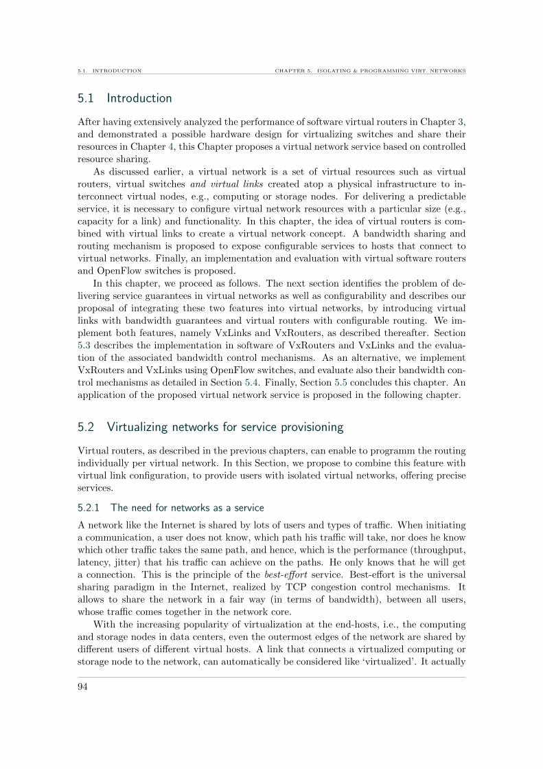
5.1. INTRODUCTION CHAPTER 5. ISOLATING & PROGRAMMING VIRT. NETWORKS
5.1 Introduction
After having extensively analyzed the performance of software virtual routers in Chapter 3,and demonstrated a possible hardware design for virtualizing switches and share theirresources in Chapter 4, this Chapter proposes a virtual network service based on controlledresource sharing.
As discussed earlier, a virtual network is a set of virtual resources such as virtualrouters, virtual switches and virtual links created atop a physical infrastructure to in-terconnect virtual nodes, e.g., computing or storage nodes. For delivering a predictableservice, it is necessary to configure virtual network resources with a particular size (e.g.,capacity for a link) and functionality. In this chapter, the idea of virtual routers is com-bined with virtual links to create a virtual network concept. A bandwidth sharing androuting mechanism is proposed to expose configurable services to hosts that connect tovirtual networks. Finally, an implementation and evaluation with virtual software routersand OpenFlow switches is proposed.
In this chapter, we proceed as follows. The next section identifies the problem of de-livering service guarantees in virtual networks as well as configurability and describes ourproposal of integrating these two features into virtual networks, by introducing virtuallinks with bandwidth guarantees and virtual routers with configurable routing. We im-plement both features, namely VxLinks and VxRouters, as described thereafter. Section5.3 describes the implementation in software of VxRouters and VxLinks and the evalua-tion of the associated bandwidth control mechanisms. As an alternative, we implementVxRouters and VxLinks using OpenFlow switches, and evaluate also their bandwidth con-trol mechanisms as detailed in Section 5.4. Finally, Section 5.5 concludes this chapter. Anapplication of the proposed virtual network service is proposed in the following chapter.
5.2 Virtualizing networks for service provisioning
Virtual routers, as described in the previous chapters, can enable to programm the routingindividually per virtual network. In this Section, we propose to combine this feature withvirtual link configuration, to provide users with isolated virtual networks, offering preciseservices.
5.2.1 The need for networks as a service
A network like the Internet is shared by lots of users and types of traffic. When initiatinga communication, a user does not know, which path his traffic will take, nor does he knowwhich other traffic takes the same path, and hence, which is the performance (throughput,latency, jitter) that his traffic can achieve on the paths. He only knows that he will geta connection. This is the principle of the best-effort service. Best-effort is the universalsharing paradigm in the Internet, realized by TCP congestion control mechanisms. Itallows to share the network in a fair way (in terms of bandwidth), between all users,whose traffic comes together in the network core.
With the increasing popularity of virtualization at the end-hosts, i.e., the computingand storage nodes in data centers, even the outermost edges of the network are shared bydifferent users of different virtual hosts. A link that connects a virtualized computing orstorage node to the network, can automatically be considered like ‘virtualized’. It actually
94
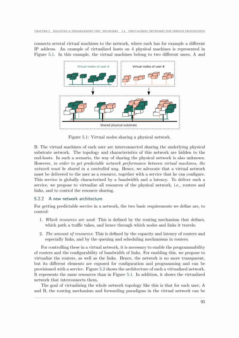
CHAPTER 5. ISOLATING & PROGRAMMING VIRT. NETWORKS 5.2. VIRTUALIZING NETWORKS FOR SERVICE PROVISIONING
connects several virtual machines to the network, where each has for example a differentIP address. An example of virtualized hosts on 4 physical machines is represented inFigure 5.1. In this example, the virtual machines belong to two different users, A and
Shared physical substrate
Virtual nodes of user A Virtual nodes of user B
Figure 5.1: Virtual nodes sharing a physical network.
B. The virtual machines of each user are interconnected sharing the underlying physicalsubstrate network. The topology and characteristics of this network are hidden to theend-hosts. In such a scenario, the way of sharing the physical network is also unknown.However, in order to get predictable network performance between virtual machines, thenetwork must be shared in a controlled way. Hence, we advocate that a virtual networkmust be delivered to the user as a resource, together with a service that he can configure.This service is globally characterized by a bandwidth and a latency. To deliver such aservice, we propose to virtualize all resources of the physical network, i.e., routers andlinks, and to control the resource sharing.
5.2.2 A new network architecture
For getting predictable service in a network, the two basic requirements we define are, tocontrol:
1. Which resources are used: This is defined by the routing mechanism that defines,which path a traffic takes, and hence through which nodes and links it travels;
2. The amount of resources: This is defined by the capacity and latency of routers andespecially links, and by the queuing and scheduling mechanisms in routers.
For controlling these in a virtual network, it is necessary to enable the programmabilityof routers and the configurability of bandwidth of links. For enabling this, we propose tovirtualize the routers, as well as the links. Hence, the network is no more transparent,but its different elements are exposed for configuration and programming and can beprovisioned with a service. Figure 5.2 shows the architecture of such a virtualized network.It represents the same resources than in Figure 5.1. In addition, it shows the virtualizednetwork that interconnects them.
The goal of virtualizing the whole network topology like this is that for each user, Aand B, the routing mechanism and forwarding paradigms in the virtual network can be
95
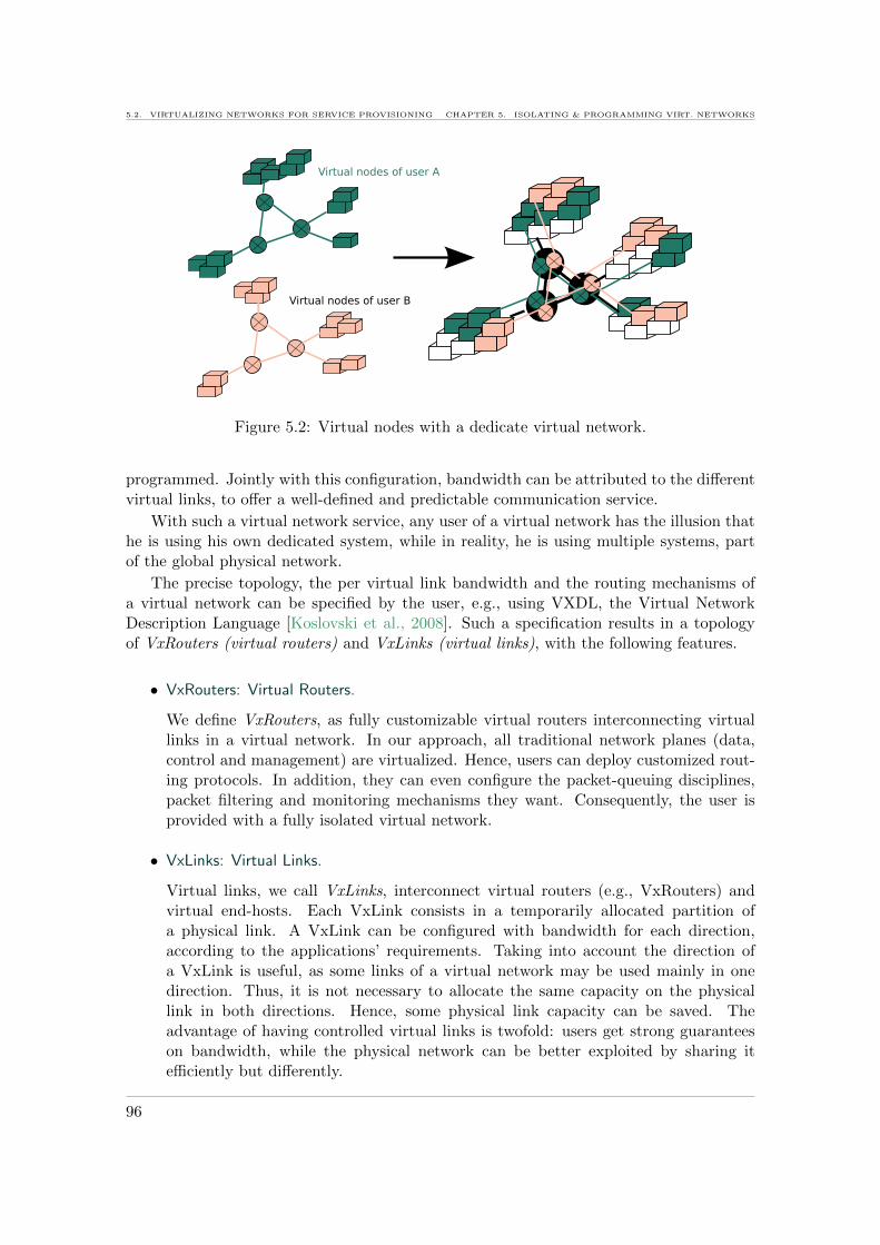
5.2. VIRTUALIZING NETWORKS FOR SERVICE PROVISIONING CHAPTER 5. ISOLATING & PROGRAMMING VIRT. NETWORKS
Virtual nodes of user A
Virtual nodes of user B
Figure 5.2: Virtual nodes with a dedicate virtual network.
programmed. Jointly with this configuration, bandwidth can be attributed to the differentvirtual links, to offer a well-defined and predictable communication service.
With such a virtual network service, any user of a virtual network has the illusion thathe is using his own dedicated system, while in reality, he is using multiple systems, partof the global physical network.
The precise topology, the per virtual link bandwidth and the routing mechanisms ofa virtual network can be specified by the user, e.g., using VXDL, the Virtual NetworkDescription Language [Koslovski et al., 2008]. Such a specification results in a topologyof VxRouters (virtual routers) and VxLinks (virtual links), with the following features.
• VxRouters: Virtual Routers.
We define VxRouters, as fully customizable virtual routers interconnecting virtuallinks in a virtual network. In our approach, all traditional network planes (data,control and management) are virtualized. Hence, users can deploy customized rout-ing protocols. In addition, they can even configure the packet-queuing disciplines,packet filtering and monitoring mechanisms they want. Consequently, the user isprovided with a fully isolated virtual network.
• VxLinks: Virtual Links.
Virtual links, we call VxLinks, interconnect virtual routers (e.g., VxRouters) andvirtual end-hosts. Each VxLink consists in a temporarily allocated partition ofa physical link. A VxLink can be configured with bandwidth for each direction,according to the applications’ requirements. Taking into account the direction ofa VxLink is useful, as some links of a virtual network may be used mainly in onedirection. Thus, it is not necessary to allocate the same capacity on the physicallink in both directions. Hence, some physical link capacity can be saved. Theadvantage of having controlled virtual links is twofold: users get strong guaranteeson bandwidth, while the physical network can be better exploited by sharing itefficiently but differently.
96
CHAPTER 5. ISOLATING & PROGRAMMING VIRT. NETWORKS 5.2. VIRTUALIZING NETWORKS FOR SERVICE PROVISIONING
This de-materialization of routers and links enables to define specific routing and band-width services on a per-virtual network basis. These are described in the following.
5.2.3 A virtual network routing service
Building virtual networks with virtual routers, the path the traffic takes across the vir-tual network can be configured differently for each virtual network. Virtualizing routersto enable their configuration has a similar goal than the overlay network approach (seeSection 2.3.3 of Chapter 2). But instead of controlling the network from the edges, virtu-alization allows to control the nodes inside the network, the VxRouters.
Customized routing and traffic-engineering functions can be set up on the VxRouters.A user can, for example, choose to adapt the routing of his virtual network in order tosatisfy specific Quality of Service requirements, as illustrated in Figure 5.3.
Figure 5.3: Example of bandwidth allocation for latency-sensitive and high-bandwidthflows.
In this example, latency-sensitive traffic and bandwidth-aware traffic are routed ondifferent paths. 1 Gb/s links are allocated between each one of the three VxRouters totransmit latency sensitive traffic. All high-throughput traffic, which can be pipelined, isredirected over Site 2. The advantage of this routing scheme is that the user needs toprovision only 2 links with 5 Gb/s instead of 3. As presented in [Divakaran and Vicat-Blanc Primet, 2007], this is an example of efficient channel provisioning combining routingand traffic engineering. To realize such a scenario, a bandwidth service on VxLinks isrequired. Such a service is defined below.
5.2.4 A virtual network bandwidth service
Virtual networks share a physical substrate network. For ensuring their isolation in termsof performance, the resource sharing between different virtual networks needs to be finelycontrolled. This consists in particular in the link and hence bandwidth sharing.
For enabling a the control of bandwidth on VxLinks, we defined different services. Avirtual network user can request bandwidth Rreq per VxLink, associated to one of theseservices, defined as:
• Guaranteed minimum: The user specifies Rreq, as the minimum rate that has to beavailable on the VxLink at any moment. The service must ensure that the allocatedrate Ralloc is always at least equal to this specified minimum:
97

5.2. VIRTUALIZING NETWORKS FOR SERVICE PROVISIONING CHAPTER 5. ISOLATING & PROGRAMMING VIRT. NETWORKS
Ralloc ≥ Rreq
• Allowed maximum: The user specifies Rreq as the maximum capacity the VxLinkmust provide at any moment. The service must ensure that the allocated rate Ralloc
never exceeds this maximum:
Ralloc ≤ Rreq
• Static reservation: The user specifies Rreq as the exact capacity required on theVxLink. The service must ensure that exactly this capacity is allocated as Ralloc:
Ralloc = Rreq
Specifying bandwidth and one or several of these services (minimum guaranteed, max-imum allowed) per VxLink, a user can obtain QoS for applications he executes over thenetwork, typically distributed applications, e.g., running on Grids and Clouds. For exam-ple, a user who wants to execute a distributed application communicating with MPI couldspecify a guaranteed minimum rate which can not be decreased during negotiation. If theuser specifies an allowed maximum, the negotiation will result in a bandwidth equal orbelow this maximum. This link is shared in a best-effort way with other traffic. Specifyinga static rate gives the user the impression that he works in a dedicated physical networkwhose links have the specified capacity. He will be able to obtain the specified bandwidthat any moment but can never exceed it. This kind of service allows no negotiation andcould for example help with conducting reproducible experiments where link availabilitydoes not vary.In addition, buffer queue lengths and hence delay in routers are critical to the executiontime of distributed applications. Hence, following the model to adjust input rate on arouter to control its buffer queue length, proposed in [Zitoune et al., 2009], we could ad-just VxLink rate depending on the size of the VxRouter queues, in order to minimizepacket loss and control delay. In fact, by dynamically adjusting VxLink bandwidth, theexecution time of distributed applications can be controlled as shown in the next chapter.
The above described bandwidth service is implemented as follows. When a user re-quests a VxLink with a particular bandwidth and service, a decision needs to be takenon the ability to map a virtual network on the physical underlay in a way to provide therequested bandwidth and the associated service. When a virtual network is deployed, ratecontrol is activated or configured to i) guarantee the desired minimum rate and/or ii) limitthe rate to the desired maximum for each VxLink. To guarantee a minimum rate on aphysical link, all the concurrent virtual links using it are limited.
Let C be the capacity of the link, N the number of VxLinks sharing it, mreq(i) andMreq(i) be respectively the minimum and the maximum requested bandwidth of VxLink i.A bandwidth Ralloc(i) needs to be allocated to the VxLink so that mreq(i) ≤ Ralloc(i) ≤Mreq(i). In this case, we consider that the best solution is to maximize Ralloc, so asto improve performance for the user and revenue for the link operator. Yet, many otherstrategies are possible to allocate bandwidth on virtual links, according to different criteria.
98

CHAPTER 5. ISOLATING & PROGRAMMING VIRT. NETWORKS 5.2. VIRTUALIZING NETWORKS FOR SERVICE PROVISIONING
But for maximizing Ralloc for all VxLinks sharing a physical link, the resulting objectivefunction is:
Maximize
N∑i=1
Ralloc(i)
subject to mreq(i) ≤ C −∑
j∈[1,N ],j 6=i
Ralloc(j), ∀i ∈ [1, N ]
mreq(i) ≤ Ralloc(i) ≤Mreq(i),∀i ∈ [1, N ]
N∑i=1
mreq(i) ≤ C
(5.1)
Given the user specifications for each VxLink i sharing the link, mreq(i) and Mreq(i) (bydefault, mreq(i) = 0 and Mreq(i) = C), the optimum values for the maximum bandwidth(Ralloc(i)) per VxLink are calculated.
The following example will illustrate such an allocation schema: An available capacityof 2 Gb/s on a physical links is shared by three VxLinks. For VxLinks 1 and 2, the usersrequest respectively a minimum (mreq) of 100 Mb/s and 800 Mb/s and a maximum (Mreq)of 500 Mb/s and 1500 Mb/s. For VxLink 3, the user makes a static reservation of mreq =Mreq = 300 Mb/s. At timestamp t1, all of those three VxLinks are running. At timestampt2, VxLink 3 decommissions and only VxLinks 1 and 2 remain, so the rate allocations arerecalculated. The allocation is calculated according to the objective function 5.1, usingthe simplex algorithm. The resulting allocation is illustrated in Table 5.1.
VxLink 1 VxLink 2 VxLink 3
t1 mreq 100 800 300(VxLinks 1-3 Mreq 500 1500 300allocated) Ralloc 500 1200 300
t2 mreq 100 800(VxLinks 1-2 Mreq 500 1500allocated) Ralloc 500 1500
Table 5.1: Rate allocated per VxLink (Mb/s).
In this example, during the first phase, from t1 to t2, all the virtual links can get thedesired minimum rate, but it is not possible to allocate the maximum desired rate foreach one. So VxLink 2 can attempt only a rate of 1200 Mb/s instead of 1500 Mb/s. Att2, VxLink 3 finishes, and VxLinks 1 and 2 can share the remaining bandwidth. Fromthis moment on, both VxLinks 1 and 2 can use their maximum desired bandwidth on thespecified VxLinks.
According to these user specifications and the free capacity on the physical substrate,a static bandwidth reservation is made. Then, the control mechanism allocates the max-imum bandwidth for each virtual link in order to guarantee the negotiated bandwidth.The configuration takes place on both ends of the virtual link configuring the physicalinterfaces, depending on the concerned direction of the VxLink.
99

5.3. IMPLEMENTATION IN SOFTWARE CHAPTER 5. ISOLATING & PROGRAMMING VIRT. NETWORKS
Our analysis in Chapter 3 has demonstrated that modern virtualization techniques areimproving rapidly, making the VxRouter approach if software interesting and promising.Yet, maximum link rate can not be expected on all hardware. Hence, an upper limit needsto be set to the available rate.
The next section gives two types of different implementations of VxRouters and VxLinks.We developed software modules that help deploying VxRouters and VxLinks on top of twodifferent types of hardware. The first allows to deploy VxRouters and VxLinks on com-modity hardware installed with Xen. Later, a software module has been implemented tomanage virtual routers also on top of OpenFlow [McKeown et al., 2008] switches. Therate control mechanisms in both implementations are further evaluated.
5.3 Implementation in software
This first section describes our analysis and implementation of the mechanisms that allowto control VxLink bandwidth. VxLinks interconnect VxRouters and both are implementedin software.
5.3.1 Implementation of virtual routers and links
In this first implementation, VxRouters are instantiated inside Xen virtual machines, asdescribed in Chapter 3. This gives us the necessary flexibility to experiment and implementrate control mechanisms to provide bandwidth guarantees on VxLinks.
For controlling the rate of a VxLink, we choose among software rate limiting tech-nologies, especially those provided by the Linux traffic control tool [TC]. Differentlocations can be identified inside the physical machine installed with Xen that host theVxRouters, where rate control can take place. Considering the path of a packet throughthe physical machine as represented in Figure 5.4, there are four possible places on thispath to implement traffic control:
1) At the ingress of the physical interface of the physical machine (dom0);
2) At the egress of the virtual interface of dom0;
3) At the egress of the virtual interface of the VxRouter (domU);
4) At the egress of the physical interface of the physical machine (dom0).
Figure 5.4: Potential locations of rate-control mechanisms in a virtual router.
100

CHAPTER 5. ISOLATING & PROGRAMMING VIRT. NETWORKS 5.3. IMPLEMENTATION IN SOFTWARE
Limiting rate at the incoming physical interface (1) with the traffic control ingress policywould result in dropping packets when the allocated bandwidth is exceeded. This solutionis unsatisfactory, causing too much packet loss when the traffic is bursty. Instead, shapingmechanisms would be preferable for controlling the traffic rates on VxLinks. Limitingat the outgoing virtual interfaces of dom0 seems to be a good solution, as the trafficis shaped as soon as possible, before even entering the virtual routers. Limiting at theoutgoing virtual interface of the virtual routers would be a solution too, but shaping assoon as possible, i.e., before entering the virtual router, would be preferable. The lastshaping opportunity occurs at the outgoing physical interface of dom0 (4), before thepackets leave the interface. The advantage, compared with solutions 1, 2, and 3, is thatthe shaping function knows the traffic of all the VxLinks, since it is concentrated on thisinterface. This could help in adapting the treatment of one VxLink’s traffic according tothat of the other VxLinks. We thus focus on limiting the traffic at the outgoing interfacesof dom0, either the virtual ones or the physical ones. To shape the traffic on the physicalinterface, a classful queuing discipline is required in order to treat the traffic of each VxLinkas a different class.
5.3.2 Evaluations
This section presents experimental results on the rate control on VxLinks implementedin software, as described above. Bandwidth provisioning and performance isolation areinvestigated. To instantiate virtual end hosts and virtual routers, Xen is used. All theexperiments are executed within the Grid’5000 [Cappello et al., 2005] platform, usingXen 3.2 and IBM Opteron servers with one 1 Gb/s physical interface each. The machineshave two CPUs (one core each).
The goal of these experiments is to evaluate the isolation between several VxRouters,and between several VxLinks when they share physical devices.
5.3.2.1 Experimental setup
Two VxRouters, VR1 and VR2 share one physical machine to forward the traffic of twodifferent virtual networks (VNet 1 and 2). Each VxRouter i is connected to four vir-tual nodes (VN) through four VxLinks (VLi,1, VLi,2, VLi,3 and VLi,4). This setup isrepresented in Figure 5.5.
VR2
VR1
VN1,2
VN2,1
VN2,2 VN2,4
VN2,3
VN1,4
VN1,3VN1,1
VL2,3
VL2,4VL2,2
VL2,1
VL1,2 VL1,4
VL1,3VL1,1
Figure 5.5: Experimental setup with 2 VxRouters (VR) hosted on a single physical ma-chine. Each VR interconnects 4 virtual end-hosts (VN), each located on a dedicatedphysical machine, through VxLinks (VL) with different bandwidth requirements.
Each VxLink VLi,j is configured to allow a maximum bandwidth Ri,j . The valueswe use for Ri,j in these experiments are given in Table 5.2. We distinguish user traffic
101

5.3. IMPLEMENTATION IN SOFTWARE CHAPTER 5. ISOLATING & PROGRAMMING VIRT. NETWORKS
following three different profiles:
VL1,1 VL1,3 VL1,2 VL1,4 VL2,1 VL2,3 VL2,2 VL2,4
Ri,j (Mb/s) 50 50 100 100 100 100 200 200
Table 5.2: Maximum rate Ri,j of each VxLink VLi,j .
1. in-profile traffic: the sum of the traffic sent on VxLink VLi,j is smaller than theallowed maximum rate Ri,j ;
2. limit traffic: the sum of the traffic on sent on VxLink VLi,j is equal to the allowedmaximum rate Ri,j ;
3. out-of-profile traffic: the sum of the traffic sent on VxLink VLi,j exceeds the allowedmaximum rate Ri,j .
This experiment aims at determining if the traffic-control techniques limit the traffic tothe desired rate and if isolation is guaranteed. Isolation means that limit or out-of-profiletraffic on one VxLink should have no impact on the bandwidth available on other VxLinkssharing the same the physical link.
Table 5.3 lists four testcases to validate our implementation. In this experiment, wesuppose a congestion factor (CF) of 0.8 for in-profile traffic which means that traffic issent at 80% of the maximum allowed rate. Limit traffic has a CF of 1 and for out-of-profiletraffic, a CF of 1.2 is chosen.
VNet 1 VNet 2
Case 1 in profile in profileCase 2 limit limitCase 3 in profile limitCase 4 in profile out of profile
Table 5.3: User traffic profiles for different test cases.
We send four flows simultaneously. In VNet 1, flow 1 is sent from host VN1,1 to hostVN1,3, and flow 2 is sent from host VN1,2 to host VN1,4. In VNet 2, flow 1 is sent fromhost VN2,1 to VN2,3, and flow 2 ist sent from host VN2,2 to host VN2,4. We perform oneexperiment using UDP flows and another one using TCP flows. The flows are sent withdifferent rates in each experiment to provoke different congestion factors (CF) per VNet,as specified in Table 5.3.
5.3.2.2 Results
The results of these experiments show that the desired rate on each virtual link can beobtained with our configuration and that out-of-profile traffic does not impact other trafficsharing the same physical link.
In case 1, where all the traffic is in profile, requiring less bandwidth than allowed, eachflow gets its desired bandwidth and no packet loss is detected with UDP. For case 2, all
102

CHAPTER 5. ISOLATING & PROGRAMMING VIRT. NETWORKS 5.3. IMPLEMENTATION IN SOFTWARE
0
50
100
150
200
250
300
350
10 20 30 40 50 60
Rate
(M
b/s
)
Time (s)
VNet1 flow1 (50 Mb/s)VNet1 flow2 (100 Mb/s)VNet2 flow1 (100 Mb/s)VNet2 flow2 (200 Mb/s)
Figure 5.6: Test case 2: TCP Rate with VNet 1 and 2 being at the limit rate (with acongestion factor(CF) of 1).
flows try to get 100% of the maximum available bandwidth. This causes some sporadicpacket losses which cause some instantaneous throughput decreases in TCP as illustratedin Figure 5.6. The overall throughput still reaches the allowed maximum value. For testcase 3, where the traffic of VNet 1 is sent in profile and the traffic of VNet 2 at limit rate,none of the flow experiences packet loss like in case 1.
Figures 5.7 and 5.8 show respectively the results with TCP and UDP flows in test case4 where the two flows of VNet 1 are in profile. Their overall congestion factor correspondsto 0.8. They are sent at respective rates of 30 and 90 Mb/s, corresponding to a totalof 120 Mb/s. The allowed bandwidth on the VxLinks is equal to respectively 50 and100 Mb/s. With TCP and UDP, both flows attempt their desired rate and with UDP, noloss is detected. The two flows of VNet 2 try to exceed the allowed value of 300 Mb/s bysending at 120 + 240 = 360 Mb/s. As a result, they see some of their packets dropped atthe incoming interface of the physical router. TCP reacts in a sensitive way to this packetdrop. It tries to share the available bandwidth by the two flows. So flow 1 gets generallythe 120 Mb/s as it is less than half of the available 300 Mb/s. Flow 2 requiring 240 Mb/svaries a lot to get also an average throughput of about half of the 300 Mb/s.
With UDP (Figure 5.8), the packet drop of the flows of VNet 2 causes a regulardecrease of the bandwidth. Flow 1 looses on average 13% of its packets and flow 2 anaverage of 18% of its packets. The average of these two values is slightly smaller than thepercentage of exceeding packets (1− (1/1.2) = 16.6%) implied by the congestion factor of1.2. These results show that only flows which try to exceed the fixed limit bandwidth arepenalized in this configuration. In profile and even limit flows are not impacted. In thisway, individual rate sharing is efficient in this model and isolation is guaranteed.
The evaluated mechanisms have been implemented in the HIPerNet framework [1], for
103
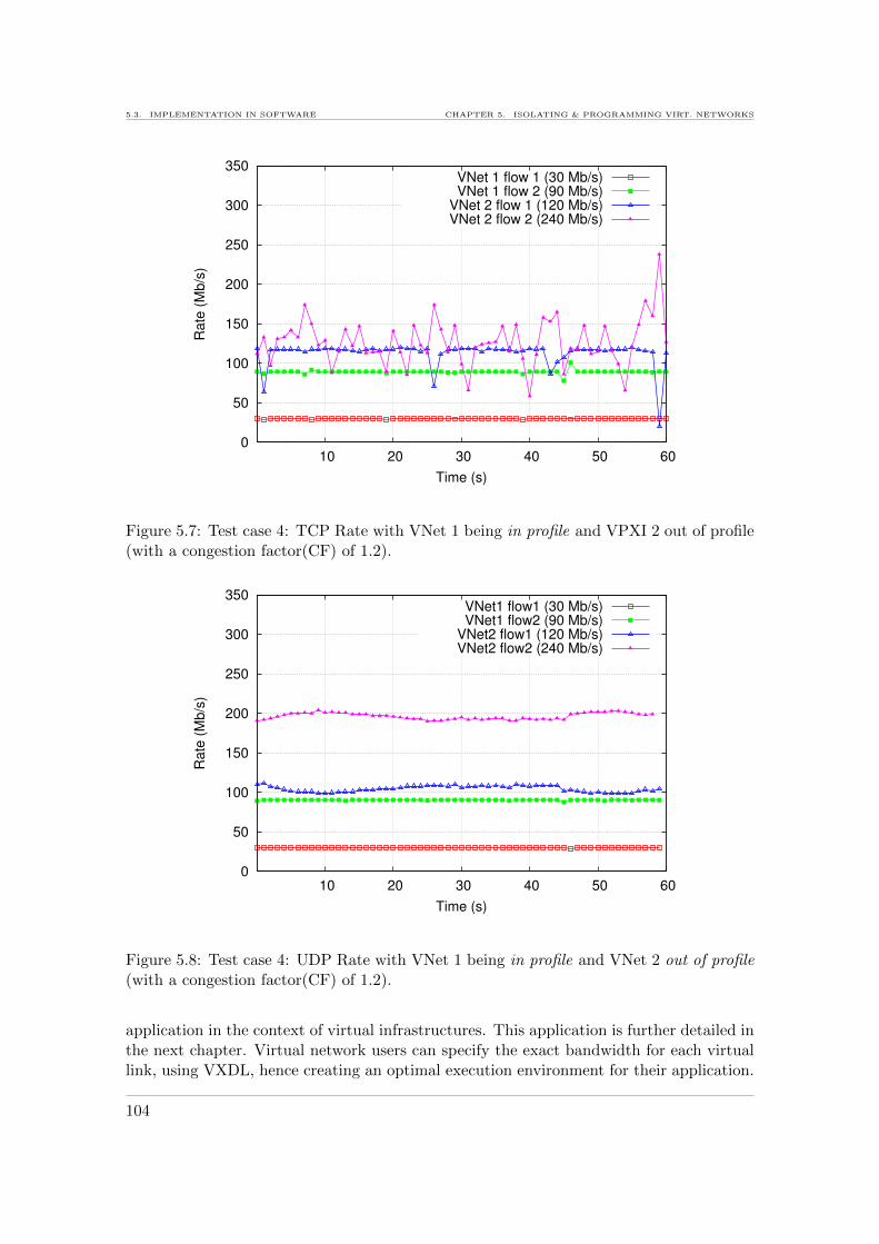
5.3. IMPLEMENTATION IN SOFTWARE CHAPTER 5. ISOLATING & PROGRAMMING VIRT. NETWORKS
0
50
100
150
200
250
300
350
10 20 30 40 50 60
Rate
(M
b/s
)
Time (s)
VNet 1 flow 1 (30 Mb/s)VNet 1 flow 2 (90 Mb/s)
VNet 2 flow 1 (120 Mb/s)VNet 2 flow 2 (240 Mb/s)
Figure 5.7: Test case 4: TCP Rate with VNet 1 being in profile and VPXI 2 out of profile(with a congestion factor(CF) of 1.2).
0
50
100
150
200
250
300
350
10 20 30 40 50 60
Rate
(M
b/s
)
Time (s)
VNet1 flow1 (30 Mb/s)VNet1 flow2 (90 Mb/s)
VNet2 flow1 (120 Mb/s)VNet2 flow2 (240 Mb/s)
Figure 5.8: Test case 4: UDP Rate with VNet 1 being in profile and VNet 2 out of profile(with a congestion factor(CF) of 1.2).
application in the context of virtual infrastructures. This application is further detailed inthe next chapter. Virtual network users can specify the exact bandwidth for each virtuallink, using VXDL, hence creating an optimal execution environment for their application.
104

CHAPTER 5. ISOLATING & PROGRAMMING VIRT. NETWORKS 5.4. IMPLEMENTATION WITH OPENFLOW
5.4 Implementation with OpenFlow
In this second part, as an alternative to the software solution that has scalability issueswhen high network speed is required, as described in Chapter 3, the setup of configurableVxRouters and VxLinks is investigated on OpenFlow switches. These are interestingfor implementing VxRouters, as they allow to configure their flowtables, and hence therouting, as explained in the following. A specific OpenFlow controller was implementedthat enables to manage VxRouters and VxLinks in this type of equipment.
5.4.1 The OpenFlow technology
OpenFlow switches are standard hardware switches that are equipped with a TCAMflowtable, which can be programmed using the OpenFlow protocol [McKeown et al., 2008].This possibility, as described previously in Section 2.4.1.2 of Chapter 2, enables also to im-plement virtualization on such types of switches. In the flowtable, each entry is composedof the three following elements:
• A flow specification: A set of fields specifying a flow. These corresponds to theclassical IP and TCP/UDP header fields in an Ethernet packet;
• Actions: A set of actions to perform on a packet whose header fields match the flow.These actions specify the port to which the packet must be sent out, or can modifyits header, e.g., set a VLAN tag, change the IP address, etc.
• Statistics: Statistics relative to the flow, e.g., how many packets have been received.
A complete specification of the OpenFlow protocol can be found at [OF]. Essentially, anOpenFlow switch allows programming the forwarding of flows according to their layers 2,3 and 4 characteristics.
Messages formatted in the OpenFlow protocol, which are sent to an OpenFlow switchallow to program its flow table, e.g., adding, modifying and deleting one or several entries.They also allow to request information to the switch, for example about the alreadyimplemented flows in the flowtable, or statistic, etc.
Figure 5.9: The OpenFlow concept [OF].
105

5.4. IMPLEMENTATION WITH OPENFLOW CHAPTER 5. ISOLATING & PROGRAMMING VIRT. NETWORKS
The OpenFlow concept is depicted in Figure 5.9. OpenFlow switches can be pro-grammed using so-called controllers that can be written in any programming language, onany general purpose PC, provided that the controller formats all messages to the OpenFlowprotocol, and is connected through a secure TCP connection to the switch. This portingof the control plane out of the box offers enormous flexibility in configuring hardwareswitches.
An OpenFlow switch can route flows based any packet header field. One rule that acontroller could for example set on the OpenFlow switch is “every packet destined to TCPport 80 must leave the switch at port 16”. This allows for example to redirect HTTPtraffic through a specific network paths. But a controller could also run a routing daemonthat takes decision on the IP layer. Hence, it could send rules to the switch like “everypacket destined to IP address 10.12.34.56 must be sent out of port 11”, and so on. Hence,by choosing a header field as a criteria to identify the traffic of a particular virtual network,e.g., a MAC address, an IP address or a VLAN tag, traffic could be routed differently,according this criteria, thus allowing virtualization. Note that this type of virtualizationneeds to be implemented outside the switch, inside the software module that controls theprogramming of the flowtable.
OpenFlow switches can be programmed in two ways: to be active or pro-active. Theactive approach consists in setting up flows on the switch in response to a packet arrival.Actually, when a packet arrives at an OpenFlow switch, and matches no entry of the flowtable, it is by default sent to the controller. Then, based on the information present inthe packet, the controller can decide if it adds an entry to the flow table that matches allthe following packets of the same flow. The flow entry can be set with a timeout, so as todisappear from the flowtable after a certain time. This enables to setup dynamic routingor switching.
The pro-active approach consists in pre-programming the flow table, so that flow entriesalready exist before the first packet of a flow arrives. Packets that do not match any flowentry can be dropped. This is comparable with static routing.
Moreover, depending on the vendor, some OpenFlow switches allow to set up trafficcontrol mechanisms. The latest specification of the OpenFlow protocol includes an actionthat consists in sending packets out to a particular queue. On switches that have portswith several queues, and that allow to setup different rates or priorities on the differentqueues, basic QoS is possible by sending flows explicitly to queues, which have been pre-configured, e.g., via SNMP or directly on the switch. Other vendors propose particularimplementations of QoS. HP proposes for example a specific extension to the OpenFlowprotocol that enables to set up rate limiters, and to send flows explicitly to these ratelimiters [Kim et al., 2010].
Such OpenFlow switches are a very interesting alternative to software routers, as theyare also programmable, even if it is less, but they offer the performance of dedicatedswitching hardware. Actually, there is no virtualization layer that causes overhead duringpacket forwarding.
5.4.2 An OpenFlow controller for a virtual network service
This section describes our investigations on how to build VxRouters inside OpenFlowswitches, and how to control VxLinks interconnecting such VxRouters.
106

CHAPTER 5. ISOLATING & PROGRAMMING VIRT. NETWORKS 5.4. IMPLEMENTATION WITH OPENFLOW
5.4.2.1 VxRouter and VxLink management with OpenFlow
For providing a virtual network service, we propose to use the OpenFlow protocol to setup VxRouters and VxLinks on OpenFlow switches in the following way:
• VxRouters: VxRouters allocated on a physical device use a partition of its ports,and have a specific routing configuration. Building such VxRouters on top of Open-Flow switches is possible through the configuration of their flowtables. Actually, aVxRouter’s routing table can be translated into a set of rules that correspond toflowtable entries. The subset of ports a VxRouter is allowed to use can also be con-trolled through the flowtable configuration. All the flowtable entries correspondingto a specific VxRouter must have the output ports set only to the ports allowed tobe manipulated by this VxRouter.Besides, VxRouters implemented on OpenFlow switches are no more limited to per-form layer 3 routing. We keep the name as routers, but what they actually do isforwarding the traffic on any criteria that can be specified by OpenFlow, i.e., layer2, 3 or 4 packet header fields. Note that layer 1 is also included in specific OpenFlowimplementations for optical equipment [Das et al., 2010]. In summary, we define aVxRouter on an OpenFlow switch by a set of forwarding rules.
• VxLinks: In order to implement VxLinks with specific capacities between VxRoutersallocated on OpenFlow switches, rate control must be performed on the Open-Flow switches for guaranteeing the requested rate on each VxLink. Rate controlon switches output ports can be performed through queuing. The OpenFlow proto-col enables to send packets of a particular flow to a specific queue of an output port.Hence, it is possible to send all flows that are supposed to use the same VxLink, tothe same queue that is configured with the rate required by the VxLink.As an alternative to queuing, rate limiting tools are provided by the extended Open-Flow implementation in HP switch’s firmware. This extension consists in the abilityto set up rate limiters on the switch that are independent of ports, and that limit alltraffic that is sent through them to a specific maximum rate. These rate limiters areimplemented in hardware. An additional action in the OpenFlow protocol allowsto send flows through these rate limiters. We set up one rate limiter per port andper VxLink, and all flows that use a VxLink are sent though the corresponding ratelimiter. This enables bandwidth isolation between VxLinks.
For configuring VxRouters and VxLinks on OpenFlow switches, as described above, wedeveloped a controller module that allows to translate generic VxRouter or VxLink config-urations into OpenFlow configurations. This module interfaces with a generic VxRouterand VxLink configuration module, responsible for configuring virtual networks. The roleof the OpenFlow controller in configuring virtual networks is represented in Figure 5.10.Creating and managing VxRouters and VxLinks consists on the one hand in sending con-figurations to the physical devices, here the OpenFlow switch, to configure them. Genericrequests we term ‘create VxRouter’ or ‘create VxLink’ must be translated into OpenFlowprotocol specific flow or rate limiter configuration requests together with a flow or ratelimiter specification. We simplify these as ‘add flow’ and ‘add rate limiter’ on Figure 5.10.The controller is responsible for this translation. On the other hand, the management ofvirtual networks consists also in retrieving information from the VxRouters and VxLinks
107

5.4. IMPLEMENTATION WITH OPENFLOW CHAPTER 5. ISOLATING & PROGRAMMING VIRT. NETWORKS
OF switch
create VxLink
create VxRouter
add rate limiter
add flow
OpenFlow
Protocol
VNet service
Specification
OF controller
Virtual network manager
Figure 5.10: VxRouter and VxLink management module for translating virtual network(VNet) service specifications to OpenFlow (OF) switches.
either by sending requests to get the device status, or by receiving spontaneous messagesfrom the device. For handling these two functionalities when managing virtual networks,we implemented the specific controller module described in the following.
5.4.2.2 Controller architecture
For sending configurations to the switches, as well as receiving on replies or sponteniousmessages from the switches, e.g., resource states, the controller must be running perma-nently. It listens to messages from the switch to propagate them upwards, as well as tomessages from the virtual network manager, to propagate them downwards, to the switch.The controller’s role is also to ensures synchronization of the data between VxRouters’s in-ternal data and the switch configuration, e.g., between the routing tables of all VxRouters,and the flowtable of the switch.
We built the controller using the library provided within the reference controller thatis released within Open vSwitch [OVS]. This library provides all the necessary primitivesto setup connections between controller and switches, and to send messages to the switchand receive messages from the switch. Hence, OpenFlow messages, formed according toVxRouter and VxLink configurations, can be sent to the switch, and status messagescan be read from the switch and be exposed to the upper layer, the VxRouter or virtualnetwork management layer. The controller performs these two tasks in parallel, listeningto the switch, and listening to VxRouter configuration messages, or information requests,as represented in Figure 5.11. Typically, when a VxRouter configuration is issued by theVxRouter manager, and requests to the controller to add a route, the controller sends anadd flow message to the OpenFlow switch, and then a get flow info message to ask for thepresence of the flow. Then it waits until the process listening on the switch returns thereply and according to the information, sends back to the VxRouter manager if the flowcould be added successfully or not. This additional check is performed in order to be surethe route could be added and information is consistent between the internal data of theVxRouter manager and the actual switch flowtable.
108

CHAPTER 5. ISOLATING & PROGRAMMING VIRT. NETWORKS 5.4. IMPLEMENTATION WITH OPENFLOW
OF controller
OF switch
− setup configuration
Listen to requests to
− get information
Send information
− Replys to requests
− Status/Errors
− setup configuration
Listen to requests to
− get information
Send information
− ACKs to requests
− Status/Errors
− Replys to requests
Manager
VxRouter/VxLink
Figure 5.11: OpenFlow controller interacting with VxRouter and VxLink manager andthe switch.
5.4.2.3 Alternative implementations
An existing solution for virtualizing an OpenFlow switch is FlowVisor [Sherwood et al.,2010]. FlowVisor operates as a proxy between one or several OpenFlow switches and oneor several controllers. It allows different controllers to control different subsets of flows onthe same switch, hence virtualizing the latter. For example, one controller could controlonly HTTP flows. Another controller could control for example only flows that enter atports 1 to 7 of a switch, etc. Any type of filtering based on the packet header fields ispossible. Controllers connect to FlowVisor and get the impression that they are directlyconnected to the switch. FlowVisor then sends the OpenFlow messages from the controllerto the switch. The messages coming from the switch are also sent to FlowVisor, whichdistributes them to the responsible controller. This is useful if several independent entitieswant to run their own controllers on a single OpenFlow switch.
In our first VxRouter implementation, the VxRouter manager itself is in charge ofperforming the virtualization. It is actually the only entity that controls and configuresall the VxRouters of a switch, and hence does some of the tasks of FlowVisor. Beforesending a request to the controller, it verifies that the required configuration does notconflict with another VxRouter’s configuration.
In a further version of a VxRouter manager that includes the possibility for users todeploy their own OpenFlow controllers (e.g., we could imagine a separate controller perVxSwitch, say a VxController) it could be interesting to use FlowVisor. It could dividethe OpenFlow messages between such VxControllers and the default OpenFlow controllerwe use presently for pre-configured VxRouters. However, this would require to configureFlowVisor in a way to make sure, that different VxControllers could not configure thesame entries in the flowtable.
Regarding the controller, NOX [Gude et al., 2008] is the most popular existing plat-form, which operates like a network operating system, able to control a network of switches.It features an API, which enables developing controller modules using simplified primi-
109
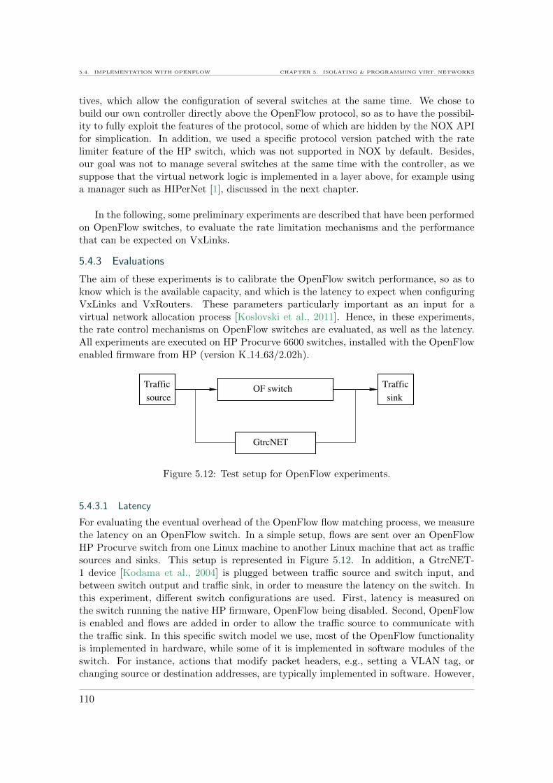
5.4. IMPLEMENTATION WITH OPENFLOW CHAPTER 5. ISOLATING & PROGRAMMING VIRT. NETWORKS
tives, which allow the configuration of several switches at the same time. We chose tobuild our own controller directly above the OpenFlow protocol, so as to have the possibil-ity to fully exploit the features of the protocol, some of which are hidden by the NOX APIfor simplication. In addition, we used a specific protocol version patched with the ratelimiter feature of the HP switch, which was not supported in NOX by default. Besides,our goal was not to manage several switches at the same time with the controller, as wesuppose that the virtual network logic is implemented in a layer above, for example usinga manager such as HIPerNet [1], discussed in the next chapter.
In the following, some preliminary experiments are described that have been performedon OpenFlow switches, to evaluate the rate limitation mechanisms and the performancethat can be expected on VxLinks.
5.4.3 Evaluations
The aim of these experiments is to calibrate the OpenFlow switch performance, so as toknow which is the available capacity, and which is the latency to expect when configuringVxLinks and VxRouters. These parameters particularly important as an input for avirtual network allocation process [Koslovski et al., 2011]. Hence, in these experiments,the rate control mechanisms on OpenFlow switches are evaluated, as well as the latency.All experiments are executed on HP Procurve 6600 switches, installed with the OpenFlowenabled firmware from HP (version K 14 63/2.02h).
OF switch
source
Traffic
sink
Traffic
GtrcNET
Figure 5.12: Test setup for OpenFlow experiments.
5.4.3.1 Latency
For evaluating the eventual overhead of the OpenFlow flow matching process, we measurethe latency on an OpenFlow switch. In a simple setup, flows are sent over an OpenFlowHP Procurve switch from one Linux machine to another Linux machine that act as trafficsources and sinks. This setup is represented in Figure 5.12. In addition, a GtrcNET-1 device [Kodama et al., 2004] is plugged between traffic source and switch input, andbetween switch output and traffic sink, in order to measure the latency on the switch. Inthis experiment, different switch configurations are used. First, latency is measured onthe switch running the native HP firmware, OpenFlow being disabled. Second, OpenFlowis enabled and flows are added in order to allow the traffic source to communicate withthe traffic sink. In this specific switch model we use, most of the OpenFlow functionalityis implemented in hardware, while some of it is implemented in software modules of theswitch. For instance, actions that modify packet headers, e.g., setting a VLAN tag, orchanging source or destination addresses, are typically implemented in software. However,
110

CHAPTER 5. ISOLATING & PROGRAMMING VIRT. NETWORKS 5.4. IMPLEMENTATION WITH OPENFLOW
such type of modifications can be useful in the management of virtual networks. Hence,in a third experiment, we force the traffic to use the software path by modifying one if itsheader fields. In all experiments, traffic consisting in 128 Byte packets is generated usingiperf [IPE].
The results of the three experiments are represented on Figure 5.13. They represent
0
200
400
600
800
1000
1200
0 100 200 300 400 500 600
Late
ncy (
µs)
Time (s)
Not OF enabledOF Hardware pathOF Software path
Figure 5.13: Latency on an OpenFlow enabled switch.
average latencies over intervals of one second. Latency is almost the same on the nonOpenFlow enabled switch, and the OpenFlow enabled switch where the flow is set up inhardware. It corresponds respectively to about 5.8 µs and 6.8 µs for 128 Byte packets.Using the software paths, packets undergo on average a latency of over 200 µs, whichvaries by over 200 µs. Hence, when implementing header field update functionality onVxRouters, the corresponding latency has to be taken into account on this particular typeof switch.
5.4.3.2 Rate limiting
For calibrating the available VxLink capacity, we evaluate, the rate limiting mechanisms.The same test setup is used than the one represented in Figure 5.12, but without usingthe GtrcNET device. Flows are generated using iperf [IPE]. In a first experiments, UDPtraffic is sent at maximum rate through the 1 Gb/s ports of the switch. The experiment isthen repeated with TCP traffic. In the switch, flows are set up to allow the communicationbetween the two hosts, and a rate limiter is set up to limit the traffic of these flows. Themaximum rate of the rate limiter is changed every 10 minutes, starting from 100 Mb/s upto 1000 Mb/s by increments of 100 Mb/s.
Figure 5.14 shows the rate, to which the rate limiter is configured, and the obtainedUDP and TCP throughput. The results obtained correspond to the average rates overone second of data inside maximum sized IP packets (1500 Bytes). Converting these to
111
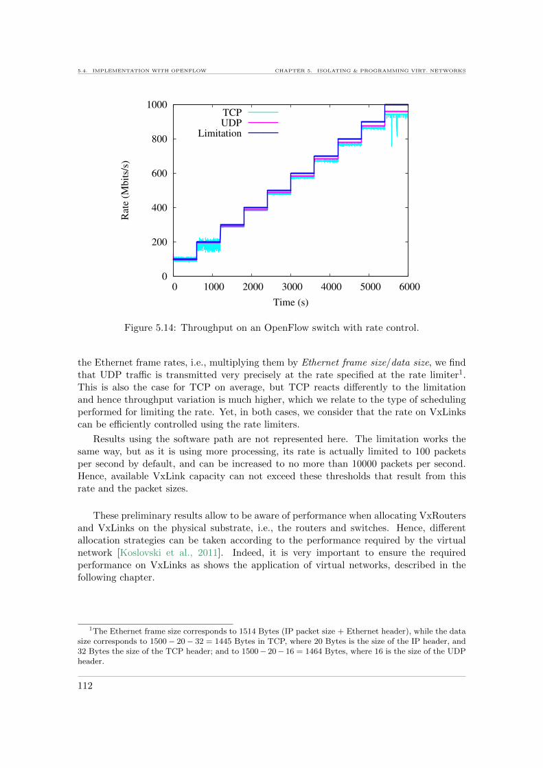
5.4. IMPLEMENTATION WITH OPENFLOW CHAPTER 5. ISOLATING & PROGRAMMING VIRT. NETWORKS
0
200
400
600
800
1000
0 1000 2000 3000 4000 5000 6000
Rate
(M
bit
s/s)
Time (s)
TCPUDP
Limitation
Figure 5.14: Throughput on an OpenFlow switch with rate control.
the Ethernet frame rates, i.e., multiplying them by Ethernet frame size/data size, we findthat UDP traffic is transmitted very precisely at the rate specified at the rate limiter1.This is also the case for TCP on average, but TCP reacts differently to the limitationand hence throughput variation is much higher, which we relate to the type of schedulingperformed for limiting the rate. Yet, in both cases, we consider that the rate on VxLinkscan be efficiently controlled using the rate limiters.
Results using the software path are not represented here. The limitation works thesame way, but as it is using more processing, its rate is actually limited to 100 packetsper second by default, and can be increased to no more than 10000 packets per second.Hence, available VxLink capacity can not exceed these thresholds that result from thisrate and the packet sizes.
These preliminary results allow to be aware of performance when allocating VxRoutersand VxLinks on the physical substrate, i.e., the routers and switches. Hence, differentallocation strategies can be taken according to the performance required by the virtualnetwork [Koslovski et al., 2011]. Indeed, it is very important to ensure the requiredperformance on VxLinks as shows the application of virtual networks, described in thefollowing chapter.
1The Ethernet frame size corresponds to 1514 Bytes (IP packet size + Ethernet header), while the datasize corresponds to 1500 − 20 − 32 = 1445 Bytes in TCP, where 20 Bytes is the size of the IP header, and32 Bytes the size of the TCP header; and to 1500− 20− 16 = 1464 Bytes, where 16 is the size of the UDPheader.
112

CHAPTER 5. ISOLATING & PROGRAMMING VIRT. NETWORKS 5.5. CONCLUSION
5.5 Conclusion
After having built a virtual router prototype in Chapter 3, able to run on commodity hard-ware, we integrated the router to the virtual network concept in order to control routingbetween distributed virtual nodes. As a promising and powerful alternative, virtual routersbased on OpenFlow technology were developed. Moreover, a virtual link (VxLink) con-cept was defined to interconnect virtual routers. Rate control mechanisms were designedand implemented, allowing users to adjust the capacity of VxLinks exactly to the requiredamount at the desired time. The virtual network implementations in software and withOpenFlow were evaluated, and both are able to isolate the traffic of different VxLinks.Virtual routers implemented on OpenFlow switches can deliver higher performance, whilestill offering high configurability. In the following chapter, this virtual network service isapplied to the context of virtual infrastructures with the goal of enabling the precise con-figuration of the network inside virtual infrastructures, and providing strict performanceguarantees.
113

5.5. CONCLUSION CHAPTER 5. ISOLATING & PROGRAMMING VIRT. NETWORKS
114

6Application of virtual networks
6.1 Introduction
6.2 Background on virtual infrastructures
6.2.1 Infrastructures as a Service and the Cloud
6.2.2 Cloud networking
6.3 Network control in virtual infrastructures
6.3.1 Virtual infrastructures on Grid’5000
6.3.2 Implementation in HIPerNet
6.3.3 Evaluation of virtual infrastructure isolation
6.4 Conclusion
Part of the content of this chapter has been published at the 20th ITC SpecialistSeminar 2009 [6], at the Journal of Grid Computing (JoGC 2010) [3] and has beenpresented at the Grid’5000 Spring school 2009 [16]. In addition, a research reporthas been published [12].
Abstract. With the Infrastructure as a Service (IaaS) paradigm and the Clouds,geographically distributed virtual IT (computing and storage) resources can be requestedon demand. The interconnection network plays an important role in the quality of servicedelivered. This chapter investigates virtual infrastructures combining IT and network. Thepreviously presented virtual network service is used to interconnect virtual infrastructure’sIT resources in a controlled way. A use case and experimental validation show the resultingisolation and its impact on the performance of virtual infrastructures.
Application
115
6.1. INTRODUCTION CHAPTER 6. APPL. OF ISOLATED VIRT. NETWORKS
6.1 Introduction
The concept of virtual infrastructures has emerged from the virtualization of end-hosts,and the convergence of computing and communication. The Internet is not only a blackbox providing pipes between edge machines, but has become a world-wide reservoir in-creasingly embedding computational and storage resources to meet the requirements ofemerging applications [RES, 2008]. The promising vision of grid computing—to bringtogether geographically distributed resources to build large-scale computing environmentsfor data- or computing-intensive applications—and the service wave led naturally to the”Infrastructure as a Service” (IaaS) paradigm [IaaS, 2008].
Currently, virtual infrastructures, e.g., those enabled by Clouds, are composed of vir-tual computing and storage nodes. These virtual infrastructures have two limitations: i)they share the network that interconnects them in an uncontrolled way, and ii) the networkis not included in the service and not exposed to the user for configuration. Thus, usershave no control neither on the path their traffic uses, nor on the fraction of bandwidth itgets. This can result in unpredictable performance of applications that use the networkfor communication among several virtual computing and storage nodes. This is exactlywhere the virtual network service proposed in the previous chapter can come as a solution.
Hence in this chapter, we proceed as follows. First, Section 6.2 describes the context.The concept of virtual infrastructures as a service is detailed and the problem of providingnetwork services in such infrastructures is identified. Then, in Section 6.3, we describeour proposal of integrating network control to virtual infrastructures using the virtualnetwork service we presented in the previous chapter. This proposal includes first theimplementation of the virtual network service on Grid’5000 in the context of the HIPerNetvirtual infrastructure manager. Moreover, it includes the validation of this service, witha focus on performance isolation in virtual infrastructures. This validation is performedthrough experimentation with a large-scale distributed application.
6.2 Background on virtual infrastructures
A virtual infrastructure is a set of virtual resources, such as computing and storage nodes,which are interconnected. For example, the data-centers of companies are virtualizedtoday. Data-bases, web servers, file servers, etc., are hosted on virtual machines to decreasethe hardware cost and need for maintenance. Such a set of virtual machines is a typicalexample of a virtual infrastructure that emerged with the expansion of server virtualizationtechnologies. Today, this concept is pushed further towards virtual infrastructures hostedsomewhere in the Cloud that are exposed as a service.
6.2.1 Infrastructures as a Service and the Cloud
An emerging concept of the IT world is the ”Everything as a Service” paradigm, abbrevi-ated as XaaS, where software as well as hardware and its administration, and managementare available on demand—as a service.
New software models provide software over the web as a service (SaaS) [Turner et al.,2003]. Hence, users do need only a minimal local configuration to run the software. Also,they do not need to administer it, which is provided by the service. They only just use it.This trend evolved further towards Platforms as a Service (PaaS), which makes a whole
116

CHAPTER 6. APPL. OF ISOLATED VIRT. NETWORKS 6.2. BACKGROUND ON VIRTUAL INFRASTRUCTURES
platform available for users, containing different underlying hardware and the tools to useit. This service model goes along with the recent trends in outsourcing to the Cloud.Clouds have been defined in [Mell and Grance, 2009]. A Cloud consists basically in a setof computing resources, distributed over different geographical locations or sites. Thesecomputing resources are in general organized in virtual machines, due to their flexibilityand ease of reconfiguration over time. The Cloud concept emerged together with the Gridconcept, and the increasing bandwidth on the Internet.What is mostly not considered in these services is the network. Users connect to theirsoftware or platform through the public Internet, as they connect anywhere else. They donot get particular performance guarantees. However, as the network is fully involved ineach of these services, it should also be provided to the users as a service, with attributessuch as bandwidth and latency.
The PaaS paradigm has been extended to the Infrastructure as a Service (IaaS)paradigm, where a user can request a whole IT infrastructure as a service, for a givenduration, deploy his data and applications, and start computing. This is what is mostlyprovided by public Clouds, e.g., Amazon [AMA], Microsoft Azure [AZU]. This is typicallythe case of a company that wants to outsource their IT infrastructure. When it comesto infrastructures, not only the network connection towards the users plays an importantrole in the performance of the service, but also the quality of the connection between thedifferent resources of the infrastucture. Here, it is even more important to include thenetwork as a service. Depending on the quality of the service, users may experience dif-ferences, e.g., in processing data that is stored in a data base that is located on a differentresource than the software that uses the data for computing. Especially that oftenly, thedifferent resources are located in the same LAN, hence not traversing the public networkwhere control is difficult.
6.2.2 Cloud networking
The network changed is purpose, especially with the expansion of server virtualizationand the outsourcing to the Clouds [Rosenberg and Mateos, 2010]. It is no more solely adata-transmission facility, but participates in some way in the computing, as data that iscomputed on different virtual machines in a Cloud is exchanged over the network duringthe execution of the application. Figure 6.1 represents a Cloud network of virtual resourcesof two different clients, distributed over different locations.
In such a case, the communication paradigm between these resources becomes of greatimportance. Therefore, new techniques to virtualize the network stack in servers areappearing, as well as new types of switches and routers that are able to deal with parallelnetworks, for virtualized server parks and private Clouds. This is presently possible onlyat the edge or inside LANs with particular QoS configurations. However, this does notcope with the network performance in geographically distributed virtual infrastructures,e.g., on public Clouds.The only service that is offered by the network today is connectivity. Anything else, suchas security, is implemented at the edges. While security at the edge, like crypting data,secures it also while traversing the core, which is not the case of performance. Trafficshaping can also occur at the edges, but what the traffic experiences in the core is hardlypredictable. It is up to now accepted that other users can impact the quality of theconnection to the service.
117
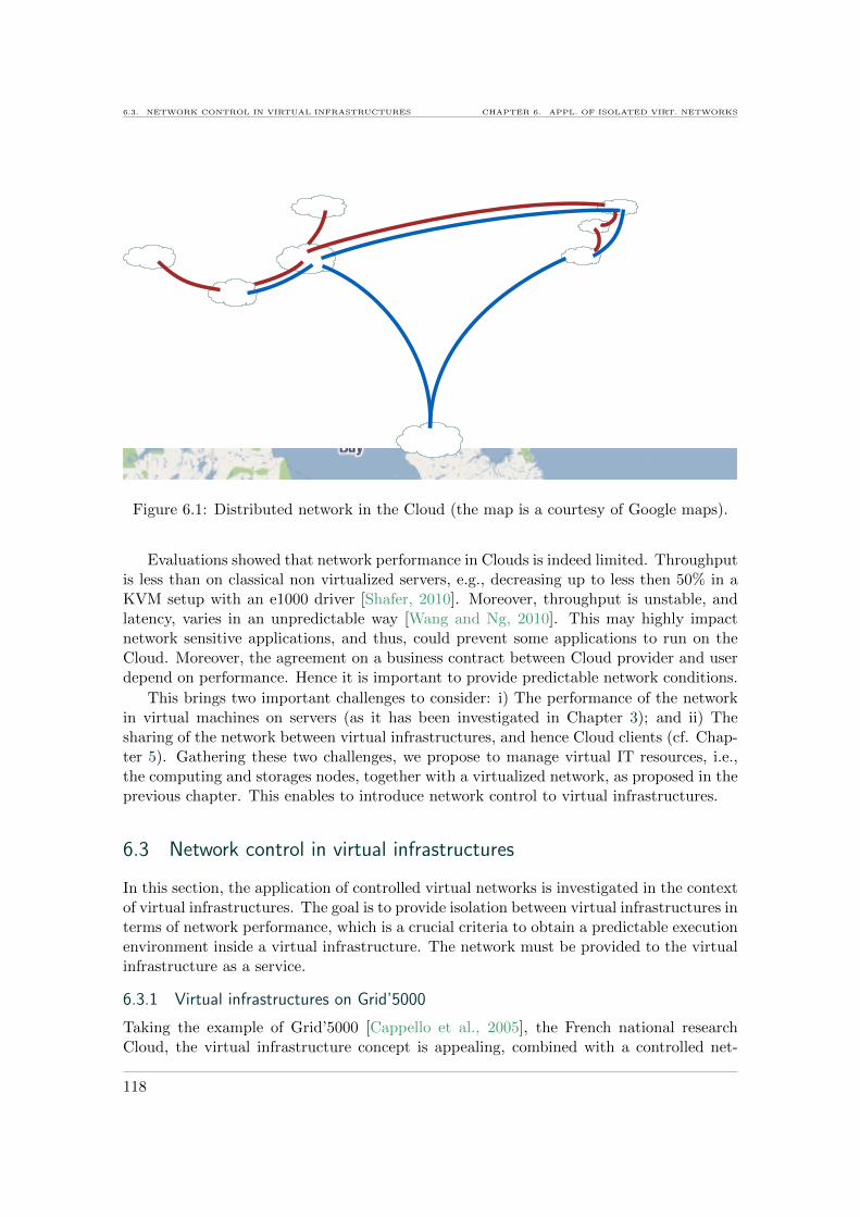
6.3. NETWORK CONTROL IN VIRTUAL INFRASTRUCTURES CHAPTER 6. APPL. OF ISOLATED VIRT. NETWORKS
Figure 6.1: Distributed network in the Cloud (the map is a courtesy of Google maps).
Evaluations showed that network performance in Clouds is indeed limited. Throughputis less than on classical non virtualized servers, e.g., decreasing up to less then 50% in aKVM setup with an e1000 driver [Shafer, 2010]. Moreover, throughput is unstable, andlatency, varies in an unpredictable way [Wang and Ng, 2010]. This may highly impactnetwork sensitive applications, and thus, could prevent some applications to run on theCloud. Moreover, the agreement on a business contract between Cloud provider and userdepend on performance. Hence it is important to provide predictable network conditions.
This brings two important challenges to consider: i) The performance of the networkin virtual machines on servers (as it has been investigated in Chapter 3); and ii) Thesharing of the network between virtual infrastructures, and hence Cloud clients (cf. Chap-ter 5). Gathering these two challenges, we propose to manage virtual IT resources, i.e.,the computing and storages nodes, together with a virtualized network, as proposed in theprevious chapter. This enables to introduce network control to virtual infrastructures.
6.3 Network control in virtual infrastructures
In this section, the application of controlled virtual networks is investigated in the contextof virtual infrastructures. The goal is to provide isolation between virtual infrastructures interms of network performance, which is a crucial criteria to obtain a predictable executionenvironment inside a virtual infrastructure. The network must be provided to the virtualinfrastructure as a service.
6.3.1 Virtual infrastructures on Grid’5000
Taking the example of Grid’5000 [Cappello et al., 2005], the French national researchCloud, the virtual infrastructure concept is appealing, combined with a controlled net-
118

CHAPTER 6. APPL. OF ISOLATED VIRT. NETWORKS 6.3. NETWORK CONTROL IN VIRTUAL INFRASTRUCTURES
work service. It allows researchers to run experiments in confined virtual execution envi-ronments, with predictable network performance.
6.3.1.1 The platform
Grid’5000 [Cappello et al., 2005] is an experimental facility, which gathers large scale clus-ters and gives access to 5000 CPUs distributed over 9 sites and interconnected by 10 Gb/s-dedicated lambdas over the French research and education network RENATER [REN]. Itis actually a typical example of a Cloud gathering several computing clusters located ondifferent geographical sites. This infrastructure is represented in Figure 6.2. Grid’5000
InternetLyon
Paris
Nancy
Lille
Rennes
Bordeaux
Toulouse Nice
Grenoble
Porto Allegre
Luxembourg
10G monomode10G lambda on DWDM Renater 5VPN over Internet
Grid'5000 switch/router
RENATER L2/DWDM device
Cluster of computing nodes
Figure 6.2: Grid’5000 infrastructure.
provides a deep reconfiguration mechanism allowing researchers to deploy, install, boot andrun their specific software images, possibly including all the layers of the software stack.This reconfiguration capability leads to the experiment workflow followed by Grid’5000users: i) reserve a partition of Grid’5000, ii) deploy a software image on the reservednodes, iii) reboot all the machines of the partition using the software image, iv) run theexperiment, v) collect the results and vi) release the machines. Grid’5000 allows users toreserve the same set of resources across successive experiments, to run their experiments ondedicated nodes (obtained by reservation), and to install and run their own experimentalcondition injectors and measurement software.
While computing nodes can be entirely configured and are dedicated to the user whoreserved them, this is not the case for the network. The Grid’5000 backbone, built of10 Gb/s links, is shared by all users in an uncontrolled way. Neither the bandwidth northe routing of the network can be controlled by users. Hence, throughput and jitter arenot predictable and experiments are not reproducible.
In the following, we describe how the controllable virtual networks, proposed in theprevious chapter, can be used in Grid’5000, to expose the network as a reservable, config-urable and controlled resource, just as the nodes are, to enable fully controllable experi-ment infrastructures [6].
119
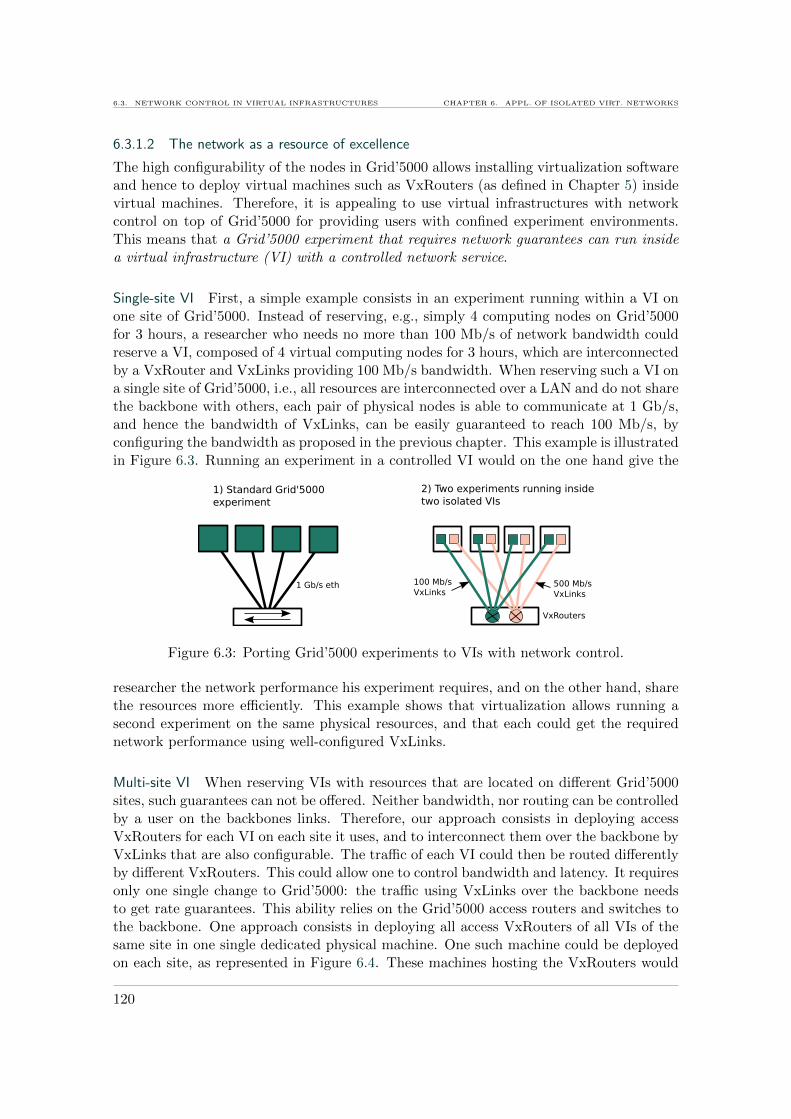
6.3. NETWORK CONTROL IN VIRTUAL INFRASTRUCTURES CHAPTER 6. APPL. OF ISOLATED VIRT. NETWORKS
6.3.1.2 The network as a resource of excellence
The high configurability of the nodes in Grid’5000 allows installing virtualization softwareand hence to deploy virtual machines such as VxRouters (as defined in Chapter 5) insidevirtual machines. Therefore, it is appealing to use virtual infrastructures with networkcontrol on top of Grid’5000 for providing users with confined experiment environments.This means that a Grid’5000 experiment that requires network guarantees can run insidea virtual infrastructure (VI) with a controlled network service.
Single-site VI First, a simple example consists in an experiment running within a VI onone site of Grid’5000. Instead of reserving, e.g., simply 4 computing nodes on Grid’5000for 3 hours, a researcher who needs no more than 100 Mb/s of network bandwidth couldreserve a VI, composed of 4 virtual computing nodes for 3 hours, which are interconnectedby a VxRouter and VxLinks providing 100 Mb/s bandwidth. When reserving such a VI ona single site of Grid’5000, i.e., all resources are interconnected over a LAN and do not sharethe backbone with others, each pair of physical nodes is able to communicate at 1 Gb/s,and hence the bandwidth of VxLinks, can be easily guaranteed to reach 100 Mb/s, byconfiguring the bandwidth as proposed in the previous chapter. This example is illustratedin Figure 6.3. Running an experiment in a controlled VI would on the one hand give the
1 Gb/s eth 100 Mb/sVxLinks
500 Mb/sVxLinks
VxRouters
1) Standard Grid'5000experiment
2) Two experiments running insidetwo isolated VIs
Figure 6.3: Porting Grid’5000 experiments to VIs with network control.
researcher the network performance his experiment requires, and on the other hand, sharethe resources more efficiently. This example shows that virtualization allows running asecond experiment on the same physical resources, and that each could get the requirednetwork performance using well-configured VxLinks.
Multi-site VI When reserving VIs with resources that are located on different Grid’5000sites, such guarantees can not be offered. Neither bandwidth, nor routing can be controlledby a user on the backbones links. Therefore, our approach consists in deploying accessVxRouters for each VI on each site it uses, and to interconnect them over the backbone byVxLinks that are also configurable. The traffic of each VI could then be routed differentlyby different VxRouters. This could allow one to control bandwidth and latency. It requiresonly one single change to Grid’5000: the traffic using VxLinks over the backbone needsto get rate guarantees. This ability relies on the Grid’5000 access routers and switches tothe backbone. One approach consists in deploying all access VxRouters of all VIs of thesame site in one single dedicated physical machine. One such machine could be deployedon each site, as represented in Figure 6.4. These machines hosting the VxRouters would
120
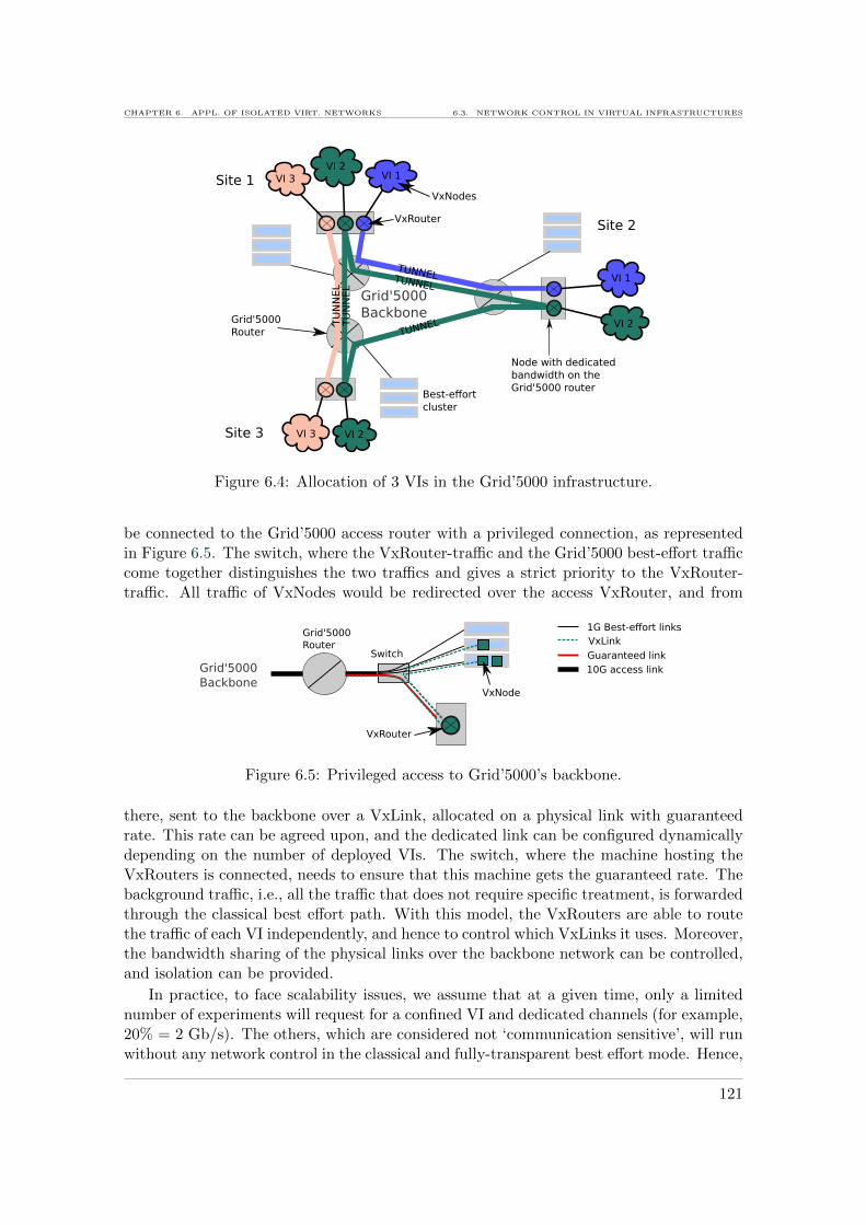
CHAPTER 6. APPL. OF ISOLATED VIRT. NETWORKS 6.3. NETWORK CONTROL IN VIRTUAL INFRASTRUCTURES
Grid'5000Backbone
TUNNELTUNNEL
TUNNELTU
NN
EL
TU
NN
EL
VI 1
VI 1
VI 2
VI 2
VI 2
VI 3
VI 3
VxRouter
VxNodes
Grid'5000Router
Site 1
Site 3
Site 2
Best-effortcluster
Node with dedicatedbandwidth on theGrid'5000 router
Figure 6.4: Allocation of 3 VIs in the Grid’5000 infrastructure.
be connected to the Grid’5000 access router with a privileged connection, as representedin Figure 6.5. The switch, where the VxRouter-traffic and the Grid’5000 best-effort trafficcome together distinguishes the two traffics and gives a strict priority to the VxRouter-traffic. All traffic of VxNodes would be redirected over the access VxRouter, and from
Grid'5000Backbone
VxRouter
Grid'5000Router
1G Best-effort links
Switch
VxNode
VxLink
Guaranteed link10G access link
Figure 6.5: Privileged access to Grid’5000’s backbone.
there, sent to the backbone over a VxLink, allocated on a physical link with guaranteedrate. This rate can be agreed upon, and the dedicated link can be configured dynamicallydepending on the number of deployed VIs. The switch, where the machine hosting theVxRouters is connected, needs to ensure that this machine gets the guaranteed rate. Thebackground traffic, i.e., all the traffic that does not require specific treatment, is forwardedthrough the classical best effort path. With this model, the VxRouters are able to routethe traffic of each VI independently, and hence to control which VxLinks it uses. Moreover,the bandwidth sharing of the physical links over the backbone network can be controlled,and isolation can be provided.
In practice, to face scalability issues, we assume that at a given time, only a limitednumber of experiments will request for a confined VI and dedicated channels (for example,20% = 2 Gb/s). The others, which are considered not ‘communication sensitive’, will runwithout any network control in the classical and fully-transparent best effort mode. Hence,
121
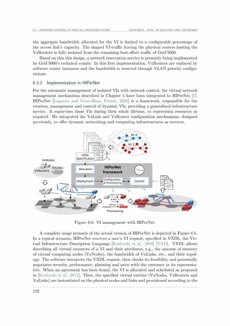
6.3. NETWORK CONTROL IN VIRTUAL INFRASTRUCTURES CHAPTER 6. APPL. OF ISOLATED VIRT. NETWORKS
the aggregate bandwidth allocated for the VI is limited to a configurable percentage ofthe access link’s capacity. The shaped VI-traffic leaving the physical routers hosting theVxRouters is fully isolated from the remaining best-effort traffic of Grid’5000.
Based on this this design, a network reservation service is presently being implementedby Grid’5000’s technical comity. In this first implementation, VxRouters are replaced bysoftware router instances and the bandwidth is reserved through VLAN priority configu-rations.
6.3.2 Implementation in HIPerNet
For the automatic management of isolated VIs with network control, the virtual networkmanagement mechanisms described in Chapter 5 have been integrated to HIPerNet [1].HIPerNet [Laganier and Vicat-Blanc Primet, 2005] is a framework, responsible for thecreation, management and control of dynamic VIs, providing a generalized infrastructureservice. It supervises these VIs during their whole lifetime, to reprovision resources asrequired. We integrated the VxLink and VxRouter configuration mechanisms, designedpreviously, to offer dynamic networking and computing infrastructures as services.
Figure 6.6: VI management with HIPerNet.
A complete usage scenario of the actual version of HIPerNet is depicted in Figure 6.6.In a typical scenario, HIPerNet receives a user’s VI request, specified in VXDL, the Vir-tual Infrastructure Description Language [Koslovski et al., 2008] [VXD]. VXDL allowsdescribing all virtual resources of a VI and their attributes, e.g., the amount of memoryof virtual computing nodes (VxNodes), the bandwidth of VxLinks, etc., and their topol-ogy. The software interprets the VXDL request, then checks its feasibility and potentiallynegotiates security, performance, planning and price with the customer or its representa-tive. When an agreement has been found, the VI is allocated and scheduled as proposedin [Koslovski et al., 2011]. Then, the specified virtual entities (VxNodes, VxRouters andVxLinks) are instantiated on the physical nodes and links and provisioned according to the
122

CHAPTER 6. APPL. OF ISOLATED VIRT. NETWORKS 6.3. NETWORK CONTROL IN VIRTUAL INFRASTRUCTURES
schedule with the specified amount of resources. The virtual network service ensures thatthey are interconnected in the required topology and configured with the right bandwidthbefore being exposed to the user. Our control mechanisms ensure that the resources ofthe VI are interconnected in the required topology and that VxRouters and VxLinks useno more than the requested amount of resources. Below, we describe the mechanisms thatare deployed to virtualize the network resources.Our contribution to HIPerNet consists in the network configuration module that enablesthe creation and management of virtual routers with controlled routing, and virtual linkswith controlled bandwidth.
During the deployment phase, the control tools are invoked at each involved substratenode, in order to enforce allocations during the VI lifetime. At runtime, the control tool’sactions can be reconfigured when the VI’s requirements change. This happens for examplewhen the execution moves from one stage to the next. A stage can be characterized bya certain amount of bandwidth requirements on VxLinks. As an example, a distributedapplication can have several stages: a first stage where data is transferred to computingnodes, requiring high bandwidth, and a second stage, where computation takes place,requiring high computing capacity, etc. [Koslovski et al., 2008]. At the moment wherean execution moves from one stage to the next, HIPerNet updates the configuration ofthe deployment according to the allocation corresponding to the new stage. Thus, itreconfigures the VxLinks and VxRouters, in order to re-adapt the network to the newrequirements.
The resulting VIs are kept isolated from each other and a user has a consistent viewof a single private TCP/IP network. The following describes experiments that allow us tovalidate the concept of controlled VIs.
6.3.3 Evaluation of virtual infrastructure isolation
In this section, the network performance isolation of VIs deployed with HIPerNet is evalu-ated using a distributed application from the biomedical domain on Grid’5000 [3] [Koslovskiet al., 2009].
Distributed applications are necessarily using the network while running. Hence, thenetwork is a resource which takes indirectly part in computing as it allows the applicationto move data from one processor to another at certain speeds. Running inside a VI,where all network connections are virtualized, such a distributed application will have anexecution time that depends directly on the rate allocated to the VxLinks.
6.3.3.1 Tailoring the VI
One of the basic characteristics of a VI is that its resources can be dimensioned andconfigured, and hence tailored to application requirements. From the network point ofview, this means configuring the bandwidth on VxLinks, and the routing on VxRouters.
Application requirements Applications from the biomedical domain frequently require tobe executed on several machines in a distributed way, due to the huge amount of data theyprocess. It is difficult to dimension the resources such as CPU, memory, but also networkbandwidth, for executing the different tasks of the application on several computing nodesinterconnected over a network. In fact, the dimensioning of these resources, as well as theirscheduling that depends on the application workflow, directly impacts on the application
123
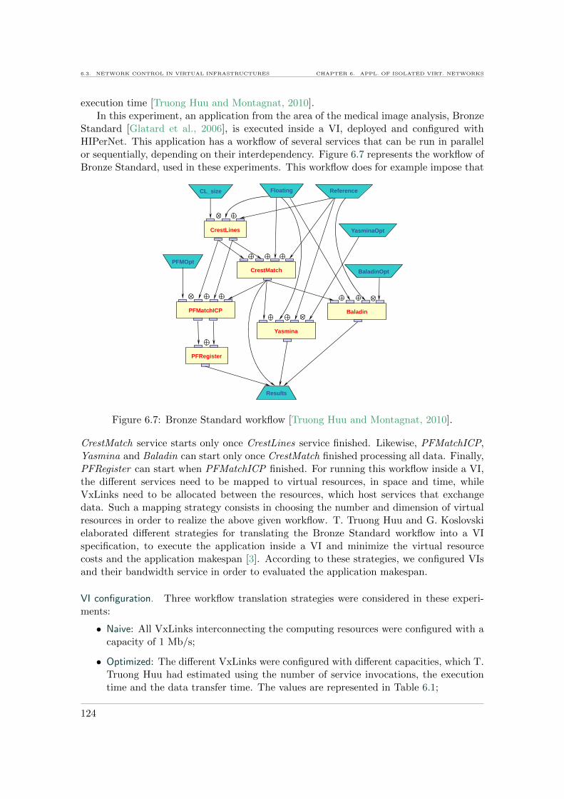
6.3. NETWORK CONTROL IN VIRTUAL INFRASTRUCTURES CHAPTER 6. APPL. OF ISOLATED VIRT. NETWORKS
execution time [Truong Huu and Montagnat, 2010].In this experiment, an application from the area of the medical image analysis, Bronze
Standard [Glatard et al., 2006], is executed inside a VI, deployed and configured withHIPerNet. This application has a workflow of several services that can be run in parallelor sequentially, depending on their interdependency. Figure 6.7 represents the workflow ofBronze Standard, used in these experiments. This workflow does for example impose that
CrestLines
Floating Reference CL_size
CrestMatch PFMOpt
PFMatchICP
Yasmina
YasminaOpt
Baladin
BaladinOpt
PFRegister
Results
Figure 6.7: Bronze Standard workflow [Truong Huu and Montagnat, 2010].
CrestMatch service starts only once CrestLines service finished. Likewise, PFMatchICP,Yasmina and Baladin can start only once CrestMatch finished processing all data. Finally,PFRegister can start when PFMatchICP finished. For running this workflow inside a VI,the different services need to be mapped to virtual resources, in space and time, whileVxLinks need to be allocated between the resources, which host services that exchangedata. Such a mapping strategy consists in choosing the number and dimension of virtualresources in order to realize the above given workflow. T. Truong Huu and G. Koslovskielaborated different strategies for translating the Bronze Standard workflow into a VIspecification, to execute the application inside a VI and minimize the virtual resourcecosts and the application makespan [3]. According to these strategies, we configured VIsand their bandwidth service in order to evaluated the application makespan.
VI configuration. Three workflow translation strategies were considered in these experi-ments:
• Naive: All VxLinks interconnecting the computing resources were configured with acapacity of 1 Mb/s;
• Optimized: The different VxLinks were configured with different capacities, which T.Truong Huu had estimated using the number of service invocations, the executiontime and the data transfer time. The values are represented in Table 6.1;
124

CHAPTER 6. APPL. OF ISOLATED VIRT. NETWORKS 6.4. CONCLUSION
• High: All VxLinks interconnecting the computing resources were configured with acapacity of 10 Mb/s.
Moreover, in the optimized strategy, the execution is separated into several consecutivecomputation stages. In each stage, the required VxLink bandwidth is different.
For each of these strategies, we configured VIs and provisioned all the VxLinks accord-ing to the values given by the used strategy. VXDL specifications describing the topologyof the virtual resources and their dimensions, were defined for the different stages, and theapplication was executed using the MOTEUR workflow engine [Glatard et al., 2008].
We developed a tool that allowed a VI to move from one stage to another, by dy-namically reconfiguring its topology, its VxRouters, and the capacities of its VxLinks,depending on the given VXDL specification. This allowed us to re-adapt the VI at eachstage to the new application requirements, for the optimized strategy.
6.3.3.2 Results and consequences
All experiments were carried out on the HIPerNet instance running on Grid’5000. 30 vir-tual machines were used for executing the application with the different strategies. Ta-ble 6.1 shows the makespan for each workflow translation strategy and the correspondingVI configuration, during each stage, as well as the execution cost. The execution cost iscalculated as a function of the unitary cost of a computing resources cr and the unitarycost of bandwidth cb. This function is inferred from the cost model presented in [3], whichdetermines the coefficients of cr and cb according to the number of resources and theirperiod of utilization. With increasing capacity of VxLinks, the makespan decreases, and
Bandwidth Stage 1 Stage 2 Stage 3 Makespan Execution coststrategy (s) (s) (s) (min) (×105)Low (1 Mb/s) 222.59 ± 2.51 316.57 ± 40.37 2.91 ± 0.50 34.78 ± 0.67 0.65× cr + 0.31× cb
Optimized 53.8 ± 4.56 171.72 ± 24.66 1.53 ± 0.23 22.93 ± 0.58 0.42× cr + 0.48× cb(VxLink capacity) (4.9 Mb/s) (1.95 Mb/s) (3.87 Mb/s)
High (10 Mb/s) 30.79 ± 3.85 42.68 ± 9.55 1.09 ± 0.18 17.72 ± 0.23 0.33× cr + 1.61× cb
Table 6.1: Bandwidth control mechanism evaluation
also its variation. With the optimized strategy, the overall result is the most interesting.Even if the makespan is around 5 minutes longer than in the ‘High’ strategy, increasingalso the computing resources cost by about 20%, the cost of bandwidth is reduced by 70%,leading to an overall cost improvement, considering same unitary prices for bandwidth andcomputing. These results validate the concept of a controlled network. Consequences onthe link between application execution time and VI provisioning cost could be inferred.
6.4 Conclusion
As of writing, virtual infrastructures are broadly know as Infrastructures as a Service(IaaS) in the Cloud. As one of their current limitations is the network performance, weproposed to combine network virtualization with IT virtualization, to obtain virtual infras-tructures with a controlled virtualized network. These controlled virtualized infrastruc-tures are isolated from one another, not only logically, but also in terms of performance,
125
6.4. CONCLUSION CHAPTER 6. APPL. OF ISOLATED VIRT. NETWORKS
especially of the network. Hence, they present an ideal environment for executing appli-cations, where the network performance is of great importance. In the context of a Cloud,they could also add value by selling the network as an accountable resource deliveringguaranteed services. We proposed to apply such virtual infrastructures to the Grid’5000experimental cloud, in order to carry experiments. In this context, a virtual networkservice was added to HIPerNet; a virtual infrastructure management framework, one in-stance of which runs presently on Grid’5000. Finally, this first implementation of virtualnetwork infrastructures, with controlled virtual link rate, allowed us to demonstrate andvalidate the importance of controlled network virtualization, the sharing mechanisms, andthe need for performance control and isolation. This validation strengthens the need fora virtualized network, providing isolation and flexibility, and dissipating the static natureof the network, and hence ‘de-ossifying’ it.
126

7Conclusions and future work
7.1 Summary and conclusions
The Internet has changed its purpose over the last decades, evolving from a communi-cation facility to a shared pool of resources exposed to users as services. This changecreates new communication patterns, and a need for a fundamental architectural changein networks becomes more and more imminent. Virtualization is viewed as a solutionto make networks, and in particular the Internet, more flexible by abstracting the net-work from its hardware and literally ‘de-materializing’ routers and links. This eases thedeployment of new features in the network, based on new protocols and new forwardingmechanisms, hence stimulating innovation. In this context, the main concerns addressed inthis manuscript are sharing mechanisms, necessary when virtualizing the network, and theresulting performance. Furthermore, it investigated the application of virtualized networkswith controlled performance.
In order to obtain maximum configuration flexibility in a virtual network, includingpacket queuing and scheduling, we set the condition that all network resources should bevirtualized at the data-plane.
As a first step, we analyzed and extensively evaluated the performance of techniquesthat could virtualize the network data-plane. A Linux-based virtual router prototypewas built inside a virtual machine to perform routing and forwarding. We evaluated theperformance of this virtual router when co-located with other virtual routers on the samehost, sharing the hardware. Our results indicate that on the one hand, virtualization insoftware is a promising approach for experimentation, even from the network point of view.The evolution of software virtualization technologies over the last few years improved toenable, as of the writing, close to 100% network throughput on 1 Gb/s network interfaces.This is moreover eased through the increasing power of hardware. On the other hand, highprocessing overhead is associated with networking in virtual machines, due to additionalpacket copies and concurrent resource access. Hence, we concluded that to virtualizehigh-speed production networks, such as the Internet, dedicated switching hardware isrequired.
This need for high performance switching led us to examine the current switchingarchitectures and to design a novel architecture that virtualizes the network at layer 2.This architecture, termed as VxSwitch, is based on a buffered crossbar, and its layer 2resources, such as ports and buffers, can be flexibly shared. In addition, schedulers andqueuing mechanisms are virtualized. Thus, VxSwitch allows to create multiple virtualswitches sharing the same hardware. Each virtual switch can have a configurable numberof ports, capacity per port, buffer sizes, as well as scheduling and queuing mechanisms.The benefit of the high configurability is twofold: through resource dimensioning andsharing, it allows to isolate virtual networks at the lowest level, hence giving them strictperformance guarantees; and the configuration of packet queuing and scheduling allowsusers to finely tune QoS with custom algorithms.
Furthermore, we investigated the application of virtual routers and the sharing of
127
7.1. SUMMARY AND CONCLUSIONS CHAPTER 7. CONCLUSIONS AND FUTURE WORK
physical networks into isolated virtual networks. A virtual network service, combiningprogrammable virtual routers with dimensionable virtual links was proposed, to deliverconfigurable and guaranteed service levels to end users of virtual networks. For realizingthis service, different technologies were explored to set up virtual routers and virtual linkswith controlled bandwidth. One approach consisted in implementing the service usingthe previously built prototype of a virtual software router. As an interesting alternative,delivering better performance and high configurability, we investigated the OpenFlowtechnology and proposed a realization of virtual routers on top of OpenFlow switches.These gather configurability and performance in a unique way, enabling the virtualizationof the forwarding logic.
We validated the concept of isolated virtual networks by applying it to virtual infras-tructures. As discussed beforehand, virtual infrastructures, have been promoted by Cloudsand consist in sets of virtual computing and storage nodes made available as a service over acertain period of time. The interconnection network plays a key role in the communicationperformance achieved by virtual nodes. However, the network is not integrated as a serviceof the Cloud. To provide virtual infrastructures with performance guarantees, we proposedto combine IT (computing and storage) virtualization with network virtualization. Thisallowed us to build virtual infrastructures that share the network in a controlled way, andthat are isolated from each other in terms of performance. This concept was implementedin the Grid’5000 testbed, as an automatic virtual network management software module.It was validated through experimentation with large scale distributed applications.
Finally, we answer the questions raised in Chapter 1.
[Q1] How does virtualization impact network communication performance?
— The additional layer introduced by virtualization causes additional processingwhile forwarding packets between NICs and virtual network devices. For virtualrouters implemented in software, additional packet copies between NICs andvirtual machines cause such processing overhead. Yet, with modern hardwareand powerful CPUs, close to 1 Gb/s throughput can be obtained on softwarevirtual routers for big packets, at a CPU cost which is several times higher thanon a classical software router.
[Q2] Where and how can virtualization be implemented in the network, in order to reducethe performance impact while enabling configurability?
— For enabling maximum configurability, virtualization needs to be implementedat the data plane, so that each virtual network has the ability to forward,filter, shape, etc., its traffic. Nevertheless, due to the performance overheadintroduced by virtualization in software, it is necessary to virtualize the dataplane of routers in hardware, i.e., the switching fabric.
[Q3] When virtualizing a network, which are the resources that need to be shared?
— The resources of a network that are relevant to performance and QoS are es-sentially link capacity and buffer size. Hence, an efficient approach to providevirtual networks with performance guarantees and QoS is virtualize these, so
128

CHAPTER 7. CONCLUSIONS AND FUTURE WORK 7.2. PERSPECTIVES FOR FUTURE WORK
that each virtual network benefits from virtual links with configurable capacity,and virtual buffers with configurable sizes. This can be achieved with VxSwitch.
[Q4] How to provide deterministic performance and QoS to virtual networks?
— It is the sharing of the link capacity, which is crucial to provide a virtualnetwork with deterministic performance. Hence, it is necessary to configurevirtual links, and thus the ports of virtual network devices, with bandwidth.For ensuring that each virtual network device obtains the configured bandwidth,their access to the hardware must be scheduled accordingly. For providing QoSand different service levels inside each virtual network, we advocate to virtualizethe switching fabric of network devices, and to enable each virtual networkdevice to be configured with different virtual buffer sizes and different packetscheduling algorithms, as proposed in VxSwitch.
[Q5] What are the applications of controlled virtual networks?
— Thanks to their de-materialization, virtual networks can be deployed on de-mand when needed. Hence, they can be deployed to interconnect computingand storage nodes of a temporary virtual infrastructure, and provide it withdeterministic network performance. This makes the execution time of applica-tions running inside the virtual infrastructure predictable. Such performanceguarantees can be especially useful in the context of Clouds, where virtual in-frastructures have a business value and are leased as a service. Virtual networks,when controlled, can also be leased as a service with different performance lev-els.
7.2 Perspectives for future work
The presented work investigated the performance and the sharing mechanisms for virtual-ized networks. While research and industry now turned towards networkvirtualization—e.g., research resulted in multiple virtual network testbeds, manufacturerspropose virtualized routers for consolidation—large-scale virtualized production networksare still a step away from reality. This is, in our opinion, related to performance andconfiguration issues. Therefore, we advocate that virtualization must move to the lowestlevel in the networks, the closest possible to the hardware. We expect a lot of researchin this direction. To select a few possible subjects, related with our work, we retain thefollowing.
Scheduling and queuing strategies for VxSwitch. We believe VxSwitch is an approach totake when virtualizing the network hardware. Its high configurability in terms of resourcedimensioning and scheduling enables multiple new types of configuration. Resource shar-ing and QoS can be programmed and realized in many ways. Hence, VxSwitch is a supportfor innovation, and we plan to investigate new algorithms for differentiated resource shar-ing between virtual switches. There are many possibilities between strict sharing andvariable sharing. In particular, the best tradeoff between guarantees and resource uti-lization must be found, depending on the context. The resource sharing and scheduling
129

7.2. PERSPECTIVES FOR FUTURE WORK CHAPTER 7. CONCLUSIONS AND FUTURE WORK
between all virtual switches and inside each virtual switch should for example be analyzedmore specifically. One of our next goals is to implement a first prototype of VxSwitch, forexample on FPGA.
Combining VxSwitch with OpenFlow. One very promising solution for programming, andeven virtualizing switches is OpenFlow. However, currently it only enables the virtualiza-tion of the forwarding logic, meaning the forwarding decisions, through the programmingof the flowtable. We plan to combine OpenFlow with VxSwitch, as we think it could bea compelling approach to provide customized routing and forwarding on a per flow-level,where each flow obtains specific QoS. For example, by mapping OpenFlow instances tovirtual switches, a flow could be mapped directly to a virtual buffer of a virtual switch.Output scheduling could be adapted to provide specific flow-level service guarantees.
Virtualization in the optical network. Optical fiber is the present technology in the Internetbackbone. It moves closer and closer to the edges with technologies such as Fiber to thehome. Hence, one of our next goals is to examine the optical network components forvirtualization. Optical fiber starts providing 100 Gb/s connectivity. Thus, it is appealingto virtualize links into smaller virtual channels. Together with this, virtualizing cross-connects could allow to establish different circuits with those virtual channels, and organizethem into different virtual networks. We are currently investigating on the virtualizationof the optical network combined with IT virtualization within the Geysers [GEY] project.
130
PublicationsInternational Journals & Book chapter
[1] Fabienne Anhalt, Guilherme Koslovski, and Pascale Vicat-Blanc Primet. Specifying and provisioningvirtual infrastructures with HIPerNet. ACM International Journal of Network Management (IJNM) -special issue on Network Virtualization and its Management, 20:129–148, May 2010.
[2] Fabienne Anhalt and Pascale Vicat-Blanc Primet. Analysis and experimental evaluation of networkdata-plane virtualization mechanisms. International Journal On Advances in Intelligent Systems, 2009.
[3] Tram Truong Huu, Guilherme Koslovski, Fabienne Anhalt, Johan Montagnat, and Pascale Vicat-Blanc Primet. Joint elastic cloud and virtual network framework for application performance-costoptimization. Journal of Grid Computing, 9:27–47, 2011. 10.1007/s10723-010-9168-6.
[4] Pascale Vicat-Blanc, Sergi Figuerola, Xiaomin Chen, Giada Landi, Eduard Escalona, Chris Develder,Anna Tzanakaki, Yuri Demchenko, Joan A. Garcıa Espın, Jordi Ferrer, Ester Lopez, Sebastien Soudan,Jens Buysse, Admela Jukan, Nicola Ciulli, Marc Brogle, Luuk van Laarhoven, Bartosz Belter, FabienneAnhalt, Reza Nejabati, Dimitra Simeonidou, Canh Ngo, Cees de Laat, Matteo Biancani, Michael Roth,Pasquale Donadio, Javier Jimenez, Monika Antoniak-Lewandowska, and Ashwin Gumaste. BringingOptical Networks to the Cloud: an Architecture for a Sustainable future Internet, Chapter in FIAbook. Springer Lecture Notes, May 2011.
Conferences with Proceedings
[5] Fabienne Anhalt, Dinil Mon Divakaran, and Pascale Vicat-Blanc Primet. A virtual switch architecturefor hosting virtual networks on the Internet. In 11th International Conference on High PerformanceSwitching and Routing (IEEE HPSR), Dallas, Texas, USA, 6 2010.
[6] Pascale Vicat-Blanc Primet, Fabienne Anhalt, and Guilherme Koslovski. Exploring the virtual infras-tructure service concept in Grid’5000. In 20th ITC Specialist Seminar on Network Virtualization, HoiAn, Vietnam, May 2009.
[7] Fabienne Anhalt and Pascale Vicat-Blanc Primet. Analysis and experimental evaluation of data planevirtualization with Xen. In ICNS 09 : International Conference on Networking and Services, Valencia,Spain, April 2009. Top paper award.
[8] Dinil Mon Divakaran, Fabienne Anhalt, Eitan Altman, and Pascale Vicat-Blanc Primet. Size-Basedflow scheduling in a CICQ switch. In 11th International Conference on High Performance Switchingand Routing (IEEE HPSR 2010), Dallas, Texas, USA, June 2010. Accepted for publication.
[9] Lucas Nussbaum, Fabienne Anhalt, Olivier Mornard, and Jean-Patrick Gelas. Linux-based virtualiza-tion for HPC clusters. In Linux Symposium 2009, July 2009.
[10] Fabienne Anhalt, Guilherme Koslovski, Marcelo Pasin, Jean-Patrick Gelas, and Pascale Vicat-BlancPrimet. Les Infrastructures Virtuelles a la demande pour un usage flexible de l’Internet. In JDIR 09:Journees Doctorales en Informatique et Reseaux, Belfort, France, February 2009.
Research Reports
[11] Anhalt, F., Vicat-Blanc Primet, P.: Analysis and evaluation of a XEN based virtual router. TechnicalReport 6658, INRIA Rhone Alpes (Sep 2008)
[12] Vicat-Blanc Primet, P., Koslovski, G., Anhalt, F., Truong Huu, T., Montagnat, J.: Exploring theVirtual Infrastructure as a Service concept with HIPerNet. Research Report RR-7185, INRIA (2010)
[13] Anhalt, F., Blanchet, C., Guillier, R., Truong Huu, T., Koslovski, G., Montagnat, J., Vicat- BlancPrimet, P., Roca, V.: HIPCAL: final report. Research Report, INRIA (2010)
131

SOFTWARE
[14] Garcıa-Espin, J.A., Ferrer Riera, J., Lopez, E., Figuerola, S., Donadio, P., Buffa, G., Peng, S.,Escalona, E., Soudan, S., Anhalt, F., Robinson, P., Antonescu, A.F., Tzanakaki, A., Anastasopoulos,M., Tovar, A., Jimenez, J., Chen, X., Ngo, C., Ghijsen, M., Demchemko, Y., Landi, G., Lopatowski,L., Gutkowski, J., Belter, B.: Deliverable D3.1: Functional Description of the Logical InfrastructureComposition Layer (LICL). Research Report, ICT-2009.1.1 (2010)
Miscellaneous
[15] Anhalt, F., Guillier, R., Koslovski, G. and Vicat-Blanc Primet, P. HIPerNet: virtual infrastructuremanipulation. Practical Session in Grid’5000 Spring School (April 2010, Lille, France).
[16] Anhalt, F., Guillier, Mornard, O. and Vicat-Blanc Primet, P. HIPerNET network performance iso-lation techniques for confined virtual infrastructures. Presentation in Grid’5000 Spring School (April2009, Nancy, France).
[17] Vicat-Blanc Primet, P., Koslovski, G., Anhalt, F.: Hipcal: Combined network and system virtualiza-tion (January 2010) Colloque STIC de l’Agence Nationale de la Recherche (ANR), Paris, France.
[18] Anhalt, F., Gelas, J.P., Vicat-Blanc Primet, P.: Exploration of router performance with data-planevirtualization (June 2009) Poster in Rescom 2009 Summer School, La Palmyre, France.
Patent
[VxSwitch] Anhalt, F and Vicat-Blanc Primet, P. VXSwitch Patent - INPI: No 10/00368, 2010. LYaTiss,INRIA ENS Lyon - Available: http://www.lyatiss.com
Software
[HIPerNet] Vicat-Blanc Primet, P. and Koslovski, G. and Anhalt, F. and Soudan, S. andGuillier, R. and Martinez, P. and Mornard, O. and Gelas, J.-P. HIPerNet APPcode:IDDN.FR.001.260010.000.S.P.2009.000.10700, 2009, LYaTiss, INRIA ENS Lyon - Available: http:
//www.lyatiss.com
132

ReferencesOnline References
[4WA] The FP7 4WARD Project. Available: http://www.4ward-project.eu/.
[AMA] Amazon web services. Available: http://aws.amazon.com/.
[AZU] Windows Azure. Available: http://www.microsoft.com/windowsazure/.
[CLI] The Click Modular Router Project. Available: http://read.cs.ucla.edu/click/click/.
[EUC] Eucalyptus. Available: http://www.eucalyptus.com/.
[FI] What is FIA?: Future Internet. Available: http://www.future-internet.eu/.
[G5K] Aladdin/Grid’5000. Available: http://www.grid5000.fr/.
[GEN] The Global Environment for Network Innovations (GENI). Available: http://www.geni.net/.
[GEY] Generalized Architecture for Dynamic Infrastructure Services. Available: http://www.geysers.
eu/.
[HYV] Hyper-V Server. Available: http://www.microsoft.com/hyper-v-server/.
[IEE] IEEE - Advancing Technology for Humanity. Available: http://www.ieee.org/.
[IOVa] PCI: Linux kernel SR-IOV support. Available: http://lwn.net/Articles/324612/.
[IOVb] PCI-SIG I/O Virtualization (IOV) Specifications. Available: http://www.pcisig.com/
specifications/iov/.
[IPE] Iperf. Available: http://iperf.sourceforge.net/.
[JAI] FreeBSD Jails. Available: http://www.freebsd.org/doc/handbook/jails.html/.
[MYR] Myricom. Available: http://www.myri.com/.
[NEB] OpenNebula. Available: http://opennebula.org/.
[NET] Neterion. Available: http://neterion.com/.
[NFP] NetFPGA. Available: http://www.netfpga.org/.
[NPE] NetPerf. Available: http://www.netperf.org/netperf/.
[OCC] OGF Occi. Available: http://occi-wg.org/.
[OF] The OpenFlow Switch Consortium. Available: http://www.openflowswitch.org/.
[OVS] Open vSwitch. Available: http://openvswitch.org/.
[OVZ] OpenVZ Wiki. Available: http://wiki.openvz.org/.
[QEM] Qemu. Available: http://wiki.qemu.org/.
[REN] Le Reseau National de telecommunications pour la Technologie l’Enseignement et la Recherche.
[SAI] Scalable and Adaptive Internet Solutions project (FP7 SAIL). Available: http://www.
sail-project.eu/.
[TC] Traffic Control. Available: http://lartc.org/.
[TUN] Universal TUN/TAP driver. Available: http://vtun.sourceforge.net/tun/.
[UML] The User-mode Linux Kernel. Available: http://user-mode-linux.sourceforge.net/.
[VBX] VirtualBox. Available: http://www.virtualbox.org/.
[VIN] VINI A Virtual Network Infrastructure. Available: http://www.vini-veritas.net/.
[VMW] VMware. Available: http://www.vmware.com/.
[VRZ] Parallels Virtuozzo. Available: http://www.parallels.com/fr/products/pvc46/.
[VSP] VMware vSphere. Available: http://www.vmware.com/products/vsphere/.
[VSR] Linux-VServer. Available: http://linux-vserver.org/.
[VXD] VXDL: Virtual private eXecution infrastructure Description Language. Available: http://www.
ens-lyon.fr/LIP/RESO/Software/vxdl/home.html.
[XCS] Xen Credit Scheduler. Available: http://wiki.xensource.com/xenwiki/CreditScheduler/.
133

REFERENCES
References
[RES, 2008] (2008). RESERVOIR - An ICT Infrastructure for Reliable and Effective Delivery of Servicesas Utilities. Technical Report H-0262, IBM Research Division.
[HVR, 2008] (2008). Router Virtualization in Service Providers. Technical report, Cisco Systems.
[CSD, 2008] (2008). The Cisco Application eXtension Platform: Doing More with Less. Intel Systems.
[JCS, 2009] (2009). Control plane scaling and router virtualization. Technical Report 2000261-001-EN,Juniper Networks.
[OF1, 2009] (2009). OpenFlow Switch Specification Version 1.0.0 (Wire Protocol 0x01). .
[vDS, 2009] (2009). What’s New in VMware vSphere 4: Virtual Networking. WMware Inc. White Paper.
[VCS, 2010] (2010). Introducing Brocade Virtual Cluster Switching. Brocade Communications Systems.http://www.brocade.com/downloads/documents/white_papers/Introducing_Brocade_VCS_WP.pdf.
[NEX, 2010] (2010). Virtual Machine Networking: Standards and Solutions. Cisco.
[Andersen et al., 2001] Andersen, D., Balakrishnan, H., Kaashoek, F., and Morris, R. (2001). ResilientOverlay Networks. pages 131–145.
[Anderson et al., 2005] Anderson, T., Peterson, L., Shenker, S., and Turner, J. (2005). Overcoming theInternet Impasse through Virtualization. Computer, 38(4).
[Anwer and Feamster, 2009] Anwer, M. B. and Feamster, N. (2009). Building a fast, virtualized data planewith programmable hardware. In Proceedings of the 1st ACM workshop on Virtualized infrastructuresystems and architectures, VISA ’09, pages 1–8, New York, NY, USA. ACM.
[Anwer et al., 2010] Anwer, M. B., Motiwala, M., Tariq, M. b., and Feamster, N. (2010). SwitchBlade: aplatform for rapid deployment of network protocols on programmable hardware. SIGCOMM Comput.Commun. Rev., 40:183–194.
[Appenzeller et al., 2004] Appenzeller, G., Keslassy, I., and McKeown, N. (2004). Sizing router buffers.SIGCOMM Comput. Commun. Rev., 34:281–292.
[Argyraki et al., 2008] Argyraki, K., Baset, S., Chun, B.-G., Fall, K., Iannaccone, G., Knies, A., Kohler,E., Manesh, M., Nedevschi, S., and Ratnasamy, S. (2008). Can software routers scale? In Proceedings ofthe ACM workshop on Programmable routers for extensible services of tomorrow, PRESTO ’08, pages21–26, New York, NY, USA. ACM.
[Barham et al., 2003] Barham, P., Dragovic, B., Fraser, K., Hand, S., Harris, T., Ho, A., Neugebauer,R., Pratt, I., and Warfield, A. (2003). Xen and the art of virtualization. In SOSP ’03: Proceedings ofthe nineteenth ACM symposium on Operating systems principles, pages 164–177, New York, NY, USA.ACM.
[Barre et al., 2010] Barre, S., Bonaventure, O., Raiciu, C., and Handley, M. (2010). Experimenting withmultipath TCP. SIGCOMM Comput. Commun. Rev., 40:443–444.
[Baumgartner et al., 2002] Baumgartner, F., Braun, T., and Bhargava, B. K. (2002). Virtual Routers: ATool for Emulating IP Routers. In LCN’02, pages 363–371.
[Baumgartner et al., 2003] Baumgartner, F., Braun, T., Kurt, E., and Weyland, A. (2003). Virtual routers:a tool for networking research and education. SIGCOMM Comput. Commun. Rev., 33:127–135.
[Bavier et al., 2004] Bavier, A., Bowman, M., Chun, B., Culler, D., Karlin, S., Muir, S., Peterson, L.,Roscoe, T., Spalink, T., and Wawrzoniak, M. (2004). Operating system support for planetary-scalenetwork services. In NSDI’04: Proceedings of the 1st conference on Symposium on Networked SystemsDesign and Implementation, pages 19–19, Berkeley, CA, USA. USENIX Association.
[Bavier et al., 2006] Bavier, A., Feamster, N., Huang, M., Peterson, L., and Rexford, J. (2006). In VINIveritas: realistic and controlled network experimentation. SIGCOMM Comput. Commun. Rev., 36:3–14.
[Bellard, 2005] Bellard, F. (2005). QEMU, a fast and portable dynamic translator. In ATEC ’05: Pro-ceedings of the annual conference on USENIX Annual Technical Conference, pages 41–41, Berkeley, CA,USA. USENIX Association.
134
REFERENCES
[Bhatia et al., 2008] Bhatia, S., Motiwala, M., Muhlbauer, W., Mundada, Y., Valancius, V., Bavier, A.,Feamster, N., Peterson, L., and Rexford, J. (2008). Trellis: a platform for building flexible, fast virtualnetworks on commodity hardware. In Proceedings of the 2008 ACM CoNEXT Conference, CoNEXT’08, pages 72:1–72:6, New York, NY, USA. ACM.
[Bin Tariq et al., 2009] Bin Tariq, M., Mansy, A., Feamster, N., and Ammar, M. (2009). CharacterizingVLAN-induced sharing in a campus network. In Proceedings of the 9th ACM SIGCOMM conference onInternet measurement conference, IMC ’09, pages 116–121, New York, NY, USA. ACM.
[Brehon et al., 2007] Brehon, Y., Kofman, D., and Casaca, A. (2007). Virtual Private Network to Span-ning Tree Mapping. In Akyildiz, I., Sivakumar, R., Ekici, E., Oliveira, J., and McNair, J., editors,NETWORKING 2007. Ad Hoc and Sensor Networks, Wireless Networks, Next Generation Internet,volume 4479 of Lecture Notes in Computer Science, pages 703–713. Springer Berlin / Heidelberg.
[Busson et al., 2007] Busson, A., Kofman, D., and Rougier, J.-L. (2007). A new service overlays dimen-sioning approach based on stochastic geometry. Perform. Eval., 64:76–92.
[Caesar and Rexford, 2008] Caesar, M. and Rexford, J. (2008). Building bug-tolerant routers with virtu-alization. In PRESTO ’08, pages 51–56. ACM.
[Cappello et al., 2005] Cappello, F., Caron, E., Dayde, M., Desprez, F., Jegou, Y., Primet, P., Jeannot,E., Lanteri, S., Leduc, J., Melab, N., Mornet, G., Namyst, R., Quetier, B., and Richard, O. (2005).Grid’5000: a large scale and highly reconfigurable grid experimental testbed. In Grid Computing, 2005.The 6th IEEE/ACM International Workshop on, pages 8 pp.+.
[Chen et al., 2009] Chen, X., Mao, Z. M., and Van Der Merwe, J. (2009). ShadowNet: a platform forrapid and safe network evolution. In Proceedings of the 2009 conference on USENIX Annual technicalconference, USENIX’09, pages 3–3, Berkeley, CA, USA. USENIX Association.
[Chisnall, 2007] Chisnall, D. (2007). The Definitive Guide to the Xen Hypervisor. Prentice Hall.
[Chowdhury and Boutaba, 2009] Chowdhury, N. M. M. K. and Boutaba, R. (2009). Network virtualiza-tion: state of the art and research challenges. Comm. Mag., 47:20–26.
[Congdon et al., 2010] Congdon, P., Fischer, A., and Mohapatra, P. (2010). A Case for VEPA: VirtualEthernet Port Aggregator. In ITC 22.
[Das et al., 2010] Das, S., Parulkar, G., Singh, P., Getachew, D., Ong, L., and McKeown, N. (2010).Packet and Circuit Network Convergence with OpenFlow.
[De Carli et al., 2009] De Carli, L., Pan, Y., Kumar, A., Estan, C., and Sankaralingam, K. (2009). PLUG:flexible lookup modules for rapid deployment of new protocols in high-speed routers. In SIGCOMM ’09.ACM.
[Dike, 2001] Dike, J. (2001). User-mode Linux. In Proceedings of the 5th annual Linux Showcase &Conference - Volume 5, pages 2–2, Berkeley, CA, USA. USENIX Association.
[Divakaran et al., 2009] Divakaran, D. M., Soudan, S., Vicat-Blanc Primet, P., and Altman, E. (2009). Asurvey on core switch designs and algorithms. Research Report RR-6942, INRIA.
[Divakaran and Vicat-Blanc Primet, 2007] Divakaran, D. M. and Vicat-Blanc Primet, P. (2007). ChannelProvisioning in Grid Overlay Networks (short paper). In Workshop on IP QoS and Traffic Control.
[Dobrescu et al., 2009] Dobrescu, M., Egi, N., Argyraki, K., Chun, B.-G., Fall, K., Iannaccone, G., Knies,A., Manesh, M., and Ratnasamy, S. (2009). RouteBricks: exploiting parallelism to scale software routers.In SOSP ’09: Proc. of the ACM SIGOPS 22nd symposium on Operating systems principles. ACM.
[Dong et al., 2008] Dong, Y., Yu, Z., and Rose, G. (2008). SR-IOV networking in Xen: architecture,design and implementation. In Proceedings of the First conference on I/O virtualization, WIOV’08,pages 10–10, Berkeley, CA, USA. USENIX Association.
[Duffield et al., 1999] Duffield, N. G., Goyal, P., Greenberg, A., Mishra, P., Ramakrishnan, K. K., andvan der Merive, J. E. (1999). A flexible model for resource management in virtual private networks. InSIGCOMM ’99: Proceedings of the conference on Applications, technologies, architectures, and protocolsfor computer communication, pages 95–108, New York, NY, USA. ACM.
[Egi et al., 2008a] Egi, N., Greenhalgh, A., Handley, M., Hoerdt, M., Huici, F., and Mathy, L. (2008a).Fairness issues in software virtual routers. In PRESTO ’08, pages 33–38. ACM.
135
REFERENCES
[Egi et al., 2008b] Egi, N., Greenhalgh, A., Handley, M., Hoerdt, M., Huici, F., and Mathy, L. (2008b).Towards high performance virtual routers on commodity hardware. In Proceedings of the 2008 ACMCoNEXT Conference, CoNEXT ’08, pages 20:1–20:12, New York, NY, USA. ACM.
[Egi et al., 2009] Egi, N., Greenhalgh, A., Hoerdt, M., Huici, F., Papadimitriou, P., Handley, M., andMathy, L. (2009). A Platform for High Performance and Flexible Virtual Routers on CommodityHardware. SIGCOMM 2009 poster session.
[Feamster et al., 2007] Feamster, N., Gao, L., and Rexford, J. (2007). How to lease the internet in yourspare time. SIGCOMM CCR, 37(1).
[Feldmann, 2007] Feldmann, A. (2007). Internet clean-slate design: what and why? SIGCOMM Comput.Commun. Rev., 37:59–64.
[Floyd and Jacobson, 1993] Floyd, S. and Jacobson, V. (1993). Random early detection gateways forcongestion avoidance. IEEE/ACM Trans. Netw., 1:397–413.
[Fu and Rexford, 2008] Fu, J. and Rexford, J. (2008). Efficient IP-address lookup with a shared forwardingtable for multiple virtual routers. In Proceedings of the 2008 ACM CoNEXT Conference, CoNEXT ’08,pages 21:1–21:12, New York, NY, USA. ACM.
[Glatard et al., 2008] Glatard, T., Montagnat, J., Lingrand, D., and Pennec, X. (2008). Flexible andefficient workflow deployement of data-intensive applications on grids with MOTEUR. Int. Journal ofHigh Performance Computing and Applications (IJHPCA), 22(3):347–360.
[Glatard et al., 2006] Glatard, T., Pennec, X., and Montagnat, J. (2006). Performance evaluation of grid-enabled registration algorithms using bronze-standards. In Medical Image Computing and Computer-Assisted Intervention(MICCAI’06), LNCS 4191, pages 152–160, Copenhagen, Denmark. Springer.
[Greenberg et al., 2005] Greenberg, A., Hjalmtysson, G., Maltz, D. A., Myers, A., Rexford, J., Xie, G.,Yan, H., Zhan, J., and Zhang, H. (2005). A clean slate 4D approach to network control and management.SIGCOMM Comput. Commun. Rev., 35:41–54.
[Gude et al., 2008] Gude, N., Koponen, T., Pettit, J., Pfaff, B., Casado, M., McKeown, N., and Shenker,S. (2008). NOX: towards an operating system for networks. SIGCOMM Comput. Commun. Rev.,38(3):105–110.
[Handley, 2006] Handley, M. (2006). Why the Internet only just works. BT Technology Journal, 24(3):119–129.
[Handley et al., 2005] Handley, M., Kohler, E., Ghosh, A., Hodson, O., and Radoslavov, P. (2005). De-signing extensible IP router software. In Proceedings of the 2nd conference on Symposium on NetworkedSystems Design & Implementation - Volume 2, NSDI’05, pages 189–202, Berkeley, CA, USA. USENIXAssociation.
[Hassayoun and Ros, 2009] Hassayoun, S. and Ros, D. (2009). Loss synchronization, router buffer sizingand high-speed TCP versions: Adding RED to the mix. In Local Computer Networks, 2009. LCN 2009.IEEE 34th Conference on, pages 569 –576.
[Hibler et al., 2008] Hibler, M., Ricci, R., Stoller, L., Duerig, J., Guruprasad, S., Stack, T., Webb, K., andLepreau, J. (2008). Large-scale virtualization in the Emulab network testbed. In USENIX 2008 AnnualTechnical Conference on Annual Technical Conference, pages 113–128, Berkeley, CA, USA. USENIXAssociation.
[IaaS, 2008] IaaS (2008). Evaluation of current network control and management plane for multi-domainnetwork infrastructure. FEDERICA Deliverable DJRA1.1.
[Iyer and McKeown, 2001] Iyer, S. and McKeown, N. (2001). Techniques for Fast Shared MemorySwitches. Technical Report TR01-HPNG-081501, Stanford University HPNG.
[Jain et al., 1984] Jain, R. K., Chiu, D.-M. W., and Hawe, W. R. (1984). A Quantitative Measure ofFairness and Discrimination for Resource Allocation in Shared Computer Systems. ACM Transactionon Computer Systems.
[Kamp and Watson, 2000] Kamp, P.-H. and Watson, R. N. M. (2000). Jails: Confining the omnipotentroot. In In Proc. 2nd Intl. SANE Conference.
[Kanizo et al., 2009] Kanizo, Y., Hay, D., and Keslassy, I. (2009). The Crosspoint-Queued Switch. InIEEE INFOCOM 2009.
136
REFERENCES
[Keller and Rexford, 2010] Keller, E. and Rexford, J. (2010). The ”Platform as a Service” Model forNetworking. In INM/WREN ’10.
[Keller et al., 2009] Keller, E., Yu, M., Caesar, M., and Rexford, J. (2009). Virtually eliminating routerbugs. In Proceedings of the 5th international conference on Emerging networking experiments and tech-nologies, CoNEXT ’09, pages 13–24, New York, NY, USA. ACM.
[Kelly et al., 2010] Kelly, J., Araujo, W., and Banerjee, K. (2010). Rapid service creation using the JUNOSSDK. SIGCOMM Comput. Commun. Rev., 40:56–60.
[Kim et al., 2010] Kim, W., Sharma, P., Lee, J., Banerjee, S., Tourrilhes, J., Lee, S.-J., and Yalagandula,P. (2010). Automated and scalable QoS control for network convergence. In Proceedings of the 2010INM/WREN. USENIX Association.
[Kivity et al., 2007] Kivity, A., Kamay, Y., Laor, D., Lublin, U., and Liguori, A. (2007). kvm: the LinuxVirtual Machine Monitor. In Linux Symposium.
[Kodama et al., 2004] Kodama, Y., Kudoh, T., Takano, R., Sato, H., Tatebe, O., and Sekiguchi, S. (2004).GNET-1: gigabit Ethernet network testbed. Cluster Computing, IEEE International Conference on,0:185–192.
[Koh et al., 2006] Koh, Y., Pu, C., Bhatia, S., and Consel, C. (2006). Efficient Packet Processing in User-Level OSes: A Study of UML. In Local Computer Networks, Proceedings 2006 31st IEEE Conferenceon, pages 63 –70.
[Kolon, 2004] Kolon, M. (2004). Intelligent Logical Router Service. Technical Report 200097-001, JuniperNetworks.
[Koslovski et al., 2011] Koslovski, G., Soudan, S., Goncalves, P., and Vicat-Blanc, P. (2011). LocatingVirtual Infrastructures: Users and InP Perspectives. In 12th IEEE/IFIP International Symposium onIntegrated Network Management - Special Track on Management of Cloud Services and Infrastructures(IM 2011 - STMCSI), Dublin, Ireland. IEEE.
[Koslovski et al., 2009] Koslovski, G., Truong Huu, T., Montagnat, J., and Vicat-Blanc Primet, P. (2009).Executing distributed applications on virtualized infrastructures specified with the VXDL languageand managed by the HIPerNET framework. In First International Conference on Cloud Computing(CLOUDCOMP 2009), Munich, Germany.
[Koslovski et al., 2008] Koslovski, G., Vicat-Blanc Primet, P., and Charao, A. S. (2008). VXDL: VirtualResources and Interconnection Networks Description Language. In GridNets 2008.
[Laganier and Vicat-Blanc Primet, 2005] Laganier, J. and Vicat-Blanc Primet, P. (2005). HIPernet: ADecentralized Security Infrastructure for Large Scale Grid Environments. In Proceedings of the 6thIEEE/ACM International Workshop on Grid Computing, GRID ’05, pages 140–147, Washington, DC,USA. IEEE Computer Society.
[Laor, 2007] Laor, D. (2007). KVM Para-Virtualized Guest Drivers. KVM Forum 2007.
[Lee et al., 2010] Lee, D., Carpenter, B. E., and Brownlee, N. (2010). Observations of UDP to TCP Ratioand Port Numbers. In Proceedings of the 2010 Fifth International Conference on Internet Monitoringand Protection, ICIMP ’10, pages 99–104, Washington, DC, USA. IEEE Computer Society.
[Lee et al., 2008] Lee, S.-J., Banerjee, S., Sharma, P., Yalagandula, P., and Basu, S. (2008). Bandwidth-Aware Routing in Overlay Networks. In Proceedings of IEEE INFOCOM, Phoenix, AZ.
[Liao et al., 2009] Liao, Y., Yin, D., and Gao, L. (2009). PdP: parallelizing data plane in virtual net-work substrate. In Proceedings of the 1st ACM workshop on Virtualized infrastructure systems andarchitectures, VISA ’09, pages 9–18, New York, NY, USA. ACM.
[Liao et al., 2010] Liao, Y., Yin, D., and Gao, L. (2010). Europa: Efficietn User Mode Packet Forwardingin Network Virtualization. In Proceedings of the 2010 INM/WREN. USENIX Association.
[Louati et al., 2009] Louati, W., Houidi, I., and Zeghlache, D. (2009). Autonomic Virtual Routers for theFuture Internet. In Nunzi, G., Scoglio, C., and Li, X., editors, IP Operations and Management, volume5843 of Lecture Notes in Computer Science, pages 104–115. Springer Berlin / Heidelberg. 10.1007/978-3-642-04968-2 9.
[Lu et al., 2009] Lu, G., Shi, Y., Guo, C., and Zhang, Y. (2009). CAFE: a configurable packet forwardingengine for data center networks. In Proceedings of the 2nd ACM SIGCOMM workshop on Programmablerouters for extensible services of tomorrow, PRESTO ’09, pages 25–30, New York, NY, USA. ACM.
137

REFERENCES
[McIlroy and Sventek, 2006] McIlroy, R. and Sventek, J. (2006). Resource Virtualisation of NetworkRouters. In HPSR 06: 2006 Workshop on High Performance Switching and Routing.
[McKeown et al., 2008] McKeown, N., Anderson, T., Balakrishnan, H., Parulkar, G., Peterson, L., Rex-ford, J., Shenker, S., and Turner, J. (2008). OpenFlow: enabling innovation in campus networks.SIGCOMM CCR, 38(2):69–74.
[Mell and Grance, 2009] Mell, P. and Grance, T. (2009). The NIST Definition of Cloud Computing.
[Melle et al., 2008] Melle, S., Dodd, R., Grubb, S., Liou, C., Vusirikala, V., and Welch, D. (2008). Band-width virtualization enables long-haul WDM transport of 40 Gb/s and 100 Gb/s services. Communica-tions Magazine, IEEE, 46(2):S22 –S29.
[Menon et al., 2006] Menon, A., Cox, A. L., and Zwaenepoel, W. (2006). Optimizing network virtualiza-tion in Xen. In ATEC ’06: Proceedings of the annual conference on USENIX ’06 Annual TechnicalConference, pages 2–2. USENIX Association.
[Mhamdi et al., 2006] Mhamdi, L., Kachris, C., and Vassiliadis, S. (2006). A reconfigurable hardwarebased embedded scheduler for buffered crossbar switches. In Proceedings of the 2006 ACM/SIGDA 14thinternational symposium on Field programmable gate arrays, FPGA ’06, pages 143–149, New York, NY,USA. ACM.
[Mogul et al., 2008] Mogul, J. C., Yalagandula, P., Tourrilhes, J., McGeer, R., Banerjee, S., Connors, T.,and Sharma, P. (2008). API Design Challenges for Open Router Platforms on Proprietary Hardware.In Proceedings of the Seventh ACM Workshop on Hot Topics in Networks (HotNets-VII).
[Morris et al., 1999] Morris, R., Kohler, E., Jannotti, J., and Kaashoek, M. F. (1999). The Click modularrouter. SIGOPS Oper. Syst. Rev., 33(5).
[MSTP, 2005] MSTP (2005). Multiple Spanning Trees, IEEE Std 802.1S. IEEE Computer Society.
[N. Egi et al., 2007] N. Egi et al. (2007). Evaluating Xen for Router Virtualization. In ICCCN, pages1256–1261.
[Nakao et al., 2008] Nakao, A., Ozaki, R., and Nishida, Y. (2008). CoreLab: an emerging network testbedemploying hosted virtual machine monitor. In Proceedings of the 2008 ACM CoNEXT Conference,CoNEXT ’08, pages 73:1–73:6, New York, NY, USA. ACM.
[Naous et al., 2008] Naous, J., Gibb, G., Bolouki, S., and McKeown, N. (2008). NetFPGA: reusable routerarchitecture for experimental research. In Proceedings of the ACM workshop on Programmable routersfor extensible services of tomorrow, PRESTO ’08, pages 1–7, New York, NY, USA. ACM.
[Ongaro et al., 2008] Ongaro, D., Cox, A. L., and Rixner, S. (2008). Scheduling I/O in virtual machinemonitors. In VEE ’08: Proceedings of the fourth ACM SIGPLAN/SIGOPS international conference onVirtual execution environments, pages 1–10. ACM.
[Pettit et al., 2010] Pettit, J., Gross, J., Pfaff, B., Casado, M., and Crosby, S. (2010). Virtual Switchingin an Era of Advanced Edges. In ITC 22.
[Pfaff et al., 2009] Pfaff, B., Pettit, J., Koponen, T., Amidon, K., Casado, M., and Shenker, S. (2009).Extending Networking into the Virtualization Layer. In HotNets-VIII, 2nd Workshop on Data Center– Converged and Virtual Ethernet Switching (DC-CAVES).
[Popek and Goldberg, 1973] Popek, G. J. and Goldberg, R. P. (1973). Formal requirements for virtu-alizable third generation architectures. In SOSP ’73: Proceedings of the fourth ACM symposium onOperating system principles, page 121, New York, NY, USA. ACM.
[Potter and Nakao, 2009] Potter, R. and Nakao, A. (2009). Mobitopolo: a portable infrastructure to facili-tate flexible deployment and migration of distributed applications with virtual topologies. In Proceedingsof the 1st ACM workshop on Virtualized infrastructure systems and architectures, VISA ’09, pages 19–28,New York, NY, USA. ACM.
[Prasad et al., 2009] Prasad, R. S., Dovrolis, C., and Thottan, M. (2009). Router buffer sizing for TCPtraffic and the role of the output/input capacity ratio. IEEE/ACM Trans. Netw., 17:1645–1658.
[Pratt and Fraser, 2001] Pratt, I. and Fraser, K. (2001). Arsenic: a user-accessible gigabit Ethernet inter-face. In INFOCOM 2001. Twentieth Annual Joint Conference of the IEEE Computer and Communica-tions Societies. Proceedings. IEEE.
138

REFERENCES
[Pratt et al., 2005] Pratt, I., Fraser, K., Hand, S., Limpach, C., Warfield, A., Magenheimer, D., Nakajima,J., and Mallick, A. (2005). Xen 3.0 and the Art of Virtualization. In Proceedings of the Linux Symposium,volume 2, pages 65–78.
[Puljiz and Mikuc, 2006] Puljiz, Z. and Mikuc, M. (2006). IMUNES Based Distributed Network Emulator.International Conference on Software in Telecommunications and Computer Networks, 0:198–203.
[Rosenberg and Mateos, 2010] Rosenberg, J. and Mateos, A. (2010). The Cloud at Your Service. ManningPublications Co., Greenwich, CT, USA, 1st edition.
[Russell, 2008] Russell, R. (2008). virtio: towards a de-facto standard for virtual I/O devices. SIGOPSOper. Syst. Rev., 42(5):95–103.
[Santos et al., 2008] Santos, J. R., Turner, Y., Janakiraman, G., and Pratt, I. (2008). Bridging the gapbetween software and hardware techniques for I/O virtualization. In USENIX 2008 Annual TechnicalConference on Annual Technical Conference, pages 29–42, Berkeley, CA, USA. USENIX Association.
[Savage et al., 1999] Savage, S., Anderson, T., Aggarwal, A., Becker, D., Cardwell, N., Collins, A., Hoff-man, E., Snell, J., Vahdat, A., Voelker, G., and Zahorjan, J. (1999). Detour: a case for informed internetrouting and transport. IEEE Micro, 19:50–59.
[Schaffrath et al., 2009] Schaffrath, G., Werle, C., Papadimitriou, P., Feldmann, A., Bless, R., Greenhalgh,A., Wundsam, A., Kind, M., Maennel, O., and Mathy, L. (2009). Network virtualization architecture:proposal and initial prototype. In Proceedings of the 1st ACM workshop on Virtualized infrastructuresystems and architectures, VISA ’09, pages 63–72, New York, NY, USA. ACM.
[Schlosser et al., 2011] Schlosser, D., Duelli, M., and Goll, S. (2011). Performance Comparison of HardwareVirtualization Platforms. In IFIP/TC6 NETWORKING 2011 (NETWORKING 2011), Valencia, Spain.
[Shafer, 2010] Shafer, J. (2010). I/O virtualization bottlenecks in cloud computing today. In Proceed-ings of the 2nd conference on I/O virtualization, WIOV’10, pages 5–5, Berkeley, CA, USA. USENIXAssociation.
[Sherwood et al., 2009] Sherwood, R., Gibb, G., Yap, K.-K., Apenzeller, G., Casado, M., McKeown, N.,and Parulkar, G. (2009). FlowVisor: A Network Virtualization Layer. Technical Report OPENFLOW-TR-2009-1, OpenFlowSwitch.org.
[Sherwood et al., 2010] Sherwood, R., Gibb, G., Yap, K.-K., Appenzeller, G., Casado, M., McKeown, N.,and Parulkar, G. (2010). Can the production network be the testbed? In Proceedings of the 9th USENIXconference on Operating systems design and implementation, OSDI’10, pages 1–6, Berkeley, CA, USA.USENIX Association.
[Shreedhar and Varghese, 1995] Shreedhar, M. and Varghese, G. (1995). Efficient fair queueing usingdeficit round robin. SIGCOMM CCR, 25(4):231–242.
[Soltesz et al., 2007] Soltesz, S., Potzl, H., Fiuczynski, M. E., Bavier, A., and Peterson, L. (2007).Container-based operating system virtualization: a scalable, high-performance alternative to hyper-visors. SIGOPS Oper. Syst. Rev., 41:275–287.
[Sommers et al., 2008] Sommers, J., Barford, P., Greenberg, A., and Willinger, W. (2008). An SLAperspective on the router buffer sizing problem. SIGMETRICS Perf. Eval. Rev., 35.
[Song et al., 2010] Song, H., Kodialam, M., Hao, F., and Lakshman, T. V. (2010). Building scalablevirtual routers with trie braiding. In Proceedings of the 29th conference on Information communications,INFOCOM’10, pages 1442–1450, Piscataway, NJ, USA. IEEE Press.
[SR-IOV, 2009] SR-IOV (2009). Achieving Fast, Scalable I/O for Virtualized Servers. Intel Corporation.
[STP, 2004] STP (2004). Media Access Control (MAC) Bridges, IEEE Std 802.1D-2004. IEEE ComputerSociety.
[Subramanian et al., 2003] Subramanian, L., Stoica, I., Balakrishnan, H., and Katz, R. H. (2003).OverQoS: offering Internet QoS using overlays. SIGCOMM Comput. Commun. Rev., 33(1):11–16.
[Tarjan, 1983] Tarjan, R. E. (1983). Data structures and network algorithms. Society for Industrial andApplied Mathematics, Philadelphia, PA, USA.
[Tomioka et al., 2007] Tomioka, T., Hasegawa, G., and Murata, M. (2007). Router buffer re-sizing forshort-lived TCP flows. In International Symposium on Performance Evaluation of Computer andTelecommunication Systems (SPECTS).
139

REFERENCES
[Touch, 2000] Touch, J. (2000). Dynamic Internet overlay deployment and management using the X-Bone. In ICNP ’00: Proceedings of the 2000 International Conference on Network Protocols, page 59,Washington, DC, USA. IEEE Computer Society.
[Tripathi et al., 2009] Tripathi, S., Droux, N., Srinivasan, T., and Belgaied, K. (2009). Crossbow: fromhardware virtualized NICs to virtualized networks. In VISA ’09: Proceedings of the 1st ACM workshopon Virtualized infrastructure systems and architectures, pages 53–62, New York, NY, USA. ACM.
[Truong Huu and Montagnat, 2010] Truong Huu, T. and Montagnat, J. (2010). Virtual resources alloca-tion for workflow-based applications distribution on a cloud infrastructure. In 2nd Int. Symp. on CloudComputing, Melbourne, Australia.
[Turner et al., 2007] Turner, J. S., Crowley, P., DeHart, J., Freestone, A., Heller, B., Kuhns, F., Kumar,S., Lockwood, J., Lu, J., Wilson, M., Wiseman, C., and Zar, D. (2007). Supercharging PlanetLab: AHigh Performance, Multi-Application, Overlay Network Platform. SIGCOMM Comput. Commun. Rev.,37(4):85–96.
[Turner et al., 2003] Turner, M., Budgen, D., and Brereton, P. (2003). Turning Software into a Service.Computer, 36:38–44.
[Tutschku et al., 2011] Tutschku, K., Muller, P., and Tran, F. D. (2011). Special issue on network virtu-alisation: Concepts and performance aspects. International Journal of Communication Networks andDistributed Systems (IJCNDS), 6(3).
[Tutschku et al., 2008] Tutschku, K., Tran-Gia, P., and Andersen, F.-U. (2008). Trends in network andservice operation for the emerging future internet. AEU - International Journal of Electronics andCommunications, 62(9):705–714.
[Unnikrishnan et al., 2010] Unnikrishnan, D., Vadlamani, R., Liao, Y., Dwaraki, A., Crenne, J., Gao, L.,and Tessier, R. (2010). Scalable network virtualization using FPGAs. In Proceedings of the 18th annualACM/SIGDA international symposium on Field programmable gate arrays, FPGA ’10, pages 219–228,New York, NY, USA. ACM.
[Vishwanath et al., 2009] Vishwanath, A., Sivaraman, V., and Thottan, M. (2009). Perspectives on routerbuffer sizing: recent results and open problems. SIGCOMM CCR, 39:34–39.
[VLAN, 2005] VLAN (2005). Virtual Bridged Local Area Networks, IEEE Std 802.1Q-2005. IEEE Com-puter Society.
[VMDq, 2008] VMDq (2008). Intel VMDq Technology, Notes On Software Design Support for Intel VMDqTechnology. Intel Corporation.
[Wang and Ng, 2010] Wang, G. and Ng, T. S. E. (2010). The impact of virtualization on network perfor-mance of amazon EC2 data center. In Proceedings of the 29th conference on Information communica-tions, INFOCOM’10, pages 1163–1171, Piscataway, NJ, USA. IEEE Press.
[Wang et al., 2008] Wang, Y., Keller, E., Biskeborn, B., van der Merwe, J., and Rexford, J. (2008). Virtualrouters on the move: live router migration as a network-management primitive. In SIGCOMM ’08, pages231–242. ACM.
[Wei et al., 2009] Wei, W., Hu, J., Qian, D., Ji, P. N., Wang, T., Liu, X., and Qiao, C. (2009). PONIARD:A Programmable Optical Networking Infrastructure for Advanced Research and Development of FutureInternet. J. Lightwave Technol., 27(3):233–242.
[Whitaker et al., 2002] Whitaker, A., Shaw, M., and Gribble, S. (2002). Denali: Lightweight VirtualMachines for Distributed and Networked Applications. In Proceedings of the 2002 USENIX AnnualTechnical Conference.
[White et al., 2002] White, B., Lepreau, J., Stoller, L., Ricci, R., Guruprasad, S., Newbold, M., Hibler,M., Barb, C., and Joglekar, A. (2002). An integrated experimental environment for distributed systemsand networks. SIGOPS Oper. Syst. Rev., 36:255–270.
[Wu et al., 2006] Wu, J., Savoie, M., Campbell, S., Zhang, H., and Arnaud, B. S. (2006). Layer 1 virtualprivate network management by users. Communications Magazine, IEEE, 44(12):86 –93.
[Xia et al., 2009] Xia, L., Lange, J., Dinda, P., and Bae, C. (2009). Investigating virtual passthrough I/Oon commodity devices. SIGOPS Oper. Syst. Rev., 43:83–94.
140

STANDARDS, RECOMMENDATIONS & RFCS
[Yin et al., 2010] Yin, D., Unnikrishnan, D., Liao, Y., Gao, L., and Tessier, R. (2010). Customizing virtualnetworks with partial FPGA reconfiguration. In Proceedings of the second ACM SIGCOMM workshopon Virtualized infrastructure systems and architectures, VISA ’10, pages 57–64, New York, NY, USA.ACM.
[Yu et al., 2008] Yu, M., Yi, Y., Rexford, J., and Chiang, M. (2008). Rethinking virtual network embed-ding: substrate support for path splitting and migration. SIGCOMM CCR, 38(2).
[Zeng and Hao, 2009] Zeng, S. and Hao, Q. (2009). Network I/O Path Analysis in the Kernel-BasedVirtual Machine Environment through Tracing. In Proceedings of the 2009 First IEEE InternationalConference on Information Science and Engineering, ICISE ’09, pages 2658–2661, Washington, DC,USA. IEEE Computer Society.
[Zhang and Loguinov, 2008] Zhang, Y. and Loguinov, D. (2008). ABS: Adaptive Buffer Sizing for Het-erogeneous Networks. In Quality of Service, 2008. IWQoS 2008. 16th Int. Workshop on, pages 90–99.
[Zinner et al., 2010] Zinner, T., Tutschku, K., Nakao, A., and Tran-Gia, P. (2010). Using ConcurrentMultipath Transmission for Transport Virtualization: Analyzing Path Selection. In Proceedings of the22nd International Teletraffic Congress (ITC), Amsterdam, Netherlands.
[Zitoune et al., 2009] Zitoune, L., Hamdi, A., Mounier, H., and Veque, V. (2009). Flatness-based controllerfor expressive-based SLA applications in Internet Computing. In Control Applications, (CCA) IntelligentControl, (ISIC), 2009 IEEE, pages 31 –36.
Standards, Recommendations & RFCs
[Awduche et al., 2001] Awduche, D., Berger, L., Gan, D., Li, T., Srinivasan, V., and Swallow, G. (2001).RSVP-TE: Extensions to RSVP for LSP Tunnels. RFC 3209 (Proposed Standard). Updated by RFCs3936, 4420, 4874, 5151, 5420.
[Berger, 2003] Berger, L. (2003). Generalized Multi-Protocol Label Switching (GMPLS) Signaling Func-tional Description. RFC 3471 (Proposed Standard). Updated by RFCs 4201, 4328, 4872.
[Claise, 2004] Claise, B. (2004). Cisco Systems NetFlow Services Export Version 9. RFC 3954 (Informa-tional).
[Doria et al., 2010] Doria, A., Hadi Salim, J., Haas, R., Khosravi, H., Wang, W., Dong, L., Gopal, R.,and Halpern, J. (2010). Forwarding and Control Element Separation (ForCES) Protocol Specification.RFC 5810 (Standards Track).
[Farinacci et al., 2000] Farinacci, D., Li, T., Hanks, S., Meyer, D., and Traina, P. (2000). Generic RoutingEncapsulation (GRE). RFC 2784 (Proposed Standard). Updated by RFC 2890.
[Fedyk et al., 2008] Fedyk, D., Rekhter, Y., Papadimitriou, D., Rabbat, R., and Berger, L. (2008). Layer1 VPN Basic Mode. RFC 5251 (Proposed Standard).
[Ford et al., 2011] Ford, A., Raiciu, C., Handley, M., Barre, S., and Iyengar, J. (2011). ArchitecturalGuidelines for Multipath TCP Development. RFC 6182 (Informational).
[Hinden, 2004] Hinden, R. (2004). Virtual Router Redundancy Protocol (VRRP). RFC 3768 (DraftStandard).
[Kent and Atkinson, 1998] Kent, S. and Atkinson, R. (1998). Security Architecture for the Internet Pro-tocol. RFC 2401 (Proposed Standard). Obsoleted by RFC 4301, updated by RFC 3168.
[Khosravi and Anderson, 2003] Khosravi, H. and Anderson, T. (2003). Requirements for Separation of IPControl and Forwarding. RFC 3654 (Informational).
[Lasserre and Kompella, 2007] Lasserre, M. and Kompella, V. (2007). Virtual Private LAN Service(VPLS) Using Label Distribution Protocol (LDP) Signaling. RFC 4762 (Proposed Standard).
[Muthukrishnan and Malis, 2000] Muthukrishnan, K. and Malis, A. (2000). A Core MPLS IP VPN Ar-chitecture. RFC 2917 (Informational).
[Phaal et al., 2001] Phaal, P., Panchen, S., and McKee, N. (2001). InMon Corporation’s sFlow: A Methodfor Monitoring Traffic in Switched and Routed Networks. RFC 3176 (Informational).
141

STANDARDS, RECOMMENDATIONS & RFCS
[Rosen and Rekhter, 1999] Rosen, E. and Rekhter, Y. (1999). BGP/MPLS VPNs. RFC 2547 (Informa-tional). Obsoleted by RFC 4364.
[Rosen et al., 2001] Rosen, E., Viswanathan, A., and Callon, R. (2001). Multiprotocol Label SwitchingArchitecture. RFC 3031 (Proposed Standard).
[Simpson, 1995] Simpson, W. (1995). IP in IP Tunneling. RFC 1853 (Informational).
[Yang et al., 2004] Yang, L., Dantu, R., Anderson, T., and Gopal, R. (2004). Forwarding and ControlElement Separation (ForCES) Framework. RFC 3746 (Informational).
142
Glossary
AVR Active Virtual Router 36
BTR Bug Tolerant Router 35
CB Crosspoint Buffer 81CE Customer Edge 17Click Programmable modular software router 28
DRR Deficit Round Robin 79DVC Digital Virtual Concatenation 25
ForCES Forwarding and Control Element Separation 29FPGA Field Programmable Gate Array 36
GMPLS Generalized Multi-Protocol Label Switching 18Grid’5000 French national Grid and Cloud research platform 119
HIPerNet Combined virtual IT and Network resource deploy-ment framework
122
HTB Hierarchy Tocken Bucket 21HVM Hardware Virtual Machine 22
IaaS Infrastructure as a Service 116IPsec Internet Protocol security 17
KVM Kernel Virtual Machine 22, 50
LSP Label Switched Path 18LSR Label Switched Router 18
MPLS Multi-Protocol Label Switching 17
NIC Network Interface Card 20, 24
OCCI Open Cloud Computing Interface 45OFDM Orthogonal Frequency Multiplexing 25OFDMA Orthogonal Frequency Multiplexing Access 25OpenFlow Open protocol for programming a flowtable of a switch 29, 105OS Operating System 20
PaaS Platform as a Service 116PE Provider Edge 17PoP Point of Presence 31
QoS Quality of Service 18
SaaS Software as a Service 116SDK Software Development Kit 28SP Strict Priority 79SR-IOV Single Root In Out Virtualiation 25STP Spanning Tree Protocol 16, 33
143

Glossary
TCAM Ternary Content Addressable Memory 29
UML User Mode Linux 21
VCS Virtual Cluster Switching 32vDS virtual Network Distributed Switch 32VI Virtual Infrastructure 120VINI Virtual Network Infrastructure 43virtio Virtualized I/O driver 22VLAN Virtual Local Area Network 15VMDq Virtual Machine Device queues 24VPIO Virtual Passthrough I/O 23VPLS Virtual Private LAN Service 18VPN Virtual Private Network 16VQM Virtual Queue Manager 78VRF Virtual Routing and Forwarding 30VROOM Virtual ROuters On the Move 42VRRP Virtual Router Redundancy Protocol 30VS Virtual Switch 74VXB Virtual Crosspoint Buffer 74VXDL Virtual Infrastructure Description Language 122VxLink Virtual Link 96VxRouter Virtual Router 96VxSwitch Virtualized switching fabric 70
XaaS Everything as a Service 116Xen Virtual machine hypervisor 22, 50
144