negative sequence: how to use it · phase, ground, negative-sequence overcurrent protection 2 2 2 2...
TRANSCRIPT

Copyright © SEL 2016
Negative Sequence: How to Use It
Greg SmelichSchweitzer Engineering Laboratories, Inc.
Copyright © SEL 2016
• Include voltage, current, and impedance
• Can be used for overcurrent, differential, directional, and fault location elements
Negative-Sequence Quantities
Negative-Sequence Overcurrent Element
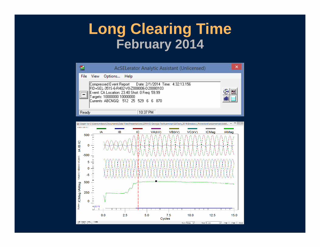
Long Clearing TimeFebruary 2014
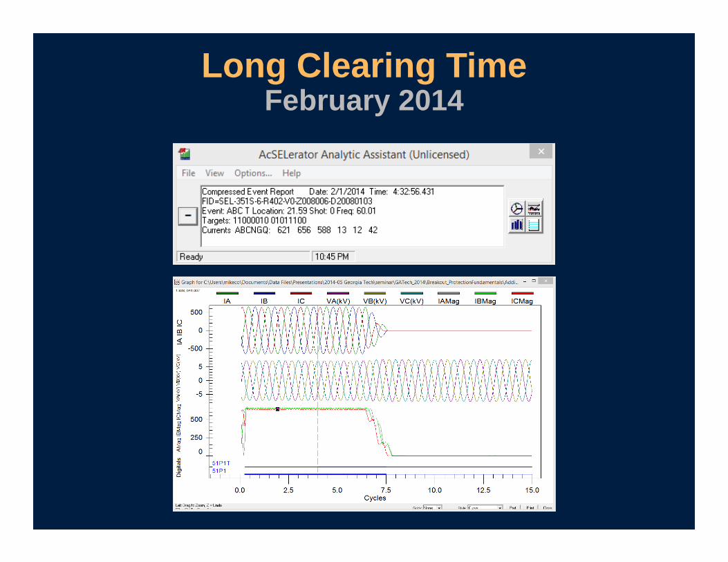
Long Clearing TimeFebruary 2014
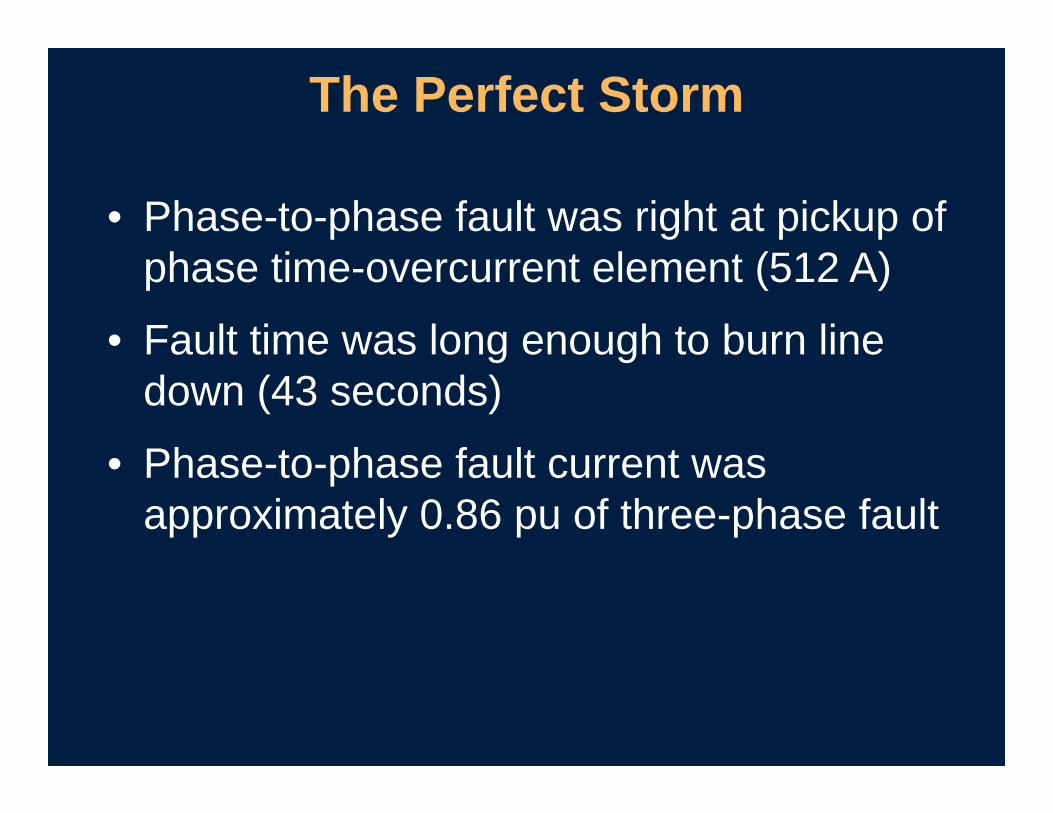
• Phase-to-phase fault was right at pickup of phase time-overcurrent element (512 A)
• Fault time was long enough to burn line down (43 seconds)
• Phase-to-phase fault current was approximately 0.86 pu of three-phase fault
The Perfect Storm
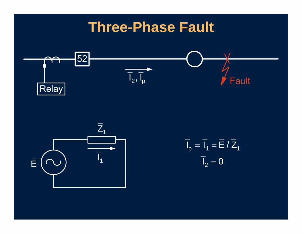
Three-Phase Fault
2 pI , I
1I
1Z
E
p 1 1
2
I I E / Z
I 0
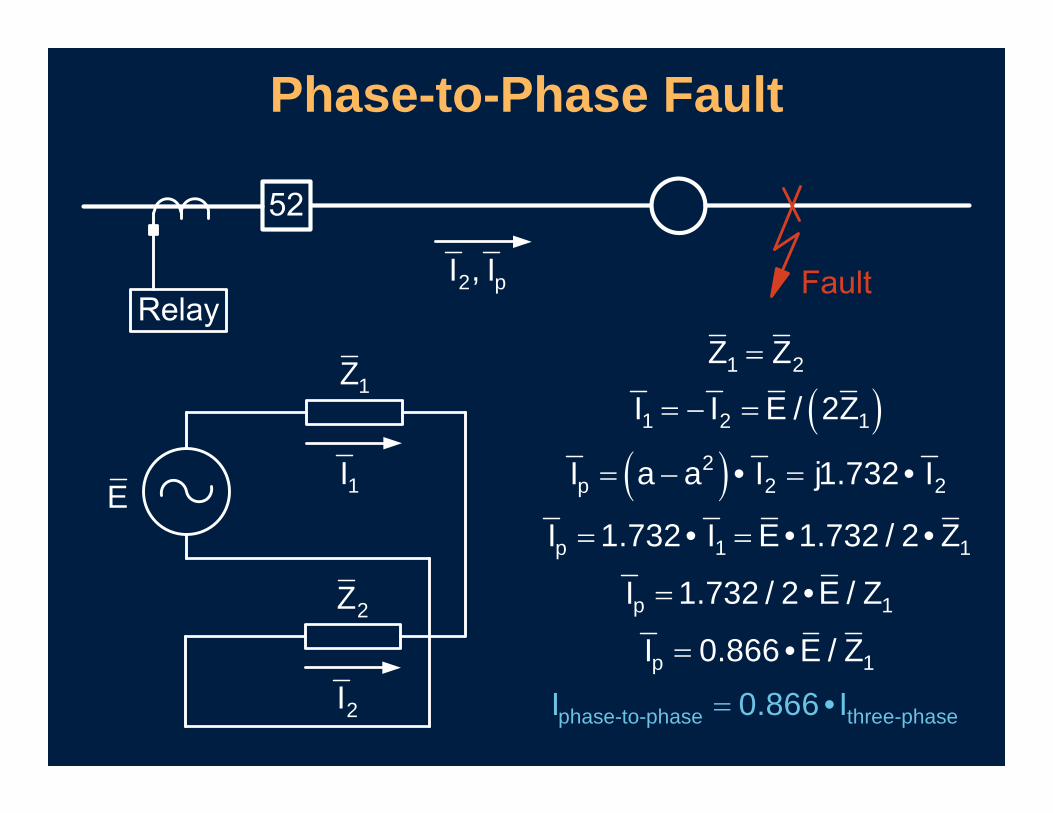
Phase-to-Phase Fault
2 pI , I
1I
1Z
E
2I
2Z
1 2
1 2 1
2p 2 2
p
phase-to-
1 1
phase three-pha
1
1
se
p
p
Z Z
I I E / 2Z
I a a • I j1.732• I
I 1.732• I E •1.732 / 2 • Z
I 0.866 • I
I 1.732 / 2 •E / Z
I 0.866 •E / Z
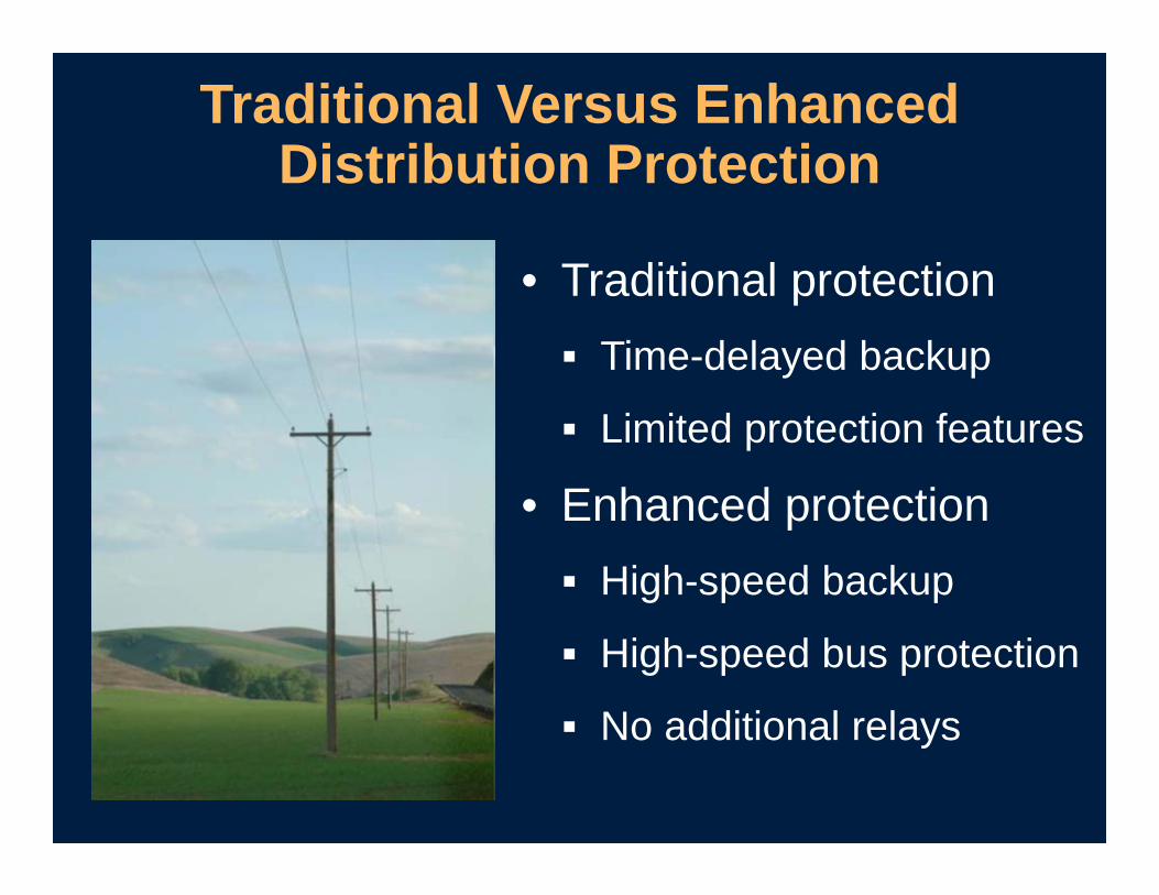
• Traditional protection Time-delayed backup
Limited protection features
• Enhanced protection High-speed backup
High-speed bus protection
No additional relays
Traditional Versus Enhanced Distribution Protection
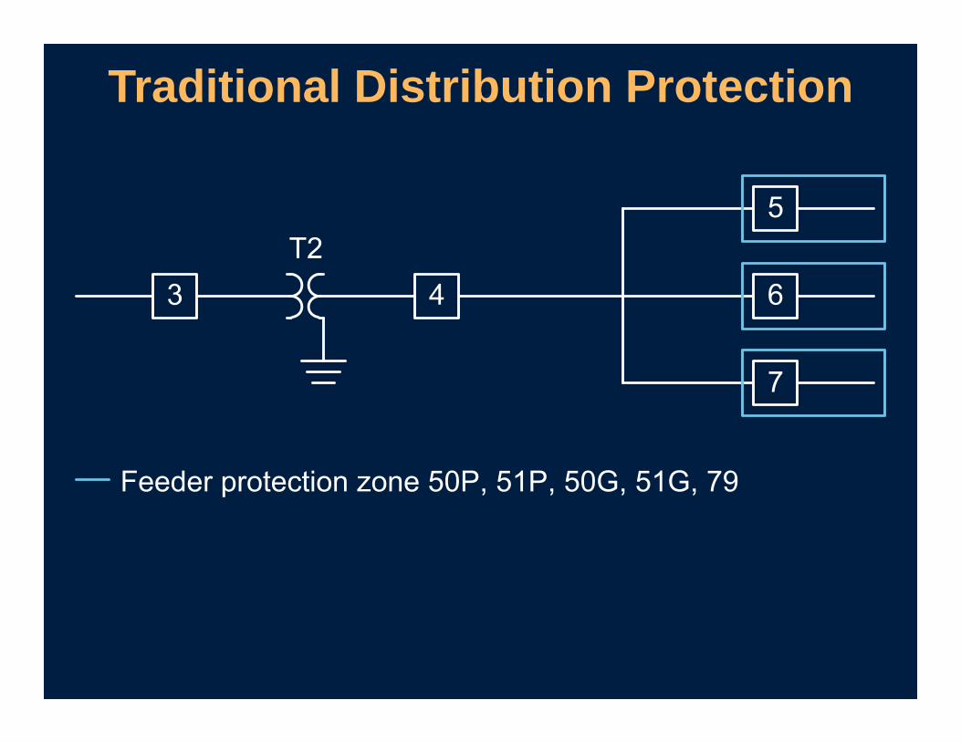
Traditional Distribution Protection

Enhanced Feeder Protection

Traditional Overcurrent Protection

Traditional Overcurrent Protection
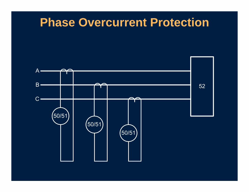
Phase Overcurrent Protection
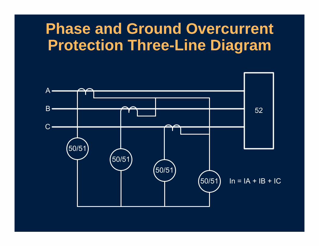
Phase and Ground Overcurrent Protection Three-Line Diagram
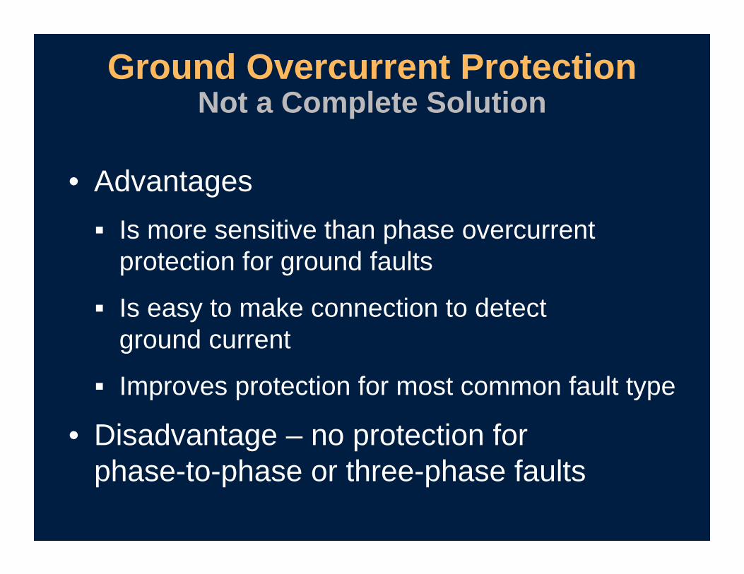
• Advantages Is more sensitive than phase overcurrent
protection for ground faults
Is easy to make connection to detect ground current
Improves protection for most common fault type
• Disadvantage – no protection for phase-to-phase or three-phase faults
Ground Overcurrent Protection Not a Complete Solution

Introduction to Negative-Sequence Overcurrent Elements
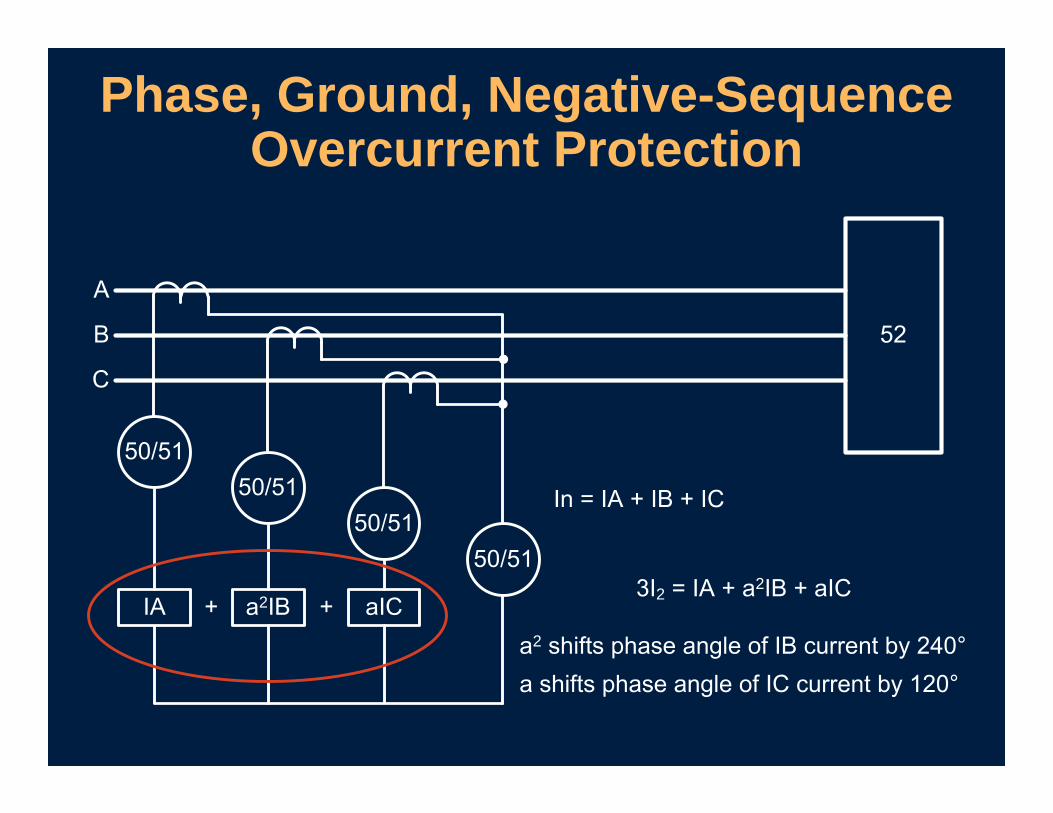
Phase, Ground, Negative-Sequence Overcurrent Protection
2 2 2
2

• Advantages Is more sensitive than phase overcurrent
protection for phase-to-phase faults
Is easy to calculate negative sequence in relay
Improves protection for second most common fault type
• Disadvantage – not sensitive tothree-phase faults
Phase-to-Phase Fault DetectorNegative-Sequence Overcurrent Element
Setting Negative-Sequence Overcurrent Elements
• Usually next downstream overcurrent device
• Typically no downstream negative-sequence overcurrent device
Step 1: Find Downstream Phase Overcurrent Device of
Greatest Coordination Concern

• As equivalent phase time-overcurrent element backup
• As being located at downstream device
Step 2: Think of Negative-Sequence Element
• Same curve shape
• Coordination margin of 12 to 30 cycles
• Same pickup plus 10%
Step 3: Perform Typical Phase Coordination With Downstream
Phase Overcurrent Device
3
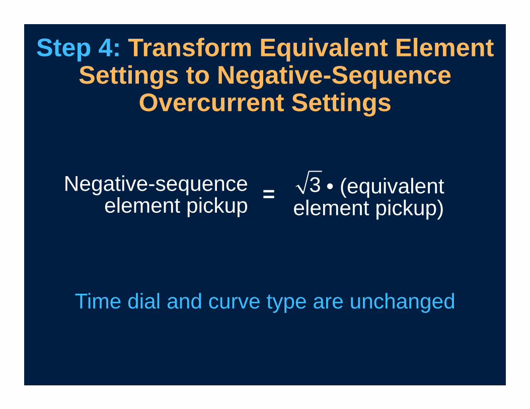
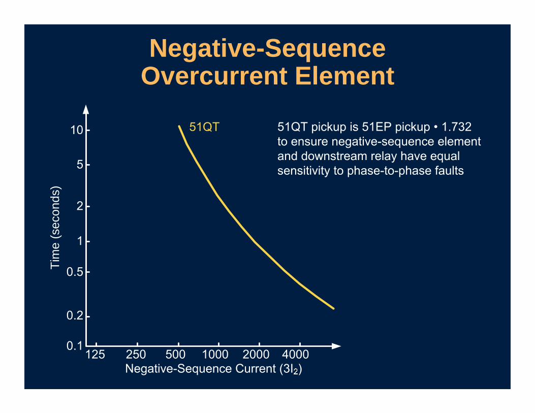
Step 4: Transform Equivalent Element Settings to Negative-Sequence
Overcurrent Settings
• (equivalent element pickup)
Negative-sequence element pickup =
Time dial and curve type are unchanged
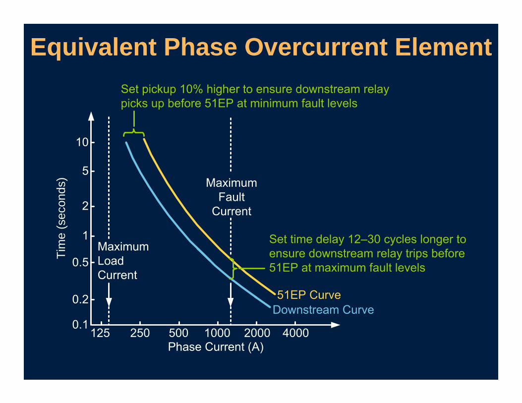
Equivalent Phase Overcurrent ElementTi
me
(sec
onds
)
Tim
e (s
econ
ds)
Negative-Sequence Overcurrent Element
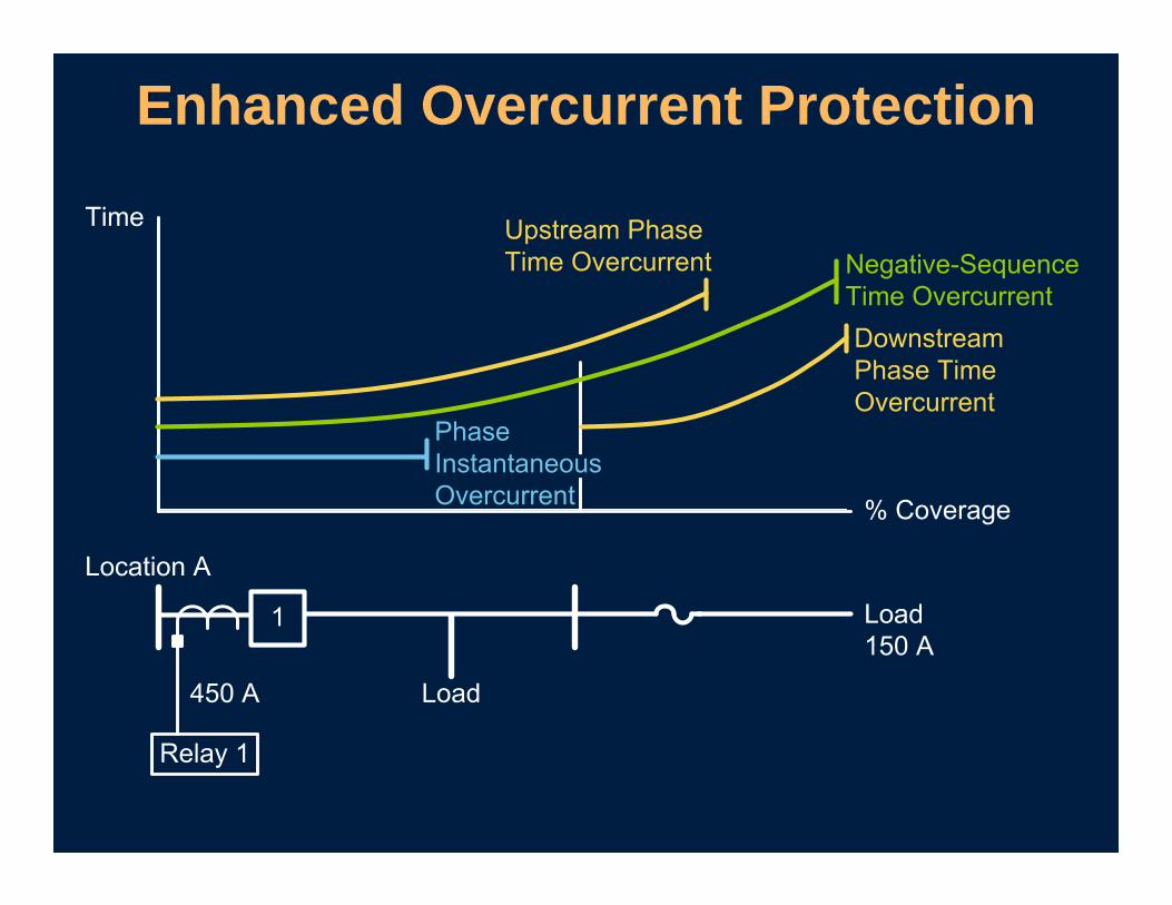
Enhanced Overcurrent Protection
• Are immune to balanced load conditions
• Improve sensitivity to phase-to-phase faults
• Can be easily implemented in microprocessor-based relays
• Are easy to set
Negative-Sequence Elements
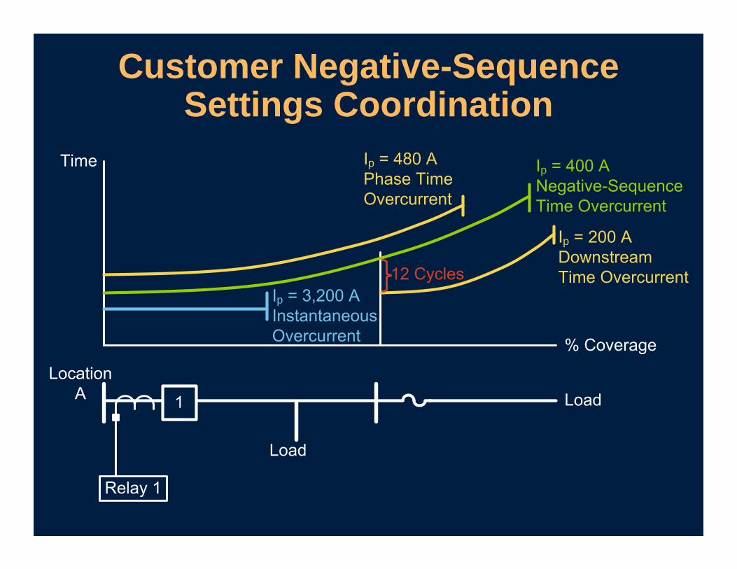
Customer Negative-Sequence Settings Coordination
p
p
p
p
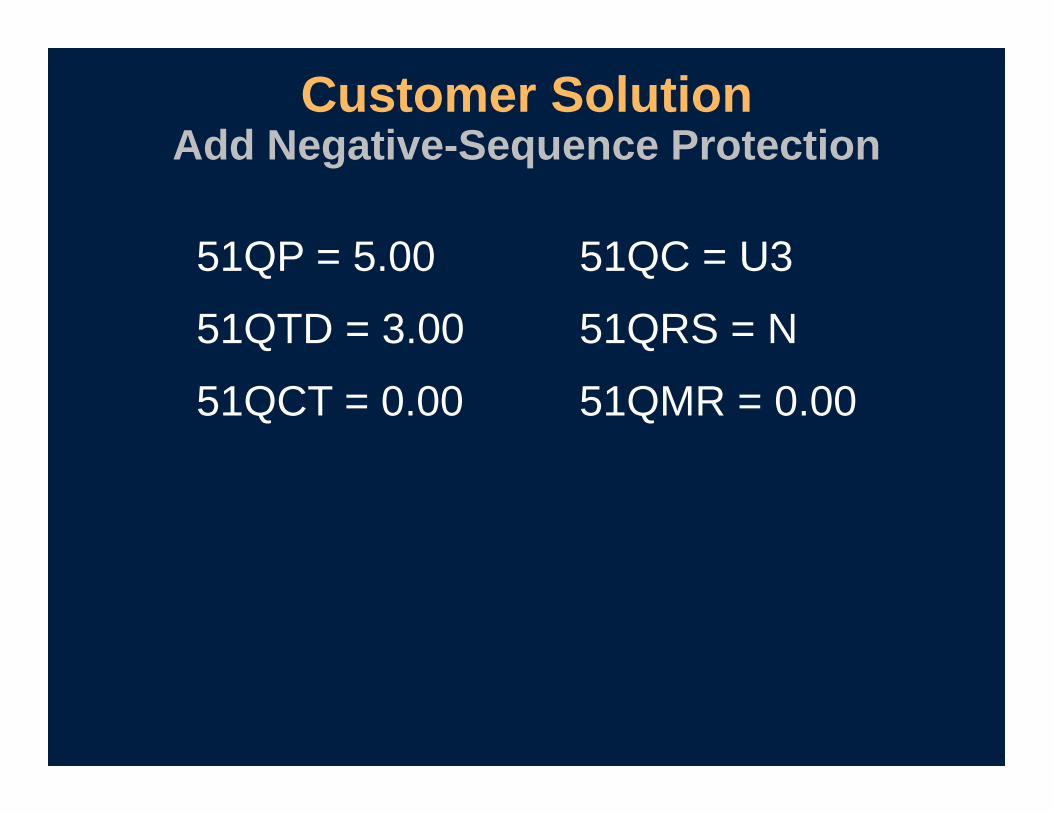
51QP = 5.00 51QC = U3
51QTD = 3.00 51QRS = N
51QCT = 0.00 51QMR = 0.00
Customer SolutionAdd Negative-Sequence Protection

• Old TR = 50P1 + 51P1T + (51G1T + 50G1) * LT1 + OC + 81D2T + (51P1 + 51G1) * !LT5 + (PB8 * SV2T)
• New TR = 50P1 + 51P1T + (51G1T + 50G1 + 51QT) * LT1 + OC * LT3 + (51P1+ 51G1) * !LT5 + (PB8 * SV2T)
Customer SolutionAdd Negative-Sequence Protection
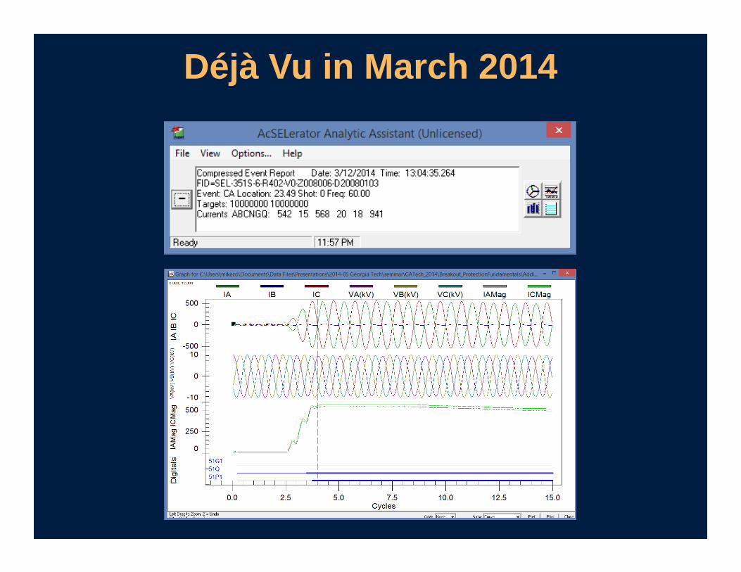
Déjà Vu in March 2014
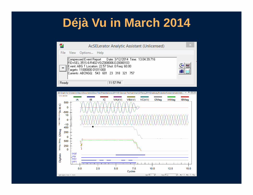
Déjà Vu in March 2014

• 51QT clearing time of 4 seconds
Line was not damaged
• Phase fault current
540 A (1.125 multiples of pickup)
• Negative-sequence fault current
3I2 = 981 A (2.45 multiples of pickup)
Noticeable Improvement

Negative-Sequence Differential Element
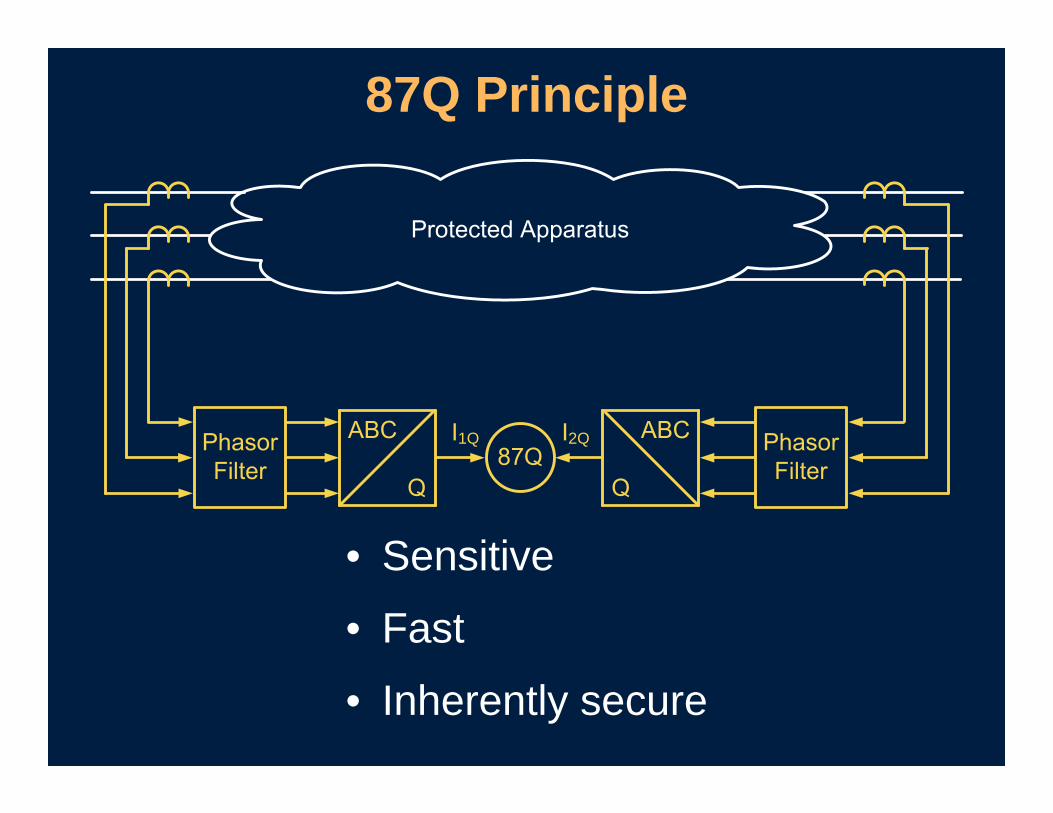
87Q Principle
• Sensitive
• Fast
• Inherently secure
1Q 2Q
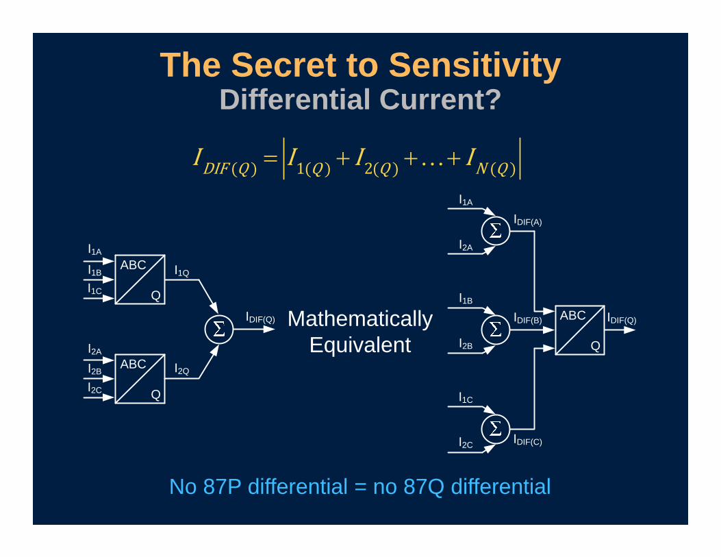
The Secret to SensitivityDifferential Current?
ABC
Q
ABC
Q
I1A
I1B
I1C
I2A
I2B
I2C
I1Q
I2Q
IDIF(Q) ABC
Q
I1A
I2A
I1B
I2B
I1C
I2C
IDIF(A)
IDIF(B)
IDIF(C)
IDIF(Q)MathematicallyEquivalent
No 87P differential = no 87Q differential
1 2DIF Q Q Q N Q
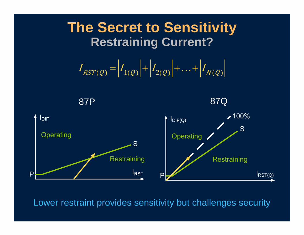
The Secret to SensitivityRestraining Current?
87P 87Q
Lower restraint provides sensitivity but challenges security
RST(Q)
DIF(Q)
1 2RST Q Q Q N Q
Restraining Current Purpose
Reflect the stress on protection system components, CTs in particular, that can cause
spurious differential current
Negative-sequence restraining current does not meet this requirement for
balanced faults / events
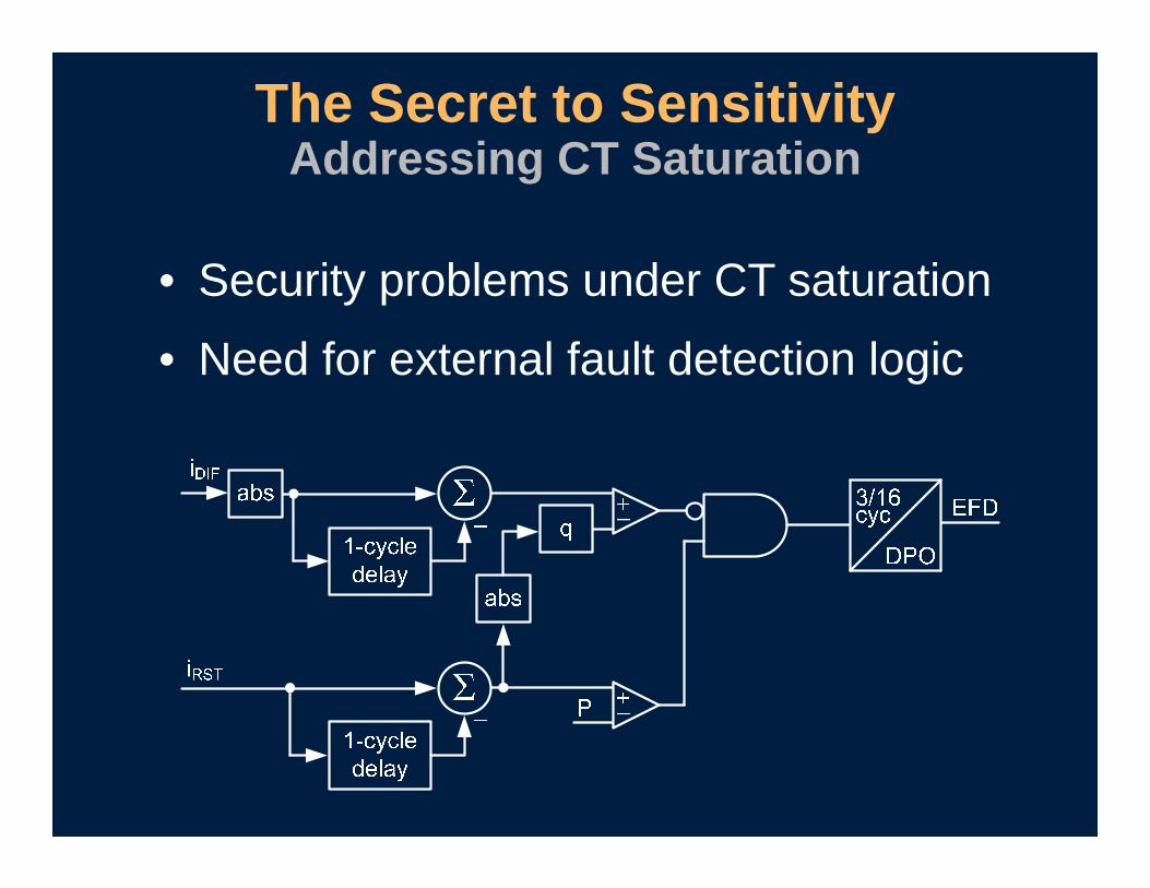
• Security problems under CT saturation
• Need for external fault detection logic
The Secret to SensitivityAddressing CT Saturation
• Is excellent for protecting lines and transformers
• Needs security for CT saturation
Negative-Sequence Differential
Negative-Sequence Directional Element

Negative-Sequence EquationsVoltage and Current
22
22
2
3
3where 1 120
and 1 240
A B C
A B C
V V a V aV
I I a I aIa
a

• Positive torque indicates forward direction
• Negative torque indicates reverse direction
Traditional Negative-Sequence Directional Element
2 2 2 2
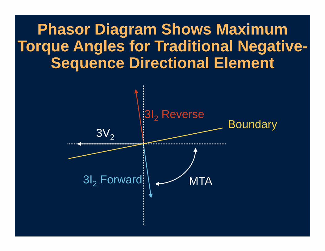
Phasor Diagram Shows Maximum Torque Angles for Traditional Negative-
Sequence Directional Element
3V2
3I2 Forward
3I2 Reverse
MTA
Boundary
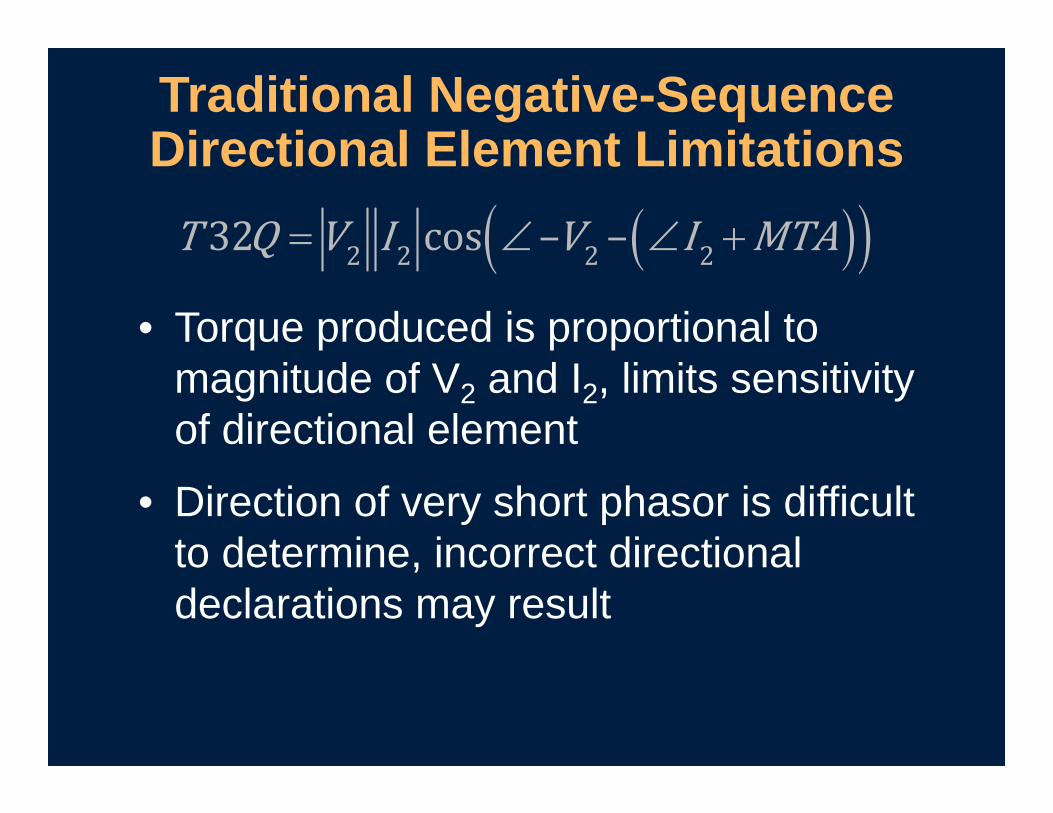
• Torque produced is proportional to magnitude of V2 and I2, limits sensitivity of directional element
• Direction of very short phasor is difficult to determine, incorrect directional declarations may result
Traditional Negative-Sequence Directional Element Limitations
2 2 2 2
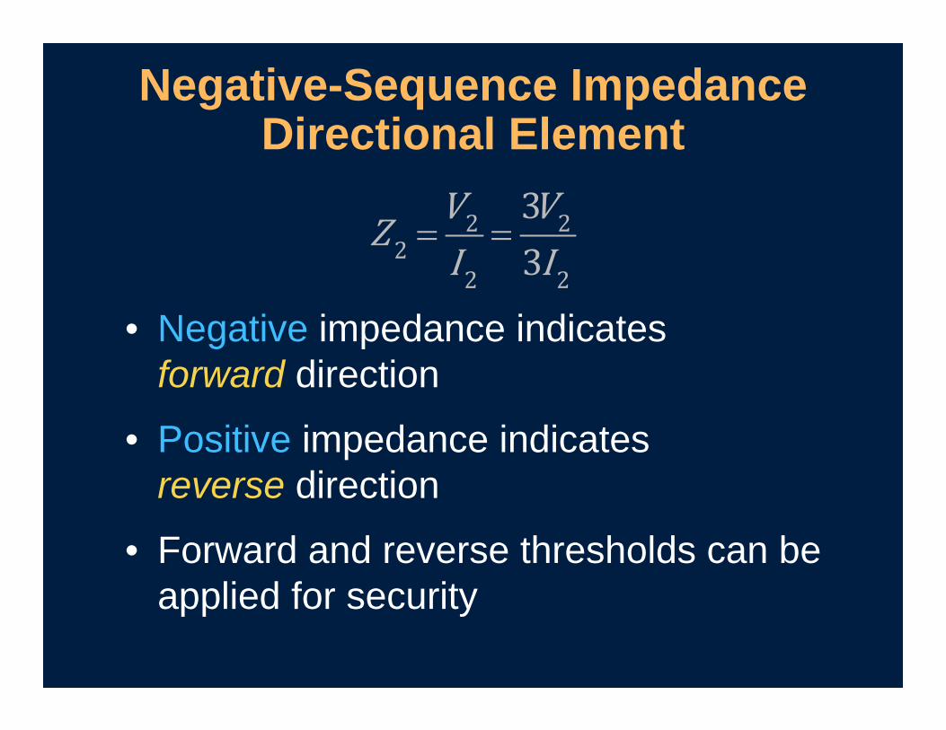
• Negative impedance indicates forward direction
• Positive impedance indicates reverse direction
• Forward and reverse thresholds can be applied for security
Negative-Sequence Impedance Directional Element
2 22
2 2

Negative-Sequence Impedance Directional Element
22
2
3VZ3I
2
2
2

• Direction can be determined for faults with essentially zero negative-sequence voltage
• Directional element has greater sensitivity
Negative-Sequence Impedance Directional Element
2 22
2 2
Negative Sequence for Fault Location
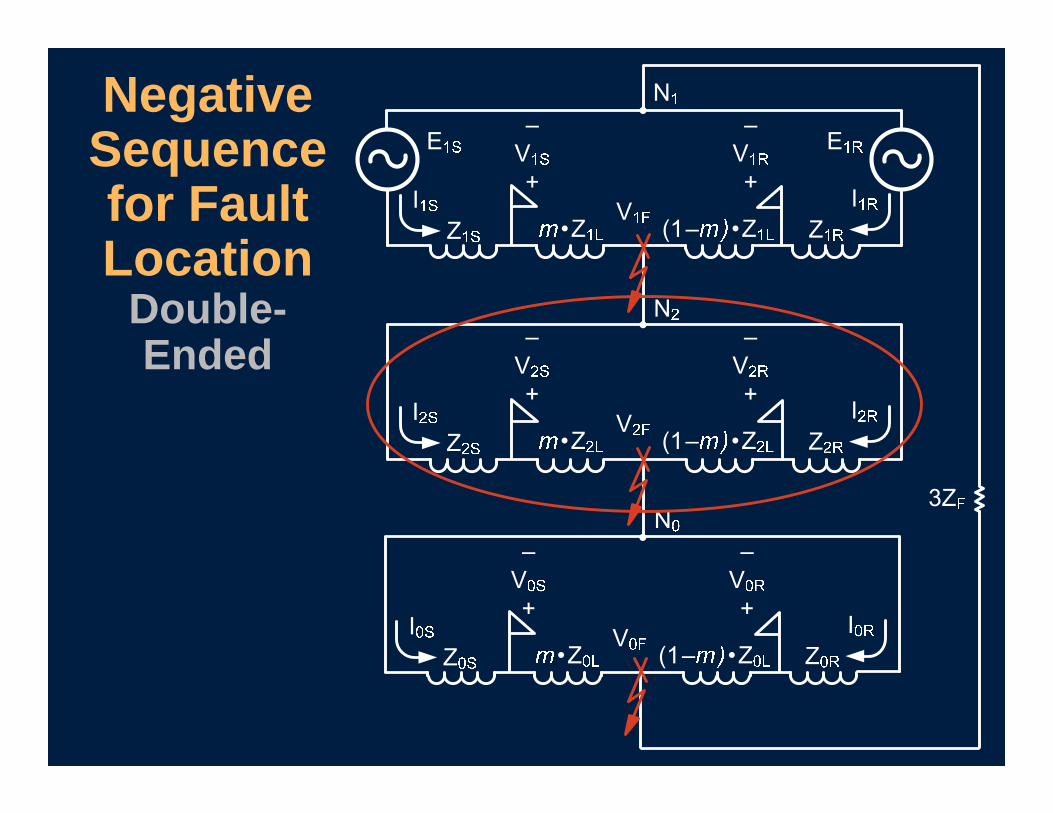
Negative Sequence for Fault Location
Double-Ended
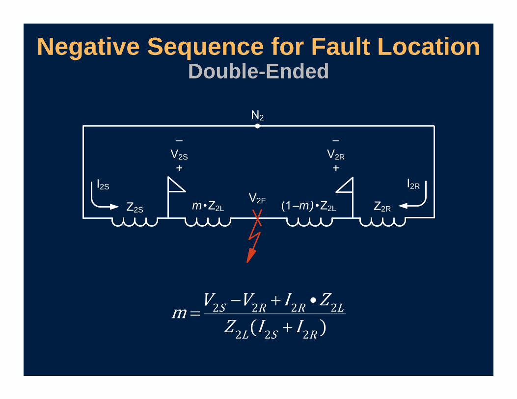
Negative Sequence for Fault LocationDouble-Ended
2
2S
2S
2S 2R
2R
2Rm 2L m) 2L2F
2 2 2 2
2 2 2
S R R L
L S R

• Include voltage, current, and impedance
• Can be used for overcurrent, differential, directional, and fault location elements
• Are already built in to many digital relays; just need to be enabled
Negative-Sequence Quantities
Understand elements and associated settings before applying

Questions?