nd9000 intelligent valve controller - · pdf filend9000® intelligent valve controller ......
TRANSCRIPT

7 ND
90 21 EN • 1/2011
ND9000® INTELLIGENT VALVE CONTROLLER
Neles ND9000 is a top class intelligent valve controller designed to operate on every control valve actuator and in all industry areas. It guarantees the end product quality in all operating conditions with unique diagnostics and incomparable performance features. ND9000 is a reliable and future-proof investment with Metso FieldCare™ life-time support
KEY FEATURES□ Benchmark control performance on rotary and
linear valves□ Reliable and robust design□ Easy commissioning and operation□ Language selection: English, German and French□ Local / remote operation□ Expandable architecture□ Advanced device diagnostics including
□ Self-diagnostics□ Online diagnostics□ Performance diagnostics□ Communication diagnostics□ Extended off-line tests□ Intelligent Valve Diamond
Options□ Interchangeable communication options:
□ HART□ FOUNDATION fieldbus□ Profibus PA
□ Limit switches□ Position transmitter (in HART only)□ Full stainless steel enclosure□ Exhaust adapter
Total cost of ownership□ Low energy and air consumption□ Future proof design allows further options at a
reduced cost□ Optimized spares program minimizes spare part
inventory□ Retro-fit to existing installations (Neles or 3rd party
valves)
Minimised process variability□ Linearisation of the valve flow characteristics□ Excellent dynamic and static control performance□ Fast response to control signal change□ Accurate internal measurements
Easy installation and configuration□ Same device can be used for linear and rotary
valves, double and single-acting actuators□ Simple fast calibration and configuration
□ using Local User Interface (LUI)□ using FieldCare software in a remote location□ using Distributed Control System (DCS) asset
management tools
□ Flush mounting capability to avoid tubing andmounting parts
□ Low power comsumption enables installation to allcommon control systems
Open solution□ Metso is committed to delivering products that
freely interface with software and hardware from avariety of manufacturers; ND9000 is no exception.This open architecture allows the ND9000 to beintegrated with other field devices to give anunprecedented level of controllability.
□ FDT and EDD based multi-vendor support configu-ration
□ Support files for ND9000 are available from ourinternet page, at www.metso.com/valves - chooselink download center

M E T S O
2
7 N D 9 0 2 1 E N
Neles ND9000 in fieldbus networks□ Approved interoperability
□ Host interoperability ensured□ FOUNDATION fieldbus ITK version 5.01 certified□ Profibus PA profile version 3.0 PNO certified
□ Easy to upgrade; can be done by replacing the HARTcommunication board to fieldbus communication board
□ Excellent maintainability with firmware download feature□ Advanced communication diagnostics□ Digital communication via the fieldbus includes not only
the set point, but also the position feedback signal fromthe position sensor. No special supplementary modulesfor analog or digital position feedback are needed whenusing the fieldbus valve controller.
□ Back up LAS functionality available in FOUNDATION field-bus enviroment
□ Input selector and output splitter blocks available in FOUN-DATION fieldbus devices allowing advanced distributedcontrol
□ Standard function blocks enables the freedom to useND9000 intelligent valve controller either in continuous oron-off control applications
□ Open and close information is directly available via thefieldbus
□ Open and close detection is based on either positionmeasurement (soft limit switch) or mechanical limit switch information
ND9000 mounting on actuators and valves□ Mounted on single and double acting actuators□ Both rotary and linear valves□ Ability to attach options to electronics and mechanics later□ 1-point calibration feature enables mounting without dis-
turbing the process
Product reliability□ Designed to operate in harsh environmental conditions□ Rugged modular design□ Excellent temperature characteristics□ Vibration and impact tolerant□ IP66 enclosure□ Stainless steel enclosure (ND9300)□ Protected against humidity□ Maintenance free operation□ Resistant to dirty air□ Wear resistant and sealed components□ Contactless position measurement
Predictive maintenance□ Easy access to collected data with Metso FieldCare soft-
ware□ Intelligent Valve Diamond to visualise control valve per-
formance & diagnostics□ Logical trend and histogram collection□ Information collected during process uptime□ Extensive set of off-line tests with accurate key figure cal-
culations□ Fast notifications with on-line alarms□ Condition monitoring tool available
TECHNICAL DESCRIPTIONThe ND9000 is a 4–20 mA or fieldbus powered microcontrol-ler-based intelligent valve controller. The device contains aLocal User Interface (LUI) enabling local configuration. A PCwith FieldCare software can be connected to the ND9000itself or to the control loop.
The powerful 32-bit microcontroller controls the valve posi-tion. The measurements include:□ Input signal□ Valve position with contactless sensor□ Actuator pressures, 2 independent measurements□ Supply pressure□ Spool valve position□ Device temperature
Advanced self-diagnostics guarantees that all measure-ments operate correctly. After connections of electric signaland pneumatic supply the micro controller (μC) reads theinput signal, position sensor (α), pressure sensors (Ps, P1,P2) and spool position sensor (SPS). A difference betweeninput signal and position sensor (α) measurement isdetected by control algorithm inside the μC. The μC calcu-lates a new value for prestage (PR) coil current based on theinformation from the input signal and from the sensors.Changed current to the PR changes the pilot pressure to thespool valve. Reduced pilot pressure moves the spool and theactuator pressures change accordingly. The spool opens theflow to the driving side of the double diaphragm actuator andopens the flow out from the other side of the actuator. Theincreasing pressure will move the diaphragm piston. Theactuator and feedback shaft rotate. The position sensor (α)measures the rotation for the μC. The μC using control algo-rithm modulates the PR-current from the steady state valueuntil a new position of the actuator according to the input sig-nal is reached.
TECHNICAL BULLETIN 1/11

N D 9 0 0 0 F ® I N T E L L I G E N T V A L V E C O N T R O L L E R7 N D 9 0 2 1 E N
TECHNICAL SPECIFICATIONSND9000 INTELLIGENT VALVE CONTROLLER
GeneralLoop powered, no external power supply required.Suitable for rotary and linear valves.Actuator connections in accordance with VDI/VDE 3845 andIEC 60534-6 standards.Flush mounting on selected actuatorsAction: Double or single actingTravel range: Linear; 10–120 mm / 0.4-4.7 in
rotary; 45–95 degrees. Measurement range 110° with freely rotating feedback shaft.
Environmental influenceStandard temperature range:
-40° – +85 °C / -40° – +185 °FInfluence of temperature on valve position:
0.5 % /10 °KInfluence of vibration on valve position:
< 1 % under 2g 5–150 Hz,1g 150–300 Hz, 0.5g 300–2000 Hz
EnclosureMaterial: ND9100: Anodized aluminium alloy
and polymer compositeND9200: Anodised aluminium alloy and tempered glass ND9300: Full 316 stainless steel
Protection class: IP66, Nema 4xPneumatic ports: G 1/4 (ND9100)
1/4 NPT (ND9200 and ND9300)Cable gland thread: M20x1.5 (ND9000 )
1/2 NPT ((ND9000E2, ND9000U1 and ND9000U2)
Weight: 1.8 kg / 4.0 lbs (ND9100)3.4 kg / 7.5 lbs (ND9200)8.6 kg / 19.0 lbs (ND9300)
Mechanical and digital position indicator visible throughmain cover, not applicable ND9200E2 and ND9300.Special corrosion resistance design or stainless steel hous-ing available as an option for demanding environment.
PneumaticsSupply pressure: 1.4–8 bar / 20–115 psiEffect of supply pressure on valve position:
< 0.1 % at 10 % difference in inlet pressure
Air quality: Acc. to ISO 8573-1Solid particles: Class 5 (3 – 5 μm filtration is recommended) Humidity: Class 1 (dew point 10 °C/ 18 °F below minimum temperature is recommended)Oil class: 3 ( or < 1 ppm)
Capacity with 4 bar / 60 psi supply:5.5 Nm3/h / 3.3 scfm (spool valve 2)12 Nm3/h / 7.1 scfm (spool valve 3)38 Nm3 /h /22,4 scfm (spool valve 6)
Consumtion with 4 bar / 60 psi supply in steady state position:< 0.6 Nm3/h /0.35 scfm (spool valve 2 & 3)< 1.0 Nm3/h / 0.6 scfm (spool valve 6)
ElectronicsHARTSupply power: Loop powered, 4–20 mAMinimum signal: 3.6 mACurrent max : 120 mALoad voltage: up to 9.5 VDC/20 mA
(corresponding 475 Ω)Voltage: max. 30 VDCPolarity protection: -30 VDCOver current protection: active over 35 mA
Profibus PA and FOUNDATION fieldbusSupply power: voltage 9–32 VDC, reverse polarity
protectionMax basic current 17.2 mAFault current (FDE) 3.9 mA
FOUNDATION fieldbus function block execution times
AO 20 msPID 25 msDO 15 msDI 15 msIS 15 msOS 20 ms
Performance with moderate constant-load actuators EC05-EC10 in ambient temperature
Dead band acc. to IEC 61514: ≤ 0.1 %Hysteresis acc. to IEC 61514: < 0.5 %
Local User Interface (LUI) functions□ Local control of the valve□ Monitoring of valve position, target position, input signal,
temperature, supply and actuator pressure difference□ Guided-startup function□ LUI may be locked remotely to prevent unauthorised
access□ Calibration: Automatic / Manual linearization□ 1-point calibration□ Control configuration: aggressive, fast, optimum, stable,
maximum stability□ Configuration of the control valve
□ Rotation: valve rotation clockwise or counter-clockwiseto close
□ Dead Angle□ Low cut-off, cut-off safety range (default 2 %)□ Positioner fail action, open/close□ Signal direction: Direct/reverse acting□ Actuator type, double/single acting□ Valve type, rotary/linear□ Language selection: English, German and French
Position transmitter (optional)Output signal: 4–20 mA (galvanic isolation;
600 VDC)Supply voltage: 12–30 VDCResolution: 16 bit / 0.244 μALinearity: < 0.05 % FSTemperature effect: < 0.35 % FSExternal load: max 0–780 Ω
max 0–690 Ω for intrinsically safeEx ia IIC T6 Ui ≤ 28 VEx d IIC T4/T5/T6 Ui ≤ 30 V
TECHNICAL BULLETIN 1/11 3

M E T S O
4
7 N D 9 0 2 1 E N
TECHNICAL BULLETIN 1/11
APPROVALS ND9100 and ND9300Intrinsically safe and non incendiveATEXEC-Directive 94/9/EC;II 1 G, Ex ia IIC T4/T5/T6 GaII 1 D, Ex tD A20 T 90 °CII 2 G, Ex ia IIC T4/T5/T6 GbII 2 D, Ex tD A21 T 90 °CII 3 G, Ex nA IIC T4/T5/T6 GcII 3 D, Ex tD A22 T90 °CII 3 G, Ex nL IIC T4/T5/T6 GcII 3 D, Ex tD A22 T90 °C
IECEx Ex ia IIC T4/T5/T6 GaEx tD A20 T90 °CEx ia IIC T4/T5/T6 GbEx tD A21 T90 °CEx nA IIC T4/T5/T6 GcEx nL IIC T4/T5/T6 GcEx tD A22 T90 °C
CSAIS Class I, Div. 1, Groups A, B, C, D T4...T6IS Class I, Zone 0, Ex ia IIC T4...T6NI Class I, Div. 2, Groups A, B, C, D T4...T6
FMIS Class I, Div. 1, Groups A, B, C, D T4...T6IS Class I, Zone 0, AEx ia IIC T4...T6NI Class I, Div. 2, Groups A, B, C, D T4...T6NI Class I, Zone 2, Ex nA IIC T4...T6
INMETRO BR-Ex ia IIC T4/T5/T6 IP66BR-Ex nA II / nL IIC T4/T5/T6 IP66
APPROVALS ND9200 and ND9300Flameproof and explosion proofATEXEC-Directive 94/9/EC;II 2 G Ex d IIC T4...T6 II 2 D Ex tD A21 IP66 T 100 °C
IECEx Ex d IIC T4...T6Ex tD A21 IP66 T100 °C
INMETRO BR-Ex d IIC, T4/T5/T6, IP66
APPROVALS ND9200Flameproof and explosion proofFMExplosion proof Class I, II and III,Division 1 and 2, Groups A, B, C, D, E, F
CSAClass 1, Div 1 Groups B, C, DClass 2, Div.1 Groups E, F, G, Class III T4 ...T6, Ex d IIC T4 ... T6 DIP A21 Ta 100 °C IP 66
TIIS (JIS) Ex d II C T6
Electromagnetic ProtectionElectromagnetic compatibilityEmission acc. to EN 61000-6-4 (2001)and FCC 47 CFR PART 15,SUBPART B, CLASS B (1994)Immunity acc. to EN 61000-6-2 (2001)
PROXIMITY SENSORS AND LIMIT SWITCHES(OPTIONAL WITH EXTENSION MODULE FOR
ND9100 & ND9200)Code I02 P+F NJ2-12GK-SN, 2 sensorsCode I09 P+F; NCB2-12GM35-N0Code I56 IFC 2002-ARKG/UP, 2 sensorsCode K05 Omron D2VW-5, micro switch, 2 sensorsCode K06 Omron D2VW-01 gold plated, micro switchCode B06 Omron D2VW-01 gold plated, micro switch, 2 sen-sors. (Bus powered, no external power and cabling needed).
Fig. 1. Local User Interface (LUI) enables real time aware-ness of control parameters in the device at a glance.
Fig. 2. Trend collection enables fast and easy predictivemaintenance. The need for maintenance is reduced andincreased plant and process availability are realised.
N D 9 0 0 0 F ® I N T E L L I G E N T V A L V E C O N T R O L L E R7 N D 9 0 2 1 E N
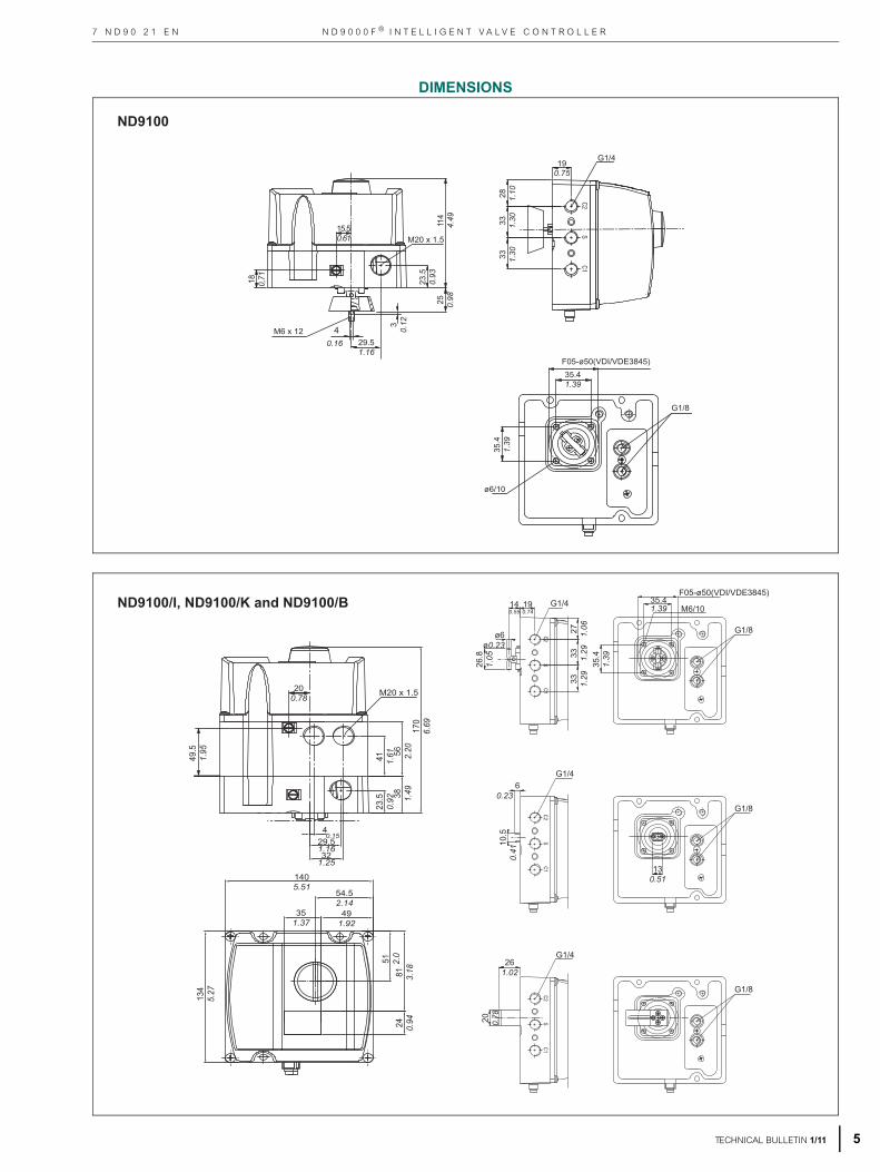
DIMENSIONS
M6 x 12 40.16 29.5
1.16
114
4.49
25 0.98
23.5
0.93
30.
12
M20 x 1.5
33 1.30
33 1.30
28 1.10
190.75
G1/4
35.41.39
35.4
1.39
F05-ø50(VDI/VDE3845)
ø6/10
G1/8
15.50.61
18 0,71
ND9100
190.74
140.55
26.8
1.05
ø6ø0.23
33 1.29
27 1.06
35.41.39
35.4
1.39
F05-ø50(VDI/VDE3845)
60.23
10.5
0.41
130.51
20 0.78
261.02
M6/10G1/4
G1/4
G1/4
G1/8
G1/8
G1/8
33 1.29
170
6.69
56 2.20
38 1.49
4
41 1.61
23.5
0.92
29.51.1632
1.25
1405.51
54.52.14
51 2.0
134
5.27
81 3.18
24 0.94
491.92
351.37
M20 x 1.5
0.15
49.5
1.95
200.78
ND9100/I, ND9100/K and ND9100/B
TECHNICAL BULLETIN 1/11 5

M E T S O
6
7 N D 9 0 2 1 E N
TECHNICAL BULLETIN 1/11
1/4 NPT
39 1.54
522.05
33 1.30
33 1.30
140.55
26.8
1.05
ø6ø0.23
35.41.39
35.4
1.39
F05-
ø50
(VD
I/VD
E 3
845)
M6
10.5
0.41
60.23
130.51
101.23.98
1626.37
63 2.48
161
6.33
ND9200
133
5.23
M20x1.5(1/2 NPT)
47 1.85
331.30
331.30
391.54
52 2.05
1/4 NPT
35.41.39
M6
35.4
1.39
M6 x 12 40.16 25
0.98
25 0.98
30.
12
140.55
15 0.59
ND9200

N D 9 0 0 0 F ® I N T E L L I G E N T V A L V E C O N T R O L L E R
7
7 N D 9 0 2 1 E N
TECHNICAL BULLETIN 1/11
95 3.74
190
7.48
M20x1.5(1/2 NPT)
1034.05
1746.85
63 2.48
161
6.33
min
. 60
2.4
47 1.85
M6 x 12 40.16 25
0.98
25 0.98
30.
12
140.55
15 0.59
1/4 NPT
39 1.54
522.05
33 1.30
33 1.30
140.55
26.8
1.05
ø6ø0.23
35.41.39
35.4
1.39
F05-
ø50
(VD
I/VD
E 38
45)
M6
101.23.98
1626.37
63 2.48
161
6.33
ND9200/I, ND9200/K, ND9200/B
133
5.23
M20x1.5(1/2 NPT)
47 1.85
331.30
331.30
391.54
52 2.05
1/4 NPT
35.41.39
M6
35.4
1.39
M6 x 12 40.16 25
0.98
25 0.98
30.
128 0.31
793.11
M8
562.20
ND9300

M E T S O
8
7 N D 9 0 2 1 E N
1/4 NPT
39 1.54
522.05
33 1.30
33 1.30
140.55
26.8
1.05
ø6ø0.23
35.41.39
35.4
1.39
F05-
ø50
(VD
I/VD
E 3
845)
M6
1034.05
1636.42
63 2.48
161
6.33
ø562.20
M8
ND9300
TECHNICAL BULLETIN 1/11
N D 9 0 0 0 F ® I N T E L L I G E N T V A L V E C O N T R O L L E R
9
7 N D 9 0 2 1 E N
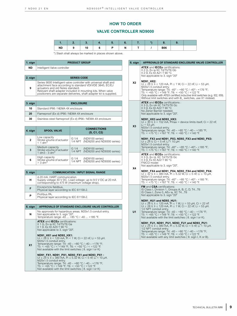
HOW TO ORDER
VALVE CONTROLLER ND9000
1. 2. 3. 4. 5. 6. 7. *) 8. 9.
ND 9 10 6 P N T / B06
TECHNICAL BULLETIN 1/11
*) Slash shall always be marked in places shown above.
1. sign PRODUCT GROUP
ND Intelligent Valve controller
2. sign SERIES CODE
9
Series 9000 Intelligent valve controller with universal shaft and attachment face according to standard VDI/VDE 3845, EC/EJ actuators and old Neles standard.Relevant shaft adapter included in mounting kits. When valve positioners are separate deliveries, shaft adapter kit is supplied.
3. sign ENCLOSURE
10 Standard IP66 / NEMA 4X enclosure
20 Flameproof (Ex d) IP66 / NEMA 4X enclosure
30 Stainless steel flameproof (Ex d) IP66 / NEMA 4X enclosure
4. sign SPOOL VALVE CONNECTIONS(S, C1, C2)
2Low capacityStroke volume of actuator < 1 dm3
G 1/4 (ND9100 series)1/4 NPT (ND9200 and ND9300 series)
3Medium capacityStroke volume of actuator 1 dm3 - 3 dm3
G 1/4 (ND9100 series)1/4 NPT (ND9200 and ND9300 series)
6High capacityStroke volume of actuator > 3 dm3
G 1/4 (ND9100 series)1/4 NPT (ND9200 and ND9300 series)
5. sign COMMUNICATION / INPUT SIGNAL RANGE
H4-20 mA, HART communication.Supply voltage 30 V DC. Load voltage: up to 9.5 V DC at 20 mA corresponding to 475 W (maximum voltage drop).
F FOUNDATION fieldbus, Physical layer according to IEC 61158-2.
P Profibus PA,Physical layer according to IEC 61158-2.
6. sign APPROVALS OF STANDARD ENCLOSURE VALVE CONTROLLER
NNo approvals for hazardous areas. M20x1.5 conduit entry.Not applicable to 3. sign "20".Temperature range -40 ... +85 °C / -40 ... +185 °F.
X1
ATEX and IECEx certifications:II 1 G, Ex ia IIC T4/T5/T6 Ga II 1 D, Ex tD A20 T 90 °CNot applicable to 3. sign "20".
ND91_HX1 and ND93_HX1: Ui < 28 V, Ii < 120 mA, Pi < 1 W, Ci = 22 nF, Li = 53 μH.M20x1.5 conduit entry.Temperature range: T4: -40 – +80 °C / -40 – +176 °F;T5: < +65 °C / < +149 °F; T6: < +50 °C / < +122 °F.Not available with the limit switches ( 8. sign I or K)
ND91_FX1, ND91_PX1, ND93_FX1 and ND93_PX1 : Ui ≤ 24 V, Ii ≤ 380 mA, Pi ≤ 5.32 W, Ci < 5 nF, Li < 10 μH.M20x1.5 conduit entry.Temperature range: T4: -40 – +80 °C / -40 – +176 °F;T5: < +65 °C / +149 °F; T6: < +50 °C / +122 °F.Not available with the limit switches ( 8. sign I or K)
6. sign APPROVALS OF STANDARD ENCLOSURE VALVE CONTROLLER
X2
ATEX and IECEx certifications:II 2 G, Ex ia IIC T4/T5/T6 GbII 2 D, Ex tD A21 T 90 °CNot applicable to 3. sign "20"
ND91_HX2: Ui ≤ 28 V, Ii ≤ 120 mA, Pi ≤ 1 W, Ci = 22 nF, Li = 53 μH.M20x1.5 conduit entry.Temperature range: T4: -40° – +80 °C / -40°– +176 °F;T5: < +65 °C / +149 °F; T6: < +50 °C / +122 °F.Only available with ATEX certified inductive limit switches (e.g. I02, I09).Without limit switches and with B_ switches, use X1 instead.
X3
ATEX and IECEx certifications :II 3 G, Ex nA IIC T4/T5/T6 GcII 3 D, Ex tD A22 T 90 °CNo Zener Barrier needed.Not applicable to 3. sign "20".
ND91_HX3 and ND93_HX3: Ui ≤ 30 V, Ii = 152 mA, Pmax = device limits itself, Ci = 22 nF, Li = 53 μH.M20x1.5 conduit entry.Temperature range: T4: -40 – +85 °C / -40 – +185 °F;T5: < +75 °C / +167 °F; T6: < +60 °C / +140 °F.
ND91_FX3 and ND91_PX3, ND93_FX3 and ND93_PX3:Ui ≤ 24 V, Ci < 5 nF, Li < 10 μHM20x1.5 conduit entry.Temperature range: T4: -40° – +85 °C / -40°– +185 °F;T5: < +75 °C / +167 °F; T6: < +60 °C / +140 °F.
X4
ATEX and IECEx certifications:II 3 G, Ex nL IIC T4/T5/T6 GcII 3 D, Ex tD A22 T 90 °CFNICO modelNot applicable to 3. sign "20".
ND91_FX4 and ND91_PX4, ND93_FX4 and ND93_PX4:Ui ≤ 32 V, Ii ≤ 380 mA, Pi ≤ 5.32 W, Ci ≤ 5 nF, Li ≤ 10 μH, M20x1.5 conduit entry.Temperature range: T4: -40° – +85 °C / -40°– +185 °F;T5: < +75 °C / +167 °F; T6: < +60 °C / +140 °F.
U1
FM and CSA certifications:IS Class I, Division 1, Groups A, B, C, D, T4...T6IS Class I, Zone 0, AEx ia, IIC T4...T6Not applicable to 3. sign "20"
ND91_HU1 and ND93_HU1: Ui ≤ 28 V, Ii ≤ 120 mA, Pi ≤ 1 W, Li = 53 μH, Ci = 22 nF.Ui ≤ 28 V, Ii ≤ 120 mA, Pi ≤ 1 W, Ci = 22 nF, Li = 53 μH.1/2 NPT conduit entry.Temperature range: T4: -40 – +80 °C / -40 – +176 °F;T5: < +65 °C / +149 °F; T6: < +50 °C / +122 °F.Not available with the limit switches ( 8. sign I or K).
ND91_FU1, ND91_PU1, ND93_FU1 and ND93_PU1: Ui ≤ 24 V, Ii ≤ 380 mA, Pi ≤ 5.32 W, Ci < 5 nF, Li < 10 μH.1/2 NPT conduit entry.Temperature range: T4: -40 – +80 °C / -40 – +176 °F;T5: < +65 °C / +149 °F; T6: < +50 °C / +122 °F.Not available with any limit switches ( 8. sign I, K or B).

M E T S O
1
7 N D 9 0 2 1 E N
6. sign APPROVALS OF STANDARD ENCLOSURE VALVE CONTROLLER
U2
FM and CSA certifications:NI Class I, Division 2, Groups A, B, C, D, T4...T6.NI Class I, Zone 2, Ex nA IIC T4...T6.No Zener Barrier needed. Not applicable to 3. sign "20"
ND91_HU2 and ND93_HU2:Ui ≤ 30 V, Pmax = device limits itself, Ci = 22 nF, Li = 53 μH, external load resistance 0–780 Ω1/2 NPT conduit entry.Temperature range: T4: -40 – +85 °C / -40 – +185 °F;T5: < +70 °C / +158 °F; T6: < +55 °C / +131 °F.Not available with the limit switches ( 8. sign I or K).
ND91_FU2, ND91_PU2, ND93_FU2 and ND93_PU2: Ui ≤ 24 V, Ii ≤ 380 mA, Pi ≤ 5.32 W, Ci < 5 nF, Li < 10 μH.1/2 NPT conduit entryTemperature range: T4: -40 – +85 °C / -40 – +185 °F;T5: < +75 °C / +167 °F; T6: < +60 °C / +140 °F.Not available with any limit switches ( 8. sign I, K or B).
Z1
INMETRO certifications:BR-Ex ia IIC T4/T5/T6 IP66Not applicable to 3. sign "20".Approved for Zone 0
ND91_HZ1, ND93_HZ1: Ui < 28 V, Ii < 120 mA, Pi < 1 W, Ci = 22 nF, Li = 53 μH.M20x1.5 conduit entry.Temperature range: T4: -40 – +80 °C / -40 – +176 °F;T5: < +65 °C / < +149 °F; T6: < +50 °C / < +122 °F.Not available with the limit switches ( 8. sign I or K)
ND91_FZ1, ND91_PZ1, ND93_FZ1 and ND93_PZ1:Ui ≤ 24 V, Ii ≤ 380 mA, Pi ≤ 5.32 W, Ci < 5 nF, Li < 10 μH.M20x1.5 conduit entry.Temperature range: T4: -40 – +80 °C / -40 – +176 °F;T5: < +65 °C / +149 °F; T6: < +50 °C / +122 °F.Not available with the limit switches ( 8. sign I or K).
Z2
INMETRO certifications:BR-Ex ia IIC T4/T5/T6 IP66Not applicable to 3. sign "20".Approved for Zone 1
ND91_HZ2, ND93_HZ2: Ui < 28 V, Ii < 120 mA, Pi < 1 W, Ci = 22 nF, Li = 53 μH.M20x1.5 conduit entry.Temperature range: T4: -40 – +80 °C / -40 – +176 °F;T5: < +65 °C / < +149 °F; T6: < +50 °C / < +122 °F.
ND91_FZ2, ND91_PZ2, ND93_FZ2 and ND93_PZ2:Ui ≤ 24 V, Ii ≤ 380 mA, Pi ≤ 5.32 W, Ci < 5 nF, Li < 10 μH.M20x1.5 conduit entry.Temperature range: T4: -40 – +80 °C / -40 – +176 °F;T5: < +65 °C / +149 °F; T6: < +50 °C / +122 °F.Only available with ATEX certified inductive limit switches (e.g. I02, I09).Without limit switches and with B_ switches, use Z1 instead.
Z3
INMETRO certifications:BR-Ex nA II / nL IIC T4/T5/T6 IP66Not applicable to 3. sign "20".
ND91_HZ3 and ND93_HZ3: Ui ≤ 30 V, Pmax = device limits itself, Ci = 22 nF, Li = 53 μH.M20x1.5 conduit entry.Temperature range: T4: -40 – +85 °C / -40 – +185 °F;T5: < +75 °C / +167 °F; T6: < +60 °C / +140 °F.
ND91_FZ3, ND91_PZ3, ND93_FZ3 and ND93_PZ3:Ui ≤ 24 V, Ci < 5 nF, Li < 10 μHM20x1.5 conduit entry.Temperature range: T4: -40° – +85 °C / -40°– +185 °F;T5: < +75 °C / +167 °F; T6: < +60 °C / +140 °F.
6. sign APPROVALS OF STANDARD ENCLOSURE VALVE CONTROLLER
E1
Flameproof enclosure, M20 x 1.5 conduit entry.ATEX and IECEx certifications: II 2 G Ex d IIC T4...T6II 2 D Ex tD A21 IP66 T 100 °CNot applicable to 3. sign "10".
ND92_HE1, ND93_HE1:Ui ≤ 30 VTemperature range: T4: -40° – +85 °C / -40° – +185 °F;T5: < +75 °C / < +167 °F; T6: < +60 °C / < +140 °F.
ND92_FE1, ND92_PE1, ND93_FE1 and ND93_PE1: Ui ≤32 VTemperature range: T4: -40° – +85 °C / -40° – +185 °F;T5: < +75 °C / < +167 °F; T6: < +60 °C / < +140 °F.
E2
Flameproof enclosure, 1/2 NPT conduit entry.Temperature range: -40° – +85 °C / -40° – +185 °F.
FM certification:Class I, Div 1. Groups A, B, C, D. Class II, Div 1,Groups E, F, G, Class III T4/T5/T6Class I, Zone 1, AEx d IIC, T4/T5/T6, IP66/Type 4X
CSA certification: Class I, Div 1. Groups B, C, D,Class II, Div 1, Groups E, F, G, Class III T4/T5/T6Ex d IIC T4/T5/T6, DIP A21, Ta 100 °C, IP 66/NEMA 4X
Applicable to 3. sign “20” only.
ND92_HE2: Ui ≤ 30 VTemperature range: T4: -40° – +85 °C / -40° – +185 °F;T5: < +75 °C / < +167 °F; T6: < +60 °C / < +140 °F.
ND92_FE2 and ND92_PE2: Ui ≤32 VTemperature range: T4: -40° – +85 °C / -40° – +185 °F;T5: < +75 °C / < +167 °F; T6: < +60 °C / < +140 °F.
E4
Flameproof enclosure, G 1/2 or 1/2 NPT conduit entry.Temperature range: T6; -20° – +60 °C / -4° – +140 °FTIIS (JIS) certifications:Ex d II C T6Applicable only to 3. sign "20"Applicable only to 5. sign "H"Not available with any limit switches (8. sign I or K )Not available with option M (7. sign)
Delivered always with TIIS (JIS) approved cable gland and conduit entry nipple (accessory CG42 or CG41), see type code from Accessories for Positioners item 10:
CG42: G 1/2 Conduit entry and Cable entry adapterCG41: 1/2 NPT Conduit entry and Cable entry adapter
ND92_HE4: Ui ≤ 30 VTemperature range: T6; -20° – +60 °C / -4° – +140 °F
E5
Flameproof enclosure, M20 x 1.5 conduit entry.Temperature range: -40° – +85 °C / -40° – +185 °F.
INMETRO certification:BR-Ex d IIC, T4/T5/T6, IP66 Not applicable to 3. sign "10".
ND92_HE5 and ND93_HE5: Ui ≤ 30 VTemperature range: T4: -40° – +85 °C / -40° – +185 °F;T5: < +75 °C / < +167 °F; T6: < +60 °C / < +140 °F.
ND92_FE5, ND92_PE5, ND93_FE5 and ND93_PE5: Ui ≤32 VTemperature range: T4: -40° – +85 °C / -40° – +185 °F;T5: < +75 °C / < +167 °F; T6: < +60 °C / < +140 °F.
0 TECHNICAL BULLETIN 1/11

N D 9 0 0 0 F ® I N T E L L I G E N T V A L V E C O N T R O L L E R7 N D 9 0 2 1 E N
7. sign OPTIONS OF VALVE CONTROLLER
T
ND9_H_T only: Internal 2-wire (passive) position transmitter.Analog position feedback signal, output 4-20 mA, supply voltage 12 - 30 VDC,external load resistance 0 – 780 Ω.
ND91_HX1T, ND91_HX2T, ND91_HZ1T, ND93_HX1T, ND93_HX2T, ND93_HZ1T: Ui < 28 V, Ii < 120 mA, Pi < 1 W, Ci = 22 nF, Li = 53 μH,external load resistance 0 - 690 Ω.
ND91_HX3T, ND91_HX4T, ND91_HZ3T, ND93_HX3T, ND93_HX4T, ND93_HZ3TUi ≤ 30 V, Ii = 152 mA, Pmax = device limits itself, Ci = 22 nF, Li = 53 μH, external load resistance 0 - 780 Ω.
ND91_HU1T and ND93_HU1T: Ui < 28 V, Ii < 120 mA, Pi < 1 W, Ci = 22 nF, Li = 53 μH, external load resistance 0 - 690 Ω.
ND91_HU2T and ND93_HU2T: Ui ≤ 30 V, Pmax = device limits itself, Ci = 22 nF, Li = 53 μH, external load resistance 0 - 780 Ω.
ND92_HE1T, ND92_HE5T, ND93_HE1T, ND93_HE5T: Ui ≤ 30 V, Pmax = device limits itself, external load resistance 0–780 Ω.
ND92_HE2T: Ui≤ 30 V, Pmax = device limits itself, external load resistance 0–780 Ω.
M
Special corrosion resistant finish. External aluminium surfaces protected by hard anodizing with PTFE. Coating thickness 20 μm. Not painted.Not available with 7. sign G. Not applicable to 3. sign "30"Not applicable to 6. sign "E4"
G Exhaust adapter. ND9100: 1x 1/2 NPT thread, ND9200 and ND9300: 2x 1/2 NPT thread. Not available with 7. sign M.
Y Special construction, to be specified.
8. sign LIMIT SWITCH TYPENot applicable to 3. sign "30"
Inductive proximity switches, 2 pcs.IP 66/ NEMA 4X enclosure. M20x1.5 conduit entry (2 pcs). Option E2: 1/2 NPT conduit entry (2 pcs).
I02
P+F; NJ2-12GK-SN, 2-wire type, DC; > 3 mA; < 1 mA.Intrinsically safe according to ATEX II 2 G Ex ia IIC T6.Temperature range -40...+85 °C / -40...+185 °FOption of valve controller shall always be X2, X3 or X4, Z2 or Z3, E1, E2 or E5 (6. sign).Not applicable to 6. sign "X1" ,"Z1" , "U1" and ”U2”.
I09
P+F; NCB2-12GM35-N0, 2-wire type, DC; > 3 mA; < 1 mA.Intrinsically safe according to ATEX II 2 G Ex ia IIC T6.Temperature range -25...+85 °C / -13...+185 °FOption of valve controller shall always be X2, X3 or X4, Z2 or Z3, E1, E2 or E5 (6. sign).Not applicable to 6. sign "X1" ,"Z1" , "U1" and ”U2”.
I56
ifm IFC2002-ARKG/UP, 2-wire type, DC; 150 mA, 10 - 36 V DC, leakage current < 0.6 mA.Temperature range -20 ... +80 °C / -4 ... +176 °F.Not applicable to 6. sign "X1", "X2", "X3", "X4", "Z1", "Z2", "Z3", "U1" and "U2".
Mechanical micro switches, 2 pcs.IP 66/ NEMA 4X enclosure. M20x1.5 conduit entry (2 pcs). Option E2: 1/2 NPT conduit entry (2 pcs).
K05OMRON D2VW-5; 3 A – 250 V AC, 0.4 A – 125 V DC, 5 A – 30 V DC.Temperature range -40 ... +80 °C / -40 ... +176 °F.Not applicable to 6. sign "X1", "X2", "X3", "X4", "Z1", "Z2", "Z3", "U1" and "U2".
K06
OMRON D2VW-01; gold plated contacts, 100 mA - 30 V DC / 125 V AC.Temperature range -40 ... +80 °C / -40 ... +176 °F.Not applicable to 6. sign "X1", "X2", "X3", "X4", "Z1", "Z2", "Z3", "U1" and "U2".
Bus powered mechanical micro switches, 2 pcsApplicable with ND9000F and ND9000P only.IP 66/ NEMA 4X enclosure.M20x1.5 conduit entry (2 pcs). Option E2: 1/2 NPT conduit entry (2 pcs).
B06OMRON D2VW-01, gold plated contacts; Bus Powered, no external power needed.Temperature range -40 ... +80 °C / -40 ... +176 °F.Not applicable to 6. sign "U1” and ”U2".
9. sign OPTIONS OF LIMIT SWITCH
Y Special construction, to be specified.
TECHNICAL BULLETIN 1/11 11

Subject to change without prior notice.
ADDITIONAL ACCESORIES
FILTER REGULATOR
K
Filter regulator for supply air.Filter size 5 μm.Pressure gauge, scale bar/psi/kPa, basic material brass,nickel plated, housing stainless steel, glycerine filled.Temperature range -40 ºC...+82 ºC / -40 ºF... +180 ºF.K option includes a thread nipple 1/4"NPT to 1/4"NPT which is suitable with ND9000 positioner options A3 and A5 (1/4NPT AIR CONNECTION)
K1
Filter regulator for supply air.Filter size 5 μm.Pressure gauge, scale bar/psi/kPa, basic material brass,nickel plated, housing stainless steel, glycerine filled.Temperature range -40 ºC...+82 ºC / -40 ºF... +180 ºF.K1 option includes a thread nipple 1/4"NPT to G1/4"which is suitable with ND9100 positioner and with optionA1 (G1/4 AIR CONNECTION).
CONDUIT ENTRY NIPPLES
CE07 1/2 NPT conduit entry nipplesM20x1,5 / 1/2 NPT (ND9100)
CE08 R1/2 (PF1/2) conduit entry nipplesM20x1,5 / R1/2 (ND9100)
CE091/2 NPT conduit entry nipplesBrass M20x1,5 / 1/2 NPT, Exd approved (ND9100 and ND9200)
CE191/2 NPT conduit entry nipplesStainless Steel M20x1.5 / 1/2 NPT, Exd approved (ND 9300)
CABLE GLANDSNot to be used together with conduit entry nipples (CE_) or connection plugs (P_).
CG5 M20x1.5 grey/plastic, IP66
CG6 M20x1.5 blue/plastic, IP66, Ex e
CG42 G 1/2 Conduit entry and Cable entry adapter, JIS approved (ND9200H)
CG41 1/2 NPT Conduit entry and Cable entry adapter, JIS approved (ND9200H)
PRESSURE GAUGES AND CONNECTION BLOCKS
A1Pressure gauges, scale bar/psi/kPa, basic material brass, housing nickel plated stainless steel, glycerine filled. Connections G1/4 (S, C1, C2). Temperature range - 40 °C...+85 °C / -40 °C...+185 °F.
A3Pressure gauges, scale bar/psi/kPa, basic material brass, housing nickel plated stainless steel, glycerine filled. Connections 1/4 NPT (S, C1, C2). Temperature range -40 °C...+85 °C / -40 °C...+185 °F.
A5Pneumatic connection block. Material AlSiMg, anodized grey. Connections 1/4 NPT (S, C1, C2).Temperature range -40 °C...+85 °C / -40 °C...+185 °F. Only for ND9100.
A6Pressure gauges with connections G1/4. Material AISI 316. Only for ND9300
A7Pressure gauges with connections 1/4 NPT. Material AISI 316. Only for ND9300
CONNECTION PLUGSNot to be used together with conduit entry nipples (CE_) or cableglands (CG_).
P1H
ND9100H, SG9200H (HART): Connection plug according to M20x1.5 / DIN 43650A (ISO 4400).
Not applicable with 5.sign "F" and "P".
P4H
Valve controller and limit switch with connection plugs (1 + 1 pc)ND9100H, SG9200HN (HART): M20x1.5 / DIN 43650A (ISO 4400).ND9100/K00, SG92_HN/K2_ or 2 wire ND9100/I00 or SG92_HN/I_ limit switches only: Male M20x1.5 / M12.
Not applicable with 5.sign "F" and "P".
P2FND9100F and ND9100F/B06 (Foundation Fieldbus): Connection plug male eurofast, Turck FSV49, M20x1.5 / M12.
Not applicable with 5.sign "H" and "P".
P3FND9100F and ND9100F/B06 (Foundation Fieldbus): Connection plug male minifast, Turck RSFV49, M20x1.5 / 7/8".
Not applicable with 5.sign "H" and "P".
P2PND9100P and ND9100P/B06 (Profibus PA): Connection plug male, Weidmuller 842593, M20x1.5 / M12.
Not applicable with 5.sign "H" and "F".
P3PND9100P and ND9100P/B06 (Profibus PA): Connection plug male minifast, Turck RSFV48, M20x1.5 / 7/8".
Not applicable with 5.sign "H" and "F".
Metso Automation Inc.Europe, Levytie 6, P.O. Box 310, 00811 Helsinki, Finland. Our address from April 2011 onwards: Vanha Porvoontie 229, P.O. Box 304, FI-11301 VANTAA, Finland.Tel. +358 20 483 150. Fax +358 20 483 151.
North America, 44 Bowditch Drive, P.O. Box 8044, Shrewsbury, MA 01545, USA. Tel. +1 508 852 0200. Fax +1 508 852 8172
South America, Av. Independéncia, 2500- Iporanga, 18087-101, Sorocaba-São Paulo, Brazil. Tel. +55 15 2102 9700. Fax +55 15 2102 9748/49Asia Pacific, 20 Kallang Avenue, Lobby B, #06-00, PICO Creative Centre, Singapore 339411, Singapore.Tel. +65 6511 1011. Fax +65 6250 0830
China, 19/F, the Exchange Beijing, No. 118, Jianguo Lu Yi, Chaoyang Dist, 100022 Beijing, China. Tel. +86-10-6566-6600. Fax +86-10-6566-2575
Middle East, Roundabout 8, Unit AB-07, P.O. Box 17175, Jebel Ali Freezone, Dubai, United Arab Emirates. Tel. +971 4 883 6974. Fax +971 4 883 6836
www.metso.com/automation