ncp/arcnet i/o server engineering guide arcnet...ncp/arcnet i/o-server engineering guide v preface...
TRANSCRIPT

MicroNet
NCP/ARCNET I/O ServerEngineering Guide
Part
No.
302
4874
003
Copyright Notice
We at TAC have tried to make the information contained in this manual as accurate and reliable as possible. Nevertheless, TAC disclaims any warranty of any kind, whether express or implied, as to any matter whatsoever relating to this manual, including without limitation the merchantability or fit-ness for any particular purpose. TAC will, from time to time, revise the product(s) described in this manual and reserves the right to make such changes without obligation to notify the purchaser. In no event shall TAC be liable for any indirect, special, incidental, or consequential damages arising out of purchase or use of this manual or the information contained herein.
Do not use the product for any other purposes than those indicated in this manual.
Only licensed users of the product and the document are permitted to use this manual or any infor-mation therein. Distribution, disclosure, copying, storing or use of the product, the information or the illustrations in this manual on the part of non-licensed users, in electronic or mechanical form, as a recording or by other means, including photocopying or information storage and retrieval systems, without the express written permission of TAC, will be regarded as a violation of copyright laws and is strictly prohibited.
© 2006 TAC. All rights reserved.

Table of Contents
Preface v
Purpose of this Manual . . . . . . . . . . . . . . . . . . . . . . . . . . . . . . . . vManual Summary . . . . . . . . . . . . . . . . . . . . . . . . . . . . . . . . . . . . . vConventions . . . . . . . . . . . . . . . . . . . . . . . . . . . . . . . . . . . . . . . . . vOther Manuals . . . . . . . . . . . . . . . . . . . . . . . . . . . . . . . . . . . . . . . vAbbreviations . . . . . . . . . . . . . . . . . . . . . . . . . . . . . . . . . . . . . . . . vi
Chapter 1 Introduction 1
What is the I/O-Server? . . . . . . . . . . . . . . . . . . . . . . . . . . . . . . . . . . 1Configuring the I/O-Server . . . . . . . . . . . . . . . . . . . . . . . . . . . . . . . . 3
Dial-Back . . . . . . . . . . . . . . . . . . . . . . . . . . . . . . . . . . . . . . . . . . . 4Modem Pools . . . . . . . . . . . . . . . . . . . . . . . . . . . . . . . . . . . . . . . . 4
Setting Up the Front-End . . . . . . . . . . . . . . . . . . . . . . . . . . . . . . . . . 5Topic Names . . . . . . . . . . . . . . . . . . . . . . . . . . . . . . . . . . . . . . . . 5Item Names . . . . . . . . . . . . . . . . . . . . . . . . . . . . . . . . . . . . . . . . . 5
Chapter 2 Installing the I/O-Server 7
Hardware and Software Requirements . . . . . . . . . . . . . . . . . . . . . . 7PC . . . . . . . . . . . . . . . . . . . . . . . . . . . . . . . . . . . . . . . . . . . . . . 7Operating System . . . . . . . . . . . . . . . . . . . . . . . . . . . . . . . . . . 7Modems . . . . . . . . . . . . . . . . . . . . . . . . . . . . . . . . . . . . . . . . . . 7Controllers . . . . . . . . . . . . . . . . . . . . . . . . . . . . . . . . . . . . . . . . 7
Installing the I/O-Server Software . . . . . . . . . . . . . . . . . . . . . . . . . . 8Adding or Removing Components . . . . . . . . . . . . . . . . . . . . . . . . . . 9
Removing the HASP Dongle Driver . . . . . . . . . . . . . . . . . . . . . 9Using Custom HASP Dongle Settings . . . . . . . . . . . . . . . . . . . . . . . 10
Chapter 3 Using the I/O-Server 11
Starting the I/O-Server . . . . . . . . . . . . . . . . . . . . . . . . . . . . . . . . . . . 11Menu and Tool Bars . . . . . . . . . . . . . . . . . . . . . . . . . . . . . . . . . . . 12Configuration Pane . . . . . . . . . . . . . . . . . . . . . . . . . . . . . . . . . . . 12Runtime List . . . . . . . . . . . . . . . . . . . . . . . . . . . . . . . . . . . . . . . . . 12
NCP/ARCNET I/O-Server Engineering Guide i

Table of Contents
Errors List . . . . . . . . . . . . . . . . . . . . . . . . . . . . . . . . . . . . . . . . . . . 13Using the File Menu . . . . . . . . . . . . . . . . . . . . . . . . . . . . . . . . . . . . . 14
Start . . . . . . . . . . . . . . . . . . . . . . . . . . . . . . . . . . . . . . . . . . . . . . . 14Stop . . . . . . . . . . . . . . . . . . . . . . . . . . . . . . . . . . . . . . . . . . . . . . . 14Reset . . . . . . . . . . . . . . . . . . . . . . . . . . . . . . . . . . . . . . . . . . . . . . 14New (Configuring a Communication Port) . . . . . . . . . . . . . . . . . . 15
Communications - Step 1 . . . . . . . . . . . . . . . . . . . . . . . . . . . . . 15Communications - Step 2 (Local Connection Only) . . . . . . . . . 16Communications - Step 2 (Remote Connection Only) . . . . . . . 16Communications - Step 3 and Step 4 (Remote Connection Only) 17Communications - Done . . . . . . . . . . . . . . . . . . . . . . . . . . . . . . 18
New (Configuring a Site) . . . . . . . . . . . . . . . . . . . . . . . . . . . . . . . 19Site - Step 1 . . . . . . . . . . . . . . . . . . . . . . . . . . . . . . . . . . . . . . . 20Site - Step 2 (Local Site Only) . . . . . . . . . . . . . . . . . . . . . . . . . 20Site - Step 2 (Remote Site Only) . . . . . . . . . . . . . . . . . . . . . . . 21Site - Step 3 (Remote Site Only) . . . . . . . . . . . . . . . . . . . . . . . 22Site - Step 4 (Remote Site Only) . . . . . . . . . . . . . . . . . . . . . . . 22Site - Step 5 (Remote Site Only) . . . . . . . . . . . . . . . . . . . . . . . 23Site - Done . . . . . . . . . . . . . . . . . . . . . . . . . . . . . . . . . . . . . . . . 24
New (Configuring a Poll Scheme) . . . . . . . . . . . . . . . . . . . . . . . . 25Using Poll Schemes . . . . . . . . . . . . . . . . . . . . . . . . . . . . . . . . . 26Poll Scheme - Step 1 . . . . . . . . . . . . . . . . . . . . . . . . . . . . . . . . 26Poll Scheme - Step 2 . . . . . . . . . . . . . . . . . . . . . . . . . . . . . . . . 27Poll Scheme - Step 3 (Remote Site only) . . . . . . . . . . . . . . . . . 28Poll Scheme - Done . . . . . . . . . . . . . . . . . . . . . . . . . . . . . . . . . 29
Delete . . . . . . . . . . . . . . . . . . . . . . . . . . . . . . . . . . . . . . . . . . . . . . 30Properties . . . . . . . . . . . . . . . . . . . . . . . . . . . . . . . . . . . . . . . . . . . 30Information . . . . . . . . . . . . . . . . . . . . . . . . . . . . . . . . . . . . . . . . . . 30
Comms Port Information . . . . . . . . . . . . . . . . . . . . . . . . . . . . . 30Site Information . . . . . . . . . . . . . . . . . . . . . . . . . . . . . . . . . . . . 31Poll Scheme Information . . . . . . . . . . . . . . . . . . . . . . . . . . . . . 33MNMI or Controller Information . . . . . . . . . . . . . . . . . . . . . . . . 33
Dongle . . . . . . . . . . . . . . . . . . . . . . . . . . . . . . . . . . . . . . . . . . . . . 35Exit . . . . . . . . . . . . . . . . . . . . . . . . . . . . . . . . . . . . . . . . . . . . . . . . 35
Options in the Runtime Menu . . . . . . . . . . . . . . . . . . . . . . . . . . . . . . 36Show for Selected . . . . . . . . . . . . . . . . . . . . . . . . . . . . . . . . . . . . 36Show for All . . . . . . . . . . . . . . . . . . . . . . . . . . . . . . . . . . . . . . . . . 36Show for None . . . . . . . . . . . . . . . . . . . . . . . . . . . . . . . . . . . . . . . 36Show Errors Only . . . . . . . . . . . . . . . . . . . . . . . . . . . . . . . . . . . . . 36Show Overview . . . . . . . . . . . . . . . . . . . . . . . . . . . . . . . . . . . . . . 37Show Normal . . . . . . . . . . . . . . . . . . . . . . . . . . . . . . . . . . . . . . . . 37Show Detailed . . . . . . . . . . . . . . . . . . . . . . . . . . . . . . . . . . . . . . . 37Clear Runtime List . . . . . . . . . . . . . . . . . . . . . . . . . . . . . . . . . . . . 37Clear Errors List . . . . . . . . . . . . . . . . . . . . . . . . . . . . . . . . . . . . . . 37
Options in the Manual Menu . . . . . . . . . . . . . . . . . . . . . . . . . . . . . . . 38Send Basic Configuration to the MNMI . . . . . . . . . . . . . . . . . . . . 38Send Alarm and Logging Configuration to the MNMI . . . . . . . . . . 38Read Current Alarms and Loggings from the MNMI . . . . . . . . . . 38Reconfigure MNMI and Resynchronize . . . . . . . . . . . . . . . . . . . . 39
ii NCP/ARCNET I/O-Server Engineering Guide

Table of Contents
Connect to Remote Site . . . . . . . . . . . . . . . . . . . . . . . . . . . . . . . . 39Disconnect from Remote Site . . . . . . . . . . . . . . . . . . . . . . . . . . . 39Export Tags to MicroNet WindowMaker . . . . . . . . . . . . . . . . . . . 39
Options in the Help Menu . . . . . . . . . . . . . . . . . . . . . . . . . . . . . . . . . 42Special Ini File Settings . . . . . . . . . . . . . . . . . . . . . . . . . . . . . . . . . . 43
Multiple I/O Servers to the Same Site . . . . . . . . . . . . . . . . . . . . . 43Redirecting Controller Requests . . . . . . . . . . . . . . . . . . . . . . . . . 43
Chapter 4 Setting Up DDE Topics and Items 45
Introduction . . . . . . . . . . . . . . . . . . . . . . . . . . . . . . . . . . . . . . . . . . . 45Setting Up the DDE Topics . . . . . . . . . . . . . . . . . . . . . . . . . . . . . . . 46
DDE Topics for Controllers and Poll Schemes . . . . . . . . . . . . . . 46DDE Topics for Sites . . . . . . . . . . . . . . . . . . . . . . . . . . . . . . . . . . 46Setting Up Access Names in WindowMaker . . . . . . . . . . . . . . . . 46
Setting Up DDE Items . . . . . . . . . . . . . . . . . . . . . . . . . . . . . . . . . . . 48Active Items . . . . . . . . . . . . . . . . . . . . . . . . . . . . . . . . . . . . . . . 48
DDE Items for Controller Properties . . . . . . . . . . . . . . . . . . . . . . 48Addressing Properties Using the Property Name Format . . . . 49Addressing Properties Using Table and Offset Values . . . . . . 62
DDE Items for Controller Status Information . . . . . . . . . . . . . . . . 67DDE Items for Poll Scheme Information and Manual Scans . . . . 68DDE Items for Site Status/Control . . . . . . . . . . . . . . . . . . . . . . . . 69Setting Up Tags in WindowMaker . . . . . . . . . . . . . . . . . . . . . . . . 71
Appendix A Error Messages 73
Introduction . . . . . . . . . . . . . . . . . . . . . . . . . . . . . . . . . . . . . . . . . . . 73Fatal System Errors . . . . . . . . . . . . . . . . . . . . . . . . . . . . . . . . . . . . . 73Fatal DDE Errors . . . . . . . . . . . . . . . . . . . . . . . . . . . . . . . . . . . . . . . 74Critical Communication Errors . . . . . . . . . . . . . . . . . . . . . . . . . . . . . 75Critical DDE Errors . . . . . . . . . . . . . . . . . . . . . . . . . . . . . . . . . . . . . . 76Critical Remote Site Errors . . . . . . . . . . . . . . . . . . . . . . . . . . . . . . . . 77Remote Site Errors . . . . . . . . . . . . . . . . . . . . . . . . . . . . . . . . . . . . . . 78Communication Errors . . . . . . . . . . . . . . . . . . . . . . . . . . . . . . . . . . . 79
NCP/ARCNET I/O-Server Engineering Guide iii

Table of Contents
iv NCP/ARCNET I/O-Server Engineering Guide

Preface
Purpose of this Manual
This manual explains how to install and use the NCP/ARCNET I/O-Server. This manual is written for:
• Application engineers.• TAC Satchwell technicians and field engineers.• System administrators who need to control or view the behaviour of
the I/O-Server.
Manual Summary This manual contains the following chapters:
Chapter 1 - Introduction
This chapter introduces the I/O-Server and describes its purpose.
Chapter 2 - Installing the I/O-Server
This chapter explains the hardware and software requirements and how to install the I/O-Server software.
Chapter 3 - Using the I/O-Server
This chapter describes how to configure and use the I/O-Server.
Chapter 4 - Setting Up DDE Topics and Items
This chapter explains how to set up DDE topics and items to access data from controllers in a MicroNet network.
Conventions The following conventions are used in this manual:
• Bold is used for option names.• Italics are used for emphasis in a statement.
Other Manuals The I/O-Server software can be used by other components of the MicroNet View software. For further details of how to set up and use MicroNet View with the I/O-Server software, refer to the MicroNet View Engineering Guide.
NCP/ARCNET I/O-Server Engineering Guide v

Preface
Abbreviations The following abbreviations are used in this manual:
ARCNET Attached Resource Computer NetworkBCD Binary Coded DecimalDDE Dynamic Data ExchangeI/O Input/OutputLAN Local Area NetworkMI MicroNet Interface MMC Micro Management ControllerMN MicroNetMNMI MicroNet Manager InterfaceNCP Native Communications ProtocolPC Personal ComputerRTS Request to Send
vi NCP/ARCNET I/O-Server Engineering Guide

Chapter 1Introduction
What is the I/O-Server?The I/O-Server is a DDE driver that enables DDE-enabled applications, such as MicroNet View WindowViewer, MicroNet View Monitor Tool and Microsoft Excel to communicate with an NCP or ARCNET LAN (Local Area Network) of controllers and touchscreens. The I/O-Server is a component of the MicroNet View suite of software applications.
You can, for example, use the I/O-Server to obtain values of controller properties (such as the value at the input of a Universal Input object) to display or use in your front-end application.
An example of a system that uses the I/O-Server is illustrated in Figure–1.1. Communication is via the RS232 serial ports (COM1, COM2, etc.) of the PC, and each serial port can be connected directly to a local site, or to a modem for communication with remote sites.
In order to use the I/O-Server, you need to configure communications ports, sites and poll schemes in the I/O-Server dialogues. You also need to set up your front-end application with the correct DDE topic and item names to access the required data from the controller network. An overview of these steps is given later in this chapter, with further information in Chapters 3 and 4.
The DDE driver is named MNNCPIO (MicroNet Native Communications Protocol Input/Output), which runs under Windows NT or Windows 2000.
NCP/ARCNET I/O-Server Engineering Guide 1

Chapter 1
Figure–1.1 I/O-Server for MicroNet NCP/ARCNET Networks
2 NCP/ARCNET I/O-Server Engineering Guide

Introduction
Configuring the I/O-ServerThe I/O-Server has its own user interface, as shown in Figure–1.2, which you must use to set up communications with the controllers in the network.
Setting up the I/O-Server involves:
1. Configuring the communications ports through which the I/O-Server will communicate. You do this by selecting the Comms folder, then selecting File, New (see page 15).
2. Defining the sites where the controllers are located. You do this by selecting the Sites folder, then selecting File, New (see page 19).
3. Defining poll schemes, which determine how often the I/O-Server accesses controller properties at a site. You do this by selecting a site, then File, New (see page 25).
Chapter 3 fully describes how to set up the I/O-Server.
Note: The I/O-Server settings can be different for each terminal in each MicroNet View Project. If you are using the I/O-Server with other components of MicroNet View, it is essential to go to the correct terminal and choose the correct project (using Project Manager) before configuring or starting the I/O-Server.
Figure–1.2 I/O-Server User Interface
Once you have set up the I/O-Server and the front-end application (see page 5), you can start the I/O-Server by selecting File, Start. The I/O-Server will then attempt to communicate with the configured sites. It is normal to keep the I/O-Server running all the time.
Menu Bar
Tool Bar
Runtime list (displays runtime messages)
Configuration pane
Errors list (displays error messages)
NCP/ARCNET I/O-Server Engineering Guide 3

Chapter 1
Dial-Back It is possible to configure a remote site for dial-back. Dial-back is used if the MNMI on the remote site is monitoring alarms or logging information on behalf of the MicroNet View Monitor Tool. The MNMI dials the I/O-Server if it detects a priority one alarm, or if its log memory is about to become full. This then enables the I/O-Server to collect the alarm or loggings for the Monitor Tool.
Remote sites are able to connect to the I/O-Server, even when the I/O-Server is connected to another site.
Modem Pools During the configuration of a modem port, you specify whether the port can be used for dial-out only, dial-back only, or both. A dial-out call can automatically use any free port that has been configured as a dial-out port or both a dial-out and dial-back port.
4 NCP/ARCNET I/O-Server Engineering Guide

Introduction
Setting Up the Front-EndThe front-end (e.g. WindowViewer) that you are using to monitor and display information from the controllers and touchscreens on the network also needs to be set up. This involves setting up the correct topic names and item names in your front-end application.
Note: You can set up this information automatically by importing a CSV file created from VisiSat (see the VisiSat Engineering Guide) or from the Export Tags to MicroNet WindowMaker option in the I/O-Server (see page 39).
Topic Names You need to specify the correct DDE topic name for the type of information that you wish to access. To access a controller property, for example (e.g. the value on a Universal Input), the topic name is <Site>/<Poll Scheme>, where <Site> and <Poll Scheme> are the site and poll scheme names, as defined in the I/O-Server.
The exact manner in which you specify the topic name depends on the front-end application you are using. When using the MicroNet View tools, for example, you set up this information as an access name in WindowMaker.
Topic and access names are described in detail in Chapter 4.
Item Names The DDE item name specifies the exact item of information you wish to access or control. For example, to access the value of a property from a controller, the item name is in the form:
<Subnet>/<Node>/<Object Name><Object Number>.<Property Name>
Where <Subnet> and <Node> are the subnet and node address of the controller, and <Object Name><ObjectNumber>.<Property Name> specify the object that the parameter belongs to and the name of the parameter itself.
Again, the way in which you specify the item name depends on the front-end application. For MicroNet View, you set up this information as a tag in WindowMaker.
Item names and tags are described in detail in Chapter 4.
NCP/ARCNET I/O-Server Engineering Guide 5

Chapter 1
6 NCP/ARCNET I/O-Server Engineering Guide

Chapter 2Installing the I/O-Server
Note: This chapter describes how to install the I/O-Server only, using the I/O-Server installation CD. To install the I/O-Server with other components of MicroNet View, follow the installation instructions in the MicroNet View Engineering Guide.
Hardware and Software RequirementsBefore installing the I/O-Server, please ensure that your system meets the specifications given below.
Note: Refer to the MicroNet View Engineering Guide for details of further requirements for MicroNet View.
PC Pentium II 200MHz or faster with minimum 64MB RAM (128 MB for Windows 2000).
Operating System Windows NT4 (Service Pack 5 or later) or Windows 2000 Professional (Service Pack 1 or later).
Modems Recommended: U.S. Robotics Sportster (Hayes compatible).
Controllers The I/O-Server can communicate with the following controllers (all at 9600 baud):
• MN350• MN450• MN550• MN650• UniFACT PRO
• Touchscreen
NCP/ARCNET I/O-Server Engineering Guide 7

Chapter 2
Installing the I/O-Server SoftwareTo install the software:
1. Connect the HASP dongle to the local printer (parallel) port.
Note: The I/O-Server will run in evaluation mode for 1 hour without the correct dongle being present. After this time, it will exit (although you will be able to restart it).
2. Start Windows and ensure that no Windows applications are running.
3. Insert the installation CD and double-click on Setup.exe.
4. Read the Welcome window and confirm that no other Windows programs are running. Select Next to continue with the installation.
Note: If you have already installed I/O-Server or some other component of MicroNet View, you are presented with the dialogue shown on page 9.
5. If you have not already installed a component of MicroNet View, specify the folder in which to install the software, then select Next. The default folder is MicroNet on the current drive.
6. Choose whether or not to install the manuals.The following dialogue box is displayed:
7. Choose Continue if you have a HASP dongle and the product registration code for the I/O-Server. Enter the code when prompted, then select Update.If you choose Cancel, you will be able to use the I/O-Server for evaluation purposes only.
Note: Do not remove the dongle, otherwise the program will operate in evaluation mode and will terminate after 60 minutes.
8. Restart the computer.
8 NCP/ARCNET I/O-Server Engineering Guide

Installing the I/O-Server
Adding or Removing ComponentsIf you wish to remove I/O-Server from your computer, or add I/O-Server to an existing MicroNet View installation:
1. Insert the installation CD and double-click on Setup.exe.
2. When prompted, choose to remove all components.
Note: Removing I/O-Server from the PC also removes any I/O-Server configuration files from the PC.
3. Follow the prompts.
Removing the HASP Dongle Driver
To remove the HASP dongle driver, insert the installation CD, double-click on Hasp\hdd32.exe, then follow the prompts.
NCP/ARCNET I/O-Server Engineering Guide 9

Chapter 2
Using Custom HASP Dongle SettingsInstalling the I/O-Server installs the HASP dongle driver automatically using typical ‘auto-sense’ settings. In unusual cases, it may be possible for these typical settings to interfere with other applications, or for the driver not to function or install correctly. In these cases, you may need to refer to the HASP online help for guidance and to reinstall the HASP dongle driver using custom settings.
You can access the HASP help from Start, Programs, MicroNet.
To reinstall the HASP dongle driver:
1. Insert the installation CD and double-click on Hasp\hdd32.exe.
2. Follow the prompts until the following is displayed:
3. Select Custom.
4. Follow the prompts.
10 NCP/ARCNET I/O-Server Engineering Guide

Chapter 3Using the I/O-Server
Starting the I/O-ServerIf you are using the I/O-Server with the MicroNet View tools:
1. Select the project in the Project Manager.
Note: It is essential to select the correct project, since the I/O-Server settings can be different for each project.
2. If you are using WindowViewer to control privileges to the I/O-Server, log in to WindowViewer.
Note: Depending on your WindowViewer login name, you may not have full access to all options in the I/O-Server. For further information, refer to the description of the Project Manager Settings in the MicroNet View Engineering Guide.
3. In the Project Manager, select Start, MicroNet NCP/ARCNET I/O-Server.
If you are not using the I/O-Server with MicroNet View, select Start, Programs, MicroNet (assuming that you selected the default program folder during installation), then NCP and ARCNET I/O-Server.
After a few moments, the I/O-Server window appears, as shown inFigure–3.1.
NCP/ARCNET I/O-Server Engineering Guide 11

Chapter 3
Figure–3.1 I/O-Server Window
Menu and Tool Bars Along the top of the display is the Menu Bar. The four menus are: File, Runtime, Manual and Help.
Many of the options in the menus can also be selected from the right-click menu or by pressing the appropriate Tool Bar button. You can find out the meaning of each Tool Bar button by positioning the pointer over the button for a few seconds.
Configuration Pane This part of the window shows the Comms and Sites folders, which contain the I/O-Server configuration information.
The Comms folder contains details of the communication ports setup.
The Sites folder contains details of all the controller sites that are accessed via the communications ports, and the poll schemes that are used to access the controller data.
Once the I/O-Server is running, poll schemes can also become folders, containing an icon for each controller that is being communicated with. The controller icon displays the subnet and node address of the controller.
A folder can be opened to view its contents by either double-clicking on the folder, or single-clicking on the ‘+’ symbol to the left of the folder.
To close the folder, double-click on the folder, or single-click on the ‘-’ symbol to the left of the folder.
Initially, the folders are empty because no comms ports or sites have been configured.
Runtime List The Runtime List displays all runtime information, or runtime information about a selected comms port, site, poll scheme, MNMI or controller. You can choose any of three levels of runtime information according to your knowledge of I/O-Server protocol and RS232 communications.
You can use options in the Runtime menu to control the type of information to display and to clear the Runtime List.
Menu Bar
Tool Bar
Runtime list (displays runtime messages)
Configurationpane
Errors list (displays error messages)
12 NCP/ARCNET I/O-Server Engineering Guide

Using the I/O-Server
Errors List The Errors List displays error messages arising from communication between the I/O-Server and both the front-end system (e.g. WindowViewer) and the system controllers. A list of error messages is given in Appendix A of this manual.
You can clear the messages displayed in the Runtime List by selecting Runtime, Clear Errors List.
NCP/ARCNET I/O-Server Engineering Guide 13

Chapter 3
Using the File Menu
The options in the File menu allow you to:
• Start, stop and reset the configured communication (comms) ports of the PC.
• Configure the I/O-Server.
The options in the File menu are as follows.
Start This option starts I/O-Server communication via all defined RS232 comms ports on the computer.
This option is unavailable for selection unless you have configured at least one comms port and site in the I/O-Server.
Start is also available from the right-click menu.
Stop This option stops I/O-Server communication through all defined RS232 comms ports on the computer.
Stop is also available from the right-click menu.
Reset This option resets all I/O-Server internal operations, and closes any links to other MicroNet View applications. It is similar to terminating and restarting the I/O-Server.
This is not used during normal operation, but may be useful if, for example, you have communications problems when switching between WindowMaker and WindowViewer.
You must stop the comms ports before you can use this option.
14 NCP/ARCNET I/O-Server Engineering Guide

Using the I/O-Server
New (Configuring a Communication Port)
The New option enables you to set up a new comms port, site or poll scheme.
Follow the procedure below to set up a new comms port. Refer to page 19 for details of how to set up a site, or to page 25 to set up a poll scheme.
To set up a new comms port:
1. Stop the I/O-Server.
2. Click on the Comms folder in the Configuration pane:
3. Select File, New, or New from the menu displayed by right-clicking in the Configuration pane.Select the appropriate options or enter the required information in each configuration dialogue box, as described next.
Note: You can modify an existing comms port definition by stopping the I/O-Server, clicking on the name of the comms port in the Configuration pane, then selecting File, Properties.
Communications - Step 1
Which serial port would you like to configure?
Select the serial port to be configured from the pop-up list provided.You can also type your own serial port name. Only do this if the PC is using a special serial board using non-standard names.
Is the port used for directly connected sites or to access remote sites via a modem?
Click Direct if the port is to connect directly to a local site, or Modem if the port is to access remote sites via a modem.
NCP/ARCNET I/O-Server Engineering Guide 15

Chapter 3
Communications - Step 2 (Local Connection Only)
What serial speed should be used?
Select the default serial speed (baud rate) to be used for this port from the pop-up list provided. This is the speed at which the MNMI at the local site connected to this port is accessed by the PC. You should normally use the default of 9600 baud. You can also type your own default serial speed if the required speed does not appear in the list.This setting does not have to match the current baud rate; the MNMI is automatically reprogrammed to use the baud rate you enter.
Communications - Step 2 (Remote Connection Only)
What serial speed should be used for the PC-modem communication?
Select the baud rate to be used for communications between the PC and the PC’s modem. This should be set to the highest value supported by the serial port and the modem.
16 NCP/ARCNET I/O-Server Engineering Guide

Using the I/O-Server
The maximum modem-to-modem speed will be the lower of the PC-to-modem speed and the modem-to-MNMI speed (see page 21), or less if the line is poor. The modem-to-modem speed may be a higher speed than the MNMI-to-controller baud rate.
Should the modem be used when dialing remote sites or only for remote sites dialing back?
Choose the appropriate option, depending on whether you want to use the modem for incoming calls, outgoing calls or both.
Should the I/O-server check for the presence of a carrier signal when connected to a remote site?
Carrier signal detection should normally be selected to give faster detection of connection problems. If you experience problems connecting to the site (with error messages such as ‘Unable to detect carrier’), try disabling the carrier check.
Communications - Step 3 and Step 4 (Remote Connection Only)
Check that the modem commands listed are applicable to your modem. Edit them as required.
NCP/ARCNET I/O-Server Engineering Guide 17

Chapter 3
If you have the recommended U.S. Robotics Sportster or another Hayes-compatible modem, use the default commands given (as shown here). For other modems, refer to the manufacturer’s documentation for information on these commands.
Communications - Done
Click Finish to save the settings in the Comms folder or Back to make any changes to your entries before saving them.
Repeat the procedure for each comms port to be used by the I/O-Server.
On completion, the configuration pane will now look similar to the following.
In this example, the COM1 and COM2 ports have been configured. COM1 is a direct connection and COM2 (depicted with a telephone symbol) is for remote connection.
A lightning strike over the COM port symbol indicates that the I/O-Server is not able to use the port. For example:
A lightning strike over a serial port indicates that the I/O-Server cannot access the port (e.g. it is not present or is currently used by another program). A lightning strike over a modem indicates that the port is not available or that the modem does not respond to the modem commands.
18 NCP/ARCNET I/O-Server Engineering Guide

Using the I/O-Server
New (Configuring a Site)
The New option enables you to set up a new comms port, site or poll scheme.
Follow the procedure below to set up a new site. Refer to page 15 for details of how to set up a comms port, or to page 25 to set up a poll scheme.
A site comprises a single MicroNet Manager Interface (MNMI), managing a Local Area Network (LAN) of controllers and touchscreens. The site may be connected directly to the I/O-Server PC or may be a remote site, communicating to the PC via a modem.
The I/O-Server must be told which comms port each local site is connected to. When the I/O-Server accesses a remote site, it uses the first available dial-out modem port.
Additionally, the I/O-Server needs to be told how often it should try to read values from controllers on the site. This is set up by defining a poll scheme, which is described on page 25.
To set up a new site:
1. Stop the I/O-Server.
2. Click on the Sites folder in the Configuration pane:
3. Select File, New, or New from the menu displayed by right-clicking in the Configuration pane.Select the appropriate options or enter the required information in each configuration dialogue box, as described next.
Note: You can modify an existing site definition by stopping the I/O-Server, clicking on the name of the site in the Configuration pane, then selecting File, Properties.
NCP/ARCNET I/O-Server Engineering Guide 19

Chapter 3
Site - Step 1
Enter a name to identify the site. The name must be unique to this site.
Type the name of the site. The name must be unique and must not contain the ‘/’ character.
Is the site enabled or disabled?
Choose Site is enabled if you want the I/O-Server to communicate with the site. You may wish to disable the site while, for example, setting up the system.
Is the site a local site connected directly to this PC or a remote site accessed via modem?
Specify whether the site is local (with the MNMI connected directly to the PC comms port) or remote (accessed via a modem).
Site - Step 2 (Local Site Only)
20 NCP/ARCNET I/O-Server Engineering Guide

Using the I/O-Server
Which serial port is used to communicate with this site?
Select the serial port to which the site’s MNMI is connected. This must be a direct (local) serial port already configured.Ports already used by other sites are not included in the list.
Site - Step 2 (Remote Site Only)
What phone no. should be used when calling the remote site?
Enter the telephone number to be used when calling the remote site.Dial-out prefixes and pause characters may be entered as required.
What baud rate should be used for the remote MNMI - modem?
Select the baud rate between the remote MNMI and its modem. This setting does not have to match the current baud rate; the remote MNMI is automatically reprogrammed to use the baud rate you enter.The maximum modem-to-modem speed will be the lower of the PC-to-modem speed (see page 16) and the MNMI-to-modem speed.
What timezone offset should be used when retiming controllers on the remote site?
Select the time difference between the PC’s time and the time at the remote site. This is used when the front-end application (e.g. WindowViewer) or the I/O-Server adjusts the time in the controllers at the remote site (see page 27).For example, if the remote site is located in a time zone 3 hours ahead (i.e. to the East) of the PC location, select +3 hour(s).
NCP/ARCNET I/O-Server Engineering Guide 21

Chapter 3
Site - Step 3 (Remote Site Only)
What password is currently required to login on the remote site?
Enter the password the I/O-Server currently requires to log in on the remote site. The password may have been programmed into the remote site MNMI using VisiSat. The default password for a remote MNMI is 1234. If no password has been configured, leave this field empty.
What password should be used for the remote site in the future?
If you want to change the MNMI’s login password, enter the new password here. At the next connection to the remote MNMI, the password is changed automatically. The I/O-Server automatically uses the new password for all future connections.
Site - Step 4 (Remote Site Only)
When should the I/O-server disconnect if no new items are activated?
Select the time after which the I/O-Server should disconnect from the remote site if the front-end is not requesting data for newly activated DDE items.
22 NCP/ARCNET I/O-Server Engineering Guide

Using the I/O-Server
The I/O-Server will disconnect from the remote site after the specified time, even if data is being polled. Therefore, if, for example, you leave a window open in WindowViewer, the I/O-Server will not remain permanently online to the site (this prevents unnecessary connect time in the event that you have displayed the window, but are not using it). If you switch between windows in WindowViewer, tags and hence DDE items are being activated and deactivated and therefore the I/O-Server will remain online.You can choose a time from the pop-up list or type your own time (in minutes) as required.
How often should the I/O-server redial the site to update the active items?
Select how often the I/O-Server should redial the remote site to update active DDE items (e.g. controller data displayed in an open WindowViewer window).The purpose of this setting is to ensure that displayed data is eventually updated if the I/O-Server has disconnected according to the Disconnect after setting. You can choose a time from the pop-up list or type your own time (in minutes) as required.
Site - Step 5 (Remote Site Only)
What dial-back numbers should be used when the remote site should dial this PC to deliver alarms and loggings?
Specify the phone number(s) the remote site can use to deliver alarms and new log data to the I/O-Server (see page 2).Enter the phone numbers in order of priority. The phone number in field 1 is attempted first. If this is busy or unavailable, the phone number in field 2 is used, then 3, then 4.
Note: When configuring this data in the MNMI, the I/O-Server also stores an internal site identification in the MNMI. This enables the I/O-Server to recognise which site is calling during a dial-back call.
NCP/ARCNET I/O-Server Engineering Guide 23

Chapter 3
Which modem command should be used to initialise modem on the remote site?
Specify the modem initialisation command the MNMI at the remote site must issue to its modem when a dial-back call is made (use ATZ for a U.S. Robotics Sportster or other Hayes-compatible modem).
Site - Done
Click Finish to save the settings in the Sites folder or Back to make any changes to your entries before saving them.
Note: You must restart the I/O-Server to enable a remote site.
Repeat the procedure for each site to be accessed by the I/O-Server.
On completion, the configuration pane will now look similar to the following.
In this example, two sites have been configured named Local and Remote. Local is a directly connected site and Remote (depicted with a world symbol) is accessed via modem.
Note: “ZZ” displayed over a remote site name (as shown above) indicates that the I/O-Server is not currently connected to the site or the site is disabled (see page 20). A “ZZ” over a local site indicates that the site is disabled.
24 NCP/ARCNET I/O-Server Engineering Guide

Using the I/O-Server
New (Configuring a Poll Scheme)
The New option enables you to set up a new comms port, site or poll scheme.
Follow the procedure below to set up a new poll scheme. Refer to page 15 for details of how to set up a comms port, or to page 19 to set up a site.
A poll scheme defines the frequency at which to obtain controller property values.
When setting up your front-end application, e.g. WindowViewer, you need to specify a poll scheme for each property that is to be displayed or used. The poll scheme determines how often the property will be polled for a change in value.
You set up poll schemes using the I/O-Server. Each poll scheme belongs to a specified site and cannot be used to access information from other sites.
Two default poll schemes are automatically created by the I/O-Server when you define a site. These are named “High Priority” and “Low Priority”. By default, High Priority polls every second and Low Priority polls every 2 minutes. You may choose to use the default schemes, or you may wish to define your own customised poll schemes.
To view a site’s poll schemes, click on the ‘+’ sign to the left of the site name (or double-click on the site name itself). The configuration pane will now look something like this:
In this example, you can now see the poll schemes (depicted by a torch symbol) called High Priority and Low Priority for the Local and Remote sites.
The sites also show the MicroNet Interface (MNMI) that will connect with the modem at the site. You can select this and choose the File, Information option to obtain information about the unit.
To set up a new poll scheme:
1. Stop the I/O-Server.
2. Click on the on the site name (Local or Remote in the above example) in the Configuration pane.
NCP/ARCNET I/O-Server Engineering Guide 25

Chapter 3
3. Select File, New, or New from the menu displayed by right-clicking in the Configuration pane.Select the appropriate options or enter the required information in each configuration dialogue box, as described next.
Note: You can modify an existing poll scheme by stopping the I/O-Server, clicking on the name of the poll scheme in the Configuration pane, then selecting File, Properties. You cannot change the name of either of the two default poll schemes.
Using Poll Schemes It is important to ensure that non-critical properties are not polled too often. If, for example, many properties are being displayed in WindowViewer or alarm-checked by the MicroNet View Monitor Tool, by the time the I/O-Server has polled all the items, it can take several seconds for a change at a controller to be updated on the display. Therefore, critical property changes may not be obtained within an acceptable period of time.
For a local LAN running NCP, the I/O-Server typically uses 0.15 seconds to retrieve a simple property value (such as a digital or analogue input), whereas the large data structure for the ActiveX controls in WindowViewer may take as long as 1.5 seconds to retrieve.
The solution is to poll non-critical data, or data that is considered static, less frequently. Other data that is more critical should be polled more frequently.
For example, a Time Schedule’s settings may change infrequently (e.g. by using a touchscreen). It may therefore only be necessary to read the Time Schedule from the controller once every two minutes. However, a temperature property may change rapidly and need to be read ten times a minute.
Poll schemes therefore allow you to optimise the performance of the I/O-Server by creating high and low priority schemes according to need.
Poll Scheme - Step 1
26 NCP/ARCNET I/O-Server Engineering Guide

Using the I/O-Server
Enter a name to identify the poll scheme
Type a name for the poll scheme. The name must be unique and must not contain the ‘/’ character.
Is this poll scheme enabled or disabled?
Choose whether to enable or disable the poll scheme.Poll schemes are normally enabled. Disabling a poll scheme can be helpful for isolating communication problems or to disable communications while you are making controller hardware changes.
How often should the I/O-server try to read values from controllers accessed via this poll scheme?
Select the frequency with which the I/O-Server should poll properties accessed using this poll scheme. You can choose a value from the pop-up list or type your own value (in seconds) as required.
Poll Scheme - Step 2
Should the I/O-server read values for items as soon as they are activated, or should it wait until normal controller poll?
Choose whether or not the I/O-Server should read values for DDE items as soon as they become active (see page 48). If you select this option, the I/O-Server will interrupt the normal controller poll to read newly activated DDE items, giving a fast update response in the front-end application, e.g. WindowViewer.
Should the I/O-server update the real time clock in controllers accessed via this scheme?
Choose whether or not the I/O-Server is to maintain the clock in the controllers accessed via this poll scheme.If you choose Yes for this option, the I/O-Server updates the clock every hour.
Note: You must select No if the poll scheme is used to access UniFACT PRO controllers with version 1.xx firmware.
NCP/ARCNET I/O-Server Engineering Guide 27

Chapter 3
Should the I/O-server write new values to the controller RAM or to the persistent E2PROM for controllers that support this?
Specify whether the I/O-Server should write changed controller property values (e.g. as changed in WindowViewer) to controller RAM or non-volatile EEPROM.If you want to write new property values to EEPROM (which prevents data loss from power failures), it is important to note that the maximum life of an EEPROM is approximately 100,000 writes.This may only become a problem if you cross-reference two tags in WindowMaker. For example, you may want the outside air temperature measured by one controller to be passed to another controller as a controller property. This can be done by creating a data-change script in WindowMaker on the outside temperature tag. The other controller may then use the temperature value as a property in its internal logic as if it were a local input. In this case, the property values should be written to RAM, since there are likely to be many writes to memory. If possible, cross-referencing should be avoided to maintain system performance.
Poll Scheme - Step 3 (Remote Site only)
Should the I/O-server dial the remote site when new items are activated?
Choose whether or not the I/O-Server should dial the remote site as soon as DDE items become active (see page 48).
28 NCP/ARCNET I/O-Server Engineering Guide

Using the I/O-Server
Poll Scheme - Done
Click Finish to save the settings or Back to make any changes to your entries before saving them.
Repeat the procedure for each poll scheme required.
On completion, the configuration pane will now look similar to the following.
In this example, two custom poll schemes have been defined, both called Med Priority: One is for polling the Local site; the other is for polling the Remote site.
Note: A lightning strike over an MNMI or controller indicates that the device is offline. The lightning strike is removed when the device goes online.
NCP/ARCNET I/O-Server Engineering Guide 29

Chapter 3
Delete This option deletes the selected comms port, site or poll scheme.
You must stop the comms ports before you can use this option.
You cannot delete a comms port if it is assigned to a site. You must delete the site first, or change the site’s comms port. A default poll scheme cannot be deleted.
Delete is also available from the menu displayed by right-clicking in the Configuration pane.
Properties This option enables you to edit an existing comms port, site or poll scheme setup.
You must stop the comms ports before you can use this option.
Properties is also available from the menu displayed by right-clicking in the Configuration pane.
Information This option displays a status information window about the selected comms port, site, poll scheme, MNMI or controller.
Information is also available from the menu displayed by right-clicking in the Configuration pane.
Comms Port Information Selecting a comms port, then the Information option displays the following dialogue box:
Port
This shows the comms port you have selected.
Type
This shows whether the port is connected directly to a local site (Direct - RS232) or to a remote site (Modem).
30 NCP/ARCNET I/O-Server Engineering Guide

Using the I/O-Server
Speed
This displays the baud rate at which the comms port is running, as configured in the comms port definition.
Open
This shows whether or not the comms port is currently being accessed.
Used by
If the comms port is for connection to a local site, this displays the name of the site that is using the comms port.
Site Information Selecting a site, then the Information option displays the following dialogue box:
Site name
This shows the name of the site you have selected.
Site enabled
This shows whether the site has been enabled or disabled in its configuration properties.
Active items
This shows the total number of active DDE items for the site (see page 48).Only those DDE items used to obtain data in a controller are included in the count (i.e. DDE items for site status/control and poll-scheme status/control are not included).
NCP/ARCNET I/O-Server Engineering Guide 31

Chapter 3
Connection status
This shows the status of the communications between the site and the I/O-Server. The possible states are:• Waiting for available modem (remote site only).• Connecting to site (remote site only).• Disconnected from site.• Performing site login (remote site only).• Processing site alarms.• Disconnecting from site (remote site only).• Connected to site.
Connection time (secs)
This shows the total amount of time that the site has been connected to the I/O-Server since midnight. The value is reset only if you close and restart the I/O-Server or you select File, Reset. The value is not reset if you simply stop the I/O-Server.
Remote site disconnect timer (secs)
Displays the time in seconds that the communications link to the remote site will remain open. The communications link will be disconnected if no new data is requested from the front-end (e.g. WindowViewer). Each time new data is requested, the timer resets to the value specified in the remote site’s Disconnect after property (see page 22).
Remote site reconnect timer (secs)
Displays the time in seconds to the next connection to the remote site to refresh controller property or status values in the front-end.Note that the timer is maintained only if DDE items used to obtain controller data are active (see page 48) for the site. If no DDE items are active, no reconnection will occur.DDE items for site status/control and poll-scheme status/control have no effect on the timer.
Avg. communication errors (%)
Displays (as a percentage value) the average error rate of the communications link to the controllers accessed via any poll scheme to the site, measured in the last 50 communications requests. An error is generated if a controller does not reply within the specified time-out period, or if a controller replies but the reply contains errors.
32 NCP/ARCNET I/O-Server Engineering Guide

Using the I/O-Server
Poll Scheme Information Selecting a poll scheme, then the Information option displays the following dialogue box:
Poll scheme name
This shows the name of the poll scheme you have selected.
Poll scheme enabled
This shows whether the poll scheme has been enabled or disabled in its configuration properties.
Active items
This shows the number of active DDE items (see page 48) for all controllers accessed through the poll scheme.
Last scan time (1/1000 secs)
This displays the time in milliseconds for the last complete scan through all the controllers to retrieve values for all the active DDE items (see page 48) accessed via the poll scheme.
Avg. communication errors (%)
This displays (as a percentage value) the error rate of the communications link to the controllers access via the poll scheme, measured in the last 50 communications requests. An error is generated if the controller does not reply within the specified time-out period, or if the controller replies but the reply contains errors.
MNMI or Controller Information
Selecting an MNMI or controller, then the Information option displays the following dialogue box.
Note: To find out information about a controller, the I/O-Server must have communicated with the controller. You can access the controller’s icon by opening the relevant poll scheme folder in the Configuration pane.
NCP/ARCNET I/O-Server Engineering Guide 33

Chapter 3
Controller address
This shows “MNMI” if you have selected an MNMI, or the controller’s subnet and node address.
Product identifier
This is the name of the MNMI or controller, as stored in the device itself. The name is referred to as the “unit name” in VisiSat.
Active items
Returns the number of active DDE items (see page 48) for the selected device.
Online
This shows whether the device is online or offline. A device is considered offline if it has not replied properly in the last five communications requests.
Last reply time (1/1000 secs)
This displays the time in milliseconds that the last communication to the device took to complete. The time returned is from the point at which the I/O-Server requested information to the point at which the reply was fully received. This can be used to identify faulty or overloaded devices on a network.
Communication errors (%)
This displays (as a percentage value) the error rate of the communications link to the device measured in the last 50 communications requests. An error is generated if the device does not reply within the specified time-out period, or if the device replies but the reply contains errors.
34 NCP/ARCNET I/O-Server Engineering Guide

Using the I/O-Server
Dongle This option enables you to program the dongle with the codes required to run the I/O-Server on a permanent basis (rather than on a 1-hour trial basis without a dongle).
You must stop the comms ports before you can use this option.
Exit This stops the I/O-Server and communication through all RS232 comms ports.
Selecting the standard Windows Close button in the top-right corner of the window has the same effect.
NCP/ARCNET I/O-Server Engineering Guide 35

Chapter 3
Options in the Runtime MenuThe options in the Runtime menu allow you to control the amount of information to display in the Runtime and Error Lists.
Show for Selected This option displays runtime information for the selected comms port, site, poll scheme, MNMI or controller in the Runtime List.
To select an item (e.g. a comms port), click on the item in the Configuration pane then choose Show for Selected. The chosen item now appears highlighted in blue.
Note: Only one of the three Show for options can be selected at any one time. A large dot on the left-hand side of the menu indicates the currently-selected option. None of the options are available if the Show Errors only option is selected.
The three Show for options are also available from the menu displayed by right-clicking in the Configuration pane.
Show for All This option displays all runtime information in the Runtime List.
Show for None This option prevents runtime information from being displayed in the Runtime List.
Show Errors Only Selecting the Show Errors Only option causes only errors to be displayed. No further runtime messages are displayed in the Runtime List. To display messages again in the Runtime List, choose Show Overview, Show Normal or Show Detailed.
Note: Only one of the Show options can be selected at any one time. A large dot on the left-hand side of the menu indicates the currently-selected option.
The three Show options are also available from the menu displayed by right-clicking in the Runtime List.
36 NCP/ARCNET I/O-Server Engineering Guide

Using the I/O-Server
Show Overview This option displays basic communications information in the Runtime List.
Show Normal This option displays intermediate-level information in the Runtime List, which requires some knowledge of I/O-Server DDE protocol and RS232 communications.
Show Detailed This option displays comprehensive information in the Runtime List, which requires advanced knowledge of I/O-Server DDE protocol and RS232 communications.
Clear Runtime List This option clears the messages displayed in the Runtime List.
This option is also available from the menu displayed by right-clicking in the Runtime List.
Clear Errors List This option clears the messages displayed in the Errors List.
This option is also available from the menu displayed by right-clicking in the Errors List.
NCP/ARCNET I/O-Server Engineering Guide 37

Chapter 3
Options in the Manual Menu
The options in the Manual menu enable you to perform manual operations in the I/O-Server.
The first four options in the menu are particularly useful to prevent unnecessary communications traffic to remote sites. If the I/O-Server is running, any changes you make to a site setup that affect the MNMI are automatically downloaded to the MNMI. Likewise, if you use the MicroNet View Monitor Tool to change logging or alarm setup and the MNMI is being used to monitor alarms/loggings, all relevent changes are automatically downloaded to the MNMI. If the site is a remote site, theI/O-Server will dial the site to reconfigure the MNMI whenever you make changes. Since this may be expensive or annoying, you may decide to stop the I/O-Server. In this situation, when you have finished making changes, you can ensure that the MNMI has the latest information by using the first four options in the Manual menu.
The options in the Manual menu are available only when the I/O-Server is running. The meaning of each option is as follows:
Send Basic Configuration to the MNMI
This option sends the remote site password, remote site dial-back numbers and remote site modem initialisation string to the MNMI at the selected site or to the MNMIs at all sites if the Sites folder is selected.
No alarms or logging setup data is sent to the MNMI(s).
Use this option if you changed any of these settings in the I/O-Server and they were not sent to the MNMI at that time.
Send Alarm and Logging Configuration to the MNMI
This option sends all alarm and logging configuration information (as set up in Monitor Tool) to the MNMI at the selected site or to the MNMIs at all sites if the Sites folder is selected.
Use this option if you changed any of these settings in the I/O-Server and they were not sent to the MNMI at that time.
Read Current Alarms and Loggings from the MNMI
This option retrieves the current logging data and the status of all the alarms monitored by the MNMI at the selected site or by the MNMIs at all sites if the Sites folder is selected. Normally, the remote MNMI dials back to the I/O-Server when it detects a priority 1 alarm (as set up in the
38 NCP/ARCNET I/O-Server Engineering Guide

Using the I/O-Server
Monitor Tool). If, for example, the I/O-Server was not running at that time, or the MNMI has problems connecting to it, you can use this option to ensure that the current alarm state in MicroNet View (and hence in the Monitor Tool) matches the alarm state in the MNMI.
Reconfigure MNMI and Resynchronize
This option performs all of the above options in the same order as the options appear in the menu. Hence, the option downloads the complete configuration to the MNMI, then resynchronizes the alarm status.
Connect to Remote Site
This option connects the I/O-Server to the selected remote site. All loggings and alarms stored in the MNMI are retrieved.
Disconnect from Remote Site
This option disconnects the I/O-Server from the selected remote site.
Export Tags to MicroNet WindowMaker
This option provides an easy method of setting up tags and access names for:
• Controller properties that are to be polled by the I/O-Server. This is an alternative to generating a CSV file from VisiSat.
Note: VisiSat is the recommended way to create the CSV file.
Select a poll scheme in the I/O-Server Configuration pane, then choose Export Tags to MicroNet WindowMaker. The dialogue displayed enables you to select a controller (via its subnet and node address), then to choose the controller objects (modules) that are to be polled by the I/O-Server. When you select Save, properties of the selected objects are exported to a CSV file. You can then import the contents of the CSV file into the WindowMaker tagname dictionary using the DBLoad option in MicroNet View Project Manager. DBLoad automatically creates the necessary tags (see page 46) and access names (see page 71) to enable the I/O-Server to access the properties of the selected objects.You can choose to create tags for all properties of each selected object (Export all fields) or for only the most frequently-used properties (Export basic fields only).
• Site status/control. If you select a site (not a poll scheme) in the I/O-Server, you can create a CSV file that you can import into the WindowMaker tagname dictionary (using the DBLoad) to create the necessary tags and access names for all the DDE items for site status and control (see page 69).
NCP/ARCNET I/O-Server Engineering Guide 39

Chapter 3
The meaning of each field and option in the dialogue is as follows:
Site
This displays the name of the site. After importing the CSV file, this will appear in the Topic Name field of the tag’s access name definition.
Poll Scheme
This displays the name of the poll scheme that has been selected. After importing the CSV file, this will appear in the Topic Name field of the tag’s access name definition.
LBM Address (Subnet)
Enter the subnet address of the controller for which you wish to create tags.
LAN Address (Node)
Enter the node address of the controller for which you wish to create tags.
MicroNet View Access Name
Enter the access name that you wish to use for the tags.
Precede MicroNet View Tagnames with
If required, enter the text to precede all tags created.
File to Export to
Choose the name of the CSV file that you wish to create or append (limited to eight characters).
40 NCP/ARCNET I/O-Server Engineering Guide

Using the I/O-Server
Export basic fields only/Export all fields
Select Export basic fields only to include only key properties of the selected objects in the CSV file. Select Export all fields to include all properties of the selected objects in the CSV file. These options have no effect if you have selected a site to create site status/control tags.
Create new file/Append to existing file
Choose whether you wish to create a new CSV file (overwriting the existing file, if appropriate), or to append any existing CSV file with the specified name.
NCP/ARCNET I/O-Server Engineering Guide 41

Chapter 3
Options in the Help Menu
The About MicroNet NCP/ARCNET I/O-server option displays an information window showing the version of the I/O-Server you are using.
42 NCP/ARCNET I/O-Server Engineering Guide

Using the I/O-Server
Special Ini File SettingsSeveral I/O-Server .ini files store the I/O-Server configuration settings. You should not normally edit the .ini files; any changes you want to make should be carried out through the I/O-Server user interface. However, there are a few settings that you cannot change from the user interface and which may be useful during system commissioning.
Multiple I/O Servers to the Same Site
It is possible to have multiple I/O-Servers on different terminals dialling a remote site (see the following diagram), but only one of the terminals can be used to configure the MNMI to handle alarms and loggings for MicroNet View. This terminal is also the terminal that the MNMI dials back to deliver alarms.
The other terminals cannot be used to configure the MNMI, but they can be used to read or set values in the controllers, such as to retrieve energy consumption figures or other information. These terminals must the following entry in their <terminal name>Sites.ini file:
<n>.DisableMNMISetup=1
Where <n> is the site number.
Redirecting Controller Requests
You can use the following entry in the <terminal name>Sites.ini file to redirect all controller communications to a single, specified controller:
<n>.SimulateSubnet=<Subnet><n>.SimulateNode=<Node>
Where <n> is the site number. You can set <Subnet> and <Node> to -1 to disable the redirection.
The purpose of this setting is to simulate communications for a large site using just a network consisting of a single controller and/or touchscreen in the office. It allows some basic testing of the system, such as for time schedules, holiday schedules, alarms and loggings using a single controller.
NCP/ARCNET I/O-Server Engineering Guide 43

Chapter 3
Some care should be taken with this setting. If the real site uses a mixture of different controllers, the I/O-Server and MNMI may attempt to read objects that are not supported in the simulating controller (e.g. hardware pulse counters are not available in all controller types). If, for example, you have alarms configured for an object type that is not supported by the simulating controller, the MNMI will report the controller as offline.
In addition, alarms and loggings should be configured only for input/output objects, unless the simulating controller has the same scheme as the controllers being simulated.
44 NCP/ARCNET I/O-Server Engineering Guide

Chapter 4Setting Up DDE Topics and Items
IntroductionThis chapter describes how to specify the DDE topics and DDE items in your front-end application. Setting up DDE topics and items enables your front-end application to:
• Read and write controller property values.• Obtain controller, poll-scheme and site status information.• Force various operations, such as a connection to a site, a download
of configuration information to a site or a polling scan.
If, for example, you want to access a controller property, a DDE topic is required to specify the site and poll scheme to use, and a DDE item is required to specify the controller’s address and the property to access.
This chapter gives full information about how to specify DDE topics and items.
If you are using MicroNet View WindowMaker, you set up DDE topics by defining WindowMaker access names, and DDE items by defining WindowMaker tags. You can set up tags and access names for controller property values automatically by using the DBLoad option in the MicroNet View Project Manager. DBLoad imports a CSV file generated from either the VisiSat engineering tool or from the Export Tags to MicroNet WindowMaker option in the I/O-Server (see page 39). Importing a CSV file is the recommended method of setting up access names and tags for controller property values. However, if you want to set up tags and access names manually, or if you want to modify imported access names and tags, you can do so by following the instructions in this chapter.
You always need to set up tags manually to obtain status information or if you want to be able to force operations (e.g. downloads) from your front-end application.
NCP/ARCNET I/O-Server Engineering Guide 45

Chapter 4
Setting Up the DDE Topics
DDE Topics for Controllers and Poll Schemes
A DDE topic must be defined in your front-end application for each combination of site and poll scheme that you have set up in the I/O-Server. For example, if you have set up “North_Site” using poll scheme “Medium Priority”, you must set up a DDE topic for this.
The format of a DDE topic is as follows:
<Site>/<Poll Scheme>For example: North_Site/Medium Priority
The poll scheme must belong to the specified site, as set up using the I/O-Server. If you specify only the site name (i.e. omit “/<Poll Scheme>”), the I/O-Server uses the default poll scheme named “High Priority”.
DDE Topics for Sites You also need to set up additional DDE topics if you wish to access site status information or to perform manual site operations from your front-end application (such as to download configuration information or connect to the site manually; see page 69). In these cases, the DDE topic must use the following format:
<Site>/STATUSFor example: North_Site/STATUS
Setting Up Access Names in WindowMaker
If you are using MicroNet View WindowMaker, you define the DDE topics in WindowMaker access names.
Note: When using MicroNet View, you can set up access names and tags for controller properties automatically. See page 45.
If you wish to view, modify or create an access name:
1. Select Special\Access Names in WindowMaker. The following is displayed (with existing access names displayed, if appropriate):
46 NCP/ARCNET I/O-Server Engineering Guide

Setting Up DDE Topics and Items
2. Select Add. Alternatively, choose the access name to view or modify, then select Modify. The following dialogue box is displayed:
Access NameThis must contain a unique access name. For simplicity, use a similar name to the one you enter in the Topic Name field, but note that forward slashes and parentheses are illegal characters.The name must start with an alpha character (A-Z or a-z). The remaining characters can be A-Z, a-z, 0-9, !, @, -, ?, #, $, %, _, \ and &.
Node NameEnter the network name of the PC that runs the I/O-Server if you are using networked PCs and the I/O-Server is running on a different PC from the PC on which the tag is used.If you are using the I/O-Server in a multi-terminal MicroNet View project, you must specify the network name of the PC on which the I/O-Server is running.
Application NameEnter MNNCPIO in this field.
Topic NameEnter the DDE topic name. For example, North_Site/Medium Priority.
Which protocol to useSelect the DDE protocol.
When to advise serverSelect Advise only active items.
3. Select OK, then continue from step 1 to add or view other access names, as required.
NCP/ARCNET I/O-Server Engineering Guide 47

Chapter 4
Setting Up DDE ItemsA DDE item needs to be set up in your front-end application for:
• Each controller property you wish to access (e.g. the value of a Universal Input object).
• Each item of status information you wish to obtain.• Each type of manual operation you wish to be able to perform from
your front-end (e.g. a site connect/disconnect).
When using MicroNet View, the DDE items are set up by defining tags in WindowMaker (see page 71). Note, however, that tags to access controller properties can be set up automatically (see page 45).
The following sections describe the format of DDE items, which depends on the type of information you want to access or the type of manual operation you want to be able to carry out.
Active Items The term “active DDE item” is used in this chapter. A DDE item is considered active if the information it obtains is being polled from the front-end application. When using MicroNet View, the DDE item is active if one of the following is true:
• If its value is displayed in a WindowViewer window.• If the DDE item’s tag has its Log Data option set or is being used in a
WindowMaker script.• If MicroNet View Monitor Tool (rather than the MNMI) is alarm-
monitoring or in the process of recording a log record.
DDE Items for Controller Properties
You can define a DDE item to access a controller property value using one of the following methods:
• By using the ”property name” format. This provides a straightforward method for accessing a property in an MN350, MN450, MN550 or MN650 controller.
• By using table and offset values. You need to use this method to address a property in a touchscreen or UniFACT PRO controller (or in an MN350, 450, 550 or 650 controller, if so desired).
The property name format is described below. For details of how to use the table and offset method, turn to page 62.
The property name format is the format used by tags imported from a CSV file created using the Export Tags to MicroNet WindowMaker option in the I/O-Server (see page 39). The table-and-offset method is used for tags imported from a VisiSat CSV file.
48 NCP/ARCNET I/O-Server Engineering Guide

Setting Up DDE Topics and Items
Addressing Properties Using the Property Name Format
You can address a property in an MN350, MN450, MN550 or MN650 controller by using the following format for the DDE item:
<Subnet>/<Node>/<Obj Name><Obj Number>.<Property Name>
Where:
• <Subnet> is the subnet address of the controller. Controllers on the main LAN have a subnet address of 1. If the controller is connected to a sub-LAN from a touchscreen or ARCNET router, the subnet address is the same as the touchscreen or router node address.
• <Node> is the node address of the controller.• <Obj Name> is the name of the object in the controller, as specified in
the following tables. To maintain backward compatibility with earlier versions of the I/O-Server, some objects have an alternative name, as shown in the tables.
• <Obj Number> is the instance number of the object that the property belongs to, starting from 1.
• <Property Name> is the name of the property in the controller, as shown in the following tables. To maintain backward compatibility with earlier versions of the I/O-Server, some properties have an alternative name, as shown in the tables.Some modules have a default property name, which is used if no property name is specified. Where applicable, default properties are shown as “(default)” in the tables.
The Access column in the tables shows whether the property is read/write (R/W) or read-only (R).
Warning: Writing an out-of-range value to a controller will cause the controller to reload default parameter values, suspend all control logic processing and set outputs to zero either during operation or when power is re-applied.
Addressing Example 1: An item value of 1/5/OPT2.SETUP will access the SETUP properties of optimiser number 2. The object belongs to the controller that has a node address of 5 and is attached to the main LAN.
Addressing Example 2: An item value of 1/2/CFGINPUT6 will access the VALUE property of universal input number 6. The object is in the controller that has a node address of 2 and is attached to the main LAN.
Addressing Example 3: A controller with a bitswitch node address of 5 is on the sub-LAN of a touchscreen that has a node address of 65. If, for example, you want to access the OPT2.SETUP property in the controller, you would use use 65/5/OPT2.SETUP.
Note: Refer to the VisiSat Engineering Guide for details about the meaning of controller object properties and the objects available in each controller model.
NCP/ARCNET I/O-Server Engineering Guide 49

Chapter 4
Table–4.1 Alarms Object Property Addressing
Object DescriptionAlarms
Object NameALARMS1
Alternate Object NameAL
Property Name Alternate Property Name Data Type Access Min2 Max2
AlarmStatus - I/O INTEGER R/W 0 31Note that this gives access to data in an Alarms object; it does not give access to the alarm-monitoring capabilities of the MNMI, as set upby the MicroNet View Monitor Tool.2The values are: 0 = No alarm; 1 = Alarm present; 2 = Accept alarm; 3 = Alarm acknowledged. Allow only a “2” to be written to the Alarmsobject, as any other value written could cause alarm conditions to be misrepresented.
Table–4.2 Analogue Monitor Object Property Addressing
Object DescriptionAnalogue Monitor
Object NameVALUEMON
Alternate Object NameVMON
Property Name Alternate Property Name Data Type Access Min Max
ValueInMin VALUE_IN_MIN I/O INTEGER R/W -10000 10000
ValueInMax VALUE_IN_MAX I/O INTEGER R/W -10000 10000
ValueOutMin VALUE_OUT_MIN I/O INTEGER R/W -10000 10000
ValueOutMax VALUE_OUT_MAX I/O INTEGER R/W -10000 10000
Value (default) - I/O INTEGER R -10000 10000
Table–4.3 Analogue Output Object Property Addressing
Object DescriptionAnalogue Output
Object NameAO
Alternate Object Name
Property Name Alternate Property Name Data Type Access Min Max
OverrideState OVERRIDE_STATE I/O DISCRETE R/W 0 1
OverrideLevel OVERRIDE_LEVEL I/O INTEGER R/W 0 100
OutputLevel (default) OUTPUT_LEVEL (default) I/O INTEGER R 0 100
Table–4.4 Analogue Reference Object Property Addressing
Object DescriptionAnalogue Reference
Object NameVALUEREF
Alternate Object NameVREF
Property Name Alternate Property Name Data Type Access Min Max
ValueInMin VALUE_IN_MIN I/O INTEGER R/W -10000 10000
ValueInMax VALUE_IN_MAX I/O INTEGER R/W -10000 10000
ValueOutMin VALUE_OUT_MIN I/O INTEGER R/W -10000 10000
ValueOutMax VALUE_OUT_MAX I/O INTEGER R/W -10000 10000
Value (default) - I/O INTEGER R/W -10000 10000
50 NCP/ARCNET I/O-Server Engineering Guide

Setting Up DDE Topics and Items
Table–4.5 Clock Object Property Addressing
Object DescriptionClock
Object NameDSTCLOCK
Alternate Object Name
Property Name Alternate Property Name Data Type Access Min Max
ResyncTime - I/O INTEGER R/W 0 2359
ResyncDay - I/O INTEGER R/W 0 7
SummerAdjustWeek - I/O INTEGER R/W 0 53
SummerAdjustDay - I/O INTEGER R/W 0 7
WinterAdjustWeek - I/O INTEGER R/W 0 53
WinterAdjustDay - I/O INTEGER R/W 0 7
Adjust - I/O INTEGER R/W -23 23
AdjustHour - I/O INTEGER R/W 0 23
Table–4.6 Comparator Object Property Addressing
Object DescriptionComparator
Object NameCOMPARAT
Alternate Object NameCOMP
Property Name Alternate Property Name Data Type Access Min Max
Tolerance (default) - I/O INTEGER R/W 0 10000
Table–4.7 Control Loop (Cascade Control) Object Property Addressing
Object DescriptionControl Loop (Cascade Control)
Object NameCASCCNTRL
Alternate Object Name
Property Name Alternate Property Name Data Type Access Min Max
CtrlData1 (default) - I/O MESSAGE R/W N/A N/A
OutputOverrideControl - I/O DISCRETE R/W 0 1
OutputOverrideLevel - I/O INTEGER R/W 0 100
ControlOutputLevel - I/O INTEGER R 0 100
ControlInputValue - I/O INTEGER R -10000 10000
CalculatedSetValue - I/O INTEGER R -10000 10000
SetValue - I/O INTEGER R/W -10000 10000
ProportionalBand - I/O INTEGER R/W 0 10000
IntegralActionTime - I/O INTEGER R/W 0 10000
DerivativeActionTime - I/O INTEGER R/W 0 10000
DerivativeResolution - I/O INTEGER R/W 0 10000
ValveStrokeTime - I/O INTEGER R/W 0 10000
MinimumControlOutput - I/O INTEGER R/W 0 100
StageType - I/O INTEGER R/W 0 1
AutoTuneSystemType - I/O INTEGER R/W 0 2
AutoTuneHysteresis - I/O INTEGER R/W 0 10000
AutoTuneBiasThreshold - I/O INTEGER R/W 0 1000
AutoTuneAmplitude - I/O INTEGER R/W 0 100
AutoTuneBias - I/O INTEGER R 0 1000
NCP/ARCNET I/O-Server Engineering Guide 51

Chapter 4
AutoTuneTimeout - I/O INTEGER R/W 0 10000
AutoTuneTightness - I/O INTEGER R/W 0 1
AutoTunePID - I/O INTEGER R/W 0 1
Tune - I/O DISCRETE R/W 0 11This is used to obtain a set of properties from the object for the MicroNet View Cascade ActiveX control. For further information, refer tothe MicroNet View Engineering Guide.
Table–4.8 Counter Object Property Addressing
Object DescriptionCounter
Object NameCOUNTER
Alternate Object NameCOUNT
Property Name Alternate Property Name Data Type Access Min Max
CurrentCount (default) CURRENT_COUNT (default) I/O INTEGER R/W 0 10000
Rollover - I/O INTEGER R/W 0 10000
BothEdges BOTH_EDGES I/O DISCRETE R/W 0 1
PrescaleCount - I/O INTEGER R/W 0 10000
PrescaleRollover - I/O INTEGER R/W 0 10000
Table–4.9 Delay Object Property Addressing
Object DescriptionDelay
Object NameDELAY
Alternate Object Name
Property Name Alternate Property Name Data Type Access Min Max
DelayTime DELAY_TIME I/O INTEGER R/W 0 10000
DelayType DELAY_TYPE I/O DISCRETE R/W 0 1
Retrigger - I/O DISCRETE R/W 0 1
Edge - I/O DISCRETE R/W 0 1
Table–4.10 Digital Input Object Property Addressing
Object DescriptionDigital Input
Object NameDI
Alternate Object NameD
Property Name Alternate Property Name Data Type Access Min Max
Latch - I/O DISCRETE R/W 0 1
Toggle - I/O DISCRETE R/W 0 1
State (default) STATUS (default) I/O DISCRETE R 0 1
Table–4.7 Control Loop (Cascade Control) Object Property Addressing
Object DescriptionControl Loop (Cascade Control)
Object NameCASCCNTRL
Alternate Object Name
Property Name Alternate Property Name Data Type Access Min Max
52 NCP/ARCNET I/O-Server Engineering Guide

Setting Up DDE Topics and Items
Table–4.11 Digital Monitor Object Property Addressing
Object DescriptionDigital Monitor
Object NameSTATEMON
Alternate Object NameSMON
Property Name Alternate Property Name Data Type Access Min Max
State (default) - I/O DISCRETE R 0 1
Table–4.12 Digital Output Object Property Addressing
Object DescriptionDigital Output
Object NameTRIACS
Alternate Object NameDO
Property Name Alternate Property Name Data Type Access Min Max
Override TRIAC_OVERRIDE I/O INTEGER R/W 01 21
Status (default) TRIAC_STATUS (default) I/O DISCRETE R 0 11The values are: 0 = No override; 1 = On; 2 = Off.
Table–4.13 Digital Reference Object Property Addressing
Object DescriptionDigital Reference
Object NameSTATEREF
Alternate Object NameSREF
Property Name Alternate Property Name Data Type Access Min Max
State (default) - I/O DISCRETE R/W 0 1
Table–4.14 Holiday Schedule Object Property Addressing
Object DescriptionHoliday Schedule
Object NameHOLYSCH
Alternate Object NameHOL
Property Name Alternate Property Name Data Type Access Min Max
CtrlData1 (default) - I/O MESSAGE R/W N/A N/A
StartMonth - I/O INTEGER R/W 1 12
StartDay - I/O INTEGER R/W 1 31
StartYear - I/O INTEGER R/W 0 99
StopMonth - I/O INTEGER R/W 1 12
StopDay - I/O INTEGER R/W 1 31
StopYear - I/O INTEGER R/W 0 99
Enable - I/O DISCRETE R/W 0 1
State - I/O DISCRETE R 0 11This is used to obtain a set of properties from the object for the MicroNet View Holiday Schedule ActiveX control. For further information,refer to the MicroNet View Engineering Guide.
Table–4.15 Hysteresis Object Property Addressing
Object DescriptionHysteresis
Object NameHYSTERES
Alternate Object NameHYST
Property Name Alternate Property Name Data Type Access Min Max
Hysteresis (default) - I/O INTEGER R/W 0 10000
NCP/ARCNET I/O-Server Engineering Guide 53

Chapter 4
Table–4.16 Lighting Object Property Addressing
Object DescriptionLighting
Object NameLIGHTING
Alternate Object NameLIGHT
Property Name Alternate Property Name Data Type Access Min Max
TimeToSecondDip TIME_TO_SECOND_DIP I/O INTEGER R/W 0 10000
TimeToOff TIME_TO_OFF I/O INTEGER R/W 0 10000
DipTime DIP_TIME I/O INTEGER R/W 0 10000
Override - I/O INTEGER R/W 01 21
State (default) LIGHTING_STATE (default) I/O DISCRETE R 0 11The values are: 0 = No override; 1 = On; 2 = Off.
Table–4.17 Limiter Object Property Addressing
Object DescriptionLimiter
Object NameLIMITER
Alternate Object NameLIM
Property Name Alternate Property Name Data Type Access Min Max
OutputMaximum OUTPUT_MAXIMUM I/O INTEGER R/W -10000 10000
OutputMinimum OUTPUT_MINIMUM I/O INTEGER R/W -10000 10000
Table–4.18 Logging Object Property Addressing
Object DescriptionLogging
Object NameLOGGING1
Alternate Object NameLOG
Property Name Alternate Property Name Data Type Access Min Max
LogEnable - I/O DISCRETE R/W 0 1
LogFull - I/O DISCRETE R/W 0 1
NextLog - I/O INTEGER R/W 0 49
LogData1 - I/O REAL R -1E99 -1E99
LogData2 - I/O REAL R -1E99 -1E99
… -
LogData50 - I/O REAL R -1E99 -1E991Note that this gives access to data in a Logging object; it does not give access to the logging capabilities of the MNMI, as set up by theMicroNet View Monitor Tool.
Table–4.19 Logic Block Object Property Addressing
Object DescriptionLogic Block
Object NameLOGICBLK
Alternate Object Name
Property Name Alternate Property Name Data Type Access Min Max
Function - I/O INTEGER R/W 0 1
Not - I/O DISCRETE R/W 0 1
54 NCP/ARCNET I/O-Server Engineering Guide

Setting Up DDE Topics and Items
Table–4.20 Look-Up Table Object Property Addressing
Object DescriptionLook-Up Table
Object NameLOOKUPTA
Alternate Object NameLOOK
Property Name Alternate Property Name Data Type Access Min Max
CtrlData1 (default) - I/O MESSAGE R/W N/A N/A
InputValue1 - I/O INTEGER R/W -10000 10000
… -
InputValue11 - I/O INTEGER R/W -10000 10000
OutputValue1 - I/O INTEGER R/W -10000 10000
… -
OutputValue11 - I/O INTEGER R/W -10000 100001This is used to obtain a set of properties from the object for the MicroNet View Look-Up Table ActiveX control. For further information, referto the MicroNet View Engineering Guide.
Table–4.21 Optimiser Object Property Addressing
Object DescriptionOptimiser
Object NameOPTIMISR
Alternate Object NameOPT
Property Name Alternate Property Name Data Type Access Min Max
CtrlScheduleData1 SCHEDULE1 I/O MESSAGE R/W N/A N/A
CtrlHistoryData1 HISTORY1 I/O MESSAGE R/W N/A N/A
CtrlSettingsData1 SETUP1 I/O MESSAGE R/W N/A N/A
MondayOnTime - I/O INTEGER R/W 0 2359
MondayOffTime - I/O INTEGER R/W 0 2359
TuesdayOnTime - I/O INTEGER R/W 0 2359
TuesdayOffTime - I/O INTEGER R/W 0 2359
WednesdayOnTime - I/O INTEGER R/W 0 2359
WednesdayOffTime - I/O INTEGER R/W 0 2359
ThursdayOnTime - I/O INTEGER R/W 0 2359
ThursdayOffTime - I/O INTEGER R/W 0 2359
FridayOnTime - I/O INTEGER R/W 0 2359
FridayOffTime - I/O INTEGER R/W 0 2359
SaturdayOnTime - I/O INTEGER R/W 0 2359
SaturdayOffTime - I/O INTEGER R/W 0 2359
SundayOnTime - I/O INTEGER R/W 0 2359
SundayOffTime - I/O INTEGER R/W 0 2359
ProgrammedSetValue - I/O INTEGER R/W -10000 10000
Direction - I/O INTEGER R/W 0 1
DesignPreheat - I/O INTEGER R/W 0 10000
AdvancedPreheat - I/O INTEGER R/W 0 10000
RunDown - I/O INTEGER R/W 0 10000
AlgorithmType - I/O INTEGER R/W 0 1
LearningRatio - I/O INTEGER R/W 0 100
NCP/ARCNET I/O-Server Engineering Guide 55

Chapter 4
RunDownSetValue - I/O INTEGER R/W -10000 10000
Log120mEarly - I/O INTEGER R 0 32767
Log110mEarly - I/O INTEGER R 0 32767
Log100mEarly - I/O INTEGER R 0 32767
Log90mEarly - I/O INTEGER R 0 32767
Log80mEarly - I/O INTEGER R 0 32767
Log70mEarly - I/O INTEGER R 0 32767
Log60mEarly - I/O INTEGER R 0 32767
Log50mEarly - I/O INTEGER R 0 32767
Log40mEarly - I/O INTEGER R 0 32767
Log30mEarly - I/O INTEGER R 0 32767
Log20mEarly - I/O INTEGER R 0 32767
Log10mEarly - I/O INTEGER R 0 32767
LogOnTime - I/O INTEGER R 0 32767
Log10mLate - I/O INTEGER R 0 32767
Log20mLate - I/O INTEGER R 0 32767
Log30mLate - I/O INTEGER R 0 32767
Log40mLate - I/O INTEGER R 0 32767
Log50mLate - I/O INTEGER R 0 32767
Log60mLate - I/O INTEGER R 0 32767
Log70mLate - I/O INTEGER R 0 32767
Log80mLate - I/O INTEGER R 0 32767
Log90mLate - I/O INTEGER R 0 32767
Log100mLate - I/O INTEGER R 0 32767
Log110mLate - I/O INTEGER R 0 32767
Log120mLate - I/O INTEGER R 0 32767
LogClear - I/O DISCRETE R/W 0 1
MainSensor - I/O INTEGER R -10000 10000
RemoteSetValue - I/O INTEGER R -10000 10000
OutsideAirInfluence - I/O INTEGER R -10000 10000
EnableOptimumOff - I/O DISCRETE R/W 0 1
EnableLearning - I/O DISCRETE R/W 0 1
OptimizerStatus - I/O INTEGER R 0 7
ScheduleMode - I/O INTEGER R 0 2
ScheduledTime - I/O INTEGER R 0 4800
OptimizerTime - I/O INTEGER R 0 2359
ActualSetValue - I/O INTEGER R -10000 10000
LearningActive - I/O DISCRETE R 0 1
Table–4.21 Optimiser Object Property Addressing
Object DescriptionOptimiser
Object NameOPTIMISR
Alternate Object NameOPT
Property Name Alternate Property Name Data Type Access Min Max
56 NCP/ARCNET I/O-Server Engineering Guide
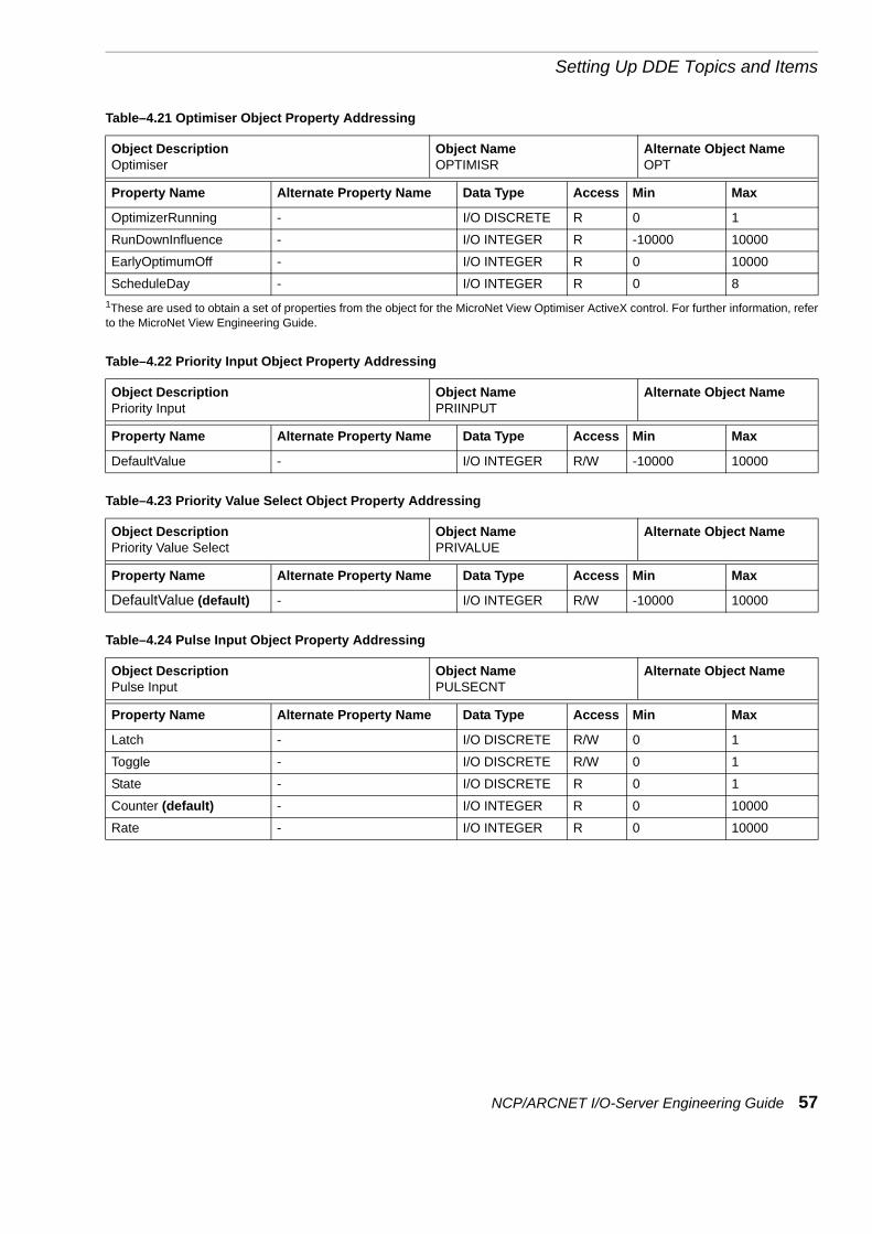
Setting Up DDE Topics and Items
OptimizerRunning - I/O DISCRETE R 0 1
RunDownInfluence - I/O INTEGER R -10000 10000
EarlyOptimumOff - I/O INTEGER R 0 10000
ScheduleDay - I/O INTEGER R 0 81These are used to obtain a set of properties from the object for the MicroNet View Optimiser ActiveX control. For further information, referto the MicroNet View Engineering Guide.
Table–4.22 Priority Input Object Property Addressing
Object DescriptionPriority Input
Object NamePRIINPUT
Alternate Object Name
Property Name Alternate Property Name Data Type Access Min Max
DefaultValue - I/O INTEGER R/W -10000 10000
Table–4.23 Priority Value Select Object Property Addressing
Object DescriptionPriority Value Select
Object NamePRIVALUE
Alternate Object Name
Property Name Alternate Property Name Data Type Access Min Max
DefaultValue (default) - I/O INTEGER R/W -10000 10000
Table–4.24 Pulse Input Object Property Addressing
Object DescriptionPulse Input
Object NamePULSECNT
Alternate Object Name
Property Name Alternate Property Name Data Type Access Min Max
Latch - I/O DISCRETE R/W 0 1
Toggle - I/O DISCRETE R/W 0 1
State - I/O DISCRETE R 0 1
Counter (default) - I/O INTEGER R 0 10000
Rate - I/O INTEGER R 0 10000
Table–4.21 Optimiser Object Property Addressing
Object DescriptionOptimiser
Object NameOPTIMISR
Alternate Object NameOPT
Property Name Alternate Property Name Data Type Access Min Max
NCP/ARCNET I/O-Server Engineering Guide 57

Chapter 4
Table–4.25 Pulse Pair Object Property Addressing
Object DescriptionPulse Pair
Object NamePULSPAIR
Alternate Object NamePP
Property Name Alternate Property Name Data Type Access Min Max
StrokeTime MAX_STROKE_TIME I/O INTEGER R/W 1 10000
RunOnTimeout RUN_ON_TIME I/O INTEGER R/W 0 10000
Action - I/O INTEGER R 01 41
CurrentPosition (default) APPROX_POSITION (default)
I/O INTEGER R 0 100
CurrentRunTime APPROX_RUN_TIME I/O INTEGER R 0 100001The values are: 0 = Stopped; 1 = Decrementing; 2 = Incrementing; 3 = At Min; 4 = At Max.
Table–4.26 Pulse Width Modulation (PWM) Object Property Addressing
Object DescriptionPulse Width Modulation (PWM)
Object NamePULSWDMO
Alternate Object NamePWM
Property Name Alternate Property Name Data Type Access Min Max
Period (default) PWM_PERIOD (default) I/O INTEGER R/W 1 10000
Table–4.27 Rate Limiter Object Property Addressing
Object DescriptionRate Limiter
Object NameRATELIMI
Alternate Object NameRATE
Property Name Alternate Property Name Data Type Access Min Max
Deviation (default) - I/O INTEGER R/W 0 10000
TimeConstant TIME_CONSTANT I/O INTEGER R/W 0 10000
Table–4.28 Rotation Object Property Addressing
Object DescriptionRotation
Object NameROTATE
Alternate Object NameROT
Property Name Alternate Property Name Data Type Access Min Max
ManualRotation MANUAL_ROTATE I/O DISCRETE R/W 0 1
LeadPoint LEAD_POINT I/O INTEGER R 0 5
Table–4.29 Scaler Object Property Addressing
Object DescriptionScaler
Object NameSCALER
Alternate Object NameSCALE
Property Name Alternate Property Name Data Type Access Min Max
InputMinimum INPUT_MINIMUM I/O INTEGER R/W -10000 10000
InputMaximum INPUT_MAXIMUM I/O INTEGER R/W -10000 10000
OutputMinimum OUTPUT_MINIMUM I/O INTEGER R/W -10000 10000
OutputMaximum OUTPUT_MAXIMUM I/O INTEGER R/W -10000 10000
58 NCP/ARCNET I/O-Server Engineering Guide

Setting Up DDE Topics and Items
Table–4.30 S-Link Object Property Addressing
Object DescriptionS-Link
Object NameSLINK
Alternate Object Name
Property Name Alternate Property Name Data Type Access Min Max
Units - I/O DISCRETE R/W 0 1
OverTime - I/O INTEGER R/W 0 99
DownloadSettings - I/O DISCRETE R/W 0 1
ComfortSP - I/O INTEGER R/W -10000 10000
HeatSP - I/O INTEGER R/W -10000 10000
CoolSP - I/O INTEGER R/W -10000 10000
Value (default) - I/O INTEGER R -10000 10000
Table–4.31 Step Driver Object Property Addressing
Object DescriptionStep Driver
Object NameSTEPDRIV
Alternate Object NameSTEP
Property Name Alternate Property Name Data Type Access Min Max
Step1Threshold STEP_THRESHOLD_1 I/O INTEGER R/W -10000 10000
Step2Threshold STEP_THRESHOLD_2 I/O INTEGER R/W -10000 10000
Step3Threshold STEP_THRESHOLD_3 I/O INTEGER R/W -10000 10000
Step4Threshold STEP_THRESHOLD_4 I/O INTEGER R/W -10000 10000
Step5Threshold STEP_THRESHOLD_5 I/O INTEGER R/W -10000 10000
Step6Threshold STEP_THRESHOLD_6 I/O INTEGER R/W -10000 10000
StepHysteresis STEP_HYSTERESIS I/O INTEGER R/W -10000 10000
Table–4.32 Stopwatch Object Property Addressing
Object DescriptionStopwatch
Object NameSTOPWTCH
Alternate Object NameSTOP
Property Name Alternate Property Name Data Type Access Min Max
TimeUnits TIME_UNITS I/O INTEGER R/W 01 31
CurrentCount (default) CURRENT_COUNT (default) I/O INTEGER R/W 0 10000
Rollover - I/O INTEGER R/W 0 100001The values are: 0 = Seconds; 1 = Minutes; 2 = Hours; 3 = Days.
NCP/ARCNET I/O-Server Engineering Guide 59

Chapter 4
Table–4.33 System Object Property Addressing
Object DescriptionSystem
Object NameSYSTEM
Alternate Object Name
Property Name Alternate Property Name Data Type Access Min Max
DetectorSpeed - I/O DISCRETE R/W 0 1
FlashRate - I/O INTEGER R/W 0 100
AlarmPresent - I/O DISCRETE R 0 1
LogFull - I/O DISCRETE R 0 1
NullOutputs - I/O DISCRETE R/W 0 1
Table–4.34 Threshold Object Property Addressing
Object DescriptionThreshold
Object NameTHRESHLD
Alternate Object NameTHRES
Property Name Alternate Property Name Data Type Access Min Max
OnThreshold ON_THRESHOLD I/O INTEGER R/W -10000 10000
OffThreshold OFF_THRESHOLD I/O INTEGER R/W -10000 10000
Table–4.35 Time Schedule Object Property Addressing
Object DescriptionTime Schedule
Object NameTIMESCH
Alternate Object NameSCH
Property Name Alternate Property Name Data Type Access Min Max
CtrlData1 (default) - I/O MESSAGE R/W N/A N/A
MonSwitch1On - I/O INTEGER R/W 0 2359
MonSwitch2On - I/O INTEGER R/W 0 2359
MonSwitch3On - I/O INTEGER R/W 0 2359
MonSwitch4On - I/O INTEGER R/W 0 2359
TueSwitch1On - I/O INTEGER R/W 0 2359
TueSwitch2On - I/O INTEGER R/W 0 2359
TueSwitch3On - I/O INTEGER R/W 0 2359
TueSwitch4On - I/O INTEGER R/W 0 2359
WedSwitch1On - I/O INTEGER R/W 0 2359
WedSwitch2On - I/O INTEGER R/W 0 2359
WedSwitch3On - I/O INTEGER R/W 0 2359
WedSwitch4On - I/O INTEGER R/W 0 2359
ThuSwitch1On - I/O INTEGER R/W 0 2359
ThuSwitch2On - I/O INTEGER R/W 0 2359
ThuSwitch3On - I/O INTEGER R/W 0 2359
ThuSwitch4On - I/O INTEGER R/W 0 2359
FriSwitch1On - I/O INTEGER R/W 0 2359
FriSwitch2On - I/O INTEGER R/W 0 2359
FriSwitch3On - I/O INTEGER R/W 0 2359
FriSwitch4On - I/O INTEGER R/W 0 2359
60 NCP/ARCNET I/O-Server Engineering Guide

Setting Up DDE Topics and Items
SatSwitch1On - I/O INTEGER R/W 0 2359
SatSwitch2On - I/O INTEGER R/W 0 2359
SatSwitch3On - I/O INTEGER R/W 0 2359
SatSwitch4On - I/O INTEGER R/W 0 2359
SunSwitch1On - I/O INTEGER R/W 0 2359
SunSwitch2On - I/O INTEGER R/W 0 2359
SunSwitch3On - I/O INTEGER R/W 0 2359
SunSwitch4On - I/O INTEGER R/W 0 23591This is used to obtain a set of properties from the object for the MicroNet View Time Schedule ActiveX control. For further information, referto the MicroNet View Engineering Guide.
Table–4.36 Universal Input (Configurable Input) Object Property Addressing
Object DescriptionUniversal Input (Configurable Input)
Object NameCFGINPUT
Alternate Object NameC
Property Name Alternate Property Name Data Type Access Min Max
Units - I/O INTEGER R/W 01 41
Value (default) - I/O INTEGER R -40 10000
Latch - I/O DISCRETE R/W 0 1
Toggle - I/O DISCRETE R/W 0 1
State - I/O DISCRETE R 0 11The values are: 0 = C; 1 = F; 2 = Ohms; 3 = Lux; 4=0-100.
Table–4.35 Time Schedule Object Property Addressing
Object DescriptionTime Schedule
Object NameTIMESCH
Alternate Object NameSCH
Property Name Alternate Property Name Data Type Access Min Max
NCP/ARCNET I/O-Server Engineering Guide 61

Chapter 4
Addressing Properties Using Table and Offset Values
If you wish to set up a DDE item to address a property in a controller but cannot use the property name format (see page 49), you can use the following format instead:
<Subnet>/<Node>/<PropAdd>
Where <PropAdd> is:
<Table>,<Offset>,<Type>[,<Ident>]
Warning: Writing an out-of-range value to a controller will cause it to reload default parameter values, suspend all control logic processing and set outputs to zero either during operation or when power is re-applied.
Where:
• <Subnet> and <Node> specify the address of the controller. See page 49.
• <Table> and <Offset> specify the table and offset values of the property within the controller’s memory. For all but the UniFACT PRO controllers, call your local sales office for details of the values to enter.
• <Type> specifies the property type, where:
• <Ident> specifies additional information when <type> is 5, 8 or 10 (as described above).
1 = Two-byte integer with sign (I/O INTEGER).2 = Two-byte BCD; used for time values (I/O INTEGER).3 = One-byte integer with sign (I/O INTEGER).4 = One-byte BCD (I/O INTEGER).5 = Buffer with fixed size1 (I/O MESSAGE).6 = Three-byte floating point value (I/O REAL).7 = Time value as an integer 0 to 23592 (I/O INTEGER)8 = Logged value from controller3
9 Unsigned byte (I/O INTEGER)10 Bit value4. The result is I/O DISCRETE if the value of only one bit is
returned, or I/O INTEGER if the value of more than one bit is returned.
11 Two-byte unsigned (I/O INTEGER).1When using conversion type 5, use <Ident> to specify the number of bytes to readfrom the controller.2Therefore a time of, for example, 16:59 is returned as the integer 1659.3Logged values are formatted according to <Ident>, which is a value in the range 1to 4, as shown in Table–4.37. Note that this gives access to logged data in a Loggingobject in the controller; it does not give access to the logging capabilities of theMNMI, as set up by the MicroNet View Monitor Tool.4When using conversion type 10, use <ident> to specify the bit(s) to access byspecifying a mask as shown in Table–4.38. <Ident> can be expressed as a decimalor hex value. A hex value must be preceeded by 0x. For values that use several bits(such as fan speed), add the masks for the bits involved.
62 NCP/ARCNET I/O-Server Engineering Guide

Setting Up DDE Topics and Items
Addressing Examples
Example 1: A DDE item of 1/2/114,2,1 specifies that you want to access the property in table table 114 at offset 2. The property is a two-byte integer, with sign. The property belongs to the controller with a subnet address of 1 and a node address of 2.
Example 2: A DDE item of of 1/33/114,58,1 specifies that you want to access the property in table 114 at offset 58. The property is a two-byte integer, with sign. The property belongs to the controller with a subnet address of 1 and a node address of 33.
Table–4.37 <Ident> Values for Type 8 (Logged Data)
<Ident> Type Meaning1 I/O
MESSAGETime of logging, logged status value and logged analogue value written as DD/MM HH:NN:SS ST AN, where:DD is the day in month (1-31).MM is the month of year 01-12.HH is the hour 00-23.NN are the minutes 00-59.SS are the seconds 00-59.ST is the state input value of 0, 1 or -1 (not active).AN is the analogue input value or -1.0 (not active).
2 I/O MESSAGE
Time of logging written as DD/MM HH:NN:SS, where:DD is the day in month (1-31).MM is the month of year 01-12.HH is the hour 00-23.NN are the minutes 00-59.SS are the seconds 00-59.
3 I/O INTEGER
The logged status input as an integer. If no value has been logged (a not active state existed at the input), the value of -1 is returned.
4 I/O REAL The logged analogue input as a real number. If no value has been logged (a not active state existed at the input), the value of -1.0 is returned.
Table–4.38 <Ident> Values for Type 10 (Bit Values)
Bit <Ident> (Decimal) <Ident> (Hex)7 128 0x806 64 0x405 32 0x204 16 0x103 8 0x082 4 0x041 2 0x020 1 0x01
NCP/ARCNET I/O-Server Engineering Guide 63

Chapter 4
Example 3: A DDE item of 10/1/102,0,5,56 specifies that you want to access the property in table 102 at offset 0. The property is of type I/O MESSAGE, and 56 bytes are to be read. The property belongs to the controller with a subnet address of 10 and a node address of 1.
Example 4: A DDE item of 11/1/51,28,10,128 specifies that you want to access a property in table 51 at offset 28. The property is a bit value (type 10), and bit 7 (decimal 128) is to be read. The property belongs to the controller with a subnet address of 11 and a node address of 1.
Note: Refer to the UniFACT PRO Engineering Data Sheet (DS 13.303.A) for details of the UniFACT PRO controller properties.
Note: For UniFACT PRO controllers that have version 1.xx firmware, it is important that the poll scheme is set up to prevent the I/O-Server from performing real-time clock updates (see page 27).
Addressing Properties in UniFACT PRO controllers
Table–4.39 Table and Offsets for UniFACT PRO Controllers
Description <Type> <PropAdd> Access Min Max
Version (same as table 50, offset 0). 5 4,0,5,6 R - -
Version. This is a 6-character (6-byte) string. 5 50,0,5,6 R - -
SLink Present (bit 7). 10 50,6,10,128 R 0 1
T-Type Present (bit 3). 10 50,6,10,8 R 0 1
H/W Override (bit 2). 10 50,6,10,4 R 0 1
Sensor Temperature (in °C multiplied by 10). 11 50,7,11 R 0 400
Firmware Build (firmware version number). 11 50,9,11 R 0 32767
Control Loop Mode (bits 0 to 2):0 = Comfort1 = Economy2 = Night3 = Frost Protection4 = Fire Override
10 50,11,10,7 R 0 4
Initialisation Mode (bit 7). 10 50,11,10,128 R 0 1
S-Link Auto/Manual Flag (bit 7). 10 50,12,10,128 R 0 1
Fan Speed (bits 1 and 0). 10 50,12,10,3 R 0 3
Loop output (percentage). 9 50,13,9 R 0 100
Range Check Error (bit 0 - available only for firmware version 2.0 or later).
10 50,14,10,1 R 0 1
Range Check Errors Table (available only for firmware version 2.0 or later).
9 50,15,9 R 0 255
Range Check Errors Offset (available only for firmware version 2.0 or later).
9 50,16,9 R 0 255
Subnet address of controller. 9 51,0,9 R/W 1 255
Node address of controller. 9 51,1,9 R/W 1 127
H/W Ovr Timer (in seconds). 11 51,2,11 R/W 0 600
PWM Cycle Time (in seconds). 11 51,4,11 R/W 1 600
64 NCP/ARCNET I/O-Server Engineering Guide

Setting Up DDE Topics and Items
Pulsed-Pair Stroke Time (in seconds). 11 51,6,11 R/W 1 600
Comfort SP (in °C multiplied by 10). 11 51,8,11 R/W 150 300
Economy SP - Heating (in °C multiplied by 10). 11 51,10,11 R/W 100 240
Economy SP - Cooling (in °C multiplied by 10). 11 51,12,11 R/W 210 350
Frost SP (in °C multiplied by 10). 11 51,14,11 R/W 0 150
Differential 1 (in °C multiplied by 10). 9 51,16,9 R/W 5 35
Differential 2 (percentage). 9 51,17,9 R/W 0 100
Controller Action. 9 51,18,9 R 0 1
Comfort Tolerance (in °C multiplied by 10). 9 51,19,9 R/W 0 40
Proportional Band (in °C). 9 51,20,9 R/W 1 99
Integral Time (in seconds divided by 20). 9 51,21,9 R/W 0 250
Output Limit (percentage). 9 51,22,9 R/W 0 100
Valve Pos Override (bits 0 to 6). 10 51,23,10,127 R/W 0 100
Override Enable (bit 7). 10 51,23,10,128 R/W 0 1
Fan Speed Operation (must be either 1 or 3; a value of 2 is not permitted).
9 51,24,9 R/W 1 3
Fan Turn-Off Delay (in mins multiplied by 10). 9 51,25,9 R/W 0 100
S-Link Override Time. 9 51,26,9 R/W 0 99
Heater Installed (bit 7). 10 51,27,10,128 R/W 0 1
Heater Configuration (bit 6). 10 51,27,10,64 R/W 0 1
Heater Active (bit 5). 10 51,27,10,32 R 0 1
DX Cooling Active (bit 4). 10 51,27,10,16 R 0 1
Controller Mode (bit 3). 10 51,27,10,8 R 0 1
Thermostat Status (bit 2). 10 51,27,10,4 R 0 1
Preferred Temperature Source (bit 1). 10 51,27,10,2 R/W 0 1
Controller Mode Override (bit 0). 10 51,27,10,1 R/W 0 1
Override to Fire Mode (bit 7). 10 51,28,10,128 R/W 0 1
Override to Economy Mode (bit 6). 10 51,28,10,64 R/W 0 1
Override to Night Mode (bit 5). 10 51,28,10,32 R/W 0 1
Frost Protection Active (bit 4). 10 51,28,10,16 R 0 1
Start Valve/Fan Exercise (bit 3) (network set). Bit 3 is automatically reset when the exercise is complete or if the mode cannot be started.)
10 51,28,10,8 R/W 0 1
Free Cooling Active (bit 2). 10 51,28,10,4 R/W 0 1
H/W Input Overrides to Night Mode (bit 1). 10 51,28,10,2 R/W 0 1
H/W Input is Enabled (bit 0). 10 51,28,10,1 R/W 0 1
Actuator Type (bit 7). 10 51,29,10,128 R/W 0 1
DUS Sensor Attached (bit 6). 10 51,29,10,64 R/W 0 1
Fan Enabled in Comfort Mode (bit 5). 10 51,29,10,32 R/W 0 1
S-Link PSlave Mode (bit 4 - available only for firmware version 2.0 or later).
10 51,29,10,16 R/W 0 1
Frost Protection Enabled (bit 3). 10 51,29,10,8 R/W 0 1
Table–4.39 Table and Offsets for UniFACT PRO Controllers
Description <Type> <PropAdd> Access Min Max
NCP/ARCNET I/O-Server Engineering Guide 65

Chapter 4
Heater Override to On (bit 2). 10 51,29,10,4 R/W 0 1
DX Cooling Override to On (bit 1). 10 51,29,10,2 R/W 0 1
Zero Delay H/W Input is Enabled (bit 0). 10 51,29,10,1 R/W 0 1
Reset Count. 9 52,1,9 R/W 0 255
Unit Name. This is a 12-character (12-byte) string. 5 52,3,5,12 R/W - -
Setpoint Adjustment (in °C multiplied by 10). 3 52,15,3 R/W -30 30
Do Fan/Actuator Exercise. Setting to 172 causes a reset. Only this value has any effect.
9 52,27,9 R/W 0 172
Differential 3 (in °C multiplied by 10). 9 52,28,9 R/W 5 30
Fan Timer (in seconds). 11 53,0,11 R 0 600
Overrun Timer (in seconds). 11 53,2,11 R 0 60
H/W Override Timer (in seconds). 11 53,4,11 R 0 600
Free Cooling Timer (in seconds). 11 53,6,11 R 0 3600
Cooling Actuator Pos or Damper Pos (percentage). 9 54,0,9 R 0 100
Heating Actuator Pos (percentage). 9 54,1,9 R 0 100
Cooling Actuator Op or Damper Op. Valid values are:0 = Stopped or1 = Decrementing or2 = Incrementing (pulsed-pair only) or64 = Decrementing (PWM only) or130 = Stopped (PWM only)
9 54,2,9 R 0 130
Heating Actuator Op. Valid values are:0 = Stopped or1 = Decrementing or2 = Incrementing (pulsed-pair only) or64 = Decrementing (PWM only) or130 = Stopped (PWM only)
9 54,3,9 R 0 130
Flash Updates. 11 55,0,11 R 0 65535
Cycle Time. 11 55,2,11 R 0 65535
Current Time - Seconds Value. All properties in table 69 are available only for firmware version 2.0 or later.
9 69,0,9 R/W 0 59
Current Time - Minutes Value. 9 69,1,9 R/W 0 59
Current Time - Hours Value. 9 69,2,9 R/W 0 59
Current Weekday. 9 69,3,9 R/W 1 7
Current Date - Day Value. 9 69,4,9 R/W 1 31
Current Week. 9 69,5,9 R/W 0 52
Current Date - Month Value. 9 69,6,9 R/W 1 12
Current Date - Year Value. 9 69,7,9 R/W 0 99
Current Date - Real Year Value. 11 69,9,11 R/W 0 65535
Table–4.39 Table and Offsets for UniFACT PRO Controllers
Description <Type> <PropAdd> Access Min Max
66 NCP/ARCNET I/O-Server Engineering Guide

Setting Up DDE Topics and Items
DDE Items for Controller Status Information
If you wish to obtain status information about the communications link to a controller, use the following DDE item format:
<Subnet>/<Node>/<Comms Info>
Where:
• <Subnet> and <Node> specify the address of the controller. See page 49.
• <Comms Info> can be one of the values shown in Table–4.40. Note that all the data is read-only.
Addressing Example
A DDE item of 1/2/COMMS-ERRORS specifies that you want to obtain communications error rate from the controller with a subnet address of 1 and a node address of 2.
Table–4.40 <Comms Info> Values
<Comms Info> Meaning Type Access Min MaxACTIVE-ITEMS Returns the number of active DDE items (see page
48) for the specified controller.I/O INTEGER R - -
COMMS-DEAD Returns 1 if the controller has not replied to the last 15 communications requests, otherwise returns 0. A controller with a COMMS-DEAD status of 1 is polled less frequently than other controllers (every 5 minutes).
I/O DISCRETE R 0 1
COMMS-ERRORS Returns (as a percentage value) the error rate of the communications link to the controller measured in the last 50 communications requests. An error is generated if the controller does not reply within the specified time-out period, or if the controller replies but the reply contains errors.
I/O INTEGER R 0 100
COMMS-ONLINE Indicates whether the controller is online or offline. Returns a value of 1 if the controller is online, or 0 if it is offline. A controller is considered offline if it has not replied properly in the last five communications requests.
I/O DISCRETE R 0 1
REPLY-TIME Returns the time in milliseconds that the last communication to the controller took to complete. The time returned is from the point at which the DDE requested information to the point at which the reply was fully received. This can be used to identify faulty or overloaded controllers on a network.
I/O INTEGER R - -
NCP/ARCNET I/O-Server Engineering Guide 67

Chapter 4
DDE Items for Poll Scheme Information and Manual Scans
The DDE items shown in Table–4.41 enable you to obtain information about a poll scheme or to force a polling scan from your front-end application.
Note: The DDE topic specifies the site and poll scheme to access.
Table–4.41 Item Values to Obtain Poll Scheme Status Information
DDE Item Meaning Type Access Min MaxACTIVE-ITEMS Returns the number of active DDE items (see page
48) for all controllers accessed through the poll scheme.
I/O INTEGER R - -
COMMS-ERRORS Returns (as a percentage value) the error rate of the communications link to the controllers access via the poll scheme, measured in the last 50 communications requests. An error is generated if the controller does not reply within the specified time-out period, or if the controller replies but the reply contains errors.
I/O INTEGER R 0 100
LAST-SCAN Returns the time in milliseconds for the last complete scan through all the controllers to retrieve values for all the active DDE items (see page 48) accessed via the poll scheme.
I/O INTEGER R - -
RETIME-NOW When set to 1, the I/O-Server retimes all controllers in the poll scheme.
I/O DISCRETE R/W 0 1
SCAN-NOW When set to 1, the I/O-Server forces a read of all the controllers accessed via the poll scheme. This can be used to implement an Update Now button in WindowViewer.
I/O DISCRETE R/W 0 1
THIS-SCAN Returns the time in milliseconds to scan through all the controllers to retrieve values for all the active DDE items (see page 48) accessed via the poll scheme. The value is updated as the current scan progresses.
I/O INTEGER R - -
68 NCP/ARCNET I/O-Server Engineering Guide

Setting Up DDE Topics and Items
DDE Items for Site Status/Control
The DDE items shown in Table–4.42 enable you to obtain runtime status information about an entire site and to perform various site control functions.
DDE Items for site status/control must use a DDE topic of the form <site>/STATUS, as described on page 46.
Table–4.42 Item Values to Obtain Site Status Information
DDE Item Meaning Type Access Min MaxACTIVE-ITEMS Returns the total number of active DDE items (see
page 48) for the site. Only those DDE items used to obtain data in a controller are included in the count (i.e. site status and poll-scheme status tags are not included).
I/O INTEGER R - -
COMMS-ERRORS Returns (as a percentage value) the average error rate of the communications link to the controllers accessed via any poll scheme to the site, measured in the last 50 communications requests. An error is generated if a controller does not reply within the specified time-out period, or if a controller replies but the reply contains errors.
I/O INTEGER R 0 100
CONNECT-NOW When this is assigned a value of 1, the I/O-Server will dial the remote site as if a new item had been activated on that site. This is similar to selecting Connect to Remote Site in the Manual menu of the I/O-Server.
I/O DISCRETE W - -
CONNECT-STATUS Returns a value that indicates that connection status of the I/O-Server to the site. A value greater than 0 indicates that the I/O-Server is connected. A value less than or equal to 0 indicates that the I/O-Server is not connected. The possible values are as follows:-1 The I/O-Server is waiting for a modem to become
available from the modem pool (remote site only).-2 The I/O-Server is dialling the site (remote site
only).0 The I/O-Server is not connected to the site.1 The I/O-Server is performing a login to the site
(remote site only).2 The I/O-Server is collecting alarms and/or loggings
from the site (remote site only).3 The I/O-Server is disconnecting from the site
(remote site only).4 The I/O-Server is connected to the site.
I/O INTEGER R -2 4
CONNECT-TIME Returns the total time in seconds connected to the site since midnight. The value is reset if you close and restart the I/O-Server or you select File, Reset.
I/O INTEGER R - -
DISCONNECT-NOW When this is assigned a value of 1, the I/O-Server will terminate the connection with the remote site, if currently connected. This is similar to selecting Disconnect From Remote Site in the Manual menu of the I/O-Server.
I/O DISCRETE W - -
NCP/ARCNET I/O-Server Engineering Guide 69

Chapter 4
DISCONNECT-TIMER Returns the time in seconds that the communications link to the remote site will remain open. The communications link will be disconnected if no new data is requested from the front-end, e.g. WindowViewer. Each time new data is requested, the timer resets to the value specified in the remote site’s Disconnect after property, as set in the I/O-Server.
I/O INTEGER R - -
DOWNLOAD-BASIC When this is assigned a value of 1, the I/O-Server will download the basic configuration to the MNMI. This is similar to selecting Send Basic Configuration to the MNMI in the Manual menu of the I/O-Server.
I/O DISCRETE W - -
DOWNLOAD-POLLS When this is assigned a value of 1, the I/O-Server will download the alarm and logging configuration to the MNMI. This is similar to selecting Send Alarm and Logging Configuration to the MNMI in the Manual menu of the I/O-Server.
I/O DISCRETE W - -
PENDING-READS Returns the number of active DDE items (see page 48) whose values have not yet been read from the controller.
I/O INTEGER R - -
PENDING-WRITES Returns the number of DDE items that have been assigned a new value, but have not yet been written to the controller.
I/O INTEGER R - -
RECONFIGURE-ALL When this is assigned a value of 1, the I/O-Server will perform a complete reconfiguration of the MNMI. This is similar to selecting Reconfigure MNMI and Resynchronise in the Manual menu of the I/O-Server.
I/O DISCRETE W - -
RECONNECT-TIMER Returns the time in seconds to the next connection to the remote site to refresh controller property or status values in the front-end. Note that the timer is maintained only if DDE items used to obtain controller data are active (see page 48) for the site. If no DDE items are active, no reconnection will occur.DDE items used to obtain site status and poll-scheme status information have no effect on the timer.
I/O INTEGER R - -
UPLOAD-POLLS When this is assigned a value of 1, the I/O-Server will retrieve the current state of alarms and logged data from the MNMI. This is similar to selecting Read Current Alarms and Loggings from the MNMI in the Manual menu of the I/O-Server.
I/O DISCRETE W - -
Table–4.42 Item Values to Obtain Site Status Information
DDE Item Meaning Type Access Min Max
70 NCP/ARCNET I/O-Server Engineering Guide

Setting Up DDE Topics and Items
Setting Up Tags in WindowMaker
If you are using MicroNet View WindowMaker, you can set up DDE items by defining tags in the tagname dictionary.
You cannot design your WindowViewer runtime interface (i.e. the screens in which to view information from controllers) or set up alarm limits in the Monitor Tool until the tags are defined in the tagname dictionary.
Note: You can set up access names and tags for controller properties automatically (see page 45).
If you wish to view, modify or create a tag:
1. Open the Tagname Dictionary using WindowMaker.A dialogue box similar to the following is displayed:
2. Select New or Select (to modify an existing tag), then set up and save the details of the tag. Make sure that you set up the following options (leave the remaining options at their default values).
TagnameSpecify a unique and legal tag name.
TypeThe tag Type must correspond to the type of the controller property you wish to access, as shown in Table–4.1 to Table–4.42. Complete the Item option first, so that you can understand which table and type to use.
Read only/ReadWriteChoose ReadWrite only if you require the data to be editable from WindowViewer. Some data cannot be edited from WindowViewer, even if you select ReadWrite (see Table–4.1 to Table–4.42).
NCP/ARCNET I/O-Server Engineering Guide 71

Chapter 4
Access NameSelect the appropriate access name (see page 46).
ItemSpecify the DDE item.
72 NCP/ARCNET I/O-Server Engineering Guide
Appendix AError Messages
IntroductionDuring runtime, the I/O-Server may show error messages in the Error Messages List in the I/O-Server window. If the MicroNet View InTouch WWLogger is running, the error messages are logged within the WWLogger as well.
The error messages are grouped into three major groups: fatal errors, critical errors and normal errors.
Fatal errors indicate that the PC-system is in an unstable state and should be restarted as soon as possible.
Critical errors are probably due to an incorrect configuration of either the I/O-Server or the application using the I/O-Server to communicate with the controllers.
Normal errors are errors that may occur even in a properly configured system. Most of these are due to communication problems with the modem, the remote MNMI or the controllers.
Fatal System ErrorsMessage Invalid site pointer XXXX:XXXX in LocalSiteThread
Invalid site pointer XXXX:XXXX in RemoteSiteThread
Cause The I/O-Server application has detected that some of the internal I/O-Server memory has been corrupted, either by the I/O-Server itself or by another application.
Action Terminate all running applications and reboot the system. If the problem persists, please contact TAC Satchwell.
Message Unable to allocate memory for device object
Not enough memory to create item <name>
Unable to allocate memory for buffer in controller read
Unable to allocate memory for buffer in controller write
NCP/ARCNET I/O-Server Engineering Guide 73

Appendix A
Cause The I/O-Server is not able to dynamically allocate memory from Windows. Since all versions of Windows uses a swap file to give access to more memory than has physically been installed in the PC, you will most likely only get this message if some of the Windows system memory has been corrupted causing the Windows memory manager to fail.
Action Terminate all running application and reboot the system. If the problem persists, please contact TAC Satchwell.
Fatal DDE ErrorsMessage Can not create topic <name> - already processing DDE
message
Unable to delete topic <name> - already processing DDE message
Unable to create item <name> - already processing DDE message
Unable to delete item <name> - already processing DDE message
Unable to activate item <name> - already processing DDE message
Unable to deactivate item <name> - already processing DDE message
Unable to set item value for item <name> - already processing DDE message
Cause The I/O-Server is only able to process one DDE message at a time, where a DDE message is some of the internals used when passing data between applications via DDE. This error message indicates that the I/O-Server has received another DDE message before it was done processing the current DDE message.
Action Terminate all running applications and reboot the system. If the problem persists, please contact TAC Satchwell.
Message Unable to delete topic - invalid topic pointer XXXX:XXXX passed to driver
Unable to create item - invalid topic pointer XXXX:XXXX passed to driver
Unable to delete item - invalid topic pointer XXXX:XXXX passed to driver
Unable to delete item - invalid item pointer XXXX:XXXX passed to driver
74 NCP/ARCNET I/O-Server Engineering Guide
Error Messages
Unable to activate item - invalid topic pointer XXXX:XXXX passed to driver
Unable to activate item - invalid item pointer XXXX:XXXX passed to driver
Unable to deactivate item - invalid topic pointer XXXX:XXXX passed to driver
Unable to deactivate item - invalid item pointer XXXX:XXXX passed to driver
Unable to set item value - invalid topic pointer XXXX:XXXX passed to driver
Unable to set item value - invalid item pointer XXXX:XXXX passed to driver
Cause Some of the data passed to the I/O-Server as part of the internal DDE messaging is not valid. This may be due to the internal I/O-Server memory being corrupted, either by the I/O-Server itself or by another application.
Action Terminate all running applications and reboot the system. If the problem persists, please contact TAC Satchwell.
Critical Communication ErrorsMessage Unable to open device <port>
Cause The I/O-Server is unable to access the specified port either because the port does not exist or the port is already in use by another application.
Action Verify that the port is valid and not in use by another application such as pcANYWHERE.
Message Unable to start site - no serial device <port> configured
Cause The serial port selected under configuration of the site has not been configured under the Comms folder.
Action Configure the port under the Comms folder, or edit the site properties and select a configured port.
Message Unable to start site - serial device <port> already in use
Cause The serial port selected under configuration of the site has already been selected for another site. You must configure and select one separate port for each local site.
Action Edit the site properties and select another port for the site.
NCP/ARCNET I/O-Server Engineering Guide 75

Appendix A
Critical DDE ErrorsMessage Can not create DDE link - site in topic <name> is undefined
Cause An application is trying to create a DDE link to the I/O-Server where the site name in the DDE topic has not been configured under the Sites folder.
Action Check site spelling.
Message Can not create DDE link - poll in topic <site>/<poll scheme> not defined for this site
Cause An application is trying to create a DDE link to the I/O-Server where the poll scheme name in the DDE topic has not been configured for the site under the Sites folder.
Action Check poll scheme spelling.
Message Can't create item <name> - format must be <subnet>/<node>/...
Can't create item <name> - format must be <table>,<offset>,<format> or symbolic name
Cause An application is trying to create a DDE link to the I/O-Server where the DDE item name does not have the proper format.
Action Check item format.
Message Unable to create unknown status item <name>
Cause An application is trying to create a DDE link to the I/O-Server where the DDE item name is not one of the predefined status item names.
Action Check status item name.
Message Attempt to set item <name> to a value outside legal range
Cause An application is trying to set a DDE item to a value that is not legal for that type of item. To avoid controller memory being corrupted, the operation is rejected by the I/O-Server.
Action Check calling application.
Message Attempt to set value of read-only status item <name>
Cause An application is trying to set the value of a status item via DDE. Status items are read-only, so this is rejected by the I/O-Server.
Action Check calling application.
76 NCP/ARCNET I/O-Server Engineering Guide

Error Messages
Critical Remote Site ErrorsMessage No modem available for remote connection
Cause You are trying to access a remote site, but no modem has been configured under the Comms folder.
Action When working with remote sites, you must create at least one modem under the Comms folder. You may have multiple remote sites using the same modem though.
Message Unable to set local modem speed to <speed>
Cause The I/O-Server is not able to set the serial port speed to the setting defined in the modem configuration. The port speed should be set to one of 1200, 2400, 4800, 9600, 14400, 19200 or 38400.
Action Check that the port speed is set to one of the above. If the speed is set higher than 9600 also check that the serial port is based on a high speed UART 16550 or similar.
Message Unable to reset modem
Cause The modem does not reply OK to the reset command specified under the modem configuration.
Action Check that the configured reset command is valid for the attached modem.
Message Unable to initialize modem
Cause The modem does not reply OK to the initialise command specified under the modem configuration.
Action Check that the configured initialise command is valid for the attached modem.
Message Unable to get modem into command mode
Cause The I/O-Server can not get the modem to accept modem commands while being connected to the remote site.
Action Check that the configured back-to-command-mode command is valid for the attached modem.
Message Unable to disconnect from remote site
Cause The modem does not reply OK to the hang up command specified under the modem configuration.
Action Check that the configured hang-up command is valid for the attached modem.
NCP/ARCNET I/O-Server Engineering Guide 77

Appendix A
Message Unable to write password to remote MNMI
Cause The MNMI on the remote site does not accept the password specified in the properties for this site. The I/O-Server is not able to connect with this site.
Action Verify that the password specified in the site properties matches the password configured for the remote MNMI (use VisiSat to check the remote site password).
Remote Site ErrorsMessage Unable to dial remote site on <phone number>
Unable to connect to remote modem
Cause The I/O-Server is unable to establish a data connection to the modem on the remote site.
Action None unless it happens on a regular basis. In that case, the local modem, the remote modem and the telephone connection should be checked.
Message Unable to read version information from remote MNMI
Cause The I/O-Server is not able to read the firmware identifier from the remote MNMI. This is most probably due to a bad telephone connection.
Action None unless it happens on a regular basis. In that case, the local modem, the remote modem and the telephone connection should be checked.
Message Unable to read site code from remote MNMI
Cause The I/O-Server is unable to read the site code programmed into the remote site MNMI. This is most probably due to a bad telephone connection.
Action None unless it happens on a regular basis. In that case, the local modem, the remote modem and the telephone connection should be checked.
Message Carrier lost while reading (<table>, <offset>, <length>) from address <subnet>/<node>
Cause The connection to the remote site is lost while the I/O-Server is reading from the specified controller address. This is most probably due to a bad telephone connection.
Action None unless it happens on a regular basis. In that case, the local modem, the remote modem and the telephone connection should be checked.
78 NCP/ARCNET I/O-Server Engineering Guide

Error Messages
Message Carrier lost while writing (<table>, <offset>, <length>) to address <subnet>/<node>
Cause The connection to the remote site is lost while the I/O-Server is writing to the specified controller address. This is most probably due to a bad telephone connection.
Action None unless it happens on a regular basis. In that case, the local modem, the remote modem and the telephone connection should be checked.
Communication ErrorsMessage Unable to read (<table>, <offset>, <length>) from address
<subnet>/<node>
Cause The I/O-Server was not able to read data from the specified controller address, but it will retry the next time the controller is scanned.
Action None, but monitor the communication errors percentage for that controller. If it is significantly higher than the percentage for the other controllers in the network, it may indicate either a faulty controller or LAN connection.
Message Unable to write (<table>, <offset>, <length>) to address <subnet>/<node>
Cause The I/O-Server was not able to write data to the specified controller address.
Action None, but monitor the communication errors percentage for that controller. If it is significantly higher than the percentage for the other controllers in the network, it may indicate either a faulty controller or LAN connection.
Message Unable to update real time clock in address <subnet>/<node>
Cause The I/O-Server was not unable to write the current PC clock to the specified controller address. If the poll scheme has been configured to update the real time clock in the controllers, the I/O-Server will try to set the clock again in one hour.
Action None, but monitor the communication errors percentage for that controller. If it is significantly higher than the percentage for the other controllers in the network, it may indicate either a faulty controller or LAN connection.
NCP/ARCNET I/O-Server Engineering Guide 79

Appendix A
302487400_A3
80 NCP/ARCNET I/O-Server Engineering Guide


Copyright © 2005, TACAll brand names, trademarks and registered trademarksare the property of their respective owners. Informationcontained within this document is subject to changewithout notice. All rights reserved.
TAC HeadquartersMalmö, Sweden+46 40 38 68 50
Satchwell Helpline+44 (0) 1753 [email protected]
www.tac.com