navigat x mk 1 - telemar s.p.a yacht... · marine has created the navigat x mk 1 digital...
TRANSCRIPT
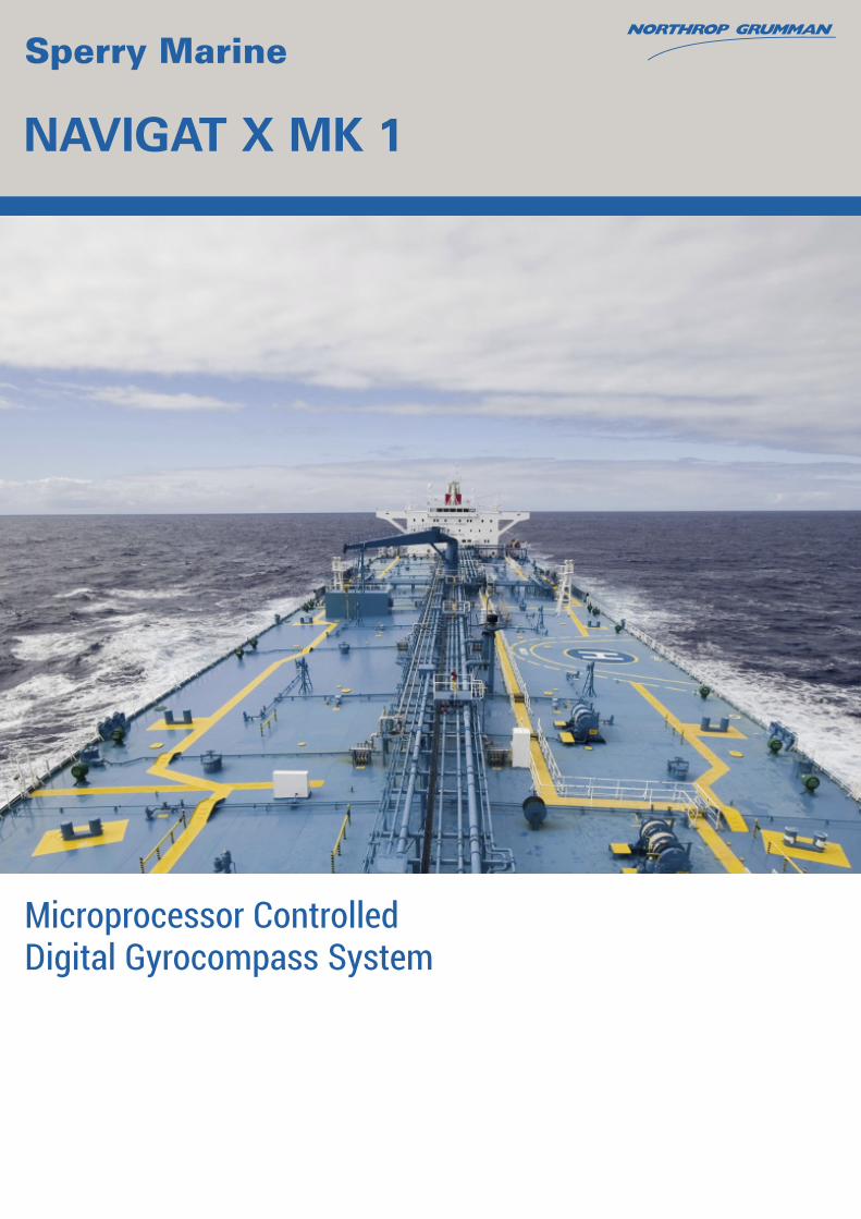
NAVIGAT X MK 1
Microprocessor Controlled Digital Gyrocompass System
Design and Standard Features System Configurations
OVERVIEW
With a watchful eye on the demands made on navigation and ship control technology emerging from the 21st
Century, Northrop Grumman Sperry Marine has created the NAVIGAT X MK 1 Digital Gyrocompass System. Ship’s cables are connected directly to terminals within the gyrocompass housing, greatly facilitating installation. All electronic components are plug-in modules, thus providing fast and easy service. Digital heading information is derived as an absolute value from a 13-bit shaft encoder. The NAVIGAT X MK 1 has a control and display unit installed in the front access cover. When required, the control and display unit can be removed from the access cover and installed at a location (e.g. bridge console) remote from the gyrocompass.
STANDARD FEATURES
•Comprises one single unit
•Control and display unit in front cover with 4-digit heading display and 6 operating keys
•Easy to install and easy to service
•High-speed follow-up system 100°/sec
•Type approved rate-of-turn output
•Automatic static north speed error correction
•Highly accurate digital heading data transmission by shaft encoder
•Self-synchronizing repeater compasses
•±180° electronic alignment error correction in setup program
•Will drive a maximum of 12 analogue repeaters
•180° heading offset function for shuttle vessels
•Automatic emergency power changeover and status alarm
•7 independent serial outputs RS 422, IEC 61162-1 and IEC 61162-2
•2 dependent 6 steps/° heading outputs (0.5 A)
•Complies with IMO regulations A.424(IX), A.694(17), A.821(19) - HSC (High Speed Craft) and ISO 8728.
•Outputs to Navigation Data Printer:
- Heading
- Heading source gyro/magnetic
- Rudder angles of two independent rudders
•Twin rotors and liquid damping system eliminates latitude error
•High Mean Time Between Failures (MTBF) of 40.000 hours and low power consumption
•All repeater compasses with serial interface
•Gyro system remains north stabilized during power interruptions of up to 3 minutes
•Single point suspension of the gyrosphere container eliminates the well-known adverse effects associated with gimbals.
•Monitoring and alarm functions for all voltages, gyroscope current and follow-up system (gyrosphere current, temperature, elapsed operation time)
The unique method of supporting the well-proven Sperry Marine gyrosphere by means of mere buoyancy ensures north stabilization during short power failures.
A special version, NAVIGAT X MK 1 HSC, is available to meet the demands of high-speed craft (HSC). Here, the unique centering pin retaining arrangement for the gyrosphere is mounted in an additional gimbal system, which allows the NAVIGAT X MK 1 Mod 7 gyrocompass an almost unlimited freedom of roll and pitch (±90°).
TYPE APPROVAL
NAVIGAT X MK 1 has been type approved by Germanischer Lloyd (GL) in accordance with the Marine Equipment Directive (MED) 96/98/EC (Wheelmark) and fulfills IMO Resolutions A.424(XI) and A.694(17) as well as IEC 61162.
The NAVIGAT X MK 1 HSC has been type approved to the High-Speed Craft Code by Germanischer Lloyd (GL) in accordance with the Marine Equipment Directive (MED) 96/98/EC (Wheelmark).
The rate-of-turn outputs of NAVIGAT X MK 1 and NAVIGAT X MK 1 HSC have been type approved by Germanischer Lloyd (GL) in accordance with the Marine Equipment Directive (MED) 96/98/EC (Wheelmark) and also fulfills IMO resolution A.526(13).
PERFORMANCE
Linear mean settle point error (RMS): ≤0.1° secant latitude
Static error (RMS): ≤0.1° secant latitude
Dynamic error (RMS): ≤ 0.4° secant latitude
Performance in accordance with IMO A.694(17), IMO A.821(19), ISO 8728 and ISO 16328(2001).
FREEDOM OF ROLL & PITCH
NAVIGAT X MK 1 Mod 7 ±90° NAVIGAT X MK 1 Mod 10 ±40°
POWER REQUIREMENTS
24 VDC (18 V to 36 V) and / or 115/230 VAC ± 10% 50 Hz / 60 Hz
The single-unit gyrocompass includes automatic swtichover to 24 V emergency power supply in accordance with GMDSS Rules.
OPERATIONAL DATA
Ambient temperature range Operation: -10°C to +55°C Storage: -25°C to +70°C (without supporting fluid)
Settling Time: < 3 hours Gyrocompass follow-up rate: 100°/sec Heading Display: digital with 4 digits
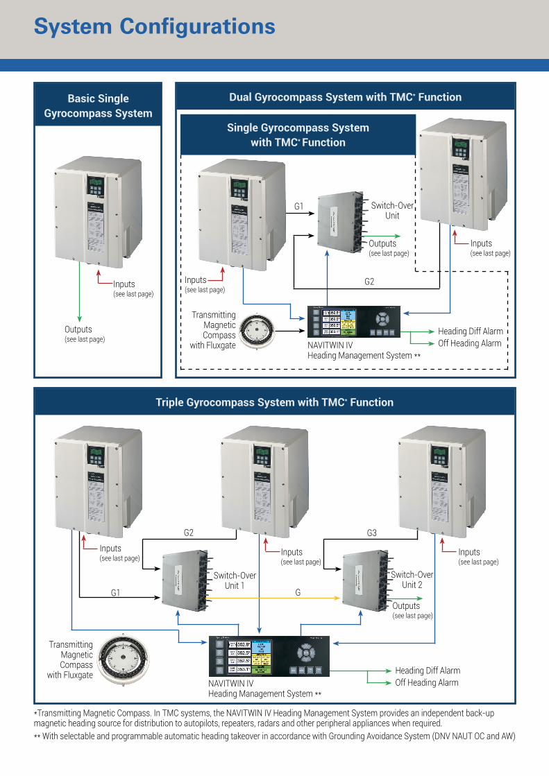
Triple Gyrocompass System with TMC* Function
Dual Gyrocompass System with TMC* Function
Inputs(see last page)
Basic Single Gyrocompass System
Design and Standard Features System Configurations
Single Gyrocompass System with TMC* Function
Inputs(see last page)
Inputs(see last page)
Outputs(see last page)
Inputs(see last page)
Inputs(see last page)
G1
Outputs(see last page)
Switch-OverUnit
Inputs(see last page)
TransmittingMagneticCompass
with Fluxgate
G2
NAVITWIN IVHeading Management System **
Heading Diff AlarmOff Heading Alarm
G1
G2 G3
Switch-OverUnit 2
Outputs(see last page)
Heading Diff AlarmOff Heading Alarm
Switch-OverUnit 1
G
NAVITWIN IVHeading Management System **
TransmittingMagneticCompass
with Fluxgate
*Transmitting Magnetic Compass. In TMC systems, the NAVITWIN IV Heading Management System provides an independent back-up magnetic heading source for distribution to autopilots, repeaters, radars and other peripheral appliances when required.** With selectable and programmable automatic heading takeover in accordance with Grounding Avoidance System (DNV NAUT OC and AW)
OPERATIONAL DATA
Power Failure Alarm: visible and audible and potential-free contact, max. 30 VDC / 1.0 A, max. 125 VAC / 0.5 A Mean time between failure: 40,000 hours (MTBF) North speed error correction: automatic or manual Built-in test equipment: standard
POWER CONSUMPTION
DC AC Start-up: 80W 125VA Operation: 45W 75VA Each analogue repeater: 6W 6VA Each universal digital repeater: 5W 5VA
PROTECTION GRADE
Gyrocompass: IP 23 in accordance with IEC/EN 60529
ENVIRONMENTAL REQ. & EMC
In accordance with EN 60945 (IEC 945 + A1) Magneticclearanceto: standard magnetic compass 0.6m steering magnetic compass 0.4m Reducedmagneticclearanceto: standard magnetic compass 0.3m steering magnetic compass 0.3m
BR-223-BLB-1013A330 # 13-2302N&MSD Comms
www.sperrymarine.comSpecifications and features subject to change without notice. ©2013 Northrop Grumman Systems Corporation All rights reserved.
For more information, please contact:
AMERICASNew Orleans, LA USA
Tel: +1 504-328-9171
ASIAChina, Shanghai
Tel: +86-21-5179-0199Hong Kong, Sheung Wan
Tel: +852-2581-9122Japan, Tokyo
Tel: +81 (03)-3863-7401Singapore
Tel: +65-6274-3332South Korea, Busan
Tel: +82-55-544-7458Taiwan, Kaohsiung
Tel: +886-7-33-17-786
CANADANova Scotia, Halifax
Tel: +1 902-468-9479British Columbia, Vancouver
Tel: +1 604-821-2090
EUROPEBelgium, Antwerp
Tel: +32-3-233-14-33Denmark, Copenhagen
Tel: +45-77-33-66-33Germany, Hamburg
Tel: +49-40-299-00-0The Netherlands, Vlaardingen
Tel: +31 (0)-10-4451600Norway, Bergen
Tel: +47-55-94-94-94United Kingdom, New Malden
Tel: +44 (0)-20 8329-2000
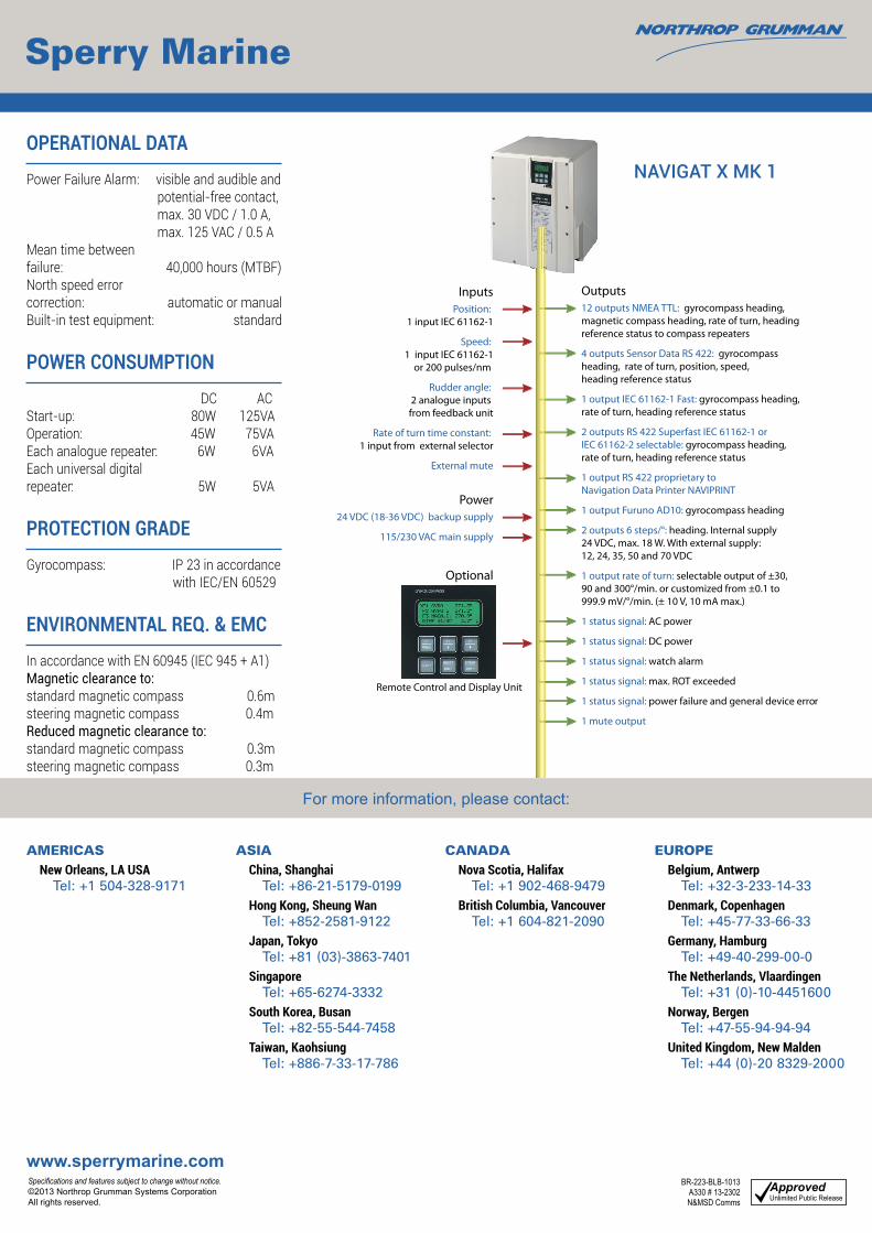
Remote Control and Display Unit
NAVIGAT X MK 1
InputsPosition:
1 input IEC 61162-1
Speed: 1 input IEC 61162-1
or 200 pulses/nm
Rudder angle: 2 analogue inputs from feedback unit
Rate of turn time constant: 1 input from external selector
External mute
Power24 VDC (18-36 VDC) backup supply
115/230 VAC main supply
Optional
Outputs12 outputs NMEA TTL: gyrocompass heading, magnetic compass heading, rate of turn, heading reference status to compass repeaters
4 outputs Sensor Data RS 422: gyrocompass heading, rate of turn, position, speed, heading reference status
1 output IEC 61162-1 Fast: gyrocompass heading, rate of turn, heading reference status
2 outputs RS 422 Superfast IEC 61162-1 or IEC 61162-2 selectable: gyrocompass heading, rate of turn, heading reference status
1 output RS 422 proprietary to Navigation Data Printer NAVIPRINT
1 output Furuno AD10: gyrocompass heading
2 outputs 6 steps/°: heading. Internal supply 24 VDC, max. 18 W. With external supply: 12, 24, 35, 50 and 70 VDC
1 output rate of turn: selectable output of ±30, 90 and 300°/min. or customized from ±0.1 to 999.9 mV/°/min. (± 10 V, 10 mA max.)
1 status signal: AC power
1 status signal: DC power
1 status signal: watch alarm
1 status signal: max. ROT exceeded
1 status signal: power failure and general device error
1 mute output