naval postgraduate · pdf filensn 7540-01-280-5500 standard form 298 (rev. 2-89) ... 3....
TRANSCRIPT

NAVAL POSTGRADUATE
SCHOOL
MONTEREY, CALIFORNIA
THESIS
Approved for public release; distribution is unlimited
INTEGRATION OF MINI-UAVS AT THE TACTICAL OPERATIONS LEVEL: IMPLICATIONS OF OPERATIONS,
IMPLEMENTATION, AND INFORMATION SHARING
by
Collier C. Crouch
June 2005 Thesis Advisor: James Ehlert Second Reader: Bill Kemple Third Reader: Edward Fisher

THIS PAGE INTENTIONALLY LEFT BLANK

i
REPORT DOCUMENTATION PAGE Form Approved OMB No. 0704-0188 Public reporting burden for this collection of information is estimated to average 1 hour per response, including the time for reviewing instruction, searching existing data sources, gathering and maintaining the data needed, and completing and reviewing the collection of information. Send comments regarding this burden estimate or any other aspect of this collection of information, including suggestions for reducing this burden, to Washington headquarters Services, Directorate for Information Operations and Reports, 1215 Jefferson Davis Highway, Suite 1204, Arlington, VA 22202-4302, and to the Office of Management and Budget, Paperwork Reduction Project (0704-0188) Washington DC 20503. 1. AGENCY USE ONLY (Leave blank)
2. REPORT DATE June 2005
3. REPORT TYPE AND DATES COVERED Master’s Thesis
4. TITLE AND SUBTITLE: Integration of Mini-UAVs at the Tactical Operations Level: Implications of Operations, Implementation, and Information Sharing 6. AUTHOR(S) Collier C. Crouch
5. FUNDING NUMBERS
7. PERFORMING ORGANIZATION NAME(S) AND ADDRESS(ES) Naval Postgraduate School Monterey, CA 93943-5000
8. PERFORMING ORGANIZATION REPORT NUMBER
9. SPONSORING /MONITORING AGENCY NAME(S) AND ADDRESS(ES)
N/A
10. SPONSORING/MONITORING AGENCY REPORT NUMBER
11. SUPPLEMENTARY NOTES The views expressed in this thesis are those of the author and do not reflect the official policy or position of the Department of Defense or the U.S. Government. 12a. DISTRIBUTION / AVAILABILITY STATEMENT Approved for public release; distribution is unlimited
12b. DISTRIBUTION CODE
13. ABSTRACT (maximum 200 words) Small units maneuvering on the battlefield have little time to establish data links and interface with
the Global Information Grid (GIG) while trying to achieve an objective. The bandwidth and interface requirements necessary to receive live data from current strategic level systems limit the small unit operational user’s ability to receive and act upon data and intelligence. Without the ability to interface with current strategic-level UAV assets, these small units are left without a comprehensive operational picture. Mini-UAVs offer the capability for the tactical user, in a variety of missions, to have direct control over the aerial asset without intervention from higher authority. Organic UAV assets can be used to collect data relevant to small units without the need for connecting to intelligence systems. This offers increased mobility and a dedicated collection platform; however, there are still drawbacks to this capability. This thesis examines mini-UAVs, and their integration into the Coalition Operating Area Surveillance and Targeting System (COASTS) network.
15. NUMBER OF PAGES
199
14. SUBJECT TERMS COASTS, Unmanned Aerial Vehicles, Mini-UAVs, Command and Control, Computers, Communications, Intelligence. Surveillance, Reconnaissance, C4ISR, COTS, Commercial-off-the-shelf technology, Local Persistence.
16. PRICE CODE
17. SECURITY CLASSIFICATION OF REPORT
Unclassified
18. SECURITY CLASSIFICATION OF THIS PAGE
Unclassified
19. SECURITY CLASSIFICATION OF ABSTRACT
Unclassified
20. LIMITATION OF ABSTRACT
UL
NSN 7540-01-280-5500 Standard Form 298 (Rev. 2-89) Prescribed by ANSI Std. 239-18

ii
THIS PAGE INTENTIONALLY LEFT BLANK
iii
Approved for public release; distribution is unlimited
INTEGRATION OF MINI-UAVS AT THE TACTICAL OPERATIONS LEVEL: IMPLICATIONS OF OPERATIONS, IMPLEMENTATION, AND INFORMATION
SHARING
Collier Craig Crouch Ensign, United States Navy
B.S. Chemistry, United States Naval Academy, 2004
Submitted in partial fulfillment of the requirements for the degree of
MASTER OF SCIENCE IN SYSTEMS TECHNOLOGY
from the
NAVAL POSTGRADUATE SCHOOL June 2005
Author: Collier Craig Crouch Approved by: James Ehlert
Thesis Advisor
Bill Kemple Second Reader Edward Fisher Third Reader Dan Boger Chairman, Department of Information Sciences

iv
THIS PAGE INTENTIONALLY LEFT BLANK

v
ABSTRACT
Small units maneuvering on the battlefield have little time to establish data
links and interface with the Global Information Grid (GIG) while trying to achieve
an objective. The bandwidth and interface requirements necessary to receive live
data from current strategic level systems limit the small unit operational user’s
ability to receive and act upon data and intelligence. Without the ability to
interface with current strategic-level UAV assets, these small units are left
without a comprehensive operational picture. Mini-UAVs offer the capability for
the tactical user, in a variety of missions, to have direct control over the aerial
asset without intervention from higher authority. Organic UAV assets can be
used to collect data relevant to small units without the need for connecting to
intelligence systems. This offers increased mobility and a dedicated collection
platform; however, there are still drawbacks to this capability. This thesis
examines mini-UAVs, and their integration into the Coalition Operating Area
Surveillance and Targeting System (COASTS) network.

vi
THIS PAGE INTENTIONALLY LEFT BLANK
vii
TABLE OF CONTENTS I. INTRODUCTION.................................................................................................. 1
A. INTRODUCTION ..................................................................................... 1 B. OVERVIEW.............................................................................................. 2 C. THE EMERGENCE OF UAV TECHNOLOGY ......................................... 4 D. THE COASTS PROGRAM ...................................................................... 6
II. UAV OVERVIEW ................................................................................................ 9 A. INTRODUCTION ..................................................................................... 9 B. UAV COMPONENTS............................................................................... 9 C. PLANNING INVOLVED IN UAV OPERATIONS ................................... 11 D. CLASSES OF UAVS ............................................................................. 12 E. MQ-1 / MQ-9 PREDATOR ..................................................................... 15 F. RQ-2 PIONEER...................................................................................... 18 G. RQ-5 HUNTER ...................................................................................... 20 H. RQ-7 SHADOW ..................................................................................... 21 I. RQ-4 GLOBAL HAWK........................................................................... 23 J. FMQ-151 POINTER................................................................................ 25 K. DRAGON EYE....................................................................................... 26 L. DESERT HAWK..................................................................................... 28 M. UAV PRODUCT DISSEMINATION....................................................... 29 N. SUMMARY ............................................................................................ 30
III. MINI-UAVS....................................................................................................... 33 A. INTRODUCTION ................................................................................... 33 B. MINI-UAV FACTORS ............................................................................ 34
1. Mini-UAV Planning/ Preflight................................................... 34 2. Time Aloft/ Loiter Time ............................................................ 35 3. Ability to Launch ...................................................................... 36 4. Wind and Atmospheric Conditions ........................................ 36 5. Density Altitude........................................................................ 38 6. Temperature ............................................................................. 38 7. Operations in Dense Areas/ Over-the-Horizon ...................... 38 8. Number of People to Operate.................................................. 40 9. Communications Security....................................................... 40 10. Frequency Separation ............................................................. 41 11. Tie-in to the Information Grid.................................................. 42 12. Landing..................................................................................... 43 13. Field Support Requirements................................................... 43
C. MINI-UAV SPECIFIC MISSIONS........................................................... 44 1. Intelligence, Surveillance, and Reconnaissance (ISR) ........... 45 2. Force Protection ........................................................................ 46 3. C2/ Communications ................................................................. 47
viii
4. Navigation .................................................................................. 47 5. Combat Search and Rescue (CSAR) ........................................ 48
D. LOCAL PERSISTENCE ........................................................................ 48 E. SUMMARY............................................................................................. 51
IV. COASTS PROGRAM OVERVIEW .................................................................. 53 A. INTRODUCTION ................................................................................... 53 B. COASTS OVERVIEW............................................................................ 53 C. CYBER DEFENSE SYSTEMS INC. UAV OVERVIEW.......................... 57
1. CDUAV Vehicle........................................................................... 57 2. Control and Data Links.............................................................. 58 3. GCS............................................................................................. 59 4. GCS software ............................................................................. 60
D. UAVS IN THE COASTS PROGRAM..................................................... 62 E. CYBER DEFENSE SYSTEMS INCUAV VIDEO INTEGRATION .......... 63 F. SUMMARY............................................................................................. 65
V. COASTS CASE STUDY................................................................................... 67 A. INTRODUCTION ................................................................................... 67 B. SCENARIO ............................................................................................ 67
1. General Information................................................................... 67 2. Network Description .................................................................. 68 3. Detailed Scenario Description .................................................. 70 4. Measures of Effectiveness/ Measures of Performance .......... 71
C. RESULTS .............................................................................................. 72 1. Measures of Effectiveness........................................................ 72
a. Sensor Event ............................................................... 72 b. Camera Viewing .......................................................... 72 c. ID Van........................................................................... 72 d. ID Traffickers ............................................................... 72 e. Continuous Surveillance ............................................ 72 f. TrackPointC2™ Chat .................................................. 73 g. TrackPointC2™ Tracking ........................................... 73 h. TrackPointC2™ Tasking............................................. 73 j. Tacticomp Video Access............................................ 73
2. Observations.............................................................................. 73 3. Limitations.................................................................................. 74 4. Follow-on Suggestions ............................................................. 75
D. UAV USE.............................................................................................. 76 1. Intended Use .............................................................................. 77 2. Observations.............................................................................. 77 3. Limitations.................................................................................. 79
E. SUMMARY............................................................................................. 79
VI. CONCLUSIONS .............................................................................................. 81 A. CONCLUSIONS .................................................................................... 81 B. RECOMMENDATIONS.......................................................................... 83

ix
C. FOLLOW-ON WORK............................................................................. 84
APPENDIX A........................................................................................................... 85
LIST OF REFERENCES........................................................................................ 173
BIBLIOGRAPHY ................................................................................................... 175
INITIAL DISTRIBUTION LIST ............................................................................... 177

x
THIS PAGE INTENTIONALLY LEFT BLANK

xi
LIST OF FIGURES
Figure 1. Altitude and Weight Classification of Current UAVs (From: Weibel)..... 13 Figure 2. MQ-1 Predator UAV (From: Globalsecurity.org)................................... 15 Figure 3. Links in the Predator System (After: Globalsecurity.org) ...................... 16 Figure 4. RQ-2 Pioneer (From: Globalsecurity.org) ............................................. 18 Figure 5. RQ-5 Hunter (From: Globalsecurity.org)............................................... 20 Figure 6. RQ-7 Shadow (From: Globalsecurity.org) ............................................ 21 Figure 7. RQ-4 Global Hawk (From: Globalsecurity.org) ..................................... 23 Figure 8. FMQ-151 Pointer mini-UAV (From: Aerovironment.com) ..................... 25 Figure 9. Dragon Eye mini-UAV (From: Globalsecurity.org)................................ 26 Figure 10. Desert Hawk mini-UAV (From: Globalsecurity.org) .............................. 28 Figure 11. UAV Line-of-sight Control Link Limitations ........................................... 39 Figure 12. Local Persistence of Information ......................................................... 49 Figure 13. Effects of Combining Intelligence from mini-UAVs and High Altitude
UAVs .................................................................................................. 51 Figure 14. COASTS Architecture (From: Appendix).............................................. 54 Figure 15. TrakPointC2™ User Interface .............................................................. 56 Figure 16. Cyber Defense Systems Inc. CyberBUG™ .......................................... 58 Figure 17. CyberBUG™ Control Station (From: Cyber Defense Systems Inc.)..... 59 Figure 18. UAV Ground-control Station Software.................................................. 60 Figure 19. Dazzle Video-capture Device ............................................................... 63 Figure 20. Microsoft NetMeeting ........................................................................... 64 Figure 21. COASTS Scenario ............................................................................... 69

xii
THIS PAGE INTENTIONALLY LEFT BLANK
xiii
LIST OF TABLES
Table 1. MQ-1/MQ-9 Predator Data (From: UAV Reliability Study) ..................... 15 Table 2. RQ-2B Pioneer Data (From: UAV Reliability Study) .............................. 18 Table 3. RQ-5 Hunter Data (From: UAV Reliability Study) .................................. 20 Table 4. RQ-7 Shadow Data (From: UAV Reliability Study) ................................ 22 Table 5. RQ-4A Global Hawk Data (From: UAV Reliability Study) ...................... 23 Table 6. FMQ-151 Pointer mini-UAV Data (From: Jane's Unmanned Aerial
Vehicles and Targets 182).................................................................. 25 Table 7. Dragon Eye Data (From: UAV Reliability Study).................................... 27 Table 8. Desert Hawk Data (From: Jane's Unmanned Aerial Vehicles and
Targets 244) ....................................................................................... 28

xiv
THIS PAGE INTENTIONALLY LEFT BLANK
xv
LIST OF KEY WORDS, SYMBOLS, ACRONYMS AND ABBREVIATIONS
2D Two Dimensional
ATO Air Tasking Order
BDA Battle Damage Assessment
C4I Command and Control, Computers, Communications and
Intelligence
CN Counter Narcotics
CNO Chief of Naval Operations
COASTS Coalition Operating Area Surveillance and Targeting System
COTS Commercial-off-the-shelf
CSAR Combat Search and Rescue
DARPA Defense Advanced Research Projects Agency
DCGS Distributed Common Ground System
DOD Department of Defense
DRDO Thai Department of Research & Development Office
DTAC Digital Training Access Center
EO Electro-optical
FLIR Forward Looking Infrared
FP Force Protection
GCS Ground-control Station
GHz Gigahertz
GIG Global Information Grid
GPS Global Positioning System
xvi
IOC Initial Operational Capability
IR Infrared
ISR Intelligence, Surveillance, and Reconnaissance
ISRT Intelligence, Surveillance, Reconnaissance, and Target
Acquisition
JPO-UAV Joint Project Office for Unmanned Aerial Vehicles
JUSMAGTHAI Joint U.S. Military Advisor's Group Thailand
LCE Launch and Recovery Element
Li Lithium
LOS Line-of-sight
MCE Mission Control Element
MCM Mine Counter Measures
MCP Mobile Command Post
METOC Meteorology and Oceanography
MHz Megahertz
Mini-UAVs Miniature Unmanned Aerial Vehicles
MOE Measures of Effectiveness
MOP Measures of Performance
MSE Mobile Subscriber Equipment
NiCd Nickel Cadmium
NIMA National Imagery and Mapping Agency
NPS Naval Postgraduate School
OFDM Orthogonal Frequency Division Multiplexing
OSD Office of the Secretary of Defense

xvii
OTH Over-the-Horizon
RATO Rocket Assisted Take-off
RF Radio Frequency
RTSC Thailand Royal Thai Supreme Command
RTARF Royal Thai Armed Forces
SA Situational Awareness
SATCOM Satellite Communications
SEAD Suppression of Enemy Air Defenses
SIGINT Signals Intelligence
TALD Tactical Air Launched Decoys
TAMD Theater Air and Missile Defense
TCS Tactical Control System
TEMP Test and Evaluation Master Plan
TRL Technology Readiness Level
UAV Unmanned Aerial Vehicle
USB Universal Serial Bus
VLC VideoLAN Client
WLAN Wireless Local Area Network
WMD Weapons of Mass Destruction
WOT War on Terror

xviii
THIS PAGE INTENTIONALLY LEFT BLANK
xix
ACKNOWLEDGMENTS
I would like to thank the following people: James Ehlert, Bill
Kemple, Ed Fisher, Mike Clement, Ron Russell, Dwayne Lancaster, Chris Lee,
and Rob Hochstedler. I would like to especially thank Alexis Wise and Kevin
Barrett for their constant support and guidance.
I would also like to thank my parents for their enduring support.

xx
THIS PAGE INTENTIONALLY LEFT BLANK

1
I. INTRODUCTION
A. INTRODUCTION Since descending from the trees of the jungle to roam the plains,
humankind has had to endure limited resources. In an effort to secure these
resources for their survival, humans formed societies and initiated civilization and
ownership. Yet as humans became more nomadic, they encountered other
wandering tribes who were also eager to secure the limited resources for their
own survival. As competition for these scarce resources increased, the dawn of
warfare emerged.
Society developed tactics and techniques to outsmart the enemy and gain
control of the resources necessary for survival. Technology has forced tactics to
change; however, the need for information has increased. Information is pivotal
to the success of any military campaign. With knowledge of the enemy, a
commander can decide whether to attack or retreat. Information can enable a
small force to overcome the advantages that a large adversary may possess.
Liddell Hart’s “indirect approach” relies on the attacking commander’s ability to
obtain superior knowledge of the enemy’s forces in order to exploit the
advantage.
Classical information gathering has both strategic and tactical implications.
Strategy is the overarching concept that a commander employs in order to force
a decision (with or without battle). If battle must be made, it is through tactical
decisions that a battle may be won. The object of obtaining information (whether
it be enemy unit locations, enemy force strength, enemy capabilities, or enemy
intentions) has been to enable strategic decisions to be made for tactical
implementation. Throughout military history this has long been a corollary of
successful warfare. Today the wealth of information and the capabilities of
existing systems are melding the lines between tactical and strategic decision-
making. The speed of disseminating information is producing a battleground
where tactical decisions can have immediate strategic implications. World

2
opinion now plays a major role in military operations. “The CNN effect” can
instantly inform both the world and the enemy of current operations and
intentions, as well as influence the views of people all over the world. The result
is that media outlets, enemy Command and Control, Computers,
Communications and Intelligence (C4I) systems, and even individuals can affect
public opinion in real-time, thus turning a tactical victory into a strategic loss.
One mechanism to address this phenomenon is to provide more
information to the tactical commanders, enabling them to consider the
consequences of their actions more effectively. Unmanned Aerial Vehicles
(UAVs) uniquely broaden the operational picture of tactical commanders.
B. OVERVIEW
Unmanned Aerial Vehicles are defined in Department of Defense (DOD)
Joint Publication 1-02 as:
A powered, aerial vehicle that does not carry a human operator, uses aerodynamic forces to provide vehicle lift, can fly autonomously or be piloted remotely, can be expendable or recoverable, and can carry a lethal or non-lethal payload. Ballistic or semi ballistic vehicles, cruise missiles, and artillery projectiles are not considered unmanned aerial vehicles.
It is important to consider the differences between UAV systems and other
unmanned weapons. "The key discriminates are (1) UAVs are equipped and
employed for recovery at the end of their flight, and cruise missiles are not, and
(2) munitions carried by UAVs are not tailored and integrated into their airframe
whereas the cruise missile's warhead is" (Unmanned Aerial Vehicle Roadmap 2).
Unmanned Aerial Vehicles (UAVs) are increasing the wealth of
information available to commanders at the strategic, operational, and tactical
level, yet they cannot provide perfect information. Current UAV systems are
deployed at the strategic and operational levels and provide very little real-time
intelligence and feedback for tactical users. Moreover, the current systems are
bulky and require a great deal of support structure. These systems are plagued
by problems with reliability and integration. Larger units (battalion strength and

3
larger) have little problem integrating UAV units into operations, but the control of
these units is usually dedicated to fulfilling battalion level and higher tasking.
Tactical users at the squad and platoon level, as well as special operations units,
have little ability to obtain information from these strategic-level assets. The
information from these strategic-level units is usually routed to a processing
center and then sent to tactical units with a large delay. Tactical users are
denied real-time and near-real-time data that are immediately applicable to
operations as they engage the enemy.
Mini-UAVs can improve this situation by equipping the tactical commander
with a man-portable system to obtain real-time intelligence that can be
immediately exploited. These systems serve as locally controlled assets,
providing crucial information to small unit commanders and further inhibiting
interference at the tactical level.
These mini-UAVs generally have wingspans between six inches and ten
feet and can fly between 20 to 50 miles per hour (Coffey 1), yet these mini-UAVs,
of relatively simple design, yield a great deal of versatility and portability.
Additionally, various control stations have been devised to interface with these
vehicles. Therefore, once the data from the tactical units are integrated, the
widespread distribution of mini-UAVs can furnish strategic-level commanders
with more accurate details of individual unit operations.
The Chief of Naval Operations has recently underscored a need for a
move from “reconnaissance to persistence,” implying that the Navy must have
perfect information for all situations (CNO Guidance for 2005 18). Of course, the
development of persistent information collection systems will take time and
resources. The limits of the current systems and the inability of tactical users to
interface with these systems constrain the flow of information to the tactical level.
In its After Action Report from Operation IRAQI FREEDOM the Third
Infantry Division (Mechanized) stated that, "As a result of the division's fast-
paced operations during the first several days of the war, the mobile subscriber
equipment (MSE) network was not often established for the DTAC [Digital

4
Training Access Center] and the maneuver brigades." This and other networks
are important in establishing communications with other units on the battlefield.
The fast paced movement of troops inhibits and limits the ability of units to
connect into intelligence dissemination systems.
Mini-UAVs can solve this problem by allowing tactical units to determine
and fulfill their need for Intelligence, Surveillance, Reconnaissance, and Target
Acquisition (ISRT) data without connecting to intelligence dissemination systems.
However, the development of mini-UAVs through the traditional acquisition
process will be costly and time consuming. This capability will require a great
number of iterations and a vast number of new systems to be produced, resulting
in a great delay, while the need for information will still grow. Commercial-off-
the-shelf (COTS) technology can currently furnish a number of capabilities
economically and rapidly.
One milestone on the path to persistence should be the development of a
concept of “local persistence.” This capability will offer tactical users information
directly applicable through organic ISRT units. Organic ISRT units reduce the
need for information to flow to the tactical units by allowing them to collect their
own information. Higher-level commanders can later access the information
collected by these units.
By collecting ISRT data through organic units, tactical users can
immediately assess potential actions that may neutralize the targets under their
purview. An organic UAV capability can be fielded quite quickly due to the vast
array of mini-UAV systems now available from the commercial world. COTS
technology currently offers an affordable, mass-produced method for providing
local persistence to the military.
C. THE EMERGENCE OF UAV TECHNOLOGY
Prior to FY1987, UAVs in the US inventory were built as experimental
units, not intended for mass production and operational employment. FY1987
marked the first year that acquisition programs for UAVs were started, and

5
Operation DESERT STORM marked the first major operational use of UAVs by
the U.S.
UAVs in Operation DESERT STORM were used for intelligence,
surveillance, and reconnaissance missions. They were also utilized as Tactical
Air Launched Decoys (TALD) as well as for Battle Damage Assessment (BDA)
and targeting. The RQ-21 Pioneer was so successful at targeting and providing
BDA in Operations DESERT SHIELD and DESERT STORM that Iraqi troops
even surrendered to it as it flew overhead.
The most famous incident occurred when USS Missouri (BB 63), using her Pioneer to spot 16 inch gunfire, devastated the defenses of Faylaka Island off the coast near Kuwait City. Shortly thereafter, while still over the horizon and invisible to the defenders, the USS Wisconsin (BB 64) sent her Pioneer over the island at low altitude. When the UAV came over the island, the defenders heard the obnoxious sound of the two-cycle engine since the air vehicle was intentionally flown low to let the Iraqis know that they were being targeted. Recognizing that with the "vulture" overhead, there would soon be more of those 2,000-pound naval gunfire rounds landing on their positions with the same accuracy, the Iraqis made the right choice and, using handkerchiefs, undershirts, and bedsheets, they signaled their desire to surrender. ("RQ-2A Pioneer Unmanned Aerial Vehicle (UAV)")
Today, UAVs are quickly assuming the role previously performed by
manned intelligence gathering aircraft. UAVs are particularly good at replacing
manned aircraft in areas that are considered too “dull, dirty, or dangerous." The
products of UAV sensor data are becoming vital to the continued success of the
United States Military. "The current architecture stresses the available bandwidth
and results in less than desired distribution of data" (Defense Science Board, ix).
The bandwidth required to distribute this data to tactical users is not available.
Mechanisms to deliver large amounts of data to tactical users must be developed
to increase the effectiveness of these units and allow them to interoperate with
future systems.
In the National Defense Authorization Act for FY2001 Congress stated,
“Within ten years, one-third of U.S. military operational deep strike aircraft will be
6
unmanned” (Senate Committee on Armed Services 141). UAVs are already
becoming the platform of choice for intelligence gathering operations. Projected
increases in technology will spur development of more capable systems to
replace manned aircraft. Clearly, the future of UAVs will extend into the realm of
unmanned armed combat.
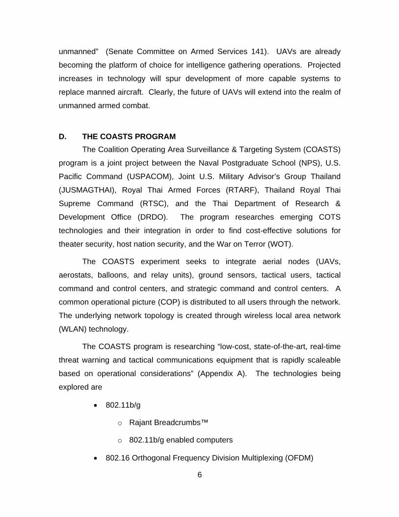
D. THE COASTS PROGRAM The Coalition Operating Area Surveillance & Targeting System (COASTS)
program is a joint project between the Naval Postgraduate School (NPS), U.S.
Pacific Command (USPACOM), Joint U.S. Military Advisor’s Group Thailand
(JUSMAGTHAI), Royal Thai Armed Forces (RTARF), Thailand Royal Thai
Supreme Command (RTSC), and the Thai Department of Research &
Development Office (DRDO). The program researches emerging COTS
technologies and their integration in order to find cost-effective solutions for
theater security, host nation security, and the War on Terror (WOT).
The COASTS experiment seeks to integrate aerial nodes (UAVs,
aerostats, balloons, and relay units), ground sensors, tactical users, tactical
command and control centers, and strategic command and control centers. A
common operational picture (COP) is distributed to all users through the network.
The underlying network topology is created through wireless local area network
(WLAN) technology.
The COASTS program is researching “low-cost, state-of-the-art, real-time
threat warning and tactical communications equipment that is rapidly scaleable
based on operational considerations” (Appendix A). The technologies being
explored are
• 802.11b/g
o Rajant Breadcrumbs™
o 802.11b/g enabled computers
• 802.16 Orthogonal Frequency Division Multiplexing (OFDM)

7
o Redline Communications AN-50e
• Satellite Communications (SATCOM)
• Wearable Computing Devices
o Inter-4 Tacticomp PDAs
• Unattended Air and Ground Sensors
o Crossbow Sensor Grid
• Mobile Command and Control Platforms
• Persistent Surveillance
• Shared Situational Awareness
o TrakPointC2™
• Hastily Formed Networks
• Ultra Wideband Technologies
• GPS Tracking Technologies
o TrakPointC2™
• GPS Denied Tracking Devises
o TrakPointC2™
• Unmanned Aerial Vehicles (Micro, Mini, and others).
o Cyber Defense Systems Inc. CyberBUG™
This thesis focuses on the operational considerations of mini-UAVs at the
tactical level as demonstrated by the integration of mini-UAVs into the COASTS
network.

8
THIS PAGE INTENTIONALLY LEFT BLANK
9
II. UAV OVERVIEW
A. INTRODUCTION UAVs are organized into categories based upon their size and endurance.
Traditionally, UAVs have been complex systems requiring a large footprint and a
wide array of support staff to operate. All of the equipment, shelters,
communications gear, personnel, and personnel support structures encompass
the footprint that must be transported to the area of operations. The logistical
requirements to transport and erect all of this gear grow exponentially as the size
of the footprint grows. The size of these support structures has limited the ability
for small units of maneuver (companies, platoons, squads) to obtain an organic
UAV capability and remain mobile.
Small units rarely gain access to data from UAVs to support their
operations. Access to data from strategic-level UAV systems requires heavily
planned operations with a vast array of support structures to integrate battalion
and larger systems into small-unit operations. To combat this problem, smaller
systems with decreased size and endurance are currently being considered to
support smaller forces.
B. UAV COMPONENTS A UAV system is generally composed of a vehicle, a ground-control
station, a tracking control station, and a data dissemination system. Some UAV
systems can downlink data to remote terminals in order to exploit the data from
the UAV immediately. Control systems have been designed to operate each
specific type of UAV and are not generally interchangeable. The diversity of
missions and equipment in different types of UAVs has led to the development of
specific control systems to support individual systems.
Tactical users require mobile platforms capable of rapid deployment and
possible control while moving. Strategic users require robust data links and large

10
control stations to support the wide varieties of payloads usually found on these
systems. Stovepipe development has limited the interoperability of UAV ground-
control stations; however, the Tactical Control System (TCS) currently under
development by the Joint Project Office for UAVs (JPO-UAV) will allow multiple
types of UAVs to be controlled through a single control station ("UAV Tactical
Control System").
The vehicle includes a number of subsystems, such as a propulsion
source, a payload, avionics equipment, a power supply, and data link equipment.
Larger UAVs use fuel-powered engines in order to attain flight. Smaller UAVs
typically use either gasoline-powered engines or electrically powered engines.
The payload is composed of Electro-optical (EO) cameras, Infrared (IR) cameras,
signals collection packages, or a vast array of other packages that can be
interchanged to support specific missions. The avionics equipment controls the
direction of flight, the altitude and attitude of the aircraft, and its speed. The
power supply powers the avionics system as well as the data link and the
payload. The power may be supplied by a battery, or produced by an engine.
The data link is arguably the most important part of the system. The data
link allows control from the control station as well as down linking of the collected
data. Most data processing and storage must be performed on the ground to
conserve space and weight on the UAV. Smaller systems have limited space for
onboard processing. Additionally, smaller UAVs are used for providing real-time
and near-real-time data that does not require storage and processing onboard
the aircraft.
UAVs usually contain two data links, a control data link and a data link to
transmit the payload data. The control data link and the payload data link are not
always separate links. The control data link handles the vehicle telemetry data
and the control signals from the ground control station in order to provide vehicle
control. The payload data link generates video, IR, or other data from the UAV to
the user for processing and dissemination. In some current systems, such as the

11
RQ-2 Pioneer, mobile users can interface with the payload of the UAV to receive
data from overhead.
C. PLANNING INVOLVED IN UAV OPERATIONS UAVs are considered to be either organic assets or non-organic assets.
Organic assets are those that are under the direction of the commander of a
specific unit, whether it be squad, brigade, battalion, or corps. The UAV is
considered to be a part of that unit, and the commander has control over its
tasking. Non-organic assets are assets that a commander does not control.
Consider the case in which a battalion owns a UAV. The UAV is organic to the
battalion, but it would be non-organic to a squad in that battalion. The squad
leader would have no way to task the battalion level unit without using a non-
organic procedure. The squad would be able to obtain data from this UAV, but it
would not control the UAV directly, and it would not receive the data immediately.
UAVs can perform pre-planned missions, immediate missions, or can be
dynamically retasked to support urgent data collection requirements. All UAV
assets are susceptible to being diverted by a higher authority (Marine Corps
Warfighting Publication 3-42.1: Unmanned Aerial Vehicle Operations 4-3).In a
Marine Corps UAV squadron the commander controls organic UAV tasking.
Organic mission planning procedures are similar to non-organic procedures,
except they provide more control over the collection of data.
UAV planning and tasking requires a great deal of coordination in order to
ensure safe vehicle operation and collection of relevant mission data. Planned
missions involving organic assets are initiated through a Joint Tactical Air Strike
(JTAR) request. The UAV is then assigned tasking and authorization through the
Air Tasking Order (ATO) (4-4). This process is not immediate. The development
of an ATO requires 72 hours for route planning, collection planning, and airspace
coordination with other assets. Immediate organic missions “are supported via
the fastest means” possible to meet the collection requirements (4-3). Immediate
requests are met according to the availability of assets, the ATO, and other
12
priorities. Dynamic retasking of organic assets, changing the route, altitude, or
collection targets of a platform already aloft is also achieved through the fastest
means possible. These changes must be coordinated with current air assets by
either the Direct Air Support Center (DASC) or the Tactical Air Control Center
(TACC) (4-4).
Tasking of non-organic assets is also accomplished via the JTAR, but the
Joint Force Commander (JFC) J-2 determines prioritization. The lack of assets
means that some requests will not be met in a timely fashion and will lack UAV
support. Planned missions for non-organic units are received through the ATO.
Immediate tasking is developed by the execution cell of the combat operations
center and delivered to the UAV squadron for implementation.
D. CLASSES OF UAVS
UAVs are currently classified into Micro, Mini, Tactical, Medium Altitude,
and High Altitude systems. Micro-air vehicles generally operate at low altitudes,
weigh less than one pound, and have limited capabilities as individual units. They
are currently in the experimental phase and have not been implemented under
operational conditions. The small size of micro-UAVs, less than six inches, limits
their ability to transit from the immediate area of launch. These UAVs have
limited space for fuel and batteries to power their systems.
Mini-UAVs typically fly between 18 and 45 knots and weigh between 1 and
40 pounds. They have wingspans between 6 inches and 10 feet with maximum
ranges being limited by the horizon. Mini-UAVs must maintain line-of-sight (LOS)
between the aircraft and the ground station. The small size of these units inhibits
the ability to carry satellite communications gear onboard for Over-the-Horizon
(OTH) communications. Mini-UAVs are easily supportable with a small footprint
and require very little logistical support. These systems are designed to provide
an organic UAV capability to small forces such as Special Operations, company,
platoon, and squad units.
13
Tactical UAVs are larger systems that require a great deal of support,
maintenance and manpower. On the other hand, they provide farther range and
longer loiter capabilities than smaller, less capable systems. These systems are
typically between 60 to 1000-pounds and operate at low to medium altitudes.
They are typically launched utilizing a runway, a catapult, or a rocket assisted
launch system.
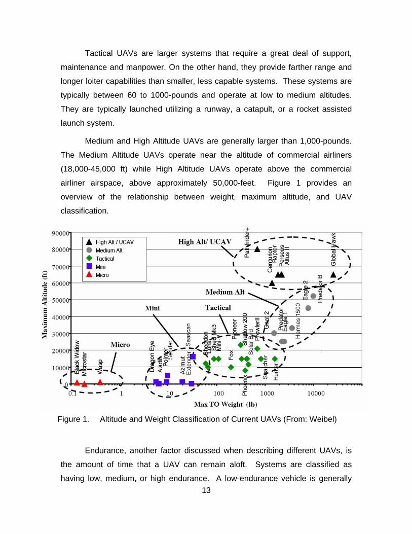
Medium and High Altitude UAVs are generally larger than 1,000-pounds.
The Medium Altitude UAVs operate near the altitude of commercial airliners
(18,000-45,000 ft) while High Altitude UAVs operate above the commercial
airliner airspace, above approximately 50,000-feet. Figure 1 provides an
overview of the relationship between weight, maximum altitude, and UAV
classification.
Figure 1. Altitude and Weight Classification of Current UAVs (From: Weibel)
Endurance, another factor discussed when describing different UAVs, is
the amount of time that a UAV can remain aloft. Systems are classified as
having low, medium, or high endurance. A low-endurance vehicle is generally

14
considered to have a flight time less than six hours. These vehicles will usually
be micro-and mini-UAVs, with some tactical UAVs included in this category. A
medium endurance vehicle has a flight time between 6 and 24 hours. Tactical
UAVs usually have medium endurance. A system with more than 24 hours of
mission time is considered a high-endurance vehicle. Medium altitude and high
altitude UAVs are commonly classified in this range.
Smaller UAVs typically have low endurance due to size and weight
restrictions. These UAVs generate less lift due to smaller wingspans and less
power output from motors. Trade-offs between avionics and payloads with fuel
and energy cells can extend the range and endurance of these systems. Smaller
cameras with fewer lines of resolution and less weight and bulk can be used in
order to employ larger, heavier, more capable batteries or motors, which also
extend the range of these UAVs. Larger motors provide greater speed and
higher altitudes, but they require more space and power. Developments in
technology will produce smaller, more capable subsystems that will further
extend the range and endurance of these small systems.
Micro-UAVs are a class of UAVs currently being researched by the
Defense Advanced Research Projects Agency (DARPA) in conjunction with a
number of defense contractors. These UAVs have a short range; however, they
are being researched for their ability to participate in swarming. Swarming would
allow the individual units to act as one unit over a particular area. These small
vehicles could be carried as a payload of a larger UAV and dropped in order to
land and to loiter in a specific area. These small units would conduct a “perch
and stare” mission in which they would place themselves in a location without the
knowledge of the enemy in order to collect imagery, signals, or other types of
intelligence. This intelligence could then be stored and later collected and sent
back to headquarters through a second UAV. Naturally, the small size of these
systems would limit the power of their transmitter and antenna gain, which in turn
would limit the distance that they could transmit data.

15
E. MQ-1 / MQ-9 PREDATOR
Figure 2. MQ-1 Predator UAV (From: Globalsecurity.org)
MQ-1 MQ-9
Gross Weight 2250 lb 10,000 lb Length 28.7 ft 36.2 ft
Wingspan 48.7 ft 64 ft Ceiling 25,000 ft 45,000 ft Radius 400 NM 400 NM
Endurance 24 hrs 24 hrs
Payload 450 lbs 750 lb (internal) 3000 (external)
Cruise Speed 70 kts 220 kts Aircraft Cost (w/out
Sensors) $2.4 M $6 M Sensors EO/IR/SAR EO/IR/SAR
System Cost (4 UAVs) $26.5 M $47 M Table 1. MQ-1/MQ-9 Predator Data (From: UAV Reliability Study)
The MQ-1 Predator (Figure 2) is a General Atomics Aeronautical Systems,
Inc. aircraft classified as a medium altitude and high-endurance UAV. It is
primarily used for armed reconnaissance, airborne surveillance and target
16
acquisition. Each Predator unit is optimally composed of four aircraft including
the sensors and data links, one Ground-Control Station (GCS) and a Trojan Spirit
II Satellite Communications (SATCOM) system used for data dissemination. The
aircraft is controlled over a C-Band line-of-sight data link or a beyond line-of-sight
KU-Band satellite. The aircraft is equipped with a nose camera for use by the
operator during take-off and landing, an Electro-optic (EO) camera for daylight
and well-lit night viewing, a variable aperture infrared (IR) camera, and synthetic
aperture radar.
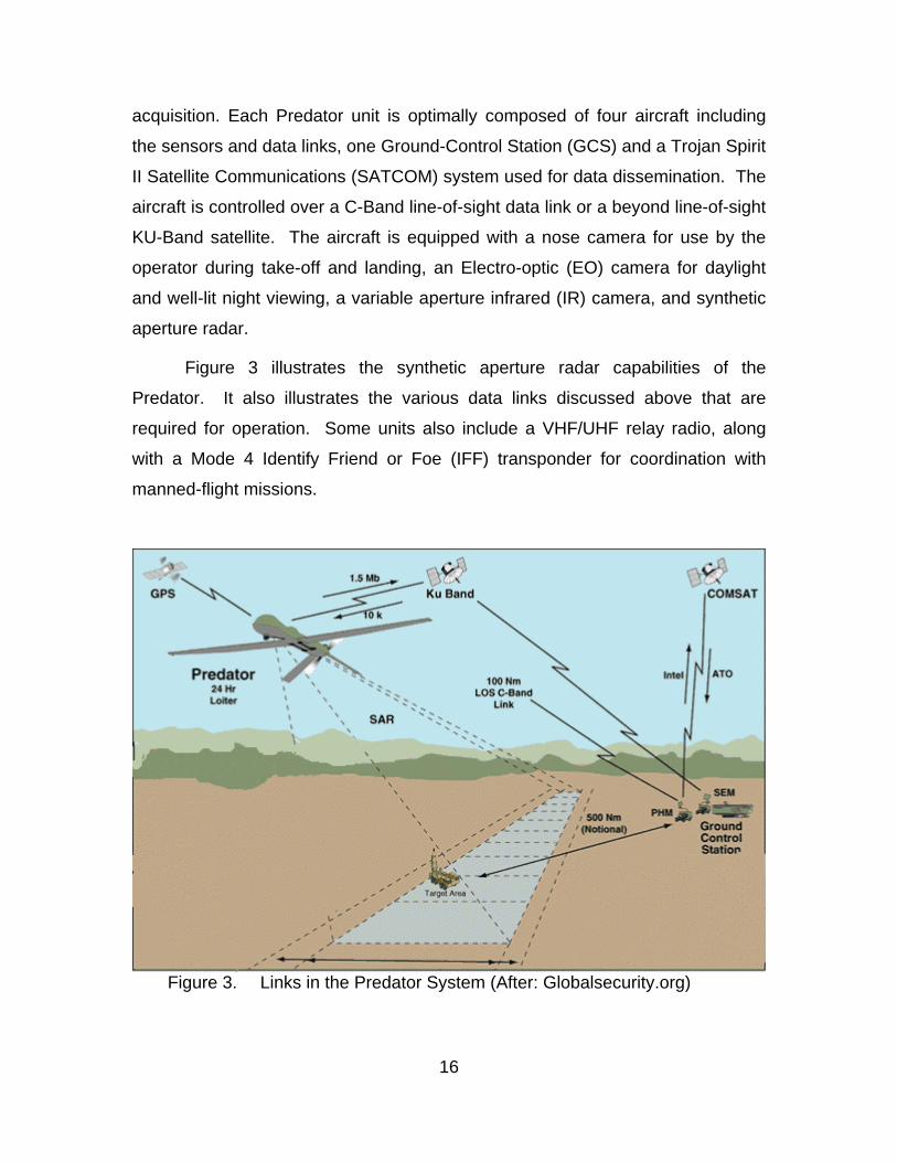
Figure 3 illustrates the synthetic aperture radar capabilities of the
Predator. It also illustrates the various data links discussed above that are
required for operation. Some units also include a VHF/UHF relay radio, along
with a Mode 4 Identify Friend or Foe (IFF) transponder for coordination with
manned-flight missions.
Figure 3. Links in the Predator System (After: Globalsecurity.org)

17
The MQ-1A and MQ-1B variants are based upon the original configuration
of the predator system. However, the MQ-1B variant is capable of firing a Hellfire
missile and carries laser-targeting equipment. The MQ-9 variant is a larger and
more reliable system featuring increased redundancy of flight-control systems in
addition to longer range, greater payload capacity, and extended loiter time. The
Predator has been nearly continuously deployed since its initial advanced
concept technology demonstration (ACTD). In order to support operations in
Bosnia, Kosovo, Albania, Afghanistan, and Iraq, units designated specifically for
testing and concept development were deployed to support operational needs
(UAV Reliability Study 8).
The Predator is launched from an improved surface or a runway.
According to the UAV Reliability Study the MQ-1 variant is 28.7-feet in length
with a wingspan of 48.7-feet. It has a radius of 400 NM and a ceiling of 25,000
feet. The aircraft cost without sensors is $2.4 million. A total system with four
aircraft and related control equipment is $26.5 million. The MQ-1 can cruise at
70-knots for over 24-hours with a 450-pounds payload. The MQ-9 variant is
36.2-feet in length with a wingspan of 64 feet. It has a radius of 400 NM with a
ceiling of 45,000 feet. The aircraft cost is $6 million without sensors. A complete
system of four aircraft costs $ 47 million. The MQ-9 is advertised to cruise at 220
knots for over 24-hours with a total payload of 3,750-pounds. (750-pounds
internal, 3000-pounds external). The Air Force has lost 26 Predators since 2002
when Operation ENDURING FREEDOM began. The Air Force has lost a total of
46 aircraft out of a total of 114 Predators during the life of the program (Bigelow).

18
F. RQ-2 PIONEER
Figure 4. RQ-2 Pioneer (From: Globalsecurity.org)
RQ-2B Gross Weight 452 lb
Length 14 ft Wingspan 17 ft
Ceiling 15,000 ft Radius 100 NM
Endurance 5 hrs Payload 75 lbs
Cruise Speed 80 kts Aircraft Cost (w/out
Sensors) $650,000 Sensors CCD/FLIR
System Cost (4 UAVs) $7 M Table 2. RQ-2B Pioneer Data (From: UAV Reliability Study) The RQ-2 Pioneer (Figure 4) is a tactical, low-endurance UAV produced
by Israeli Aircraft Industries. The United States Navy purchased it in 1985 to
provide a reconnaissance and surveillance platform for amphibious forces. The
other Service Components quickly obtained versions for use in the field. It was
originally operated off Iowa class battleships but has since been operated by
both the Army and the Marine Corps to provide tactical surveillance. The Pioneer
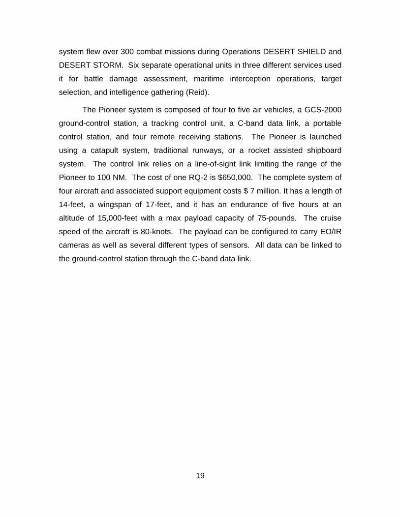
19
system flew over 300 combat missions during Operations DESERT SHIELD and
DESERT STORM. Six separate operational units in three different services used
it for battle damage assessment, maritime interception operations, target
selection, and intelligence gathering (Reid).
The Pioneer system is composed of four to five air vehicles, a GCS-2000
ground-control station, a tracking control unit, a C-band data link, a portable
control station, and four remote receiving stations. The Pioneer is launched
using a catapult system, traditional runways, or a rocket assisted shipboard
system. The control link relies on a line-of-sight link limiting the range of the
Pioneer to 100 NM. The cost of one RQ-2 is $650,000. The complete system of
four aircraft and associated support equipment costs $ 7 million. It has a length of
14-feet, a wingspan of 17-feet, and it has an endurance of five hours at an
altitude of 15,000-feet with a max payload capacity of 75-pounds. The cruise
speed of the aircraft is 80-knots. The payload can be configured to carry EO/IR
cameras as well as several different types of sensors. All data can be linked to
the ground-control station through the C-band data link.
20
G. RQ-5 HUNTER
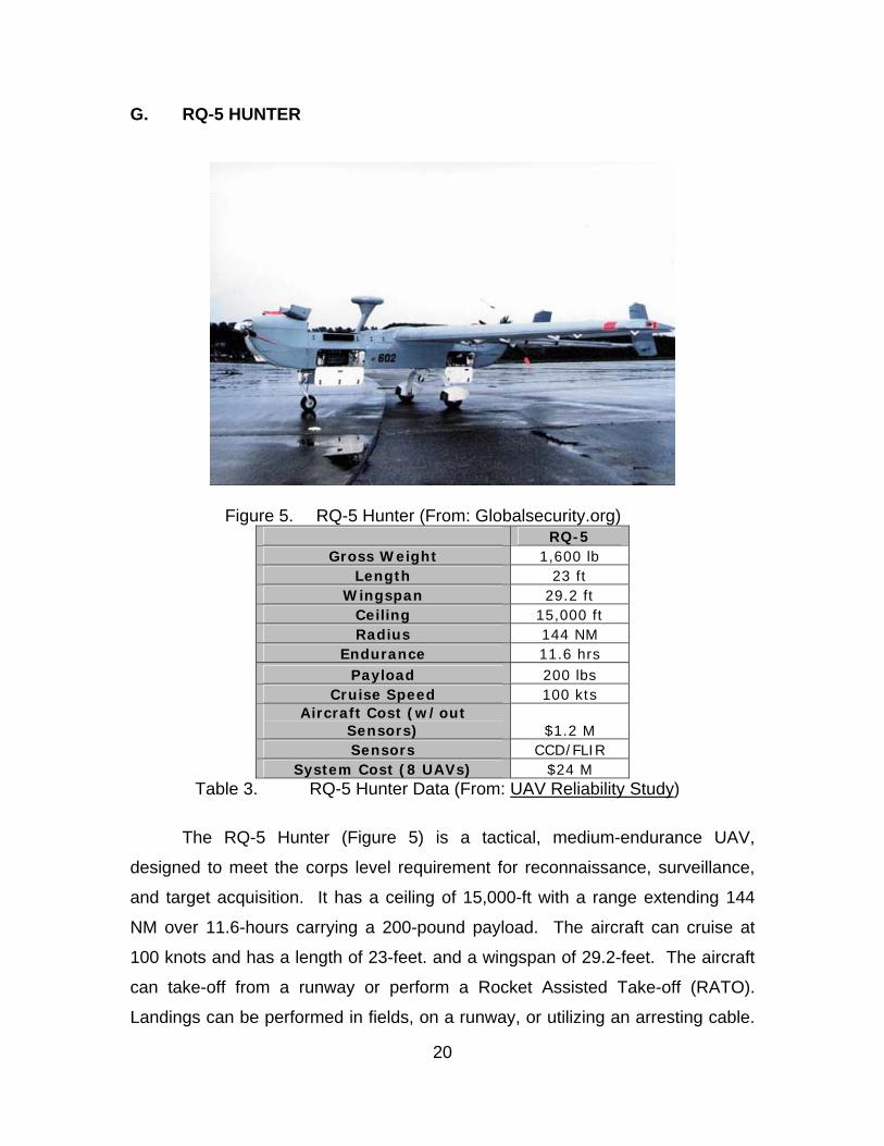
Figure 5. RQ-5 Hunter (From: Globalsecurity.org) RQ-5
Gross Weight 1,600 lb Length 23 ft
Wingspan 29.2 ft Ceiling 15,000 ft Radius 144 NM
Endurance 11.6 hrs Payload 200 lbs
Cruise Speed 100 kts Aircraft Cost (w/out
Sensors) $1.2 M Sensors CCD/FLIR
System Cost (8 UAVs) $24 M Table 3. RQ-5 Hunter Data (From: UAV Reliability Study)
The RQ-5 Hunter (Figure 5) is a tactical, medium-endurance UAV,
designed to meet the corps level requirement for reconnaissance, surveillance,
and target acquisition. It has a ceiling of 15,000-ft with a range extending 144
NM over 11.6-hours carrying a 200-pound payload. The aircraft can cruise at
100 knots and has a length of 23-feet. and a wingspan of 29.2-feet. The aircraft
can take-off from a runway or perform a Rocket Assisted Take-off (RATO).
Landings can be performed in fields, on a runway, or utilizing an arresting cable.
21
("Hunter RQ-5A Tactical Unmanned Aerial Vehicle, USA/Israel"). Its basic link is
a line-of-sight C-band data link. A second aircraft can act as a data and control
link to extend the range of the system. The system has a large logistical footprint
consisting of eight aircraft, two ground-control shelters, one mission planning
shelter, one launch and recovery shelter, two ground-data terminals, eight
modular mission payloads, and four air-data relays. Each system costs $ 24
million with each aircraft costing $ 1.2 million. The Hunter system, though
plagued by multiple developmental problems, has proven to be a valuable asset
to the United States Army in Iraq. It has flown over 3,100-hours since being
deployed to Iraq in January of 2003 ("Northrop Grumman Hunter UAV Achieves
3,000 Combat Hours in Iraq").
H. RQ-7 SHADOW
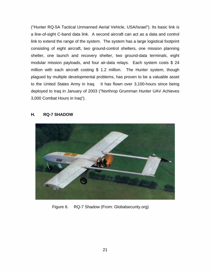
Figure 6. RQ-7 Shadow (From: Globalsecurity.org)
22
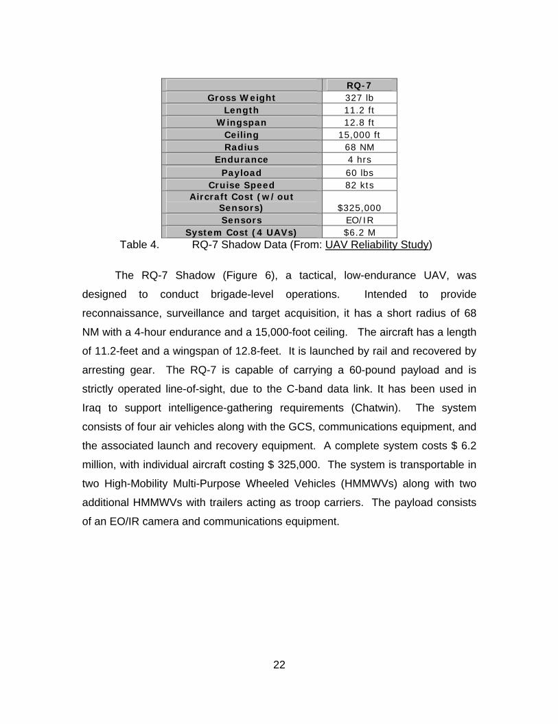
RQ-7
Gross Weight 327 lb Length 11.2 ft
Wingspan 12.8 ft Ceiling 15,000 ft Radius 68 NM
Endurance 4 hrs Payload 60 lbs
Cruise Speed 82 kts Aircraft Cost (w/out
Sensors) $325,000 Sensors EO/IR
System Cost (4 UAVs) $6.2 M Table 4. RQ-7 Shadow Data (From: UAV Reliability Study)
The RQ-7 Shadow (Figure 6), a tactical, low-endurance UAV, was
designed to conduct brigade-level operations. Intended to provide
reconnaissance, surveillance and target acquisition, it has a short radius of 68
NM with a 4-hour endurance and a 15,000-foot ceiling. The aircraft has a length
of 11.2-feet and a wingspan of 12.8-feet. It is launched by rail and recovered by
arresting gear. The RQ-7 is capable of carrying a 60-pound payload and is
strictly operated line-of-sight, due to the C-band data link. It has been used in
Iraq to support intelligence-gathering requirements (Chatwin). The system
consists of four air vehicles along with the GCS, communications equipment, and
the associated launch and recovery equipment. A complete system costs $ 6.2
million, with individual aircraft costing $ 325,000. The system is transportable in
two High-Mobility Multi-Purpose Wheeled Vehicles (HMMWVs) along with two
additional HMMWVs with trailers acting as troop carriers. The payload consists
of an EO/IR camera and communications equipment.
23
I. RQ-4 GLOBAL HAWK
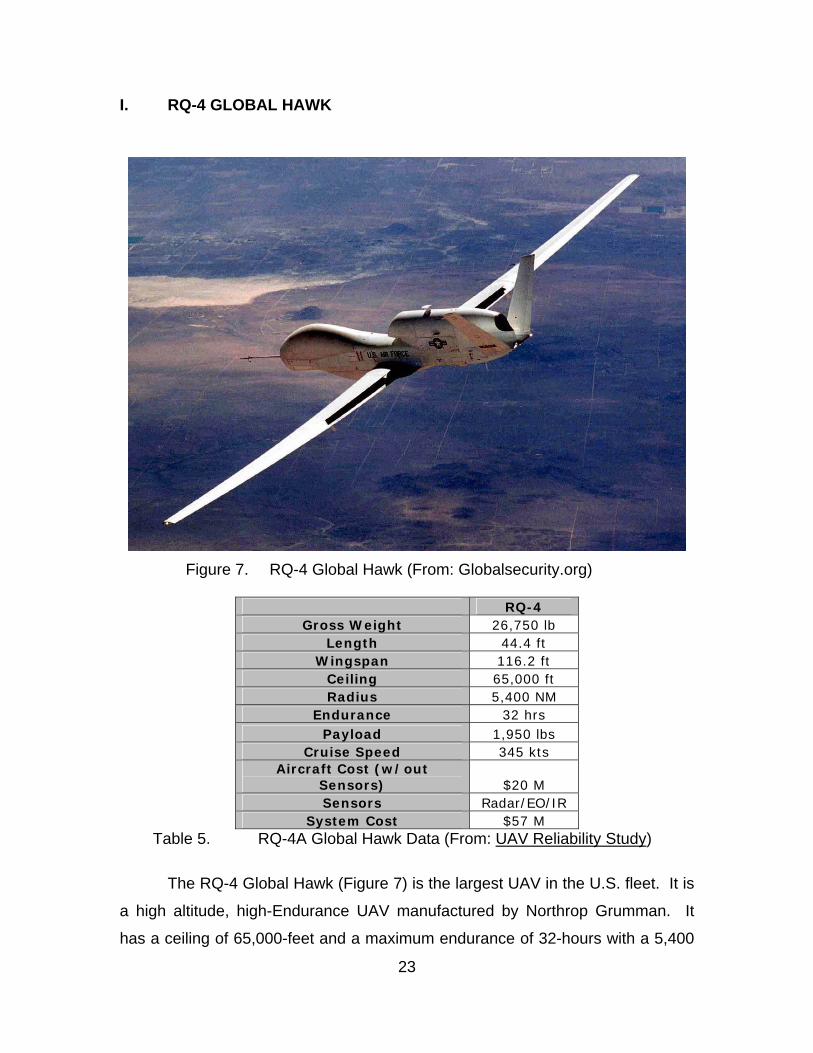
Figure 7. RQ-4 Global Hawk (From: Globalsecurity.org)
RQ-4
Gross Weight 26,750 lb Length 44.4 ft
Wingspan 116.2 ft Ceiling 65,000 ft Radius 5,400 NM
Endurance 32 hrs Payload 1,950 lbs
Cruise Speed 345 kts Aircraft Cost (w/out
Sensors) $20 M Sensors Radar/EO/IR
System Cost $57 M Table 5. RQ-4A Global Hawk Data (From: UAV Reliability Study)
The RQ-4 Global Hawk (Figure 7) is the largest UAV in the U.S. fleet. It is
a high altitude, high-Endurance UAV manufactured by Northrop Grumman. It
has a ceiling of 65,000-feet and a maximum endurance of 32-hours with a 5,400

24
NM range. The aircraft has a length of 44.4-feet and a wingspan of 116.2-feet.
The Global Hawk can carry both radar and an electro-optical/infrared (EO/IO)
payload at the same time. It can carry a total payload of 1,950-pounds. It is
controlled through either line-of-sight or KU-band Satcom for beyond line-of-sight
communications.
Although the Global Hawk has not yet reached Initial Operational
Capability (IOC), it has been used to support Operation ENDURING FREEDOM.
The Global Hawk aircraft costs $20 million, with a complete system costing a
total of $57 million (OSD Reliability 18). The Global Hawk aircraft can be based
in a theater or in the United States. The system requires a long runway for take-
off and for recovery of the aircraft. The complete system is composed of air
vehicles, the sensor and payload gear, avionics and data links, a ground-based
Launch and Recovery Element (LCE), a Mission-control Element (MCE), a
support element, and the personnel required to maintain and to operate the
system. The MCE is not required to be in the area of the LCE, allowing the
aircraft to be controlled from a distance. The Global Hawk can be controlled
remotely from the United States while it is over a target in another hemisphere.
The Global Hawk system is capable of linking with current and future planned
intelligence systems in order to distribute data across the battlefield and back to
the Continental United States.
25
J. FMQ-151 POINTER
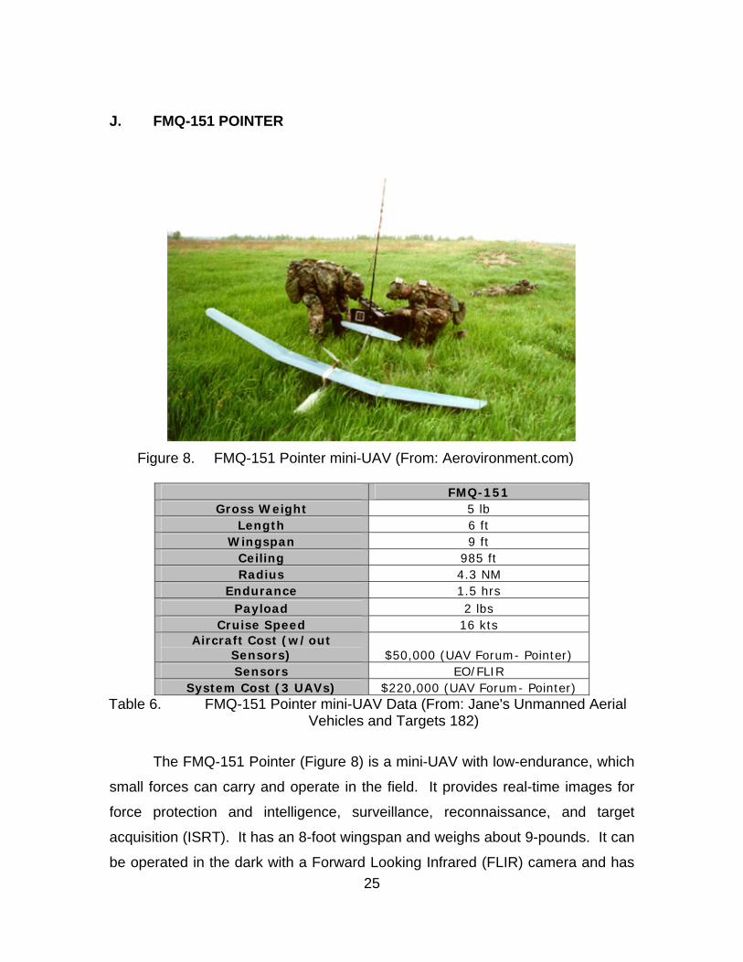
Figure 8. FMQ-151 Pointer mini-UAV (From: Aerovironment.com)
FMQ-151
Gross Weight 5 lb Length 6 ft
Wingspan 9 ft Ceiling 985 ft Radius 4.3 NM
Endurance 1.5 hrs Payload 2 lbs
Cruise Speed 16 kts Aircraft Cost (w/out
Sensors) $50,000 (UAV Forum- Pointer) Sensors EO/FLIR
System Cost (3 UAVs) $220,000 (UAV Forum- Pointer) Table 6. FMQ-151 Pointer mini-UAV Data (From: Jane's Unmanned Aerial
Vehicles and Targets 182) The FMQ-151 Pointer (Figure 8) is a mini-UAV with low-endurance, which
small forces can carry and operate in the field. It provides real-time images for
force protection and intelligence, surveillance, reconnaissance, and target
acquisition (ISRT). It has an 8-foot wingspan and weighs about 9-pounds. It can
be operated in the dark with a Forward Looking Infrared (FLIR) camera and has
26
a mission time of about 90-minutes. The system is composed of three vehicles
and a ground-control station. It is a hand-launched vehicle that lands in a
controlled crash, not unlike many mini-UAVs. It has a maximum altitude of
3,000-feet and a speed of 43-knots. It is powered by rechargeable Nickel
Cadmium (NiCd) or Lithium (Li) batteries and can carry a payload of two pounds
(UAV Forum- Pointer). It has a radius of 1 to 3 NM. The vehicle is priced at
$50,000 dollars per aircraft. The system of three aircraft, the GCS, and
supporting payloads costs $220,000.
This system has had extensive use with special operations forces over the
course of Operation ENDURING FREEDOM ("MAV- Combat Lessons Learned").
The Pointer is used to support ground forces. These forces will require more
than one flight to support the duration of their missions. The 90-minute
endurance of the Pointer aircraft ensures that the three-man crew is constantly
preparing, launching, and recovering one of the three aircraft to support the
ground forces with persistent information.
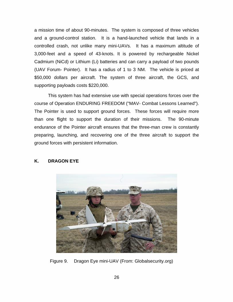
K. DRAGON EYE
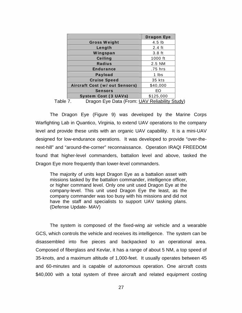
Figure 9. Dragon Eye mini-UAV (From: Globalsecurity.org)
27
Dragon Eye
Gross Weight 4.5 lb Length 2.4 ft
Wingspan 3.8 ft Ceiling 1000 ft Radius 2.5 NM
Endurance .75 hrs Payload 1 lbs
Cruise Speed 35 kts Aircraft Cost (w/out Sensors) $40,000
Sensors EO System Cost (3 UAVs) $125,000
Table 7. Dragon Eye Data (From: UAV Reliability Study) The Dragon Eye (Figure 9) was developed by the Marine Corps
Warfighting Lab in Quantico, Virginia, to extend UAV operations to the company
level and provide these units with an organic UAV capability. It is a mini-UAV
designed for low-endurance operations. It was developed to provide “over-the-
next-hill” and “around-the-corner” reconnaissance. Operation IRAQI FREEDOM
found that higher-level commanders, battalion level and above, tasked the
Dragon Eye more frequently than lower-level commanders.
The majority of units kept Dragon Eye as a battalion asset with missions tasked by the battalion commander, intelligence officer, or higher command level. Only one unit used Dragon Eye at the company-level. This unit used Dragon Eye the least, as the company commander was too busy with his missions and did not have the staff and specialists to support UAV tasking plans. (Defense Update- MAV)
The system is composed of the fixed-wing air vehicle and a wearable
GCS, which controls the vehicle and receives its intelligence. The system can be
disassembled into five pieces and backpacked to an operational area.
Composed of fiberglass and Kevlar, it has a range of about 5 NM, a top speed of
35-knots, and a maximum altitude of 1,000-feet. It usually operates between 45
and 60-minutes and is capable of autonomous operation. One aircraft costs
$40,000 with a total system of three aircraft and related equipment costing
28
$125,000. The payloads can provide full motion color and low-light video. The
aircraft requires a LOS data link to maintain control. Future payloads are
planned to increase its capabilities.
L. DESERT HAWK
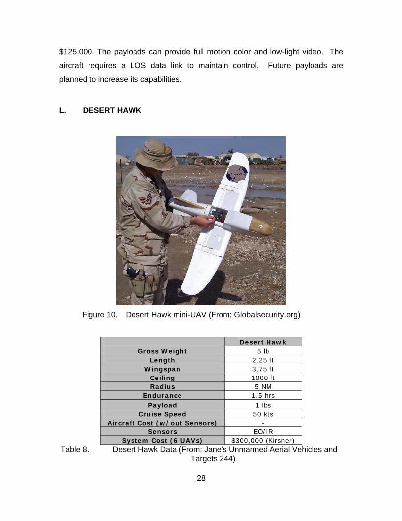
Figure 10. Desert Hawk mini-UAV (From: Globalsecurity.org)
Desert Hawk Gross Weight 5 lb
Length 2.25 ft Wingspan 3.75 ft
Ceiling 1000 ft Radius 5 NM
Endurance 1.5 hrs Payload 1 lbs
Cruise Speed 50 kts Aircraft Cost (w/out Sensors) -
Sensors EO/IR System Cost (6 UAVs) $300,000 (Kirsner)
Table 8. Desert Hawk Data (From: Jane's Unmanned Aerial Vehicles and Targets 244)
29
The Desert Hawk (Figure 10) is a mini-UAV with low-endurance used
extensively during Operation ENDURING FREEDOM to protect forces via
airborne surveillance. The aircraft has a 4-ft wingspan and can take off in a small
field using a 300-ft bungee cord system that requires a two-man crew. The
system transmits real-time video to a laptop operated by the controller up to a
range of about three miles. The Desert Hawk can store waypoints and can
update these waypoints during flight. Each kit comes with six aircraft, a GCS and
a remote video terminal. The complete system costs $ 300,000 (Kirsner). The
control system is limited to operating one aircraft at a time. The Desert Hawk
incorporates an interchangeable payload allowing both day and night cameras as
well as infrared capability. The system is powered by rechargeable batteries and
can remain aloft for one hour, cruising between 35 and 52 knots at an altitude of
about 500 feet.
M. UAV PRODUCT DISSEMINATION
UAVs are controlled through the GCS and MCE that can be located in the
immediate vicinity, local area, local region, theater or even as far away as the
United States depending on the system. Systems capable of being controlled
through a KU-band satellite link and that have greater range, such as the Global
Hawk, are usually operated from the United States. Information is passed from
either the GCS or the MCE to the Service Distributed Common Ground System
(DCGS) (Unmanned Aerial Vehicle Roadmap 166). The DCGS is a group of
standards that address Tasking, Posting, Processing and Usage (TPPU)
requirements in order to facilitate interoperability between the stovepipe systems
of the individual services. The DCGS architecture integrates all of the data so
that each service can use its legacy systems to access common data. The link
to the DCGS commonly occurs at the control station of the UAV. The DCGS is a
preliminary step to the Global Information Grid (GIG), the use of which will
increase systems integration and throughput capacity.
30
The link to the DCGS allows the intelligence centers to collect the data
and produce products for dissemination. Tactical users cannot always
immediately exploit the intelligence they receive because some level of analysis
must occur in order to decipher the information received. It would be useful for
tactical users to be able to receive and interpret the data from a UAV
immediately. Unfortunately, not all data can be accurately framed without an in-
depth background in intelligence interpretation. Immediate exploitation of UAV
data requires the user to interpret the data quickly and accurately. There is a
high likelihood that some data transmitted directly to the tactical user may be
misinterpreted, or that the user will have insufficient knowledge of the complete
situation in order to interpret the data.
The tactical users at the company level and below are mostly concerned
with real-time intelligence in their local area. Mini-UAVs provide the portability
needed to support small units of operation with timely information, which
intelligence experts can then interpret. Inexperienced commanders should not
control some of the capabilities that are being researched because they will not
be able to appropriately employ these assets. For example, a tactical unit should
not operate an electronic warfare platform without the knowledge needed to use
these assets properly. Tactical users should focus on collecting and interpreting
any data and images that can be used immediately. Specialized units should
collect any data that are not applicable to the tactical user and then forward the
data to intelligence centers for interpretation and dissemination.
N. SUMMARY UAVs offer a platform to perform “dull, dirty, and dangerous” missions
(Unmanned Aerial Vehicle Roadmap 27). UAVs are less expensive to maintain
and operate that most manned aircraft. They allow collection of vital intelligence
data when it would be dangerous for a manned aircraft, but they are still
susceptible to the same factors as any other type of aircraft. Wind, sand, icing
and other environmental factors limit their ability to fly and to collect useful data.
31
There is a vast amount of information on UAV systems, however a great
deal of this information is either incorrect or limited in its usefulness. Experience
with UAVs develops the understanding needed to employ these assets properly.
Each system is capable of performing different types of missions with varying
degrees of success. Payloads vary in quality and complexity and some aircraft
perform better than others. Experience reveals the capabilities and limitations of
individual systems. This knowledge is necessary to optimizing the use of these
limited resources.
The development of future UAV systems strives to increase the
capabilities of these units and increase the reliability of these systems; however
there will always be limitations. Each specific aircraft has its own unique set of
limitations and capabilities. Attainment of this knowledge will increase the
effectiveness of these assets through their correct employment.

32
THIS PAGE INTENTIONALLY LEFT BLANK
33
III. MINI-UAVS
A. INTRODUCTION The 2002 Department of Defense (DOD) Unmanned Aerial Vehicle
Roadmap considers a number of capabilities for larger UAV systems, however
not all of these missions can be considered effective allocation of resources for
mini-UAVs due to their limited capabilities and time aloft. Miniaturization of
payloads will open up a wider variety of applications for mini-UAVs by allowing
them to carry more than one type of sensor. The current level of technology
limits payloads to performing one type of mission during a flight. Interchangeable
payloads extend the mission range of these systems, but they must return to the
ground to be replaced. Larger systems, such as the Global Hawk, currently
provide the capability to equip the aircraft with a wide variety of sensors that
allow multiple types of missions to be accomplished in one flight.
The 2002 DOD Unmanned Aerial Vehicle Roadmap identified seventeen
areas in which UAVs have been employed either through concept
demonstrations or operationally. Mini-UAVs cannot provide adequate support in
some of these areas:
• Intelligence, Surveillance, & Reconnaissance (ISR)
• Command and Control (C2)/ Communications
• Force Protection (FP)
• Signals Intelligence (SIGINT)
• Weapons of Mass Destruction (WMD)
• Theater Air and Missile Defense (TAMD)
• Suppression of Enemy Air Defenses (SEAD)
• Combat Search and Rescue (CSAR)
• Mine Counter Measures (MCM)
• Meteorology and Oceanography (METOC)
• Counter Narcotics (CN)
• Psychological Operations
34
• All Weather/ Night Strike
• Exercise Support
• Counter Fire
• Anti-Submarine Warfare
• Navigation
B. MINI-UAV FACTORS 1. Mini-UAV Planning/ Preflight Mini-UAVs are envisioned as being rapidly available to a commander, yet
there are still considerations that must be taken into account before a mini-UAV
mission. Thorough planning must be undertaken to ensure that the aircraft will
be operated safely. Even though mini-UAVs are of low cost, and can be
considered expendable, care must still be taken to bring as many back as
possible. The possibility of mini-UAVs causing damage and loss of life to our
own troops exists if they are not operated with caution.
Planning must be undertaken to ensure that the mini-UAV is operated with
the best consideration of winds and other environmental factors, launch position,
mission profile, mission objectives, integration into the airspace, and landing.
This includes defining the separation of UAVs with manned aircraft and the entry
and exit procedures over the target area. Mini-UAVs must be integrated into the
airspace over a target area to provide time or altitude separation from other
aircraft. The small size of these vehicles limits the ability of pilots of manned
aircraft to maintain visual separation. Mini-UAVs offer little situational awareness
to the operator, so it becomes hard for the UAV pilot to maintain visual
separation. The possibility of installing a transponder system is unlikely for the
foreseeable future due to the small payload size that these units are capable of
carrying.
A thorough preflight must be performed to verify that all systems are
working correctly. Mini-UAVs seldom include any system redundancy. Each
system becomes a single point of failure and each must work in unison to ensure
35
that the aircraft can fly and perform its mission. If the control link fails, the UAV
will usually have a return-to-base feature guided by Global Positioning System
(GPS) data; however, if the motor, electrical system, data link, or avionics/
control system fails then the aircraft will become unusable. Any problems in the
preflight must be corrected before the aircraft can fly, or the mission will not
succeed and the UAV will likely be lost or destroyed.
The planners must consider the entire mission before the aircraft has left
the ground. While this planning may occur rapidly, it must be comprehensive in
order to operate the aircraft safely. The planning must consider the full
capabilities and limitations of these vehicles. Although they are designed to be
expendable, treating them as such is not wise. The limits of these craft may be
tested if it is of operational necessity; however, the commander must be willing to
assess the costs and benefits of losing his "eye" in the sky.
2. Time Aloft/ Loiter Time Larger UAV systems have significantly longer loiter times to survey a
target area. The Global Hawk can remain aloft for over 32 hours. Larger UAVs
also require improved areas for take-off and landing. The lack of runways in
proximity of tactical units restricts the ability to locate UAVs nearby. Even if they
can be located near the troops they are supporting, this is not a judicious option,
as their logistical bases are not rapidly mobilized, and these systems are tied to
runways. The probability of destruction by enemy fire increases as these units
are stationed closer tactical units.
Mini-UAVs provide short times aloft, generally in the range of thirty
minutes to one hour and thirty minutes. Surveillance using mini-UAVs cannot be
conducted over the period of a lengthy operation without multiple UAVs and
without a crew experienced at launching and recovering UAVs continuously.
Time to reach the target area must be factored into the calculations of the UAV
availability over the area.
36
The ability to support retasking of these assets is also minimal, for they
might not have the capability to accomplish sustained operations. Mini-UAVs
must be considered as platforms used to perform a specific mission at a specific
time. These missions can be rapidly formed, but these platforms should not be
seen as persistent surveillance platforms. They should be seen as platforms
used to answer specific questions or address specific threats.
3. Ability to Launch The ability to launch the UAV is vital to its employment. Most mini-UAVs
do not require a runway or any type of improved surface for launching, but they
do require an open field or drop-off in which to transition to flight. A general area
about the size of a football field should be used. Mini-UAVs cannot be operated
directly on the front lines safely. The requirements for launch of current systems
require some isolation from direct fire. Soldiers must be able to stand up and
launch the systems by hand. The Dragon Eye system requires at least two
people and a long bungee cord to launch the system, leaving the launch crew
exposed (Grimes). Therefore, this is not yet a system that can be launched in
the direct vicinity of combat.
Instead of launching at the front, these units must be launched away from
the rear of the combat area. The situation will dictate how far from the front lines
mini-UAVs must be launched. Locating the UAV GCS away from the
commander and troops intent on using data from the UAV introduces
coordination issues. With the GCS in the rear it is hard to direct the UAV and
obtain data from it.
4. Wind and Atmospheric Conditions Moderate winds are a large hindrance to the operation of mini-UAVs due
to their small design. In high winds, the aircraft will tend to become less stable
and thus the cameras and sensors will lose effectiveness for live video feeds.
Using still images under these conditions is possible.
37
Mini-UAVs are launched into the wind in order to supply the lift needed
until their motors can provide the thrust necessary for flight. Light winds allow
the user to choose a direction of flight in which to launch the UAV for optimal
operational utility. Of course, moderate winds can drastically affect the ability of a
Mini-UAV to launch in an optimal direction.
We are only limited by the weather and battery life. The environment here [in Iraq] makes it tough to fly, especially (in) the wind. Getting the plane airborne, keeping it on track and (landing) in a safe place when it's done (are) probably the hardest (parts) of the (Desert Hawk) mission. (qtd. in Nelson)
Winds will also affect the direction of launch of the UAV, as well as its
ability to maneuver around a target. Moderate to high winds with the target
upwind of the launch point will hinder operations to reach the target site, as mini-
UAVs typically have small motors and a limited top speed.
Moderate winds reduce the ground speed of the mini-UAV and may
overpower the mini-UAV. In high winds, smaller control surfaces also have less
ability to maintain the direction and stability required to fly the aircraft. The
aircraft is more susceptible to wind gusts and other phenomenon that can wreak
havoc on the aircraft.
Other environmental conditions impact the usefulness of these mini-UAVs
during operations. Icing can cause control surfaces to loose effectiveness and
add weight to the airplane causing a decrease in lift and possibly a loss-of-control
situation. Mini-UAVs do not have the systems required to fly through conditions
that might cause ice to form on lift and control surfaces. Systems that combat
icing add complexity and cost to these units and are not necessary in most
operational scenarios.
The use of mini-UAVs during rain and snow is not generally
recommended. Moisture can damage the electrical systems and cause the UAV
to crash. Mini-UAVs have few provisions for protection from the elements.
Flight during light rain and snow might be possible, but is not recommended.

38
5. Density Altitude Density altitude describes what the air feels like to an aircraft in relation to
a standard atmospheric day (15°C and 29.92 in. of mercury at sea level). As
temperature increases, the air molecules move fast and further apart. This
creates a thinner, less dense atmosphere when compared to a lower
temperature at the same altitude. Air density directly affects the lift that can be
produced from an aircraft. As the air density decreases, the density altitude
increases, and the ability to generate lift decreases. In mini-UAVS this can be a
problem, as they are not designed to fly in extreme conditions. Mini-UAVs are
generally not designed to fly at high altitudes. A high density altitude causes the
aircraft to fly as if it were at that altitude. This can limit the availability and utility
of mini-UAV operations.
6. Temperature The temperature does not just affect the density altitude. Electrical
components need to be cool to operate properly. Extreme environments affect
all of the systems on-board the aircraft. Overheating can cause components to
fail either before take-off or during flight. Generally failure will take place before
the preflight. During flight components are cooled as air passes over them.
An operational fix for this deficiency might be the employment of small
fans used to cool computers. These fans are light and draw very little amperage.
They could easily be added internal to the UAV to cool components. The lack of
an ability to operate in high temperatures means that operations in high
temperature environments are affected. Individual systems are composed of
different grades of components that can handle different temperatures. The
effects of heat may vary between different models of mini-UAVs.
7. Operations in Dense Areas/ Over-the-Horizon Mini-UAVs require direct line-of-sight between the ground-control station
and the aircraft. Any objects in the way will absorb, scatter, or reflect the weak

39
control signals and cause the UAV to become uncontrollable. The ground-control
station antennas must be placed high above any obstruction. Buildings, dense
forested areas, and other structures will not permit the weak control signals to
reach the aircraft. Figure 11 illustrates the shadow zone that is created by
obstructions. In the figure the obstruction limits the UAV from operating at low
altitudes around the city and the factory. As the UAV goes further from the
ground control station it must maintain a higher altitude to overcome the
curvature of the earth and the shadow zone created by the obstruction.
Figure 11. UAV Line-of-sight Control Link Limitations
The placement of the GCS is an important consideration.
Mini-UAV GCS are integrated units that contain the mission-planning software
and the transmission equipment necessary to interface with the mini-UAV under
flight. Consideration of the operating area must be taken into account. The flight
path of the aircraft must be considered before a site is chosen on which to erect
the ground-control station and supporting equipment.

40
8. Number of People to Operate Operating mini-UAVs typically requires one to two people. Launch and
recovery may require more. The technology readiness level (TRL) of mini-UAVs
is presently low, but future vehicles will be able to perform most missions on their
own (Unmanned Aerial Vehicle Roadmap 131). The TRL is used to "assess the
maturity of evolving technologies prior to incorporating that technology into a
system or subsystem" ("Technology Readiness Level"). One component relating
to an increase in the TRL is autonomy. Autonomy is the ability of a unit to
operate without input from a human.
A UAV with some level of autonomy is in the near future; however, the
utility that can be gained will be minimal. The required level of autonomy to allow
a fighting troop to operate and to gain information from a mini-UAV will have to
be very high. A troop must be able to task the UAV and receive information from
the unit quickly and directly without the need to operate the UAV. At this point in
time mini-UAVs must have dedicated crews to perform their mission. Keeping
these people from danger is important, since they must concentrate on the
operation of the UAV, rather traditional combat operations. Yet, they must still be
located near the commander to relay pertinent information, or have a direct
means of communication with the commander.
9. Communications Security The nature of COTS technology defines the components as mostly COTS
as well. Most mini-UAV manufacturers are technology integrators who purchase
equipment from other vendors in order to develop a system. The components
are mass-produced by these companies. Mass production drives down the cost
of the individual components and the total system. Although lower cost is a
benefit, the mass production of the components means they can be purchased
and easily used to reverse engineer a system. Components can be of hobby-
grade or of military-grade.

41
Hobby-grade components do not ensure security. If the adversary could
obtain one of the systems it would be easy to reverse engineer the complete
system. Since the components could easily be bought through COTS venders,
specifications and parts to recreate the system could readily be obtained. It is
possible that the enemy could reverse engineer the data link and the control link.
The enemy would then have the opportunity to monitor the use of the mini-UAV
or even take control of the unit. Subsequent development of mini-UAVs should
concentrate on developing more secure control and data links between the
ground-control station and the mini-UAV.
Commercial venders must accept the requirement for these secure data
links and work to develop them. The military can refuse to buy any system that
does not have a secure data link, but they must be willing to endure the increase
in cost to obtain these systems.
10. Frequency Separation A major concern with mini-UAVs is the loss of control link. If the control
link is lost the aircraft cannot be controlled from the ground-control station. An
aircraft operating in autonomous mode will continue upon its intended flight path,
but if the control link and the data link are combined, the user will not be able to
obtain any data from the aircraft. The lack of onboard storage will mean that the
flight was unsuccessful. A larger problem will occur if the aircraft is in manual
mode. Most systems will cause the aircraft to return to a defined point when the
control-link is lost. The loss of the control-link still results in the mission being
unsuccessful.
A major problem with the control link is interference with other systems on
nearby frequencies, or interference due to flying through an area with too many
transmitters. The radio frequencies (RF) in an area of operation must be
considered and steps must be taken to keep the control and data link frequencies
clear of other traffic. Mini-UAVs concentrate on the use of Commercial-off-the-
Shelf integration in order to cut down costs. Most of these units use similar
42
frequencies for control and data links. If adversaries were sufficiently prepared
they could easily use other devices to jam these non-secure control and data
links.
11. Tie-in to the Information Grid The ability to tie into the information grid is a key component to passing
data to the higher levels of command.
At least 100 UAVs of 10 different types were used in OIF yet none of them allowed integrated direct data receipt. To date, individual Services have been reluctant to adopt common mission management systems or other interoperability approaches within similar types or classes of UAVs. Each Service has tended to initiate its own separate development program specifically tailored to its requirements rather than adopting an existing capability from another Service. (Defense Science Board x)
Video, still images, and other data collected from mini-UAVs can provide greater
situational awareness to local users and higher-level commanders if they are
shared with those higher-level commanders. Mini-UAV ground-control stations
are not bound by any set of standards. The data and control links between
different systems are not interoperable. The larger UAV systems are currently
dealing with this problem, but most of these systems have been developed under
some type of government contract so they incorporate some common standards
(Unmanned Aerial Vehicle Roadmap 135). The standardization of the interfaces
for these UAVs is a significant problem that is being examined.
COTS systems present a different problem when trying to deal with
developing and enforcing standards. The components in these systems can be
similar because they are obtained from other COTS manufacturers. Yet even if
the components are similar, companies will have different interfaces with their
units to attempt to distinguish their systems from competitors. These interfaces
are not interoperable. Some COTS manufactures are not interested in
developing systems that interface with other systems, instead they are interested
in developing stand-alone systems and the impetus for integrating these systems
into the intelligence networks must fall on the user.
43
This data sharing hinges on the ability of the UAV ground-control station to
connect to military information systems. It also requires a great deal of
bandwidth to support full-motion video and other live products. At this time,
connection to the GIG may restrict the mobility of the GCS. It also requires the
ground-control station be located near assets that are already connected to the
global information grid. Distribution to users over the "last tactical mile" from
GIG access points to soldiers on the ground is a problem that needs to be
solved. The development of systems that allow individual users to connect to the
global information grid will increase the mobility of soldiers. It will, in turn,
increase the mobility of mini-UAV ground stations connected to the global
information grid.
12. Landing Due to the small size and mass of mini UAVs, these units do not possess
a great deal of momentum at any point during their flight. Most mini-UAVs land
in a controlled crash. The engine is shut down and the aircraft is allowed to glide
into the ground. If this procedure is performed incorrectly, varying amounts of
damage can occur, depending upon the surface and the speed of the UAV and
the construction of the unit. Most damage can be repaired through the use of
spare parts.
13. Field Support Requirements Mini-UAV systems can be considered expendable due to their inexpensive
cost, but they should not be treated as such. These units are often easily
repaired by non-technical people through the use of spare components without
any mechanical or technical training requirements. All of the components in
these units must be operational before launch. A good preflight inspection and
testing of the systems will ensure this is the case. When there is a problem the
parts can quickly be interchanged from a small inventory of on hand parts. The
simplicity of these systems even allows the use of duct-tape to hold together
44
broken body parts. This inventory is not much of a burden on the individual
soldier because the parts are small.
C. MINI-UAV SPECIFIC MISSIONS A solid understanding of UAVs must underlie any decision to employ
these assets. The 2002 Unmanned Aerial Vehicle Roadmap defines a wide
range of missions in which UAVs can perform, but UAVs might not be the best
option for some missions. A commander must consider all of his assets before
selecting a particular course of action. The tendency is to call on UAVs before
considering other solutions. The “wow” factor involved in UAV operations has
created a syndrome in which inexperienced people believe that flying a UAV
above any area will bestow “everything to everyone.” The limitations of these
assets are not considered.
Mini-UAVs are prone to this phenomenon. Operational experience with
these UAVs leads to better understanding and employment of these assets. The
Defense Science Board Task Force on UAVs found that, "operational experience
with Predator, Global Hawk, Hunter, and special purpose UAV systems during
recent conflicts demonstrated that, once employed by warfighters, the value of
UAVs becomes immediately evident, ideas for new operational concepts are
spawned, a constituency is formed, and strong advocacy begins to build" (9).
Mini-UAVs are still under development and most commanders do not have a
clear understanding of their limitations. In the future it will be possible for mini-
UAVs to participate in all the missions defined by the 2002 Unmanned Aerial
Vehicle Roadmap, but like all aircraft they will still have constraints on their
operation.
Miniaturization of current technology will give mini-UAVs robust
capabilities. The ability to perform electronic warfare and information operations
will be available in the future. Other developments will greatly enhance the ability
to collect and to disseminate intelligence data. The DOD must ensure that it
does not lose sight of the employment limitations of these vehicles. Some
45
capabilities that are implemented in larger UAVs have no place in the smaller,
mini-UAV systems. The basic factors of their employment must be considered.
Technology must not dictate the mission. Conversely, the mission should dictate
the appropriate technologies that should be developed for these units. Small
tactical units, devoid of specialized training, should not employ mini-UAVs with
capabilities beyond EO and IR.
Mini-UAVs should be treated the same as larger manned systems they
intend to replace. Signals intelligence, anti-submarine warfare, and detection of
weapons of mass destruction are all areas in which specially trained personnel
are needed to manage collection and interpretation of data. Typical military units
do not have the training or manpower to process and disseminate this data
accurately. Units dedicated to these areas of expertise must be used if there is
to be any gain from the use of these mini-UAVs. With this in mind, the greatest
utility for mini-UAVs is in furnishing regular unit commanders with intelligence
data that require rudimentary analysis and simple missions. These missions
include: Intelligence, surveillance, and reconnaissance, C2/ communications,
force protection, combat search and rescue, and navigation. Still, the limitations
of these units must be considered in relation to other available assets before they
are used.
1. Intelligence, Surveillance, and Reconnaissance (ISR) Intelligence, Surveillance, and Reconnaissance (ISR) is the classic
mission associated with UAVs. A variety of different payloads support this
capability and all current UAVs have some form of ISR capability. ISR collection
and distribution can include EO/IR full motion and still imagery. Smaller UAVs
are readily capable of ISR collection for immediate exploitation by ground troops.
This is a vital asset for small forces allowing an “Over-the-Hill” or “Around-the-
Corner” capability.
ISR is arguably the most valuable type of information that mini-UAVs can
collect. Due to their small size and limited range, they are well situated to
46
operate in and around a small force. They don't require higher headquarters
tasking, and can be launched immediately, whereas larger systems need to
coordinate with other air assets. Despite their relative ease of use, a surveillance
technician must constantly monitor the data feed from these units so that
intelligence can be gleaned from the raw feed. There is a tendency to believe
that anyone can interpret data from a UAV, but skilled interpreters must be
available to interpret any obscure or confusing information.
The military is being asked to participate in situations that are not usually
in the realm of pure military operations. These operations Other Than War
require background knowledge for the interpretation of the data to be collected.
Interpretation of situations without the knowledge of an experienced intelligence
analyst could lead to fatal or faulty decisions. Trained intelligence analysts must
be in the vicinity of the data feed to ensure that the information gained from mini-
UAVs is interpreted correctly, unless it is possible to pass the data quickly to a
remote-site analyst and receive rapid feedback on the information being
collected. This would rely on a secure and robust connection to the global
information grid.
2. Force Protection Force protection is a primary mission for mini-UAVs. All of the current
mini-UAVs are being used for this mission. Force protection includes perimeter
patrol of bases as well as scouting out convoy routes prior to troop/vehicle
passage. Mini-UAVs provide an excellent capability because it is not difficult to
schedule these aircraft or prepare them for flight. One drawback is that very little
automation of detection technologies exists onboard mini-UAVs. Operators must
monitor video and sensor feeds to ensure that the appropriate data are captured,
intelligence derived, and that the commander can be alerted.
47
3. C2/ Communications UAVs have been shown to be capable of linking ground forces where LOS
bands do not reach. A UAV with a relay radio inside is able to act as a repeater
station. If both units can see the UAV, but not each other then they can talk
through the UAV with this repeater capability.
Use of a weaker source RF signal and then a UAV to boost the signal and overcome LOS restrictions can help to reduce an enemy's ability to use the direction of arrival of an intercepted signal to locate the position of a ground unit, command post, etc. This can increase the security of our communications, but more significantly, the physical security of the communicator. (Fisher)
The use of UAVs as communications nodes for extending communications
distances is better left for larger systems. While mini-UAVs are able to provide
repeater communications over a small area, they cannot power transmissions to
connect distant units. Mini-UAVs do not currently have the ability to lift and
transport radios large enough to fill the necessary capability gap to fill a vital
mission role in this area. The size of the radios necessary to link
communications would limit the mini-UAVs ability to carry other equipment and
would reduce its time aloft. Power requirements would also limit the total time
aloft, reducing the effectiveness of this capability and making it more of a
hindrance to operations than a force enabler. Miniaturization of electronics will
expand the capability of mini-UAVs to perform this mission in the future. The
Special Operations Forces believe that this capability will enable them to operate
more effectively in the field (Howard 53).
4. Navigation Mini-UAVs could determine reference points for navigation. The ability to
obtain a bird’s eye view of the current location of forces as well as the rivers,
mountains, road intersections, and enemy forces can help one decipher locations
on maps as well as provide directions and distance. The GPS signal requires at
least three satellites for a two dimensional (2D) fix. The latitude and the
48
longitude are reported in a 2D fix; however, altitude data is not reported.
Canyons, mountains, and atmospheric disturbances can degrade a GPS
receiver's accuracy. UAVs might obtain GPS through their avionics systems by
rising above the terrain or elemental restrictions of a particular area. This is a
particularly good mission for mini-UAVs because it can be accomplished while
the mini-UAV is conducting other missions and does not require a special
payload.
5. Combat Search and Rescue (CSAR) Mini-UAVs are well suited for conducting Combat Search and Rescue
(CSAR). They could be used to search for units isolated from the rest of the
platoon or squad. They could also be used to locate downed pilots. These units
are uniquely qualified to loiter over hostile areas and search for missing
personnel. Mini-UAVs remove humans from the danger of flying over a hostile
area while providing an aerial asset to search for missing personnel.
Once these personnel are located, the UAV can support rescue
operations. These unmanned, expendable units can even be used to search the
most dangerous areas. Their small size makes them difficult for the enemy to
target. These units allow personnel on the ground coverage over large area in a
short amount of time. The speed of the mini-UAV allows it to cover more
distance than a human on the ground. The aerial viewpoint also makes it easy to
locate wreckage that might be missed on foot. The use of multiple, coordinated
UAVs could offer effective CSAR over an area.
D. LOCAL PERSISTENCE The problem with current large UAV systems and the policy that governs
their use is that data and intelligence rarely make it to the tactical users in time
for them to use. This is not only a problem related to UAV systems. Tactical
users have trouble interacting with any type of intelligence system due to their
high mobility and the lack of robust systems to support them while mobile.
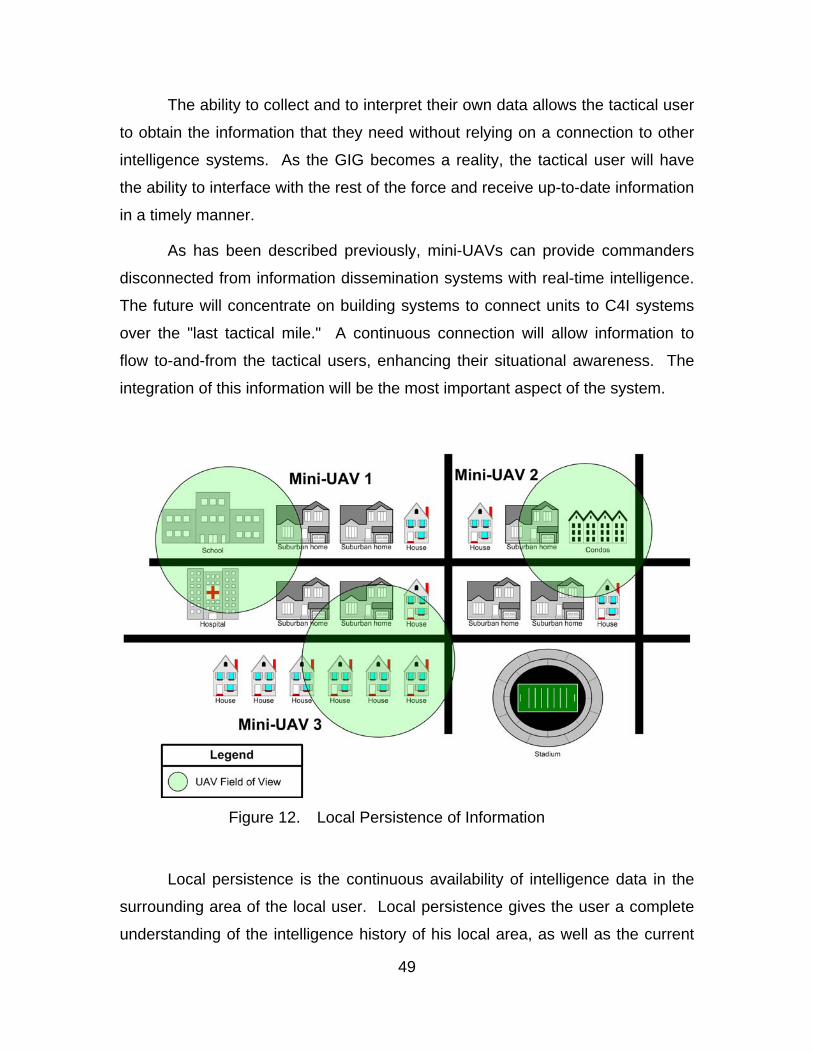
49
The ability to collect and to interpret their own data allows the tactical user
to obtain the information that they need without relying on a connection to other
intelligence systems. As the GIG becomes a reality, the tactical user will have
the ability to interface with the rest of the force and receive up-to-date information
in a timely manner.
As has been described previously, mini-UAVs can provide commanders
disconnected from information dissemination systems with real-time intelligence.
The future will concentrate on building systems to connect units to C4I systems
over the "last tactical mile." A continuous connection will allow information to
flow to-and-from the tactical users, enhancing their situational awareness. The
integration of this information will be the most important aspect of the system.
Figure 12. Local Persistence of Information
Local persistence is the continuous availability of intelligence data in the
surrounding area of the local user. Local persistence gives the user a complete
understanding of the intelligence history of his local area, as well as the current
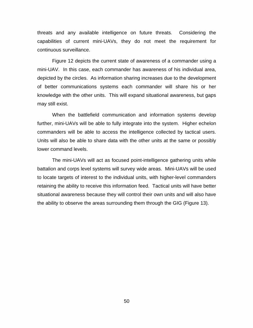
50
threats and any available intelligence on future threats. Considering the
capabilities of current mini-UAVs, they do not meet the requirement for
continuous surveillance.
Figure 12 depicts the current state of awareness of a commander using a
mini-UAV. In this case, each commander has awareness of his individual area,
depicted by the circles. As information sharing increases due to the development
of better communications systems each commander will share his or her
knowledge with the other units. This will expand situational awareness, but gaps
may still exist.
When the battlefield communication and information systems develop
further, mini-UAVs will be able to fully integrate into the system. Higher echelon
commanders will be able to access the intelligence collected by tactical users.
Units will also be able to share data with the other units at the same or possibly
lower command levels.
The mini-UAVs will act as focused point-intelligence gathering units while
battalion and corps level systems will survey wide areas. Mini-UAVs will be used
to locate targets of interest to the individual units, with higher-level commanders
retaining the ability to receive this information feed. Tactical units will have better
situational awareness because they will control their own units and will also have
the ability to observe the areas surrounding them through the GIG (Figure 13).
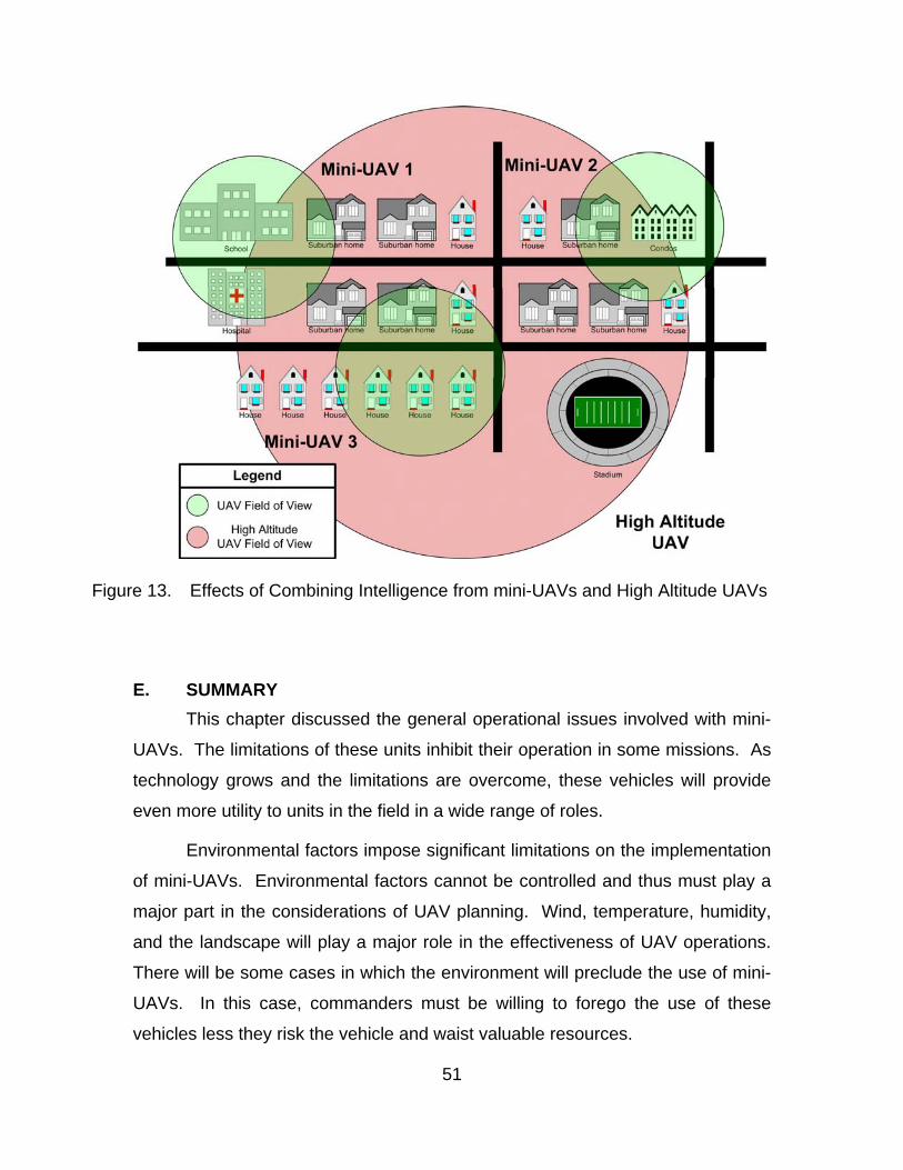
51
Figure 13. Effects of Combining Intelligence from mini-UAVs and High Altitude UAVs
E. SUMMARY This chapter discussed the general operational issues involved with mini-
UAVs. The limitations of these units inhibit their operation in some missions. As
technology grows and the limitations are overcome, these vehicles will provide
even more utility to units in the field in a wide range of roles.
Environmental factors impose significant limitations on the implementation
of mini-UAVs. Environmental factors cannot be controlled and thus must play a
major part in the considerations of UAV planning. Wind, temperature, humidity,
and the landscape will play a major role in the effectiveness of UAV operations.
There will be some cases in which the environment will preclude the use of mini-
UAVs. In this case, commanders must be willing to forego the use of these
vehicles less they risk the vehicle and waist valuable resources.

52
Missions to support tactical users are the primary use for mini-UAVs.
While these units are capable of SIGINT, COMINT, ELINT and other specialized
missions, average users do not easily employ them in this realm. Mini-UAVs
should be used for immediate surveillance applications. Little to no analysis
should be required to use the data collected from these units.
As the TRL increases mini-UAVs will become more valuable to tactical
users. The number of people required to operate the system will eventually be
reduced to support staff only. As mini-UAVs become autonomous users will only
need to input missions and then utilize the data collected by these units. The
user will not be required to control any function of the UAV, allowing him or her to
focus on fighting. Eventually, mini-UAVs might be able to determine their own
tasking. This capability is beyond the considerations of this paper, but one can
imagine a scenario in which mini-UAVs would provide persistent surveillance
across the battlefield and automatically provide targets to users.
Local persistence is a step toward global persistent ISR. Bandwidth
increases to tactical users resulting from development of the GIG will enable
local users to share ISR data and access intelligence databases. Information
can be the key to warfare. The military with perfect information can, and likely
will, dominate the battlefield.
The goal of mini-UAVs is to increase the amount of information available
to commanders at the tactical level. While persistent ISR is a ways off, the
concept of local persistence can be implemented in the near term. The next
couple of chapters will consider information sharing at the tactical level using the
COASTS network.
53
IV. COASTS PROGRAM OVERVIEW
A. INTRODUCTION The Coalition Operating Area Surveillance and Targeting System
(COASTS) program served as a test bed for integrating mini-UAVs into a rapidly
deployable network based on Commercial-off-the-shelf (COTS) technology. The
COASTS program is a model for integration of data from tactical users into the
Global Information Grid (GIG). The COASTS program provides capabilities for
individuals and small units to tie into strategic databases through a rapidly
deployable network.
B. COASTS OVERVIEW The COASTS program is researching rapidly scaleable and deployable
wireless surveillance networks based on COTS technology. The program
integrates UAVs, air balloons, portable and fixed ground-based sensors, as well
as technologies to provide situational awareness to local and strategic users.
The program is primarily concerned with supporting Direct Action, Tactical
Reconnaissance, Foreign Internal Defense, Combating Terrorism, Civil Affairs,
Counter-proliferation of Weapons of Mass Destruction, and Information
Operations (Appendix A).
The COASTS program focuses on integrating all of the data at a Mobile
Command Post (MCP) and then linking it to higher headquarters through this
node. The MCP serves as a collation point for all data arriving from the deployed
network architecture. The deployed network architecture is established through
self-meshing wireless technology that serves as an access point for users and
other assets, such as UAVs. The nodes and users connect to the deployed
access points (Breadcrumbs™) and receive a link to the integration center, the
MCP. Long-haul wireless technologies integrate other Mobile Command Posts
and link these integration centers back to higher headquarters.
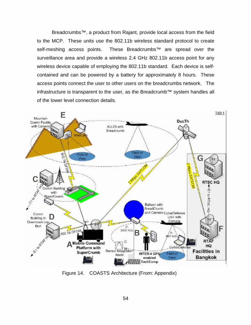
54
Breadcrumbs™, a product from Rajant, provide local access from the field
to the MCP. These units use the 802.11b wireless standard protocol to create
self-meshing access points. These Breadcrumbs™ are spread over the
surveillance area and provide a wireless 2.4 GHz 802.11b access point for any
wireless device capable of employing the 802.11b standard. Each device is self-
contained and can be powered by a battery for approximately 8 hours. These
access points connect the user to other users on the breadcrumbs network. The
infrastructure is transparent to the user, as the Breadcrumb™ system handles all
of the lower level connection details.
Figure 14. COASTS Architecture (From: Appendix)
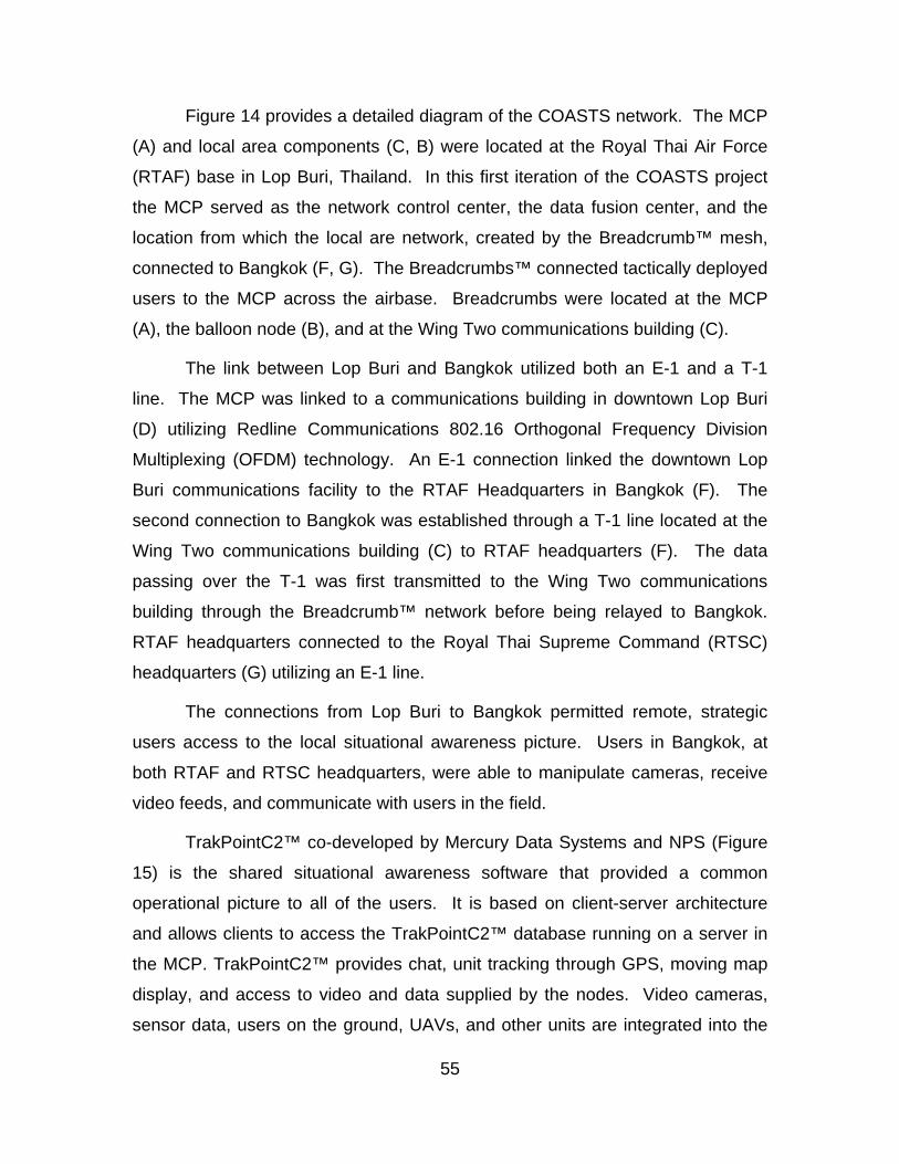
55
Figure 14 provides a detailed diagram of the COASTS network. The MCP
(A) and local area components (C, B) were located at the Royal Thai Air Force
(RTAF) base in Lop Buri, Thailand. In this first iteration of the COASTS project
the MCP served as the network control center, the data fusion center, and the
location from which the local are network, created by the Breadcrumb™ mesh,
connected to Bangkok (F, G). The Breadcrumbs™ connected tactically deployed
users to the MCP across the airbase. Breadcrumbs were located at the MCP
(A), the balloon node (B), and at the Wing Two communications building (C).
The link between Lop Buri and Bangkok utilized both an E-1 and a T-1
line. The MCP was linked to a communications building in downtown Lop Buri
(D) utilizing Redline Communications 802.16 Orthogonal Frequency Division
Multiplexing (OFDM) technology. An E-1 connection linked the downtown Lop
Buri communications facility to the RTAF Headquarters in Bangkok (F). The
second connection to Bangkok was established through a T-1 line located at the
Wing Two communications building (C) to RTAF headquarters (F). The data
passing over the T-1 was first transmitted to the Wing Two communications
building through the Breadcrumb™ network before being relayed to Bangkok.
RTAF headquarters connected to the Royal Thai Supreme Command (RTSC)
headquarters (G) utilizing an E-1 line.
The connections from Lop Buri to Bangkok permitted remote, strategic
users access to the local situational awareness picture. Users in Bangkok, at
both RTAF and RTSC headquarters, were able to manipulate cameras, receive
video feeds, and communicate with users in the field.
TrakPointC2™ co-developed by Mercury Data Systems and NPS (Figure
15) is the shared situational awareness software that provided a common
operational picture to all of the users. It is based on client-server architecture
and allows clients to access the TrakPointC2™ database running on a server in
the MCP. TrakPointC2™ provides chat, unit tracking through GPS, moving map
display, and access to video and data supplied by the nodes. Video cameras,
sensor data, users on the ground, UAVs, and other units are integrated into the
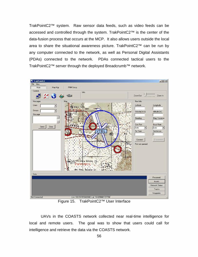
56
TrakPointC2™ system. Raw sensor data feeds, such as video feeds can be
accessed and controlled through the system. TrakPointC2™ is the center of the
data-fusion process that occurs at the MCP. It also allows users outside the local
area to share the situational awareness picture. TrakPointC2™ can be run by
any computer connected to the network, as well as Personal Digital Assistants
(PDAs) connected to the network. PDAs connected tactical users to the
TrakPointC2™ server through the deployed Breadcrumb™ network.
Figure 15. TrakPointC2™ User Interface
UAVs in the COASTS network collected near real-time intelligence for
local and remote users. The goal was to show that users could call for
intelligence and retrieve the data via the COASTS network.
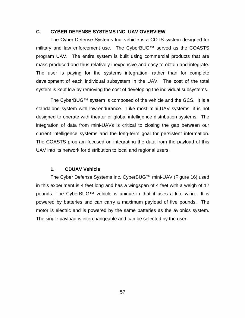
57
C. CYBER DEFENSE SYSTEMS INC. UAV OVERVIEW The Cyber Defense Systems Inc. vehicle is a COTS system designed for
military and law enforcement use. The CyberBUG™ served as the COASTS
program UAV. The entire system is built using commercial products that are
mass-produced and thus relatively inexpensive and easy to obtain and integrate.
The user is paying for the systems integration, rather than for complete
development of each individual subsystem in the UAV. The cost of the total
system is kept low by removing the cost of developing the individual subsystems.
The CyberBUG™ system is composed of the vehicle and the GCS. It is a
standalone system with low-endurance. Like most mini-UAV systems, it is not
designed to operate with theater or global intelligence distribution systems. The
integration of data from mini-UAVs is critical to closing the gap between our
current intelligence systems and the long-term goal for persistent information.
The COASTS program focused on integrating the data from the payload of this
UAV into its network for distribution to local and regional users.
1. CDUAV Vehicle The Cyber Defense Systems Inc. CyberBUG™ mini-UAV (Figure 16) used
in this experiment is 4 feet long and has a wingspan of 4 feet with a weigh of 12
pounds. The CyberBUG™ vehicle is unique in that it uses a kite wing. It is
powered by batteries and can carry a maximum payload of five pounds. The
motor is electric and is powered by the same batteries as the avionics system.
The single payload is interchangeable and can be selected by the user.
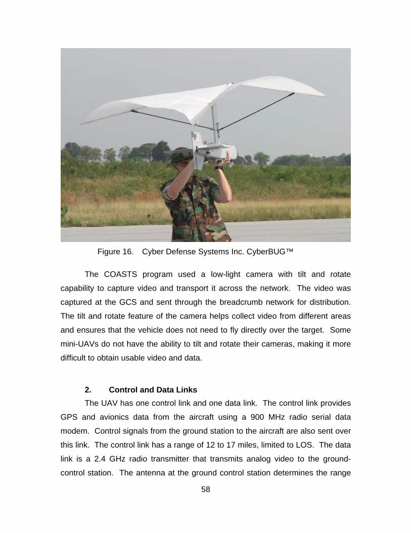
58
Figure 16. Cyber Defense Systems Inc. CyberBUG™
The COASTS program used a low-light camera with tilt and rotate
capability to capture video and transport it across the network. The video was
captured at the GCS and sent through the breadcrumb network for distribution.
The tilt and rotate feature of the camera helps collect video from different areas
and ensures that the vehicle does not need to fly directly over the target. Some
mini-UAVs do not have the ability to tilt and rotate their cameras, making it more
difficult to obtain usable video and data.
2. Control and Data Links The UAV has one control link and one data link. The control link provides
GPS and avionics data from the aircraft using a 900 MHz radio serial data
modem. Control signals from the ground station to the aircraft are also sent over
this link. The control link has a range of 12 to 17 miles, limited to LOS. The data
link is a 2.4 GHz radio transmitter that transmits analog video to the ground-
control station. The antenna at the ground control station determines the range
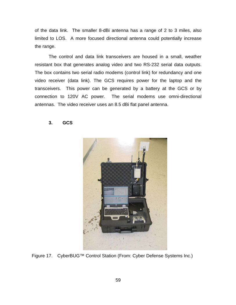
59
of the data link. The smaller 8-dBi antenna has a range of 2 to 3 miles, also
limited to LOS. A more focused directional antenna could potentially increase
the range.
The control and data link transceivers are housed in a small, weather
resistant box that generates analog video and two RS-232 serial data outputs.
The box contains two serial radio modems (control link) for redundancy and one
video receiver (data link). The GCS requires power for the laptop and the
transceivers. This power can be generated by a battery at the GCS or by
connection to 120V AC power. The serial modems use omni-directional
antennas. The video receiver uses an 8.5 dBi flat panel antenna.
3. GCS
Figure 17. CyberBUG™ Control Station (From: Cyber Defense Systems Inc.)
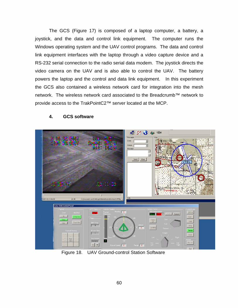
60
The GCS (Figure 17) is composed of a laptop computer, a battery, a
joystick, and the data and control link equipment. The computer runs the
Windows operating system and the UAV control programs. The data and control
link equipment interfaces with the laptop through a video capture device and a
RS-232 serial connection to the radio serial data modem. The joystick directs the
video camera on the UAV and is also able to control the UAV. The battery
powers the laptop and the control and data link equipment. In this experiment
the GCS also contained a wireless network card for integration into the mesh
network. The wireless network card associated to the Breadcrumb™ network to
provide access to the TrakPointC2™ server located at the MCP.
4. GCS software
Figure 18. UAV Ground-control Station Software

61
The GCS computer runs four programs to operate the UAV.
TrakPointC2™, VideoLAN Client (VLC), the UAV control software, and Microsoft
NetMeeting are all hosted on the computer.
TrakPointC2™ was used for chat functionality, displaying the location of
the UAV on a map and distributing GPS coordinates to other users on the
network. VLC, a cross-platform media player, was used to display the video
collected from the UAV through the capture device. Microsoft NetMeeting was
run to allow users to receive the UAV video.
The ground-control station transmits National Imagery and Mapping
Agency (NIMA) GPS data that can map the position of the UAV on a mapping
product, such as TrakPointC2™ or FalconView™. TrakPointC2™ collected the
GPS information from the laptops com1 serial port and displayed this location on
the map. TrakPointC2™ was configured as a client to the TrakPointC2™ server
running at the MCP. The chat function was used to coordinate UAV operations
over the network.
The UAV control software (Figure 18) allows control of the UAV in either a
manual or an autonomous control mode. The control software manipulates the
camera in addition to the UAV system. Detailed control inputs include heading,
altitude, and camera orientation information. The motor speed and control
surface orientation are depicted as well.
The autonomous mode utilizes GPS and waypoints which can be set for
the aircraft to follow. There is a return-to-base function that provides for the
aircraft to return to the ground-control station with the loss of the control link.
There is also a function that flies the aircraft to wherever the camera is pointed.
If an object of interest is found, the aircraft can be told to circle over that
particular area. In the event the operator wishes to override the autonomous
operation, there is a function to allow manual control of the aircraft using either
the joystick or buttons in the control software.
VLC is an open-source program that can be obtained from
http://www.videolan.org/vlc/. This program is used to display video from the UAV

62
as well as to record the data for later review. This program is also capable of
streaming video across a network; however, it was not used to perform this
function during the COASTS demonstration. VLC integration TrakPointC2™ was
not fully developed in time for the COASTS demonstration. Microsoft NetMeeting
was used to stream video as a substitute for VLC.
D. UAVS IN THE COASTS PROGRAM The mini-UAV in the COASTS program was intended to research general
parameters in which COTS mini-UAVS could be used in the field and integrated
into a surveillance network. The primary goal of this demonstration was to
integrate video from the UAV into the COASTS network. The following goals
were set from which to evaluate the UAV.
• Effectively setup computer to digitize data from UAV RF link
• Transmit digitized video feed onto network through 802.11 Breadcrumb™ network
• Effectively view the transmitted data with a high degree of resolution and reliability at the MCP
• Effectively provide GPS coordinates of the UAV and UAV control station to the MCP
• Test and maintain connectivity to the CyberBUG™ UAV
• Explore and capture techniques, tactics and procedures, which can be leveraged in further testing
• Explore range limitations of the RF link
Not all of the goals could be met. The UAV was flown only three times. In
each of these flights the UAV was difficult to control for reasons described below
which resulted in uncontrolled landings. The third flight left the UAV inoperable
after it crashed. The factors involved in these crashes yielded valuable data to
leverage in future tests. RF link limitations, connectivity, and certain techniques,
tactics and procedures could not be captured due to the UAV mishap. The video
was captured and transmitted through the network, but the video was not seen
with a high degree of resolution or a fast frame-rate.

63
The UAV was pushed to its operational limits in Thailand. During these
flights the conditions were above the design parameters for the UAV, which
resulted in problems with each of the three flights. The high heat and humidity
produced a situation in which the altitude (98 feet) of the airfield had a density
altitude of 3,700 feet. The effect was as though the aircraft was flying at 3,700 ft
higher than the actual altitude. The high winds also created control issues. The
aircraft could not be effectively flown into the wind. The high winds, 15 to 20
knots, when combined with the effects of the high temperature and humidity,
pushed the aircraft beyond its operational envelope. This is an important
limitation that must be corrected for future operations in areas of high heat and
humidity.
E. CYBER DEFENSE SYSTEMS INCUAV VIDEO INTEGRATION The untimely mishap of the UAV meant that the video integration became
the most important part of the UAV operations. Analog video was received from
the output of the data link. This video was then integrated into the network using
a Dazzle™ video capture card from Pinnacle Systems (Figure 19). This video-
capture device digitized the analog signal sent by the data link. It works over
Universal Serial Bus (USB) and supplies live video digitization from the source.
Figure 19. Dazzle Video-capture Device

64
VLC received the digitized video from the source and displayed it on the
laptop screen while the video feed was recorded. Microsoft NetMeeting used the
same video-capture device to obtain the video for distribution over the network.
Figure 20. Microsoft NetMeeting
Microsoft NetMeeting (Figure 20) was configured to distribute video to any
user that connected to it. Clients wishing to receive UAV video connected to the
UAV laptop using NetMeeting. The UAV laptop was configured to automatically
accept any attempts to connect to it through NetMeeting.
The connection through NetMeeting was slow and required considerable
bandwidth. Frame-rates of 3 to 5 frames per second were typical during average
usage of the COASTS network. Frame-rates dropped below 1 frame per second
when multiple users were connected through NetMeeting. Video resolution was
low and not clear.
65
F. SUMMARY The first iteration of COASTS offered an opportunity to develop
relationships with COTS UAV vendors that should prove beneficial in the future.
The mishap involving the UAV reduced the number of goals that could be
attained; however, the three flights provided good data on the effects of wind and
high density altitude on mini-UAVs. The density altitude of 3,700 feet coupled
with the high winds forced the UAV to operate outside of its envelope. This is an
issue of mini-UAV systems that warrants future research.
The wind limited the direction of flight of the UAV and pushed it off course.
The UAV could not be controlled without consideration of the winds. Awkward
patterns had to be flown to reduce the effects of wind while trying to survey a
target. In some circumstances, the strong wind prevented the UAV from even
reaching the target area, as it could not maintain its heading into the wind.
The dissemination of video from the GCS leaves much to be desired. The
transmitted video required considerable bandwidth that degraded the other video
feeds on the network. Low frame-rates limited the usefulness of the video and
made it hard to concentrate on analyzing the feed. Higher frame rates and better
quality video are needed to support fast decision-making. Data compression
technologies need to be explored to reduce bandwidth requirements and provide
high quality video.
This chapter was a direct product of the experiences from this exercise.
The next iteration of COASTS will include a greater number of UAVs of varying
sizes, technology, and capability.

66
THIS PAGE INTENTIONALLY LEFT BLANK
67
V. COASTS CASE STUDY
A. INTRODUCTION Up to this point, each node was able to perform individually; this scenario
was developed to showcase the functionality of the COASTS system as a whole.
In cooperation with the Thai government, the NPS COASTS team
developed a scenario to demonstrate the utility of the COASTS network. A
number of trial runs were performed on 16 May 2005 in preparation for the 17
May demonstration. The scenario was executed at the Wing Two airfield in Lop
Buri, Thailand.
The loss of the mini-UAV left the COASTS program without a UAV
capability for demonstration; therefore only intended use of the mini-UAV in this
scenario can be presented.
B. SCENARIO
1. General Information The scenario developed by the COASTS team focused on utilizing the
network during a counter-drug operation. In the scenario an intelligence tip was
received that warranted the deployment of the Coalition Operating Area
Surveillance and Targeting System to support the surveillance and apprehension
of drug traffickers. The tip stated the time and location of a drug transfer from a
storage facility to a van for transportation and distribution. It also included the
make and model of the van being used to pick-up and transfer the drugs and a
description of the drug traffickers.
A team of Thai commandos and a member of the NPS staff composed the
interdiction team. An NPS student and a contract van driver played the role of
the drug traffickers. NPS students and faculty manned the MCP and provided
Command and Control of the various sensors and units in the field.
68
The scenario was run at 1030 local time on 17 May under clear skies.
The winds were blowing at 5 knots from the southeast. The temperature was
around 90°F with a density altitude of about 3,500 feet.
2. Network Description The network consisted of cameras, sensors, and wireless data relays,
deployed specifically to support the surveillance and apprehension of the drug
traffickers. Figure 21 depicts the network set-up and movement of the drug
traffickers. The network centered around the MCP which was located in the
control tower of the Wing Two airfield.
One function of the MCP was to host the TrakPointC2™ server for local
and remote access to real-time Situational Awareness (SA). Remote users
connected to the server over the E-1 and T-1 links described in the previous
chapter. The Breadcrumbs™ provided the tactical connection to the MCP. The
UAV node, the interdiction team, all of the cameras, and the sensor grid were
connected to the network through the Breadcrumbs™.
The interdiction team was equipped with a Tacticomp™ PDA device that
connected to the network and allowed access to the TrakPoint™ server. The
client running on this PDA passed GPS data to the server and acted as a
tracking device for the interdiction team.
Multiple radio frequencies were utilized during this demonstration. The
UAV used a 900 MHz control link and a 2.4 GHz data link. The Breadcrumbs™
operated at 2.4 GHz. The Redline Communications gear for linking remote users
to the MCP operated at 5.4 and 5.8 GHz

69
Figure 21. COASTS Scenario

70
3. Detailed Scenario Description Figure 21 depicts the movement of the drug traffickers through the
scenario. At point 1 the van crosses the sensor grid, which registers through the
TrakPointC2™ software. This alerts the surveillance team in the MCP via the
TrakPointC2™ interface to the presence of a vehicle. The team then accesses
the video feed from camera A to determine the make and model of the vehicle.
The surveillance team determines that this is a vehicle of interest and begins
tracking the vehicle utilizing camera A and camera B. Once the surveillance team
verifies that this is the reported suspect vehicle, it notifies the interdiction team to
prepare to arrest the drug traffickers. The interdiction team communicates with
the MCP via the chat function of TrakPointC2™. The COASTS network
continues to use cameras C and D to track the van to the drug exchange
location.
Once the van reaches the drug transfer location (point 3) camera D is
used to monitor the drug transfer and confirm the identity of the drug traffickers.
The members of the interdiction team access live video of the van and the drug
traffickers through the Tacticomp to assist in apprehension. Video of the transfer
allows confirmation of the drug transfer and provides justification for the
interdiction team to arrest both the suppliers and the drug traffickers.
Once the van leaves point 3 with the drugs the surveillance team at the
MCP notifies the interdiction team and instructs them to prepare to apprehend
the van. The MCP continues to monitor the van as it travels to point 4. The MCP
is able to track the interdiction team using the GPS tracking functionality of
TrakPointC2™. Before the van reaches point 4 the MCP notifies the interdiction
team to apprehend the van and arrest the suspects using chat.
The MCP monitors the drug traffickers as they travel through the
surveillance area. It also provides all of the monitored feeds to remote users.
Specific goals were set for the scenario and are described below.

71
4. Measures of Effectiveness/ Measures of Performance The COASTS team developed a number of Measures of Effectiveness
(MOE) from which to gauge the success of the operation. MOEs are based upon
qualitative attributes. Conversely, Measures of Performance (MOP) are based
upon meeting quantitative objectives. The "Benchmarks for success in COASTS
were not based upon numerical data, they were based upon success or failure of
the scenario" (Clement). This first iteration of the COASTS project focused on
meeting MOEs and collecting data to facilitate creating MOEs and MOPs for the
next iteration. The first iteration of the COASTS project was more concerned with
what can be done, rather than how well we can do it. Results from this iteration
of the COASTS project will feed future development of MOEs and MOPs.
The MOEs for this scenario were:
• Does the sensor event register in TrakPointC2™?
• Can the video from the cameras be viewed at the MCP via the breadcrumb network?
• Can the cameras be controlled at the MCP via the breadcrumb network?
• Did the video feed facilitate identification of the van (e.g. make, model, color, license plate)?
• Did the video feed provide positive identification of the drug traffickers?
• Was continuous surveillance of the van and drug traffickers maintained?
• Were users able to use chat through TrakPointC2™?
• Was the interdiction team able to be tracked through TrakPointC2™?
• Was the interdiction team able to be tasked through TrakPointC2™?
• Was the interdiction team able to access video on the Tacticomp in order to identify the suspects?
72
C. RESULTS
1. Measures of Effectiveness a. Sensor Event The sensor events were not able to register in TrakPointC2™. This
was due to a problem with the integration of the Crossbow sensors into the
TrakPointC2™ software and limitations of the sensors employed. The
development and integration process took longer than expected and the sensor
grid was not directly integrated into the situational awareness software. The
sensors purchased provided a limited ability to detect vehicles. A human had to
take the place of the sensor grid and report the arrival of the van to the MCP
using a cellular phone.
b. Camera Viewing The operation and viewing of the cameras through the breadcrumb
network worked well. The cameras could be controlled from the local area
network for the demonstration.
c. ID Van The video feed facilitated the identification of the van. The cameras
provided enough resolution and control to obtain the make, model, color, and
license plate of the van. If this had been a scenario involving multiple vehicles it
would have been easy to track this vehicle utilizing this information.
d. ID Traffickers The video feed facilitated positive identification of the drug
traffickers. Video of the drug transfer allowed the identification of the drug
traffickers through recognition and comparison.
e. Continuous Surveillance Continuous surveillance of the van was not possible due to
obstructions to the camera view. This gap in coverage only lasted approximately
10 seconds. If the UAV had been flying it might have been able to fill this
coverage gap.
73
f. TrackPointC2™ Chat Users were able to chat using TrakPointC2™. This provided an
excellent resource for C2 of deployed units from the MCP to the field. The
Tacticomp user in the field had a hard time sending messages to the MCP due to
problems with the interface design. The Tacticomp user was required to use a
stylus to type in letters one at a time in order to write a message. This limited his
ability to respond to queries and introduced delay when the interdiction team
needed to make statements or call for support.
g. TrackPointC2™ Tracking The interdiction team could be tracked through TrakPointC2™.
The Tacticomp collected GPS coordinates and forwarded them to the server at
the MCP. This allowed all users running TrakPointC2™ to track the interdiction
team.
h. TrackPointC2™ Tasking The interdiction team was effectively tasked through
TrakPointC2™. The messages to the interdiction team were clear and full of
detail. The interdiction team was tasked to stop and arrest the drug traffickers in
the van through the network.
j. Tacticomp Video Access The interdiction team was not able to access the video utilizing the
Tacticomp. While technically feasible, the software to access and play the video
was not installed. The Tacticomp required a Java runtime installed on the PDA,
however it was not possible to install this software in the field.
2. Observations The use of the COASTS network provided support to the interdiction team
in the field. Utilizing the surveillance functions of the network, the MCP was able
to positively identify the vehicle and collect evidence of the drug transfer without
alerting the drug traffickers. By starting surveillance early, the MCP was able to
positively identify the van and passengers, providing the interdiction team with
74
SA and advanced notice so that it could concentrate on intercepting and
detaining the target. The COASTS network removed the responsibility of
identifying the target from the interdiction team.
While not all of the MOEs were met, the interdiction team was still able to
utilize the network and the expertise of the people in the MCP to reduce the
burden of identification. By distributing the identification phase through the
network all members of the interdiction team could focus on stopping and
capturing the drug traffickers rather than using team members to identify the drug
traffickers. The COASTS network reduced the manpower that needed to be
distributed by substituting cameras and equipment for personnel.
3. Limitations The COASTS network required a long time to deploy. Once units were
deployed to their locations the network setup was fast; however, the unknown
limitations with the wireless network forced the team to adjust the density of
breadcrumbs in the operational area, which cost the team valuable time.
The number of people required to set-up the network also offset the
decreased number of people needed during the entire operation. While the
COASTS network decreased the required manpower onsite to successfully
complete the scenarios, the manpower needed to fix network issues offset this.
The bandwidth available on the reach-back network could not support the
large number of users that wanted to access the video feeds. An attempt was
made to implement multicasting of the video, but the Breadcrumbs™ did not
support this bandwidth saving technology. The number of frames-per-second
decreased as more users simultaneously accessed the video feeds. This issue
must be dealt with, as it is difficult to use choppy and fuzzy video to make
identifications. Bandwidth issues were minimized in the demonstration by limiting
the number of people requesting video feeds from cameras.
The sensors need to be improved and fully integrated with TrakPointC2™.
The sensors were not able to detect the van as it passed through the sensor grid.

75
This is a major limitation as the network depends on the sensor grid as a first-
alert mechanism to potential activity.
The chat function on the Tacticomps was hard to use and required a great
deal of time for the user to enter simple messages. Individual characters had to
be entered into the unit with the stylus. In order to report the status of the
interdiction unit it was necessary for the NPS faculty member on the interdiction
team to be solely focused on operating the Tacticomp.
There was no testing of distributing SA to remote users in this
demonstration. While earlier tests showed that it was possible to stream video to
remote users in Bangkok, this was not done during the scenario.
The density of cameras was greater than it would be in an actual
deployment. In the demonstration the cameras provided nearly full coverage;
however, an actual deployment would require cameras, sensors, and nodes to
be deployed over a larger area. The same amount of resources deployed over a
larger area could reduce the coverage of the vehicle, resulting in windows in
which the vehicle was not being tracked.
The cameras in this demonstration were static. The route and intentions
of the drug traffickers were known a priori; this allowed the network to be setup
easily, but if the tip was incorrect it might result watching the wrong area.
4. Follow-on Suggestions The COASTS network just completed its first iteration. There are lessons
to be captured and taken into consideration for future evolutions. Future
demonstrations should focus on MOPs as well as MOEs. Robust data collection
procedures will be needed to support MOPs. A detailed Test and Evaluation
Master Plan (TEMP) should be developed to support collection and analysis of
results.
The COASTS program should focus on creating a more rapidly deployable
network that does not need detailed configuration during setup. Future
76
scenarios, based on real-world requirements, must be developed before the
operation so that proper equipment can be integrated into the network. The
scalability of the COASTS network should be explored in detail. Increasing the
number of integrated components in the system will allow judicious selection of
components to meet a variety of missions, rather than relying on a limited
selection of components that will only fulfill the mission requirements partially.
It is evident from the results of the first iteration that the COASTS network
must be able to adapt to the situation. Detailed information on adversary
movements is not usually available thus, it is important to be able to adapt to
their movements. Stationary cameras have limited a field-of-view due to
obstructions, their placement, and the design of the cameras. Mobile units that
can rapidly adapt to cover areas out of view of the stationary sensors should be
integrated into the network. The mini-UAV was supposed to provide adaptable
coverage, however the crash precluded its use in this scenario. The next section
presents the intended use of the mini-UAV.
D. UAV USE The UAV was anticipated to provide continuous surveillance of the van
and drug traffickers throughout the scenario. This continuous surveillance could
not be provided by stationary units due to obstructions of their views and
limitations of the cameras. Specific MOEs were developed for the mini-UAV in
the scenario, but it was not possible to test these MOEs because the UAV was
not capable of being employed in the demonstration. The mini-UAV MOEs are
presented below for general analysis and consideration. The MOEs for the UAV
were as follows:
• Could the UAV be tasked through TrakPointC2™?
• Was the UAV able to take-off?
• Was the UAV able to climb and maintain its altitude?
77
• Was the UAV able to be effectively operated to maintain
surveillance of the target vehicle?
• Was the vehicle able to land?
1. Intended Use Planning and setup of the network indicated that the best location for the
UAV was in the field adjacent to the road along which the target would be
traveling. The open area of the field permitted the UAV plenty of room for take-
off and landing.
The UAV was to be used for continuous surveillance of the van and drug
traffickers during the demonstration. When the sensor grid detected the
presence of the van (point 1) the UAV was to be launched by a command from
the MCP through the TrakPointC2™ chat function.
After launch the UAV was to climb to an altitude of 800 feet while in a
downwind turn. The requirement was to track the target as soon as possible
while transiting to the drug exchange location (point 3). At the drug exchange
location the UAV was to circle the area and relay real-time video through the
COASTS network.
After capturing the transfer of the drugs the UAV was to descend and land
in the field from which it launched.
2. Observations Even though the UAV did not fly, the order to take-off was sent through
TrakPointC2™ and received at the GCS. Unfortunately several of the MOPs
were not met due to the inoperability of the UAV.
Planning was a big factor in employment of the UAV. Launch of the UAV
could not be immediately accomplished without a great deal of forethought and
planning. Mission planning and the UAV preflight checks had to be completed
before the arrival of the target. Factors such as wind direction, location of the
78
unit in relation to obstructions, and the intended time aloft were considered. No
other aerial assets were to be employed during the scenario, so coordination was
not a large issue. The demonstration took place around an airport and all air
operations were coordinated with the control tower. In the even that a plane did
stray into the area or attempt to land the UAV was to be immediately crashed into
the ground upon notification from the control tower.
Winds were minimal during the demonstration, so control of the UAV
would not have been a problem. The high temperature and humidity might have
been a problem for the UAV if combined with the wind, but a clear determination
of the effects of just the high temperature and humidity cannot be made without
more testing.
A map of the area was beneficial to plan the route and use of the UAV,
however it was possible to deviate from this plan if the target decided to deviate
from the intelligence provided. The stationary units in the demonstration were
not able to simultaneously adapt to large changes in location of the drug
exchange, however the UAV would have been able to follow and track the van
through gaps in coverage of the stationary cameras.
Endurance would have been a large factor during the operation. The low-
endurance of the mini-UAV (45 minutes) limited the time aloft. The UAV could
not loiter in the area until the target arrived because it might not have had
enough battery power to maintain surveillance of the target throughout the
operation. The launch of the UAV upon arrival of the van at the sensor grid
allowed the UAV to spend all of its available time tracking and monitoring the
target.
Landing was another area that could have been a problem for the UAV.
During the descent the UAV would have been required to avoid numerous trees
around the field. It would have been important to line the UAV up with the field
and start the descent at the perfect time to make sure the UAV did not overshoot
or undershoot the field.
79
Maintaining LOS during the entire operation would have been important.
If LOS was lost due to the UAV flying behind a building then the control link
would have been lost and the UAV might have crashed. LOS would also have
been a consideration during the landing phase due to the potential interference of
trees surrounding the landing area.
3. Limitations The limitations of employment of the UAV were not completely captured
due to the lack of a flight during the demonstration. The previously mentioned
factors would likely have played a role. Environmental factors such as
temperature, humidity, and wind would have presented the largest obstacles to
employment of the UAV.
E. SUMMARY Though the UAV did not fly in the demonstration scenario, extrapolations
could be made to illustrate the utility of a mobile surveillance platform. The entire
COASTS network focuses on the ability of the network to be rapidly deployed to
collect intelligence and support operations. This network should not be viewed
as a persistent entity. It should be viewed as a temporary system designed to
support individual operations.
The use of a UAV in the demonstration could have increased the
adaptability of the network by allowing the UAV to follow the van and drug
traffickers if they had deviated from their plan for the drug transfer. UAVs also
have the potential to provide coverage in situations where intelligence is
inaccurate.

80
THIS PAGE INTENTIONALLY LEFT BLANK

81
VI. CONCLUSIONS
A. CONCLUSIONS This thesis has considered the use of mini-UAVs at the tactical operations
level. Currently, squad, platoon, and company units of maneuver have difficulty
obtaining intelligence from higher-level C4I systems. This problem is
compounded when these units are on the move. Systems to connect and
interact with intelligence databases do not allow these tactical units the mobility
they require to wage war. These mobile interfaces are usually located with
battalion-sized units and larger.
This thesis has explored the use of mini-UAVs as an organic asset for
intelligence gathering. Instead of requiring connection to C4I systems, these
mini-UAV equipped units can determine their own requirements for intelligence
collection. The implications of mini-UAVs at the tactical operations level were
explored through field experiments and literature review.
Mini-UAVs, despite their small size, must still have a plan for operation.
Environmental considerations in the tactical operations area must be considered
before employment. The short loiter times limit the ability for one unit to provide
persistent surveillance. Mini-UAVs are best employed to accomplish specific
objectives such as clearing an area, or searching for a target in a known location.
Each mission must be planned in detail to gain the most utility. Mini-UAVs
cannot loiter in an area to provide immediate surveillance like high-endurance
systems.
The level of technology incorporated into these units is not currently to the
point that they can be expected to operate autonomously. Human interface is
required during launch and operation of the UAV. Multiple personnel are
required to launch the UAV, and these units are not capable of being launched in
all conditions. At the tactical level this means that one or more members of the
squad, platoon, or company will not be available for direct combat. This creates
a deficiency of direct combat power for small units, as some of the members
82
must operate the UAV; however, the information garnered through these mini-
UAVs may allow the unit to be employed more efficiently and result in more
effective combat power.
While mini-UAVs are capable of many different missions, the most
effective missions involve the use of these units as an "eye in the sky." These
missions are used to quickly provide a picture of what is "around-the-corner" or
"over-the-hill." Missions that require detailed analysis of imagery or data from the
payload require specially trained operators experienced with the tactics of
employing these units. Typical ground units do not require the need for
specialized payloads that would require expert analysis. Tactical units are mostly
concerned with obtaining real-time intelligence to support ongoing operations.
The security of mini-UAV systems is an additional concern. The tendency
for them to crash is high. While there is little data on the reliability of mini-UAVs,
it is generally thought that they fail more often than larger UAV systems. This is
due in part to the design of the components in these systems, but also due to the
lack of redundant systems. Since COTS components are mainly used, if a UAV
is recovered by an enemy it can easily be backwards engineered to allow the
enemy to collect data from friendly units and possibly even control the UAV.
The future will require mini-UAVs to be more closely integrated with other
intelligence systems. COTS mini-UAV systems are not designed for
interoperability with current or planned intelligence systems. Stovepipe
development cuts down the costs, but it also inhibits higher-level commanders
from accessing the local intelligence data collected by mini-UAVs. The
integration of mini-UAVs into intelligence networks will bring the military closer to
a concept of persistent intelligence. The distribution of mini-UAVs will provide
redundancy and increased detail of tactical operations.
The COASTS program illustrated the utility of providing a tactical
integrated intelligence collection system. The ability to view what tactical units
are seeing allows commanders to better consider the tactical maneuvers that can
have strategic implications. While this is no substitute for ground truth, it
83
increases the accuracy with which strategic commanders can understand the
tactical picture.
B. RECOMMENDATIONS Based upon the work of this thesis there are several recommendations
pertaining to mini-UAVs.
The autonomy of mini-UAVs must be increased so that users can task and
forget about these units until they report back to the user with the requested
information. This autonomy would remove most planning, launch, transit, and
recovery considerations from the user. The reduction of human input would
allow the user to concentrate on other tasks and utilize the data from the UAV
without having to devote personnel to operating the UAV.
UAVs need to be developed that are available for use in adverse weather
conditions. UAVs should be developed that can fly in conditions of high heat and
humidity combined with moderate wind conditions. These units should use
weather to their advantage and should provide a stable platform for any sensor
or camera.
Sensors and cameras need to be developed that provide high-resolution
images and data. In addition, more advanced payloads should be produced, but
these should only be employed by appropriately trained personnel.
The security of systems needs to be increased so that adversaries do not
exploit friendly assets. Data and control links should be encrypted to prevent
adversaries from obtaining our data. While it might not be possible to destroy
mini-UAVs if they crash, it is important to minimize crashes that would place the
technology into the hands of an adversary. This will become more important as
UAVs become more capable. SIGINT mini-UAV systems will require robust
security so that the enemy cannot determine our capabilities or examine what we
are collecting.

84
The DOD should push for interoperable systems that can rapidly integrate
into current and future intelligence and data dissemination systems. Users must
be able to share information. Integration of mini-UAVs into intelligence systems
has the potential to broaden the perspective of higher-level commanders.
C. FOLLOW-ON WORK Mini-UAVs are developmental. While there are a number of systems
available, there is room for future improvements in design and operation of these
systems. Follow-on work should consider the limitations and gaps in knowledge
presented by this thesis. The following is a list of follow-on work:
• A study of the weather limitations of various systems
• Development of tactics for mini-UAVs
• Collection and analysis of data on mini-UAV reliability and operational availability
• Continued development of protocols and mechanisms to integrate mini-UAV sensor data into intelligence networks
• Development of standard procedures for planning and integrating mini-UAVs into the ATO rapidly when necessary
• A study on the use of mini-UAVs for targeting and battle damage assessment
• Development of standards for when it is permissible to use mini-UAVs without ATO coordination
The author would suggest the development of an NPS sponsored UAV for
the COASTS project. This would allow greater control over the internal
components and the ability to integrate technologies from other venders without
major legal issues.
85
APPENDIX A
86

87
88

89
90

91

92

93

94

95
96
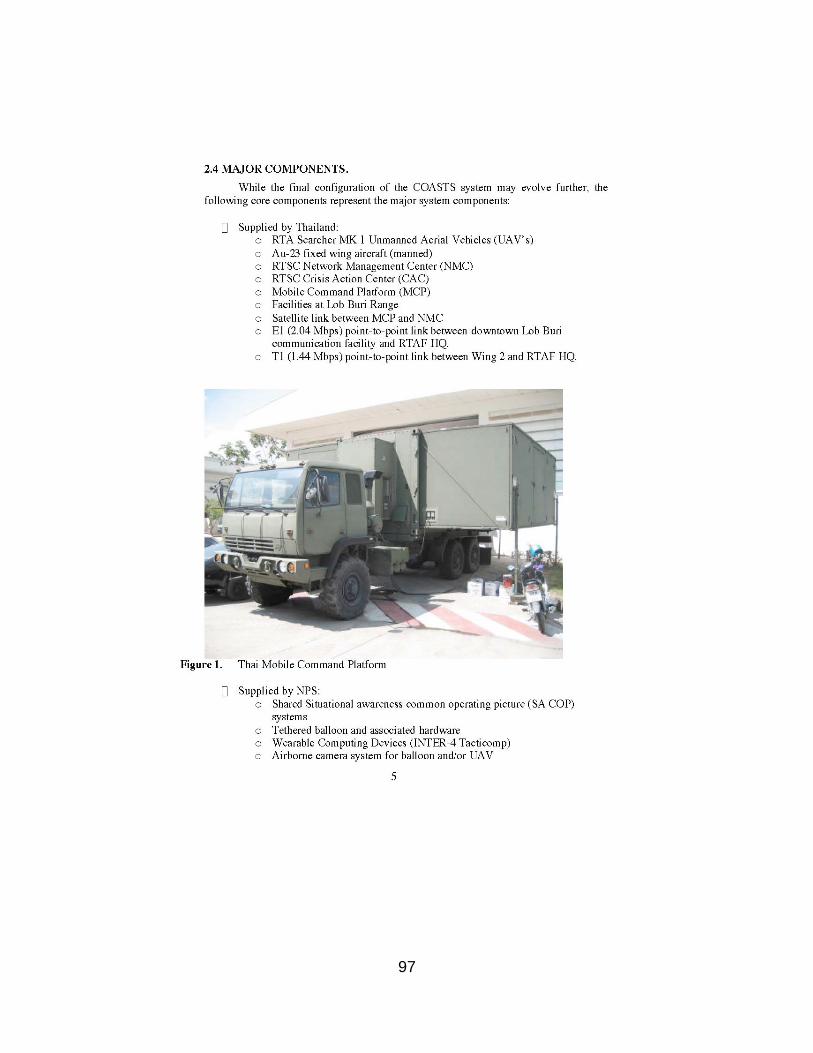
97

98
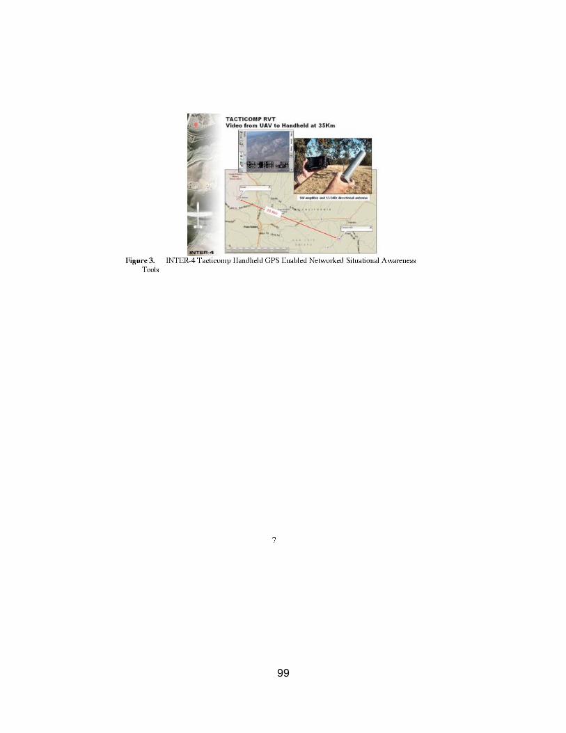
99

100
101
102
103
104
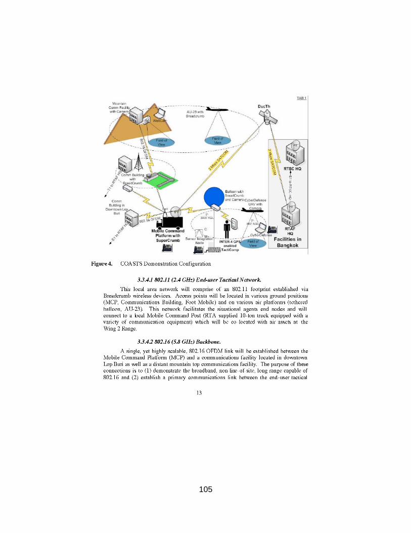
105

106

107

108
109
110

111
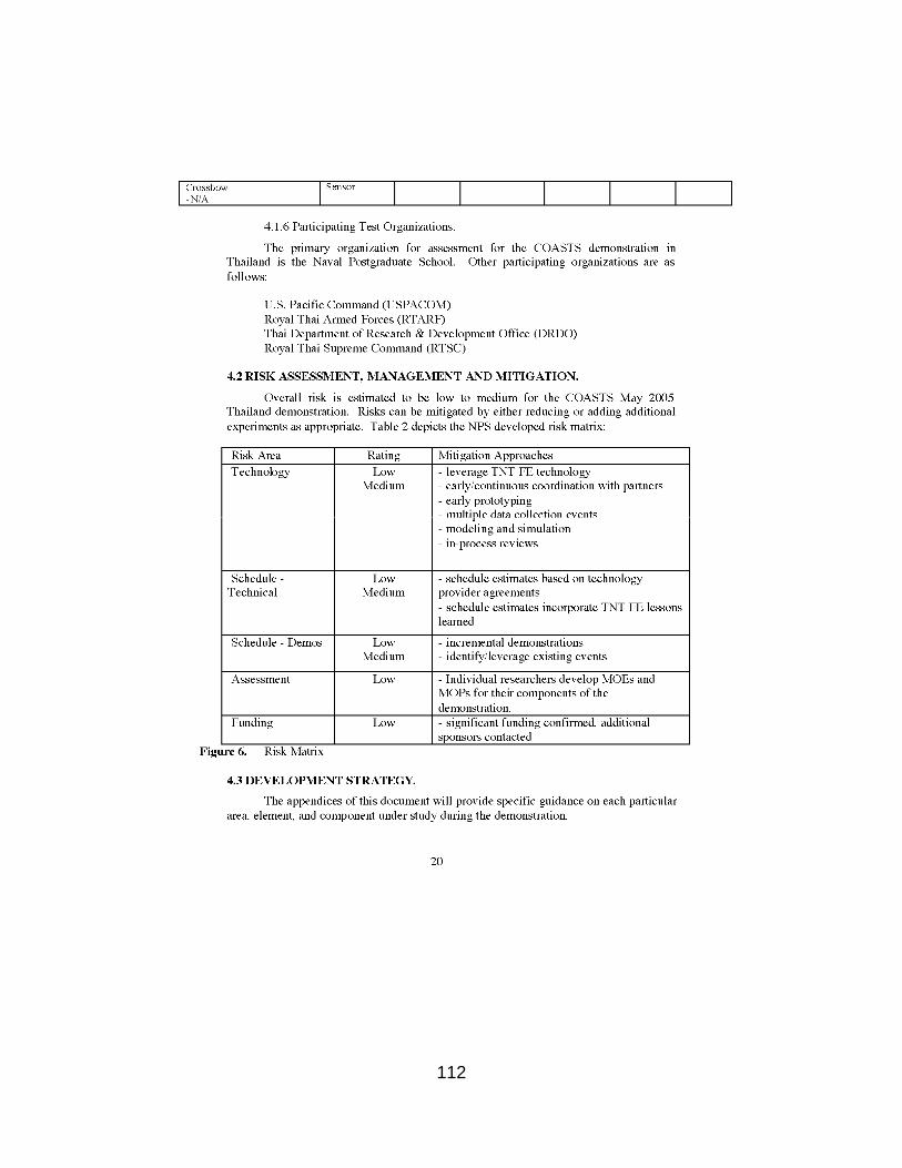
112

113

114

115
116
117

118

119

120
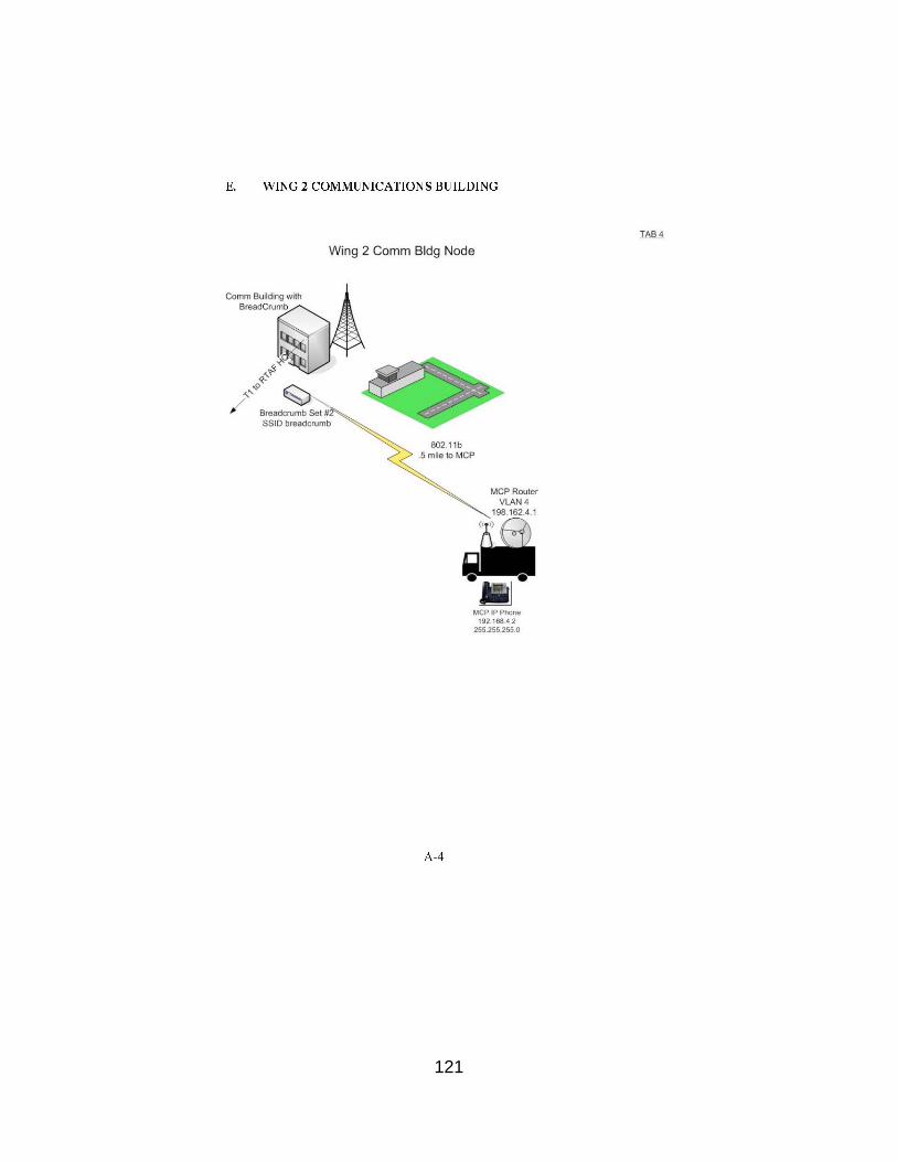
121

122
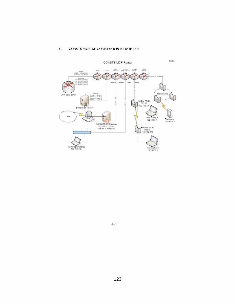
123
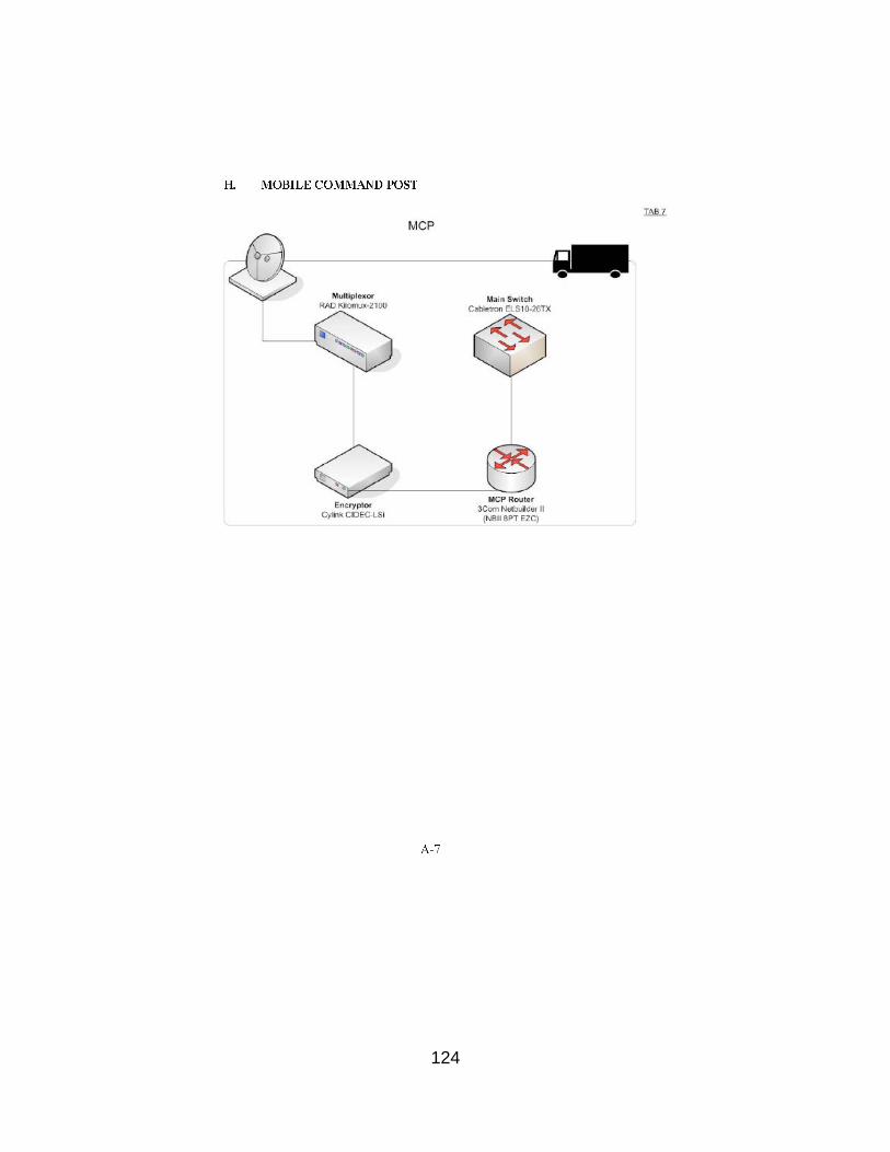
124

125

126
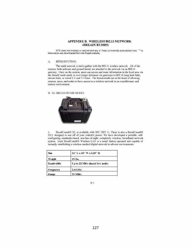
127

128

129
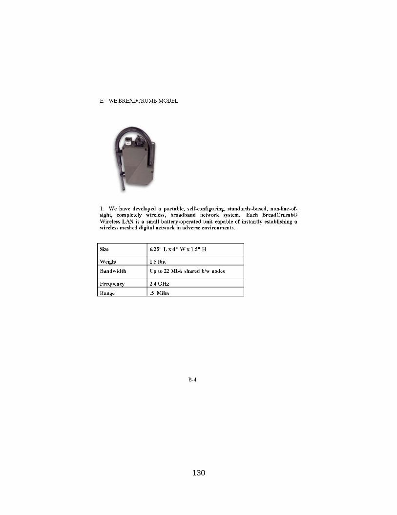
130

131
132

133

134
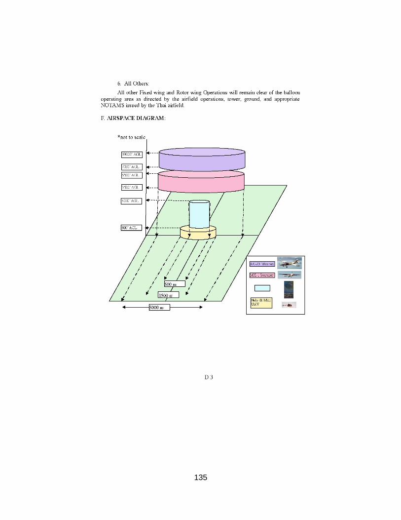
135

136
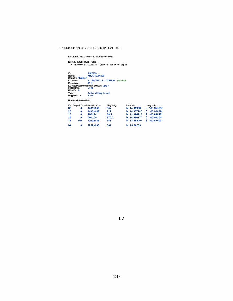
137
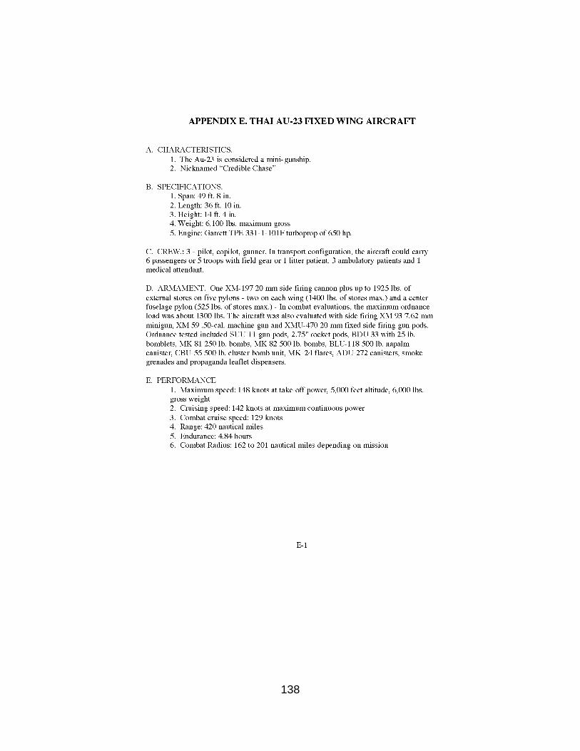
138
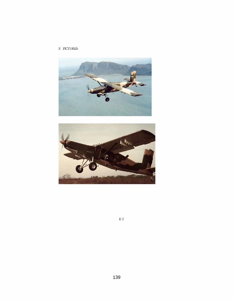
139
140

141
142

143
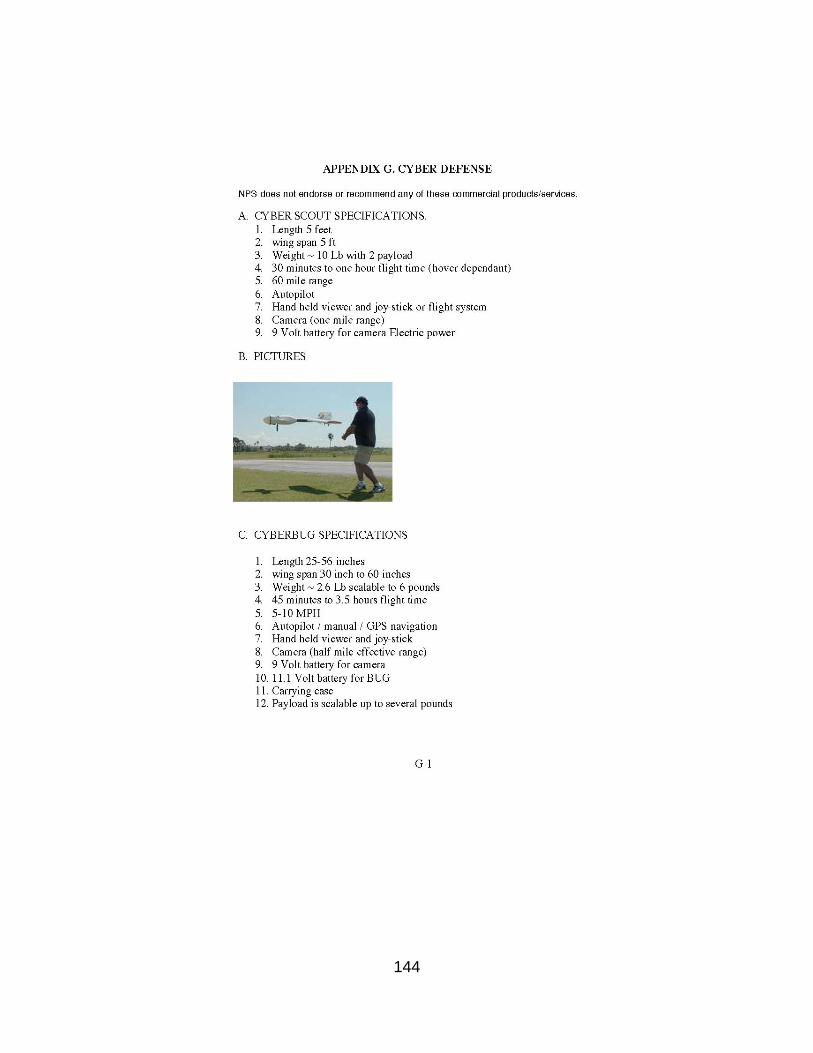
144

145
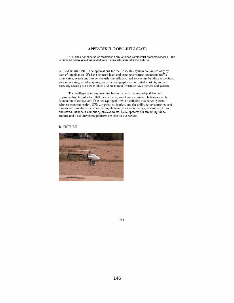
146
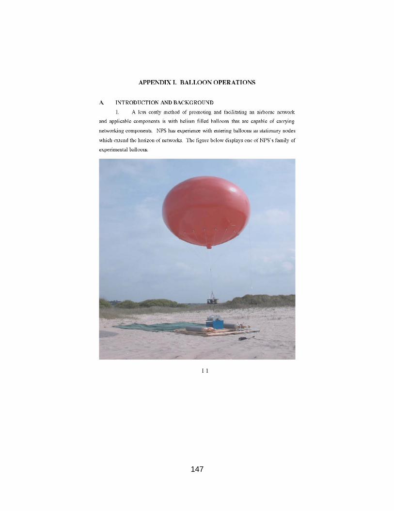
147
148
149

150
151

152
153
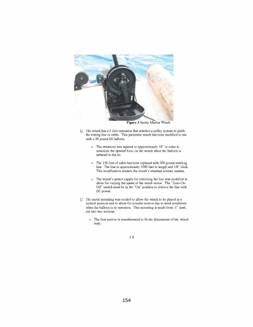
154
155
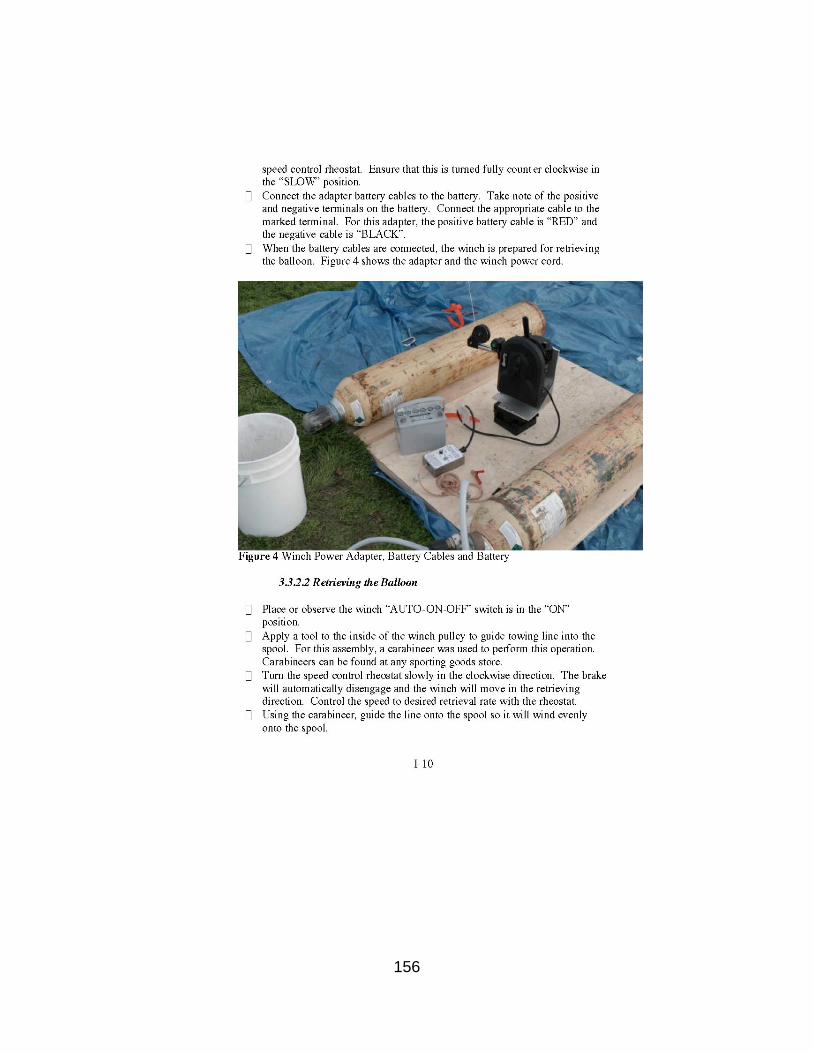
156
157
158

159
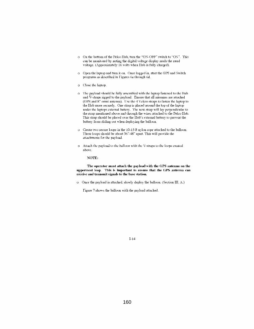
160
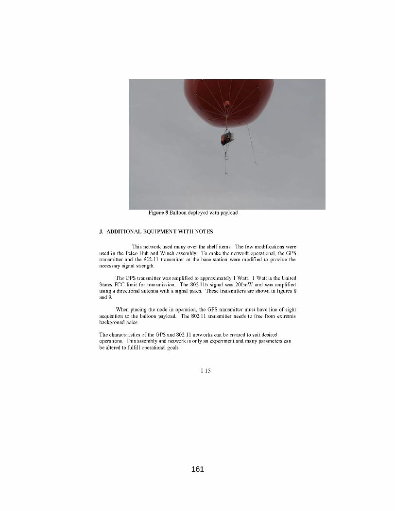
161

162
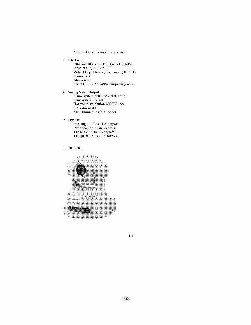
163

164
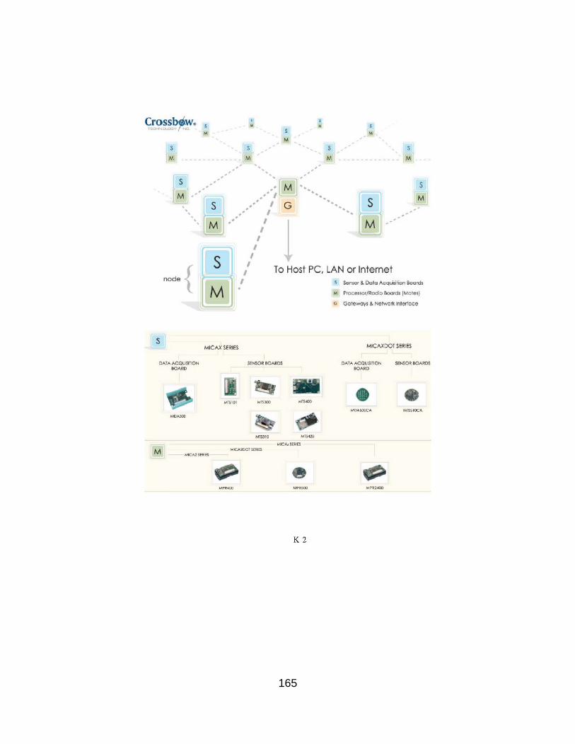
165

166
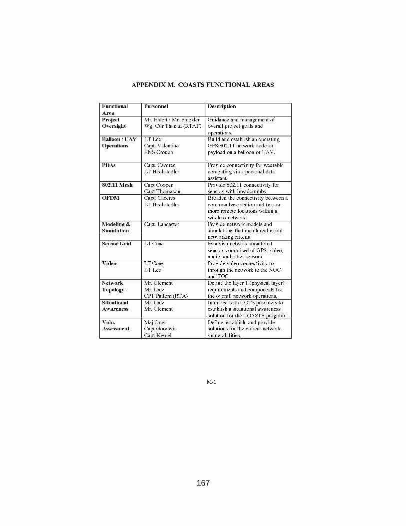
167

168
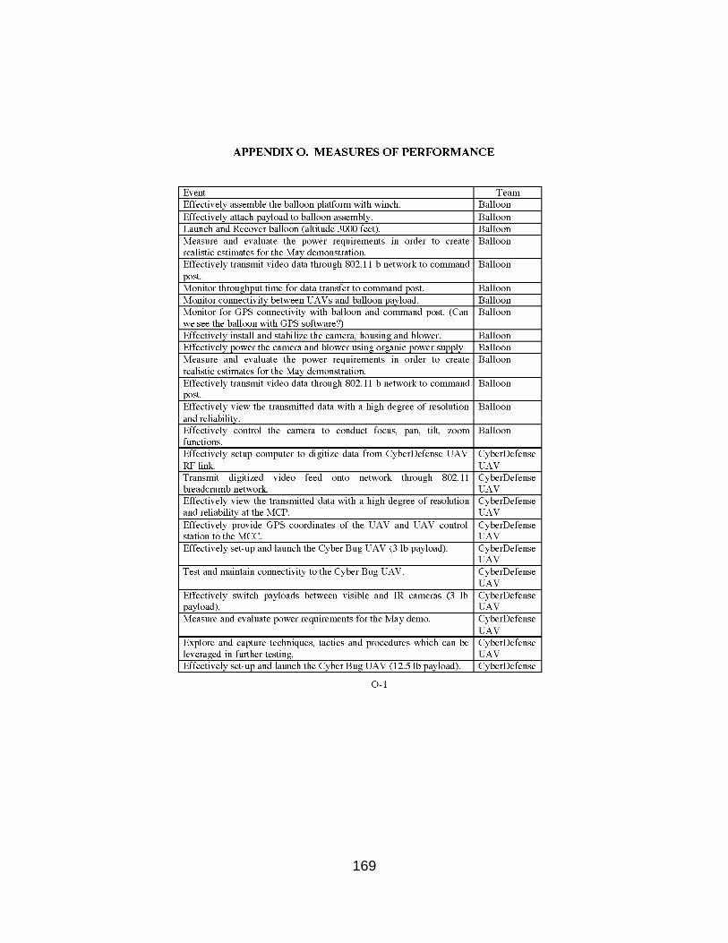
169
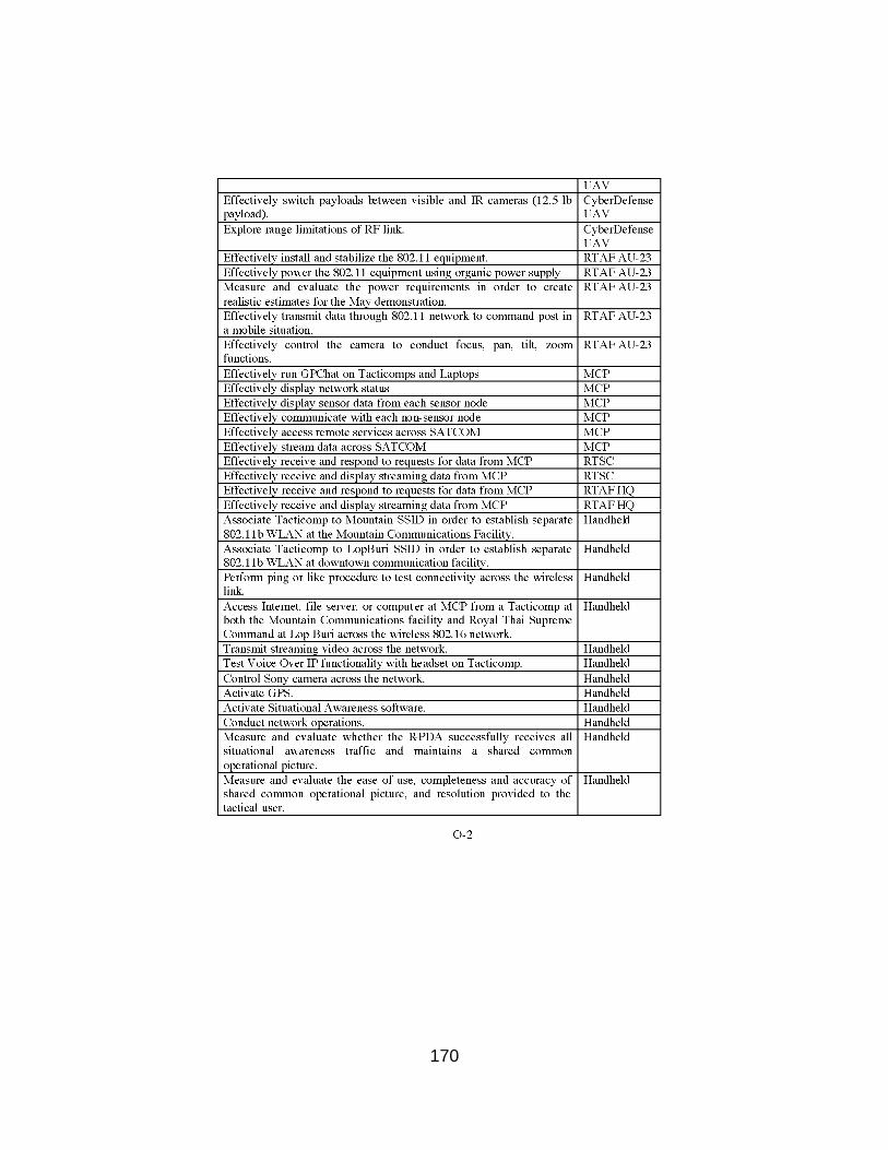
170
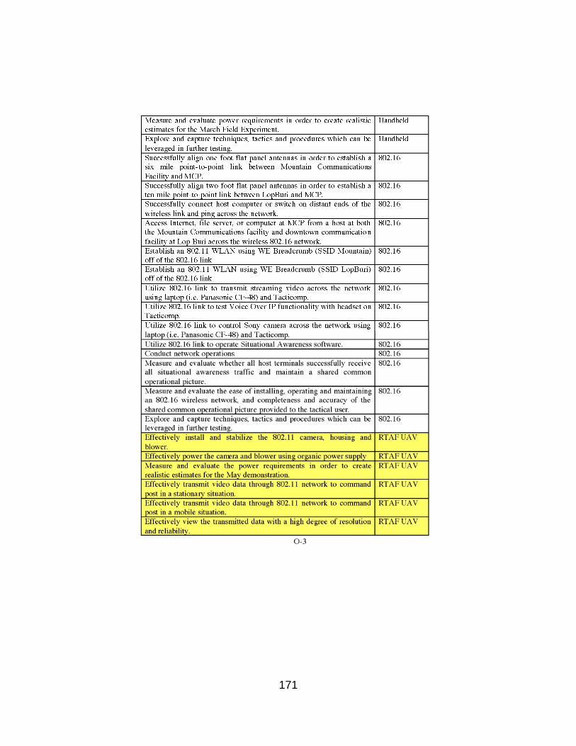
171

172
173
LIST OF REFERENCES
Bigelow, Bruce V. "Air Force Seeking 144 more Predators." The San Diego Union-Tribune 19 Mar 2005. 2 June 2005 <http://www.signonsandiego.com/uniontrib/20050319/news_1b19predator.html>.
Bone, Elizabeth, and Christopher Bolkcom. Report for Congress. Unmanned Aerial Vehicles: Background and Issues for Congress. Congressional Research Service: The Library of Congress, 2003.
Chatwin, Troy. "Spy in the Sky." usmilitary.about.com 23 Feb. 2004. 2 June 2005<http://usmilitary.about.com/cs/armyweapons /a/shadowuav.htm>.
Clement, Michael. Personal Interview. 15 June 2005. Coffey, Timothy, and John A. Montgomery. “The Emergence of Mini UAVs for
Military Applications.” Defense Horizons 22 (2002): 1-8. Fisher, Edward. Personal Interview. 16 June 2005. Grimes, Jeanne. "Desert Hawk enhances security." Globalsecurity.org 30 July
2003. 4 June 2005 <http://www.globalsecurity.org/military/library/news/2003/07/mil-030730afpn01.htm>.
"Hunter RQ-5A Tactical Unmanned Aerial Vehicle, USA/Israel." Army
Technology. 28 Jan 2005. 16 June 2005 <http://www.army-technology.com/projects/hunter/>.
Jane's Unmanned Aerial Vehicles and Targets. Ed. Kenneth Munson. 23rd iss.
Alexandria: Jane's Information Group, 2004. "MAV- Combat Lessons Learned." Defense-update.com 28 Nov. 2004. 2 June
2005 < http://www.defense-update.com/features/du-2-04/mav-oif.htm>.
"Northrop Grumman Hunter UAV Achieves 3,000 Combat Hours in Iraq." Spacedaily.com 27 Nov. 2003. 2 June 2005 <http://www.spacedaily.com/news/uav-03zzh.html>.
"Pointer." UAVForum.com. 2 June 2005
<http://www.uavforum.com/vehicles/production/pointer.htm>.

174
"Pointer Miniature Aerial Vehicle." Defense-update.com 28 Jan. 2005. 2 June 2005 <http://www.defense-update.com/products/p/pointer-uav.htm>.
Reid, Steven E. "Operational Use of the Pioneer Unmanned Aerial Vehicle
(UAV) system." 6 Aug. 1996. 2 June 2005 <http://www.aaicorp.com/pui/opuse.htm>.
"RQ-2A Pioneer Unmanned Aerial Vehicle (UAV)" 28 NOV. 2000. 15 June 2005 <http://www.chinfo.navy.mil/navpalib/factfile/aircraft/air-uav.html>. "Technology Readiness Level." Wikipedia.org. 22 Jan 2005. 16 June 2005 < http://en.wikipedia.org/wiki/Technology_Readiness_Level>. “TESAR (Tactical Endurance Synthetic Aperture Radar).”
Globalsecurity.org 26 Apr. 2005. 2 June 2005 < http://www.globalsecurity.org/intell/systems/tesar.htm>.
"Third Infantry Division (Mechanized) After Action Report - Operation Iraqi
Freedom." Strategy Page. 2005. 14 June 2005 <http://www.strategypage.com/articles/3IDAAR/>.
“UAV Tactical Control System.” Globalsecurity.org 23 Apr. 2005. 2 June 2005
<http://www.globalsecurity.org/intell/systems/uav_tcs.htm>.
United States. Cong. Senate. Committee on Armed Services. National Defense Authorization Act for Fiscal Year 2001. 106th Cong., 2nd sess. S. Rept 106-292, p. 141. Washington: GPO, 2001.
United States. Dept. of the Navy. Office of the Chief of Naval Operations. CNO Guidance for 2005. Jan. 2005. 2 June 2005 <http://www.chinfo.navy.mil/navpalib/cno/clark-guidance2005.pdf>.
United States. Dept of the Navy. Headquarters United States Marine Corps.
Marine Corps Warfighting Publication 3-42.1: Unmanned Aerial Vehicle Operations. 14 Aug. 2003. 2 June 2005 <http://doctrine.usmc.mil>.
United States. Office of the Secretary of Defense. Unmanned Aerial Vehicle Reliability Study. Washington: GPO, 2003.
United States. Office of the Secretary of Defense. Unmanned Aerial Vehicle
Roadmap. Washington: GPO, 2002.

175
BIBLIOGRAPHY
Arquilla, John and David Ronfeldt. Swarming & The Future of Conflict. Santa Monica: RAND, 2000.
Bolkcom, Christopher. Report for Congress. Homeland Security: Unmanned Aerial Vehicles and Border Surveillance. Congressional Research Service: The Library of Congress, 2004.
Clough, Bruce T. "UAV Swarming? So What Are Those Swarms, What Are the Implications, and How Do We Handle Them?". Armed Forces Research Laboratory, 2002.
Federation of American Scientists. Ed. Henry Kelly. 2004. 9 June 2005 <http://www.fas.org>. GlobalSecurity.org. Ed. John E. Pike. 2005. 9 June 2005
<http://www.globalsecurity.org>. Howard, S.P., "Special Operations Forces and Unmanned Aerial Vehicles:
Sooner or Later?" Diss. Air University: School of Advanced Airpower Studies, 1995.
Huber, Arthur F. "Death by A Thousand Cuts: Micro-Air Vehicles in the Service of
Air Force Missions." Air War College: Center for Strategy and Technology: Occasional Paper. 29 (2002).
Quigley, Carroll. Weapons Systems and Political Stability: A History. Washington:
University Press of America, 1983.
United States. Defense Science Board. Unmanned Aerial Vehicles and Uninhabited Combat. Washington: GPO, 2004.
United States. Dept. of the Navy. Navy Tacmemo TM 3-22-5-SW: Integration of
Unmanned Vehicles into Maritime Missions. Washington: GPO, 2005. United States. Office of the Secretary of Defense. Airspace Integration Plan for
Unmanned Aviation. Washington: GPO, 2004. United States. Office of the Secretary of the Navy. Naval Transformation
Roadmap: Power and Access...From the Sea. Washington: GPO, 2002.

176
THIS PLACE INTENTIONALLY LEFT BLANK

177
INITIAL DISTRIBUTION LIST
1. Defense Technical Information Center Ft. Belvoir, Virginia
2. Dudley Knox Library Naval Postgraduate School Monterey, California
3. Mr. James Ehlert Naval Postgraduate School Monterey, California
4. Dr. Bill Kemple Naval Postgraduate School Monterey, California
5. Mr. Edward Fisher
Naval Postgraduate School Monterey, California