national urban search & rescue (us&r) response system
TRANSCRIPT

National Urban Search & Rescue (US&R)
Response System
RESCUE FIELD OPERATIONS GUIDE
US&R-23-FG
15 Sep 2006 US&R-23-FG 1
RESCUE FIELD OPERATIONS GUIDE (ROG) The Federal Emergency Management Agency (FEMA) identifies four levels of operational guidance for use by emergency teams and other personnel involved in conducting or supporting disaster operations. This document corresponds to the level highlighted in bold italics.
Level 1 Overview: A brief concept summary of a disaster-related function, team, or capability.
Level 2 SOP: A complete reference document detailing the procedures for performing a single function (Standard Operating Procedure), or a number of interdependent functions (Ops Manual).
Level 3 Field Operations Guide (FOG ): A durable pocket guide, containing essential nuts-and- bolts information needed to perform specific assignments or functions.
Level 4 Job Aid: A checklist or other aid for job performance or job training.
This document is consistent with and supports the Federal Response Plan for implementation of the Robert T. Stafford Disaster Relief and Emergency Assistance Act, 42 U.S.C. § 5121, et seq. The most current copy of this document, including any change pages, is available through the FEMA Intranet in the National Emergency Management Information System (NEMIS) Reference Library (http://nemis.fema.net), under Response and Recovery/Policies and Guidance, Disaster Operations Guidance.
15 Sep 2006 US&R-23-FG 2
FOREWORD This Rescue Field Operations Guide has been prepared to guide Department of Homeland Security (DHS)/Federal Emergency Management Agency (FEMA) Rescue personnel during Federal disaster response operations. The National Urban Search and Rescue (US&R) Response System provides for the coordination, development, and maintenance of the Federal effort with resources to locate, extricate, and provide immediate medical treatment to victims trapped in collapsed structures; and to conduct other life saving operations. This guide is designed to supplement the National US&R Response System Field Operations Guide, September 2003 (US&R-23-FG) which provides the US&R Response System methods of operation, organization, capabilities, and procedures in mobilization, on-site operations, and demobilization. This guide provides a detailed reference for performing Rescue Operations. The content further elaborates on the content initially provided in US&R-23-FG. Questions, comments, and suggested improvements related to this document are encouraged. Inquiries, information, and requests for additional copies should be directed in writing to the Department of Homeland Security, Federal Emergency Management Agency, Response Division, Operations Branch, 500 C Street SW, Washington, DC 20472

15 Sep 2006 US&R-23-FG 3
Introduction: The Department of Homeland Security (DHS), Federal Emergency Management Agency (FEMA), developed the National Urban Search & Rescue (US&R) Response System to support the Emergency Support Function (ESF) #9 (Urban Search and Rescue) of the Federal Response Plan. Within this framework, resources are mobilized to respond to structural collapse and other incidents nationwide.
Document Purpose: This DHS/FEMA US&R Rescue Operations Guide has been developed to support response resources during training and on missions. This guide supplements the National Urban Search and Rescue Response System FOG, September 2003 (US&R-2-FG). This guide is a compilation and summary of important strategic and tactical information, developed procedures, and reference material specifically for the performance of Rescue Operations.

15 Sep 2006 US&R-23-FG 4
Table of Contents1. Onsite Information
1. Personnel Assignments 2-12. Radio Channels 2-23. Team Briefing Components 2-34. Squad POA Requirements 2-4
2. Position Duties1. RTM General Duties 3-12. RTM On Site Duties 3-2 & 33. RSO General Duties 3-44. RSO On Site Duties 3-55. Blank 3-6
3. Medevac Procedures1. Medevac Procedures 4-1 & 22. Helicopter Hand Signals 4-33. NATO Phonetic Alphabet 4-4
4. BOO Setup1. Requirements 5-12. Priorities 5-23. Assignments 5-34. Responsibilities 5-45. Setup Procedures 5-56. Cache Procedures 5-67. TFCP Procedures 5-78. Medical Procedures 5-89. Shelter Procedures 5-910. Sanitation/Hygiene Procedures 5-1011. Community Tent Procedures 5-1112. Security/Hazards Procedures 5-1213. Tent Assignments 5-1314. Sample Layout 5-14
5. RECON/Marking Systems1. Strategic, Management & Search Markings 6-1 2. Search & Recon Initial Tasks 6-23. Structure ID 6-3 & 44. FEMA Structures/Hazards Marking 6-55. FEMA Search Assessment Marking 6-6 & 76. FEMA Victim Location Marking 6-87. INSARAG Structure Assessment Marking 6-98. INSARAG Victim Location Marking 6-109. Recon Team Make-Up 6-1110. Recon Operations 6-1211. Site Assessment Forms 6-13 & 14

15 Sep 2006 US&R-23-FG 5
Table of Contents (cont.)6. Rescue
1. “LCES” 7-12. Weight, Anchors & Bolting 7-23. Sling Angles 7-34. Sling Arrangements and Safe Working Loads 7-45. Crane Signals 7-56. Cribbing 7-67. Shore Examples
Window/Door Shore 7-7Window/Door Prefab Shore 7-8Temporary “T” Shore 7-9Double “T” Shore 7-10Vertical Shore 7-11Lace Post Shore 7-12Horizontal Shore 7-13Flying Raker Shore 7-14Split Sole Raker – U-Channel Base 7-15Split Sole Raker – Trough Base 7-16Solid Sole Raker 7-1745 Degree Raker Strut Lengths 7-1860 Degree Raker Strut Lengths 7-19Raker Shore Lacing and Bracing 7-20Sloped Floor Shore Perpendicular Type I 7-21Sloped Floor Shore Perpendicular Type II 7-22Sloped Floor Shore Friction 7-23Gusset Plate, Lacing & Bracing Nail Patterns 7-24Cleat Nail Patterns 7-25Split Sole Raker Base Alternatives 7-26
8. Activity Log Forms (2 sided) 8-1 & 29. Miscellaneous Information
Signs, Symptoms & Treatment for Exposure 9-1Directions for Mark I Use 9-2
10. Emergency ProceduresGeneral Cordon Markings 10-1Evacuation Signals 10-2
15 Sep 2006 US&R-23-FG 1 - 1
Personnel Assignments
Rescue Squad:
Squad Personnel
Officer:
1(ASL):
2:
3:
4:
5:
HM:
Medic:
TFL 1: TFL 2:
RTM 1: RTM 2:
LOG 1: LOG 2:
Rescue Squad:
Squad Personnel
Officer:
1(ASL):
2:
3:
4:
5:
HM:
Medic:
TFL 1: TFL 2:
RTM 1: RTM 2:
LOG 1: LOG 2:
15 Sep 2006 US&R-23-FG 1 - 2
Radio ChannelsTFL 1 TFL 2
RTM 1 RTM 2
LOG 1 LOG 2
MED 1 MED 2
BOO 1 BOO 2

15 Sep 2006 US&R-23-FG 1 - 3
Team Briefing Components Situation / Hazard Evaluation:
Operational Period Objectives:
Site Control / Required PPE:
Logistical Support:
Emergency Signals / Procedures:
EMS Plan:
HAZ MAT Concerns:
Communications:
Sketch/Notes:

15 Sep 2006 US&R-23-FG 1 - 4
Squad POA Requirements Sign in/Check in Personal Pack inspection Vehicle keys Contact Information sheet Family Support Team information sheet Medical review/Shot Record MRE/Water Communications equipment issue Passport (if required) Brief Relief issue

15 Sep 2006 US&R-23-FG 2 - 1
Rescue Team Manager
General Duties Reports to TFL Provide input to assist the TFL in
developing the tactical objectives
Coordinate and supervise operations necessary to achieve the tactical objectives
Determine logistical and organizational needs
Receive briefings and SITREPs from TFL
Brief assigned personnel Provide situation updates and maintain
reports
Prepare evaluations for assigned personnel

15 Sep 2006 US&R-23-FG 2 - 2
Rescue Team Manager
On Site Duties
Overall assessment process to determine: • Functional requirements • Work schedules and rotation periods • Adequacy of support facilities
Coordinate activities with Search & Recon Assist in development of team action plan Coordinate objectives and personnel
assignments Ensure proper worksite setup, control &
safety Evaluate operations and modify as needed Evaluate capacity of resources to complete
assignment Order additional resources as needed
15 Sep 2006 US&R-23-FG 2 - 3
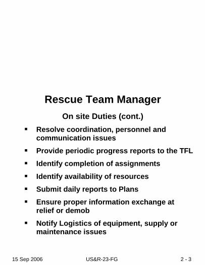
Rescue Team Manager
On site Duties (cont.) Resolve coordination, personnel and
communication issues Provide periodic progress reports to the TFL Identify completion of assignments
Identify availability of resources Submit daily reports to Plans Ensure proper information exchange at
relief or demob Notify Logistics of equipment, supply or
maintenance issues

15 Sep 2006 US&R-23-FG 2 - 4
Rescue Squad Officer
General Duties Reports to Rescue Team Manager
Appoint Assistant Squad Leader (ASL) Implement rescue component of the Team
Action Plan
Coordinate and supervise assigned personnel at worksites
Determine organizational and logistical needs
Provide situation updates and maintain reports
Evaluate and modify rescue tactics and methods as needed
Prepare evaluations for assigned personnel
15 Sep 2006 US&R-23-FG 2 - 5
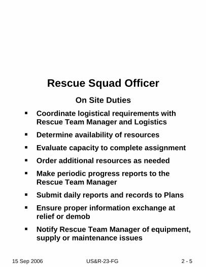
Rescue Squad Officer
On Site Duties Coordinate logistical requirements with
Rescue Team Manager and Logistics Determine availability of resources
Evaluate capacity to complete assignment Order additional resources as needed Make periodic progress reports to the
Rescue Team Manager Submit daily reports and records to Plans Ensure proper information exchange at
relief or demob Notify Rescue Team Manager of equipment,
supply or maintenance issues

15 Sep 2006 US&R-23-FG 2 - 6
NOTES:
_____________________________________________________
_____________________________________________________
_____________________________________________________
_____________________________________________________
_____________________________________________________
_____________________________________________________
_____________________________________________________
_____________________________________________________
_____________________________________________________
_____________________________________________________
_____________________________________________________
_____________________________________________________
_____________________________________________________
_____________________________________________________

15 Sep 2006 US&R-23-FG 3- 1
Medevac Procedures
Select and Secure Landing Site: Size depends on number and type of aircraft Ground slope <15 degrees Ensure surface free of rocks and debris
Avoid dust, sand and snow Ensure ground firm enough to prevent
aircraft from bogging down during loading/unloading
At approach/departure ends, clearly mark obstructions that cannot be removed
Ensure 10:1 horizontal clearance to vertical obstructions
Mark landing/touchdown site Use smoke, signalman and or lights When dark, mark touchdown point with
inverted “Y” composed of four lights

15 Sep 2006 US&R-23-FG 3 - 2
Medevac Procedures
Night Marking of Landing Zones
Note: The touchdown point will be midpoint of the legs of the “Y”. If more than 1 small aircraft will land, add 1 additional light at the exact point each is to land. If more than 1 large aircraft will land, add 2 lights placed 10mm apart aligned in the direction of flight.
Direction of FlightLeft Stem
Right Stem
14 Meters 7 Meters
Direction of FlightDirection of FlightLeft Stem
Right Stem
14 Meters 7 Meters

15 Sep 2006 US&R-23-FG 3- 3
Helicopter Hand Signals
15 Sep 2006 US&R-23-FG 3 - 4
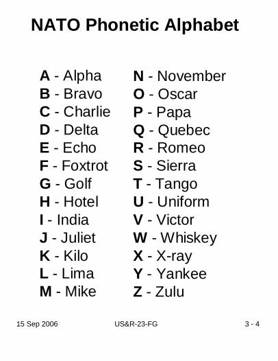
NATO Phonetic Alphabet
A - AlphaB - BravoC - CharlieD - DeltaE - EchoF - FoxtrotG - GolfH - HotelI - IndiaJ - JulietK - KiloL - LimaM - Mike
N - NovemberO - OscarP - PapaQ - QuebecR - RomeoS - SierraT - TangoU - UniformV - VictorW - WhiskeyX - X-rayY - YankeeZ - Zulu

15 Sep 2006 US&R-23-FG 4- 1
BOO Site Requirements
Preferred Size 200x200ft (61x61m) Minimum size 110x150ft (33.5x46m)
Cultural/social considerations Access to work sites
Runoff/flooding Noise considerations Utilities Damaged structures
Prevailing winds/air hazards

15 Sep 2006 US&R-23-FG 4 - 2
BOO Setup Priorities
TaskCache setup and organizationTask Force Command CenterMedicalPersonnel SheltersSanitation/HygieneCommunity TentCanine ShelterSecurity/Hazards (constant)
Priority1111233
N/A

15 Sep 2006 US&R-23-FG 4- 3
BOO Setup Assignments
Squad 1:Assigned to tent ________________
Squad 2:Assigned to tent ________________Personnel Shelter setup (Priority 1)
Squad 3:Assigned to tent ________________Cache setup & organization (Priority 1)
Squad 4:Assigned to tent ________________Cache setup & organization (Priority 1)

15 Sep 2006 US&R-23-FG 4 - 4
BOO Setup Responsibilities Site Requirements (Immediate)
• Task Force Leader, Rescue Team Manager, Log Chief & Comm Specialists
Cache Setup and Organization (Priority 1) • Log Chief, Log Specialists, Squads 3 & 4
TFCC Setup (Priority 1) • Task Force Leader, Plans Chief, Comm
Specialists, Technical Info Specialist & Safety Medical Treatment Area Setup (Priority 1)
• Medical Manager & Medical Specialists Personnel Shelter Setup (Priority 1)
• Squad 2 Sanitation/Hygiene Issues (Priority 2)
• Safety Canine Exercise Area (Priority 3)
• Search Team Manager & Canine Specialists
Community Tent Setup (Priority 3) • Log Chief & Technical Info Specialist

15 Sep 2006 US&R-23-FG 4- 5
BOO Setup Procedures Preferred Size, 200x200ft (61x61m) Minimum Size, 110x150ft (33.5x46m) Utilize Advance Team Kit
• 2 - 100ft tapes, roll fireline tape, BOO signs, digital camera, vests, chalk, binoculars & paint
Layout and identify sections with signs and fireline tape
Entrance should be adjacent to main access or travel route
Mark ground for location, dimension and spacing of each section and tent
Identify travel/access routes Ensure fire extinguishers and signs are present
Generators placed on perimeter near section to be powered
Identify remote fuel storage area Post signs for all sections and each tent

15 Sep 2006 US&R-23-FG 4 - 6
BOO Setup (Cache) Procedures Size (approximately) 50x60ft (15x18m) Layout/mark Cache area adjacent to BOO
entrance and main travel/access Post conspicuous sign Mark perimeter with fireline tape and establish
entry control point Mark location/layout for cache setup
• 4 rows Rescue
• 1 row Technical
• 1 row WMD (as needed)
• 1 row Logistics Erect 19x35ft Western Shelter tent for weather
sensitive equipment and office Provide electricity and light Identify empty boxes for counter space/seating Provide tarps/sheeting for weather/security

15 Sep 2006 US&R-23-FG 4- 7
BOO Setup (TFCP) Procedures
Size (approximately) 40x30ft (12x9m) Mark perimeter with fireline tape and post sign
Identify high ground/elevated structures for communications
Erect 2 19x19ft Western Shelter tents
Provide electricity and light Retrieve/setup all office supplies and forms Establish the following:
• Command and Control
• Workspace
• Communications
• Equipment setup
• Plans/Technical Information workspace

15 Sep 2006 US&R-23-FG 4 - 8
BOO Setup (Medical) Procedures
Size (approximately) 25x50ft (7.5x15m) Mark perimeter with fireline tape and post sign
Erect 19x35ft Western Shelter tent Provide electricity and light Establish the following:
• Patient treatment area, with privacy
• Acute care equipment
• Office workspace with shelving and seating

15 Sep 2006 US&R-23-FG 4- 9
BOO Setup (Shelter) Procedures
Size (approximately) 80x110ft (24x33.5m) Mark perimeter with fireline tape and post sign
Erect Personnel Shelter tents Provide electricity and lighting Provide smoke & carbon monoxide detectors
and fire extinguishers Affix identification signs to tents Consider weather and runoff issues
15 Sep 2006 US&R-23-FG 4 - 10
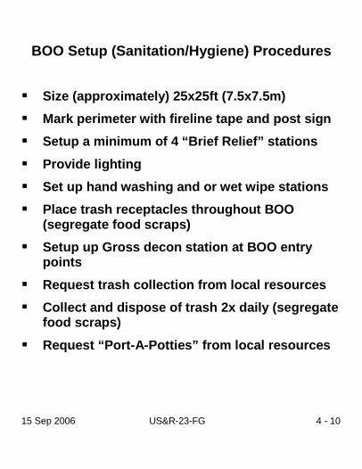
BOO Setup (Sanitation/Hygiene) Procedures
Size (approximately) 25x25ft (7.5x7.5m) Mark perimeter with fireline tape and post sign Setup a minimum of 4 “Brief Relief” stations
Provide lighting Set up hand washing and or wet wipe stations Place trash receptacles throughout BOO
(segregate food scraps) Setup up Gross decon station at BOO entry
points
Request trash collection from local resources Collect and dispose of trash 2x daily (segregate
food scraps)
Request “Port-A-Potties” from local resources
15 Sep 2006 US&R-23-FG 4- 11
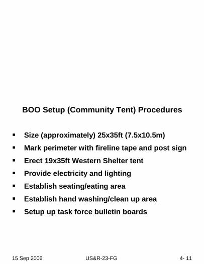
BOO Setup (Community Tent) Procedures
Size (approximately) 25x35ft (7.5x10.5m) Mark perimeter with fireline tape and post sign
Erect 19x35ft Western Shelter tent Provide electricity and lighting Establish seating/eating area
Establish hand washing/clean up area Setup up task force bulletin boards

15 Sep 2006 US&R-23-FG 4 - 12
BOO Setup (Security/Hazards) Procedures
Identify/Mark Hazards within or adjacent to the BOO
Isolate fuel storage Provide fire extinguisher at fuel storage and
refueling locations Post “No Smoking” signs as appropriate Cover cache, supplies and equipment as
appropriate Request additional generators/lighting for
improved safety/security
Post and announce plan for evacuation and assembly points
Identify availability of local police/military

15 Sep 2006 US&R-23-FG 4- 13
BOO Setup Tent Assignments
AssignmentTFL, RTM, Safety, Plans, TIS ENGTFL, RTM, Safety, Plans, TIS ENGSquad 3 & HM SpecialistSquad 1 & HM SpecialistSquad 4 & Driver/MechanicSquad 2 & Driver/MechanicCanine Specialists & CaninesSTM, Search Specs. & HER Spec.Non-Task Force PersonnelMedical PersonnelCommunications PersonnelLogistics Personnel
TentABCDEFGHI
MedicalComm
Log

15 Sep 2006 US&R-23-FG 4 - 14
Tent Assignments and Sample Layout
A
B
C
D E F
G
H
IMedical
Log
Community
Comm
Command
Head &Shower
BootWash
Gen
Wash
Wash Gen
Gen
Cache
A
B
C
D E F
G
H
IMedical
Log
Community
Comm
Command
Head &Shower
BootWash
Gen
Wash
Wash Gen
Gen
Cache

15 Sep 2006 US&R-23-FG 5- 1
Strategic Considerations The most effective rescue strategy should blend all viable tactical capabilities into a logical plan of operation. The general strategic considerations are outlined as follows: Rescue Site Management and Coordination Each rescue work site must have one person in charge to maintain unity of command. The Rescue Squad Officer of each rescue squad is responsible for all activities of the assigned rescue site including safety when a single squad operates alone. At large or complex rescue operations that require the commitment of two or more rescue squads to a single operation, the Rescue Team Manager may assume command or assign one of the Rescue Squad Officers to be in charge of the site. A Safety Officer should be identified at each rescue site. Search Phases There are generally five phases of organized search and rescue operations at collapse incidents:
Phase One: Assessment of the collapse area.
Phase Two: Removal of all surface victims as quickly and safely as possible.
Phase Three: Search and rescue of victims from accessible void spaces.
Phase Four: Selected debris removal to locate and rescue victims.
Phase Five: General debris removal. Usually conducted after all known victims have been removed.
15 Sep 2006 US&R-23-FG 5 - 2
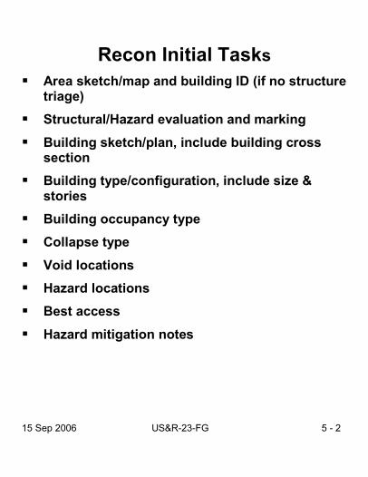
Recon Initial Tasks
Area sketch/map and building ID (if no structure triage)
Structural/Hazard evaluation and marking
Building sketch/plan, include building cross section
Building type/configuration, include size & stories
Building occupancy type Collapse type
Void locations Hazard locations Best access
Hazard mitigation notes

15 Sep 2006 US&R-23-FG 5- 3
Structure Identification
If no numbers known, use low #’s
800 900 1000Block Alpha Street
900 902 904 906 908
901 903 905 907 909

Structure Identification (Cont.)
Basement 3Basement 3
Floor 3Floor 2Floor 1
Basement 1Basement 2
Ground Level
Floor 3Floor 2Floor 1
Basement 1Basement 2
Ground Level
CB D
AFront
CB
AFront
Floor ID
Quad B Quad C
Quad D
Quad E
FrontQuad A
Quad B
D
Side ID
Quadrant ID
Quad C
Quad D
Quad E
Front
(Use arrow to designate best entry point)
15 Sep 2006 US&R-23-FG 5 - 4

15 Sep 2006 US&R-23-FG 5- 5
FEMA Structures/Hazards Marking
2x2ft (60x60cm)Structure relatively safe for US&R operations
Structure significantly damagedShoring/removal of hazards may be required
Structure not safe for normal US&R operationsExtensive safety measures must be taken before entry
To right of box:DateHazardsTimeTF ID
28 JUN 03NATURAL GAS
1432HRSNE-TF1
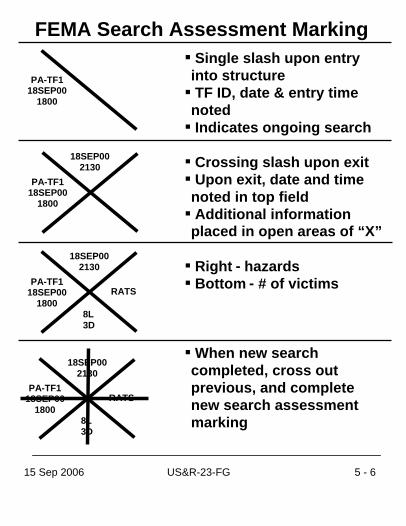
FEMA Search Assessment MarkingSingle slash upon entry into structureTF ID, date & entry time notedIndicates ongoing search
Crossing slash upon exitUpon exit, date and timenoted in top fieldAdditional information placed in open areas of “X”
Right - hazardsBottom - # of victims
When new search completed, cross out previous, and complete new search assessment marking
RATS
18SEP00 2130
PA-TF1 18SEP00
1800 8L 3D
RATS
18SEP00 2130
PA-TF1 18SEP00
1800 8L 3D
RATS
18SEP00 2130
PA-TF1 18SEP00
1800 8L 3D
PA-TF1 18SEP00
1800
15 Sep 2006 US&R-23-FG 5 - 6

15 Sep 2006 US&R-23-FG 5- 7
RATS
18SEP00 2130
PA-TF1 18SEP00
1800
8L 3D
F 1- 4F 5 Q A/B
or No Entry
FEMA Search Assessment MarkingIncomplete Search Marking
When search terminated prior to completion:
Place filled circle at center of slash Add date & time search terminated in top fieldNote hazards to rightNote victims beneathPlace box below slash, & Note areas searched
Use “F” to ID floors searched
Use “Q” to ID quadrants searched
If only searched Exterior, as in Hurricane,write “No Entry” in box

V
CA- TF2
V
CA- TF2
FEMA Victim Location Marking“V” indicates potential victim locationArrow may be used to pinpoint location, add distance on arrow.
Line through “V” indicates
confirmed deceased victim.If more than one, mark total number under V.
Circle around “V” indicates confirmed livevictim. If more than one,mark number under V.
Cross out marking whenvictim is removed.
V
CA- TF2
5’
2
2
V
CA- TF2
2V
CA- TF2CA- TF2
215 Sep 2006 US&R-23-FG 5 - 8

15 Sep 2006 US&R-23-FG 5- 9
Team ID
Time/Date of startTime/Date of end
G or N(Go/No Go)
Hazard information
Persons unaccounted for:Location of other victims:
Numberof livevictims
removed
Numberof deadvictims
removed
*When operation is completed, the box is circled.
INSARAG Structure Assessment Marking

15 Sep 2006 US&R-23-FG 5 - 10
V
VV
VL - 4D - 3
VL - 4D - 3
VL - 4D - 3
VVL - 4D - 3
INSARAG Victim Location Marking“V” near location of known or potential victims
Below “V”:Place “L” & # to denote live victimsPlace “D” & # to denote dead victims
Draw arrow to pinpoint confirmed victimConfirmation must be visual or audible, canine cannot confirm
Circle marking when last live victim is removed orplace line through “V” when only dead victims remain
15 Sep 2006 US&R-23-FG 5- 11
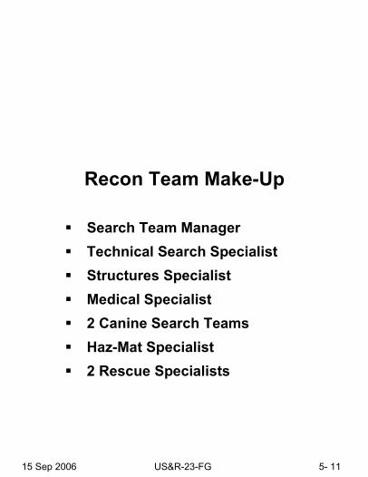
Recon Team Make-Up
Search Team Manager Technical Search Specialist Structures Specialist Medical Specialist 2 Canine Search Teams Haz-Mat Specialist 2 Rescue Specialists

15 Sep 2006 US&R-23-FG 5 - 12
Recon Operations
Identify buildings Structure/hazards marking Area/building search Search/assessment marking Assess void space and atmospheric
conditions Victim location identification Sketch search area and record information Communicate findings to appropriate
manager

15 Sep 2006 US&R-23-FG 5- 13
Site AssessmentDate: Time: Site#:
Type of Occupancy:GPS:# of levels: Above ground:Below ground:Possible # of victims/location:
Hazards:
Utilities controlled:Electricity WaterGas Other
Date: Time: Site#:
Type of Occupancy:GPS:# of levels: Above ground:Below ground:Possible # of victims/location:
Hazards:
Utilities controlled:Electricity WaterGas Other

15 Sep 2006 US&R-23-FG 5 - 14
Other assets on site:
Witness reports/Intel/Notes:
Sketch:

15 Sep 2006 US&R-23-FG 5- 13
Site AssessmentDate: Time: Site#:
Type of Occupancy:GPS:# of levels: Above ground:Below ground:Possible # of victims/location:
Hazards:
Utilities controlled:Electricity WaterGas Other
Date: Time: Site#:
Type of Occupancy:GPS:# of levels: Above ground:Below ground:Possible # of victims/location:
Hazards:
Utilities controlled:Electricity WaterGas Other

15 Sep 2006 US&R-23-FG 5 - 14
Other assets on site:
Witness reports/Intel/Notes:
Sketch:

15 Sep 2006 US&R-23-FG 6- 1
LCES Lookouts
• Appoint site Safety Officer
• Observe only
Communications • Request radio channel(s)
• Review evacuation signals
Escape Routes • Pre-established path to safe area
Safe Zones • Pre-established areas of refuge
• Pre-identified assembly area
15 Sep 2006 US&R-23-FG 6 - 2
Preferred depth
150 pcf (67kg)
Weights of Common Building MaterialsReinforced Concrete Slabs
Masonry
Wood
Steel
Concrete or Masonry Rubble
125 pcf (56kg)
35 pcf (15kg)
490 pcf (220kg)
10 psf (4kg pe
r inch of depth)
Anchors and Bolting
Minimum edge distance
Minimum spacing
Minimum depth
6x diameter of bolt
12x diameter of bolt
6x diameter of bolt
9x diameter of bolt
15 Sep 2006 US&R-23-FG 6- 3
Effects of Sling Angles
1000 lbs
450 kg
1000lbs
450 kg
1000lbs
450 kg
1000lbs
450 kg
90Degree
60Degree
45Degree
30Degree
500 lbs225 kg
575 lbs258 kg
707 lbs318 kg
1000 lbs450 kg
Amount of load on each leg

15 Sep 2006 US&R-23-FG 6 - 4
Sling Arrangements and Design Loads
Vertical1 x
Rating
Basket2 x
Rating
Choker3/4 x
Rating
Vertical1 x
Rating
Basket2 x
Rating
Choker3/4 x
Rating

15 Sep 2006 US&R-23-FG 6- 5
CRANE SIGNALS

15 Sep 2006 US&R-23-FG 6 - 6
Cribbing
4x4 - 6000lbs (2700kg) per full contact point
6x6 - 15,000lbs (6750kg) per full contact point
Overlap corners by 4” (10cm)
Up to 15 degree slope max. (3 feet in 10 feet)
Allowable Height to Width Ratios All bearing
Lifting or moving
2 of 4 bearing
1 of 4 bearing
3 to 1
2 to 1
1.5 to 1
1 to 1
15 Sep 2006 US&R-23-FG 6- 7
Window/Door1 - Header1 - Sole plate2 - Posts4 - Pair 2x4 wedges1 – Triangle Gusset3 - Cleats2 - Diagonals
At least 1” (2.5cm) of header depth for each foot of horizontal opening spanned. (4x4 minimum)
15 Sep 2006 US&R-23-FG 6 - 8
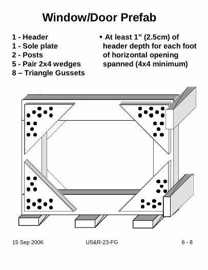
Window/Door Prefab1 - Header1 - Sole plate2 - Posts5 - Pair 2x4 wedges8 – Triangle Gussets
At least 1” (2.5cm) of header depth for each foot of horizontal opening spanned (4x4 minimum)

15 Sep 2006 US&R-23-FG 6- 9
Temporary “T”
1 - Header1 - Sole plate1 - Post1 - Pair 2x4 wedges2 – Full-Gusset plates1 – Half-Gusset or Cleat
Up to 11 ft (240cm) for 4x4Up to 16 ft (360cm) for 6x63 ft header (90cm) gets 12x12 (30x30xcm) gusset plates

Double “T”1 - Header1 - Sole plate
2 - Posts2 - Pair 2x4 wedges3 – Dbl-Gusset plates 12x24
(30x60cm) 2 – Half-Gussets or Cleats
Up to 12 ft (240cm) for 4x4Up to 18 ft (360cm) for 6x63 ft header (90cm) Post Spacing is 18 to 24inches out to out
15 Sep 2006 US&R-23-FG 6 - 10

15 Sep 2006 US&R-23-FG 6- 11
1 - Header1 - Sole plate3 - Posts3 - Pair 2x4 wedges5 – Half- Gussets2 – 2x6 Diagonals Mid point brace ifneeded, use 1x6or ¾” x 6” ply strip
Post spacing is 1ft per 1in of header depth on center (3-4ft or 90-120cm)
Overhand of 1ft (30cm) Mid point brace needed for:
4x4 over 8ft (240cm) tall 6x6 over 12ft (360cm) tall
Vertical

15 Sep 2006 US&R-23-FG 6 - 12
Laced Post
Post spacing is 3 to 5 feet (90 to 150cm)1 ft (30cm) overhangLacing/bracing is 2x4 for 4x4Lacing/bracing is 2x6 for 6x6Add one horizontal & one diagonal to each side if over 11 ft (330cm) tall
2 - Headers2 - Sole plates4 - Posts8 - Horizontals4 - Pair 2x4 wedges8 - Diagonals8 – Half- Gussets

15 Sep 2006 US&R-23-FG 6- 13
Horizontal2 - Wall plates3 - Struts3 - Pair 2x4 wedges7 - 4x4 wedges (9 if bottom strut not on floor)1- Half-gusset (or Cleat)2 - Diagonals1 - Cleat
Shims go on undamaged side

15 Sep 2006 US&R-23-FG 6 - 14
Flying Raker1 - Wall Plate1 - Raker strut1 - Cleat2 – Full- Gussets2 - 2x6 Horizontal Braces1 - U Channel Foot 1 - Pair 2x4 or 4x4 wedges

15 Sep 2006 US&R-23-FG 6- 15
Split Sole Raker – U-Channel Base1 - Wall Plate1 - Raker Strut1 - Cleat2 – Full- Gussets2 - 2x6 Horizontal Braces2 - 2x6 Mid Point Braces1 - U Channel1 - Sole Plate1 - Pair 2x4 wedges ( 4x4 if needed)
U-ChannelSee Page 6- 26
15 Sep 2006 US&R-23-FG 6 - 16
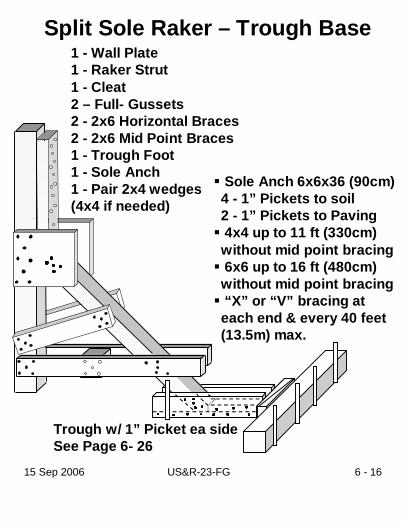
Split Sole Raker – Trough Base
Sole Anch 6x6x36 (90cm) 4 - 1” Pickets to soil 2 - 1” Pickets to Paving 4x4 up to 11 ft (330cm) without mid point bracing6x6 up to 16 ft (480cm) without mid point bracing“X” or “V” bracing at each end & every 40 feet (13.5m) max.
1 - Wall Plate1 - Raker Strut1 - Cleat2 – Full- Gussets2 - 2x6 Horizontal Braces2 - 2x6 Mid Point Braces1 - Trough Foot 1 - Sole Anch1 - Pair 2x4 wedges (4x4 if needed)
Trough w/ 1” Picket ea sideSee Page 6- 26

15 Sep 2006 US&R-23-FG 6- 17
Solid Sole Raker1 - Wall plate1 - Sole plate1 - Strut2 - Cleats6 – Full- Gussets2 - 2x6 diagonals1 - Pair 2x4 or 4x4 wedges
4x4 up to 11 ft (330cm) without mid point bracing6x6 up to 16 ft (480cm) without mid point bracing“X” or “V” bracing at each end & every 40 feet (13.5m) max.
15 Sep 2006 US&R-23-FG 6 - 18
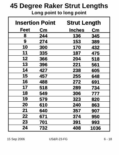
45 Degree Raker Strut LengthsLong point to long point
Insertion Point Strut LengthFeet
89101112131415161718192021222324
Cm244274300335366396427457488518549579610640671701732
Inches136153170187204221238255272289306323240357374391408
Cm3453894324755185616056486917347778208639079509931036
Insertion Point Strut LengthFeet
89101112131415161718192021222324
Cm244274300335366396427457488518549579610640671701732
Inches136153170187204221238255272289306323240357374391408
Cm3453894324755185616056486917347778208639079509931036

15 Sep 2006 US&R-23-FG 6- 19
60 Degree Raker Strut LengthsLong point to long point
Insertion Point Strut LengthFeet
89101112131415161718192021222324
Cm244274300335366396427457488518549579610640671701732
Inches112126140154168182196210224238252266280294308322336
Cm284320356391427462498533569605640676711747782818853
Insertion Point Strut LengthFeet
89101112131415161718192021222324
Cm244274300335366396427457488518549579610640671701732
Inches112126140154168182196210224238252266280294308322336
Cm284320356391427462498533569605640676711747782818853
15 Sep 2006 US&R-23-FG 6 - 20
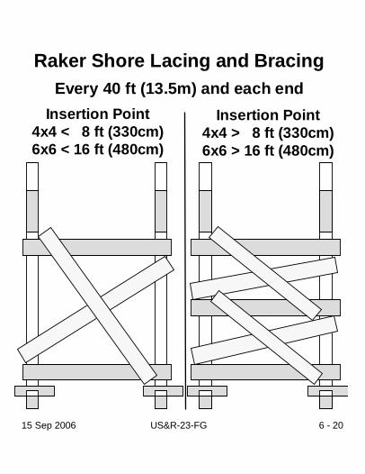
Raker Shore Lacing and BracingEvery 40 ft (13.5m) and each end
Insertion Point4x4 < 8 ft (330cm)6x6 < 16 ft (480cm)
Insertion Point4x4 > 8 ft (330cm)6x6 > 16 ft (480cm)

15 Sep 2006 US&R-23-FG 6- 21
Sloped Floor ShorePerpendicular - Type I
Used when slope is over 3 degrees (6 inches in 10 feet)Pairs placed up to 8 ft (240cm)Sloped floor/structure must be attached at top or bottom2x6 horizontal & diag. “X” bracing¾” plywood with a min. width of 12” (30cm) and a max. length of 5 ft (152cm), may replace bracing on short side with a min. of 11 - 8d nails to each post
1 - Header2 - Posts2 - U Channels2 - 2x6 Diagonals1 - Horizontals2 – Half-gussets2 - U Channels2 - Pair 2x4 wedges2 - Sole plates

15 Sep 2006 US&R-23-FG 6 - 22
Sloped Floor ShorePerpendicular - Type II
1 - Header1 - Sole plate2 - Posts4 - Cleats2 - Half-gussets2 - 2x6 diagonals2 - Pair 2x4 wedges
Used when slope is over 3 degrees (6 inches in 10 feet) Slope pairs placed up to 8 ft (240cm)2x6 horizontal and diag. “X” bracingSloped floor/structure must be attached at top or bottom¾” plywood with a min. width of 12” (30cm) and a max. length of 5 ft (152cm), may replace bracing on short side with a min. of 11 - 8d nails to each post

15 Sep 2006 US&R-23-FG 6- 23
Sloped Floor Shore Friction - Type III
1 - Header1 - Sole plate2 - Posts2 - Cleats4 - Half-gussets2 - 2x6 Diagonals2 - Pair 2x4 wedges
Used when slope is over 3 degrees (6 inches in 10 feet) Pairs placed up to 8 feet(240cm) on centerHeader must be attached to sloped surface over 5 degree slope2x6 horizontal & diag. “X” bracing¾” plywood with a min. width of 12” (30cm) and a max. length of 5 ft (152cm), may replace bracing on short side with a min. of 11- 8d nails to each post

15 Sep 2006 US&R-23-FG 6 - 24
Lacing and Bracing Nail Patterns
Raker, Full - Gusset Plate Nail Patterns
12 x 12”(30x30cm)5 and 8 8d nails
12 x 12”(30x30cm)5 and 8 8d nails
2x4, 3 - 16d nails 2x6, 5 - 16d nails2x4, 3 - 16d nails 2x6, 5 - 16d nails
Triangle & Half- Gusset Plate Nail Patterns
12” (30cm)triangle5 and 88d nails
6 x12”(15x30cm)4 and 4 8d nails
12” (30cm)triangle5 and 88d nails
6 x12”(15x30cm)4 and 4 8d nails
T and Dbl-T Nail Patterns
12 x 12”(30x30cm)5 and 8 8d nails
12 x24”(30x60cm)5 - 8d to Posts14 - 8d to Header
12 x 12”(30x30cm)5 and 8 8d nails
12 x24”(30x60cm)5 - 8d to Posts14 - 8d to Header

15 Sep 2006 US&R-23-FG 6- 25
Cleat Nail Patterns
2x4x24 (60cm) 14 - 16d nails45 deg Raker
2x4x30 (75cm) 20 - 16d nails60 deg Raker
2x6x24 (60cm) 20 - 16d nails45 deg Raker
2x6x30 (75cm) 29 - 16d nails60 deg Raker

15 Sep 2006 US&R-23-FG 6 - 26
Split Sole Base Alternatives(may also be used for Flying Raker)
U-Channel4x4x18 (45cm)12x12x3/4 (30x30cm) ea side8 - 8d nails ea side
Trough2x6x48 (120 cm) ea side2x4x48 (120 cm)7 - 16d nails ea side2x4x18 (45cm) flush w/end3 - 16d nails ea side
Trough with Sole Anchor6x6x36 min (90cm)may be continuous between Rakers4 - 1” Pickets into Soil at Sole Anch(2 - 1” Pickets into Paving)1 - Picket ea side Trough(1”x 48” (120cm) Pickets)Pair 2x4 or 4x4 wedges

15 Sep 2006 US&R-23-FG 7 - 1
Unit Activity Log 1. Incident Name: 2. Date: 3. Time:
ICS 214
4. Rescue Squad: 5. Leader: 6. Operational Period:
7. Rescue Squad Roster
RS 1 (ASL):
RS 2:
RS 3:
RS 4:
RS 5:
HazMat:
Medic:
8. Activity Log (cont. on reverse)
Time: Major Events:
Unit Activity Log 1. Incident Name: 2. Date: 3. Time:
ICS 214
4. Rescue Squad: 5. Leader: 6. Operational Period:
7. Rescue Squad Roster
RS 1 (ASL):
RS 2:
RS 3:
RS 4:
RS 5:
HazMat:
Medic:
8. Activity Log (cont. on reverse)
Time: Major Events:

15 Sep 2006 US&R-23-FG 7 - 2
Time: Major Events:

15 Sep 2006 US&R-23-FG 7 - 1
Unit Activity Log 1. Incident Name: 2. Date: 3. Time:
ICS 214
4. Rescue Squad: 5. Leader: 6. Operational Period:
7. Rescue Squad Roster
RS 1 (ASL):
RS 2:
RS 3:
RS 4:
RS 5:
HazMat:
Medic:
8. Activity Log (cont. on reverse)
Time: Major Events:
Unit Activity Log 1. Incident Name: 2. Date: 3. Time:
ICS 214
4. Rescue Squad: 5. Leader: 6. Operational Period:
7. Rescue Squad Roster
RS 1 (ASL):
RS 2:
RS 3:
RS 4:
RS 5:
HazMat:
Medic:
8. Activity Log (cont. on reverse)
Time: Major Events:

15 Sep 2006 US&R-23-FG 7 - 2
Time: Major Events:

15 Sep 2006 US&R-23-FG 8 - 1
Signs and Symptoms of Nerve Agent ExposureMILD
HeadacheBlurred vision/pinpoint pupilsTight chest
MODERATELY SEVERE Severe chest tightness
VERY SEVERE Bluish discoloration of skinRespiratory failureComa
Excessive sweatingTearingSalivationUnexplained runny nose
Diarrhea (rare)
UnconsciousSeizures
Must have no doubt of exposure and the need for treatment. Use these drugs only on symptomatic, contaminated personnelDepending on severity of symptoms, immediately administer 1 atropine auto-injector, followed by 1 “2-PAM Cl” auto-injector If signs and symptoms still exist after 5–10 mins, repeat injections If signs and symptoms still exist after additional 10 mins, repeat injections for third time If signs and symptoms remain after third set of injections, do not give any more antidotes but seek immediate medical help
If Severe Signs and Symptoms are Present:All three auto-injector kits (atropine and “2-PAM Cl”) should be administered in rapid successionIf patient is actively seizing, Valium (10mg) should be administered
Treatment For Exposure
UrinationMuscular Twitching
“SLUDGEM”Salivation
GI upset (cramps)
Lacrimation
Emesis
Defecation
“SLUDGEM”Salivation
GI upset (cramps)
Lacrimation
Emesis
Defecation

15 Sep 2006 US&R-23-FG 8 - 2
Mark I Kit Directions for UsePartner Antidote Administration
Antidote administration primarily responsibility of your partner
Antidote self-administration is the exception(to be accomplished only under extraordinary circumstances)!
Agent exposure does not necessarily mandate antidote administration!
Remove safety cap (yellow on atropine; gray on “2-PAM Cl”). Mark I kit clip holds the safety caps; may not notice if using Mark I kits. Do not touch colored end of injector after removing cap; injector can and will function into fingers or hand if any pressure applied to this end of injector
Hold injector like a pen. Place colored end (green on atropine, black on “2-PAM Cl”) on thickest part of thigh and press hard until injector functions
Hold firmly in place for ten seconds, then remove. Massage the area of injection
15 Sep 2006 US&R-23-FG 8 - 3
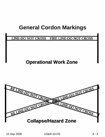
General Cordon Markings
LINE-DO NOT CROSS FIRE LINE-DO NOT CROSS
Operational Work Zone
RE LINE-DO NOT CROSS FIRE LINE-DO NOT CROSSRE LINE-DO NOT CROSS FIRE LINE-DO NOT CROSS
Collapse/Hazard Zone
LINE-DO NOT CROSS FIRE LINE-DO NOT CROSSLINE-DO NOT CROSS FIRE LINE-DO NOT CROSS
Operational Work Zone
RE LINE-DO NOT CROSS FIRE LINE-DO NOT CROSSRE LINE-DO NOT CROSS FIRE LINE-DO NOT CROSSRE LINE-DO NOT CROSS FIRE LINE-DO NOT CROSSRE LINE-DO NOT CROSS FIRE LINE-DO NOT CROSS
Collapse/Hazard Zone

15 Sep 2006 US&R-23-FG 8 - 4
Evacuation Signals
Evacuate • 3 Short blasts • (Continually until all out) • (1 Second each)
Cease Operations
• 1 Long blast • (3 Seconds)
Resume Operations
• 1 Long and 1 short blast Note if different: