nat 5 gc paper 3 - lhs technical · (6 marks) geometric forms ... grid and snap to grid. state two...
TRANSCRIPT

St. Augustine’s R. C. High School CDT Department
Mark
Graphic Communication
Date — December 2013
Duration — 1 hour and 30 minutes
Fill in these boxes and read what is printed below.
Name Form Class
Teacher Class Set
Total marks - 60
Attempt ALL questions.
All dimensions in mm.
All technical sketches use 3rd angle projection.
You may use rulers, compasses or trammels for measuring.
Read every question carefully before you attempt it.Write your answers clearly in the spaces provided, using blue or black ink.
Before leaving the examination room you must give your answer booklet to the Invigilator.If you do not, you may lose all the marks for this paper.
NationalQualificationsN5
1

1. A graphic designer has produced three promotional layouts.
(a)
(i) State one instance where alignment has been usedin Layout 1. (1 mark)
_________________________________________________
_________________________________________________
_________________________________________________
_________________________________________________
_________________________________________________
_________________________________________________
(ii) Describe the effect that alignment has on Layout 1.(1 mark)_________________________________________________
_________________________________________________
_________________________________________________
_________________________________________________
_________________________________________________
_________________________________________________
LAYOUT 1
(b)
Describe two ways in which the designer has createdunity in Layout 2. (2 marks)
_________________________________________________
_________________________________________________
_________________________________________________
_________________________________________________
_________________________________________________
_________________________________________________
_________________________________________________
LAYOUT 2
2

1. (continued)
(c)
Describe two methods used to create contrast inLayout 3. (2 marks)
________________________________________________
________________________________________________
________________________________________________
________________________________________________
________________________________________________
________________________________________________
________________________________________________
________________________________________________
________________________________________________
________________________________________________
LAYOUT 3
Early in the design process, the designer decided it was important to move the bottle away from Position 1to Position 2 as shown below. (1 mark)
Position 1 Position 2
(d)
State one reason for doing this. (1 mark)
__________________________________________________________________________________________3

1. (continued)
In the final DTP layout shown below, the designer chose yellow for the background colour.
(e)(i) State whether yellow is an advancing or receding colour.(1 mark)
_______________________________________________________
_______________________________________________________
_______________________________________________________
(ii) Describe the effect that the yellow background colour has onthe bottle. (1 mark)
_______________________________________________________
_______________________________________________________
_______________________________________________________
The colours used on the bottle itself are shades of purple and green. The designer wishes to create a moreharmonious colour scheme on the bottle and decides to change the red shade to another colour.
(f) State a tertiary colour the designer should try instead of red. (1 mark)
_________________________________________________________________________________________
The ‘DESIRE’ promotion will be published in a magazine and caring for the environment is important to themagazine publisher.
(g) State two ways in which the publisher can reduce the magazine’s impact on the environment.(2 marks)
_________________________________________________________________________________________
_________________________________________________________________________________________
_________________________________________________________________________________________
Using DTP software to produce a magazine brings many benefits to the publishing industry and itsworkforce.
(h) State one benefit that DTP has brought to the publishing industry (other than environmental benefits).(1 mark)
_________________________________________________________________________________________
4

2. A bracket is designed to hold a pulley wheel used to hoist sails on ships. The preliminary sketch isshown on the next page. 3D modelling software was used to create a 3D model of the bracket.
The profile shown in Step 1 was drawn using CAD software using the sizes on the preliminary sketch.The “extrude” command is used to make the profile from Step 1 into the 3D model shown in Step 2.
Step 1 Step 2 Step 3 Step 4
(a) State the size of the extrusion used at Step 2. (1 mark) ________________________________________
The completed 3D model is shown in Step 4.
(b) Describe, with reference to correctdimensions and 3D CAD modelling terms,how you would use 3D modelling software tocomplete the model from Step 3 to Step 4.
You may use sketches to support your answer.
(3 marks)
________________________________________
________________________________________
________________________________________
________________________________________
________________________________________
________________________________________
________________________________________
________________________________________
________________________________________
________________________________________
5

2. (continued) - Preliminary sketch of bracket:
6

2. (continued)
In Model A below, a recess has been added to one side of the bracket to allow a locking pin to hold thepulley in place.
Model A Model B
An exploded view of the completed pulley assembly is shown in Model B above. A pin is needed to securethe pulley to the bracket. The pin must not fall through the bracket.
(c) Describe with reference to dimensionsand CAD modelling terms, how to produce a3D CAD model of a pin that will secure the beltto the bracket.
You must make reference to the dimensionson the preliminary sketch. A suggested formfor the pin is shown above in Model B.
You may use sketches to support your answer.(4 marks)
________________________________________
________________________________________
________________________________________
________________________________________
________________________________________
________________________________________
________________________________________
________________________________________
________________________________________
Recess forLocking Bolt
Suggestedform for
locking pin
7

2. (continued)
In Model A below, a recess has been added to one side of the bracket to allow a locking pin to hold thepulley in place.
An orthographic production drawing is produced from the 3D CAD model as shownbelow.
There are errors in the drawing.
(d) State three errors in the production drawing. (3 marks)You may annotate the drawing to support your answer.
(i) ________________________________________________________________
(ii) ________________________________________________________________
(ii) ________________________________________________________________
SECTION X-X END ELEVATION
Orthographic Production Drawing of a Bracket
PLAN
8

3. Six cut geometric forms are shown as orthographic views. Options for true shapes are given oppositeand contain only six correct true shapes which match the cut geometric forms.
Place the number of the matching true shape in the box under each cut geometric form in theorthographic views. (6 marks)
Geometric Forms shown as Orthographic Views
A B C
£ £ £
D E F
£ £ £9

3. (continued)
True Shapes Options
1 2 3 4 5
6 7 8 9 10
11 12 13 14 15
10
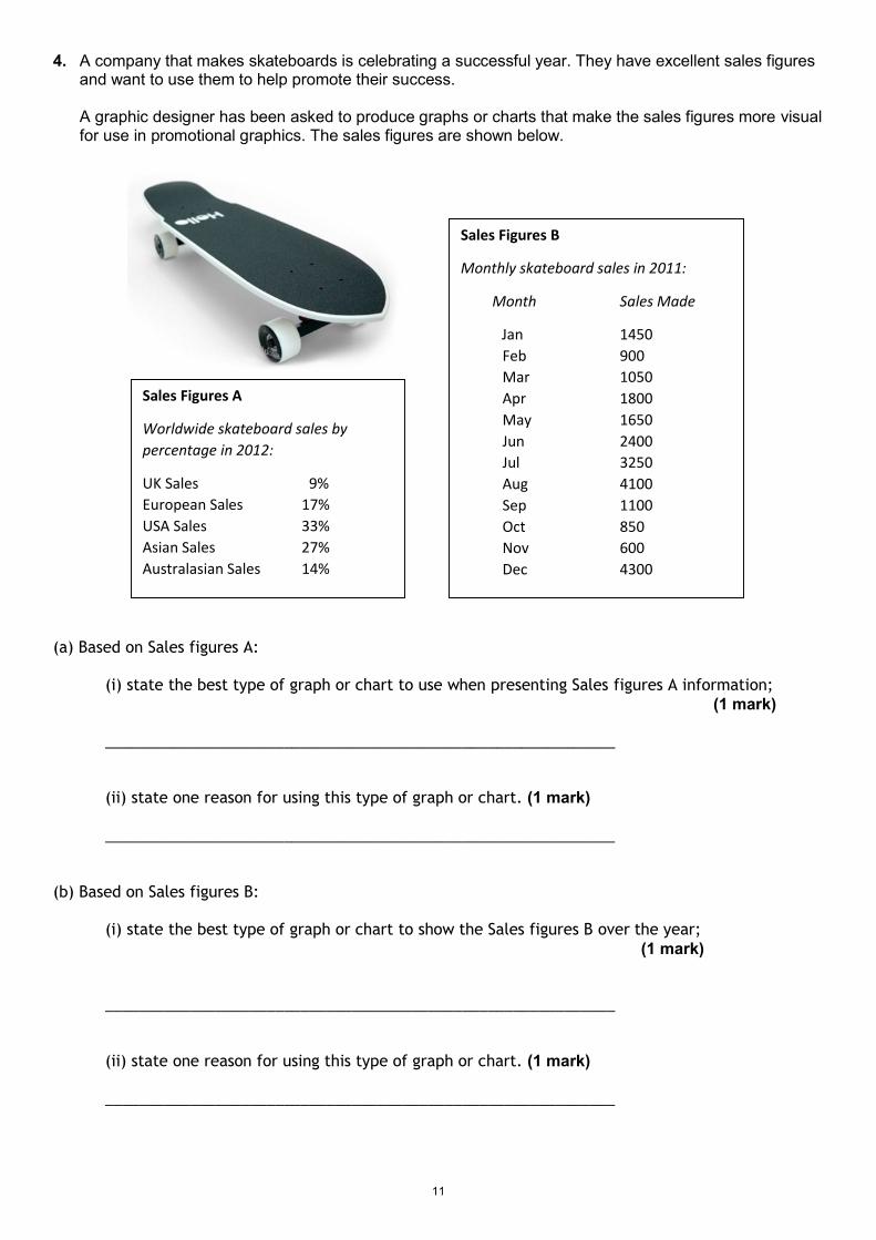
4. A company that makes skateboards is celebrating a successful year. They have excellent sales figuresand want to use them to help promote their success.
A graphic designer has been asked to produce graphs or charts that make the sales figures more visualfor use in promotional graphics. The sales figures are shown below.
(a) Based on Sales figures A:
(i) state the best type of graph or chart to use when presenting Sales figures A information;(1 mark)
____________________________________________________________
(ii) state one reason for using this type of graph or chart. (1 mark)
____________________________________________________________
(b) Based on Sales figures B:
(i) state the best type of graph or chart to show the Sales figures B over the year;(1 mark)
____________________________________________________________
(ii) state one reason for using this type of graph or chart. (1 mark)
____________________________________________________________
Sales Figures A
Worldwide skateboard sales bypercentage in 2012:
UK Sales 9%European Sales 17%USA Sales 33%Asian Sales 27%Australasian Sales 14%
Sales Figures B
Monthly skateboard sales in 2011:
Month Sales Made
Jan 1450Feb 900Mar 1050Apr 1800May 1650Jun 2400Jul 3250Aug 4100Sep 1100Oct 850Nov 600Dec 4300
11

5. (a) A floor plan with some electrical symbols is shown below:
(a) continued
(i) Identify, by placing an X in the box below the symbol, which symbol represents a light switch.(1 mark)
£ £ £
(ii) How many windows face east? (1 mark)
_________________________________________________________________
(b) All of the symbols shown above are stored in a CAD library.
(i) State one advantage of using a CAD library. (1 mark)
_________________________________________________________________
(ii) State one advantage of using symbols in graphic communication. (1 mark)
_________________________________________________________________
12

6. Orthographic CAD drawings for a mains water pipe elbow are shown below.
Water Mains Pipe Elbow Scale 1:4
(a) Identify, by placing an X in the box below, which pictorial view matches the pipe elbow in theorthographic production drawings above: (1 mark)
£ £ £ £ £
(b) Identify, by placing an X in the box below, which sectional view matches the pipe elbow in theorthographic production drawings above: (1 mark)
£ £ £ £
Z
13

6. (continued)
Dimensions are not normally added to orthographic assembly drawings.
(c) State the type of orthographic production drawings that will normally include dimensions. (1 mark)
____________________________________________________________________________
Sectional drawings are shown on the previous page, as part of Q6 (b)
(d) State one benefit of using a sectional drawing in relation to this pipe elbow. (1 mark)
_______________________________________________________________________________
(e) Explain what scale 1:4 means. (1 mark)
_______________________________________________________________________________
(f) State the name of the symbol shown at Z. (1 mark)
_______________________________________________________________________________
(g) Describe the purpose of this symbol. (1 mark)
_______________________________________________________________________________
_______________________________________________________________________________
(h) State where on orthographic drawings, the information “All sizes in mm” would be found. (1 mark)
_______________________________________________________________________________
14

7. An exploded pictorial view and a parts list for a small flat pack stool are shown below:
ITEM NO. PART NUMBER NAME / DIMENSIONING MATERIAL NO. REQUIRED1 111631 A-Frame 500 x 300 x 40mm Pine 22 103404 Top Bar 200 x 40 x 20mm Pine 23 103405 Centre Bar 220 x 40 20mm Pine 14 102600 Stool Top 350 x 350 x 20mm Pine 15 102646 Angled Bracket Steel 46 101350 Bolt – M8 x 60mm Steel 27 100159 Dowel Ø8 x 20mm Ramin 14
(a) State the material of part 103404. (1mark)
_____________________________________________________________________________
(b) State the length of the Centre Bar. (1mark)
_____________________________________________________________________________
15

7. (continued)
(c) State how many Angled Brackets are required for the assembly. (1mark)
_____________________________________________________________________________
(d) State the diameter of part 101350. (1mark)
_____________________________________________________________________________
(e) State the part number for the A-Frame. (1mark)
_____________________________________________________________________________
(f) State how many 8mm dowels are required. (1mark)
_____________________________________________________________________________
16

8. A poster promoting “smartWATCH”, a new smart phone accessory for men, is shown on the facingpage.
The text and the images used in the poster are laid out in their original form at the top of the page.
The final poster layout, (bottom of the page), promotes the smart watch.
The original graphics and text were edited in a DTP package before being placed in the final layout.
(a) State the name of the DTP editing feature applied to each of the original items to get them ready foruse in the final layout.
Do not include “scaling or resizing” in your answer.Ensure you do not use the same answer twice.
(i) Photograph of the model—state one DTP edit. (1 mark)
Edit_____________________________________________________________________________
(ii) Product photo of smart watch —state one DTP edit. (1 mark)
Edit_____________________________________________________________________________
(iii) “smartWATCH” brand name—state one DTP edit. (1 mark)
Edit_____________________________________________________________________________
(iv) Background silhouette—state one DTP edit (do not repeat a previous answer). (1 mark)
Edit_____________________________________________________________________________
(v) Slogan —state one DTP edit. (1 mark)
Edit_____________________________________________________________________________
(b) State one way in which the final layout of the slogan improves the promotional poster. (1 mark)
___________________________________________________________________________________
(c) When setting up the layout the designer used the following DTP features: Grid and Snap to grid.
State two ways in which the use of Grid and Snap to grid benefit the graphic designer. (2 marks)
_______________________________________________________________________________
_______________________________________________________________________________
_______________________________________________________________________________
17

8. (continued)
Text and images used for final layout:
Final layout:
[ END OF PRELIM PAPER ]18