nascio ea development tool-kit solution architecture …€¦ · · 2016-09-26strategy identified...
TRANSCRIPT
NASCIO EA Development Tool-Kit
Solution Architecture
Version 3.0
October 2004
NASCIO EA Tool-Kit Version 3.0 – Solution Architecture ii
TABLE OF CONTENTS
SOLUTION ARCHITECTURE ................................................................................................................... 1
Introduction.............................................................................................................................................. 1 Benefits ............................................................................................................................................... 3 Link to Implementation Planning ....................................................................................................... 4
Definitions................................................................................................................................................ 5 Roles ........................................................................................................................................................ 6 Solution Architecture Framework............................................................................................................ 7 Solution Set Structure .............................................................................................................................. 8
Solution Set Scope .............................................................................................................................. 8 Solution Set Requirements................................................................................................................ 10 Solution Set Design........................................................................................................................... 11
SOLUTION ARCHITECTURE DEVELOPMENT................................................................................... 13
Initiate Solution Architecture Documentation Process .......................................................................... 15 The Process Overview ...................................................................................................................... 15 The Process Detail ............................................................................................................................ 17
Conduct Solution Set Work Sessions..................................................................................................... 18 Process Overview.............................................................................................................................. 18 The Process Detail ............................................................................................................................ 21
Create/Update Solution Set Items .......................................................................................................... 23 Process Overview.............................................................................................................................. 23 Process Detail.................................................................................................................................... 26
Solution Set Scope Template ................................................................................................................. 28 Template Overview........................................................................................................................... 28 Template Detail................................................................................................................................. 31
Solution Set Requirements Template..................................................................................................... 34 Template Overview........................................................................................................................... 34 Template Detail................................................................................................................................. 43
Solution Set Design Template................................................................................................................ 46 Template Overview........................................................................................................................... 46 Template Detail................................................................................................................................. 49
Solution Set Vitality Review.................................................................................................................. 51 Process Overview.............................................................................................................................. 51 The Process Detail ............................................................................................................................ 54
SAMPLES .................................................................................................................................................. 56
Project: Child Support Payments to Other States .................................................................................. 56 Solution Set Scope ............................................................................................................................ 56

NASCIO EA Tool-Kit Version 3.0 – Solution Architecture iii
Child Support Payments to Other States (ACH) – Solution Set Scope ............................................ 59 Child Support Payments to Other States (ACH) – Solution Set Requirements ................................ 61 Child Support Payments to Other States (ACH) – Solution Set Design........................................... 64
A Solution Project: Enterprise GIS Clearinghouse............................................................................... 67 Enterprise GIS Clearinghouse – Solution Set Scope ........................................................................ 67 Enterprise GIS Clearinghouse and Portal – Solution Set Requirements........................................... 69 Enterprise GIS Clearinghouse – Solution Set Design....................................................................... 71
Project: e-Forms.................................................................................................................................... 73 e-Forms - Solution Set Scope............................................................................................................ 73 e-Forms – Solution Set Requirements............................................................................................... 75 e-Forms - Solution Set Design .......................................................................................................... 77
Sample Requirements/Design Specifications ........................................................................................ 78
SUMMARY................................................................................................................................................ 79
NASCIO EA Tool-Kit Version 3.0 – Solution Architecture 1
SOLUTION ARCHITECTURE
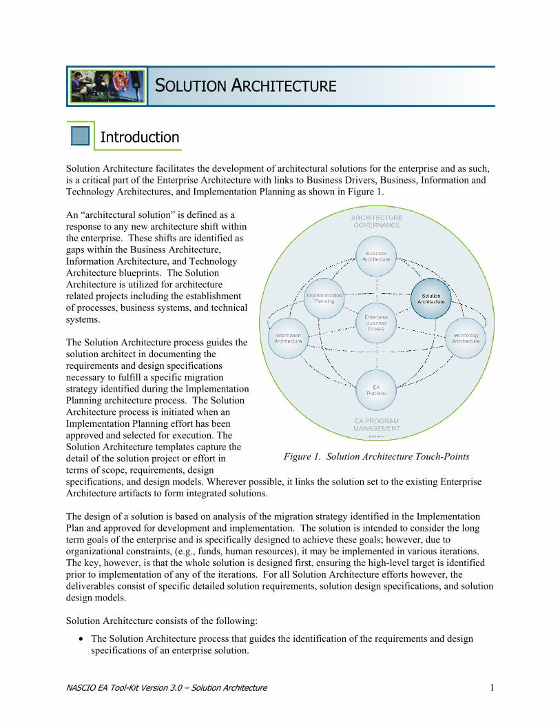
Introduction Solution Architecture facilitates the development of architectural solutions for the enterprise and as such, is a critical part of the Enterprise Architecture with links to Business Drivers, Business, Information and Technology Architectures, and Implementation Planning as shown in Figure 1. An “architectural solution” is defined as a response to any new architecture shift within the enterprise. These shifts are identified as gaps within the Business Architecture, Information Architecture, and Technology Architecture blueprints. The Solution Architecture is utilized for architecture related projects including the establishment of processes, business systems, and technical systems. The Solution Architecture process guides the solution architect in documenting the requirements and design specifications necessary to fulfill a specific migration strategy identified during the Implementation Planning architecture process. The Solution Architecture process is initiated when an Implementation Planning effort has been approved and selected for execution. The Solution Architecture templates capture the detail of the solution project or effort in terms of scope, requirements, design specifications, and design models. Wherever possible, it links the solution set to the existing Enterprise Architecture artifacts to form integrated solutions. The design of a solution is based on analysis of the migration strategy identified in the Implementation Plan and approved for development and implementation. The solution is intended to consider the long term goals of the enterprise and is specifically designed to achieve these goals; however, due to organizational constraints, (e.g., funds, human resources), it may be implemented in various iterations. The key, however, is that the whole solution is designed first, ensuring the high-level target is identified prior to implementation of any of the iterations. For all Solution Architecture efforts however, the deliverables consist of specific detailed solution requirements, solution design specifications, and solution design models. Solution Architecture consists of the following:
• The Solution Architecture process that guides the identification of the requirements and design specifications of an enterprise solution.
Figure 1. Solution Architecture Touch-Points
NASCIO EA Tool-Kit Version 3.0 – Solution Architecture 2
• Solution Architecture templates that capture detail about the solution being created. The specific templates are: − Solution Set Scope – Describes the overall solution and links the solution to the Implementation
Plan; defines a conceptual model of the solution. − Solution Set Requirements – Lists the various solution set requirements based on specific
solution set types, views, and categories. These views examine the required functionality necessary to fulfill the Business Architecture, Information Architecture, and Technology Architecture requirements.
− Solution Set Design - Lists the various solution set design specifications based on specific set types, views, and categories. In addition, they provide the information to assess the solution impacts to the current environment in the areas of capacity, training, business continuity, etc.
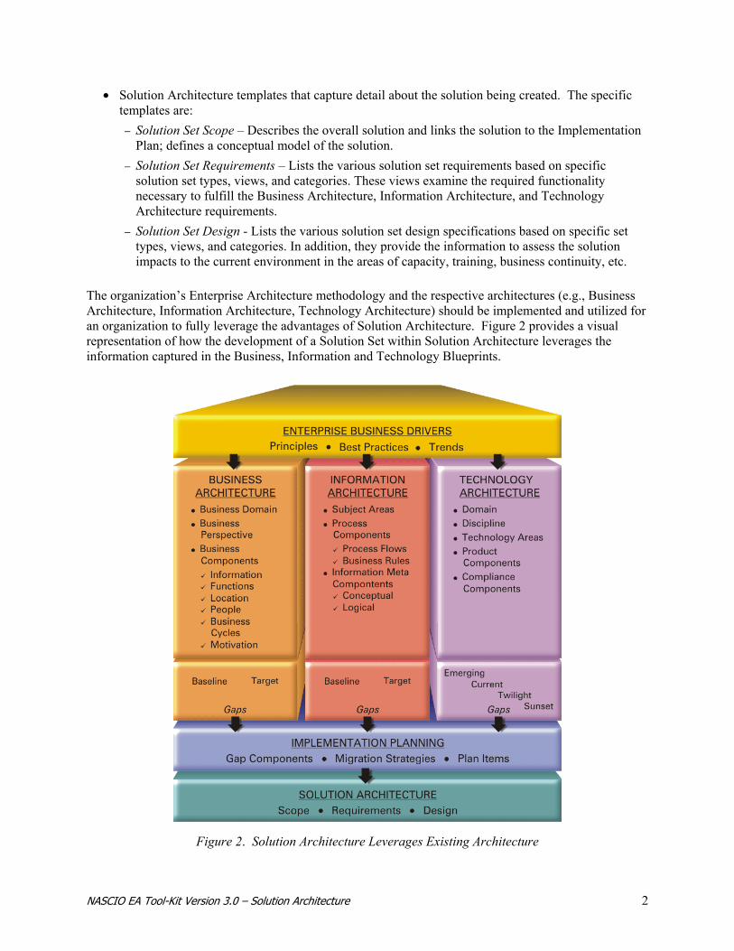
The organization’s Enterprise Architecture methodology and the respective architectures (e.g., Business Architecture, Information Architecture, Technology Architecture) should be implemented and utilized for an organization to fully leverage the advantages of Solution Architecture. Figure 2 provides a visual representation of how the development of a Solution Set within Solution Architecture leverages the information captured in the Business, Information and Technology Blueprints.
Figure 2. Solution Architecture Leverages Existing Architecture

NASCIO EA Tool-Kit Version 3.0 – Solution Architecture 3
In addition to the architectural blueprints developed within these architectures, further benefits of Solution Architecture can be realized by referencing and building the solution around the following organizational constructs:
• The Enterprise Application Portfolio – Current inventory of applications and components, complete with relationships to supported business processes, interfacing systems, supplied/required information and infrastructure configurations. The Application Portfolio can be very detailed and maintained by an extensive portfolio management system, or it may be a simple list of the business applications in use within the organization. The more detailed the inventory, the better able to enterprise is to access current capabilities and future requirements.
• Design Models – Pre-existing formats used to guide the development of the Solution Architecture artifacts (e.g., logical design). These models are typically graphical in nature and show the relationships among the elements of the solution. Models, which provide simplified abstract representations of complex information, are used for communication, analyzing, testing, simulating, or exploring options. The various types of models (e.g., Business Process Models, Software Models) approved for usage by the organization are created within the Business, Information and/or Technology Architectures and are leveraged when building a solution design. An example of a model used to document business processes is the SIPOC model. The SIPOC model depicts a business process in terms of the S (Supplier), I (Input), P (Process), O (Output), and C (Consumer). The unpopulated model, or template, is contained within the Information Architecture. The model is used to develop the unique solution model during the Solution Architecture process.
• Design Patterns – Design Patterns are pre-existing configurations that identify a collection of architecture components and describe commonly recurring structures, systems, and processes within the enterprise. A pattern provides the bundling of a set of commonly recurring subsystems or components necessary to solve a general solution design. In addition, a pattern specifies sub-system or component characteristics and responsibilities, and includes rules and guidelines for organizing these relationships. Patterns can help expedite the delivery of a solution because they can be used to quickly identify groups of components required to build a system or solution. The various patterns prescribed for usage by the organization are created as part of the Business, Information and/or Technology Architecture processes, and are leveraged when building a solution design. These patterns are bundled views of the current and future architecture processes that exist within the architecture inventory. A typical list of patterns would include design patterns (such as object oriented software design), analysis patterns (such as recurring and reusable analysis models), infrastructure patterns (such as N-tier), organizational patterns (such as structure of organizations and projects) and process patterns (which are used for process design).
Solution Architecture provides guidance for what is to be developed and how it fits into the overall enterprise. However, for IT related solutions, it does not recommend the specifics of the development life cycle (e.g., requirements gathering, analysis, usage of design tools, testing, or implementation tasks). These documents are characteristically a part of the organization’s Technology Architecture methodologies.
The quality of Solution Architecture is no better than the quality of the Business Architecture, Information Architecture, and the Technology Architecture. The focus is not on enabling a single solution, but on identifying and enabling the optimal portfolio of enterprise solutions. Solution Architecture provides the following benefits to a governmental organization:
BENEFITS

NASCIO EA Tool-Kit Version 3.0 – Solution Architecture 4
• Ensures that information and services are served holistically across the organization • Identifies the solution patterns for the future state of the solutions architecture • Is a quick start for project leaders, managers, and architects when developing solutions and services
The following are considered critical success factors to achieving enterprise wide, integrated solutions:
• Proven success in the development of Business Architecture and Information Architecture • A holistic view of the enterprise • Strong linkage among, and definition of, the business change requirements • Business information requirements • Information technology requirements that describe the business solutions requirements to support
enterprise business strategies To implement a Solution Architecture to the fullest extent, the following “Best Practices” apply:
• A solution should be architected with the life-cycle of the solution in mind • Converge on a solution: Use scenario planning models to identify and access alternatives • Personalization for ease of access • All solutions to be “highly granular” and “loosely coupled” • Solutions are built from existing Enterprise Architecture (EA) components • Capture EA information, design models and solution sets in a robust EA repository to maximize the
potential for reuse • All solutions must conform to common enterprise-wide IT interoperability standards • Establish and manage solution requirements
Implementation Planning is the process that consolidates all the gaps and migration strategies for the purposes of assessing the potential architecture related work load needing to be addressed by the enterprise. The following information is provided to introduce the concept of Implementation Planning and remind the reader of the background information that is available to the Solution Architect upon initiation of the solution documentation process. The Solution Architecture process is initiated for a specific solution effort contained in the Implementation Plan and proceeds after receiving approval. This approval, which occurs during the Implementation Planning architecture process, is based on several key factors including the effort’s prioritization, cost/benefit analysis, enterprise architecture fit, commitment of resources, etc. The Solution Architecture process also leverages the information developed during the Implementation Planning process. Information created during the Implementation Planning process and used during the Solution Architecture process includes the gaps identified as related to the solution effort and migration strategy, the high-level requirements, and the conceptual model that was created for this specific migration strategy.
LINK TO IMPLEMENTATION PLANNING

NASCIO EA Tool-Kit Version 3.0 – Solution Architecture 5
For each project or effort that is approved to move into the Solution Architecture process, a conceptual model is required. The conceptual model:
• Should be in enough detail as to help determine the organizational areas that need to be interviewed to capture the Solution Set business requirements
• Will be used to validate the solution intent with the project sponsor • Defines the business problem and presents a high level description of the proposed solution in
terms of a set of integrated ideas and concepts about what it should do, how it should behave, and what it should look like – in terms that are understandable to the project sponsor
Definitions When discussing Solution Architecture and related topics, the terminology varies, including a variety of terms with the same or similar meanings, as well as varied meanings for the same term. To minimize any confusion in terminology, a glossary, which provides definitions of terms used throughout the Tool-Kit is provided in Appendix A of the NASCIO Enterprise Architecture Tool-Kit document. A brief list of the terms and definitions used within this Solutions Architecture section are provided here:
• Architectural Patterns: The expression of a fundamental structural organization or schema for a system or solution. It provides a set of predefined subsystems, specifies their responsibilities, and includes rules and guidelines for organizing the relationships between them.
• Architecture Blueprint: The dynamic detail of the business, information or technology captured utilizing standardized, structured processes and templates (framework).
• Architecture Framework: The combination of structured processes, templates and governance that facilitate the documentation of the architecture in a systematic manner.
• Baseline: Current or “as is” state of the business environment, captured in a set of baseline business models.
• Business Architecture: The high-level representation of the business strategies, intentions, functions, processes, information, and assets (e.g., people, business applications, hardware) critical to providing services to citizens.
• Business Domain: A functional or topical subset of business operations integral to the enterprise operations.
• Business Portfolio: The implemented baseline business environment (e.g., implemented business processes, strategies, data of the business organization).
• Conceptual Patterns: A pattern whose form is described by means of terms and concepts from a business, technology or application domain.
• Design Patterns: Structure that provides a scheme for refining the subsystems or components of a system, or the relationships between them. It describes commonly recurring structure of communicating components that solves a general design problem within a particular context.
• Information Architecture: The compilation of the business requirements of the enterprise. Includes the information, process entities, and integration that drive the business, as well as, rules for selecting, building and maintaining that information.
NASCIO EA Tool-Kit Version 3.0 – Solution Architecture 6
• Logical Information Model: Shows the main functional [information] components and their relationships within a system, independent of the technical detail of how the functionality is implemented.1
• Solutions Architecture: A process within the Enterprise Architecture that focuses on the development and implementation of the solution or service being created for the enterprise.
• Solutions Architecture Model: The graphical representation of concepts to portray a desired future state, as well as an undesirable current state. Used for communicating, analyzing, testing, simulating, or exploring options.
• Solution Pattern: The bundling of tested solutions or configurations commonly used together, which can be addressed as a whole.
• Solution Set: The combination of the scope, requirements, design specifications, and logical models that define the solution.
• Target: Desired future or “to be” state of the business environment, captured in a set of target business models.
• Technology Architecture: A disciplined approach to describing the current and future structure and inter-relationships of the enterprise’s technologies in order to maximize value in those technologies.
• Template: The empty form, provided as a guide for details of the architecture to be documented. Ultimately, the content captured utilizing architecture templates is referred to collectively as the Blueprint and resides in the architecture repository.
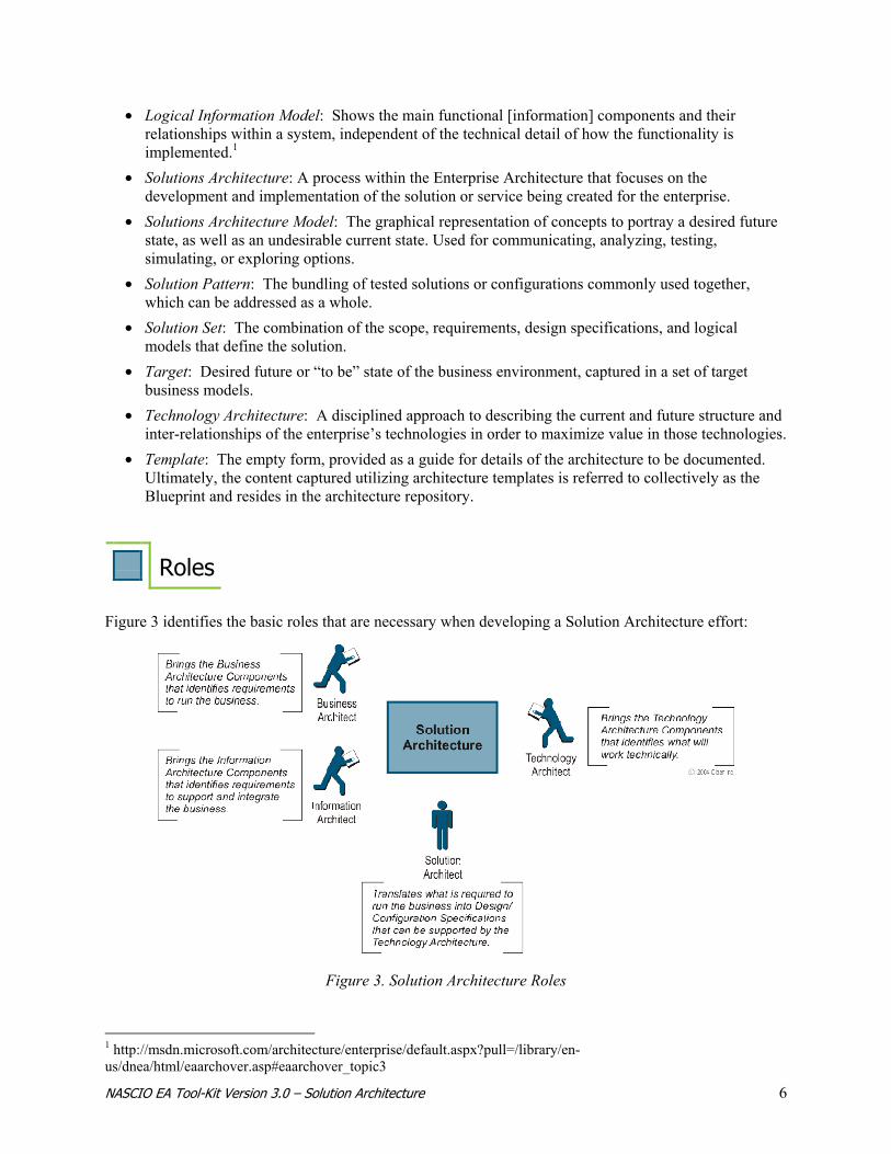
Roles Figure 3 identifies the basic roles that are necessary when developing a Solution Architecture effort:
1 http://msdn.microsoft.com/architecture/enterprise/default.aspx?pull=/library/en-us/dnea/html/eaarchover.asp#eaarchover_topic3
Figure 3. Solution Architecture Roles

NASCIO EA Tool-Kit Version 3.0 – Solution Architecture 7
Business Architect – Provides input concerning the elements necessary to run the business. This individual, or team, has a complete understanding of the artifacts and blueprints within the Business Architecture.
Information Architect – Provides input concerning the elements necessary to support and integrate the business and the key business information. This individual, or team, has a complete understanding of the artifacts and blueprints within the Information Architecture.
Technology Architect – Provides input concerning what infrastructure is required to support the application, infrastructure, or service being developed. This individual, or team, has a complete understanding of the artifacts, blueprints, configurations, and services within the Technology Architecture.
Solutions Architect – Translates the above elements into design and/or configuration specifications that can be supported by the Technology Architecture. This individual, or team, is the primary architect for this effort and is responsible for completing and delivering the solution design or model.
Solution Architecture Framework The Solution Architecture framework is a combination of structured processes and templates that utilize existing architecture documents (such as business, information, and technology components as well as models and patterns) to design a desired business solution. The Solution Architecture framework, by allowing the development of a Solution Set, facilitates the rapid development and delivery of a solution in a systematic and well-disciplined manner. By leveraging the components of the existing architectures, the solution that is developed will augment and extend the enterprise architecture. The solution’s design identified within the Solution Architecture will enable the organization to accurately determine the impacts to all resources (e.g., dollars, people, systems). This ensures that the solution leverages the target architectural components and enhances the Enterprise Architecture, thereby mitigating the possibility of undesirable architectural components. Designing the solution as prescribed in the Solution Architecture framework enables the identification of all architectural touch points, ensures involvement from architecture subject matter experts, and enables the implementation of specific items identified on the Implementation Plan. In addition, it completes the architecture loop by initiating the vitality of the Business, Information, and Technology Architecture artifacts affected by the modified or newly developed solution set. The effective use of a Solution Architecture framework provides a standardized approach when identifying requirements and design specifications for enterprise solutions by means of:
• Solution Set structure • Structured processes for documenting, developing, and implementing the solution set • Templates for capturing the solution set scope, requirements, and design specifications
The standardized approach leveraged by the Solution Architecture framework promotes a broader understanding of the enterprise and facilitates the integration and interoperability of solutions.

NASCIO EA Tool-Kit Version 3.0 – Solution Architecture 8
Solution Set Structure A Solution Set refers to the dynamic detail for a specified solution effort captured using the structured processes, and templates. This Solution Set provides the details of the Solution Set requirements and design specifications. Unlike the Business, Information, and Technology Architectures, the Solution Architecture does not contain baseline or target information. Rather, it provides the process and structure to enable the development of a solution or a tightly coupled series of solutions. The combination of the scope, requirements, design specifications, and logical models that define the solution is referred to as a Solution Set. After the Solution Set is completed and implemented within the enterprise, the Solution Architecture documentation is used for historical purposes only. The information created as part of the Solution Set is updated within the appropriate Business Architecture, Information Architecture, and/or Technology Architecture blueprints once the solution set is implemented within the enterprise. The Solution Set is comprised of the Solution Set Scope, the Solution Set Requirements, and the Solution Set Design. The Solution Set contains the information necessary to implement the direction of the enterprise from business, information, and technology perspectives. Figure 4 provides a pictorial view of the relationship between the Solution Set elements. The graphic displays these pieces working together to ensure the complete documentation of the solution set that forms the high-level design of the complete solution effort.
The Solution Set Scope contains various details about the Solution Architecture effort being undertaken within the enterprise. It is unique in nature and typically addresses one effort contained on the Implementation Plan. A Solution Set Scope template should be filled out for each Solution Architecture effort undertaken. The Solution Set Scope describes the solution in enough detail to aid in determining the overall scope of the effort. An initial high-level scope should have been captured when documenting the migration strategy for the associated gap component. The Solution Set Scope can be used by the Solution Architect to re-affirm the migration strategy and to document additional information about the proposed effort. If there are numerous migration strategies associated with the original Business Architecture, Information Architecture, or Technology Architecture gap component, each migration strategy would require a unique Solution Set Scope template. When populated, this template provides the necessary background information for the effort. It contains a link to the proposed solution’s conceptual model contained in the Implementation Plan. In addition, it links to the reference material that will be needed when completing the rest of the solution set requirements and design specifications. The information referenced will include such items as:
SOLUTION SET SCOPE
Figure 4. Solution Set Structure
NASCIO EA Tool-Kit Version 3.0 – Solution Architecture 9
• The priority of the effort • The associated business case • A risk assessment • The gap components that contained information on the business needs • The potential migration strategies • Associated Architecture Components • The high-level scope and description of the effort
The Solution Set Scope template also references the original architecture blueprints that identified the future state that the solution set seeks to implement. These are the blueprints created during the Business, Information, and Technology Architecture efforts. With the above information available, the Solution Architect can then fully populate the Solution Set Scope Template. The scope of the effort is detailed at a lower level, and the areas supporting the identification of the solution requirements are identified and documented. The Solution Set Scope template is also used to identify the type of solution being designed. A description of the typical Solution Set types include:
• Business Solution – The solution will implement a business process, organizational, or other type of business solution. This may include new business processes, organizational structures, methodologies, etc.
• Application Solution – The solution involves the purchase and/or development of a traditional business system application.
• IT Infrastructure Solution – The solution involves the purchase and/or design of IT infrastructure components. This includes traditional IT infrastructure such as Networks, Platforms, etc. as well as the infrastructure to support the application development environment (e.g. Websphere, .NET, Java).
Once the solution type has been identified, the solution requirements and design specifications can be addressed. It may be possible for a Solution Set to consist of a business solution, an application solution, an IT infrastructure solution, or a mix of these types. This list is an example of the most common solution types. Organizations may identify additional solution types depending upon the needs of the organization. The Solution Set templates provided in this Tool-Kit are designed to accommodate the documentation of multiple solution types within a single effort. Multiple types can be indicated in the Solution Set Scope template and the Solution Set Requirements and Design templates can be customized to address multiple solution types within a Solution Set by replicating the sections as needed. Depending upon the intent, size, and complexity of the solution, the actual solution types will vary. For example, if the solution is small and will implement only business process changes, the only solution type that may need to be completed is that of “Business”. However, if the solution is intended to encompass the implementation of a major new business system, it is highly likely that the Business, Application, and Infrastructure types will need to be completed to capture all the requirements and design considerations for the whole solution. The types are referenced and utilized when documenting the solution requirements, the logical model, and the design specifications. However, due to the specific organizational processes and culture, the templates

NASCIO EA Tool-Kit Version 3.0 – Solution Architecture 10
may be leveraged as deemed necessary to support specific organizational needs. It is up to the discretion of the Documenters to decide the best approach for their organization.
The first part of designing the solution set involves gathering the functional requirements. These requirements are extrapolated from various Business, Information, and Technology Architecture components and from information previously identified in the Gap and Migration Strategies. During creation of the desired solution set type, the information is refreshed for timeliness and accuracy by working with the business users and sponsors of the project or effort. The requirements must be in sufficient detail to enable the development of the Solution Set Logical Model and the design specifications which will occur in subsequent phases of the process. REQUIREMENTS VIEWS To assist with the collecting of information, the Solution Set Type section on the template is further divided into various “views”. The use of views helps the Solution Architect ensure all of the information for the solution has been collected, based on the various aspects or discrete focuses of the solution. The typical views that may be included when developing requirements include:
• Business View – Pertains to how business requirements will be addressed in the solution. This includes such requirements as financial, strategic planning, business cycles, organizational, business drivers, logistical, as well as policy and procedures. This view typically aligns with the information contained within the Business Architecture blueprint.
• Security View – Pertains to how security requirements will be addressed in the solution. These requirements may be in terms of physical security, human resource security, information security, and IT security. They are grouped into security categories known as management, operational, and technical security controls.
• Information View - Pertains to how information requirements will be addressed in the solution. This typically includes such requirements as process flows, information ownership, metadata, spatial data, data architecture, data standards, document management, knowledge management, and content management.
• Application View – Pertains to how application system requirements and design considerations will be addressed in the solution. This typically includes such categories as application functionality, application structure, performance, reliability, availability, and maintainability.
• Usability View - Pertains to how application system usability requirements and design considerations will be addressed in the solution. This typically includes the graphical user interface (GUI), any dialogs and queries that need to be performed by the application, any input forms to be developed, any user reports that the system needs to produce, and accessibility needs.
• Infrastructure View - Pertains to how IT infrastructure requirements and design considerations will be addressed in the solution and typically includes such categories as hardware, software, voice, middleware, and databases.
• Integration View - Pertains to how the results of the Solution Set will integrate with components of the existing environment. This includes such integration requirements as process, application, infrastructure, and those requirements external to the organization. It is also concerned with the impacts to the current environment in the form of training, resources, capacity, performance, and bandwidth. The integration requirements addressed in the solution may be categorized as training, capacity, performance, and managerial.
SOLUTION SET REQUIREMENTS

NASCIO EA Tool-Kit Version 3.0 – Solution Architecture 11
CATEGORIES The Solution Set Requirements template also leverages the usage of ‘categories’ as a mechanism for classifying requirement sub-types. These category lists are for illustration purposes only and help to further identify the areas within the enterprise architecture that the Solution Architect will need to examine for potential component reuse. In addition, it will also help to identify those areas of responsibility for coordinating changes or solution dependencies. For a list of categories as defined on the Solution Set Requirements templates, please reference the specific template section of the manual. Your organization may or may not leverage the use of categories. If they do, they may be similar to the categories discussed in the Requirements templates section; however, it is unlikely that they will perfectly match. The Solution Architect may choose to leverage the use of categories. If this is indeed the case, they may customize these categories to fit their environment and organizational standards.
Upon establishing all the necessary Solution Set requirements, the Solution Architect’s attention turns to developing the Solution Set designs and logical models via the design process. The Solution Set Design template assists in the development of these solution set designs. The Solution Set Design template is used to capture the various design specifications, dependencies, and other organizational and environmental impacts. It is linked to existing enterprise architecture artifacts, models, and patterns. If there are no existing artifacts that substantiate the logical model it is quite possible that architecture gaps may result. If gaps are identified the solution set may be rendered architecturally non-compliant and an architectural review should be executed to determine if the solution should move forward. Architecture gaps identified at this point become dependencies of the Solution Set and, if they are not resolved, it is quite possible for the effort to be put on hold or terminated. The actual design specifications documented in the Solution Set Design are at the lowest level of documentation. These specifications address the specific requirements captured when the solutions architect completed the Solution Set Requirements. Once the specifications are captured in narrative, they can be consolidated and represented in the form of logical design models. Logical models will later be used to produce physical design models. The development of the physical design models is beyond the scope of the Solution Architecture process. Development of the physical models for the solution is typically completed within the standard SDLC or business process development methodologies within the organization. LOGICAL MODELS After the design specifications have been documented and the appropriate EA components for fulfilling the design specifications have been identified, the logical model can be developed. A logical model is utilized for both business and technical models. For proposed business solutions a process model is created. If the solution being presented is an IT solution then a logical architecture model is developed. It is quite possible for the Solutions Architect to create multiple logical architecture models depending upon the complexity and scope of the solution set. For example, the Solution Architect may propose process changes to a manual effort to solve a specific business need as well as an automated solution involving the development of a new IT system.
SOLUTION SET DESIGN
NASCIO EA Tool-Kit Version 3.0 – Solution Architecture 12
This logical model is used to:
• Validate and communicate the view of the proposed solution set to the business community and the project sponsor
• Determine the feasibility of the solution (e.g., technical, economic, operational, managerial, organizational)
• Show how the system will satisfy the user requirements • Reflect underlying business rules and activities rather than physical constraints and systems • Depict WHAT the solution will encompass, not HOW it will be accomplished • Capture the most critical and essential information in a fairly quick and concise manner
The logical model is captured in the form of a visual depiction of the solution with simple narrative about its included components. After all the requirements are documented, the design specifications are identified, and the logical model is complete, the Cost/Benefit analysis and initial Project Plan should be augmented to include the additional information captured during this process. The Solution Set Design activity concludes with a decision whether to pursue the desired solution. If there are multiple solutions presented, a selection is made on which solution is preferred and the design portion of the solution begins.

NASCIO EA Tool-Kit Version 3.0 – Solution Architecture 13
SOLUTION ARCHITECTURE DEVELOPMENT
The process of developing the Solution Architecture begins with initiating the Solution Architecture Documentation Process. This documentation process enables the architecture teams to develop the Solution Architecture Framework and to capture, analyze, and document requirements and design details about a specific project or effort. The work flow moves through the many layers of the process models and its sub-processes. Figure 5 provides a graphical representation of the high-level workflow path for the architecture team as they move through the processes and sub-processes of the Solution Architecture Documentation Process.
The Solution Architecture Documentation Process encompasses two major development phases: the creation of the framework and the development of a Solution Set, utilizing the structured processes and templates defined. Once the framework is established and approved, it remains constant until the Solution Architecture vitality process is invoked. The development of a Solution Set, however, is executed each time an approved project is selected for execution from the Implementation Plan. During the Solution Architecture Documentation Process for the Solution Set, details for a specifically selected solution are captured. This detail includes the scope of the particular project or effort, the functional and technical requirements, the design specifications, and lastly, the logical models that graphically depict the proposed solution. The Documenters develop the Solution Set by interviewing various Subject Matter Experts regarding the solution specifics. These explicit details of the solution are captured in the Solution Set. The Solution Architecture Documentation Process describes the systematic process for developing and maintaining the Solution Architecture Framework and various Solution Sets. The Solution Architecture Documentation Process consists of several sub-processes, including:
• Initiate Solution Architecture Documentation Process • Conduct Solution Architecture Work Sessions • Create/Update Solution Set Items
Figure 5. Solution Architecture Development Work Flow

NASCIO EA Tool-Kit Version 3.0 – Solution Architecture 14
• Solution Set Vitality Review The structure for each sub-process of this Solution Architecture Documentation Process follows the same format:
• Introductory material (where applicable) • Process model • Narrative description of the process • Template for capturing Solution Set detail (where applicable) • Narrative description of the detail to be captured utilizing the template
NASCIO EA Tool-Kit Version 3.0 – Solution Architecture 15
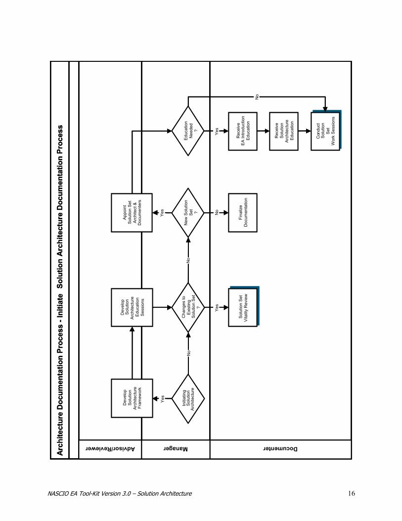
Initiate Solution Architecture Documentation Process
The Initiate Solution Architecture Documentation Process presented here is similar to the generic process model provided in the Architecture Governance Section of the Tool-Kit. This model and narrative provides the initial process steps that are specific to the Solution Architecture. The Solution Architecture Documentation Process can be triggered by the following processes/activities:
• Initiating Solution Architecture (SA) • Architecture Framework Vitality Review • Solution Set Vitality Review • New Solution Set
During the initiation of the Solution Architecture Documentation Process, the Solution Architecture Framework is developed. In this Tool-Kit, the term Architecture Framework refers to the combination of the structural elements of the architecture, including the structure of the templates and the structured processes for documenting, reviewing, communicating, implementing, and maintaining the Architecture Framework. Each governmental organization should develop a Solution Architecture Framework based on their individual circumstances and build the unique Solution Set team with the appropriate blending of business and technical Subject Matter Experts. The NASCIO Tool-Kit is designed to provide a jumpstart for organizations as they develop their architectures, not to provide a methodology. The Framework elements provided in this Tool-Kit represent a sampling of the structural elements an organization should consider as they build their Solution Architecture and is by no means exhaustive, nor is it intended to be prescriptive. There are many methods for designing solutions. Regardless of the one selected, the structure for capturing Solution Set detail should be consistent and concise to ensure uniform documentation and communication across the enterprise.
THE PROCESS OVERVIEW
NASCIO EA Tool-Kit Version 3.0 – Solution Architecture 16
Arc
hite
ctur
e D
ocum
enta
tion
Proc
ess
-Ini
tiate
Solu
tion
Arc
hite
ctur
e D
ocum
enta
tion
Proc
ess
Advisor/Reviewer DocumenterManager
No
Yes
Yes
Yes
Dev
elop
Sol
utio
nAr
chite
ctur
eFr
amew
ork
Dev
elop
Sol
utio
nAr
chite
ctur
eE
duca
tion
Ses
sion
s
Con
duct
Sol
utio
nS
etW
ork
Ses
sion
s
Rec
eive
EA
Intro
duct
ion
Educ
atio
n
Educ
atio
nN
eede
d?
Initi
atin
gS
olut
ion
Arc
hite
ctur
e
Rec
eive
Sol
utio
nA
rchi
tect
ure
Educ
atio
n
App
oint
Solu
tion
Set
Arch
itect
&D
ocum
ente
rs
No
No
Cha
nges
toE
xist
ing
Sol
utio
n S
et?
Yes
Sol
utio
n S
etV
italit
y R
evie
w
New
Sol
utio
nS
et ?
Fina
lize
Doc
umen
tatio
n
No
Arc
hite
ctur
e D
ocum
enta
tion
Proc
ess
-Ini
tiate
Solu
tion
Arc
hite
ctur
e D
ocum
enta
tion
Proc
ess
Advisor/Reviewer DocumenterManager
No
Yes
Yes
Yes
Dev
elop
Sol
utio
nAr
chite
ctur
eFr
amew
ork
Dev
elop
Sol
utio
nAr
chite
ctur
eE
duca
tion
Ses
sion
s
Con
duct
Sol
utio
nS
etW
ork
Ses
sion
s
Rec
eive
EA
Intro
duct
ion
Educ
atio
n
Educ
atio
nN
eede
d?
Initi
atin
gS
olut
ion
Arc
hite
ctur
e
Rec
eive
Sol
utio
nA
rchi
tect
ure
Educ
atio
n
App
oint
Solu
tion
Set
Arch
itect
&D
ocum
ente
rs
No
No
Cha
nges
toE
xist
ing
Sol
utio
n S
et?
Yes
Sol
utio
n S
etV
italit
y R
evie
w
New
Sol
utio
nS
et ?
Fina
lize
Doc
umen
tatio
n
No

NASCIO EA Tool-Kit Version 3.0 – Solution Architecture 17
Develop Solution Architecture Framework – By using the Solution Architecture Framework, the Solution Set detail is captured and the Solution Set is created. The NASCIO Solution Architecture Framework provides the structure, processes and templates necessary for capturing specific Solution Set information. An enterprise may decide to use the framework described in the NASCIO Tool-Kit or may choose other processes, templates, and governance structure. Developing the processes and templates for capturing pertinent architecture detail, as well as defining and documenting the governance structure to support the architecture activity, is a step that is critical when initiating any of the architectures (e.g. Business, Information, Technology, and/or Solution Architecture). Each enterprise must decide upon the methodology that best suits their organization. The best methodology for an organization is one that addresses the resource and time constraints of that enterprise. It is best to consider the use of a repository or automated tool for the capture and storage of the architecture documentation. The use and maintenance of the Enterprise Architecture is greatly simplified when the information and models are readily available to all stakeholders. There is a large amount of information collected and documented within an EA with many interrelations among the various EA components. It is best if all the EA information, design models and solution sets are placed in a robust EA repository to maximize the potential for reuse. Develop Solution Architecture Education Sessions – The Solution Architecture Education Sessions provide a high-level overview of the Enterprise Architecture Program and prepare the Solution Set Documenters for their role in the Solution Architecture effort. Developers of education materials should consider inclusion of the following materials:
• Purpose • Presenters • Intended audience • Session structure • Prerequisites • Syllabus • Objectives • Class materials for both instructors and attendees
Finalize Documentation – The Solution Architecture educational materials should be finalized and stored with the other Enterprise Architecture training materials. Solution Set Vitality Review – If the Solution Set is being modified due to changes in scope, requirements, or design options, the various Solution Set items should be updated. In addition, if changes have occurred in Business, Information, or Technology Architecture blueprints that are referenced in a particular Solution Set, the Solution Set should be reviewed carefully to assess potential impacts. The process model and details pertaining to updating the Solution Set are presented in a separate process. (See Solution Set Vitality Review). Appoint Solution Set Architect & Documenters – The Solution Set Architect and Solution Set Documenters are appointed from subject matter experts familiar with the business and technical views of the enterprise. The team is comprised of business analysts who have expertise in the various aspects of the specific business area needing the solution. They are responsible for steering, shaping, and developing the
THE PROCESS DETAIL

NASCIO EA Tool-Kit Version 3.0 – Solution Architecture 18
scope and requirements of the solution set. If the Solution Set encompasses the design of a business application system or an IT infrastructure component, then it should also include the various technical subject matter experts that can adequately represent the identified technical area. The team should also include a Solutions Architect who is knowledgeable about the various solutions development processes and methodologies. It is the Solution Architect’s responsibility to ensure that the solution set is designed to:
• Meet the business need • Leverage the Business, Information, and Technology Architecture blueprints previously created in
the Enterprise The educational sessions described below are progressive in nature. The sessions will be conducted after the architecture team is identified: Receive EA Introduction Education – Documenters should receive initial training that covers the overview of enterprise architecture and architecture governance. Receive Solution Architecture Education – After receiving initial enterprise architecture training, the Documenters will receive specialized instruction addressing the Solution Architecture documentation templates and Solution Architecture documentation processes to be used to document a Solution Set. If the Documenters and Solution Architect are expected to start work on the development of a specific Solution following the delivery of the education, the documentation used during the session should include specific project detail found in the associated Implementation Planning, Gaps, and Migration Strategies items. Conduct Solution Set Work Sessions – Applying the knowledge gained in the two sessions, the Solution Architect and Documenters will begin development of the Solution Set. The detail of the Work Sessions is presented in a separate process. (See Conduct Solution Architecture Work Sessions).
Conduct Solution Set Work Sessions
The Solution Set Work Sessions are intended to produce the documentation that populates the Solution Set. The Solution Architecture is best documented by stakeholders involved in setting the scope, developing the requirements, and designing the solution. This will include various business and technical subject matter experts as well as those individuals who assisted in the development of the Implementation Plan item that identified the Solution Set project or effort. Ongoing Documenter meetings with the appropriate mix of business and technical Subject Matter Experts are required to document the specific solution set. The first session will include:
• Defining roles and responsibilities • Reviewing Solution Set documentation requirements • Determining expectation of follow-on meetings
PROCESS OVERVIEW

NASCIO EA Tool-Kit Version 3.0 – Solution Architecture 19
After the first meeting, on-going working sessions are triggered from Architecture Lifecycle Processes including:
• The need to complete the Solution Set documentation • Solution Set Vitality Process
The creation of the Solution Set provides the architectural design to solve a specific business need. Analyzing the various components of the Solution Set facilitates the process of articulating a design that can be readily developed and implemented. Individual requirements can be met by existing architectural components from the Business, Information, and Technology Architecture blueprints. The Solution Set Work Sessions typically continue until the Solution Set design is complete and approved by the stakeholder. Work sessions may start again if the Solution Set scope changes, if additional requirements are identified, or if the logical models are modified by the introduction of new architecture components or architecture patterns. In addition, the work session may commence again if the original project is halted and restarted at a later date. If this occurs, it will be necessary to re-validate the original scope, requirements and proposed design. The re-validation is required because of the dynamic nature of the Business, Information, and Technology Architecture blueprints. If items within the blueprints have been updated while the project was inactive, and the original assumptions and conclusions may no longer be valid.

NASCIO EA Tool-Kit Version 3.0 – Solution Architecture 20
Arc
hite
ctur
e D
ocum
enta
tion
Proc
ess
-Con
duct
Solu
tion
Arc
hite
ctur
e So
lutio
n Se
t Wor
k Se
ssio
ns
Solution Architect DocumenterReviewer /Advisor
Coo
rdin
ate
Sol
utio
n Se
tw
ithB
uild
Tea
m
Solu
tion
Set
Item
s Fi
naliz
ed?
Rev
iew
Sol
utio
n Se
tPa
cket
with
SM
Es
Rev
iew
with
Pro
ject
Stak
ehol
ders
Cre
ate/
Upd
ate
Sol
utio
n Se
tIte
ms
Com
pile
Sol
utio
n Se
tP
acke
t
Iden
tify
Solu
tion
Set
Typ
e
Rev
iew
Ass
ocia
ted
Impl
emen
tatio
nP
lan
Item
s
Det
erm
ine
Inte
rvie
wS
trate
gies
Iden
tify
Sub
ject
Mat
ter E
xper
ts
Yes
No
Rev
iew
for
Arc
hite
ctur
eC
ompl
ianc
e
Sum
mar
ize
Ent
erpr
ise
Arch
itect
ure
Blue
prin
t Usa
ge
Rev
iew
Sol
utio
n S
etIte
ms
Arc
hite
ctur
e D
ocum
enta
tion
Proc
ess
-Con
duct
Solu
tion
Arc
hite
ctur
e So
lutio
n Se
t Wor
k Se
ssio
ns
Solution Architect DocumenterReviewer /Advisor
Coo
rdin
ate
Sol
utio
n Se
tw
ithB
uild
Tea
m
Solu
tion
Set
Item
s Fi
naliz
ed?
Rev
iew
Sol
utio
n Se
tPa
cket
with
SM
Es
Rev
iew
with
Pro
ject
Stak
ehol
ders
Cre
ate/
Upd
ate
Sol
utio
n Se
tIte
ms
Com
pile
Sol
utio
n Se
tP
acke
t
Iden
tify
Solu
tion
Set
Typ
e
Rev
iew
Ass
ocia
ted
Impl
emen
tatio
nP
lan
Item
s
Det
erm
ine
Inte
rvie
wS
trate
gies
Iden
tify
Sub
ject
Mat
ter E
xper
ts
Yes
No
Rev
iew
for
Arc
hite
ctur
eC
ompl
ianc
e
Sum
mar
ize
Ent
erpr
ise
Arch
itect
ure
Blue
prin
t Usa
ge
Rev
iew
Sol
utio
n S
etIte
ms

NASCIO EA Tool-Kit Version 3.0 – Solution Architecture 21
Review Associated Implementation Planning Items – The project definition, scope, gap, and migration information developed as a part of Implementation Planning should be provided to the Documenters and the Solution Architect. The team will update the basic definitions as necessary and identify any additional information. During this process the scope of the solution is further developed and the Solution Set is defined in greater detail. The Documenters and Solution Architect are responsible for gathering all necessary information required to complete the Solution Set Scope template. Identify Solution Set Type – Based on the information obtained from a review of the Associated Implementation Plan Items, the Solution Architect and the Documenters will determine the type of Solution Set being designed. The solution may consist of one or multiple types of solutions. This may include the following:
• Business Solution – The solution will implement a business process improvement, organizational change, or other type of business solution.
• Application Solution – The solution will involve the purchase and/or development of an application system.
• IT Infrastructure Solution – The solution will involve the purchase and/or design of IT infrastructure components
The identification of the solution set type is necessary so that the team can identify the appropriate resources to provide Solution Set requirements, contribute to design specifications, and assist with the development of the Solution Set logical models. Identify Subject Matter Experts – Subject Matter Experts are experts in the area of the enterprise business and will assist in the identification of the scope of the Solution Set. These Subject Matter Experts will contribute to the development and detail of defining the Solution Set requirements, design specifications, and design models. Additionally, the Subject Matter Experts with the detailed knowledge of the various specifications are identified. If the Solution Set involves organizational processes and information, these individuals may be the same Subject Matter Experts as previously identified. If the Solution Set involves the creation of an IT business system or related IT infrastructure, the Subject Matter experts will be from areas specific to the IT solution area. This may include Subject Matter Experts knowledgeable in application development methodologies, tool, and development environments. It may also include experts knowledgeable in technology infrastructure areas such as security and networks. Determine Interview Strategies – Interview meeting topics should be determined in one of the first working sessions. Interview questions should be designed to streamline the interview process and get the most information in a minimum amount of time. In addition, it is sometimes helpful to hold the interviews in a location away from the interviewees primary work location. This will help focus discussions and avoid repeated work related interruptions. Approaches for determining interview strategies can be based on:
• The Solution Set views necessary to complete the design. These views are intended to help the solution architect collect all the information for the solution and are based on various aspects or discrete focuses of the solution. The specific types of views that may be included when developing requirements include:
THE PROCESS DETAIL
NASCIO EA Tool-Kit Version 3.0 – Solution Architecture 22
− Business View – Pertains to how business requirements will be addressed in the solution. This includes such requirements as financial, strategic planning, business cycles, organizational, business drivers, logistical, policy, and procedures. This view typically aligns with the information contained within the Business Architecture blueprints.
− Security View – Pertains to how security requirements will be addressed in the solution. These requirements may be in terms of physical security, human resource security, information security, and IT security. They are grouped into security categories known as management, operational, and technical security controls.
− Information View – Pertains to how information requirements will be addressed in the solution. This typically includes such requirements as process flows, information ownership, metadata, spatial data, data architecture, data standards, document management, knowledge management, and content management.
− Application View – Pertains to how application system requirements and design considerations will be addressed in the solution. This typically includes such categories as application functionality, application structure, performance, reliability, availability, and maintainability.
− Usability View – Pertains to how application system usability requirements and design considerations will be addressed in the solution. This typically includes the graphical user interface (GUI), any dialogs and queries that need to be performed by the application, any input forms that need to be developed, any user reports that the system needs to produce, and accessibility needs.
− Infrastructure View – Pertains to how IT infrastructure requirements and design considerations will be addressed in the solution and typically includes such categories as hardware, software, voice, middleware, and databases.
− Integration View – Pertains to how the results of the Solution Set will integrate with components of the existing environment. This includes such integration requirements as process, application, infrastructure, and those external to the organization. It is also concerned with the impacts to the current environment in the form of training, resources, capacity, performance, bandwidth, and so forth. The integration requirements addressed in the solution may be categorized as training, capacity, performance, and managerial.
• The functional requirements to be documented. This format captures the necessary Solution Set requirements that must be satisfied in order to meet the business need.
• Developing design specifications. • Determining other organizational and system impacts.
Create/Update Solution Set Items – At this point in the process interviews will be conducted and the Solution Set documentation will be undertaken. The Solution Set items include the Solution Set Scope, the Solution Set Requirements, and Solution Set Design. A separate process model and narrative for this sub-process will provide greater detail (See Create/Update Solution Set Items). Review Solution Set Items - The number and point of reviews should be determined for each Solution Set. For complex projects, it may be appropriate to have interim reviews at the completion of scope and again at the completion of the requirements. The Reviewers, who should include the project sponsor and designated representatives from the architecture community, can add valuable insight from an over-arching perspective. Compile Solution Set Packet – When the Solution Set design specifications, solution impacts, and design model(s) are complete, a summary should be compiled and the various pieces of the Solution Set
NASCIO EA Tool-Kit Version 3.0 – Solution Architecture 23
documentation should be submitted for review. A packet containing the completed Solution Set documentation will be compiled in preparation for formal review. This is typically reviewed by the project manager, all project Subject Matter Experts, the chief architect, and representatives from the impacted functional areas. Review Solution Set Packet with SMEs – The Solution Set Architect as well as the SMEs that contributed to the effort will verify the final contents of the Solution Set Packet and work with the Documenters to make modifications as necessary. This review provides the opportunity for those who participated in the definition of the requirements and/or design to see and provide feedback on the final product. Review for Architecture Compliance – The Solution Architect will review the Solution Set Packet with the various architecture representatives, ensuring that the Solution Set is in compliance with the documented architecture components:
• Business Architecture – Business Architecture Components • Information Architecture – Process and Information Meta Components. • Technology Architecture – Product and Compliance Components.
If inconsistencies are found, the Solution Architect will work with the Documenters to make modifications as necessary, to recompile the Solution Set Packet and to start the review process again. Review with Project Stakeholders – The Solution Architect will review the Solution Set Packet with the various stakeholders of the project (e.g., project sponsor) ensuring the Solution Set is designed to meet the original needs of the project. If for any reason the Solution Set does not meet the expectations of the stakeholders, the Solution Architect will work with the Documenters to make modifications as necessary, recompile the Solution Set Packet, and start the review process again. Coordinate Solution Set with Build Team – When the Solution Set is approved, it must be referred to the team responsible for executing the Business Development Process or the SDLC. All information obtained in the Solution Set (e.g., project scope, requirements, design specifications, impacts, logical models) will be needed by the project team to actually develop and implement the solution. The Solution Architect will ensure that the Solution Set Packet is understood and accepted by the build team. Summarize Enterprise Architecture Blueprint Usage – The Solution Architect will create a summarization of the BA, IA, and TA blueprints or patterns that were referenced when the Solution Set was designed. If the Solution Set Design identified gaps within the existing architecture, a list of those gaps, as well as the completion of the necessary gap component, will also be completed. The Enterprise Architecture Blueprint Usage report serves to identify the changes to the Application Portfolio as well as identify follow-on activities to address the gaps in the architecture blueprints.
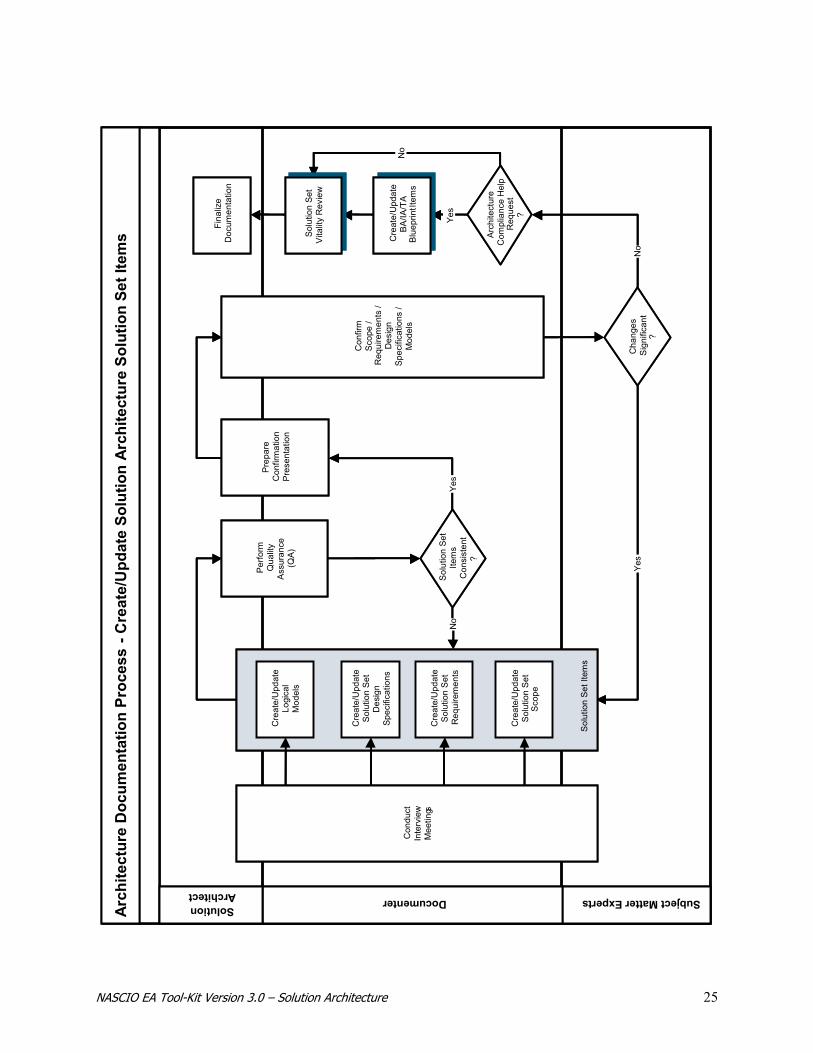
Create/Update Solution Set Items
The Solution Set items consist of the definition of solution scope, the solution requirements, design specifications, impacts, and logical models. These items, collectively known as a Solution Set, describe the overall design architecture for a specific solution effort or project.
PROCESS OVERVIEW
NASCIO EA Tool-Kit Version 3.0 – Solution Architecture 24
Solution Set specifics are identified during the Solution Architecture interview process and documented within each of the Solution Set views as appropriate. The Solution Architecture team, and Subject Matter Experts determine the information to be documented and which Solution Architecture views are necessary to complete the solution design specifications. For example, if the solution set type is an Application System, the views that would be documented might include: business, security, application, usability, and integration. The process would ensure that the Solution Architecture team collects the appropriate requirements, documents the matching design specifications, considers organizational and technical impacts, and lastly, builds the logical model for the solution. This process, which results in defining/updating the Solution Set items, collects, organizes and documents the data that pertains to the specific solution. The detail is collected via interviews with a mix of Subject Matter Experts, from executives through line managers. Getting good results from interviews of key staff requires a team composed of individuals who are experienced and have both knowledge of their area and a commitment to the enterprise architecture process.
NASCIO EA Tool-Kit Version 3.0 – Solution Architecture 25
Arch
itect
ure
Doc
umen
tatio
n Pr
oces
s-C
reat
e/U
pdat
e So
lutio
n Ar
chite
ctur
e So
lutio
n Se
t Ite
ms
Subject Matter ExpertsDocumenterSolutionArchitect
Yes
No
Yes
Yes
No
No
Fina
lize
Doc
umen
tatio
n
Cre
ate/
Upd
ate
BA/IA
/TA
Blu
eprin
t Item
s
Sol
utio
n S
et It
ems
Con
duct
Inte
rvie
wM
eetin
gs
Pre
pare
Con
firm
atio
nP
rese
ntat
ion
Cre
ate/
Upd
ate
Sol
utio
n S
etR
equi
rem
ents
Con
firm
Sco
pe /
Req
uire
men
ts /
Des
ign
Spec
ifica
tions
/M
odel
s
Solu
tion
Set
Vita
lity
Rev
iew
Sol
utio
n S
etIte
ms
Con
sist
ent
?
Per
form
Qua
lity
Ass
uran
ce(Q
A)
Cre
ate/
Upd
ate
Sol
utio
n S
etD
esig
nSp
ecifi
catio
ns
Cre
ate/
Upd
ate
Sol
utio
n S
etS
cope
Arch
itect
ure
Com
plia
nce
Hel
pR
eque
st?
Cre
ate/
Upd
ate
Logi
cal
Mod
els
Cha
nges
Sig
nific
ant
?
Arch
itect
ure
Doc
umen
tatio
n Pr
oces
s-C
reat
e/U
pdat
e So
lutio
n Ar
chite
ctur
e So
lutio
n Se
t Ite
ms
Subject Matter ExpertsDocumenterSolutionArchitect
Yes
No
Yes
Yes
No
No
Fina
lize
Doc
umen
tatio
n
Cre
ate/
Upd
ate
BA/IA
/TA
Blu
eprin
t Item
s
Sol
utio
n S
et It
ems
Con
duct
Inte
rvie
wM
eetin
gs
Pre
pare
Con
firm
atio
nP
rese
ntat
ion
Cre
ate/
Upd
ate
Sol
utio
n S
etR
equi
rem
ents
Con
firm
Sco
pe /
Req
uire
men
ts /
Des
ign
Spec
ifica
tions
/M
odel
s
Solu
tion
Set
Vita
lity
Rev
iew
Sol
utio
n S
etIte
ms
Con
sist
ent
?
Per
form
Qua
lity
Ass
uran
ce(Q
A)
Cre
ate/
Upd
ate
Sol
utio
n S
etD
esig
nSp
ecifi
catio
ns
Cre
ate/
Upd
ate
Sol
utio
n S
etS
cope
Arch
itect
ure
Com
plia
nce
Hel
pR
eque
st?
Cre
ate/
Upd
ate
Logi
cal
Mod
els
Cha
nges
Sig
nific
ant
?

NASCIO EA Tool-Kit Version 3.0 – Solution Architecture 26
Conduct Interview Meetings – When the subject matter experts have been identified and the interview strategy has been determined, the interview meetings can be scheduled. When obtaining and documenting the Solution Set requirements, allow at least two hours per session. More sessions may need to be conducted depending upon the complexity of the Solution Set and the various Solution Set views that need to be documented. It is also quite possible that several sessions will need to be conducted to document the Solution Set Design Specification and solution impacts. These sessions should allow enough time for the experts to identify all the design criteria. Items that will contribute to successful interviews include:
• Plan the Meeting Topics – Meetings are typically organized around a specific view within the Solution Set. The views should have been determined during an interview strategy session, which is typically one of the first work sessions scheduled. Often, new requirements and views will surface during the interviews. If this occurs, these should be documented and the original strategy modified to assure that all views of the Solution Set area addressed in the interviews. It is best to assign each interviewer a specific Solution Set view for which they are responsible. Though everyone will be involved in the interviews from a general view, it helps to give each interviewer an area of focus based on the view to be covered for the proposed Solution Set. Before the interviews, each interviewer should plan questions based on their assigned view. This will help to ensure the coverage of all aspects. It is also helpful to have an individual assigned as a scribe. This allows the interviewers to focus their attention primarily on the interviewing process and less on taking notes.
• Produce Meeting Notes – Knowing who participated in providing the subject matter is very useful. During the interview sessions, Subject Matter Experts or various architecture participants may be asked to follow up with action items or to share documentation and research on specific items. For this reason, meeting notes should be taken, reproduced and distributed as they are done for any other formal meeting. Parking lot issues or unresolved items often result during interview meetings. These items need to be compiled, returned to the person interviewed for feedback, and documented in the interview strategies or the summary documentation.
• Conduct Follow-up – Following interview meetings with subject matter experts, some items may require resolution or additional action. These activities may include, but are not limited to, the following: − Changes to Interview Strategy: Based on interview feedback, the style and/or strategy of subject
matter expert interviews may be changed − Resolution of Items: Dissention or ambiguity may necessitate resolution and/or direction from
Architecture Subject Matter Experts, Executives, Managers or Reviewers − Clarification: The Documenters may need additional information on a topic − Parking Lot Items: Items that are currently out of the defined scope, but have been identified as
potentially requiring future action Create/Update Solution Set Scope – The Solution Architect and Documenters, with input from the appropriate Subject Matter Experts will define the scope of the Solution Set. This will also include boundary statements and links to the reference material that will be needed when completing the rest of the solution set requirements and design specifications. The Solution Set Scope template is a form that can be used for documenting this detail. See Solution Set Scope Template.
PROCESS DETAIL
NASCIO EA Tool-Kit Version 3.0 – Solution Architecture 27
Create/Update Solution Set Requirements – The Documenters and Solution Architect capture detail about the Solution Set requirements, such as the specific views being addressed, the sub-category of the requirement, requirement statements, requirement owners, and the related EA components that identified the original business need. The Solution Set Requirements template is a form that can be used for documenting this detail. See Solution Set Requirements Template. Create/Update Solution Set Design Specifications – The Documenters and Solution Architect capture detail about the Solution Set design specifications such as the specific views being addressed, the sub-category of the design specification, design specification statements, and the related EA components that satisfy the design. The Solution Set Design template is a form that can be used for documenting this detail. See Solution Set Design Template. Create/Update Logical Models – Upon completion of documenting the Solution Set requirements, design specifications, organizational impacts, and technical impacts, the Solution Architect is ready to build the Solution Set Logical Model. The model is a graphical representation of the Solution Set and is typically inserted or referenced on the Solution Architecture Requirements Template. This template is a form that contains the design specifications and it can be used for referencing the logical model as well. See Solution Set Design Template. Perform Quality Assurance (QA) – The various Solution Set items and models require verification by the architecture team prior to confirmation with the Subject Matter Experts. This quality assurance step allows the team to verify that the various components are utilizing the same glossary of terms and that the team’s understanding of the various components of the Solution Set is the same. Prepare Confirmation Presentation – The Solution Architect and Documenters will compile the information from the meeting notes, the documented Solution Set and associations, and the quality assurance check. This information will be utilized to confirm the accuracy of the information captured. Confirm Scope/Requirements/Design Specifications/Models – Once the architecture team has verified consistency in how they are defining and representing the Solution Set, the team will confirm the requirements, design specifications and logical models with Business and Technology Subject Matter Experts. This should be an interactive session where modifications and enhancements are noted. Some changes can occur during the session, while others will take more time and will be conducted in “pick-ups” after the session. If the changes to the requirements/design specifications/models take place outside the session, an electronic copy of the changes should be sent out for approval. If the changes were significant, the potential exists to call another meeting to confirm those changes. Create/Update BA/IA/TA Blueprint Items – If components are identified during the Solution Set documentation process that are needed for the particular Solution Set but do not currently exist as part of the architecture, the appropriate Business, Information or Technology Architecture Blueprints should be updated. However, this should be initiated via an Architecture Help Request so the proposed blueprint changes are coordinated with the appropriate architecture and governance community.
• For updates to the Business Architecture Components see Business Architecture – Create/Update Business Architecture Blueprint Items
• For updates to the Process and/or Information Meta Components see Information Architecture – Create/Update Information Architecture Blueprint Items
• For updates to the Product and/or Compliance Components see Technology Architecture – Create/Update Technology Architecture Blueprint Items
Solution Set Vitality Review – The Solution Architect and Documenters will perform a vitality review of all items in the Solution Set ensuring that the proposed Solution Set is still valid and does not need to be
NASCIO EA Tool-Kit Version 3.0 – Solution Architecture 28
updated to reflect the results of the Architecture Compliance Help Request or additions or updates to Business Architecture, Information Architecture, or Technology Architecture blueprints. If changes are necessary, then the team must initiate the Solution Set Vitality Review process. Finalize Documentation – When the Solution Set detail has been confirmed, an update of the status and audit trail detail will occur. The final action is to submit all Solution Set details for inclusion in the Solution Architecture documentation.
Solution Set Scope Template
The Solution Set Scope template provides an instrument for documenting the scope of the solution in an electronic format. The visual representation of the Solution Set Scope template is followed by a detailed description of the contents to be captured. When populated, this template provides the necessary background information for the effort. It contains a link to the proposed solution’s conceptual model contained in the Implementation Plan as well as links to all the reference material that will be needed when completing the rest of the solution set requirements and design specifications. Important items to keep in mind when completing the Solution Set Scope template are:
• The Solution Set Scope template reuses critical information previously identified in the allied architecture processes.
• The information referenced on the Solution Set Scope template is used to ensure that the Solution Architect has a complete view of all the known information about the effort being undertaken. Various pieces of information, such as high-level requirements and dependencies, are contained in the associated gap and migration strategies. Other information, such as the proposed future state, is identified on the original Business Architecture, Information Architecture, or Technology Architecture blueprints. Project specific information, such as project dependencies, risk analysis, cost/benefit analysis, and the conceptual model designed for the solution are contained within the specific Implementation Planning item. The Solution Set Scope template brings all this information together.
• The Solution Set may address multiple solution types. It may be possible for a Solution Set to have a combination of a business solution and an application solution that need to be designed. If this is the case, a Solution Set Scope template and Solution Set Requirements templates should be completed for these Solution Set types.
• The conceptual model for the solution set is created as a part of Implementation Planning.
The conceptual model, which will be used during the Solution Architecture process, is created during the Implementation Planning effort. The conceptual model and the high-level requirements that are documented during the Implementation Planning process are used to frame or scope the Solution Set effort.
TEMPLATE OVERVIEW
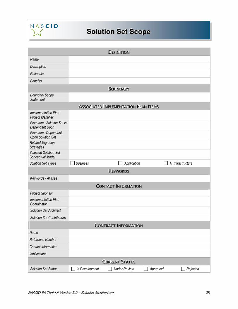
NASCIO EA Tool-Kit Version 3.0 – Solution Architecture 29
SSSooollluuutttiiiooonnn SSSeeettt SSScccooopppeee
DDDEEEFFFIIINNNIIITTTIIIOOONNN Name
Description
Rationale
Benefits
BBBOOOUUUNNNDDDAAARRRYYY Boundary Scope Statement
AAASSSSSSOOOCCCIIIAAATTTEEEDDD IIIMMMPPPLLLEEEMMMEEENNNTTTAAATTTIIIOOONNN PPPLLLAAANNN IIITTTEEEMMMSSS Implementation Plan Project Identifier
Plan Items Solution Set is Dependant Upon
Plan Items Dependant Upon Solution Set
Related Migration Strategies
Selected Solution Set Conceptual Model
Solution Set Types Business Application IT Infrastructure
KKKEEEYYYWWWOOORRRDDDSSS Keywords / Aliases
CCCOOONNNTTTAAACCCTTT IIINNNFFFOOORRRMMMAAATTTIIIOOONNN Project Sponsor Implementation Plan Coordinator
Solution Set Architect
Solution Set Contributors
CCCOOONNNTTTRRRAAACCCTTT IIINNNFFFOOORRRMMMAAATTTIIIOOONNN Name
Reference Number
Contact Information
Implications
CCCUUURRRRRREEENNNTTT SSSTTTAAATTTUUUSSS Solution Set Status In Development Under Review Approved Rejected

NASCIO EA Tool-Kit Version 3.0 – Solution Architecture 30
AAAUUUDDDIIITTT TTTRRRAAAIIILLL Creation Date Date Accepted / Rejected
Created By
Reason for Rejection
Last Date Reviewed Last Date Updated
Updated By
Reason for Update
NASCIO EA Tool-Kit Version 3.0 – Solution Architecture 31
DEFINITION Name – The Solution Architect will determine the name for the solution set based on the associated Implementation Plan item. It should be followed by the type of template (e.g., Solution Set Scope, Requirements, or Design) because the name will be used again as the Plan name. Example: Department of Human Resources Portal – Solution Set Scope. Description – An appropriate description of the solution being undertaken in a paragraph or two that provides sufficient clarity to the reader about the effort. It should clearly identify the specific migration strategy that is being undertaken and how this migration strategy impacts any other associated migration strategies (if necessary). Rationale – An explanation of the reason(s) for this solution being designed and implemented. This could include linkages to strategic and/or operational plans or other business drivers Benefits – A paragraph or bulleted statements that provide the benefits associated with the solution. BOUNDARY Boundary Scope Statement – The boundary scope statement provides parameters for identifying the boundaries for the solution. This section includes statements about what is included, as well as items that are related to, but excluded from, the solution. If this is an incremental solution it is important to denote that this is a portion of the overall solution. ASSOCIATED IMPLEMENTATION PLAN ITEMS Implementation Plan Project Identifier - Identify the associated Implementation Plan item that this Solution Set is addressing and follow it by the actual name of the Implementation Plan item name. Plan Items Solution Set is Dependent Upon – List any other Implementation Plan items that are dependent upon this solution’s implementation. This is important because if this solution is not completed the other plan items will also not be able to be completed. The list should contain the plan item number followed by the name of the plan item. Plan Items Dependent Upon Solution Set – List any other Implementation Plan items that are dependent upon this solution’s implementation. This is important because if this solution is not completed the other plan items will not be able to be completed either. The list should contain the plan item number followed by the name of the plan item. Related Migration Strategies – Document the related Migration Strategy for the Solution. The Migration Strategy is part of the Implementation Plan. Selected Solution Set Conceptual Model – Document the link to the associated Conceptual Model that was used to establish the high-level view of the solution set. This Conceptual Model is a part of the associated Plan Item number. Solution Set Types – List the type of solution that will be designed for this Solution Set effort. The solution may consist of one or more solution types. This may include the following:
• Business Solution – The solution will implement a business process improvement, organizational change, or other type of business solution.
TEMPLATE DETAIL

NASCIO EA Tool-Kit Version 3.0 – Solution Architecture 32
• Application Solution – The solution will involve the purchase and/or development of an application system.
• IT Infrastructure Solution – The solution will involve the purchase and/or design of IT infrastructure components
KEYWORDS Keywords / Aliases - List any keywords that can be used to assist in searching the repository for information about the solution being designed and implemented. This information will be helpful for anyone looking for information regarding similar elements. CONTACT INFORMATION Project Sponsor - Identify the ultimate decision maker for the Solution Set. This may be the Project Sponsor, the Project Champion, or the Project Owner. This individual is typically responsible for (1) funding the solution, (2) ensuring that it remains a priority on the Implementation Plan, (3) providing the solution requirements, and (4) Approving/Accepting the Implemented Solution. Implementation Plan Coordinator – Provide the name and contact information of the individual responsible for maintaining the detailed information on the Implementation Plan. This individual will be responsible for communication and coordinating external solution set requirements with the respective areas as well as with linked plan items. Solution Set Architect – Identify the name of the primary architect who will be designing the solution. This will also be the individual who will work with the project team to obtain architectural review and approval of the design. Solution Set Contributors - List the names and contact information of the individuals who will work with the Solution Architect to establish the requirements and design specifications for this solution set. One of the contacts should be identified as the solution set owner or business project manager. The designated persons should have sufficient knowledge of the solution set to be able to provide additional information or points of contact as needed. Other individuals listed should include Subject Matter Experts who will contribute to the various requirements (e.g. Security, Information). CONTRACT INFORMATION If this solution set is impacted by or is impacting an existing contract this relationship and an impact statement need to be documented. Contracts may impact specific Solution Set designs in terms of licensing requirements, simulations usage, authorizations, and so forth. The Solution Architect should also consider potential contract impacts to existing organizational contracts, contracts leveraged but owned by other government agencies, and contracts with customers or suppliers. This section should be repeated for each contract that will be impacted by, or will impact, the specific Solution Set. Name – List the specific contract name. Reference Number – List the specific contract reference number that identifies the contract. Contact Information – List the agency, vendor, or unit that provides ownership and review of the contract. In addition, list the address and telephone number of the contact point.

NASCIO EA Tool-Kit Version 3.0 – Solution Architecture 33
Implications – Document the specific contract implications that will occur if the Solution Set is approved and implemented. If the contract has impacted the Solution Set design, list what was impacted and how this impact is going to be resolved. CURRENT STATUS Solution Set Status – Document the status of the Solution Set, indicating whether the component is in development, under review, accepted, or rejected.
• In Development – The architecture team is currently crafting and/or reviewing the Solution Set detail.
• Under Review – The architecture team has completed the Solution Set documentation and it has been submitted for review. Possible reviewers may include members of the project team, the technical community, and the business community.
• Accepted – The Solution Set has been approved for submission to the appropriate build team. • Rejected – The Solution Set has been rejected for reasons documented below in the Audit Trail
section. AUDIT TRAIL Creation Date – Provide the date the Solution Set was created. Created By – List the names and titles of the individuals who contributed to the creation of the Solution Set. Date Accepted/Rejected – Provide the date the Solution Set was accepted or rejected. Reason for Rejection – If the Solution Set was rejected, document the reason for the rejection. A Solution Set may be rejected for many reasons including, but not limited to, the following:
• Priority, resource, or timing issues rendered the Solution Set not viable at this time. Although the Solution Set is considered rejected for implementation, the original Implementation Planning items remain in effect should the project be re-initiated.
• The Solution Set represented one of several options for delivering the required functionality to the organization and another option was chosen. If this happens, the original Implementation Plan item should also be rejected and removed from the Implementation Plan.
• Predecessor projects were determined to have been necessary, so the Solution Set was put on hold until successful completion of the identified projects. Although the Solution Set is considered rejected for implementation, the original Implementation Planning items remain in effect should the project be re-initiated.
• Necessary architecture components were identified as missing from the existing Enterprise Architecture blueprint. In this event, the Solution Set project must wait until the architecture gaps are filled. Although the Solution Set is considered rejected for implementation, the original Implementation Planning items remain in effect should the project be re-initiated.
Last Date Reviewed – Document the most recent date the Solution Set was taken through the Solution Set Vitality Process. This will occur if the Solution Set has been changed after the solution design has previously been approved but not executed. Last Date Updated – Document the most recent date that any item in the Solution Set documentation was changed.
NASCIO EA Tool-Kit Version 3.0 – Solution Architecture 34
Updated By – List the names and titles of the individuals who updated this Solution Set. Reason for Update – Document the reason for the update to the Solution Set.
Solution Set Requirements Template
The Solution Set Requirements template provides a tool for documenting the Solution Set requirements in an electronic format. To aid the Solution Set Architect and Documenters, requirements are categorized into types, thereby enabling the team to identify the Subject Matter Experts with whom coordination is necessary during the development of the Solution Set. Some typical solution types may include:
• Business Solution – The solution will implement a business process improvement, organizational change, or other type of business solution.
• Application Solution – The solution will involve the purchase and/or development/modification of an application system.
• IT Infrastructure Solution – The solution will involve the purchase and/or design of IT infrastructure components.
When completely populated, this template provides the detailed requirements necessary to create the solution design. REQUIREMENT VIEWS The Solution Set Requirements template is designed to be generic in nature because each “view” requires documentation that is structurally similar. The template sections can be repeated as necessary to accommodate any combination of solution types and views. This keeps the template simple, while allowing for the documentation of specific requirements based upon the needs of the solution set. The Solution Set Requirements template is organized by “views” and “categories”. The various views and categories, defined below, help to further identify Subject Matter Experts and ensure that the necessary Solution Set requirements are identified. These views are also used when identifying the associated design specifications and the logical design models after data collection and analysis. The list of potential views for the Solution Set Requirements template is described below. Business View
The Business View provides a tool for documenting business requirements that will be addressed in the solution. These requirements relate to anything causing changes or updates to the following:
• Financial – Monetary or accounting systems that systematically record, present, and interpret financial accounts.
• Strategy and planning – The processes that select, design and support decision making for the direction of the enterprise, including business drivers.
• Policy – The governing principle, plans or rules which guide organizational behavior.
TEMPLATE OVERVIEW

NASCIO EA Tool-Kit Version 3.0 – Solution Architecture 35
• Organizational – The arrangement or organization structure of the enterprise and the related human resources systems,
• Procedure – The established sequence of steps in a process or activity. • Business Cycle – The regular alternation of periods of business activity. • Logistical – Procuring, maintaining, and transporting materials, personnel and facilities.
Most organizations have standard development methods that may include questionnaires to be used during interviews to populate the business requirements portions of the templates. The Software Engineering Institute2 is a good source for questionnaire information. Information View
The Information view examines and documents the data element and data element concepts needed for the solution. The categories associated with Information are in the form of Process Components and Meta Data Components. For a detailed explanation of these categories, please reference the Information Architecture section of the Tool-kit. Security View
The Security View provides a tool for documenting how security requirements will be addressed in the solution. In addition, it also specifies the security processes, controls, and/or technologies that will be used to implement the solution depicted in the Solution Set logical models. Most organizations have a standard development methodology that may include questionnaires to gather detail to populate the security portions of the templates. The National Institute of Standards and Technology3 is a good source for questionnaire information and for detailed definitions of the categories used within the Security View area of the template. Security Requirements can be expressed in many ways; however, one that is standard in the industry is “controls4”. These features, often expressed as Managerial, Operational, and Technical Requirements, are gathered and used to identify the security specifications completed during the Solution Set Design. The types of Security Controls are: Managerial Controls – Address security topics that can be characterized as managerial. These controls are techniques and concerns that are normally addressed by management in the organization's computer security program. In general, these controls focus on the management of the computer security program and the management of risk within the organization. Topics generally covered in Management Controls include:
• Security Policy • Security Program Management • Security Risk Management • Security & Planning in the SDLC • Assurance
2 http://wwwsei.cmu.edu/ 3 http://www.nist.gov/ 4 Special Pub 800-12 -- An Introduction to Computer Security: The NIST Handbook

NASCIO EA Tool-Kit Version 3.0 – Solution Architecture 36
Operational Controls – Address security controls that focus on controls that are implemented and executed by people (as opposed to systems). These controls are put in place to improve the security of a particular environment, system, or group of systems. These often require technical or specialized expertise and often rely upon management activities as well as technical controls. Topics generally covered in Operational Controls include:
• Personnel/User Issues • Contingencies & Disaster Planning • Security Incident Handling • Awareness, Training, & Education • Security Considerations in Support & Operations • Physical & Environment Security
Technical Controls - Focus on security controls that the computer system executes. These controls are dependent upon the proper functioning of the system for their effectiveness. The implementation of technical controls, however, always requires significant operational considerations and should be consistent with the management of security within the organization. Topics generally covered in Operational Controls include:
• Identification & Authentication • Logical Access Control • Audit Trails • Cryptography
Application View
There are several categories of requirements that must be addressed when designing an application system. These categories include end-user services, application infrastructure, and application structure and usability. Wherever possible, application detail is leveraged from pre-existing documentation. Be careful not to baseline existing systems that exhibit significant deficiencies or do not satisfy a high percent of future requirements. The Application View applies to various forms of Application development efforts including:
• New Development - A totally new system development implies that there is no existing system. You have a blank sheet of paper and total latitude in defining its requirements and design. In reality this is a rather rare occurrence.
• Rewrites of an Existing System – In a rewrite there is an existing system; however, the system may be limited in its ability to absorb major modifications (e.g., such as integrating with a new portal) while minimizing the impact to the rest of the system. Maintainability may have become an issue, vendors may have provided all or the bulk of the support, underlying platforms may have changed, and so forth. When this situation occurs, it is usually desirable to maintain the core functionality of the business system. As a result, the original system is re-written to accommodate the new environment (e.g., replacing a batch system with an online system, moving it from a centralized system to a distributed system), but the system performs the same function (e.g., payroll processing, license renewals).
• Maintenance – Incremental improvements to an existing system, regardless of the size of the changes.

NASCIO EA Tool-Kit Version 3.0 – Solution Architecture 37
• Package Selection - Package selection involves evaluating, acquiring, tailoring and installing third party software.
• System Conversion - A system conversion involves translating a system into a new environment. This includes conversions to a different programming language, operating system, computer, disk drives, Data Base Management System, etc. In the translation, the system is not redesigned. It is ported to the target environment, to the extent possible, on a line-for-line basis.
A sample list of the Application View categories, which are related to the characteristics of the application itself, include:
• Functionality – The specific functions that the application performs. This category covers the actual application capabilities itself such as reading, writing, calculating and displaying data, extracting, comparing, and loading data from other files and so forth.
• Performance - Performance requirements describe how fast the system must complete transformations, how many must be completed, and any limitations on the amount of utilization of the agents used to support the transformation (e.g., amount of machine time, amount of disk space).
• Reliability - Reliability defines the degree of accuracy required in the transforms. In billing this would be 100%. In weather forecasting it could be plus or minus 5% for a short term forecast.
• Availability - Availability defines the amount of time the system is available during the time periods when it is supposed to be available. This is usually defined as a percentage, qualified with standard deviations. Mean time to failure, by type of failure, further defines system availability.
• Serviceability - Serviceability addresses how quickly the system can be corrected when it is discovered to be unreliable or unavailable. This might be expressed as the mean time to fix. Mean time to fix is usually qualified by the type and severity of the failures. Serviceability can also be affected by the capability of remote system access and/or local service staff.
• Localization - Localization describes the ability to adapt the application to different languages, character sets, and cultures to support international users. This also relates to the capability of the system to match the business processes of the organization as well as changes to the look and feel, and navigational aspects of the GUI.
• Portability - Portability describes the need to be able to quickly adapt the application to run on different technology.
• Maintainability - Maintainability describes the need for people to be able to quickly and reliably identify where changes must be made to the system.
• Testability - Testability describes what is being tested, when testing must occur, the steps in testing, the properties to being tested, and the definition of the overall testing effort.
• Extendibility - Extendibility describes the system's ability to absorb major modifications to changes in any of the above requirements, while minimizing the impact to the rest of the system. This is usually described in terms of change scenarios accompanied with the probability that the change will be needed and the probable time frame in which it will occur. Extendibility also relates to the capability of the technology to expand without major additions to infrastructure. In the integration space this would mean an architecture would be initially capable of supporting several agencies and business process exchanges and without major changes be capable of adding many agencies and exchanges.
• Retainability - Retainability describes how the system manages the retention of various data items based on formal retention policies.
NASCIO EA Tool-Kit Version 3.0 – Solution Architecture 38
Usability View
Usability requirements describe the ergonomics of the system (e.g., ease of correctly interpreting the information on a screen). The categories defined within the Usability view may include:
• GUI – Graphic User Interface requires (GUI) a description of the user interface screens showing the graphics required and the graphic structure for the screen interface. This would include screen layouts and navigation between windows or screens.
• Reports – Reports outline the requirements for the presentation of information gathered from a database via pre-determined parameters that may or may not be run at scheduled intervals. This information can be used visually from displayed output data sets or output within hard copy.
• Forms – This is similar to the GUI because this is a representation of the expected detail that would be collected via a screen form. . It can also relate to the output generated from the on-line data entry.
• Accessibility – This lists the requirements to comply with accessibility needs of the application, such as those required by Section 508 of the Rehabilitation Act: Accessibility for People with Disabilities in the Information Age. Detailed information on Section 508 can be found at: http://www.usdoj.gov/crt/508/report2/standards.htm.
• Queries – This contains the detail necessary to build queries from the desktop. • Other – Any other detail deemed necessary to meet the Usability Requirements
Infrastructure View
The Infrastructure View is intended to guide the Solution Architect in capturing all the requirements and design considerations involving the usage of IT infrastructure components or services. The Infrastructure View identifies the technical components in the architecture that are being introduced or changed, as well as any impacts on other technology components required for functionality. It also addresses the impact on roles, policies, and standards required within the infrastructure to support the solution. Some examples of the various types of infrastructure can be seen in the list that follows. It is important to understand however, that this list is only representative of the typical EA categories used to classify IT Infrastructure and may not match those developed within your organization. Examples of categories within an Infrastructure View include:
• Voice & Video (e.g., CTI, Telephones, IP Telephony, PBX, Video Conferencing, IVR) • Network – Software (e.g., Protocols, Access Methods, DHCP, WINS, DNS) • Network – Hardware (e.g., Switches, Routers, Hubs, Bridges, Content Services, RAS, Modems,
Sniffers, LAN/WAN/MAN) • Security Systems (e.g., Firewall, Intrusion Detection System, Access Control Servers) • Storage Devices (e.g., SANs, RAID, Tape Drives/Libraries, Disk, Optical CDs, Removable Media) • Platform – Hardware (e.g., Desktops, Laptops, Workstations, Servers) • Platform – Software (e.g., Operation Systems for Mainframe, Mid-Range, Server) • Systems Management (e.g., Change Control, Problem Resolution, Asset Management) • Productivity Tools (e.g., Office XP, MS VISIO, MS Project, Word Perfect, Lotus) • Databases (e.g., Relational, Hierarchical) • External Service Providers (e.g., ISP, VPN, Voice Mail, Satellite, Paging, Cellular)

NASCIO EA Tool-Kit Version 3.0 – Solution Architecture 39
• I/O Devices (e.g., Printers, Monitors, Scanners, Copiers, Wireless Storage, Digital Camera, Facsimiles)
• Utilities (e.g., Performance Monitors, ISPF, JES2, Disc Defrag, Installation Utilities, TSO/E, CICS)
The Infrastructure View often leverages pre-existing infrastructure patterns where possible, thus enabling rapid development of the design and the solution set. These infrastructure patterns represent the bundling of various components of the Technology Architecture. These patterns help to jump-start the design process by identifying all the necessary infrastructure components required to deliver or develop the solution. Some examples of infrastructure patterns that organizations often find useful pertain to the bundling of components that deliver application capabilities:
• Transact – Applications that store business data for long periods of time, such as online customer order and other transactions, usually working with only one record or possibly a few records at a time
• Publish – Applications with read-only data, such as state highway transportation project information published in Web pages and made viewable to the public
• Collaborate – Applications that allow users to share information contained in files and documents, such as a word processing documents shared by a development team or an e-mail driver customer support system
Publish patterns, for example, can be further defined as Client/Server Publish, Web Publish, and Stream Publish. Each pattern would contain all the necessary information for the client or front-end component (e.g., PC, kiosk), the server types needed (e.g., web server, database server, application server) and the technologies utilized to build the application (e.g., XML, XQL, HTML/HTTP). This information is useful to the Solution Architect because it lays out the various architectural components that are needed to design the solution. In many organizations, the Solution Architect is initially aligned with a particular business unit. This enables the Solution Architect to focus on the specific needs of the business unit’s application portfolio. However, this may also cause the Solution Architect to inadvertently build silo solution sets. From an enterprise perspective, it may be more advantageous to align the Solution Architect by skill set as opposed to business unit, as it ensures reuse and application of various architecture components. For example, if the organization has built patterns, the Solution Architect can be aligned by skill set (e.g., Web Publishing) thus ensuring the systematic re-use of the components in the architecture pattern. The knowledge of the specific business unit should have been captured within the Business Architecture. That data, along with the input from the various line of business subject matter experts, should ensure that the Solution Architect has the appropriate business-specific knowledge to develop the pattern-based design. For more information about these types of infrastructure patterns and a discussion on the understanding, development and usage of infrastructure patterns in general, please refer to the book Enriching the Value Chain: Infrastructure Strategies Beyond the Enterprise5. This book, produced by META Group, provides an excellent dialog on patterns and other key infrastructure services. 5 Bruce Robertson and Valentin Sribar. Enriching the Value Chain: Infrastructure Strategies Beyond the Enterprise. Intel Corporation and META Group. 2002.

NASCIO EA Tool-Kit Version 3.0 – Solution Architecture 40
Integration View
The Integration View examines how the solution will integrate with the existing environment. Integration can occur at several touch or exchange points in order to incorporate processes, application, infrastructure, and those elements external to the organization. To further assist the Solution Architect in determining the possible integration requirements, the Integration View includes the usage of categories also. These categories, labeled Managerial, Operational, and Technical, encompass the following: Managerial - Includes human resources, skills, and training. Some examples of Managerial integration are:
• Skills • Training • Staffing Levels • Vendor Qualification
Operational – Includes those mechanisms implemented and executed by people. Integration of operational aspects must be evaluated for every part of the solution, for example:
• Hardware and System Support − Data Management Services − Security − Platform/Configuration − Network Services − Operations
• Operator Activities Associated with Servers and Print Queues • DASD Backup and Restore • Software Distribution to Servers and PCs • Asset Management and Inventory • Disaster Recovery and Planning
• Application Services • End User Services • Services Desk • Measurement/Reporting/Service Levels • Service Continuity and Consistency • Backup and Recovery • Documentation • Locations • Process

NASCIO EA Tool-Kit Version 3.0 – Solution Architecture 41
Technical – Includes the physical IT application, system, and equipment integration requirements including:
• Performance − Response Time − Availability − Transaction Throughput
• User Numbers Supported • Output • Accuracy • Timeliness • Capacity • Availability • Performance • Continuity • Scalability/Adaptability
The views and categories listed here are examples of items that are commonly addressed during solution design. The Solution Set templates provide a means for capturing requirements for any combination of views and categories. Organizations may wish to customize templates to include the views and categories that are most commonly addressed during solution design within their environment. The state of North Carolina has created a “System Design Template” that contains a detailed series of questions to ensure critical elements are addressed for each design. A copy of North Carolina’s “System Design Template” is available by accessing SMART at NASCIO’s website at www.nascio.org. The visual representation of the Solution Set Requirements Template, provided on the following page, is followed by the detailed description of its contents.

NASCIO EA Tool-Kit Version 3.0 – Solution Architecture 42
SSSooollluuutttiiiooonnn SSSeeettt RRReeeqqquuuiiirrreeemmmeeennntttsss
DDDEEEFFFIIINNNIIITTTIIIOOONNN Name
KKKEEEYYYWWWOOORRRDDDSSS Keywords / Aliases
SSSOOOLLLUUUTTTIIIOOONNN SSSEEETTT TTTYYYPPPEEE Type of Solution Business Application IT Infrastructure
RRREEEQQQUUUIIIRRREEEMMMEEENNNTTTSSS VVVIIIEEEWWW Requirements View Name
Category Name
Requirement Statement Requirement Owner Related EA Component
Category Name
Requirement Statement Requirement Owner Related EA Component
RRREEEQQQUUUIIIRRREEEMMMEEENNNTTTSSS VVVIIIEEEWWW Requirements View Name
Category Name
Requirement Statement Requirement Owner Related EA Component
CCCUUURRRRRREEENNNTTT SSSTTTAAATTTUUUSSS Solution Set Requirement Status In Development Under Review Approved Rejected
AAAUUUDDDIIITTT TTTRRRAAAIIILLL Creation Date Date Accepted / Rejected
Created By
Reason for Rejection
Last Date Reviewed Last Date Updated
Updated By
Reason for Update

NASCIO EA Tool-Kit Version 3.0 – Solution Architecture 43
The methods utilized for capturing requirements vary by organization. As a result, this template is designed to expand the solution set types, views, and categories, as needed, to accommodate the specifics of the solution set and the uniqueness of the organization. DEFINITION Name – The name of the solution set followed by the words “Solution Set Requirements”. The name of the Solution Set is obtained from the Solution Set Scope Template. For example: Customer Service Center –Solution Set Requirements KEYWORDS Keywords / Aliases – List any keywords that can be used in searching the repository for information about the solution being designed and implemented. This information will be helpful for anyone looking for information regarding similar elements. SOLUTION SET TYPE The solution set type is used to document the requirements specific to the type of solution being designed (e.g. business solution, application solution, IT infrastructure solution). This template area can be broken down into the various solution types and views so the Solution Architect can focus on the specific needs of a particular view independently. This is necessary because the resources required to gather specific requirements will typically be from different organizations. Type of Solution – Check the box that represents the type of Solution Set being documented in this section of the template. The Solution Set Type, along with the Requirements View sections, should be repeated for each solution type addressed by the Solution Set. REQUIREMENTS VIEW Within the Requirements View section, list each of the requirements within a specific solution set type. The most common views that may be documented for a solution set type include:
• Business View – Pertains to how business requirements will be addressed in the solution. This includes such requirements as financial, strategic planning, business cycles, organizational, business drivers, logistical, policy, and procedures. This view typically aligns with the information contained within the Business Architecture blueprints.
• Security View – Pertains to how security requirements will be addressed in the solution. These requirements may be in terms of physical security, human resource security, information security, and IT security. They are grouped into security categories known as management, operational and technical security controls.
• Information View - Pertains to how information requirements will be addressed in the solution. This typically includes such requirements as process flows, information ownership, metadata, spatial data, data architecture, data standards, document management, knowledge management, and content management.
• Application View – Pertains to how application system requirements and design considerations will be addressed in the solution. This typically includes such categories as application functionality, application structure, performance, reliability, availability, and maintainability.
TEMPLATE DETAIL
NASCIO EA Tool-Kit Version 3.0 – Solution Architecture 44
• Usability View - Pertains to how application system usability requirements and design considerations will be addressed in the solution. This typically includes the graphical user interface (GUI), any dialogs and queries that need to be performed by the application, any forms to be developed, any user reports that the system needs to produce, and accessibility needs.
• Infrastructure View - Pertains to how IT infrastructure requirements and design considerations will be addressed in the solution and typically includes such categories as hardware, software, voice, middleware, and databases.
• Integration View - Pertains to how the results of the Solution Set will integrate with components of the existing environment. This includes such integration requirements as process, application, infrastructure, and those external to the organization. It is also concerned with the impacts to the current environment involving training, resources, capacity, performance, and bandwidth. The integration requirements are addressed in the solution and are typically categorized as managerial, operational, or technical.
The Requirements View section should be repeated for each view that the Solution Set addresses. Requirements View Name – Provide the name of the view being completed for these requirements.
Category Name – The Requirement View Category allows for the division of Views into manageable subsets. Provide the name of the category that represents a logical subset of the Requirements View. For a list of potential categories for each of the Views, reference Solution Architecture – Framework. Example – Solution Set Type Name is Application, Requirements View Name is Usability, and the Requirements View Category is Accessibility.
The Category section should be repeated for each category within a view that the Solution Set addresses. For each requirement: Requirement Statement - List the requirements identified for this solution. These requirements should include sufficient detail to enable the completion of a resource assessment.
Requirement Owner - Document the name of the individual who will provide detail and ownership for the specified requirement. Also include contact information. If the specific requirement spans organizational functions, systems, locations, and providers, this may be more than one individual.
Related EA Component – List the related Business, Information, or Technology Architecture Component, associated Gap Component, and/or associated Migration Strategy component name that contained the original requirement for the Solution Set. This can be found as part of the documentation established during the development of the target architecture or during the Implementation Planning activities.
The Related EA Component represents the source of the requirement. It is possible, however, that the specific requirement was identified while creating the Solution Architecture Requirements and was not previously found in any of the existing EA component documentation. If this occurs, the Related EA Component field needs to identify this Solution Set Requirements Component as the source for the requirement.
The EA component type should be listed first and then be followed by the actual component name. Example: Process Component (Target) – New Employee Orientation. If it was identified during development of the template, the Related EA Component name may be Solution Set Requirements Component - Employee Background Security Checks.

NASCIO EA Tool-Kit Version 3.0 – Solution Architecture 45
CURRENT STATUS Solution Set Requirement Status – Document the status of the Solution Set, indicating whether the component is in development, under review, accepted, or rejected.
• In Development – The architecture team is currently crafting and/or reviewing the Solution Set detail.
• Under Review –The architecture team has completed the Solution Set documentation and it has been submitted for review. Possible reviewers may include members of the project team, the technical community, and the business community
• Accepted – The Solution Set has been approved for submission to the appropriate build team. • Rejected – The Solution Set has been rejected for reasons documented below in the Audit Trail
section. AUDIT TRAIL Creation Date – Provide the date the Solution Set was created.
Created By – List the names and titles of the individuals responsible for the creation of the Solution Set.
Date Accepted/Rejected – Provide the date the Solution Set was accepted or rejected.
Reason for Rejection – If the Solution Set was rejected, document the reason for the rejection. A Solution Set may be rejected for many reasons including, but not limited to, the following:
• Priority, resource, or timing issues rendered the Solution Set not viable at this time. Although the Solution Set is considered rejected for implementation, the original Implementation Planning items still remain in effect should the project be re-initiated within a limited period of time.
• The Solution Set represented one of several options for delivering the required functionality to the organization and another option was chosen. If this happens, the original Implementation Planning item should also be rejected and removed from the Implementation Plan.
• Predecessor projects were determined to have been necessary so the Solution Set was put on hold until successful completion of the identified projects. Although the Solution Set is considered rejected for implementation, the original Implementation Planning items still remain in effect should the project be re-initiated within a limited period of time.
• Necessary architecture components were identified as missing from the existing Enterprise Architecture blueprint. In this event, the Solution Set project must wait until the architecture gaps are filled. Although the Solution Set is considered rejected for implementation, the original Implementation Planning items still remain in effect should the project be re-initiated within a limited period of time.
Last Date Reviewed – Document the most recent date the Solution Set was taken through the Solution Set Vitality Process. This will occur if the Solution Set has been changed after the solution design had previously been approved but not executed.
Last Date Updated – Document the most recent date that any item in the Solution Set documentation was changed.
Updated By – List the names and titles of the individuals that updated this Solution Set.
Reason for Update – Document the reason for the update to the Solution Set.

NASCIO EA Tool-Kit Version 3.0 – Solution Architecture 46
Solution Set Design Template
The Solution Set Design template provides a tool to assist in documenting the design detail for the Solution Set. The Solution Set Design template is used to capture various design specifications, dependencies and other organizational and environmental impacts. It also provides links to existing enterprise architecture artifacts, models, and patterns. The design specifications documented in the Solution Set Design template address the specific requirements captured in the Solution Set Requirements. The design specifications, captured in narrative, will also be rendered on Logical Design Models, which provide a pictorial view of how the pieces work together to form the Solution Set. The detail from the Solution Set Design provides the basis for the physical design models, which is accomplished as part of the standard business process development or SDLC methodologies within the organization. Important items to keep in mind when documenting the Solution Set Design Specification are:
• The Solution Set Design template provides the structure to leverage component detail that already exists within the architecture
• One design specification may meet one or more requirements • Specifications should be in sufficient detail to enable the completion of a detailed design • Links to the requirements ensure the Solution Set Requirements have been addressed.
The visual representation of the Solution Set Design template, provided on the following pages, is followed by the detailed description of its contents. The development of the Solution Set Design is a process that will evolve and change as information is gathered and documented.
TEMPLATE OVERVIEW

NASCIO EA Tool-Kit Version 3.0 – Solution Architecture 47
SSSooollluuutttiiiooonnn SSSeeettt DDDeeesssiiigggnnn
DDDEEEFFFIIINNNIIITTTIIIOOONNN Name
KKKEEEYYYWWWOOORRRDDDSSS Keywords / Aliases
SSSOOOLLLUUUTTTIIIOOONNN SSSEEETTT TTTYYYPPPEEE Type Name
Design View Design View Name
Category Name
Design Specification Statements Related EA Component
Related Requirements Relationship
Category Name
Design Specification Statements Related EA Component
Related Requirements Relationship
Design View
Design View Name
Category Name
Design Specification Statement Related EA Component
Related Requirements Relationship

NASCIO EA Tool-Kit Version 3.0 – Solution Architecture 48
SSSOOOLLLUUUTTTIIIOOONNN SSSEEETTT LLLOOOGGGIIICCCAAALLL MMMOOODDDEEELLL Source Document
CCCUUURRRRRREEENNNTTT SSSTTTAAATTTUUUSSS Solution Set Design Status In Development Under Review Approved Rejected
AAAUUUDDDIIITTT TTTRRRAAAIIILLL Creation Date Date Accepted / Rejected
Created By
Reason for Rejection
Last Date Reviewed Last Date Updated
Updated by
Reason for Update

NASCIO EA Tool-Kit Version 3.0 – Solution Architecture 49
The Solution Set Design Template is utilized to document the design considerations after a logical model has been approved.
DEFINITION Name – The name of the Solution Set followed by the template name. The name of the Solution Set is obtained from the Solution Set Scope Template. For example: Customer Service Center – Solution Design. KEYWORDS Keywords/Aliases – List any keywords and/or aliases that can be used in searching the repository for information about the solution design. This information will be helpful for anyone looking for information regarding similar elements. SOLUTION SET TYPE Type Name - The name of the Solution Set followed by the solution type. For example: Customer Service Center – Business Solution. The Solution Set type names for Solution Design should match the solution set type names for the Solution Requirements. One or more solution set types can be documented by repeating the Solution Set Type section for each type. Design View
Design View Name – Provide the Design View Name. The Design Views within each Solution Set Type should also map to the Requirement Views covered by the Solution Set Requirements. Examples of Design Views include, but are not limited to:
• Business • Information • Application • Infrastructure • Security • Integration • Usability
Category Name – The category name allows for the division of Views into manageable subsets. The Categories documented for the Solution Set Design will match those used for Solution Set Requirements. The following information should be documented for each category. Design Specification Statements – List the design specifications identified for this design view. Specifications should be in sufficient detail to enable the completion of a detailed design.
• Security View - Specify the security classification for any associated data • Information View - The Logical and Physical target (future) view of the information is captured in
the Solution Architecture, however, because the level of detail for the Information View is similar
TEMPLATE DETAIL
NASCIO EA Tool-Kit Version 3.0 – Solution Architecture 50
in structure to the detail captured for the baseline documentation in Information Architecture, the logical detail will be captured utilizing the template provided in the Information Architecture Section of the Tool-Kit.
• Integration View - List the specific integration dependency or integration specification identified for this solution. These items should be in sufficient detail to articulate the need, identify how it will impact the environment, and identify who should resolve this impact.
Related EA Component – List the EA component that is related to each design specification. EA components can come from the Business, Information and/or Technology Architectures. If the organization uses patterns (commonly bundled EA Components), the pattern can also be listed here. If the design specification cannot be satisfied by any EA components identified to date, a gap should be identified so that steps can be taken to get the component documented within the architecture. This is accomplished by creating an EA Help Request. EA Help Requests are addressed as part of the EA Compliance Process (see Governance: EA Lifecycle Processes – Compliance Process). A standard phrase should be used to identify these gaps, such as “EA Help Request Needed”. Use of a standard phrase to identify EA Component gaps will allow for queries on these items. This gap is a Solution Set dependency. A Gap Component template should be used to document the Gap and it must go through the EA Governance Process. It should also be submitted to the Implementation Plan coordinator to be included as an action item on the Implementation Plan. Related Requirements – List the requirements that these design specifications satisfy. The design specifications may satisfy, or partially satisfy, one or more requirements. Relationship – For each Related Requirement, provide comments regarding the relationship between the specification and the requirement that will help to verify that all requirements have been addressed. This may include statements such as “Satisfies the application portion of the requirement” or “Fully satisfies the requirement”. SOLUTION SET LOGICAL MODEL Source Document – Provide the name of the source document containing the logical model. CURRENT STATUS Solution Set Design Status – Document the status of the Solution Set, indicating whether the component is in development, under review, accepted, or rejected.
• In Development – The architecture team is currently crafting and/or reviewing the Solution Set detail.
• Under Review –The architecture team has completed the Solution Set documentation and it has been submitted for review. Possible reviewers may include members of the project team, the technical community, and the business community
• Accepted – The Solution Set has been approved for submission to the appropriate build team. • Rejected – The Solution Set has been rejected for reasons documented below in the Audit Trail
section.
NASCIO EA Tool-Kit Version 3.0 – Solution Architecture 51
AUDIT TRAIL Creation Date – Provide the date the Solution Set was created. Created By – List the names and titles of the individuals that created the Solution Set. Date Accepted/Rejected – Provide the date the Solution Set was accepted or rejected. Reason for Rejection – If the Solution Set was rejected, document the reason for the rejection. A Solution Set may be rejected for many reasons including, but not limited to, the following:
• Priority, resource, or timing issues rendered the Solution Set not viable at this time. Although the Solution Set is considered rejected for implementation, the original Implementation Planning items still remain in effect should the project be re-initiated within a limited period of time.
• The Solution Set represented one of several options for delivering the required functionality to the organization and another option was chosen. If this happens the original Implementation Planning item should also be rejected and removed from the Implementation Plan.
• Predecessor projects were determined to have been necessary, so the Solution Set was put on hold until successful completion of the identified projects. Although the Solution Set is considered rejected for implementation, the original Implementation Planning items still remain in effect should the project be re-initiated within a limited period of time.
• Necessary architecture components were identified as missing from the existing Enterprise Architecture blueprint. In this event, the Solution Set project must wait until the architecture gaps are filled. Although the Solution Set is considered rejected for implementation, the original Implementation Planning items still remain in effect should the project be re-initiated within a limited period of time.
Last Date Reviewed – Document the most recent date the Solution Set was taken through the Solution Set Vitality Process. This will occur if the Solution Set has been changed after the solution design had previously been approved but not executed. Last Date Updated – Document the most recent date that any item in the Solution Set documentation was changed. Updated By – List the names and titles of the individuals that updated this Solution Set. Reason for Update – Document the reason for the update to the Solution Set.
Solution Set Vitality Review
The Solution Set Vitality Review is intended to ensure that the Solution Set that was originally designed to solve a particular business problem is still valid and in line with the stated business and technical goals, objectives, and directions of the organization. There are many reasons for initiating a Solution Set Vitality Review. Some of these include:
PROCESS OVERVIEW

NASCIO EA Tool-Kit Version 3.0 – Solution Architecture 52
• Reactivation Of The Associated Implementation Planning Item – If the Solution Set had been created but not implemented due to various organizational constraints, the Solution Set should be re-evaluated to ensure that the original assumptions and requirements are still valid. In addition, the Solution Set design and design models should be reexamined to ensure that they are leveraging current or preferred architecture blueprints. Any Implementation Planning items that were linked to the particular Solution Set (e.g., predecessor or successor efforts) should also be examined.
• Changes to Enterprise Architecture Blueprints used within the Solution Set – When the original Solution Set was developed, it referenced and the design was built based upon various Business, Information, and Technology Architecture components and design patterns. If any of these components or patterns changed while the Solution Set was on hold, the Solution Set design must be re-evaluated and potential design changes need to be addressed.
• Business Driver Changes – When the original Solution Set was developed the requirements and design may have been influenced by various Business Drivers (e.g., principles, best practices, trends). If any of these drivers changed while the Solution Set was on hold, the Solution Set design must be re-evaluated. This is to ensure the Solution Set is still aligned, and not in conflict with, the organization’s business drivers.
• External Organizational Influences – New legislation, vendor performance, product shifts, or other external factors may cause the Solution Set to be re-evaluated. For example, new legislation, such as HIPAA regulations, may impact how the requirements were identified and how the solution was designed. This new legislation will need to be analyzed for impacts and the Solution Set will need to be redesigned to ensure compliance.
• Internal Organizational Influences – Many internal organizational events can occur that might impact the original Solution Set. These may include a new organizational structure, changes in the EA process, budgetary shifts, the implementation or shifts in development methodologies, new executive management, and/or changes to the existing operating environment. Any of these events may impact the Solution Set requirements and design specifications. Information about the new event, and how it may impact the organization, must be identified and the Solution Set must be redesigned to accommodate these changes.
The Solution Set Vitality Review may involve updating specific Solution Set elements or may conclude with the determination that the Solution Set is still vital as is. Regardless of the outcome, the Solution Architect must document the findings (or lack there of) and communicate this back to the various stakeholders identified within the process.

NASCIO EA Tool-Kit Version 3.0 – Solution Architecture 53
Arc
hite
ctur
e D
ocum
enta
tion
Proc
ess
-Sol
utio
nA
rchi
tect
ure
Solu
tion
Set V
italit
y R
evie
w
Solution Architect DocumenterReviewer /Advisor
Rev
iew
Pro
cess
Trig
gers
Per
form
Impa
ct A
naly
sis
on S
olut
ion
Set I
tem
s
Sol
utio
nSe
t Cha
nges
Iden
tifie
d?
Cre
ate/
Upd
ate
Solu
tion
Set
Item
s
Doc
umen
tR
esul
ts o
f Vita
lity
Rev
iew
Pres
ent R
esul
tsTo
Spo
nsor
s
Yes
No
Sol
utio
n Se
tIte
ms
Fina
lized
?
Com
pile
Upd
ated
Sol
utio
n Se
tPa
cket
Rev
iew
with
Pro
ject
Sta
keho
lder
s
Rev
iew
for
Arch
itect
ure
Com
plia
nce
Rev
iew
Sol
utio
n Se
tPa
cket
with
SM
Es
Coo
rdin
ate
Solu
tion
Set
with
Build
Tea
m
Sum
mar
ize
Ente
rpris
eA
rchi
tect
ure
Blue
prin
t Usa
ge
No
Prep
are
Cha
nge
Stra
tegy
Iden
tify
Subj
ect
Mat
ter E
xper
ts
Det
erm
ine
Inte
rvie
wS
trate
gies
Yes

NASCIO EA Tool-Kit Version 3.0 – Solution Architecture 54
Review Process Triggers – The Solution Set Vitality process triggers should be gathered and reviewed in detail. If the triggering event is due to the re-activation of a previously approved Solution Set, all prior Solution Set documentation should be collected. The original Implementation Planning item, gap, and migration strategies should also be gathered for review by the Solution Set team. Careful attention should be placed on reviewing other Implementation Planning items to ensure that any linked plan items are also investigated for applicability or changes. If the process triggers were due to any other planning or architecture change other than the re-activation of a Solution Set effort, then documentation describing the event should also be collected. Examples of this include:
• Enterprise Architecture Blueprint Changes • Business Driver Changes • External Organizational Influences • Internal Organizational Influences
Perform Impact Analysis on Solution Set Items – Once the information that initiated or triggered the vitality process has been collected, the Solution Architect should review this information in detail and determine if the Solution Set will be impacted. All existing requirements, design specifications, and design models are evaluated against the vitality triggers. A list of these impacts should be created, as this will be necessary to identify the appropriate Subject Matter Experts to participate in the vitality review. Document Results of Vitality Review – If no changes were identified upon completion of the vitality review, the Solution Architect documents that the review has taken place and that no impacts have been identified. Present Results to Sponsors – The Solution Architect prepares and delivers a brief update to the sponsor indicating that the vitality review of the original Solution Set has been completed and that no impacts or changes have been identified. Prepare Change Strategy – If Solution Set impacts have been identified, the Solution Architect and Documenters must determine the best approach for updating the Solution Set items. If the changes are minor and affect only the selection of a technology component for example, the team may decide to enhance and validate only the Solution Set Design. If business drivers or the business strategy has changed, these changes may impact the scope and requirements of the effort. In this case, the team will want to update all affected Solution Set artifacts and include all stakeholders in the review process. Identify Subject Matter Experts – The list of the Subject Matter Experts who participated in the original creation of the Solution Set should be reviewed and validated. Those individuals should be asked to participate in the vitality review. If the vitality review was initiated due to Solution Set impacts caused by changes to the Enterprise Architecture, or changes in the organization, additional individuals may need to be brought in to the process to complete the revalidation. Subject Matter Experts may be identified and included in the interviewing process as well. Determine Interview Strategies – Interview meeting topics should be determined in one of the first working sessions. Interview questions should be specifically focused on the impacts to the Solution Set as identified during the impact analysis step.
THE PROCESS DETAIL
NASCIO EA Tool-Kit Version 3.0 – Solution Architecture 55
Create/Update Solution Set Items – At this point in the process, the interviews will be conducted and the Solution Set documentation updated. The Solution Set items that may need to be updated include the Solution Set Scope, Solution Set Requirements, and the Solution Set Design. A separate process model and narrative for this sub-process will provide greater detail (See Create/Update Solution Set Items). Compile Updated Solution Set Packet – When the Solution Set requirements, design specifications, solution impacts, and design model are updated, a summary should be compiled and the various pieces of the Solution Set documentation should be submitted for review. A packet containing the update Solution Set documentation will be compiled in preparation for formal review. The updated Solution Set Packet is typically reviewed by the project manager, all project Subject Matter Experts, the Chief Architect, and representatives from the impacted functional areas. Review Solution Set Packet with SMEs – The Solution Set Architect, as well as the SMEs that contributed to the effort will verify the contents of the Solution Set Packet and work with the Documenters to make modifications as necessary. Review for Architecture Compliance – The Solution Architect will review the Solution Set Packet with the various architecture representatives, ensuring that the Solution Set is in compliance with the documented architecture components:
• Business Architecture – Business Architecture Components • Information Architecture – Process and Information Meta Components. • Technology Architecture – Product and Compliance Components.
If inconsistencies are found, the Solution Architect will work with the Documenters to make modifications as necessary, to recompile the Solution Set Packet, and to start the review process again. Review with Project Stakeholders – The Solution Architect will review the Solution Set Packet with the various stakeholders of the project (e.g., project sponsor) ensuring the Solution Set is designed to meet the original needs of the project. If for any reason the Solution Set does not meet the expectations of the stakeholders, the Solution Architect will work with the Documenters to make modifications as necessary, recompile the Solution Set Packet, and start the review process again. Coordinate Solution Set with Build Team – When the Solution Set is approved, it must be referred to the team responsible for executing the Business Development Process or the SDLC. All information contained in the Solution Set (e.g., project scope, requirements, design specifications, impacts, logical models) will be needed by the project team to develop and implement the solution. The Solution Architect will ensure that the Solution Set Packet is understood and accepted by the build team. Summarize Enterprise Architecture Blueprint Usage – The Solution Architect will create a summarization of the Business, Information, and Technology Architecture components or patterns that were referenced when the Solution Set was designed. If the Solution Set Design identified gaps within the existing architecture, a list of those gaps, as well as the completion of the necessary gap component documentation will also be completed. The Enterprise Architecture Blueprint Usage report and/or matrices serve to identify the changes to the Application Portfolio, to identify follow-on activities to address the gaps in the architecture blueprints, and to provide metrics on the reusability of the architecture.
NASCIO EA Tool-Kit Version 3.0 – Solution Architecture 56
SAMPLES
Project: Child Support Payments to Other States
The Solution Architecture effort used for populating the sample Solution Set is assumed to have been defined and approved as part of the Implementation Planning process. Information obtained and documented during that process is reprinted here to provide clarity and understanding to help the reader see how the Solution Set templates were used to capture the detail pertinent to the sample solution effort: Child Support Payments to Other States. Baseline System
Currently the State receives child support payments that are destined for residents in other States. Initially, these payments are captured in the State’s payment database; the payments are subsequently transferred to an out-of-State payment database. A balance listing is prepared by the State and forwarded to the Office of Child Support, Department of Human Services for distribution to the destination states. This office requests payment in the amount of the total due other States and the check, along with the printed check register, is mailed to the destination State for credit to the non-custodian parent’s account. This requires several days to complete and in numerous cases the payments are late. To be certified by the Federal Government, a system must be in place to EDI the payments to the destination States or utilize the Automated Clearing House to route the payments. Target System
By taking the child support payments from the payments database and building an EDI or Automated Clearing House transaction, the receipt of the child support payment should result in a reduction of labor by the Child Support, Department of Human Services office. Additionally, the payments should be more accurate and the State’s total payment amount can be broken down by non-custodial parent to be directly posted to the non-custodian parent’s account. Benefits
The following advantages should be gained by implementation of this change to the existing system:
• Faster processing of the out-of-State payments • Non-custodial accounts in other States will be updated more quickly and accurately • Payments to other States will be generated automatically by the system and required accounting and
audit reports will be produced • Reduction in cost by introduction of Business Process Improvements resulting in reduced
processing steps • Reduction in errors as each non-custodial parent’s payment will be created in a transaction with the
proper account number and other personal data • Compliance with Federal Requirements to retain the certification and funding by the Federal
Government
SOLUTION SET SCOPE
NASCIO EA Tool-Kit Version 3.0 – Solution Architecture 57
• Reduction in errors of processing and better audit controls HIGH-LEVEL SYSTEM REQUIREMENTS The following summarize the initial high-level system requirements for the EDI or Automated Clearing House processing of out-of-State non-custodial parent payment processing:
• Using the out-of-State Payment Database to generate payments by non-custodial parent accounts for custodial parents that reside in other States
• Assemble payments by Case Worker and display for review on their workstation • Assemble Case Worker approved accounts by out-of-State • Create a Check Register Report by State showing the non-custodial parent and the child support
payment • Create a payment transaction to be sent to the State of residence for the non-custodial parent and
child • Create transactions to be processed by the Payables Modules of the Child Support System to
Produce an out-of-State Payment Check • Create EDI or Automated Clearing House files to transmit to each state or local bank for
distribution in the Automated Clearing House. Automatic back-up processes and/or procedures to re-transmit a State’s file in the event of loss or missing
• Create machine-readable media to transfer to local bank in event of transmission failure • Update the out-of-State Payment Database to indicate the payment has been sent to the proper State • Create status reports on the transmission of files from the server to the proper State or bank • Create supporting programs to list transaction files in the event of major system failure • Revise the workflow within the Child Support, Department of Human Services office to match the
new non-custodial parent audit procedures • Indicate to other States that there has not been any child support payments collected from the non-
custodial parent in order for the state to take appropriate action, such as suspension of Driver’s Licenses
• Indicate collection of Back Payments from the non-custodial parent to assure the other States that proper collections have been made
• Indicate payments taken from IRS refunds and credited to the non-custodial parent’s account. Information Requirements for the Target System
Information collected from the Child Support Database and the out-of-State Payment Database for the Non-Custodial Parent:
• Social Security Number • Case Worker • Home Address • Work Address • Non-Custodial Child Social Security Number • Account Status • Payment Type • Payment Amount
NASCIO EA Tool-Kit Version 3.0 – Solution Architecture 58
• Bank Account • Transit Routing Number • Bank Account Number • Payment Due Date • Court Case Number • Last Court Date • Duration Remaining (in years and months) for Child Support • County (in State) • Out-of-State Code • State Number • EDI Standards Transaction Numbers
This should require approximately 60 days to complete a preliminary Solution Set. The major Risk within this time frame is the EDI requirement of out-of-State. Can the State accept EDI or have the transactions submitted to our local bank for processing by the Automated Clearing House? The development times are dependent on the number of EDI transactions that are to be created or perhaps the purchase of an off the shelf system to produce EDI transactions. This decision will need to be made early in this project. It is estimated that our State collects approximately $800,000 to $1,000,000 in out-of-State payments each year.

NASCIO EA Tool-Kit Version 3.0 – Solution Architecture 59
SSSooollluuutttiiiooonnn SSSeeettt SSScccooopppeee
DDDEEEFFFIIINNNIIITTTIIIOOONNN Name Child Support Payments to Other States (ACH) – Solution Set Scope
Description
Currently the State receives child support payments that are destined for other States. Initially these payments are captured in the State’s payment database, then subsequently transferred to an out-of-State payment database. A balance listing is prepared by the State and forwarded to the Office of Child Support, Department of Human Services for distribution to the destination States. This office requests payment in the amount of the total due other States and the check, along with the printed check register, is mailed to the destination State for credit to the non-custodian parent’s account. This requires several days to complete and in numerous cases the payments are late. By taking the child support payments from the payments database and building an EDI or Automated Clearing House transaction, the receipt of the child support payment should result in a reduction of labor by the Child Support, Department of Human Services office. Additionally the payments should be more accurate, and the State’s total payment amount can be broken down by non-custodial parent to be directly posted to the non-custodian parent’s account.
Rationale To be certified by the Federal Government, a system must be in place to EDI the payments to the destination states or utilize the Automated Clearing House to route the payments.
Benefits
The following advantages should be gained by implementation of this change to the existing system:
• Faster procession of the out-of-State payments • Non-custodial accounts in other States will be updated more quickly and
accurately • Payments to other States will be generated automatically by the system and
required accounting and audit reports will be produced • Reduction in cost by introduction of Business Process Improvements resulting in
reduced processing steps • Reduction in errors as each non-custodial parent’s payment will be created in a
transaction with the proper account number and other personal data • Compliance with Federal Requirements to retain the certification and funding by
the Federal Government • Reduction in errors of processing and better audit controls
BBBOOOUUUNNNDDDAAARRRYYY
Boundary Scope Statement
This applies to all non-custodial out-of-State child support payment recipients. The initial scope will focus on those States leveraging automated clearing house functions through normal banking environments. At this time, it will not focus on states that accept EDI transactions.

NASCIO EA Tool-Kit Version 3.0 – Solution Architecture 60
AAASSSSSSOOOCCCIIIAAATTTEEEDDD IIIMMMPPPLLLEEEMMMEEENNNTTTAAATTTIIIOOONNN PPPLLLAAANNN IIITTTEEEMMMSSS Implementation Plan Project Identifier 05DHS007; Child Support Payments to Other State – ACH
Plan Items Solution Set is Dependant Upon 04DHS018; Child Support Payments Database – Portal
Plan Items Dependant Upon Solution Set N/A
Related Migration Strategies Child Support Payments to Other States – EDI Selected Solution Set Conceptual Model
Child Support Payments to Other States – ACH: Conceptual Model.doc within EA Repository
Solution Set Types Business Application IT Infrastructure
KKKEEEYYYWWWOOORRRDDDSSS List All Keywords Child Support Payments; Non-custodial, Custodial Parent; Out-Of-State, ADC
CCCOOONNNTTTAAACCCTTT IIINNNFFFOOORRRMMMAAATTTIIIOOONNN Project Sponsor John A. Smith, Director of Child Support Operations Implementation Plan Coordinator Mary E. Locking, Director of Plans & Administration
Solution Set Architect Yi Chang, Solutions Architecture, Solutions Development
Solution Set Contributors
Fred Jones 555-1212 ext. 999, Senior Child Support Case Worker Marcus Rodriguez 555-1212 ext. 1003, Financial Management Maribeth Wayand 555-1212 ext. 7007, Database Management Janice Taylor 555-1212 ext. 111, Administrative Staff Jonathan Lloyd 555-1212 ext. 404, Legal Counsel Sara Chambers 555-1212 ext. 999, Child Support Case Worker Betty Lewis 555-1212 ext. 1003, Help Desk
CCCOOONNNTTTRRRAAACCCTTT IIINNNFFFOOORRRMMMAAATTTIIIOOONNN Name Federal Funding Assistance for Child Support Development
Reference Number FDH3456785
Contact Information Barbara Cummings, Federal Oversight Coordinator 555-555-1212
Implications Failure to implement will incur loss of Federal funding.
CCCUUURRRRRREEENNNTTT SSSTTTAAATTTUUUSSS Solution Set Status In Development Under Review Approved Rejected
AAAUUUDDDIIITTT TTTRRRAAAIIILLL Creation Date 07/30/2004 Date Accepted / Rejected
Created By Judy Bell, Business Systems Analyst, Customer Relations
Reason for Rejection
Last Date Reviewed Last Date Updated
Updated By
Reason for Update

NASCIO EA Tool-Kit Version 3.0 – Solution Architecture 61
SSSooollluuutttiiiooonnn SSSeeettt RRReeeqqquuuiiirrreeemmmeeennntttsss
DDDEEEFFFIIINNNIIITTTIIIOOONNN Name Child Support Payments to Other States (ACH) – Solution Set Requirements
KKKEEEYYYWWWOOORRRDDDSSS
Keywords / Aliases Child Support Payments; Non-custodial Parent; Custodial Parent; Out-of-State, ADC
SSSOOOLLLUUUTTTIIIOOONNN SSSEEETTT TTTYYYPPPEEE Type of Solution Business Application IT Infrastructure
RRREEEQQQUUUIIIRRREEEMMMEEENNNTTTSSS VVVIIIEEEWWW Requirement View Name Application
Category Name Functionality
Requirement Statement Requirement Owner Related EA Component
Create out-of-State transaction (with transaction detail) for sending to other States.
John A. Smith, Director of Child Support Operations
IA Process Component (Target) -Batch Processing for out-of-State transactions
Create transmission file in proper format for bank. Freda Welch, Child Support Payment Processing
Process Component (Target) -Batch Processing for Out of States
Category Name Data Accuracy
Requirement Statement Requirement Owner Related EA Component
Validate transmission file data prior to sending to external State.
Freda Welch, Child Support Payment Processing
Business Architecture Component (Target) – Business Rule: Validate Data for Proper State
RRREEEQQQUUUIIIRRREEEMMMEEENNNTTTSSS VVVIIIEEEWWW Requirement View Name Usability
Category Name GUI
Requirement Statement Requirement Owner Related EA Component
Case Worker data available for display and review on their workstation via standard browser interface.
Ted Webb 555-1212 ext. 999, Child Support Case Worker Chris North 555-1212 ext. 1003, Help Desk
GAP Component – Child Support Portal Requirements

NASCIO EA Tool-Kit Version 3.0 – Solution Architecture 62
Category Name Queries
Requirement Statement Requirement Owner Related EA Component
Query information based on individual case worker ID number
Ted Webb 555-1212 ext. 999, Child Support Case Worker
GAP Component -Child Support Query Enhancements
RRREEEQQQUUUIIIRRREEEMMMEEENNNTTTSSS VVVIIIEEEWWW Requirement View Name Business
Category Name Business Cycle
Requirement Statement Requirement Owner Related EA Component
Received payments need to be available to Case Workers after end of month processing
John A. Smith, Director of Child Support Operations
IA Process Component (Target) -Monthly Processing Updates
RRREEEQQQUUUIIIRRREEEMMMEEENNNTTTSSS VVVIIIEEEWWW Requirement View Name Security
Category Name Technical
Requirement Statement Requirement Owner Related EA Component
All files transmitted to automated clearing house must be encrypted.
Jurgen Schmidt, Systems Security
Solution Set Requirements Component - Child Support Payments to Other States – ACH
RRREEEQQQUUUIIIRRREEEMMMEEENNNTTTSSS VVVIIIEEEWWW Requirement View Name Integration
Category Name Technical – Accuracy
Requirement Statement Requirement Owner Related EA Component
Send only payments that are still in effect per the custodial parent Court orders.
Ted Webb 555-1212 ext. 999, Child Support Case Worker
IA Process Component (Target) - Monthly Batch Update
Update system upon successful receipt of payments from out-of-State agency.
Ted Webb 555-1212 ext. 999, Child Support Case Worker
IA Process Component (Target) - Business Rule: Review Payment Posting
Category Name Technical – Capacity
Requirement Statement Requirement Owner Related EA Component Need Disk Space to accommodate 20,000 daily payments. Transaction records need to be retained for 7 years. Approximately 5 million records per year will result in 36 million records stored in 7 years.
Robert Large, System Capacity Planner
* Operational Impact - Planning of DASD Space
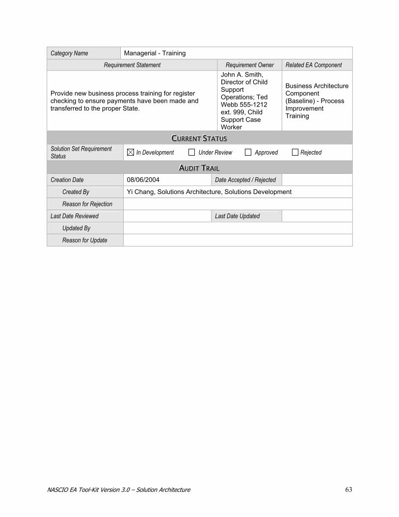
NASCIO EA Tool-Kit Version 3.0 – Solution Architecture 63
Category Name Managerial - Training
Requirement Statement Requirement Owner Related EA Component
Provide new business process training for register checking to ensure payments have been made and transferred to the proper State.
John A. Smith, Director of Child Support Operations; Ted Webb 555-1212 ext. 999, Child Support Case Worker
Business Architecture Component (Baseline) - Process Improvement Training
CCCUUURRRRRREEENNNTTT SSSTTTAAATTTUUUSSS Solution Set Requirement Status In Development Under Review Approved Rejected
AAAUUUDDDIIITTT TTTRRRAAAIIILLL Creation Date 08/06/2004 Date Accepted / Rejected
Created By Yi Chang, Solutions Architecture, Solutions Development
Reason for Rejection
Last Date Reviewed Last Date Updated
Updated By
Reason for Update

NASCIO EA Tool-Kit Version 3.0 – Solution Architecture 64
SSSooollluuutttiiiooonnn SSSeeettt DDDeeesssiiigggnnn
DDDEEEFFFIIINNNIIITTTIIIOOONNN Name Child Support Payments to Other States (ACH) – Solution Set Design
KKKEEEYYYWWWOOORRRDDDSSS
Keywords / Aliases Child Support Payments; Non-custodial Parent; Custodial Parent; Out-of-State, ADC
SSSOOOLLLUUUTTTIIIOOONNN SSSEEETTT TTTYYYPPPEEE Type of Solution Business Application IT Infrastructure
DDDEEESSSIIIGGGNNN VVVIIIEEEWWW Design View Name Application
Category Name Functionality
Design Specification Related EA Component
Create transaction database table with appropriate record detail.
TA Compliance Component – Database Standards-Batch Record Update
Related Requirements Relationship
Create out-of-State transaction (with transaction detail) for sending to other States.
Satisfies Requirement
Create transmission file in proper format for bank. Satisfies Requirement
Data in transmission file are 100% accurate (Note: Transmission is delivered in format and content as originators specified. Accuracy of data cannot be controlled)
Technically Satisfied; However, cannot control data accuracy.
DDDEEESSSIIIGGGNNN VVVIIIEEEWWW Design View Name Usability
Category Name GUI
Design Specifications Related EA Component Assemble payments by Case Worker ID and display for review on their workstation.
EA Component Needed.
Adhoc query by caseworker number will produce information to be displayed by browser.
TA Product Component-Crystal Reports
Related Requirements Relationship Viewing of specific caseworker payments viewable via standard browser interface.
Satisfies Requirement
Query information based on individual case worker ID number Satisfies Requirement

NASCIO EA Tool-Kit Version 3.0 – Solution Architecture 65
DDDEEESSSIIIGGGNNN VVVIIIEEEWWW Design View Name Business
Category Business Cycle
Design Specifications Related EA Component
Received payments need to be available to Case Workers after end of month processing
IA Process Component-Batch Processing
Related Requirements Relationship
Submit out-Of-State transaction database update job after completion of month-end payment processing batch job.
Satisfies Requirement - Business Rule
DDDEEESSSIIIGGGNNN VVVIIIEEEWWW Design View Name Security
Category Technical
Design Specifications Related EA Component
Transmission file data must be sent with 128 encryption standards. TA Compliance Component - SSL Encryption Standards
Related Requirements Relationship
SSL Encryption Standards Satisfies Requirement
DDDEEESSSIIIGGGNNN VVVIIIEEEWWW Design View Name Integration
Category Technical - Accuracy
Design Specification Related EA Component
Query Family Court related database to determine status of Court order. TA Compliance Component —Database Queries
Related Requirements Relationship Transmit only payments that are still in effect per the custodial parent Court orders.
Satisfies Requirement
Update system upon successful receipt of payments from out-of-State agency. Satisfies Requirement
DDDEEESSSIIIGGGNNN VVVIIIEEEWWW Design View Name Integration
Category Technical - Capacity
Design Specification Related EA Component
Impact Statement---Coordinate with Capacity Planning team to ensure adequate space is available
* Operational Impact - Planning of DASD Space
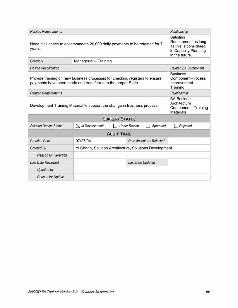
NASCIO EA Tool-Kit Version 3.0 – Solution Architecture 66
Related Requirements Relationship
Need disk space to accommodate 20,000 daily payments to be retained for 7 years.
Satisfies Requirement as long as this is considered in Capacity Planning in the future.
Category Managerial – Training
Design Specification Related EA Component
Provide training on new business processes for checking registers to ensure payments have been made and transferred to the proper State
Business Component-Process Improvement Training
Related Requirements Relationship
Development Training Material to support the change in Business process
BA Business Architecture Component - Training Materials
CCCUUURRRRRREEENNNTTT SSSTTTAAATTTUUUSSS Solution Design Status In Development Under Review Approved Rejected
AAAUUUDDDIIITTT TTTRRRAAAIIILLL Creation Date 07/27/04 Date Accepted / Rejected
Created By Yi Chang, Solution Architecture, Solutions Development
Reason for Rejection
Last Date Reviewed Last Date Updated
Updated by
Reason for Update

NASCIO EA Tool-Kit Version 3.0 – Solution Architecture 67
SSSooollluuutttiiiooonnn SSSeeettt SSScccooopppeee
A Solution Project: Enterprise GIS Clearinghouse
DDDEEEFFFIIINNNIIITTTIIIOOONNN Name Enterprise GIS Clearinghouse – Solution Set Scope
Description
Currently GIS systems exist in several State agencies and numerous local government entities. These are usually very specialized databases and applications for the agencies and entities that use them. At no time in the past has there been a collection of GeoSpatial data in one database that covers many GIS layers. The Enterprise GIS Clearinghouse will be such a collection of data. The Clearinghouse will reside in the State Data Center and will host, at a minimum, the Mississippi Digital Earth Model (MDEM) which includes the following core data layers of a digital land base computer model of the State of Mississippi on a Statewide basis:
Geodetic Control Elevation and Bathymetry Orthoimagery Hydrography Transportation Government Boundaries Cadastral
In addition, the clearinghouse will contain other geospatial data and applications to access data as determined by the GIS Council, Policy Advisory Committee, Technical Users’ Committee and Clearinghouse staff.
Rationale
During the 2003 legislative session, legislation was passed that created a Council on Remote Sensing and GIS. That legislation directed that the Department of Information Technology Services would host an Enterprise GIS Clearinghouse that contains the MDEM and other data of interest to citizens, businesses, and State and local governments.
Benefits Provides a single source for accessing and retrieving Geospatial data that is available to all along with applications that will supply users with various ways of looking at the data.
BBBOOOUUUNNNDDDAAARRRYYY
Boundary Scope Statement
Provides a single source for accessing and retrieving Geospatial data that is available to all users in addition to applications that will supply users with various ways of looking at the data. All Clearinghouse applications and data will be accessed through the GIS Portal.

NASCIO EA Tool-Kit Version 3.0 – Solution Architecture 68
AAASSSSSSOOOCCCIIIAAATTTEEEDDD IIIMMMPPPLLLEEEMMMEEENNNTTTAAATTTIIIOOONNN PPPLLLAAANNN IIITTTEEEMMMSSS Implementation Plan Project Identifier 05ITS001; Planning and Implementation of a Enterprise GIS Clearinghouse
Plan Items Upon Which the Solution Set is Dependant
05DEQ01; Funding for, Purchasing, and QA of initial clearinghouse data 05ITS02; Funding for ITS GIS Infrastructure
Plan Items Dependant Upon Solution Set N/A
Related Migration Strategies Strategy for Determining Effect of GIS Clearinghouse on Statewide Network Selected Solution Set Conceptual Model Enterprise GIS Clearinghouse: Conceptual Model.doc within EA
Solution Set Types Business Application IT Infrastructure
KKKEEEYYYWWWOOORRRDDDSSS Keywords / Aliases GIS; Geographic Information Systems; Geospatial; Clearinghouse; Warehouse;
Data;
CCCOOONNNTTTAAACCCTTT IIINNNFFFOOORRRMMMAAATTTIIIOOONNN Project Sponsor David Litchliter, CIO, Mississippi Department of Information Technology Services;
Charles Chism, CEO, Mississippi Department of Environmental Quality Implementation Plan Coordinator
Claude Johnson, Strategic Services Director, Mississippi Department of Information Technology Services
Solution Set Architect Craig Orgeron, Architect, Mississippi Department of Information Technology Services
Solution Set Contributors
Cragin Knox 555-1212, Department of Environmental Quality Jim Steil 555-1212, MARIS David Rankin, 555-1212, Warren County Terry Bergin, 555-1212, Department of Information Technology Services
CCCOOONNNTTTRRRAAACCCTTT IIINNNFFFOOORRRMMMAAATTTIIIOOONNN Name There are no additional contractual requirements for this project
Reference Number
Contact Information
Implications
CCCUUURRRRRREEENNNTTT SSSTTTAAATTTUUUSSS Solution Set Scope Status In Development Under Review Approved Rejected
AAAUUUDDDIIITTT TTTRRRAAAIIILLL Creation Date 08/17/2004 Date Accepted / Rejected
Created By Claude Johnson, Director Strategic Services
Reason for Rejection
Last Date Reviewed Last Date Updated
Updated By
Reason for Update

NASCIO EA Tool-Kit Version 3.0 – Solution Architecture 69
SSSooollluuutttiiiooonnn SSSeeettt RRReeeqqquuuiiirrreeemmmeeennntttsss
DDDEEEFFFIIINNNIIITTTIIIOOONNN Name Enterprise GIS Clearinghouse and Portal – Solution Set Requirements
Description
Currently GIS systems exist in several State agencies and numerous local government entities. These are usually very specialized databases and applications for the agencies and entities that use them. At no time in the past has there been a collection of GeoSpatial data in one database that covers many GIS layers. The Enterprise GIS Clearinghouse will be such a collection of data. The Clearinghouse will reside in the State Data Center and will host, at a minimum, the Mississippi Digital Earth Model (MDEM) which includes the following core data layers of a digital land base computer model of the State of Mississippi on a Statewide basis:
Geodetic Control Elevation and Bathymetry Orthoimagery Hydrography Transportation Government Boundaries Cadastral
In addition, the clearinghouse will contain other geospatial data and applications to access data as determined by the GIS Council, Policy Advisory Committee, Technical Users’ Committee and Clearinghouse staff.
Rationale
During the 2003 legislative session, legislation was passed that create a Council on Remote Sensing and GIS. That legislation directed that the Department of Information Technology Services would host an Enterprise GIS Clearinghouse that contains the MDEM and other data of interest to citizens, businesses, and State and local governments.
Benefits Provides a single source for accessing and retrieving Geospatial data that is available to all, along with applications that will supply users with various ways of looking at the data.
BBBOOOUUUNNNDDDAAARRRYYY
Boundary Limit Statement
Provides a single source for accessing and retrieving Geospatial data that is available to all users in addition to applications that will supply users with various ways of looking at the data. All Clearinghouse applications and data will be accessed through the GIS Portal.
KKKEEEYYYWWWOOORRRDDDSSS Keywords / Aliases GIS; Geographic Information Systems; Geospatial; Clearinghouse;
Warehouse; Data;
SSSOOOLLLUUUTTTIIIOOONNN SSSEEETTT TTTYYYPPPEEE Type of Solution Business Application IT Infrastructure
RRREEEQQQUUUIIIRRREEEMMMEEENNNTTTSSS VVVIIIEEEWWW Requirements View Name Enterprise GIS Clearinghouse and Portal
View Category Infrastructure; Information
Requirement Statement Requirement Owner Related EA Component
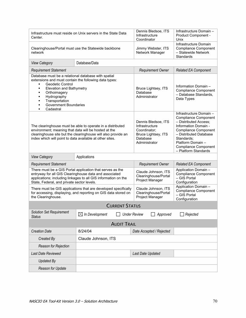
NASCIO EA Tool-Kit Version 3.0 – Solution Architecture 70
Infrastructure must reside on Unix servers in the State Data Center.
Dennis Bledsoe, ITS Infrastructure Coordinator
Infrastructure Domain – Product Component - Unix
Clearinghouse/Portal must use the Statewide backbone network
Jimmy Webster, ITS Network Manager
Infrastructure Domain Compliance Component – Statewide Network Standards
View Category Database/Data
Requirement Statement Requirement Owner Related EA Component Database must be a relational database with spatial extensions and must contain the following data types:
Geodetic Control Elevation and Bathymetry Orthoimagery Hydrography Transportation Government Boundaries Cadastral
Bruce Lightsey, ITS Database Administrator
Information Domain – Compliance Component – Database Standards, Data Types
The clearinghouse must be able to operate in a distributed environment; meaning that data will be hosted at the clearinghouse site but the clearinghouse will also provide an index which will point to data available at other sites.
Dennis Bledsoe, ITS Infrastructure Coordinator; Bruce Lightsey, ITS Database Administrator
Infrastructure Domain – Compliance Component – Distributed Access; Information Domain - Compliance Component – Distributed Database Standards; Platform Domain – Compliance Component – Platform Standards
View Category Applications
Requirement Statement Requirement Owner Related EA Component There must be a GIS Portal application that serves as the entryway for all GIS Clearinghouse data and associated applications; including linkages to all GIS information on the State, Federal, and private sector levels.
Claude Johnson, ITS Clearinghouse/Portal Project Manager
Application Domain – Compliance Component – GIS Portal Configuration
There must be GIS applications that are developed specifically for accessing, displaying, and reporting on GIS data stored on the Clearinghouse.
Claude Johnson, ITS Clearinghouse/Portal Project Manager
Application Domain – Compliance Component – GIS Portal Configuration
CCCUUURRRRRREEENNNTTT SSSTTTAAATTTUUUSSS Solution Set Requirement Status In Development Under Review Approved Rejected
AAAUUUDDDIIITTT TTTRRRAAAIIILLL Creation Date 8/24/04 Date Accepted / Rejected
Created By Claude Johnson, ITS
Reason for Rejection
Last Date Reviewed Last Date Updated
Updated By
Reason for Update
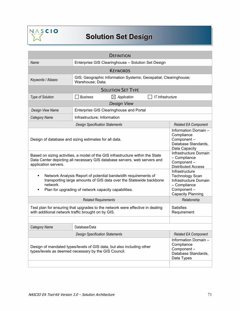
NASCIO EA Tool-Kit Version 3.0 – Solution Architecture 71
SSSooollluuutttiiiooonnn SSSeeettt DDDeeesssiiigggnnn
DDDEEEFFFIIINNNIIITTTIIIOOONNN Name Enterprise GIS Clearinghouse – Solution Set Design
KKKEEEYYYWWWOOORRRDDDSSS Keywords / Aliases GIS; Geographic Information Systems; Geospatial; Clearinghouse;
Warehouse; Data;
SSSOOOLLLUUUTTTIIIOOONNN SSSEEETTT TTTYYYPPPEEE Type of Solution Business Application IT Infrastructure
Design View Design View Name Enterprise GIS Clearinghouse and Portal
Category Name Infrastructure; Information
Design Specification Statements Related EA Component
Design of database and sizing estimates for all data.
Information Domain – Compliance Component – Database Standards, Data Capacity
Based on sizing activities, a model of the GIS infrastructure within the State Data Center depicting all necessary GIS database servers, web servers and application servers.
Infrastructure Domain – Compliance Component – Distributed Access
Network Analysis Report of potential bandwidth requirements of transporting large amounts of GIS data over the Statewide backbone network.
Plan for upgrading of network capacity capabilities.
Infrastructure Technology Scan Infrastructure Domain – Compliance Component – Capacity Planning
Related Requirements Relationship
Test plan for ensuring that upgrades to the network were effective in dealing with additional network traffic brought on by GIS.
Satisfies Requirement
Category Name Database/Data
Design Specification Statements Related EA Component
Design of mandated types/levels of GIS data, but also including other types/levels as deemed necessary by the GIS Council.
Information Domain – Compliance Component – Database Standards, Data Types

NASCIO EA Tool-Kit Version 3.0 – Solution Architecture 72
Related Requirements Relationship
GIS Council approval of database/data design. Satisfies Requirement
Department of Environmental Quality must have produced and QA’d the data prior to implementation of data on the Clearinghouse. Satisfies Mandate
Category Name Applications
Design Specification Statement Related EA Component
Design of the GIS Portal must fit Web design standards.
Application Domain – Compliance Component – Web Portal Design Standards
Design of GIS Clearinghouse applications must meet Web application design standards.
Application Domain – Compliance Component – Web Application Design Standards
Related Requirements Relationship
GIS Council approval of GIS Portal Satisfies Requirement
GIS Council approval of GIS Clearinghouse applications Satisfies Requirement
SSSOOOLLLUUUTTTIIIOOONNN SSSEEETTT LLLOOOGGGIIICCCAAALLL MMMOOODDDEEELLL Source Document GIS Clearinghouse and Portal Logical Design (not yet completed) Refer to
the Enterprise GIS Clearinghouse: Conceptual Model.doc within EA
CCCUUURRRRRREEENNNTTT SSSTTTAAATTTUUUSSS Solution Set Design Status In Development Under Review Approved Rejected
AAAUUUDDDIIITTT TTTRRRAAAIIILLL Creation Date 8/24/04 Date Accepted / Rejected
Created By Claude Johnson, ITS
Reason for Rejection
Last Date Reviewed Last Date Updated
Updated by
Reason for Update

NASCIO EA Tool-Kit Version 3.0 – Solution Architecture 73
SSSooollluuutttiiiooonnn SSSeeettt SSScccooopppeee
Project: e-Forms
DDDEEEFFFIIINNNIIITTTIIIOOONNN Name E-Forms - Solution Set Scope
Description
Currently, the majority of State forms are available on the State’s Website in a non-enterable format. They have to be printed, filled in, and either faxed or mailed in to the appropriate agency. This is true both for forms used by the public and for forms used internally. The capability to be able to fill out and submit a form on-line would have tremendous value.
Rationale This solution directly supports the State’s efforts to make it easier to do business with all agencies of the State and to become more efficient and effective with our internal processes.
Benefits
For the public, the information on any e-form is sent directly to the agency without faxing or mailing, resulting in a more efficient and speedy process. In addition, all required information and appropriate formats are assured at the time the form is filled resulting in a decrease of issues related incomplete or incorrect forms being submitted. This can result in fewer delays in service delivery and an increase in customer satisfaction. The State will benefit by having information collected within the form available directly after its entry.
BBBOOOUUUNNNDDDAAARRRYYY
Boundary Scope Statement
This solution will not initially integrate with the existing digital signature capability. The information gathered on the form will be available to be directly entered into existing processes and databases without any re-entry of data or editing. Solution will need to allow the State Commission on Public Records to approve every new form that is made available on the State Website
AAASSSSSSOOOCCCIIIAAATTTEEEDDD IIIMMMPPPLLLEEEMMMEEENNNTTTAAATTTIIIOOONNN PPPLLLAAANNN IIITTTEEEMMMSSS Implementation Plan Project Identifier ITOC 010; e-Forms
Plan Items Upon Which the Solution Set is Dependant
ITOC 011; e-Forms Routing
Plan Items Dependant Upon Solution Set N/A
Related Migration Strategies N/A
Selected Solution Set Conceptual Model e-Forms flow diagram(Visio); shared drive under IT Architecture Models

NASCIO EA Tool-Kit Version 3.0 – Solution Architecture 74
Solution Set Type Application Solution
KKKEEEYYYWWWOOORRRDDDSSS Keywords / Aliases Fill-able PDF; on-line forms; (Form Titles i.e. Request for Birth Certificate, etc)
CCCOOONNNTTTAAACCCTTT IIINNNFFFOOORRRMMMAAATTTIIIOOONNN Project Sponsor Sean Fahey, Director, INTELENET Implementation Plan Coordinator Andy Miller, Director, accessIndiana
Solution Set Architect Randy Grimes, Architect, accessIndiana
Solution Set Contributors
Connie Hume, Commission on Public Records, 317/232-5555 Chris Pichereau, Director, DoIT; 317/232-5556 Jake Moelk, Systems Consultant, ITOC; 317/232-5557 Paul Tex, Manager, DoIT; 317/232-5558 Jim Hussey, Business Consultant, DoIT; 317/232-5559
CCCOOONNNTTTRRRAAACCCTTT IIINNNFFFOOORRRMMMAAATTTIIIOOONNN Name Forms Fill-in Vendor
Reference Number FF-2367A
Contact Information Connie Hume, Commission on Public Records, 317/232-5555; Forms Fill-in Vendor Representative, 317/555-1212
Implications Failure will mean we do not make our efficiency and effectiveness goals
CCCUUURRRRRREEENNNTTT SSSTTTAAATTTUUUSSS Solution Set Status In Development Under Review Approved Rejected
AAAUUUDDDIIITTT TTTRRRAAAIIILLL Creation Date 1/2/02 Date Accepted / Rejected 6/1/04
Created By Jake Moelk, Systems Consultant, ITOC; 317/232-5557 Reason for Rejection
Last Date Reviewed Last Date Updated
Updated By
Reason for Update
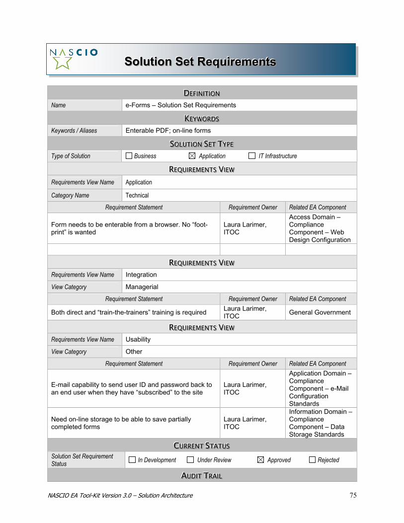
NASCIO EA Tool-Kit Version 3.0 – Solution Architecture 75
SSSooollluuutttiiiooonnn SSSeeettt RRReeeqqquuuiiirrreeemmmeeennntttsss
DDDEEEFFFIIINNNIIITTTIIIOOONNN Name e-Forms – Solution Set Requirements
KKKEEEYYYWWWOOORRRDDDSSS Keywords / Aliases Enterable PDF; on-line forms
SSSOOOLLLUUUTTTIIIOOONNN SSSEEETTT TTTYYYPPPEEE Type of Solution Business Application IT Infrastructure
RRREEEQQQUUUIIIRRREEEMMMEEENNNTTTSSS VVVIIIEEEWWW Requirements View Name Application
Category Name Technical
Requirement Statement Requirement Owner Related EA Component
Form needs to be enterable from a browser. No “foot-print” is wanted
Laura Larimer, ITOC
Access Domain – Compliance Component – Web Design Configuration
RRREEEQQQUUUIIIRRREEEMMMEEENNNTTTSSS VVVIIIEEEWWW Requirements View Name Integration
View Category Managerial
Requirement Statement Requirement Owner Related EA Component
Both direct and “train-the-trainers” training is required Laura Larimer, ITOC General Government
RRREEEQQQUUUIIIRRREEEMMMEEENNNTTTSSS VVVIIIEEEWWW Requirements View Name Usability
View Category Other
Requirement Statement Requirement Owner Related EA Component
E-mail capability to send user ID and password back to an end user when they have “subscribed” to the site
Laura Larimer, ITOC
Application Domain – Compliance Component – e-Mail Configuration Standards
Need on-line storage to be able to save partially completed forms
Laura Larimer, ITOC
Information Domain – Compliance Component – Data Storage Standards
CCCUUURRRRRREEENNNTTT SSSTTTAAATTTUUUSSS Solution Set Requirement Status In Development Under Review Approved Rejected
AAAUUUDDDIIITTT TTTRRRAAAIIILLL

NASCIO EA Tool-Kit Version 3.0 – Solution Architecture 76
Creation Date 1/2/04 Date Accepted / Rejected 6/1/04
Created By Jake Moelk, Systems Consultant, ITOC
Reason for Rejection
Last Date Reviewed Last Date Updated
Updated By
Reason for Update
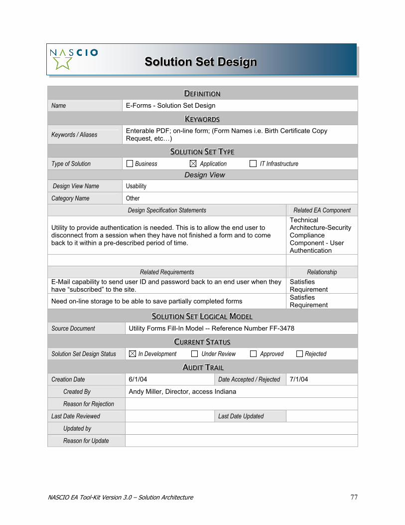
NASCIO EA Tool-Kit Version 3.0 – Solution Architecture 77
SSSooollluuutttiiiooonnn SSSeeettt DDDeeesssiiigggnnn
DDDEEEFFFIIINNNIIITTTIIIOOONNN Name E-Forms - Solution Set Design
KKKEEEYYYWWWOOORRRDDDSSS Keywords / Aliases Enterable PDF; on-line form; (Form Names i.e. Birth Certificate Copy
Request, etc…)
SSSOOOLLLUUUTTTIIIOOONNN SSSEEETTT TTTYYYPPPEEE Type of Solution Business Application IT Infrastructure
Design View Design View Name Usability
Category Name Other
Design Specification Statements Related EA Component
Utility to provide authentication is needed. This is to allow the end user to disconnect from a session when they have not finished a form and to come back to it within a pre-described period of time.
Technical Architecture-Security Compliance Component - User Authentication
Related Requirements Relationship E-Mail capability to send user ID and password back to an end user when they have “subscribed” to the site.
Satisfies Requirement
Need on-line storage to be able to save partially completed forms Satisfies Requirement
SSSOOOLLLUUUTTTIIIOOONNN SSSEEETTT LLLOOOGGGIIICCCAAALLL MMMOOODDDEEELLL Source Document Utility Forms Fill-In Model -- Reference Number FF-3478
CCCUUURRRRRREEENNNTTT SSSTTTAAATTTUUUSSS Solution Set Design Status In Development Under Review Approved Rejected
AAAUUUDDDIIITTT TTTRRRAAAIIILLL Creation Date 6/1/04 Date Accepted / Rejected 7/1/04
Created By Andy Miller, Director, access Indiana
Reason for Rejection
Last Date Reviewed Last Date Updated
Updated by
Reason for Update
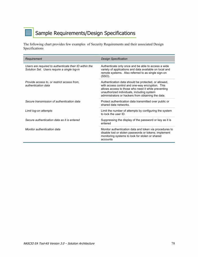
NASCIO EA Tool-Kit Version 3.0 – Solution Architecture 78
Sample Requirements/Design Specifications The following chart provides few examples of Security Requirements and their associated Design Specifications
Requirement Design Specification
Users are required to authenticate their ID within the Solution Set. Users require a single log-in
Authenticate only once and be able to access a wide variety of applications and data available on local and remote systems. Also referred to as single sign-on (SSO).
Provide access to, or restrict access from, authentication data
Authentication data should be protected, or allowed, with access control and one-way encryption. This allows access to those who need it while preventing unauthorized individuals, including system administrators or hackers from obtaining the data.
Secure transmission of authentication data Protect authentication data transmitted over public or shared data networks.
Limit log-on attempts Limit the number of attempts by configuring the system to lock the user ID.
Secure authentication data as it is entered Suppressing the display of the password or key as it is entered
Monitor authentication data Monitor authentication data and token via procedures to disable lost or stolen passwords or tokens; implement monitoring systems to look for stolen or shared accounts
NASCIO EA Tool-Kit Version 3.0 – Solution Architecture 79
SUMMARY/CONCLUSION
The Solution Architecture provides a framework for capturing requirements and design specifications that are necessary for developing integrated enterprise solutions. Solution Architecture establishes a critical link between Business Architecture, Information Architecture, and Technology Architecture. Solution Architecture brings all these components together and enables the solution architect to leverage all the architecture artifacts to design integrated, enterprise-wide, reusable solutions. It is through the pursuit of a formal Solution Architecture that the following are provided:
• A demonstrable, repeatable approach to assuring solutions are designed from an integrated perspective and based on the stated future architectural direction of the enterprise
• Identification of opportunities to leverage linkage across government-wide entities and increase collaboration and sharing of systems and solutions
• A means to increase architecture re-use and reduce the development of point solutions throughout the enterprise.
State and local government entities use Solution Architecture to provide clarity and direction for designing an integrated set of solutions, based on the overall business, information, and technology goals of the organization.
NASCIO EA Tool-Kit Version 3.0 – Solution Architecture 80
NASCIO Online Visit NASCIO on the web for the latest information
on the Architecture Program or to download the current version of the Enterprise Architecture
Development Tool-Kit.
www.nascio.org