nasa electronic parts and packaging (nepp) … 11, 2013 · nasa electronic parts and packaging...
TRANSCRIPT

www.nasa.gov
NASA Electronic Parts and Packaging (NEPP) Hermeticity Task Overview
NEPP Program Task 13-294: Hermeticity Correlation Study
NASA MSFC/GSFC ES43 / Patrick McManus ES43-ERC / Kathy Pressnell GSFC-5620 / Lyudmyla Panashchenko
June 11, 2013

2
AGENDA
I. Introduction
II. Overview of Hermeticity
III. Hermeticity Correlation Study
A. Helium Desorption Issue
B. Instrument Correlation Study
C. Leak Standard Development
D. Test Method Optimization
IV. Future Work

3
INTRODUCTION Hermeticity task is a collaborative effort between GSFC/MSFC to address the following:
• Gain understanding of the influence of component part material on resultant leak rate data
• Determine CHLD test equipment capability between NASA centers as well as correlation of test results with other equipment used for hermeticity testing (OLT, Krypton-85, IGA)
• Design, fabricate, and test gross leak hermeticity standards
• Provide input to DLA Land & Maritime to optimize hermeticity specifications based on the knowledge gained during correlation study, part testing, and research efforts

4
OVERVIEW
“Why, When, How, and What” Of Hermeticity Testing
• Fine and gross leak testing is used to determine the effectiveness of package seals in microelectronic packages. Damaged or defective seals and feedthroughs allow ambient air/water vapor to enter the internal cavity of the device which can result in internal corrosion leading to device failures.
• Testing may be performed just after sealing process, but usually performed during screening/qualification. Sometimes performed as part of a DPA or failure analysis.
• Testing is performed in accordance with MIL-STD-883, Test Method 1014 for hybrids/microcircuits and MIL-STD-750 for 1071 for discrete semiconductor devices
• Three systems are used to non-destructively test: CHLD, KR-85, OLT • CHLD, Kr-85 systems use back pressurization of a tracer gas to enter existing
leak paths. A detector is used to determine the presence of gas. • OLT uses a pressurization technique which causes lid deflection if the device
is non-hermetic

5
OVERVIEW
What is a Failure? Two Failure Classifications • Screening/Qualification Failures: Hermeticity and IGA Testing
• Helps manufacturers validate process is operating nominally • Prevents non-conforming product from entering the supply chain • Identifies lots that may have potential latent defects (IGA)
• Test/Field Failures • Hard electrical failures identified during system level testing or during the
mission • Cost and scheduling impacts or in worst case scenario loss of mission
Are the test methods in MIL Specs adequate? • Recent evidence verified non-hermetic parts are being shipped
• A DoD analysis of program data identified Class K hybrid failures which had passed MIL-STD-883 hermeticity screening requirements yet failed IGA during investigation.
• Example 1 - One hybrid lot was rescreened to tighter leak rates of MIL-STD-750 : 23 of the108 parts tested failed
• Example 2 - Vehicle level electrical field failure: 3 yrs 1st functional failure at system level with 2 additional failures within 6 months.
6
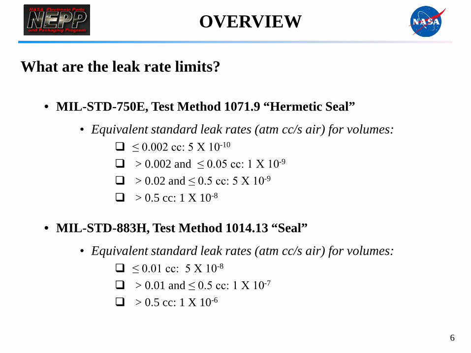
OVERVIEW What are the leak rate limits?
• MIL-STD-750E, Test Method 1071.9 “Hermetic Seal”
• Equivalent standard leak rates (atm cc/s air) for volumes: ≤ 0.002 cc: 5 X 10⁻¹⁰ > 0.002 and ≤ 0.05 cc: 1 X 10⁻⁹ > 0.02 and ≤ 0.5 cc: 5 X 10⁻⁹
> 0.5 cc: 1 X 10⁻⁸
• MIL-STD-883H, Test Method 1014.13 “Seal”
• Equivalent standard leak rates (atm cc/s air) for volumes: ≤ 0.01 cc: 5 X 10⁻⁸ > 0.01 and ≤ 0.5 cc: 1 X 10⁻⁷
> 0.5 cc: 1 X 10⁻⁶

7
OVERVIEW How do we determine optimum leak rate requirements?

8
OVERVIEW How do we determine optimum leak rate requirements?

9
Hermiticity Correlation Study What is the purpose of this study?
NEPP funded the Hermeticity Correlation Task to determine test equipment capability and focus on optimizing both MIL-STD-750 and MIL-STD-883 test methods based on findings from our research and testing.
Krypton-85 (IsoVac Mark V Bomb Station)
CHLD (Pernicka 700H System)
OLT System (NorCom 2020 Optical Leak Test System)

10
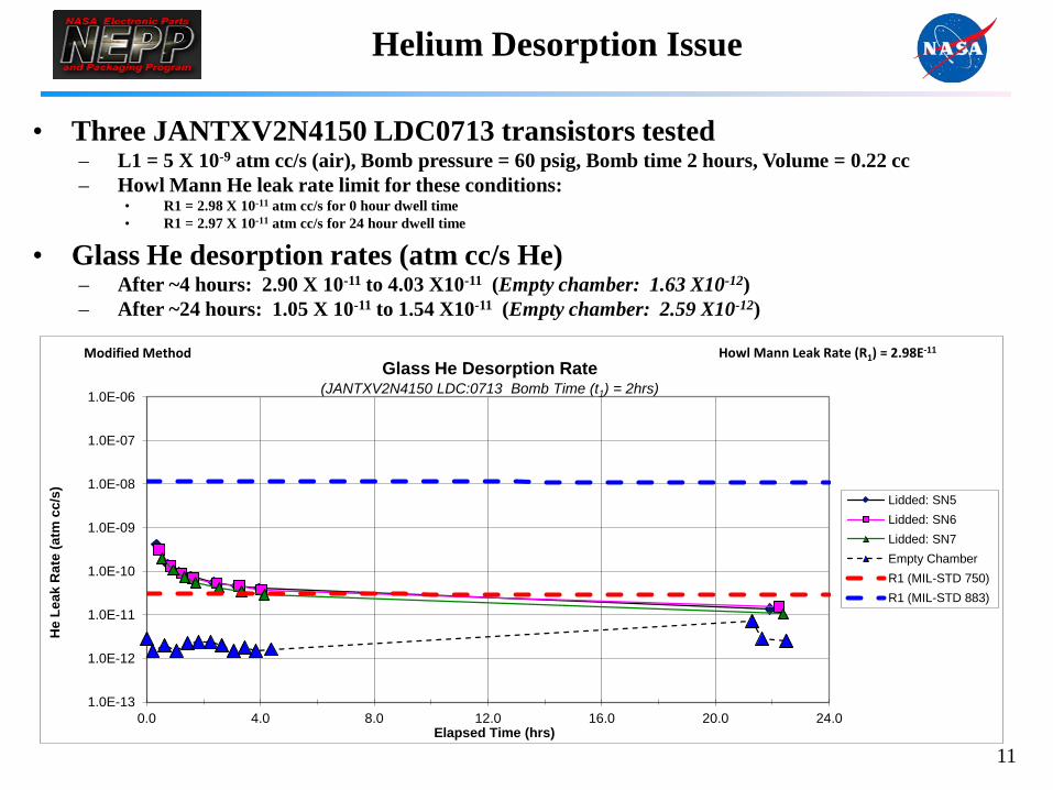
Helium Desorption Issue
Objective • Gain understanding of the influence of component part material on resultant
leak rate data
Issue • MSFC purchased a CHLD system in 2008 that has the sensitivity to test to
the tightened fine leak rate requirements of MIL-STD-750.
• MSFC discovered that glass feedthroughs exhibit different levels of surface desorption after He bombing resulting in false failures not evident prior to tightening.
• Therefore MSFC developed a method to characterize devices for desorption which allows the establishment of optimum bombing conditions while taking into consideration CHLD instrument sensitivity.
• As written the test method is inadequate to address this issue. MSFC will propose this change in the next revision.
11
Helium Desorption Issue
• Three JANTXV2N4150 LDC0713 transistors tested
– L1 = 5 X 10⁻⁹ atm cc/s (air), Bomb pressure = 60 psig, Bomb time 2 hours, Volume = 0.22 cc – Howl Mann He leak rate limit for these conditions:
• R1 = 2.98 X 10⁻¹¹ atm cc/s for 0 hour dwell time • R1 = 2.97 X 10⁻¹¹ atm cc/s for 24 hour dwell time
• Glass He desorption rates (atm cc/s He) – After ~4 hours: 2.90 X 10⁻¹¹ to 4.03 X10⁻¹¹ (Empty chamber: 1.63 X10⁻¹²) – After ~24 hours: 1.05 X 10⁻¹¹ to 1.54 X10⁻¹¹ (Empty chamber: 2.59 X10⁻¹²)
1.0E-13
1.0E-12
1.0E-11
1.0E-10
1.0E-09
1.0E-08
1.0E-07
1.0E-06
0.0 4.0 8.0 12.0 16.0 20.0 24.0
He
Leak
Rat
e (a
tm c
c/s)
Elapsed Time (hrs)
Glass He Desorption Rate (JANTXV2N4150 LDC:0713 Bomb Time (t1) = 2hrs)
Lidded: SN5 Lidded: SN6 Lidded: SN7 Empty Chamber R1 (MIL-STD 750) R1 (MIL-STD 883)
Howl Mann Leak Rate (R1) = 2.98E-11 Modified Method

12
Helium Desorption Issue
MSFC Characterization Method
Suggested bomb times are 0.5, 4, and 12 hours. Test devices in smallest chamber (with insert if necessary). Use batch test T-times for devices being tested and for all empty chamber tests. Lidded devices must be known good hermetically sealed devices. 1. Bomb 3 serialized lidded devices and 1 delidded device for selected bomb time. 2. Prior to bomb end time, run calibration and a minimum of three empty chamber tests. 3. Remove parts from bomb chamber. Note exact time parts are removed from bomb chamber. 4. Perform following test runs:
A. Empty chamber (1st empty chamber test should correspond with dwell time = 0) B. Delidded device C. Lidded device number 1 D. Lidded device number 2 E. Lidded device number 3
5. Repeat Step 4 continuously for four hours. Repeat Step 4 after 8 hours and 24 hours if the devices have not returned to empty chamber values. Calculate exact dwell time from the time stamp on the Excel leak table for each test run.
6. Plot measured helium leak rates of each device and empty chamber versus dwell time. 7. Plot R1 over test time. 8. Use all three charts (0.5, 4, and 12 hours) to determine optimum bomb time and dwell time parameters.

13
Helium Desorption Issue
1.0E-12
2.1E-11
4.1E-11
6.1E-11
8.1E-11
1.0E-10
1.2E-10
1.4E-10
1.6E-10
1.8E-10
2.0E-10
0.0 0.5 1.0 1.5 2.0 2.5 3.0 3.5 4.0
He
Leak
Rat
e (a
tm c
c/s)
Elapsed Time (hrs)
Glass He Desorption Rate (IR TO-39: Bomb Time (t1) = 4hrs)
Header: SN4
Lidded: SN18
Lidded: SN19
Lidded: SN20
R1
Empty
Howl Mann Leak Rate (R1) = 1.04E-10
(L=5.00E-9; Pe=74.7psia; V=0.126cc; t1=4hr) Method: 20/5/50/50/5 (Lidded Device)

14
Instrument Correlation Study Objective
• Determine CHLD test equipment capability between NASA centers as well as correlation of test results with other equipment used for hermeticity testing (OLT, Krypton-85, IGA)
Status • Confirmed GSFC/MSFC CHLD performance
• Used 2 calibrated helium leak standards to verify high/low leak range accuracy
• Verified empty chamber values to confirm analyzer sensitivity to detect fine leaks
• Performed GSFC/MSFC CHLD and OLT correlation study on 3 sets of MIL-STD-750 gross/fine leakers
• Started MSFC/IsoVac Kr85 correlation study on the same devices • Will perform IGA testing on devices for final confirmation and comparison • Planning a second instrument correlation study using MIL-STD-883 devices

15
Part System Tester a b c d e Results a b c d e Results
Set 1 Kr85 IsoVac 5/5 5/5
(TO-18) MSFC TBD TBD TBD TBD TBD
CHLD MSFC P P G P G 2/5 P P P P 1/5
0.0345 cc GSFC P P P P P 0/5 P P P 2/5
Kr85 (retest) IsoVac
OLT Norcom G P G 4/5 ? F F P 3/5
RGA ORS
Set 2 Kr85 IsoVac 5/5 5/5
(TO-5) MSFC
CHLD MSFC G G G 5/5 F F 5/5
0.2244 cc GSFC G 5/5 F F F F 5/5
Kr85 (retest) IsoVac
OLT Norcom P P P 2/5 P P P P 1/5
RGA ORS
Set 3 Kr85 IsoVac 5/5 5/5
(ceramic) MSFC
CHLD MSFC P P P P P 0/5 5/5
0.0026 cc GSFC P P P P P 0/5 F F F F 5/5
Kr85 (retest) IsoVac
OLT Norcom
RGA ORS
Notes:Green: Parts Failed and correlate with baseline Kr85 rejection resultsRed: Part Failed but failed gross when Kr85 failed them as fine (G) or failed fine when Kr85 failed them as gross (F)
Instrument not capable to test partsP: Indicates parts passed and do not correlate with baseline Kr85 data?: NorCom marked "no result"
Fine Gross
Instrument Correlation Study

16
Leak Standard Development Objective
• Design, fabricate, and test gross leak hermeticity standards
Issue • Traceable standards are not available to verify that all three test systems have
the capability to detect gross leaks
Status • MSFC finalized a design configuration of three package sizes. Standards are
being fabricated using typical manufacturing processes and are comprised of all metal components to minimize desorption.
• CHLD and Kr-85 testing will be performed on the as-received devices to ensure hermeticity.
• Collaborate with outside vendor to drill submicron size cylindrical holes to obtain standardized flow rates. Test using all three pieces of equipment.
• Patent research and obtain NIST certification

17
Test Method Optimization
Objective
• Provide input to DLA Land & Maritime to optimize hermeticity specifications based on the knowledge gained during correlation study, part testing, and research efforts
Status • Submitted essential comments to address the tightening of MIL-STD-883
leak rate limits and to clarify CHLD test procedures • Supported JC-13 Hermeticity Task Group 11-01 formed to investigate the
tightening of MIL-STD-883 limits • Will continue to provide comments to clarify test procedures based on
information gained from correlation study, standard development, and part testing

18
Test Method Optimization JC-13 Hermeticity Task Group 11-01
Objective • Crane Electronics chaired a task group to support the tightening of MIL-
STD-883 limits.
Synopsis • Crane Electronics identified a process control issue which resulted in an
investigation of a subset of 3000 hybrid microcircuit devices. The devices were originally tested to MIL-STD-883 leak limits and passed. The devices were retested to MIL-STD-750 and numerous failures were discovered.
• Crane requested MSFC to support the internal inspection of four samples that had failed hermeticity and exhibited electrical parametric shifts.
• MSFC found evidence of corrosion and ionic contamination.

Test Method Optimization
19
OPTICAL PHOTOGRAPHS
Evidence of corrosion along the edge and inside corner of the device lid
Sample M – Lid

Test Method Optimization
20
SEM IMAGES
Examination of corrosion area along the edge of the device lid
Darker areas indicate smaller molecular weight material typical of corrosion
products
Raised areas indicate corrosion
Sample M – Lid

Test Method Optimization
21
EDS SPECTRUM
Elemental analysis provides evidence of ionic contamination and corrosion
Sample M – Lid
Test Method Optimization
22
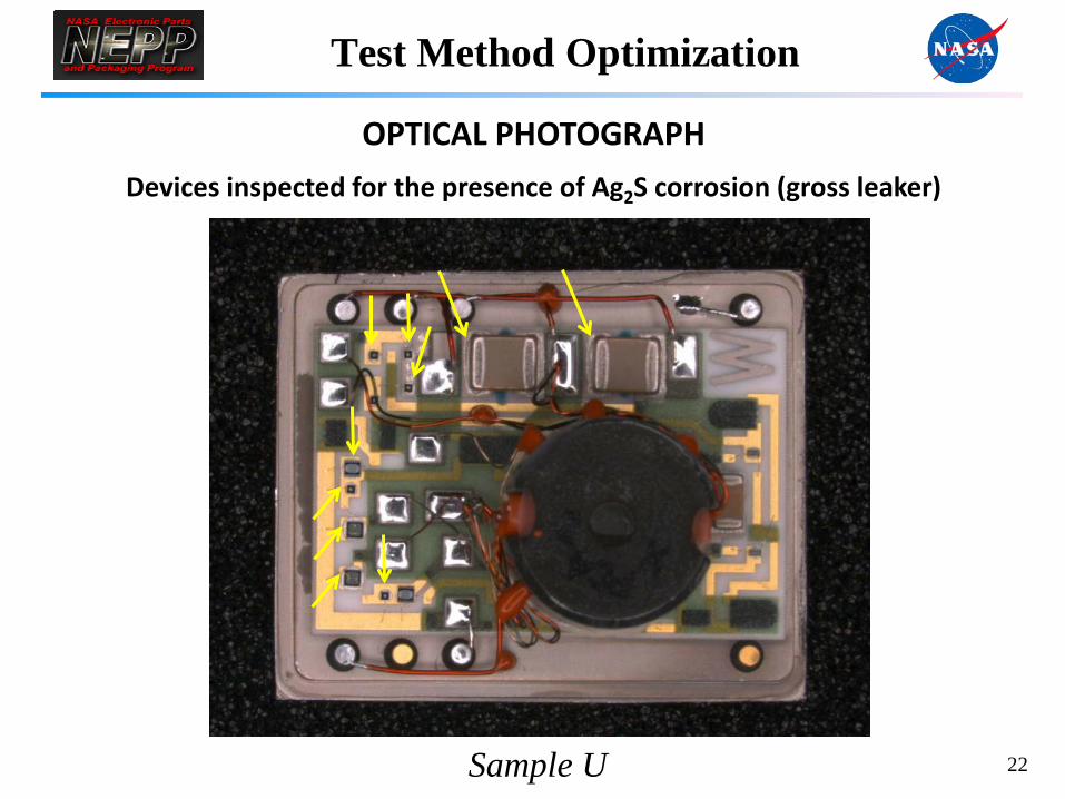
OPTICAL PHOTOGRAPH
Devices inspected for the presence of Ag2S corrosion (gross leaker)
Sample U

Test Method Optimization
23
SEM IMAGES
Examination of a representative Ag2S corrosion area
Die and bond area at low magnification Evidence of heavy growth of Ag2S along Ag die attach edge and bond pad
Sample U

Test Method Optimization
24
EDS SPECTRUM
Elemental analysis provides evidence of Ag2S corrosion
Sample U

Test Method Optimization
25
OPTICAL PHOTOGRAPHS
Device found with presence of Ag2S corrosion on top of passivation
Sample C

Test Method Optimization
26
SEM IMAGES
Examination of Ag2S corrosion area on top of passivation layer
Lighter area indicates a higher molecular weight material than silicon passivation
Shape of particles are consistent with silver die attach (arrows) and Ag2S corrosion
(circled)
Sample C

Test Method Optimization
27
EDS SPECTRUM Elemental analysis of materials on die surface
Spectrum of Ag die attach particles Spectrum of Ag2S corrosion
Sample C
Test Method Optimization
28
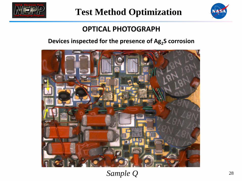
OPTICAL PHOTOGRAPH
Devices inspected for the presence of Ag2S corrosion
Sample Q

Test Method Optimization
29
SEM IMAGES
Examination of Ag2S corrosion on two diodes
Diode 1 shows light Ag2S corrosion forming on die attach
Diode 2 shows light Ag2S corrosion forming on board bond pad and die attach
Sample Q

Test Method Optimization
30
OPTICAL PHOTOGRAPH
Inspected devices for evidence of Ag2S corrosion
Control Sample

Test Method Optimization
31
SEM IMAGES
Examination for signs of corrosion
Inspection of stacked capacitor Ag die attach Inspection of a diode Ag die attach
Control Sample
Test Method Optimization
32
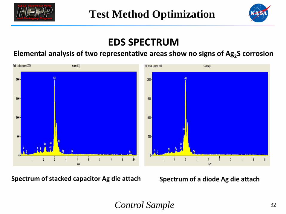
EDS SPECTRUM Elemental analysis of two representative areas show no signs of Ag2S corrosion
Spectrum of stacked capacitor Ag die attach Spectrum of a diode Ag die attach
Control Sample

33
Test Method Optimization
Control Sample:
• Passed MIL-STD-750 Kr85 leak tests and showed no evidence of corrosion
Suspect Devices:
• All devices showed evidence of corrosion • FeO2 is an oxidation reaction which occurs in the presence of moisture. • Ag2S is a reaction which occurs in the presence of H2S gas from the
atmosphere.
• All devices were Kr85 tested and found to be leakers • All devices fixed with Ag die attach showed evidence of Ag2S corrosion.
• Sample U was a gross leaker and showed heavier concentration of Ag2S.

34
Future Work
Helium and Kr85 Desorption Issue ♦ Research and document the influence of component part material on
resultant leak rate data
Instrument Correlation Study ♦ Complete Kr85 correlation study, perform IGA to quantitatively
determine constituent gas ratios and moisture content, and present findings
♦ Support a second instrument correlation study of MIL-STD-883 devices
Leak Standard Development ♦ Ensure hermeticity of fabricated devices, machine holes and obtain
standardized gross flow rates, and obtain leak rate data ♦ Conduct patent research and obtain NIST certification
Test Method Optimization ♦ Provide input to optimize specifications based on the knowledge gained
during correlation study, part testing, and research efforts

www.nasa.gov
NASA Electronic Parts and Packaging (NEPP) Hermeticity Task Overview
Questions?
June 11, 2013