nasa competition paper
TRANSCRIPT

1 Copyright © 2010 by “Team Pumpernickel”
2010 NASA Exploration Systems Mission Directorate:
Lunabotics Mining Competition Systems Engineering Paper
Team Pumpernickel:
Jameson Allen Colbert
Mark Palmer Keske
Dionel Ray Sylvester
Michael Lee Payne
Eddie Marshal Thomas
William Joseph Woodall
Faculty Advisors:
Dr. David Beale
Dr. Lloyd Stephen Riggs

2 Copyright © 2010 by “Team Pumpernickel”
ABSTRACT
A fast growing approach in determining the best
design concept for a problem is to hold a competition
in which the rules are based on requirements similar
to the actual problem. By going public with such
competitions, sponsoring entities receive some of the
most innovative engineering solutions in a fraction
of the time and cost it would have taken to develop
such concepts internally. Space exploration is a
large benefactor of such design competitions as seen
by the results of X-Prize Foundation and NASA
lunar excavation competitions [1].
The results of NASA’s past lunar excavator
challenges has led to the need for an effective means
of collecting lunar regolith in the absence of human
beings. The 2010 Exploration Systems Mission
Directorate (ESMD) Lunar Excavation Challenge
was created “to engage and retain students in
science, technology, engineering, and mathematics,
or STEM, in a competitive environment that may
result in innovative ideas and solutions, which could
be applied to actual lunar excavation for NASA.”
[2]. The ESMD Challenge calls for “teams to use
telerobotics or autonomous operations to excavate at
least 10kg of lunar regolith simulant in a 15 minute
time limit” [2].
The Systems Engineering approach was used in
accordance with Auburn University’s mechanical
engineering senior design course (MECH 4240-50)
to develop a telerobotic lunar excavator, seen in Fig.
1, that fulfilled requirements imposed by the NASA
ESMD Competition Rules. The goal of the senior
design project was to have a validated lunar
excavator that would be used in the NASA ESMD
lunar excavation challenge.
Figure 1: Excavator to date

3 Copyright © 2010 by “Team Pumpernickel”
Table of Contents
INTRODUCTION .............................................................................................................................................................. 5
SYSTEMS ENGINEERING............................................................................................................................................... 5
Mission Objective: .......................................................................................................................................................... 5
Mission Environment ...................................................................................................................................................... 5
System Requirements ...................................................................................................................................................... 5
Concepts of Operations ................................................................................................................................................... 6
Major Reviews: ............................................................................................................................................................... 6
Interfaces ......................................................................................................................................................................... 7
Architectural Design and Development: ......................................................................................................................... 7
Frame Subsystem: ........................................................................................................................................................... 7
Drive System: ................................................................................................................................................................ 10
Digger Arm: .................................................................................................................................................................. 13
Control Communication System: .................................................................................................................................. 16
Verification and Validation: .......................................................................................................................................... 18
Resource Budgets:......................................................................................................................................................... 19
Risk Management: ........................................................................................................................................................ 19
CONFIGURATION MANAGEMENT: ........................................................................................................................... 19
PROJECT MANAGEMENT: ........................................................................................................................................... 20
DELIVERABLES: ............................................................................................................................................................ 20
CONCLUSION: ................................................................................................................................................................ 20
REFERENCES: ................................................................................................................................................................ 21
APPENDIX A: Lunabotics Mining Competition Rules ................................................................................................... 22
APPENDIX B: Preliminary Design Review ..................................................................................................................... 27
APPENDIX C: Subsystem Interfaces ............................................................................................................................... 33
APPENDIX D: Decision Matrices .................................................................................................................................... 34
APPENDIX E: Bill of Materials ....................................................................................................................................... 35
APPENDIX F: Project Completion / Verification Check List .......................................................................................... 39
APPENDIX G: Technical Resource Budget ..................................................................................................................... 39
APPENDIX H: Risk Management .................................................................................................................................... 40

4 Copyright © 2010 by “Team Pumpernickel”
APPENDIX I: System Schedule ....................................................................................................................................... 42
APPENDIX J: Budget ....................................................................................................................................................... 48
APPENDIX K: Contracts of Deliverables Examples ....................................................................................................... 51

5 Copyright © 2010 by “Team Pumpernickel”
INTRODUCTION
The systems engineering design process involves
following the Vee Chart, seen in Fig. 2, and applying
the 11 system engineering steps, seen in Fig. 3,
throughout the Engineering Design Process.
Figure 2: Systems Engineering Vee Chart [3]
Figure 3: 11 Systems Engineering Functions [3]
The senior design course at Auburn University
consists of splitting the systems engineering process
into two consecutive semesters [4]. Pre-Phase A
through Phase B of the Vee Chart typically occur in
the first semester of senior design, and Phases C
through D of the Vee Chart occur during the second
semester of senior design [4].
The ESMD Challenge has been an ongoing
project at Auburn University. Team Pumpernickel
came onboard the ESMD Challenge project after
Pre-Phase A through B had been completed. The
previous group had designed and fabricated a
prototype excavator for investigation of technology
issues.
The prototype excavator underwent testing on
Engineering Day at Auburn University, but would
not be able to meet competition requirements by 24
May 2010. Team Pumpernickel decided the system
requirements would best be met after redesign of the
critical excavator subsystems. The overall
Architectural Design and Concept of Operations
remained the same in an effort to save time. The
excavator is not complete at this time, but several
critical subsystems have begun the verification
process and will be discussed in further detail in the
respective subsystem section.
It is the goal of this paper to show the usage of
systems engineering throughout the design and
fabrication process of Team Pumpernickel’s lunar
excavator for the 2010 ESMD Lunabotics Mining
Competition.
SYSTEMS ENGINEERING
Mission Objective:
The mission of Team Pumpernickel is to compete
in the 2010 NASA ESMD Lunabotics Mining
Competition.
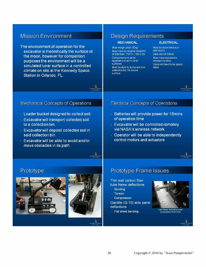
Mission Environment
The environment for the excavator is
theoretically the surface of the moon, however for
competition purposes the environment will be a
simulated lunar surface in a controlled climate on
site at the Kennedy Space Station in Orlando, FL.
System Requirements
The fundamental system requirements were
provided by NASA in the form of official field, game
play, and technical rules for the ESMD mining
competition, seen in Appendix A. Other system
requirements were derived in addition to the ones

6 Copyright © 2010 by “Team Pumpernickel”
provided by NASA based on Functional,
Performance, Interface, Verification, and
Supplementary requirements of the system. A list of
the most important derived system requirements can
be seen in Table 1.
Table 1: System Requirements
F
The excavator shall collect, transport, lift, and
deposit the lunar simulant
F
The excavator shall be operated via
telecommunications
P
The excavator shall collect at least 10kg of
simulant in 15 minutes
P
The excavator shall lift the simulant at least one
meter above the surface of the playing field
I
The communication system shall interface with
NASA’s wireless network
V
The prototype excavator shall be tested according
to the functional requirements on or before 26
February 2010
V
The final design of the system shall be verified
according to the Competition Rule Book
requirements on or before 01 May 2010
S
The excavation hardware must be equipped with
an emergency stop
S
The excavation hardware must be able to operate
under semi-lunar like conditions as described by
Rule 25 of the Competition Rule Book [2]
S
The excavation system shall be designed,
fabricated, and verified using less than $5000.00
The requirements for each subsystem and subsequent
component were derived from the system
requirements and will be discussed in further detail
in each subsystem’s appropriate section.
Concepts of Operations
The system was initially divided into two fields:
Mechanical and Electrical, and the system Con-Ops
were developed based on the system requirements.
The mechanical Con-Ops were derived based
primarily on the functional requirements in Table 1
and can be seen in Fig. 4.
Figure 4: Mechanical Con-Ops
The resulting mechanical Con-Ops were Traverse
and Dig / Transport / Deposit. The Electrical Con-
Ops were derived based primarily on functional and
performance requirements in Table 1 and can be seen
in Fig. 5.
Figure 5: Electrical Con-Ops
The resulting Con-Op was Telerobotic Operation. A
fourth Con-Op, Subsystems Integration was created
in order facilitate the interfacing of subsystems.
Major Reviews: Team Pumpernickel came onboard the ESMD
project after the Mission Concept Review (MCR)
and the Mission Design Review (MDR) had already
taken place on the prototype excavator system.
Team Pumpernickel conducted a Preliminary Design
Review (PDR) after prototype testing on
Engineering Day, this can be found in Appendix B.
The PDR addressed problems pertaining to the
prototype excavator and how system requirements
would be met. The PDR resulted in a key decision
point which involved the redesign of the critical
excavator subsystems. This was decided after
cost/benefit analysis was performed on the proposed
prototype modifications. The Critical Design
Review is scheduled to take place on 1 May 2010

7 Copyright © 2010 by “Team Pumpernickel”
and the Readiness Review is scheduled to take place
on 15 May 2010. The Critical Design Review will
address remaining design proposals, and the
Readiness Review will address remaining actions
required for preparation of the ESMD competition
Interfaces
Before each subsystem was designed in detail, a
list of interfaces was drawn up so that each member
knew how his component(s) would have to interact
with others. This interaction was accounted for in the
design of each subsystem and consequently each
component by becoming a derived requirement. All
interfaces were broken down into five categories
dependent on what two components were being
interfaced. The five categories where: Mechanical to
Mechanical, Mechanical to Mechatronic, Mechanical
to Electrical, Electrical to Mechatronic, and
Electrical to Electrical. A list of all the interfaces and
how each was accomplished can be seen in
Appendix C.
Architectural Design and Development:
The overall architectural design of the excavator
was developed using functional analysis of the Con-
Ops of the excavator. The resulting architectural
design included a Drive, Digger Arm, Frame, and
Communication and Control subsystems. The
architectural design layout can be seen in Fig 6.
Figure 6: System Architectural Design
Frame Subsystem:
The interfacing of the three main functions led to
the development of the fourth critical subsystem
which allowed for ease of subsystem integration. It
was decided to use a frame system to which each
subsystem could be attached and interfaced. The
final frame proposal resulted in a body-on-frame
design composed of 8020 Inc. aluminum
components and aluminum exterior body panels.
The main focus for the new design of the frame
subsystem was driven by increasing rigidity of the
frame subsystem. This requirement was derived after
the testing of the prototype excavator and the
interfacing of the other subsystems. The prototype
excavator’s frame was composed of thin wall carbon
fiber tubes joined by G-10 Garolite. The weak
nature of hollow tubes caused deformations, as seen
in Fig 7, and the prototype frame subsystem did not
meet rigidity requirements even after steps were
taken to remedy such issues.
Figure 7: Bulging Carbon Fiber Tube at Drive
Interface of Bearing Mount
The main focus for the new design was driven by
increasing rigidity of the frame subsystem. Other
driving derived requirements for the frame
subsystem were:

8 Copyright © 2010 by “Team Pumpernickel”
The frame shall not weigh more than 30kg
o Derived from the overall weight
requirement of the excavator system
as per NASA Competition Rules [2]
The frame shall not exceed 19.5”
o Derived from the overall width
requirement of the excavator system
as per NASA Competition Rules [2]
The frame subsystem shall be fabricated on
or before 17 March 2010
The product hierarchy, seen in Fig 8, was
developed after analyzing the requirements imposed
on the frame subsystem.
Figure 8: Frame Subsystem Product Hierarchy
Trade studies were conducted after the basic
architectural design for the frame subsystem had
been laid out. The most important trade study
involved an investigation of Super Droid Robots,
Inc. HD2 Treaded Tank Robot seen in Fig 9 [5].
Figure 9: Super Droid Robots, Inc. HD2 Treaded
Tank Robot [5]
The HD2 Robot consists of a welded aluminum
frame to which the HD2 drive and control
subsystems are interfaced [5]. One possibility for
the design of not only the Frame but also the Drive
and Com/Control subsystems of the new excavator
involved purchasing the prefabricated HD2 Tank
Robot. This option was deemed not feasible due to
the price of the HD2 Tank. The HD2 Frame, Drive,
and Com/Control subsystems would cost over
$6000.00 in order to meet system requirements. This
cost would not include the addition of the Digger
Arm subsystem. Super Droid Robots, Inc. offers
other smaller and less expensive prefabricated
treaded tank robots, but these were deemed not
feasible due to the inability to meet the performance
requirements of the excavator system.
It was determined to design and fabricate a new
frame after the trade studies were complete and after
verification of the prototype excavator. The basic
architectural layout was determined to mirror the
prototype excavator’s layout in order to reduce the
design time. The driving requirement for the new
frame design involved increasing frame rigidity.
The design of the frame subsystem was based on
Developing a decision matrix for determining
the material to be used
Conducting fabrication feasibility tests for
frame joining options
Researching the underlying design motives of
the selected material for interfacing of other
subsystems.

9 Copyright © 2010 by “Team Pumpernickel”
The material choices for the new frame consisted
of either reusing old 8020 Inc. aluminum
(www.8020.net) or using new steel. The size and
profile of the steel was chosen such that weight of
the steel components equaled the weight of the 8020
components. It was decided to use 8020 Inc.
aluminum after constructing a decision matrix. The
decision matrix for the frame design can be seen in
Table D.1 of Appendix D.
The method for best joining the 8020 frame
components was analyzed based on fabrication
feasibility tests and the original intent of design for
8020. 8020 was originally designed to be bolted
together, eliminating the need for welding [6].
Welding components, however, is lighter than using
fasteners as with traditional 8020. The option of
welding 8020 was eliminated after the fabrication
tests revealed extreme difficulty in welding.
The inherent design of 8020 was not only to
eliminate welding and provide an easily fabricated
base frame, but also to provide ease of attaching
other components or subsystems to the base frame
[6]. This was an influencing factor in choosing 8020
because it lent the easiest interfacing between the
frame and the other subsystems. The Drive and
Digger Arm subsystems need only take into account
the available connecting options as quasi
requirements.
The design of the body was based primarily on
past prototype verification. The prototype
verification revealed a lack of structural integrity
between the interface of the Prototype Drive and the
Prototype Frame subsystems. The resulting design
of the body panels consisted of using aluminum
sheet panels riveted to the base frame. The rivets
were staggered providing greater structural strength
to flat plate bending. Additional design decisions
were made in an attempt to improve the Prototype
Drive and Prototype Frame interface which will be
further discussed in the Drive Subsystem section.
The aluminum sheet metal was determined
satisfactory for serving as a base mount for the
Com/Control subsystem. Proper steps need only be
taken to ensure insulation for the Com/Control
subsystem and to ensure wireless antenna reception.
Battery mounts would be similar to the HD2 Tank,
since the excavator batteries are identical to the HD2
Tank batteries. The controller and other PC boards
would be mounted in the middle of the cavity in a
similar fashion to the HD2 Tank, and the required
kill switch would be added at a later time.
The resulting frame design consisted of a body-
on-frame design fabricated out of salvaged 8020 Inc.
aluminum HT slot frame parts joined using
traditional fastening options (nuts and bolts) and a
new aluminum sheet metal body. The resulting
complete chassis can be seen in Fig. 10 and the body
panels can be seen in Fig. 11.
Figure 10: Body-on-Frame design for the Excavator
Figure 11: Body Panels for Frame Subsystem
The frame components and subsystems were
verified before manufacturing based on component

10 Copyright © 2010 by “Team Pumpernickel”
mating, overall dimensions, structural integrity, and
approximate weight using Solid Edge. The
components were then manufactured and installed
piecewise. The resulting frame subsystem can be
seen in Fig 12.
Figure 12: Assembled Frame Subsystem
The interfaces of the Frame subsystem with the
Drive and Com/Control subsystems were verified,
and will be discussed in the “Subsystem –
Subsystem Verification” section. A bill of materials
for the frame subsystem can be found in Table E.1 of
Appendix E.
Drive System:
In order for the excavator to complete its tasks it
must be able to move. There are many ways to do
this and the drive system design will be described in
detail shortly. Additionally with the excavator
weighing as much as it does or can the drive system
must also be robust. The outcome of the design
process led us to settle on a simple track drive
system. The system consists of one tread for each
side, along with one motor per wheel; giving us a
total of four motors. The power transmission is
achieved by employing a chain and sprocket gear
system. The main advantages to this system are zero
degree turning radius, ability to traverse multiple
terrains, and simplicity of design.
The main focus for the drive subsystem was
driven by increasing the turning torque provided by
the motors during zero degree turns. Other driving
derived requirements for the drive subsystem were:
The drive wheels shall not be mounted
directly on the motors
The treads shall be properly tensioned and
aligned
The wheel shafts shall be supported such that
they experience minimum deflections
The product hierarchy, seen in Fig 13, was
developed after analyzing the requirements imposed
on the drive subsystem.
Figure 13: Drive Subsystem Product Hierarchy
Now that the frame had been designed the next
step was to look into the drive system. The first thing
that needed to be done was to assess the performance
of the drive system that the prototype excavator
used. The prototype had two motors that were
directly attached to two drive wheels that drove the
treads. The vehicle turned by simply having one side
go forward while the other side goes in reverse, this
type of steering is called skid steer. Additionally the
prototype had both motors mounted directly to the
side panels with no internal support. Once the system
was finally installed in accordance with the previous
design it was obvious that the design would not
work, there was too much deflection in the system
which made it impossible for the treads to remain on
the wheels for any substantial amount of time. An
example of such deflection is shown in Fig 14

11 Copyright © 2010 by “Team Pumpernickel”
Figure 14: Shaft Deflection on Prototype
The main issues arose in the mounting of the
motors, power transmission, and the mounting of the
drive shafts. Solutions to all of these problems were
discovered and will be discussed in the detailed
design of the drive system. Engineering Day was
used for verification purposes; the performance of
the excavator was sub-par to say the least. Now that
a base had been established for the drive system and
it was noted that a new design was required the next
task was brainstorming and coming up with several
options; then narrowing those down to a group that
are both feasible and efficient in providing the
motion for the excavator. Once brainstorming was
complete and the list narrowed only three options
remained.
Improving upon the treaded design that was
employed on the prototype
Changing to a traditional drive system similar
to what most cars employ
Switching to a multi-wheeled system that
uses skid steer for turning
Ultimately the treaded design was chosen for reasons
to be explained momentarily.
As mentioned, one choice was a traditional drive
system similar to what most cars use today. What
this would entail is a four wheel system with the rear
two wheels being driven by independent motors and
the front two wheels would be the steering wheels,
and would turn just like the front wheels in a
traditional automobile. The power transmission from
motor to drive wheel would be accomplished by a
chain and sprocket system. A major cause for
concern was the design of the steering linkages, with
the timeline being what it is for this project a
complete design of a complex steering system would
be impractical. Additionally with only four wheels a
limited amount of surface area for the excavator to
ride on, this could permit the excavator to sink into
the regolith and render it motionless. Lastly, and
maybe the most important argument against this
design is cost, this design does not call for the use of
many parts, if any from the prototype. Taking into
account these three main concerns it was decided
that this design was not a good fit for this application
so it was discarded.
The other alternative discussed was a multi
wheeled system that uses skid steer. This system is
similar to the previous alternative in that it uses four
wheels to support the weight of the excavator and
two motors to provide the power; however where
this system differs is in the steering. This design calls
for the use of skid steer, which as discussed earlier is
the use of differential velocities to turn a vehicle.
The main concerns with this design were the lack of
surface area, also there was large concern about
turning in regolith with this system. Since it only has
two motors when the excavator went to turn it was
believed that it would simply dig itself into the dirt
since the front wheels would essentially dig into the
regolith instead of skidding over the top like desired.
This system also required for all of the parts to be
purchased and most of the parts from the prototype
to be scrapped. Taking into account the budget and
the concern over turning it was decided that this
system too was unacceptable.
The next step was developing a detailed design
of the drive system and components after an
architectural design had been decided. Since a tread
system was to be employed many of the parts from
the prototype were able to be salvaged. Among
those parts was a tread set that the previous group
had purchased along with the wheels that were
machined to match the timing of the treads. Also
able to be taken were the two motors that they had
purchased to drive the treads. The previous team had

12 Copyright © 2010 by “Team Pumpernickel”
purchased a set of treads from super droid robots and
instead of purchasing the wheels as well they
machined them in our on-campus machine shop.
Here is really where the design of the current
system began, as mentioned above there were some
major issues with the previous system that had to be
corrected. So the initial task was to solve those
issues so that the system could be tested to set a
baseline for performance. There are several key
solutions that are implemented in the current design
to eliminate the issues that were experienced with
the prototype. Among those are internal motor
mounts to eliminate motor deflections, the side panel
which serves as the interface between the drive and
frame systems, being made out of aluminum in order
to reduce deflections, and also the addition of a chain
and sprocket power transmission system. The chain
and sprocket is by far the most crucial addition, the
old design would not produce enough torque for the
excavator to turn on any surface, and the motors that
were installed were decided upon by looking at how
fast they could propel the excavator so it had great
speed in forward and reverse. So in order to increase
the torque a 10 tooth drive gear, 30 tooth sprocket,
and 10 feet of #35 ANSI chain were purchased and
installed in the system as shown in Fig 15 & 16.
Figure 15: Installed Drive Sprocket with Chain
Figure 16: Installed Wheel Sprocket with Chain
This not only produced a 3:1 reduction in the
drive system but also allowed for the motors to not
be directly mounted to the drive wheels, which was a
key goal of the design. Now that the drive wheels
were no longer mounted directly to the motors the
issue of shaft deflections could be easily addressed,
the solution that was chosen was to use solid shafts
that would run the width of the excavator, both the
driven wheels and the un-driven wheels would ride
on these shafts and spin freely. The last of the major
issues with the previous design was the tension of
the treads; the supplier was contacted and provided
the information on the amount of tension the treads
should be under. Next a tensioning system was to be
designed that would keep a constant tension in the
system. The result was an idler pulley attached to a
rotational spring that would allow for flexibility in
the treads while still keeping them in constant
tension. This design can be seen in Fig 17. So
through these design alterations and additions all of
the initial concerns with the design were resolved.

13 Copyright © 2010 by “Team Pumpernickel”
Figure 17: Design of Tensioning Device
Once the system was installed it was taken for a
test run and performed admirably on most surfaces,
however the excavator still experienced some
difficultly turning in rougher terrain. In order to
address this, the design was revisited and several
trade studies were performed. The ultimate decision
made was to purchase two additional motors
resulting in the excavator having all four wheels
driven. This would provide more than adequate
turning torque in all surfaces. Since part of the
design of the frame was for it to be “open” there was
plenty of room for this addition. A full bill of
material for the drive system can be found in Table
E.2 of Appendix E.
Unfortunately, since the drive system has not
been entirely installed the verification of it has yet to
be fully preformed. However through previous tests
and trade studies this design is thought to be
sufficient for any terrain that the excavator could
experience, on this planet or any other.
Digger Arm:
The design of the Digger Arm subsystem was driven
by the following derived requirements:
The Digger Arm shall lift the simulant at
least 1m
The Digger Arm shall collect at least 10 kg
The Digger Arm shall be fabricated with
salvaged parts
The product hierarchy, seen in Fig 18, was developed
after analyzing the requirements imposed on the
Digger Arm subsystem.
Figure 18: Digger Arm Product Hierarchy
The Digger Arm subsystem was separated into two
components, the Arm Boom and Bucket
components.
Arm Boom:
The design of the Arm/Boom subsystem was driven
by the following derived requirements:
The pivot point of the bucket subsystem shall
lift higher than 1.15m
The Arm/Boom actuator shall not exceed
1300 lbs dynamic load
There were many concepts of the digger arm
which were sorted through for a possible design. The
forklift, overhead scoop and dump, front end loader,
and back hoe were all designs which were under
consideration as a possible design to use on the
excavator. The Forklift is front heavy and consisted
of many parts. The overhead scoop and dump
required a greater field of vision and is likely to miss
the dumping bin. In order to operate the back hoe,
the excavator had to be very heavy; it required more
actuators, and a smaller bucket. Considering the
alternatives, the team decided to use a front end
loader.
We designed the front end loader to be simple
and effective. After the design of the first concept, it
was noticed that speed was a huge problem. This
problem was caused mainly because of the height
where the bucket arm is pivoted in accordance to
where it is pivoted on the bucket, see Fig 19.

14 Copyright © 2010 by “Team Pumpernickel”
Figure 19: Prototype Arm Design
To have a design which could handle the moment
caused by an instant stop of the excavator while it is
traveling at full speed and also rise faster than the
conceptual design, the height of the arm’s pivot
position must be reduced, see Fig 20.
Figure 20: Proposed Arm Design
Reducing the height of the pivot position caused
other problems which had to be solved. One problem
was not being able to reach the dumping bin.
Because of the reduced height of the pivot position,
when lifting the arm we needed a longer length to
reach the dumping bin. This was a simple solution
but the longer length causes us to have to use a
shorter bucket because of the length restrictions in
the rules of the competition. If we position the
shorter actuator accordingly, we are able to make the
rise time three times faster, load size heavier, and
also maintain a stop of the excavator when traveling
at full speed. The actuator which we currently have
is offered with a shorter stroke length but
unfortunately, it is on backorder and will not be
available before the subsystem design deadline.
Figure 21 shows the assembly of the arm on the
frame and the shorter actuator.
Figure 21: Proposed Arm Interfacing
For competition deadlines, we were able to come
up with a design which could use our current
actuator while the shorter actuator is being ordered.
To do this we increased the height of the pivot which
is used to connect the actuator to the arm. A Bill of
Materials may be found in Table E.3 of Appendix E.
Bucket:
The bucket system’s derived requirements stem
from the requirements imposed upon the Digger Arm
subsystem and the Prototype Excavator Bucket
subsystem. The prototype bucket design consisted of
a Garolite G-10 bucket that was attached to the main
arm via a steel shaft as seen in Fig 22.
Figure 22: Prototype Bucket Design

15 Copyright © 2010 by “Team Pumpernickel”
This design was not verified due to the Prototype
Frame and Prototype Drive subsystem testing. The
design, however, was believed to have insufficient
stiffness and robustness for digging and accidents.
The new design was driven by the requirements
of being sturdy let light weight. In order for the
Digger Arm subsystem to effectively collect and
deposit the most simulant in one trip, the bucket
must be of minimal weight. The following were the
additional key driving requirements pertaining to the
design of the Bucket subsystem.
The Bucket shall dig with at least 22 kPa at
the tip of the bucket
o Requirement derived from regolith
simulant technical paper [7]
The collected regolith shall not cause the
rover to tip forward
The bucket shall pitch forward at least 145
degrees with respect to the horizontal
The bucket actuator shall support no more
than 500 lbs
After the architectural design of the subsystem
had been laid out, trade studies were performed and
critiqued according to the system and bucket
subsystem requirements. The primary focus of the
trade studies dealt with medium to large scale front
end loader components such as the Bobcat loader
bucket seen in Fig 23.
Figure 23: Bobcat Loader Bucket [8]
The trade studies proved not feasible as a direct
solution, thus leading to the design of a custom
bucket. The operation of a front end loader was also
observed, providing valuable insight into the design
of a bucket system. The use of teeth, maximum
pitch angle, and actuator position on the bucket were
observed in operation and taken into account during
the design process. Teeth increase the pressure at the
digging point, thus reducing the amount of force
needed to penetrate the surface of the simulant. The
bucket design was to imitate that which industry has
already proven, only on a smaller scale.
A decision matrix was used to determine how the
remaining requirements would be satisfied. The
bucket decision matrix can be seen in Table D.2 in
Appendix D. The results of the decision matrix
indicated that an aluminum bucket with a sub frame
would best suit the bucket design based on the
derived requirements. The actuator attachment to the
bucket was designed based on front end loader
observations, the required pitch angle, and maximum
available force from the bucket actuator. The
available digging force was calculated to ensure it
met the derived requirement. The results of the
process consisted of a bucket made of aluminum
sheet metal with an aluminum sub frame, steel
cutting blade with teeth, 8020 compatible interfacing
components, and placement of the actuator
approximately 3” from the bottom pivot. The Solid
Edge CAD assembly of the bucket can be seen in
Fig. 24.
Figure 24: Bucket Design
The physical dimensions, weight, Digger Arm
interface, and Pitch angle of the bucket design were

16 Copyright © 2010 by “Team Pumpernickel”
verified using Solid Edge, and the actuator forces are
in the process of being verified using Working
Model. The Bill of Materials for the Bucket System
can be found in Table E.3 of Appendix E.
Control Communication System:
The driving requirements for the electrical
subsystem were:
The CC subsystem shall interface with
NASA’s wireless network
The excavator system shall be remotely
controlled
The CC subsystem shall provide enough
power for at least 15 minutes
The product hierarchy, seen in Fig 25, was developed
after analyzing the requirements imposed on the CC
subsystem.
Figure 25: Control Communications Product
Hierarchy
The two systems that comprise the total electrical
system are the base station and the teleoperated
vehicle. The base station consists of a laptop with
the necessary Python software installed and an
internal wireless modem capable of connecting to an
external wireless network. The vehicle’s electrical
system consists of a WiPort evaluation board that
receives control commands wirelessly and passes
them on to an Arduino Mega microcontroller. The
Arduino Mega interprets the received serial
commands and formats them according to the
Sabertooth motor controller specifications. These
commands are then sent to one of three Sabertooth
motor controllers, which control and provide power
to the drive and digging systems. A 12V battery
provides power for the WiPort Board, wireless
camera, and Arduino Mega, while two 24V batteries
in parallel provide power for the motor controllers
and thus the driving and digging systems.
The electrical system implemented in the
prototype lunar regolith excavator used a XBee
wireless module to enable communication between
the laptop base station and a Serializer robot
controller. Relatively simple text control commands
were interpreted by the Serializer and either used to
control one of two onboard H-bridges or a
Devantech MD22 motor controller via a single I2C
interface. The address system used in I2C interfaces
ensured that additional motor controllers could be
added to the system should mechanical design
changes require more motors.
While the prototype electrical system did allow
for the remote operation and control of the excavator,
several severe limitations soon surfaced during
testing. The Serializer’s two onboard H-bridges,
while useful, were limited by both the relatively low
12V, 2A limit imposed by the Serializer’s design.
Since the actuators chosen by the mechanical team
were rated for a maximum current draw of 2.9A
during a full stall condition, this meant that the
possibility of causing permanent damage to the
electronics during regular operation was significant.
Also, the analog ports on the Serializer were input-
only. This design limitation forced the team to select
an I2C motor controller that was less than ideal, as
no other way of communicating with an outside
board could be found. The XBee module was an
extremely convenient means of communicating with
the vehicle, but the XBee system is designed to
function as an ad-hoc, point-to-point wireless
network. The LMC rules state that all
communication between vehicle and base station
must pass through NASA’s onsite wireless network.
As there was no way of using the XBee modules on
this network, major network design changes were
required. But perhaps the strongest argument against
the prototype electrical system was the software
required to communicate with the Serializer and thus
the rest of the vehicle. The Serializer robot
controller is not an open-source platform, and all
programming must be done with the use of Visual

17 Copyright © 2010 by “Team Pumpernickel”
C++ and Microsoft Robotics Developer Studio
software libraries provided by the manufacturer. As
no team members were familiar with Visual C++, the
Robotics Developer Studio libraries and thus
development environment was used. However, the
libraries had not been updated to function with the
newest version of the development environment.
This caused many problems with implementing
features such as rear collision detection and
automated arm control. The software was also found
to respond somewhat erratically to gamepad joystick
input, resulting in erratic and sometimes total loss of
vehicle control.
The final excavator electrical system is similar in
functionality to the prototype but features a much
more versatile and reliable set of components. In
place of the XBee modules, a Lantronix WiPort
evaluation board is used to connect the vehicle to an
onsite wireless network and relay serial commands
between base station and vehicle. Since the WiPort
board also has several onboard general purpose
digital pins, it is used to remotely trigger relays that
control the power to the rest of the vehicle. This
functionality allows for remote powering on and off
of the vehicle, which is required in the 2010 LMC
rules. Also capable of controlling vehicle power is a
red emergency stop button mounted on the rear of
the vehicle. The WiPort board passes all serial
command signals to an Arduino Mega
microcontroller. The Arduino Mega receives analog
sensor data from a Sharp GP2D120 IR rangefinder
and sends control commands to one of three
Sabertooth 2x10 motor controllers. The IR
rangefinder has a reliable proximity detection range
of between 4cm and 22cm, which is enough to
provide ample warning of a rear collision. Each
Sabertooth motor controller is capable of providing
up to 24V and 8A to two DC motors, which is more
than enough to power the four drive motors and two
linear actuators that are used in the vehicle. A
Linksys wireless video camera provides the operator
with a live video feed of the excavator’s
surroundings, enabling true remote operation. The
motor controllers are powered by two 24V batteries
wired in parallel, and the rest of the electronics are
powered by a single 12V battery.
As per the rules given out by NASA, the
excavator must be remotely controlled and receive
start/stop signals through the NASA WiFi network.
In order to accomplish this, the design process was
implemented in the design of a software system for
the excavator. The purpose of the software system is
to provide control to and feedback from the
excavator remotely. To ensure that the software
system provided these services while following the
competition rules given by NASA, the design was
based off a set of user requirements. After
enumerating the requirements, the decisions about
what framework to use and how to layout the
software system. A simple schematic of the system
can be seen in Fig 26.
Figure 26: Software Schematic
The requirements that the software system
adheres to is based on the rules given by NASA and
by other requirements imposed by the team. These
are the requirements that the software system
adheres to:
All communication shall travel over NASA’s
WiFi network
All data communication shall not exceed 5Mbps
The excavator shall be remotely started and
killed
The excavator shall be remotely controlled using
a gamepad or joystick
Information from the excavator shall be
displayed (voltage, backup obstacle detection,
etc...)

18 Copyright © 2010 by “Team Pumpernickel”
In order to facilitate serial communication
over a WiFi network, the Lantronix WiPort device
was selected as the gateway for communications to
and from the Arduino Mega. The data transfer
budget was rationed between the WiFi webcam and
the connect to the Lantronix, but the communication
between the computer and the Lantronix WiPort is
negligible. The Lantronix board has some general
purpose I/O ports that we will use to control the
remote start and kill functions. The Input from the
gamepad or joystick will be translated into a format
that the Arduino Mega understands and sent from the
Laptop to the Lantronix and ultimately the Arduino
Mega from the Control Software. Any information
collected from the Arduino Mega will be published
to the Lantronix, which relays that information to the
Control Software which then processes the
information and displays it to the user.
The Lantronix WiPort board was selected to
facilitate the communication of serial data over the
NASA WiFi link. The Lantronix achieves this by
connecting to a preconfigured WiFi access point and
setting up a telnet server. Telnet is simple a legacy
modem protocol, allowing us to easily send
asynchronous serial data over a TCP socket.
Basically the Lantronix board allows for transparent
communication with the Arduino as if it were
connected via USB. Conveniently the Lantronix will
also allow us to enable/disable power to the
excavator via the NASA WiFi as well. This is
accomplished by sending a specially formatted UDP
data packet to the Lantronix which instructs it to set
certain Digital I/O pins to High or Low states. Using
this feature we will set a pin High in order to enable
a relay controlling power to the electronics, and
conversely setting it Low to disable power flow to
the excavator electronics.
Now that a solution had been found for WiFi
connection the control software needed to be
designed and implemented. The Control Software
has several main functions:
Manage connections to the Lantronix WiPort
Send the enable/disable command to the
Lantronix WiPort
Translate Input from the gamepad or joystick
into commands
Send commands to the Arduino Mega via the
Telnet server on the Lantronix WiPort
Display any information the Arduino Mega sends
back In order to accomplish this goal the software
framework needed to be able to fulfill these
requirements:
Connect to the Excavator via TCP/IP Telnet
(Lantronix)
Connect to the Excavator via USB (Serial via
direct connection to the Arduino)
Interface with gamepads and joysticks
Operate under Graphical User Interface
Environment
Easy to use / Rapid Development (short
development time)
(optional) Cross-platform compatible (Windows,
Mac OS X, Linux) development time)
(optional) Display streaming video from the
WiFi webcam After reviewing the requirements the decision
was made to use the Python (2.6.x) programming
language to develop the Control Software due to the
fact that it is easy to use, supports Telnet, supports
Serial, supports Simple GUI’s, supports interfacing
with gamepads and joysticks, and is cross-platform
compatible. Additionally the pygame library was
chosen to facilitate the GUI and gamepad/joystick
interfacing. In order to communicate through a
Serial port the pySerial library is also required.
In testing, the redesigned electrical system
performed exactly as expected. The two battery
systems were more than capable of powering the
onboard electronics for the necessary 15 minutes,
and the WiPort board can be configured to connect to
any wireless network. Once that connection was
made, sending control commands to the Arduino
Mega resulted in no unexpected behavior
whatsoever. This was a significant improvement
over the unreliable Serializer board and associated
software used in the prototype vehicle.
Verification and Validation:
The verification for the Team Pumpernickel’s
project began with the prototype excavator. It
underwent frame and drive modification as well as

19 Copyright © 2010 by “Team Pumpernickel”
Frame and Drive subsystem integration. The
prototype excavator verification of system
requirements as defined by the Lunabotics Mining
Competition Rule Book took place on Engineering
Day at Auburn University, and the results involved
the design a new excavator based heavily on solving
the problems experienced in the prototype’s
verification.
Solid Edge was used for the physical verification
(weight, dimensions, etc.) of components and for the
integration of components into subsystems. The
subsystems were then assembled into a system and
verified against the system requirements as defined
by the Competition Rule Book. The resulting
excavator system Solid Edge CAD assembly can be
seen in Fig. 27.
Figure 27: System Solid Edge Verification
FEMAP express, Working Model, and hand
calculations were used to test the deflection and
force/load requirements on each subsystem are met.
The Frame, Drive, and Com/Control subsystems
have begun system integration and the verification of
subsystem requirements. The remaining subsystems
and excavator system have not been verified at this
time. A check list of remaining tasks before system
verification can be found in Appendix F. The plan for
system verification includes:
Resource Budgets:
One crucial part of any design is how the
technical resources are distributed. This project had
three designated technical resource budgets in
weight, power, and data transfer rate. A technical
resource budget was derived and can be seen in
Table G.1 of Appendix G.
Risk Management:
The Excavator system that was created is a high
risk system. The subsystems were designed around
the basic necessities needed to fulfill requirements in
an attempt to keep the overall weight and design
time of the excavator to a minimum. Table H.2 of
Appendix H shows examples of components that are
not mission critical and the associated risk involved
with each component as per Chapter 2: Systems
Engineering Risk Management guidelines [3].
CONFIGURATION MANAGEMENT:
In today’s engineering world computers are
almost always involved in the design of systems and
the solution of problems. One of the results of this is
there are many computer files created during the
design of a system such as a lunar excavator. One of
the struggles is how to best organize and index all of
these files so that all members are aware of their
places. This is commonly referred to as configuration
management and is a common problem in today’s
workplace, even outside of engineering. In order to
keep all of the files created throughout this project
several different techniques were used. There was a
common drive provided by the school that all
members had access to so this served as the main
storage point for all files. Each member had an
individual file on this drive where they would keep
the work that they were currently working on; once
the file was completed it was moved into a file
corresponding to the subsystem it belonged to. Also
once a new file was uploaded, if it was replacing an
older version the older version was renamed and
saved in an additional folder under that subsystem
specifically for older designs. This was done so that
in the event a new design did not work the old design
could easily be reinstated. However since this drive
was only accessible from a school computer a way to
easily share current files needed to be found and
implemented, the website dropbox.com provided this
capability for this project. This site was used for

20 Copyright © 2010 by “Team Pumpernickel”
sharing files while members were away from
campus. Through using both of these services and
the explained organizational structure no problems
with configuration management were experienced
throughout the design process of the excavator.
PROJECT MANAGEMENT:
Management Structure:
The Management structure, seen in Fig 28, for
this project was similar to that of real world project
in that there was a systems engineer who oversaw
the whole project, then there where both mechanical
and electrical engineering project leads followed by
mechanical and electrical engineers.
Figure 28: Management Structure Diagram
Schedule:
As is with every project, the excavator had a
timeline for completion that must be met in order to
complete the mission statement. This timeline was
established by all of the members at the onset of this
semester and has been altered to add new tasks when
needed. Each subsystem had its own schedule for
completion and an accompanying Gantt chart; those
may be found in Appendix I. The Gantt chart for this
semester may also be found in Appendix I.
Financial Budget:
One of the key factors in any project is the
financial budget; with the economy in its current
state money is something that is always important to
keep a close eye on. This project is no different; the
group was given a project budget at the beginning of
the semester. One of the tasks assigned to the
systems engineer was to ensure that the money was
being spent properly and that the project stayed
under budget. A copy of the budget can be found in
Appendix J.
DELIVERABLES:
In order to ensure that each task is being
completed and being done in accordance with the
schedule each team member was required to provide
a contract of deliverable (COD) at the onset of each
process he began. The COD was then signed by the
team member, the system engineer, and the
instructor. These were graded assignments for each
student so if the contract was not fulfilled then the
student’s grade would suffer from it. CODs were
written for a wide variety of tasks from placing
orders for parts to constructing the entire frame.
CODs are attached in Appendix K to show how they
were written and implemented into this project.
CONCLUSION:
Prototype Evaluation:
The first task that was undertaken by the team
was to evaluate the prototype and establish a
baseline of performance so that it could be improved
upon. The team used Engineering Day 2010 at
Auburn University for verification purposes of the
prototype and it was at such time that the team
designated that the design was inadequate to
complete the mission statement. For this purpose the
design process was initiated for a new excavator
design.
New Excavator Design:
As shown in the context of this paper the design
process was instituted on a system, subsystem, and
component level to best ensure that the team arrived
at the optimal design that met all the requirements.
System Verification/Validation:
Every installed subsystem and/or component has
been verified to date. The verification process will
continue until the team departs for Orlando and
compete in the competition, which will serve as the
system launch.

21 Copyright © 2010 by “Team Pumpernickel”
REFERENCES:
1. X-Prize Foundation, http://space.xprize.org/
2. Lunabotics Mining Competition Rules, 11 January 2010,
http://www.nasa.gov/pdf/390619main_LMC%20Rules%202010.pdf
3. Beale, D. and Bonometti, J. “Chapter 2: Systems Engineering (SE) – The Systems Design Process”.
http://www.eng.auburn.edu/~dbeale/ESMDCourse/Chapter2.htm
4. Beale, D. “Student’s Roadmap to MECH4240: Comprehensive Mechanical Design I,” January 2010,
http://www.eng.auburn.edu/users/bealedg/MECH4240-50/
5. Super Droid Robots, Inc. “HD2 Treaded ATR Tank Robot Kit,”
http://www.superdroidrobots.com/shop/item.asp?itemid=789&catid=73
6. 8020 Inc., “HT Series Framing,” http://www.8020.net/HT-Series-1.asp
Metzger, Philip T. and Rahmatian, Laila A. “Soil Test Apparatus for Lunar Surfaces.” Earth and Space 2010:
Engineering, Science, Construction, and Operations in Challenging Environments. 2010 ASCE
7. Root Grapple, “4 in 1 Bucket,” http://www.rootgrapple.com/4in12.jpg

22 Copyright © 2010 by “Team Pumpernickel”
APPENDIX A: Lunabotics Mining Competition Rules

23 Copyright © 2010 by “Team Pumpernickel”

24 Copyright © 2010 by “Team Pumpernickel”

25 Copyright © 2010 by “Team Pumpernickel”

26 Copyright © 2010 by “Team Pumpernickel”

27 Copyright © 2010 by “Team Pumpernickel”
APPENDIX B: Preliminary Design Review
28 Copyright © 2010 by “Team Pumpernickel”

29 Copyright © 2010 by “Team Pumpernickel”

30 Copyright © 2010 by “Team Pumpernickel”

31 Copyright © 2010 by “Team Pumpernickel”

32 Copyright © 2010 by “Team Pumpernickel”

33 Copyright © 2010 by “Team Pumpernickel”
APPENDIX C: Subsystem Interfaces
INTERFACE SOLUTION INTERFACE SOLUTION
Mechanical to Mechanical Electrical to Mechatronic
Frame to Drive Bearing Mounts Controller to Motors Sabertooth 2x10 MC
Frame to Digger Arm Rigid Vertical Posts Controller to Actuators Sabertooth 2x10 MC
Mechanical to Mechatronic Electrical to Electrical
Frame to Motors Side Panel Mounts, Motor Mounts Batteries to Electronics Fuse Buss
Frame to Actuator Hinged Mount Camera to Controller Wireless Network
Drive to Motors Chain & Sprocket Base to Excavator WiPort Board
Digger Arm to Actuator Hinged Mount Network to Motor Controllers Arduino Mega
Mechanical to Electrical Batteries to Relay Emergency Stop
Frame to Batteries Rigid Mount
Frame to Control Board Rigid Mount
Frame to Camera Custom Arm

34 Copyright © 2010 by “Team Pumpernickel”
APPENDIX D: Decision Matrices
Table D.1: Frame Material Decision Matrix
8020 Steel Importance
Material Feature
Rigidity / Strength 4.5 5 5
Ease of Interface 5 4 4
Cost 5 4 4
Use of Fasteners 1 4 3
Ease of Fabrication 5 3 4
Use of salvaged parts 5 1 5
Total 110.5 86
Importance: 1 = Negligible, 5 = Significant
Material Capability: 1 = Poor, 5 = Excellent
Table D.2: Bucket Subsystem Decision Matrix
Steel Sheet Al Body on Frame Importance
Property
Rigid / Strength 5 2 3.5 4
Weight 1 5 4.5 5
Fab/ Install Ease 4.5 4 3.5 2
Total 34 41 43.5
Importance: 1 = Negligible, 5 = Significant
Material Capability: 1 = Poor, 5 = Excellent

35 Copyright © 2010 by “Team Pumpernickel”
APPENDIX E: Bill of Materials
Table E.1: Frame Subsystem Bill of Materials Price
*Excess parts may have been used from / for other subsystems
# Part # Description UC Q EC Source
1 4302 2 Hole Standard Inside Corner Bracket $2.95 42 $123.90 8020 Inc.
2 4306 3 Hole Joining Strip $4.40 6 $26.40 8020 Inc.
3 4332 2 Hole Inside Corner Gusset $4.30 6 $25.80 8020 Inc.
4 4350 4 Hole 90 Degree Joining Plate $5.60 6 $33.60 8020 Inc.
5 8973K33 3003 AL .100" thick 24" x 36" $44.29 3 $132.87 McMaster
6 90652A030
Nylon Insert Thin 5/16-18 Hex Lock Nut pack of
100 $10.30 2 $20.60 McMaster
7 91255A581 BHSCS 5/16-18, 3/4" pack of 50 $10.36 3 $31.08 McMaster
8 92949A594 18/8 SS BHSCS 5/16-18, 3" Pack of 5 $8.42 2 $16.84 McMaster
9 9701-145 1.5" Square Tube With Holes 145"Profile $53.65 3 $160.95 8020 Inc.
10 97447A315 AL Rivets 1/8" Dia, 1/4" Grip, pack of 250 $9.42 2 $18.84 McMaster
Grand Total $590.88
Table E.2: Drive Subsystem Bill of Materials
*Excess parts may have been used from / for other subsystems
# Part # Description UC Q EC Source
1 1139545
M5-0.8 x 12 12.9 Socket Head Cap
Screws $7.85 1 $7.85 Fastenal
2 1688K17
PTFE-Lubricated SAE 841 Bronze
Sleeve Brng for 1/2" Shaft Diameter,
5/8" OD, 1" L $0.98 8 $7.84 McMaster
3 2299K316
Machinable-Bore Flat Sprocket for #35
Chain, 3/8" Pitch, 30 Teeth, 1/2" min
Bore $9.45 4 $37.80 McMaster
4 6261K151
Standard ANSI Roller Chain, #35,
Single Strand, 3/8" Pitch, Rollerless, .2"
Diameter, 10' L $28.80 1 $28.80 McMaster
5 6359K32
Cast Iron Base Mounted Babbitt-Lined
Bearing Split, for 1/2" Shaft Diameter $42.13 8 $337.04 McMaster
6 7321K1
ANSI Roller Chain Attachment,
Connecting Link Style A-1 for #35
Chain $1.67 4 $6.68 McMaster
7 9120K15
Galvanized Low-Carbon Steel Rod 1/2"
Diameter, 3' Length $9.67 4 $38.68 McMaster
8 9946K15
Aluminum Set Screw Shaft Collar 1/2"
Bore, 1" O.D., 7/16" Width $2.05 16 $32.80 McMaster

36 Copyright © 2010 by “Team Pumpernickel”
9 NC13770 Sprocket, 35B10, 12mm Bore $44.48 4 $177.92 Parts Town
10 TD036290
IG52-02 24V DC 290 RPM Gear Motor
w/encoder $122.80 4 $491.20 Super Driod Robots
11 TD05200 4 in. tread set $580.63 1 $580.63 Super Driod Robots
Grand Total $1,747.24
Table E.3: Digger Arm Subsystem Bill of Materials
*Excess parts may have been used from / for other subsystems
# Part # Description UC Q EC Source
1 4330 6 Hole 30 Degree Joining Plate $7.10 6 $42.60 8020 Inc.
2 4345 6 Hole 45 Degree Joining Plate $7.10 4 $28.40 8020 Inc.
3 4376 3 Hole Inside Corner Bracket $4.15 4 $16.60 8020 Inc.
4 4390 3 Hole Pivot Plate $11.50 12 $138.00 8020 Inc.
5 125011 12V, 7 7/8" stroke linear actuator $149.99 1 $149.99 Northern Tool
6 125012 12V, 11 13/16" stroke linear actuator $159.99 1 $159.99 Northern Tool
7 8910K121
Low-Carbon Steel Rectangular Bar 1/8" Thick,
2" Width, 6' Length $18.47 1 $18.47 McMaster
8 8982K21
Multipurpose Aluminum (Alloy 6061) 90 Deg
Angle, 1/8" Thick, 1" X 1" Legs, 8' Length $12.63 2 $25.26 McMaster
9 90652A030
Nylon-Insert Extra-Wide Thin Hex Locknut
Zinc-Plated Grade 2 Steel, 5/16"-18 Thread
Size, Packs of 100 $10.30 1 $ 10.30 McMaster
10 91255A581
Alloy Steel Button Head Socket Cap Screw
5/16"-18 Thread, 3/4" Length, Packs of 50 $10.36 1 $10.36 McMaster
11 91259A540
Alloy Steel Shoulder Screw 1/4" Shoulder Dia,
3/4" L Shoulder, 10-24 Thread $1.03 4 $4.12 McMaster
12 91259A626
Alloy Steel Shoulder Screw 3/8" Shoulder Dia,
1-1/4" L Shoulder, 5/16"-18 Thrd $1.50 3 $4.50 McMaster
13 97526A404
Choose-A-Color Blind Rivet Domed, 3/16"
Dia, .126"-.250" Material Thk, Gray, Packs of
100 $7.00 2 $14.00 McMaster
14 98777A213
High-Strength Zinc-Plated Steel Blind Rivet
Dome, 3/16" Dia, 0.251"-0.375" Material
Thickness, Packs of 25 $8.64 1 $8.64 McMaster
Grand Total $631.23

37 Copyright © 2010 by “Team Pumpernickel”
Table E.4: Com/Control Subsystem Bill of Material
*Excess parts may have been used from / for other subsystems
# Part # Description UC Q EC Source
1 231431 10 POS 15A Termial Strip $3.39 2 $6.78 Jameco
2 282263 15A, 24V DC relay $7.49 2 $14.98 Jameco
3 5183T11
Blade-Style Fuse Block for 6
Atc, AF, OR Ato/257 Fuses,
32 VDC $41.44 1 $41.44 McMaster
4 653-A22E-L-02 DP Emergency Stop (manual) $62.23 1 $62.23 Mouser Electronics
5 7243K116
Fully Insulated Quick-
Disconnect Terminal Dbl
Crimp Fem, 16-14 Awg,.187"
W, .02" Thk Tab, 600V $7.36 1 $7.36 McMaster
6 7587K461
Stranded Single-Conductor
Wire, UL 1015, 14 Awg, 600
VAC, Red, 100' Length $35.16 1 $35.16 McMaster
7 7587K65
Stranded Single-Conductor
Wire UL 1015, 14 Awg, 600
VAC, Black, 100' Length $35.16 1 $35.16 McMaster
8 7964K634
Solid Single-Conductor Wire
UL 1015, 22 Awg, 600 VAC,
White $10.80 1 $10.80 McMaster
9 8026K1
Modular Connector, Kit, 30
Amps at 600 VZC/VDC, Red,
Packs of 5 $3.04 10 $30.40 McMaster
10 8026K1
Modular Connector, Kit, 30
Amps at 600 VZC/VDC,
Black, Packs of 5 $3.04 10 $30.40 McMaster
11 855-R30-3002502 3mm metal standoffs $0.68 50 $34.00 Mouser Electronics
12 91280A102 3mx6m Hex Screw $5.62 1 $5.62 McMaster
13 92005A116
Metri Pan Head Phillips
Machine Screw, Zinc-Plated
Steel, M3 Size, 6mm Length,
.5mm Pitch, Packs of 100 $2.30 1 $2.30 McMaster
14 94150A325
Metric Type 316 Stainless
Steel Hex Nut M3 Size, .5mm
Pitch, 5.5mm Width, 2.4mm
Height, packs of 50 $2.19 2 $4.38 McMaster
15 95225A315 3M washers $8.35 1 $8.35 McMaster
16 TE-088-210
12V 2200 mAHr NiMH 2x5
Battery Pack $23.90 1 $23.90 Super Driod Robots
17 TE-097-320
24V 10000 mAHr NiMH
Battery Pack $259.50 2 $519.00 Super Driod Robots
18 TE-106-018 Smart Charger for 9.6V - 18V $28.95 1 $28.95 Super Driod Robots

38 Copyright © 2010 by “Team Pumpernickel”
NiMH and NiCad
19 TE-106-024
Smart Charger for 19.2V -
24V NiMH and NiCad $29.95 2 $59.90 Super Driod Robots
20 WVC2300
Cisco Wireless-G Video
Camera $359.99 1 $359.99 Cisco
21 Lantronix WiPort $300.00 1 $300.00
22
Sabertooth 2x10 Motor
Controler $79.99 3 $239.97 Dimension Engineering
23 Arduino Mega $64.77 1 $64.77 Robotshops.us
24 XBox 360 controller $49.99 1 $49.99
Grand Total $1,975.83

39 Copyright © 2010 by “Team Pumpernickel”
APPENDIX F: Project Completion / Verification Check List
Complete Arm and Bucket Design
Verify designs meet physical/functional requirements in Solid Edge and Working Model
Fabricate and Assemble: Arm and Bucket Subsystems
Integrate Arm and Bucket components into Arm/Boom subsystem
Integrate Arm/Boom subsystem with the remaining subsystems
Verify subsystems against interface and integration requirements
Verify System against system requirements
Validate System at competition
APPENDIX G: Technical Resource Budget
Table G.1: Technical Resource Budget
SOURCE COMPONENT ALLOTOTTED USED
Weight 80kg
Frame 30kg
Drive 20kg
Arm 20kg
Electrical 10kg
Power 460 Watt-hrs
24 V Motor x4 300 264
Actuator x2 154 139.2
Motor Cntrl x3 3 1.08
Relay x2 3 1.776
12 V 26.4 Watt-hrs
WiPort 5 2.31
Camera 15 12
Micro-Controller 5 1.25
Transfer Rate 5 Mbps
Camera 2.5Mbps 750kbps
WiPort 2.5Mbps 45kbps

40 Copyright © 2010 by “Team Pumpernickel”
APPENDIX H: Risk Management
Table H.1: Failure Classification [3]
Table H.2: Risk Management of Non-Mission Critical Components
Subsystem Component Failure/Result Code Mitigation
Frame
Nuts/Bolts Loose Nuts/Bolts in components 2 Locking Nuts
Side Panel Holes Regolith entering cavity 2 Sealed Panels
Non Critical Members Frame deformations 3 Additional Support
Side Panels Crumpling / Deforming 3 Additional Support
Bottom Panels Crumpling / Deforming 3 Additional Support
Battery Mount Unrestrained batteries 2 Mount failsafe
Controller Mount
Unrestrained controller
components 2 Mount failsafe
IR Mount False position readings 1 Mount failsafe
Antenna Mount Improper signal connection 2 Mount failsafe
Camera Mount Lack of video feedback 3 Mount failsafe
Drive
Nuts/Bolts Loose Nuts/Bolts in components 2 Locking Nuts
Treads Tread derails / tears 3 Four Driving Motors
Chain for one motor Drive chain derails 2 Chain Guard
Drive Sprocket on one
motor Drive sprocket slips 2
Semi-Permanent
Fastening
Chain for two motors Drive chain derails 3 Chain Guard
Drive Sprocket for two
motors Drive sprocket slips 3
Semi-Permanent
Fastening
Motor on one side Motor failure 3 Drive Slower
Two Motors Motor failure 3 Drive Slower
Motor Mounts Unsupported drive motors 2 Mount failsafe
Digger

41 Copyright © 2010 by “Team Pumpernickel”
Nuts/Bolts Loose Nuts/Bolts in components 2 Locking Nuts
Bucket Teeth Tooth breaks 2 Sharp Cutting Blade
Bucket Top Top of bucket fractures 1
Secondary
Reinforcement
Electrical
IR Sensor False position reading 1 Filter
One Battery Limited power 3 Cells in Parallel
Camera Battery No video feedback 3 Cells in Parallel
Actuators / Motors
simultaneously drawing
current
Limited power / Operational
time 3
Individual Actuator /
Motor Cells

42 Copyright © 2010 by “Team Pumpernickel”
APPENDIX I: System Schedule
Table I.1: Excavator System Schedule
System
Task Start Date Duration End Date
Properly Install & Align Treads 2/1/2010 24 2/25/2010 KEY
Stiffen Critical Components 1/25/2010 30 2/24/2010 Jamie
Temporarily Stabilization 2/23/2010 1 2/24/2010 Mark
System Verification 2/24/2010 2 2/26/2010 Ray
(DMIV) 2 Motor Drive System 2/26/2010 31 3/29/2010 All (See Designated Tab)
(DMIV) 4 Motor Drive System 3/28/2010 26 4/23/2010 (DMIV) Tread Tensioner 3/29/2010 25 4/23/2010 (DMIV) Frame Skeleton 2/26/2010 29 3/27/2010 (DMIV) Frame Exoskeleton (2MDS) 2/26/2010 25 3/23/2010 (DMIV) Frame Exoskeleton (4MDS) 3/28/2010 28 4/25/2010 (DMIV) Arm Boom 3/5/2010 56 4/30/2010 (DMIV) Bucket 3/30/2010 32 5/1/2010 Electrical System Integration 4/10/2010 22 5/2/2010 System Verification 5/1/2010 20 5/21/2010
24
30
1
2
31
26
25
29
25
28
56
32
22
20
1/23 2/12 3/4 3/24 4/13 5/3 5/23
Properly Install & Align Treads
Stiffen Critical Components
Temporarily Stabilization
System Verification
(DMIV) 2 Motor Drive System
(DMIV) 4 Motor Drive System
(DMIV) Tread Tensioner
(DMIV) Frame Skeleton
(DMIV) Frame Exoskeleton (2MDS)
(DMIV) Frame Exoskeleton (4MDS)
(DMIV) Arm Boom
(DMIV) Bucket
Electrical System Integration
System Verification
Corp_2 Mechanical Schedule
Figure I.1: Excavator System Mechanical Engineering Gantt Chart

43 Copyright © 2010 by “Team Pumpernickel”
Table I.2: Prototype Schedule
Prototype
Task Start Date Duration End Date Drive KEY
Properly Install & Align Treads 2/1/2010 24 2/25/2010 Jamie
(DMI) Power Transmission Solution 2/1/2010 23 2/24/2010 Mark
(DMI) Motor Mounts 2/8/2010 7 2/15/2010 Ray
(DMI) Tensioning Apparatus 2/18/2010 5 2/23/2010 All
Subsystem Verification 2/15/2010 10 2/25/2010 Frame Stiffen Critical Components 1/25/2010 30 2/24/2010 (MI) Aluminum Side Panels 1/25/2010 14 2/8/2010 (MI) Inner Bracing 2/20/2010 4 2/24/2010 (DMI) Tube Frame Inserts 2/19/2010 3 2/22/2010 (MI) Additional Cross Member 2/23/2010 1 2/24/2010 Subsystem Verification 2/10/2010 14 2/24/2010 Arm Temporarily Stabilization 2/23/2010 1 2/24/2010 (DMI) Rope & Knot System 2/23/2010 1 2/24/2010 Subsystem Verification 2/23/2010 1 2/24/2010 System System Verification 2/24/2010 2 2/26/2010
24
23
7
5
10
30
14
4
3
1
14
1
1
1
2
1/23/2010 1/28/2010 2/2/2010 2/7/2010 2/12/2010 2/17/2010 2/22/2010 2/27/2010
Properly Install & Align Treads
(DMI) Power Transmission Solution
(DMI) Motor Mounts
(DMI) Tensioning Apparatus
Subsystem Verification
Stiffen Critical Components
(MI) Aluminum Side Panels
(MI) Inner Bracing
(DMI) Tube Frame Inserts
(MI) Additional Cross Member
Subsystem Verification
Temporarily Stabilization
(DMI) Rope & Knot System
Subsystem Verification
System Verification
Protoype Gantt Chart
Figure I.2: Prototype Gantt Chart

44 Copyright © 2010 by “Team Pumpernickel”
Table I.3: Excavator Drive Subsystem Schedule
New Excavator Drive
Task Start Date Duration End Date
(DMIV) 2 Motor Drive System 2/26/2010 31 3/29/2010 KEY
Design 2MDS 2/26/2010 3 3/1/2010 Jamie
Manufacture 2MDS 3/15/2010 3 3/18/2010 Mark
Install 2MDS 3/17/2010 6 3/23/2010 Ray
Verify 2MDS 3/26/2010 2 3/28/2010 All (See Designated Tab)
(DMIV) 4 Motor Drive System 3/28/2010 26 4/23/2010 Design 4MDS 3/28/2010 2 3/30/2010 Manufacture 4MDS 4/15/2010 7 4/22/2010 Install 4MDS 4/18/2010 6 4/24/2010 Verify 4MDS 4/24/2010 7 5/1/2010 (DMIV) Tread Tensioner 3/29/2010 25 4/23/2010 Design TT 3/29/2010 14 4/12/2010 Manufacture TT 4/16/2010 5 4/21/2010 Install TT 4/20/2010 2 4/22/2010
31
3
3
6
2
26
2
7
6
7
25
14
5
2
2/24/2010 3/6/2010 3/16/2010 3/26/2010 4/5/2010 4/15/2010 4/25/2010
(DMIV) 2 Motor Drive System
Design 2MDS
Manufacture 2MDS
Install 2MDS
Verify 2MDS
(DMIV) 4 Motor Drive System
Design 4MDS
Manufacture 4MDS
Install 4MDS
Verify 4MDS
(DMIV) Tread Tensioner
Design TT
Manufacture TT
Install TT
Drive Subsystem Gantt Chart
Figure I.3: Excavator Drive Subsystem Gantt Chart

45 Copyright © 2010 by “Team Pumpernickel”
Table I.3: Excavator Frame Subsystem Schedule
Frame
Task Start Date Duration End Date
(DMIV) Frame Skeleton 2/26/2010 29 3/27/2010 KEY
Design FS 2/26/2010 12 3/10/2010 Jamie
Manufacture FS 3/12/2010 3 3/15/2010 Mark
Install FS 3/14/2010 3 3/17/2010 Ray
Verify FS 3/17/2010 10 3/27/2010 All (See Designated Tab)
(DMIV) Frame Exoskeleton (2MDS) 2/26/2010 25 3/23/2010 Design FE 2/26/2010 12 3/10/2010 Manufacture FE 3/11/2010 2 3/13/2010 Install FE 3/19/2010 3 3/22/2010 Verify FE 3/22/2010 1 3/23/2010 (DMIV) Frame Exoskeleton (4MDS) 3/28/2010 28 4/25/2010 Design FE 3/28/2010 2 3/30/2010 Manufacture FE 4/15/2010 2 4/17/2010 Install FE 4/16/2010 1 4/17/2010 Verify FE 4/24/2010 1 4/25/2010
29
12
3
3
10
25
12
2
3
1
28
2
2
1
1
2/24/2010 3/6/2010 3/16/2010 3/26/2010 4/5/2010 4/15/2010 4/25/2010
(DMIV) Frame Skeleton
Design FS
Manufacture FS
Install FS
Verify FS
(DMIV) Frame Exoskeleton (2MDS)
Design FE
Manufacture FE
Install FE
Verify FE
(DMIV) Frame Exoskeleton (4MDS)
Design FE
Manufacture FE
Install FE
Verify FE
Frame Subsystem Gantt Chart
Figure I.4: Excavator Frame Subsystem Gantt Chart

46 Copyright © 2010 by “Team Pumpernickel”
Table I.3: Excavator Digger Arm Subsystem Schedule
Digger Arm
Task Start Date Duration End Date
(DMIV) Arm Boom 3/5/2010 56 4/30/2010 KEY
Design AB 3/5/2010 40 4/14/2010 Jamie
Manufacture AB 4/16/2010 4 4/20/2010 Mark
Install AB 4/18/2010 6 4/24/2010 Ray
Verify AB 4/25/2010 5 4/30/2010 All (See Designated Tab)
(DMIV) Bucket 3/30/2010 32 5/1/2010 Design B 3/30/2010 14 4/13/2010 Manufacture B 4/16/2010 6 4/22/2010 Install B 4/22/2010 3 4/25/2010 Verify B 4/25/2010 6 5/1/2010
56
40
4
6
5
32
14
6
3
6
3/3/2010 3/13/2010 3/23/2010 4/2/2010 4/12/2010 4/22/2010 5/2/2010
(DMIV) Arm Boom
Design AB
Manufacture AB
Install AB
Verify AB
(DMIV) Bucket
Design B
Manufacture B
Install B
Verify B
Digger Arm Gantt Chart
Figure I.5: Excavator Digger Arm Subsystem Gantt Chart

47 Copyright © 2010 by “Team Pumpernickel”
Table I.4: Excavator Electrical Subsystem Schedule
Electrical Subsystem
Task Start Date Duration
End Date
ELECTRICAL SYSTEM KEY
Component Selection 2/26/2010 17 3/15/2010 Mike
Power Distribution 3/3/2010 6 3/9/2010 Eddie
Component Integration 3/10/2010 15 3/25/2010 William
Complete System Testing 3/15/2010 37 4/21/2010 All Team Members
Power System Wiring 3/28/2010 14 4/11/2010 Control System Wiring 4/10/2010 5 4/15/2010 Base Station Software 3/29/2010 18 4/16/2010 Arduino Programming 4/13/2010 8 4/21/2010 Control Refinements 4/20/2010 5 4/25/2010
17
6
15
37
14
5
18
8
5
40233 40243 40253 40263 40273 40283 40293
ELECTRICAL SYSTEM
Component Selection
Power Distribution
Component Integration
Complete System Testing
Power System Wiring
Control System Wiring
Base Station Software
Arduino Programming
Control Refinements
Electrical Subsystem Gantt Chart
Figure I.6: Excavator Electrical Subsystem Gantt Chart

48 Copyright © 2010 by “Team Pumpernickel”
APPENDIX J: Budget
Table J: System Budget
# Part # Description UC Q EC Source
1 4330 6 Hole 30 Degree Joining Plate $7.10 6 $42.60 8020 Inc.
2 4345 6 Hole 45 Degree Joining Plate $7.10 4 $28.40 8020 Inc.
3 4376 3 Hole Inside Corner Bracket $4.15 4 $16.60 8020 Inc.
4 4390 3 Hole Pivot Plate $11.50 12 $138.00 8020 Inc.
5 125011 12V, 7 7/8" stroke linear actuator $149.99 1 $149.99 Northern Tool
6 125012 12V, 11 13/16" stroke linear actuator $159.99 1 $159.99 Northern Tool
7 8910K121
Low-Carbon Steel Rectangular Bar
1/8" Thick, 2" Width, 6' Length $18.47 1 $18.47 McMaster
8 8982K21
Multipurpose Aluminum (Alloy 6061)
90 Deg Angle, 1/8" Thick, 1" X 1"
Legs, 8' Length $12.63 2 $25.26 McMaster
9 90652A030
Nylon-Insert Extra-Wide Thin Hex
Locknut Zinc-Plated Grade 2 Steel,
5/16"-18 Thread Size, Packs of 100 $10.30 1 $10.30 McMaster
10 91255A581
Alloy Steel Button Head Socket Cap
Screw 5/16"-18 Thread, 3/4" Length,
Packs of 50 $10.36 1 $10.36 McMaster
11 91259A540
Alloy Steel Shoulder Screw 1/4"
Shoulder Dia, 3/4" L Shoulder, 10-24
Thread $1.03 4 $4.12 McMaster
12 91259A626
Alloy Steel Shoulder Screw 3/8"
Shoulder Dia, 1-1/4" L Shoulder,
5/16"-18 Thrd $1.50 3 $4.50 McMaster
13 97526A404
Choose-A-Color Blind Rivet Domed,
3/16" Dia, .126"-.250" Material Thk,
Gray, Packs of 100 $7.00 2 $14.00 McMaster
14 98777A213
High-Strength Zinc-Plated Steel Blind
Rivet Dome, 3/16" Dia, 0.251"-0.375"
Material Thickness, Packs of 25 $8.64 1 $8.64 McMaster
15 1139545
M5-0.8 x 12 12.9 Socket Head Cap
Screws $7.85 1 $7.85 Fastenal
16 1688K17
PTFE-Lubricated SAE 841 Bronze
Sleeve Brng for 1/2" Shaft Diameter,
5/8" OD, 1" L $0.98 8 $7.84 McMaster
17 2299K316
Machinable-Bore Flat Sprocket for #35
Chain, 3/8" Pitch, 30 Teeth, 1/2" min
Bore $9.45 4 $37.80 McMaster
18 6261K151
Standard ANSI Roller Chain, #35,
Single Strand, 3/8" Pitch, Rollerless,
.2" Diameter, 10' L $28.80 1 $28.80 McMaster
19 6359K32 Cast Iron Base Mounted Babbitt-Lined $42.13 8 $337.04 McMaster

49 Copyright © 2010 by “Team Pumpernickel”
Bearing Split, for 1/2" Shaft Diameter
20 7321K1
ANSI Roller Chain Attachment,
Connecting Link Style A-1 for #35
Chain $1.67 4 $6.68 McMaster
21 9120K15
Galvanized Low-Carbon Steel Rod
1/2" Diameter, 3' Length $9.67 4 $38.68 McMaster
22 9946K15
Aluminum Set Screw Shaft Collar 1/2"
Bore, 1" O.D., 7/16" Width $2.05 16 $32.80 McMaster
23 NC13770 Sprocket, 35B10, 12mm Bore $44.48 4 $177.92 Parts Town
24 TD036290
IG52-02 24V DC 290 RPM Gear
Motor w/encoder $122.80 4 $491.20 Super Driod Robots
25 TD05200 4 in. tread set $580.63 1 $580.63 Super Driod Robots
26 231431 10 POS 15A Termial Strip $3.39 2 $6.78 Jameco
27 282263 15A, 24V DC relay $7.49 2 $14.98 Jameco
28 5183T11
Blade-Style Fuse Block for 6 Atc, AF,
OR Ato/257 Fuses, 32 VDC $41.44 1 $41.44 McMaster
29
653-A22E-
L-02 DP Emergency Stop (manual) $62.23 1 $62.23 Mouser Electronics
30 7243K116
Fully Insulated Quick-Disconnect
Terminal Dbl Crimp Fem, 16-14
Awg,.187" W, .02" Thk Tab, 600V $7.36 1 $7.36 McMaster
31 7587K461
Stranded Single-Conductor Wire, UL
1015, 14 Awg, 600 VAC, Red, 100'
Length $35.16 1 $35.16 McMaster
32 7587K65
Stranded Single-Conductor Wire UL
1015, 14 Awg, 600 VAC, Black, 100'
Length $35.16 1 $35.16 McMaster
33 7964K634
Solid Single-Conductor Wire UL 1015,
22 Awg, 600 VAC, White $10.80 1 $10.80 McMaster
34 8026K1
Modular Connector, Kit, 30 Amps at
600 VZC/VDC, Red, Packs of 5 $3.04 10 $30.40 McMaster
35 8026K1
Modular Connector, Kit, 30 Amps at
600 VZC/VDC, Black, Packs of 5 $3.04 10 $30.40 McMaster
36
855-R30-
3002502 3mm metal standoffs $0.68 50 $34.00 Mouser Electronics
37 91280A102 3mx6m Hex Screw $5.62 1 $5.62 McMaster
38 92005A116
Metri Pan Head Phillips Machine
Screw, Zinc-Plated Steel, M3 Size,
6mm Length, .5mm Pitch, Packs of 100 $2.30 1 $2.30 McMaster
39 94150A325
Metric Type 316 Stainless Steel Hex
Nut M3 Size, .5mm Pitch, 5.5mm
Width, 2.4mm Height, packs of 50 $2.19 2 $4.38 McMaster
40 95225A315 3M washers $8.35 1 $8.35 McMaster
41 TE-088-210
12V 2200 mAHr NiMH 2x5 Battery
Pack $23.90 1 $23.90 Super Driod Robots

50 Copyright © 2010 by “Team Pumpernickel”
42 TE-097-320 24V 10000 mAHr NiMH Battery Pack $259.50 2 $519.00 Super Driod Robots
43 TE-106-018
Smart Charger for 9.6V - 18V NiMH
and NiCad $28.95 1 $28.95 Super Driod Robots
44 TE-106-024
Smart Charger for 19.2V - 24V NiMH
and NiCad $29.95 2 $59.90 Super Driod Robots
45 WVC2300 Cisco Wireless-G Video Camera $359.99 1 $359.99 Cisco
46 Lantronix WiPort $300.00 1 $300.00
47 Sabertooth 2x10 Motor Controler $79.99 3 $239.97
Dimension
Engineering
48 Arduino Mega $64.77 1 $64.77 Robotshops.us
49 XBox 360 controller $49.99 1 $49.99
50 4302 2 Hole Standard Inside Corner Bracket $2.95 42 $123.90 8020 Inc.
51 4306 3 Hole Joining Strip $4.40 6 $26.40 8020 Inc.
52 4332 2 Hole Inside Corner Gusset $4.30 6 $25.80 8020 Inc.
53 4350 4 Hole 90 Degree Joining Plate $5.60 6 $33.60 8020 Inc.
54 8973K33 3003 AL .100" thick 24" x 36" $44.29 3 $132.87 McMaster
55 90652A030
Nylon Insert Thin 5/16-18 Hex Lock
Nut pack of 100 $10.30 2 $20.60 McMaster
56 91255A581 BHSCS 5/16-18, 3/4" pack of 50 $10.36 3 $31.08 McMaster
57 92949A594 18/8 SS BHSCS 5/16-18, 3" Pack of 5 $8.42 2 $16.84 McMaster
58 9701-145
1.5" Square Tube With Holes
145"Profile $53.65 3 $160.95 8020 Inc.
59 97447A315
AL Rivets 1/8" Dia, 1/4" Grip, pack of
250 $9.42 2 $18.84 McMaster
Grand Total $4,945.18

51 Copyright © 2010 by “Team Pumpernickel”
APPENDIX K: Contracts of Deliverables Examples
Figure K.1: Contract MPK001, Prototype Motor Mount

52 Copyright © 2010 by “Team Pumpernickel”
Figure K.2: Contract MPK001, Prototype Motor Mount Deliverable

53 Copyright © 2010 by “Team Pumpernickel”
Figure K.3.A: Contract C1, Collaborative Prototype Frame Modification

54 Copyright © 2010 by “Team Pumpernickel”
Figure K.3.B: Contract C1, Collaborative Prototype Frame Modification Cont.

55 Copyright © 2010 by “Team Pumpernickel”
Figure K.4: Contract C1, Collaborative Prototype Frame Modification Deliverable

56 Copyright © 2010 by “Team Pumpernickel”
Figure K.5.A: Contract C2, Collaborative Prototype Drive Modification

57 Copyright © 2010 by “Team Pumpernickel”
Figure K.5.A: Contract C2, Collaborative Prototype Drive Modification Cont..

58 Copyright © 2010 by “Team Pumpernickel”
Figure K.5.A: Contract C2, Collaborative Prototype Drive Modification Deliverable