nanostim™ leadless pacemaker nanostim™ delivery system ... · the nanostim lp provides...
TRANSCRIPT

Nanostim™ Leadless Pacemaker Nanostim™ Delivery System Catheter S1DLCP
Instructions for Use

Unless otherwise noted, ™ indicates that the name is a trademark of, or licensed to, St. Jude Medical or one of its subsidiaries. ST. JUDE MEDICAL and the nine-squares symbol are trademarks and service marks of St. Jude Medical,
Inc. and its related companies. © 2016 St. Jude Medical, Inc. All Rights Reserved.

Contents
Description ....................................................................................................................... 1 Indications........................................................................................................................ 5 Contraindications .............................................................................................................. 6 Warning ........................................................................................................................... 7 Precautions ...................................................................................................................... 7 Adverse Events ................................................................................................................. 8 Magnetic Resonance Imaging ......................................................................................... 10 Package Contents ........................................................................................................... 10 Compatible Devices ........................................................................................................ 11 Communication Between Pacemaker and Programmer ................................................... 11 Instructions for Use ........................................................................................................ 13
Physician Training ....................................................................................................................13 Storage and Operating Conditions..............................................................................................14 Package Inspection ..................................................................................................................14
i

Room and Patient Preparation ................................................................................................. 15 Preparing Devices for Implantation ........................................................................................... 15 General Instructions for Catheter Handling ................................................................................ 16 General Instructions for Nanostim™ Leadless Pacemaker Handling ........................................... 16 Vein Selection and Access ....................................................................................................... 17 Remove Devices from the Sterile Pack ...................................................................................... 17 Flush the Delivery System ........................................................................................................ 18 Implanting the Nanostim™ Leadless Pacemaker ....................................................................... 19 Reposition the Nanostim™ Leadless Pacemaker (If Necessary) ................................................. 35 Retrieve the Nanostim™ Leadless Pacemaker (If Necessary) ..................................................... 36 Cremation of a Deceased Nanostim™ Leadless Pacemaker Patient............................................ 37 Burial of a Deceased Nanostim™ Leadless Pacemaker Patient .................................................. 37 Disposition of an Explanted Nanostim™ Leadless Pacemaker .................................................... 37 Disposal .................................................................................................................................. 38 Patient Follow-Up .................................................................................................................... 38
Explanation of Pacemaker Function ................................................................................ 39 Using the Nanostim™ Programmer Link Software ........................................................... 46
Establish a Communications Link ............................................................................................. 46 Telemetry Strength Indicator .................................................................................................... 46 Markers .................................................................................................................................. 49 Interrogating the Pacemaker .................................................................................................... 51
ii

Assessing Capture ....................................................................................................................54 R-Wave Measurement ..............................................................................................................63 Battery Voltage, Load Impedance and Estimated Time to RRT Measurement ...............................65 Rate Histograms .......................................................................................................................67 Programming the Pacemaker ....................................................................................................71 Ending a Programming Session .................................................................................................83
Medical Procedures ........................................................................................................ 85 Patient Environments ...................................................................................................... 87 Specifications and Characteristics ................................................................................... 90
Pacemaker As-Shipped and Reset Settings ................................................................................90 Pacemaker Programmable Parameters, Settings, and Tolerances ...............................................91 Non-Programmable Parameters ................................................................................................93 Intervals Corresponding to Rates ...............................................................................................94 Pacemaker Power Source Information .......................................................................................95 Pacemaker Dimensions .......................................................................................................... 100 Pacemaker X-ray Identification ................................................................................................ 101 Catheter Dimensions .............................................................................................................. 101 Materials Contacting Blood or Tissue ....................................................................................... 101 Pacemaker Electrodes ............................................................................................................ 102 Technical Support .................................................................................................................. 102
Symbols ....................................................................................................................... 103
iii

CE Mark Date ............................................................................................................... 109
iv

Description A sterile pack contains a Nanostim™ Leadless Pacemaker (LP) attached to its delivery catheter.
The Nanostim LP provides bradycardia pacing as a pulse generator with built-in battery and electrodes, for implantation in the right ventricle. As a leadless device, it does not need a connector, pacing lead, or pulse generator pocket. A distal non-retractable, single-turn helix affixes the device to the endocardium. Additionally, three sutures on the outside of the device nosecone provide secondary fixation. Sensing and pacing occur between a distal electrode near the helix and the external can of the device. The device’s proximal end has a feature for docking to delivery and retrieval catheters providing for repositioning and retrieval capability.
The device communicates bi-directionally with the programmer via electrical signals conducted between the implanted device’s electrodes and skin electrodes applied to the patient’s chest and connected to the programmer. Consequently the device transmits signals using circuits and electrodes already provided for pacing, with data encoded in pulses delivered during the heart’s refractory period.
The device senses right-ventricular blood temperature to provide an increase in pacing rate with increased metabolic demand.
1

Figure 1. Nanostim Leadless Pacemaker (LP)
The tip electrode includes 0.1 - 0.7 mg of dexamethasone sodium phosphate, intended to reduce inflammation.
The delivery system includes a steerable delivery catheter, an integrated guiding catheter with a protective sleeve designed to protect the fixation helix and electrode, and an LP introducer sheath to dilate the 18F Introducer Sheath hemostasis valve and advance the system into the femoral vein.
2

Figure 2. LP delivery system
3

1. LP release knob 2. LP control knob unlock button 3. LP control knob 4. Delivery catheter handle 5. Deflection knob with twist lock 6. Flush/irrigation ports 7. LP introducer 8. LP introducer flange 9. Guide catheter 10. Delivery catheter 11. Protective sleeve 12. Rotating docking cap 13. Tethers 14. LP
The delivery system provides a means to: Advance the LP from an access site in the groin (utilizing minimally invasive techniques) through
the femoral vein to the right ventricle,
4
Protect the device helix and electrode during delivery with the protective sleeve, Hand inject contrast or other physician-specified fluids through the guide catheter flush port to its
distal tip, Pull back the protective sleeve to expose the floppy section of the delivery catheter Position the device and rotate it to affix the helix to the endocardium, Undock the device from the delivery catheter leaving the device tethered to the delivery catheter to
measure thresholds with minimal force transmission from the catheter. Re-dock to the catheter, unscrew and reposition the device if necessary for acceptable thresholds. Undock the device from the delivery catheter, and disconnect it from the tether leaving it
implanted.
Apart from the docking mechanism, the delivery catheter and its control system (handle) have the same operating principle as a conventional steerable catheter and control system. The system includes an introducer, a steerable delivery catheter, and an integrated guiding catheter with a protective sleeve designed to protect the fixation helix and electrode.
Indications The Nanostim™ Leadless Pacemaker is indicated for: Chronic atrial fibrillation with 2 or 3° AV or bifascicular bundle branch block (BBB), Normal sinus rhythm with 2 or 3° AV or BBB block and a low level of physical activity or short
5

expected lifespan, or Sinus bradycardia with infrequent pauses or unexplained syncope with EP findings.
Contraindications Use of any pacemaker in patients with a co-implanted ICD is contraindicated because high-voltage shocks could damage the pacemaker, and the pacemaker could reduce shock effectiveness.
Single-chamber ventricular demand pacing is relatively contraindicated in patients who have demonstrated pacemaker syndrome, have retrograde VA conduction, or suffer a drop in arterial blood pressure with the onset of ventricular pacing.
Programming of rate-responsive pacing is contraindicated in patients with intolerance of high sensor-driven rates.
The leadless pacemaker is contraindicated for use in patients with pre-existing pulmonary arterial (PA) hypertension (PA systolic pressure > 40 mmHg or RV systolic pressure > 40 mmHg) or significant physiologically-impairing lung disease.
Use in patients with an implanted vena cava filter or mechanical tricuspid valve is contraindicated because of interference between these devices and the delivery system during implantation.
Use is contraindicated in patients who are expected to be hypersensitive to a 0.7 milligrams single dose of dexamethasone sodium phosphate.
6

Warning Do not implant the device in the presence of an implanted transvenous lead, because this has not been tested.
Do not put excessive forward pressure on the protective sleeve or the delivery catheter when implanting the device, because perforation may result.
Do not turn the device more than 1.25 turns during implantation, because perforation may result.
Careful consideration should be given to patients who have had cardiovascular or peripheral vascular surgery/intervention within the last 30 days because these patients may have a higher risk of complications.
Implant of a Nanostim leadless pacemaker should not be attempted in the presence of an active perforation. Implant sites where a previous clinical event such as perforation or lead extraction with myocardial tissue removal should be avoided as this may result in a higher rate of perforation.
Precautions Do not unlock and turn the LP release knob until ready to deploy the device after fixation in the right ventricle; otherwise, loss of pacing and/or embolization could result. Once released, the device cannot be reattached to the delivery catheter.
Do not advance the device further into the vasculature until the protective sleeve fully covers the helix.
7

Damage to the LP helix and injury to peripheral structures and the tricuspid valve may occur if the device helix is not covered.
Confirm placement of the device at the desired implant site in the right ventricle, via multiple plane fluoroscopy prior to release of the device from the delivery catheter, to verify that inadvertent placement of the device in the left ventricle through a patent foramen ovale did not occur.
When the device is in the heart, the delivery catheter should only be manipulated by a single operator.
Patients with coagulopathy, or other conditions that could add significant risk in the unlikely event of surgical management of an incident such as perforation, should be evaluated carefully for suitability for leadless pacing.
Adverse Events Potential complications associated with the use of the Nanostim™ Leadless Pacemaker system are the same as with the use of single chamber pacemakers with active fixation pacing leads including, but not limited to: Cardiac tamponade Diaphragmatic/phrenic nerve stimulation Device embolism Air embolism Perforation
8

Excessive bleeding Pulmonary edema Induced ventricular arrhythmias Infection Interruption of desired pulse generator function due to electrical interference, either
electromyogenic or electromagnetic Loss of pacing and/or sensing due to dislodgment or mechanical malfunction of the device
including battery malfunction Loss of capture or sensing due to embolization or fibrotic tissue response at the electrode Valve damage Pneumothorax/hemothorax Inability to interrogate or program device due to programmer or device malfunction Thrombosis Pericardial effusion Increased capture threshold
As with any percutaneous catheterization procedure, potential complications include, but are not limited to: Thromboembolism Air embolism
9

Local and systemic infection Arterial puncture Bleeding or hematoma at puncture site Perforation (femoral vein or other structures) Thrombus formation Embolization of the Nanostim Leadless Pacemaker Femoral vein dissection
Magnetic Resonance Imaging The Nanostim™ Leadless Pacemaker (LP) is conditionally safe for use in the MRI environment when used according to the instructions provided in the Nanostim™ MRI procedure manual.
Package Contents Packaging contains instructions for use and a sterile pack. The sterile pack contains the Nanostim™ Leadless Pacemaker attached to the Nanostim™ Delivery System Catheter. These are double pouched, sterile (via ethylene oxide), for single-use only, and may not be re-sterilized. If the sterile package has been compromised, do not use. Contact St. Jude Medical Technical Support for return instructions.
10

Compatible Devices The Nanostim™ Leadless Pacemaker and Nanostim™ Delivery System Catheter are intended to be used with the Nanostim™ Introducer Kit. Do not use the devices with other sheath introducers, because this can damage the devices.
The Nanostim™ Leadless Pacemaker is intended for use with a Nanostim ™ Programmer Link and a St. Jude Medical™ Merlin™ Patient Care System (PCS). Do not use the device with other programmers, because this could result in no programming or incorrect programming.
If retrieval of an implanted device becomes necessary, use either a Nanostim™ Retrieval Catheter - Single Loop Snare or a Nanostim™ Retrieval Catheter - Triple Loop Snare. Retrieval of the device with other tools has not been tested.
Communication Between Pacemaker and Programmer To reduce size and increase longevity, the Nanostim™ Leadless Pacemaker communicates with the Nanostim™ Programmer Link via conducted communication. As with all communication methods, this can be affected by device orientation and electromagnetic interference. The Nanostim™ Programmer Link indicates the quality of the conductive communication by the telemetry strength indicator LEDs displayed on the Merlin™ PCS.
CAUTION: Conducted communication can cause artifact to appear on ECG displays, including the
11

Nanostim programmer’s ECG display.
The table that follows provides guidance for optimizing conducted communication.
Table 1. Guidance for optimizing conducted communication
Possible causes for suboptimal communication
Solutions
The Nanostim Programmer Link surface electrode orientation/location is suboptimal.
Move or reorient the Nanostim Programmer Link surface electrodes. Clean the skin prior to application of the Nanostim Programmer Link surface electrodes.
Other devices in the vicinity are causing electromagnetic interference (EMI).
Power off or remove equipment that could cause EMI.
The surface electrodes are attached to the Merlin PCS.
Connect the surface electrode cable to the Nanostim Programmer Link.
Electrode patches are not attached securely to the patient's skin.
Press electrode patches securely or open new electrode patches and reapply.
Note:
The Nanostim™ Leadless Pacemaker does not presently support the ability to perform
12

remote monitoring.
Instructions for Use This section provides implantation directions in these subsections: Before the implantation procedure. Preparing devices Implanting the Nanostim™ LP Repositioning or retrieving the Nanostim™ LP
It also provides directions for patient follow-up.
Physician Training This product is intended for use by physicians trained and experienced in diagnostic and interventional techniques. Standard techniques for placement of vascular access sheaths should be employed. Individual patient anatomy and physician technique may require procedural variations. Physicians should be familiar with percutaneous retrieval procedures and follow-up evaluation.
Medical procedures described below are recommendations. Procedures are left to the discretion of the physician.
Read all instructions and package labels before use, because they contain essential information for safe use of the devices. If instructions or labels appear to be altered or illegible, do not use the devices.
13

Contact St. Jude Medical Technical Support for return instructions.
Storage and Operating Conditions Keep the devices in the sales packaging (white carton) in a cool, dry place at temperatures between -15°C and 40°C. Do not expose to sunlight. Do not drop: The Nanostim™ system is ruggedly constructed; however, if you suspect the device has been damaged, do not implant it. Contact St. Jude Medical Technical Support for return instructions.
After cold storage, allow the Nanostim LP to reach room temperature before implanting the device because cold temperature may affect initial device function.
Package Inspection Do not re-use, re-process, or resterilize any of the devices or packaging. The devices are intended for single use only.
Examine sales packaging (white carton) carefully to ensure it has not been opened, punctured or in any way compromised. If damage is suspected, contact St. Jude Medical Technical Support for return instructions.
Do not use after the "use by" (expiration) date printed on the sales package label and sterile package label.
14
Room and Patient Preparation Implantation should be performed only when: proper emergency facilities for cardioversion, defibrillation and cardio-pulmonary resuscitation are
available. proper equipment is available for high resolution fluoroscopy including the ability to record and
save images, to zoom, and to obtain images in multiple projections.
A St. Jude Medical™ Merlin™ PCS with Nanostim™ Programmer Link is required for this procedure. Place the Nanostim Programmer Link electrodes on the patient's cleaned and prepped chest prior to draping. Turn on the Merlin PCS using Nanostim Programmer Link software, and ensure the programmer is displaying surface ECG before beginning the implantation procedure. Refer to the Merlin PCS and Nanostim Programmer Link instructions for use.
Four heparinized saline lines are required at the feet of the patient; two lines are pressurized and the other two are dripped. Have sterile extension tubing available for use with each line.
Position the patient on the table to allow fluoroscopic visualization from the femoral vein to superior vena cava in A/P (anteroposterior) and RAO (right anterior oblique) planes.
Preparing Devices for Implantation Do not alter the system in any way at any time.
15

General Instructions for Catheter Handling Do not immerse the delivery catheter in mineral oil, silicone oil, alcohol, or any liquid other than sterile saline or injectable fluid.
Always maintain introducer position when inserting, manipulating, or withdrawing a device through an introducer.
Use fluoroscopy to guide the delivery catheter to the desired vascular location and whenever the catheter is being advanced, retrieved or manipulated.
General Instructions for Nanostim™ Leadless Pacemaker Handling Avoid touching the device helix and contact with surgical towels or drapes because deformation of the helix may result.
Never introduce the device into the femoral vein without the device introducer. Always ensure that the device helix is covered when advancing the device through the peripheral vasculature and into the right ventricle.
Do not immerse the tip electrode within the helix in any fluid prior to implantation; immersion of the electrode may cause a small amount of steroid to be prematurely eluted.
Avoid touching or handling the device tip electrode, because this could damage its low-polarization coating.
Avoid handling the device with any surgical tools such as hemostats, clamps or forceps.
16

Vein Selection and Access 1. The suggested entry site is the femoral vein via a percutaneous venous puncture. 2. Avoid implantation through femoral veins with severe angulation, tortuosity or calcification. 3. Insert the Nanostim™ Introducer according to its instructions for use. 4. Confirm position of the guidewire distal tip in the abdominal inferior vena cava. 5. Carefully advance the assembly until the distal tip of the introducer is placed in the abdominal
inferior vena cava.
Remove Devices from the Sterile Pack 1. Remove the double pouched tray from the cardboard sales package. 2. Examine the sterile pack carefully to ensure it has not been opened, tampered with, punctured or
in any way compromised. If damage is suspected, contact St. Jude Medical Technical Support for return instructions. Contents are sterile if the sterile pack is unopened and undamaged.
3. Peel back the outer pouch and pass the inner pouch onto the sterile field using sterile technique. 4. Open the inner pouch in the sterile field and remove plastic lids on the device delivery system tray,
starting with the one labeled #1 and working up to #5. 5. Remove the Nanostim™ Leadless Pacemaker (LP) and the delivery system from the tray, grasping
it by the handle and the catheter shaft while keeping the protective clamshell tray around the LP at the tip of the catheter to protect the LP.
17

6. Pass the empty tray off of the sterile field. 7. Place the delivery system onto the sterile field and carefully remove the distal clam tray protecting
the LP. The LP will be attached loosely to the catheter via tethers. 8. Pull back the LP introducer toward the handle. 9. Dock the LP to the catheter by pulling back on the LP Control Knob, on the back end of the
delivery catheter handle, until you hear an audible click and visually verify that the LP is mated to the delivery catheter. If necessary, undock the LP from the delivery catheter by depressing both of the LP Control Knob Unlock Buttons and sliding the LP Control Knob forward. Re-dock the LP and re-inspect the junction to ensure the LP is properly mated.
10. Pull the LP into the protective sleeve 2-3 times to exercise the protective sleeve. 11. Manually deflect the protective sleeve with the pacemaker fully covered within the sleeve three
times in the axial direction of the catheter’s designed deflection prior to insertion into the introducer. This improves the catheter’s flexibility.
12. Note the axis of deflection relative to the flush port on the delivery handle.
Flush the Delivery System 1. Connect a pressurized line of room temperature heparinized saline to the delivery catheter
irrigation port. Use 2,000 units of heparin per 1 liter 0.9% saline bag. 2. Flush the delivery catheter completely until all of the air is evacuated and saline is flowing freely at
the distal tip. Once flushed, set the drip rate to 1 drop per second. Maintain continuous flush
18
during the entire procedure. 3. Connect a pressurized line of room temperature heparinized 0.9% saline to the 3-way stopcock.
Flush the guide catheter completely until all of the air is evacuated and saline is flowing freely at the end. Once flushed, set the drip rate to 1 drop per second. Maintain continuous flush during the entire procedure.
4. Connect a drip line of room temperature heparinized 0.9% saline to the Nanostim ™ Leadless Pacemaker introducer irrigation port. Flush the Nanostim Leadless Pacemaker introducer completely until all of the air is evacuated and saline is flowing freely at the end.
5. Once flushed, set the drip rate to 1 drop per second. Maintain continuous flush during the entire procedure.
Note:
Both distal introducer ports are flushed with drip lines. Delivery and guide catheter ports are flushed with pressure lines.
Implanting the Nanostim™ Leadless Pacemaker
Insert the Nanostim™ Leadless Pacemaker and Nanostim™ Delivery System Catheter 1. Pull the white protective sleeve of the guide catheter back so that it is just proximal to the back
end of the docking cap and you can visualize the blue delivery catheter. 2. Slide the LP introducer over the white protective sleeve and then over the LP until it totally covers
19

the LP. Ensure that the helical anchor is fully captured in the LP introducer.
Figure 3. Slide the LP introducer over the white protective sleeve and over the LP
20

3. Orient the delivery catheter handle so that the axis of deflection is in the desired position. 4. Insert the LP introducer into the 18F introducer sheath all the way to the flange.
Figure 4. LP introducer inserted into the 18F introducer
21
5. Under fluoroscopy in the anteroposterior (AP) position, slowly advance the delivery system and LP as a unit through the 18F introducer sheath until it the entire pacemaker is >5 mm distal to the radiopaque marker on the 18F introducer in the inferior vena cava.
6. Interrogate the LP with the Nanostim™ Programmer Link and confirm communication with the device.
7. Before advancing the LP system, cover the helix by advancing the protective sleeve by holding the catheter steady and advancing the sleeve forward so that the protective sleeve fully covers the helix of the LP. Verify that the helix is aligned with or behind the distal radiopaque marker of the protective sleeve.
8. Under fluoroscopic guidance, advance the delivery catheter and guide catheter by advancing the guide catheter until the LP reaches the junction of the inferior vena cava and the right atrium.
CAUTION: Do not independently advance the delivery catheter as this may advance the LP outside of the protective sleeve and leave the LP helix exposed and result in damage to the LP helix. Do not advance the device by pushing the device from the handle or delivery catheter.
CAUTION: When the pacemaker is in the heart, the delivery catheter should only be manipulated
22

by a single operator.
Position the Guide Catheter and Nanostim™ Leadless Pacemaker WARNING:
To reduce risk of perforation, consider a lower septal site for placement of the Nanostim™ Leadless Pacemaker (LP), especially if there is reason to believe the patient has an unusually thin wall at the apex of the right ventricle (for example, use of oral steroids, right ventricular infarction, history of ARVD.
1. Ensure that the protective sleeve radiopaque marker is positioned in front of the LP helix, fully covering the LP so that the helix is aligned with or behind the distal radiopaque marker of the protective sleeve.
2. While slowly advancing the delivery catheter with LP and guide catheter into the right atrium, pull back on the deflection knob and rotate the catheter shaft as needed to provide the appropriate orientation toward the right ventricle (RV) to cross the tricuspid valve.
3. Visualize catheter positioning in 30 degree RAO fluoroscopic view.
WARNING: Do not apply excessive forward force to the delivery catheter, because perforation can occur.
4. Use a combination of gentle forward force, deflection and catheter pull back to help the system
23

enter the RV. 5. Visualize the system in the LAO 30 view to confirm alignment with the tricuspid valve and septal
orientation. 6. Advance the system through the tricuspid valve until the tip is approximately 1-2 cm from the
endocardium (see the picture that follows) by pushing the guide catheter shaft and activating the deflection knob on the delivery catheter.
WARNING:
Do not advance the LP to the endocardium unless the protective sleeve is fully retracted because this may result in perforation.
24

Figure 5. Protective Sleeve Covering the Device with Hand Injection of Contrast Showing the Position in the RV Approximately 1-2 cm away from the Endocardium
7. Using a 10 cc syringe, flush contrast through the 3-way stopcock on the guide catheter irrigation
25

port to opacify the RV. 8. Check the position in the RAO 30 and LAO 30 views to confirm desired location. 9. The catheter can be positioned more septally by slowly rotating the delivery catheter clockwise
while visualizing in the LAO 30 view. 10. Withdraw the hub of the guide catheter all the way back to the strain relief allowing maximal
delivery catheter flexibility and fully exposing the LP (see pictures that follow).
WARNING:
Maintain the LP position by holding the delivery catheter handle on the patient table as you slowly pull back the guide catheter protective sleeve, because movement could lead to perforation or entanglement.
Fix the delivery catheter handle on the patient table, without bending, so that relative movements can be made in a controlled manner. The protective sleeve should be fully retracted before advancing the LP to the endocardium.
26

Figure 6. Hub of Guide Catheter Withdrawn Back to the Strain Relief
11. Before anchoring, carefully inspect the helix when the device is in the right ventricle, looking for any helix deformation or stretching. Remove and replace the LP if helix deformation stretching is observed.
WARNING: Do not advance the LP to the desired position until the protective sleeve is completely retracted.
12. With the LP attached to the delivery system and the protective sleeve completely retracted, slowly advance the device to the desired position in the right ventricle with gentle forward pressure.
27

Confirm contact with the endocardium by noting movement of the distal section of the delivery catheter and the cardiac cycle.
WARNING:
Do not apply excessive forward force against the endocardium with the device, because this could result in perforation.
13. Unlock the deflection knob and remove catheter deflection to improve torque response and catheter flexibility.
14. The initial target implant site should be the lower septum and confirmed in LAO (left anterior oblique) view.
Confirm Communications with the Nanostim™ Leadless Pacemaker 1. Verify the Nanostim™ Leadless Pacemaker (LP) protective sleeve is pulled back as far as possible
so that the catheter has maximum flexibility. 2. Establish communication with the LP using the Nanostim™ Programmer Link and Merlin™ PCS.
Refer to the Nanostim™ Programmer Link instructions for use.
WARNING:
Repositioning of the Nanostim Leadless Pacemaker after fixation may lead to perforation/perioperative pericardial effusion. Careful consideration should be made prior to repositioning the device. To avoid unnecessary repositioning, confirm
28

acceptable R-waves by making contact with the endocardium prior to affixing the device to the endocardium.
Confirm R-Waves Are Acceptable 1. After confirming movement of the device with the cardiac cycle, press R-wave update button on
the Merlin™ PCS to obtain the R-wave measurement. 2. Take at least 2 measurements to confirm existence of clinically acceptable R-waves.
a. If the R-wave is acceptable: proceed to the next step of the implant procedure, "Affix the Nanostim™ Leadless Pacemaker in the Right Ventricular Area" below.
b. If the R-wave is unacceptable: pull back slightly on the delivery catheter until the LP is not in contact with the endocardium. Slightly deflect or un-deflect the delivery catheter and slowly advance the delivery catheter until you once again can confirm contact by visualizing movement of the catheter with the cardiac cycle. Repeat step 1 above.
Affix the Nanostim™ Leadless Pacemaker in the Right Ventricular Area 1. Visualize the curve of the catheter down to the inferior vena cava. 2. After confirming an acceptable R-Wave, under fluoroscopy, with both the LP and protective sleeve
visible on the fluoro screen, slowly turn the LP control knob clockwise while visualizing the radiopaque marker on the device and counting the turns. Rotate the device slowly with frequent pauses. Allow time for torque to be transmitted along the length of the catheter and for the
29

radiopaque marker to turn. Keep the catheter shaft straight because bends in the proximal section near the handle can affect torque transmission to the LP device.
Note: Turns of the control knob will not necessarily match turns of the device during implantation. An audible response of the control knob, or "click," can be used as an indicator of rotational speed. Torque is not necessarily transmitted 1:1 from the control knob to the LP, so always proceed slowly and with caution. Do not exceed 16 clicks of the control knob and implant the LP to 1 to 1.25 turns.
3. If there is no observed rotation of the radiopaque marker on the device after one full turn of the LP control knob, do not continue to rotate. Ensure catheter deflection is OFF (unlocked and released) prior to turning the control knob. It is important to turn the control knob slowly, because the catheter could build up torque and rotate quickly after a minimum number of turns. Failure to rotate could result from tortuous catheter position or tissue calcification. Turn the control knob an equal number of counter-clockwise rotations. Adjust the catheter and device position and attempt to affix the device again.
4. Continue to turn the control knob slowly until you have visualized a minimum of 1 turn and a maximum of 1.25 turns of the device radiopaque marker. Do not exceed rotation of the device radiopaque marker beyond 1.25 turns when affixing, because this may lead to perforation.
5. Minimize the time the device remains docked after anchoring to the lower septum and always go immediately to tether mode. After engaging the helix, grasp the control knob, push in on the white unlock buttons on either side of the knob, and slowly push the control knob forward while slowly
30

pulling back on the delivery catheter about 10 mm. This unlocks the device from the delivery catheter's docking cap, placing it in tether mode.
6. It may be necessary to deflect and lock the delivery catheter to move the docking cap away from the RV wall to reduce the potential for ectopy.
Assess Pacing and Sensing Thresholds 1. In the tether mode, perform a gentle test to verify device fixation by gently pulling back the
deflection knob to deflect the delivery catheter 30-45 degrees while visualizing device movement. The proximal end of the device (docking button) should move with the docking cap of the delivery catheter while the helix remains fixed.
2. Use the Nanostim™ Programmer Link and Merlin™ PCS to assess pacing and sensing thresholds or R-wave amplitude. Refer to Using the Nanostim Programmer Link Software (page 46) for information on programming the device.
3. St. Jude Medical recommends: a. Pacing threshold ≤ 1.25 V.
b. Sensing threshold or R-wave amplitude ≥ 5 mV.
c. Pacing impedance 500 to 2000 Ω.
4. Ensure sufficient time (up to 20 minutes) for thresholds to stabilize in tethered mode before considering re-positioning. If values get worse, do not expect them to get better over time.
31

WARNING: If the device does not capture at maximum pulse amplitude and pulse width (6.01V/1.5ms) and the impedance is >2000 ohms, consider the possibility that perforation has occurred, leave the device in place, perform an echocardiogram and prepare for possible urgent pericardiocentesis.
5. If satisfied with the pacing and sensing thresholds, proceed to Release the Nanostim Leadless Pacemaker (page 32). If not, refer to Reposition the Nanostim Leadless Pacemaker (if necessary) (page 35). Implanting the Nanostim™ Leadless Pacemaker (LP) without A Nanostim Programmer Link: If a Nanostim Programmer Link is not available, the LP can still be implanted normally utilizing a standard pacemaker magnet and observing the patient’s ECG on a monitor. At a future follow-up a Nanostim Programmer Link can be used to customize the LP programming, if desired.
Release the Nanostim™ Leadless Pacemaker 1. Once integrity of fixation and acceptable pacing, sensing, and impedance values have been
confirmed, fix the delivery catheter against the patient table, grasp the white LP release knob on the back of the delivery catheter handle and pull it out away from the handle to unlock it.
2. To free the tethers from the docking button of the device, rotate the LP release knob at least 3 full turns clockwise. The handle will emit 6 clicks for the required 3 turns. To facilitate release of the LP from the catheter after release knob rotation, align the docking cap of the catheter with the docking button of the LP and then slide the LP control knob back and forth multiple times.
32
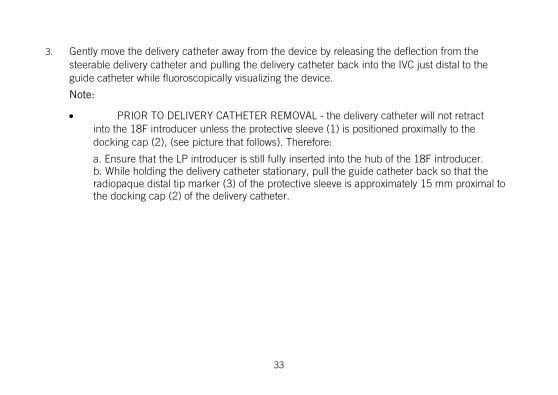
3. Gently move the delivery catheter away from the device by releasing the deflection from the steerable delivery catheter and pulling the delivery catheter back into the IVC just distal to the guide catheter while fluoroscopically visualizing the device.
Note:
• PRIOR TO DELIVERY CATHETER REMOVAL - the delivery catheter will not retract into the 18F introducer unless the protective sleeve (1) is positioned proximally to the docking cap (2), (see picture that follows). Therefore:
a. Ensure that the LP introducer is still fully inserted into the hub of the 18F introducer. b. While holding the delivery catheter stationary, pull the guide catheter back so that the radiopaque distal tip marker (3) of the protective sleeve is approximately 15 mm proximal to the docking cap (2) of the delivery catheter.
33

Figure 7. Protective sleeve is proximal to the docking cap
5. Pull the delivery catheter and guide catheter out as a unit visualizing them through the LP introducer.
6. Ensure that the protective sleeve and the delivery catheter docking cap are captured in the LP introducer.
7. Remove the LP introducer from the hub of the 18F introducer.
34

Reposition the Nanostim™ Leadless Pacemaker (If Necessary) Do not apply excessive forward force when affixing the device, because this could result in perforation. 1. Verify the Nanostim Leadless Pacemaker (LP) protective sleeve is pulled back as far as possible so
that the catheter has maximum flexibility (see pictures below).
Figure 8. LP protective sleeve pulled back for catheter flexibility
2. Gently advance and if necessary deflect the delivery catheter so it is coaxial with the docking button of the LP. Slowly pull back on the LP control knob until you hear an audible click and
35

visualize the LP mating with the delivery catheter. 3. Under fluoroscopy, slowly rotate the LP control knob counterclockwise and visualize the
fluoroscopic marker on the LP to ensure that the helix has rotated between two and three turns and has been totally disengaged from the endocardium.
CAUTION: Do not pull on delivery catheter until LP is fully disengaged. Do not apply excessive forward pressure, because perforation can occur.
4. Gently pull back the delivery catheter approximately 10 mm to verify disengagement of the device from the endocardium. Avoid excessive manipulation so the device helix remains in the lower septal area and away from any valve structures or chordae.
5. Advance the protective sleeve to fully cover the LP and the helix. 6. Verify the LP helix is fully captured by the LP protective sleeve. Repeat the steps in Implanting the
Nanostim Leadless Pacemaker (page 19).
Retrieve the Nanostim™ Leadless Pacemaker (If Necessary) Once the device is released from the delivery catheter it cannot be retrieved with the delivery catheter. To retrieve an implanted device, use either a Nanostim™ Retrieval Catheter - Triple Loop Snare or a Nanostim™ Retrieval Catheter - Single Loop Snare. Refer to their instructions for use.
36

Cremation of a Deceased Nanostim™ Leadless Pacemaker Patient It is not necessary to explant a Nanostim™ Leadless Pacemaker from a deceased adult patient prior to cremation, although the pacemaker should be removed if possible. Rupture of the device during cremation is normal, and is not expected to present a significant risk to surrounding life or property. Please carefully consider the following before proceeding with cremation: 1. Cremation should be limited to adults, and be conducted only if the device is within the intact
torso. 2. Cremation in an enclosed crematorium is preferred. If open-air cremation is conducted,
bystanders and inflammable materials must be kept back at least 10 meters (33 feet). 3. Following cremation, remove the device prior to further preparation of ashes.
Burial of a Deceased Nanostim™ Leadless Pacemaker Patient It is not necessary to explant a Nanostim™ Leadless Pacemaker from a deceased adult patient prior to burial, although the pacemaker should be removed and returned to St. Jude Medical if possible. The welded titanium enclosure is expected to remain hermetic following burial, and in the unlikely event of a breach, the volume of potentially offensive substances contained within the Nanostim™ Leadless Pacemaker is too small to present a significant risk to the surrounding environment.
Disposition of an Explanted Nanostim™ Leadless Pacemaker 1. Do not reuse explanted devices.
37

2. Clean explanted equipment with +1% sodium hypochlorite, rinse with water, dry. 3. Contact St. Jude Medical Technical Support for return instructions. All explanted and removed
devices should be returned and analyzed by St. Jude Medical, including those that have undergone cremation.
Disposal Dispose of the catheter and packaging following normal hospital procedures.
Patient Follow-Up Patients should be seen for follow-up per normal standard of care. If the patient experiences a spontaneous return of symptoms, it may be deemed appropriate for the patient to return for follow-up immediately.
Refer to Using the Nanostim™ Programmer Link Software (page 46) for information on programming the device.
A follow-up visit should include (at a minimum): Review of the summary screen Review of event markers and histograms Assessment of pacing, sensing, impedance and battery voltage. Confirmation that the final parameter settings are correct.
38

Progression or changes over time in the patient's underlying heart or systemic disease may necessitate a re-evaluation of the patient's clinical arrhythmias. Reprogramming of device parameters may be required. Device settings should be re-evaluated if the patient's antiarrhythmic medication is changed.
Depending on clinical circumstances and the patient's level of understanding, it may be advisable to provide the patient a magnet for emergency use.
Note: Patients with a Nanostim Leadless Pacemaker cannot be followed by trans-telephone monitoring (TTM).
LP follow-up without a Nanostim Programmer Link: If a Nanostim Programmer Link is not available, recommended replacement time (RRT) condition can be assessed using a standard pacemaker magnet. The magnet response is binary and will remain at 90 bpm until the device reaches recommended replacement time, when the magnet will pace at 65 bpm. See Magnet Response Mode (page 41).
Explanation of Pacemaker Function Subsections below provide descriptions of the following features: Pacing modes Programming Rate response Stored data
39

Event markers
Pacing Modes The device has programmable mode selections for permanent pacing modes, magnet response, and sensor operation. It also has reversion modes for magnet response and electromagnetic interference (EMI) response, and a rate-hysteresis function.
Programmable Mode Selections
Table 2. Programmable mode selections
Parameter Settings Notes
Mode VVI, VOO Permanent pacing modes. Sensor has no effect.
VVIR Sensor determines pacing rate and updates sensor-indicated rate histogram
VVIR passive Sensor updates sensor-indicated rate histogram without affecting pacing rate
40

Table 2. Programmable mode selections
Parameter Settings Notes
VVIR calibration Temperature data are stored every 20 seconds for one hour without affecting pacing rate (for example during a hall walk or treadmill test). Note: no pace, sense or sensor indicated rate histograms are available when in this mode
OFF Caution: LP provides no pacing
Magnet Mode ON Magnet causes VOO pacing at rate indicating cell status
OFF Magnet has no effect
At recommended replacement time (RRT), the device forces the Sensor setting to OFF.
Magnet Response Mode
If magnet mode is programmed ON, when the device detects a magnet, the device: Paces asynchronously (VOO mode) unless the mode was set to OFF. Paces at 100 min-1 for eight cycles. Paces at a test pulse rate of 90 min-1 before recommended replacement time (RRT); otherwise at
41

or after RRT it paces at a test pulse rate 65 min-1, for as long as it detects the magnet. Does not change pulse duration, pulse amplitude, and sensitivity, or emit an audible tone. The
device reverts to previously programmed parameters within 5 seconds following magnet removal.
The effectiveness of magnets varies. If one magnet does not cause magnet response, place a second magnet on top of the first or try a different magnet. Pressing firmly on the magnet to decrease the distance between the magnet and the pulse generator can also help.
EMI Reversion Mode
In the presence of continuous electromagnetic interference (EMI) in the R-wave sensing channel at a frequency ≥ 16 Hz, the device reverts to VOO mode at an interference pulse rate until the noise ceases. The interference pulse rate equals the programmed basic rate. The device implements this with a retriggerable refractory period of 78 ms included at the end of the programmed refractory period.
Rate Hysteresis Effect in VVI or VVIR Mode
If rate hysteresis is programmed to a value other than OFF, when a sensed event occurs, the pulse generator decreases the basic rate or the sensor-indicated rate by the rate hysteresis until the next paced event. This favors continuation of intrinsic activity.
If rate hysteresis is programmed to a value other than OFF, and search hysteresis is programmed to a value other than OFF, then after the programmed number of consecutive paced events, the pulse generator decreases the basic rate by the "rate hysteresis" for up to 8 paced events. This favors emergence of intrinsic activity.
42

Programming Considerations The device can be programmed with the Nanostim™ Programmer Link used in conjunction with the Merlin™ PCS. For more information on programming, refer to Using the Nanostim Programmer Link Software (page 46).
Refer to Pacemaker as Shipped and Reset Settings (page 90) and Pacemaker Programmable Parameters, Settings, and Tolerance (page 91).
Programming recommendations: VOO Mode is primarily intended for temporary diagnostic use. Competitive pacing can induce
potentially dangerous arrhythmias. Pulse amplitude: Determine the capture threshold before programming the pulse amplitude.
Program pulse amplitude to yield a suitable safety margin for reliable, long-term capture. Reassess capture thresholds periodically.
High-output settings: Programming high pulse amplitude, pulse width, and/or basic rate can reduce device longevity.
R sensitivity: To avoid potential complications associated with under-sensing, maintain a sensing margin of two to four times the intrinsic cardiac amplitude (for example, for an intrinsic signal of 4 mV, program the sensitivity to 1 or 2 mV). To avoid potential complications associated with over-sensing, use more sensitive settings, such as 1.0, and 1.5 mV, with caution, because such settings can cause the pacemaker to be more susceptible to electromagnetic interference (EMI)1.
At the end of a programming session, interrogate the device and confirm that final parameter
1 The pacemaker provides protection against EMI in conformance to international standard ISO 14117:2012 as modified for a leadless pacemaker.
43

settings are correct.
Rate-Responsive Modes The device provides a sensor-indicated rate in response to an increase in metabolic demand detected by a sensor that measures changes in right-ventricular blood temperature.
Refer to Programmable Mode Selections (page 40) for a description of mode configurations for rate response.
Rate-response programmable parameters: Sensor gain: A low gain setting results in a smaller increase in the sensor-indicated pacing rate in
response to a given temperature change, while a high gain setting results in a greater increase in pacing rate.
Max sensor rate: Maximum sensor-indicated rate.
Rate response non-programmable parameters: Exercise rate offset: The sensor-determined rate is increased by X min-1 when exercise is detected,
where X is determined by the following formula: X = (max sensor rate – basic rate) / 4.
Programming recommendations: Use caution when programming a high max sensor rate and long refractory period, because this
can leave little or no time for sensing intrinsic activity.
44
Stored Data The device stores data for display by the programmer. Device identification: including model code, serial number, and year of manufacture. Resettable diagnostic data: including histograms of pacing rate, sensing rate, and sensor-indicated
rate. Non-resettable diagnostic data: including event counters for pacing and sensing; date and time
when the device reached recommended replacement time (RRT); date and time resettable data were last cleared.
Measured data: including last requested measurement and trend over time for cell voltage; and a longevity prediction based on measured cell charge delivered since beginning of service, cell voltage, programmed settings, and event counters.
Patient data: patient identification.
Event Markers The device transmits event markers for display by the programmer: VP – Ventricular paced event VS – Ventricular sensed event
45

Using the Nanostim™ Programmer Link Software
Establish a Communications Link After the system has been set up according to the instructions for use, the programmer will attempt to establish a communications link with the implanted device. When the telemetry strength indicator is fully illuminated and markers are displayed, a communications link is fully established.
Telemetry Strength Indicator The telemetry strength indicator LEDs on the Merlin™ PCS show the quality of the communications link.
46

Figure 9. Telemetry strength indicator
1. Telemetry strength indicator
47

Table 3. Explanation of illuminated LEDs
Number of LEDs illuminated
Explanation
0 No LP has been detected or quality of communication with LP is poor. Significant baseline electromagnetic interference may exist or the patient cable may not be properly connected.
1 No LP has been detected or quality of communication with LP is poor. Signals are consistent with a low baseline electromagnetic interference and properly connected patient cable.
2 Quality of communication with LP is good. If good quality communication continues, additional LEDs will illuminate.
3 Quality of communication with LP is good. If good quality communication continues, additional LEDs will illuminate.
4 Quality of communication with LP is good. If good quality communication continues, additional LEDs will illuminate.
5 Consistent good quality communication with LP exists.
48

Markers When a good quality communications link is present as indicated by the telemetry strength indicators, the programmer begins to display markers: VS markers indicate ventricular sense events VP markers indicate ventricular pace events
49

Figure 10. Markers displayed
1. Marker display
50
Note:
If the device is programmed to Off mode, no markers will be displayed even if a good quality communications link is present. In this case, assess the communications link quality only by observing the state of the telemetry strength indicator.
Interrogating the Pacemaker When a communications link is fully established, the device may be interrogated by pressing the on-screen Interrogate button. Interrogating a new device initiates a programming session.
51

Figure 11. Communications link established
1. Interrogate button
52

Figure 12. Pacemaker values displayed
1. Parameter values 2. Interrogate button active
53

When the interrogation is complete, a programming session has been initiated. At this time other actions, such as assessing capture, taking measurements and programming, become available.
Assessing Capture To assess capture, navigate to the Capture tab on the Tests navigation panel.
54

Figure 13. Capture tab
1. Capture assessment functions are found on the Capture tab of the Tests navigation panel.
55

The base capture screen shows the current capture parameters. The current capture parameters can be adjusted using the on-screen buttons and pop-up menus.
56

Figure 14. The base capture screen
1. Current capture parameters 2. To open a pop-up menu, press
a parameter value button.
57

Figure 15. The Base Rate pop-up menu
58

When the base capture screen shows the desired parameters for capture assessment, initiate the assessment by pressing the Start button.
59

Figure 16. Start button on the Capture tab
1. To begin capture assessment, press the Start button.
60

When the Start button is pressed, the programmer commands the device to operate according to the capture screen parameter values. This temporarily overrides the permanent programming of the device (see Programming the Pacemaker (page 71)). When the capture assessment is stopped or if the programmer communications link is broken, the device returns to its permanently programmed parameter values.
After capture assessment has started, the Pulse amplitude Inc (increment) and Dec (decrement) buttons are active. Pressing one of these buttons increases or decreases the pulse amplitude to the next allowed setting.
61

Figure 17. Active Inc and Dec buttons
1. While capture assessment is active, Inc and Dec buttons are also active.
2. To end capture assessment, press the Stop button.
62
After capture assessment is complete, press the Stop button to return the device to its permanently programmed parameter values.
R-Wave Measurement To make an R-Wave measurement, navigate to the R-Wave tab on the Tests navigation panel and press the Update button.
63

Figure 18. R Wave tab
1. For R-Wave measurement, navigate to the R-Wave tab of the Tests navigation panel.
2. To retrieve an R-Wave measurement from the device, press the Update button.
64

During the R-Wave measurement the device will extend one pace interval to 2000 ms in an attempt to observe an intrinsic R-Wave with amplitude greater than the permanently programmed R-sensitivity threshold (see Programming the Pacemaker (page 71)). If an R-wave crosses this threshold, its amplitude is reported. If no R-wave was detected, "no R-wave" is reported instead.
Battery Voltage, Load Impedance and Estimated Time to RRT Measurement To retrieve the last battery voltage measurement from the device, to make a load impedance measurement, or to obtain an estimated longevity, navigate to the Battery and Electrode tab on the Tests navigation panel and press the appropriate Update button near the Battery Voltage, Load Impedance or Estimated time to RRT display.
65

Figure 19. Battery and Leads tab
1. Load Impedance, Battery Voltage and Estimated time to RRT measurements are found on the Tests navigation panel, Battery and Electrode tab.
2. To retrieve a measurement from the device, press one of the Update buttons.
66

To retrieve and display the last battery voltage measurement from the device, press the Battery Voltage Update button. To measure the device's electrode impedance, press the Load Impedance Update button. To obtain an estimated longevity, press the Estimated time to RRT button. The programmer displays the results of the measurement.
Rate Histograms To retrieve the rate histogram, navigate to the Histograms tab on the Diagnostic navigation panel and press the Update button.
67

Figure 20. Histogram tab
1. Rate histograms are found on the Histograms tab of the Diagnostic navigation panel.
2. To retrieve the rate histogram from the device, press the Update button.
68

The programmer retrieves and displays the rate histograms and indicates the percentage pacing and sensing since the histograms were last reset. The date and time of the last histogram reset is shown for reference.
To reset the histograms, press the Reset button. This will reset the histograms back to 0.
69

Figure 21. Reset button
1. To reset the device's histogram data, press the Reset button.
70

Programming the Pacemaker To program the device, navigate to the Parameters navigation panel.
71

Figure 22. Parameter navigation panel
1. To program the device, navigate to the Parameter navigation panel.
72

Review the displayed parameter settings. To change the value of a parameter, touch the panel where the parameter you want to change is displayed.
73
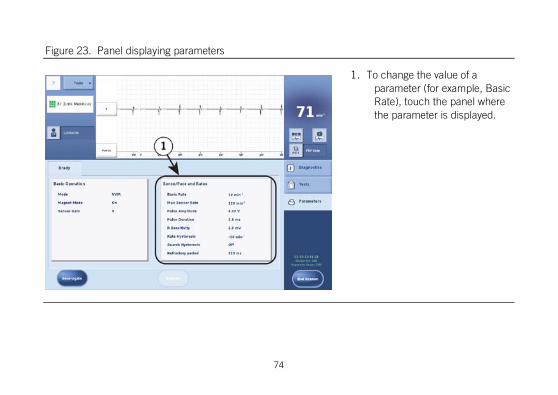
Figure 23. Panel displaying parameters
1. To change the value of a parameter (for example, Basic Rate), touch the panel where the parameter is displayed.
74
A panel sub-menu opens listing all the parameters from that panel. Press the value display of the parameter you want to change.
75
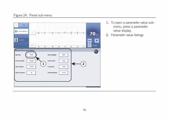
Figure 24. Panel sub-menu
1. To open a parameter value sub-menu, press a parameter value display.
2. Parameter value listings
76
A pop-up menu opens showing the allowed parameter value choices. Press one of the values to select it as the pending value. When you press a parameter value, the pop-up menu closes.
77

Figure 25. Pop-up menu
1. Press a new parameter value to select it and close the pop-up menu.
2. To close the pop-up menu without selecting a new parameter value, press the X button.
78

After you make a parameter value selection that is different from the one currently programmed in the device, that parameter value will be highlighted. When you are satisfied with the parameter values, press the X to close the panel sub-menu.
79

Figure 26. Highlighted parameter value
1. Pending programming is indicated by highlighted value parameter.
2. To close the panel sub-menu, press the X button.
80

Pending parameter value selections are also highlighted to indicate that programming changes have not yet been saved to the device.
81

Figure 27. Pending parameter value selections highlighted
1. Pending programming is indicated by a highlighted parameter value.
82

When you are satisfied with the pending parameters, press the Program button to program these parameter values to the device. After programming is successful, highlights are removed from the parameter values to indicate that there are no longer pending programming changes.
Ending a Programming Session When you are satisfied with the device's programming, press the End Session button. This will clear all pacemaker data from the programmer’s working memory and prepare it to enter a session with another device.
83
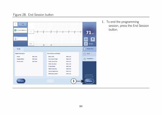
Figure 28. End Session button
1. To end the programming session, press the End Session button.
84

Medical Procedures In general, pacemaker patients should not be exposed to hospital equipment that produces high electromagnetic field strength signals, such as diathermy machines and electrosurgical units.
Contact Technical Support for additional information.
External defibrillation:
The electronic circuitry in the device provides protection from defibrillation discharges. Nevertheless, do not place defibrillator paddles directly over the device. Following defibrillation, ensure that the device is operating correctly.
Magnetic resonance imaging (MRI):
The Nanostim™ Leadless Pacemaker (LP) is conditionally safe for use in the MRI environment when used according to the instructions provided in the Nanostim™ MRI procedure manual.
CT Scans:
Due to their increased power levels and long exposure times, CT scans have the remote possibility of interfering with implanted devices. The potential interference is transient and occurs only when the X-ray signal is present. There is a remote possibility for a device to intermittently oversense while the CT scanning beam is directly over the implanted device.
Ionizing Radiation:
Therapeutic ionizing radiation (for example, used in linear accelerators and cobalt machines) can
85

permanently damage the pulse generator’s circuitry. The effect of ionizing radiation is cumulative; the potential for damage to the pulse generator is proportional to the patient’s total radiation dosage. If the patient must be exposed to ionizing radiation, protect the pulse generator during the procedure with local radiation shielding. Before and after exposure to radiation, evaluate the pulse generator operation to identify any adverse consequences.
Transcutaneous electrical nerve stimulation (TENS):
To reduce the possibility of interference with pacemaker function, place the TENS electrodes close to one another and as far from the pulse generator as possible. Before allowing unrestricted use of TENS in a home or other setting, screen the patient in a monitored environment for possible interaction.
Therapeutic diathermy:
Avoid diathermy, even if the device is programmed off, as it may damage tissue around the implanted electrodes or may permanently damage the pulse generator.
Electrosurgical cautery:
This can induce ventricular arrhythmias and/or fibrillation or may cause asynchronous or inhibited pulse generator operation. If use of electrocautery is necessary, the current path and ground plate should be kept as far away from the device as possible. The axis of the electrocautery should be perpendicular to the electrode axis. A bipolar cauterizer may minimize these effects. Following electrocautery, conduct a thorough assessment of the pulse generator.
RF ablation:
86

Delivery of intra-cardiac radiofrequency (RF) energy during an RF ablation procedure in patients with a cardiac implantable electronic device may cause any of the following: pacing above or below the programmed rate; reversion to asynchronous operation; device electrical reset; premature triggering of the elective replacement indicator, or permanent device malfunction and/or damage. RF ablation risks may be minimized by: programming an asynchronous non-rate responsive pacing mode prior to the RF ablation procedure; avoiding direct contact between the ablation catheter tip and the device; positioning the grounding patch/pad so that the current pathway does not pass through or near the device (for example, placing the ground plate under the patient’s buttocks or legs); having a programmer readily available; monitoring the patient during and immediately after the procdure; and/or having temporary pacing or external defibrillation equipment available.
Therapeutic ultrasound:
Do not use therapeutic ultrasound within 16 cm of the device.
Temporary pacing:
The Nanostim™ Leadless Pacemaker has not been tested with the use of a temporary pacemaker.
Patient Environments Patients should be directed to exercise reasonable caution in avoidance of strong electric or magnetic fields. If the pacemaker inhibits or reverts to asynchronous operation while in the presence of electromagnetic interference (EMI), the patient should move away from the EMI source or turn the
87

source off.
Advise patients to seek medical guidance before entering environments that could adversely affect the operation of the pulse generator, including areas protected by a warning notice preventing entry by pacemaker patients.
High-voltage transmission lines and equipment, arc or resistance welders, induction furnaces, and similar equipment may generate substantial EMI fields which may interfere with pulse generator operation.
Communication equipment such as microwave transmitters2, linear power amplifiers, or high-power amateur transmitters may generate sufficient EMI to interfere with pacemaker operation. Advise patients to move away from this equipment to resume normal pacemaker operation.
Home appliances that are in good working order and properly grounded do not usually produce enough EMI to interfere with pacemaker operation. Electric vibrators, razors, and hand tools held directly over the pacemaker may disturb pacemaker function.
Electronic article surveillance (EAS): Advise patients that EAS systems such as those at the point of sale and entrances/exits of stores, libraries, banks, etc., emit signals that may interact with pacemakers. It is very unlikely that these systems will interact with their device significantly. However, to minimize the possibility of interaction, advise patients to simply walk through these areas at a normal pace and avoid lingering near or leaning on these systems.
No-pacer symbol: Caution patients implanted with this device to avoid areas marked with the NO
2 Home appliance microwave ovens do not interfere with pulse generator operation.
88

PACER symbol.
Cellular telephones: Studies indicate there may be a potential interaction between cellular phones and pacemaker operation. When the phone is within six inches of the pulse generator, effects could include inhibition or asynchronous pacing. Any effects resulting from an interaction between cellular phones and implanted pacemakers are temporary. Moving the phone away from the device will return it to its previous state of operation. Because of the great variety of cellular phones and the wide variance in patient physiology, an absolute recommendation to cover all patients cannot be made. The following is a general guideline for patients with an implanted pulse generator who desire to operate a cellular phone: Maintain a minimum separation of six (6) inches between a hand-held cellular phone and the
implanted device. Portable and mobile cellular phones generally transmit at higher power levels compared to hand-held models. For phones transmitting above three watts, a minimum separation of 12 inches between the antenna and the implanted device is advised.
Patients should hold the phone to the ear opposite the side of the implanted device. Patients should not carry the phone in a breast pocket, or on a belt over or within six inches of the
implanted device as some phones emit signals only when they are turned on but not in use.
89
Storing the phone in a location opposite the side of the implant is recommended.
Specifications and Characteristics
Pacemaker As-Shipped and Reset Settings
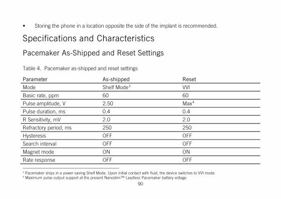
Table 4. Pacemaker as-shipped and reset settings
Parameter As-shipped Reset
Mode Shelf Mode3 VVI
Basic rate, ppm 60 60
Pulse amplitude, V 2.50 Max4
Pulse duration, ms 0.4 0.4
R Sensitivity, mV 2.0 2.0
Refractory period, ms 250 250
Hysteresis OFF OFF
Search interval OFF OFF
Magnet mode ON ON
Rate response OFF OFF
3 Pacemaker ships in a power-saving Shelf Mode. Upon initial contact with fluid, the device switches to VVI mode. 4 Maximum pulse output support at the present Nanostim™ Leadless Pacemaker battery voltage
90

Table 4. Pacemaker as-shipped and reset settings
Parameter As-shipped Reset • Sensor gain n/a n/c • Max sensor rate n/a n/c
n/a = not applicable
n/c = no change
Pacemaker Programmable Parameters, Settings, and Tolerances
Table 5. Pacemaker Programmable Parameters, Settings, and Tolerances
Parameter Settings Units Tolerance5
Mode VVI; VVIR; VVIR passive; VVIR calibration; VOO; OFF
- n/a
Basic Rate6 30; 40; 45; 50; 55; 60; 65; 70; 75; 80; 85; 90; 95; 100; 105; 110; 115; 120; 125; 130; 140; 150
min-1 2%
5 Parameter values are measured at 37 °C ± 2 °C and 500 Ω ± 1% load. 6 Refer to Intervals Corresponding to Rates for corresponding pulse intervals. The escape interval equals the pulse interval. In presence of continuous electromagnetic interference, the pacemaker operates at an interference pulse rate equal to the basic rate, refer to section EMI Reversion Mode. In presence of a magnet, the pacemaker operates at a test pulse rate, refer to section Magnet Response Mode.
91
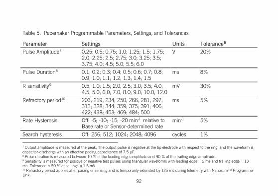
Table 5. Pacemaker Programmable Parameters, Settings, and Tolerances
Parameter Settings Units Tolerance5
Pulse Amplitude7 0.25; 0.5; 0.75; 1.0; 1.25; 1.5; 1.75; 2.0; 2.25; 2.5; 2.75; 3.0; 3.25; 3.5; 3.75; 4.0; 4.5; 5.0; 5.5; 6.0
V 20%
Pulse Duration8 0.1; 0.2; 0.3; 0.4; 0.5; 0.6; 0.7; 0.8; 0.9; 1.0; 1.1; 1.2; 1.3; 1.4; 1.5
ms 8%
R sensitivity9 0.5; 1.0; 1.5; 2.0; 2.5; 3.0; 3.5; 4.0; 4.5; 5.0; 6.0; 7.0; 8.0; 9.0; 10.0; 12.0
mV 30%
Refractory period10 203; 219; 234; 250; 266; 281; 297; 313; 328; 344; 359; 375; 391; 406; 422; 438; 453; 469; 484; 500
ms 5%
Rate Hysteresis Off; -5; -10; -15; -20 min-1 relative to Base rate or Sensor-determined rate
min-1 5%
Search hysteresis Off; 256; 512; 1024; 2048; 4096 cycles 1%
7 Output amplitude is measured at the peak. The output pulse is negative at the tip electrode with respect to the ring, and the waveform is capacitor-discharge with an effective pacing capacitance of 7.5 μF. 8 Pulse duration is measured between 10 % of the leading edge amplitude and 90 % of the trailing edge amplitude. 9 Sensitivity is measured for positive or negative test pulses using triangular waveforms with leading edge = 2 ms and trailing edge = 13 ms. Tolerance is 50 % at settings ≤ 1.5 mV. 10 Refractory period applies after pacing or sensing and is temporarily extended by 125 ms during telemetry with Nanostim™ Programmer Link.
92

Table 5. Pacemaker Programmable Parameters, Settings, and Tolerances
Parameter Settings Units Tolerance5
Magnet Mode On, Off - n/a
Rate Response • Sensor Gain • Max sensor rate
1-5 steps of 1 80-145 in 5 min-1 increments 150-170 in 10 min-1 increments
- min-1
n/a 3%
Non-Programmable Parameters Polarity: Pacing and sensing configurations in the Nanostim™ Leadless Pacemaker (LP) are non-programmable. The LP paces and senses from the distal electrode (tip) to the pacemaker housing (ring), similarly to a bipolar lead.
Pulse rate limit (runaway protection): Circuitry prevents delivery of pacing pulses at rates higher than 175 to 190 min-1. Pulse rate limit is measured at 37°C ± 2°C and 500 Ω ± 1% load.
Input Impedance: 50 to 150 kΩ.
Refer to Patient Follow-Up (page 38) for recommended methods for determining that the implanted
93

pacemaker is functioning properly.
Intervals Corresponding to Rates
Table 6. Intervals corresponding to rates
Rate (min-1)
Interval (ms)
Rate (min-1)
Interval (ms)
Rate (min-1)
Interval (ms)
30 2000 80 750 130 462
35 1714 85 706 135 444
40 1500 90 667 140 429
45 1333 95 632 145 414
50 1200 100 600 150 400
55 1091 105 571 155 387
60 1000 110 545 160 375
65 923 115 522 165 364
70 857 120 500 170 353
75 800 125 480 175 343
94

Pacemaker Power Source Information Many factors affect pulse generator service life, such as programmed parameters, percentage of time paced, load impedance, etc. Projected longevity is based on accelerated lithium-cell test data under certain conditions and does not account for such factors as sensor-driven pacing rate changes, effects of rate-limiting algorithms, the patient’s medical condition, or effects of a specific pacing prescription. Furthermore, these data are based on lithium cell life projections, which are approximations.
Device replacement can be achieved in several ways: Retrieve the first LP implant and implant a new LP implant Permanently disable the first implant with the Nanostim™ Programmer Link and implant a second
implant. Permanently disable the first implant with the Nanostim Programmer Link and implant a a
traditional pacemaker or ICD.
Permanently disabling the first LP implant is done with the Nanostim Programmer Link programmer via a password-protected screen in the Engineering tab of the Diagnostics navigation panel. Contact Technical Support for additional information on how to complete this step. If the patient is pacemaker dependent,consider using a temporary pacemaker to provide pacing support during the implant of the second device.
95

WARNING:
At recommended replacement time (RRT) the nominal life of the device is approximately six months. The device should be replaced expeditiously.
CAUTION: Do not implant a new traditional implant or new LP implant in close proximity to a permanently disabled LP implant, because the long-term mechanical and electrical interactions between devices potentially in contact with one another are not known. High output settings or high rates can shorten the time to RRT. High output and high rate settings can reduce the duration from RRT to end of service (EOS) to less than the nominal projected value. When the programmer indicates that the pacemaker has reached RRT, fully evaluate the device.
a. Characteristics of the power source:
Description: Eagle-Picher Medical Products custom lithium carbon-monofluoride (CFx) cell.
Usable capacity: 219 mAH, beginning of service (BOS) to recommended replacement time (RRT).
Estimated residual capacity at RRT: 29 mAH.
96

b. Current consumption at beginning of service, at pacing mode = VVIR, pulse amplitude = 2.5 V, pulse duration = 0.4 ms, basic rate = 60 min-1, pacing load = 600 Ω, sensor status = On.
Inhibited: 0.6 μA
100% pacing: 2.6 μA
c. Projected service life, at pacing mode = VVIR, pulse duration = 0.4 ms, basic rate = 60 min-1, pulse amplitude = 2.5 V
97

% Pacing 500 ohm load 600 ohm load
100 8.8 yr 9.8 yr ‡
75 10.6 yr 11.7 yr
50 13.3 yr 14.5 yr
25 17.9 yr 18.9 yr
‡ pulse amplitude of 5.0 V results in 2.9 yr projected service life.
d. Power source indicator at recommended replacement time (RRT): When the LP detects a magnet, the pacemaker:
Paces asynchronously (VOO mode) unless the mode was set to Off.
Paces at 100 min-1 for 8 cycles.
Paces at 90 min-1 before RRT; otherwise at or after RRT it paces at 65 min-1, for as long as it detects the magnet.
98

Does not change pulse duration, pulse amplitude, and sensitivity.
The LP reverts to previously programmed parameters within 5 seconds following magnet removal. e. Prolonged service period, at pacing mode = VVI, pulse duration = 0.4 ms, basic
rate = 60 min-1, pulse amplitude = 2.5 V, percent pacing = 100%, pacing load = 600 Ω:
9.2 months, RRT to end of service (EOS).
An estimate of longevity is provided based on calculations based on:
Previous programmable pacemaker settings,
Current programmable pacemaker settings,
Historical sensor indicated rate,
Historical percentage of pacing and sensing,
Patient load.
The calculation is made at the start of every session and whenever a programming change affects the estimate.
99
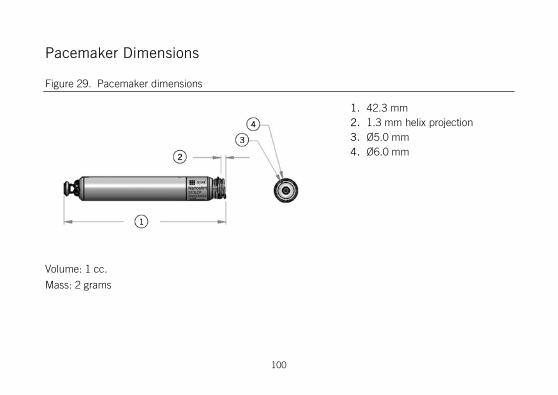
Pacemaker Dimensions
Figure 29. Pacemaker dimensions
1. 42.3 mm 2. 1.3 mm helix projection 3. Ø5.0 mm 4. Ø6.0 mm
Volume: 1 cc.
Mass: 2 grams
100
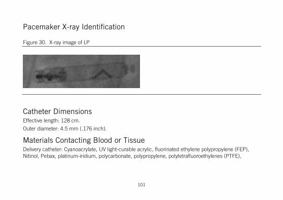
Pacemaker X-ray Identification
Figure 30. X-ray image of LP
Catheter Dimensions Effective length: 128 cm.
Outer diameter: 4.5 mm (.176 inch).
Materials Contacting Blood or Tissue Delivery catheter: Cyanoacrylate, UV light-curable acrylic, fluorinated ethylene polypropylene (FEP), Nitinol, Pebax, platinum-iridium, polycarbonate, polypropylene, polytetrafluoroethylenes (PTFE),
101

polyvinyl chloride (PVC), silicone, stainless steel, and high-density polyethylene (HDPE).
Pacemaker: MP-35NLT, nickel-titanium (Nitinol), nylon, titanium, titanium-aluminum-vanadium, titanium nitride, platinum-iridium, poly-ether-ether-ketone (PEEK), poly(para-xylylene), and silicone rubber.
Pacemaker Electrodes The tip electrode is a titanium-nitride coated platinum-iridium disc located at the center of the fixation helix, with a geometric surface area of 2 mm2. The tip electrode includes 0.1 to 0.7 mg of dexamethasone sodium phosphate, intended to reduce inflammation. The ring electrode is the uncoated part of the titanium pacemaker case, with a geometric surface area >500 mm2. The inter-electrode distance is >10 mm. The maximum depth of penetration of the fixation mechanism in tissue is 1.3 mm.
The conductor resistance connecting the electrodes to the circuit (analogous to lead conductor resistance) is 25 Ω maximum. Electrode pacing impedance is 250 to 2000 Ω. Electrode sensing impedance is 10 KΩ maximum.
Technical Support St. Jude Medical maintains 24-hour phone lines for technical questions and support: 1 818 362 6822 1 800 722 3774 (toll-free within North America)
102

+ 46 8 474 4147 (Sweden)
For additional assistance, call your local St. Jude Medical representative.
Symbols
Table 7. Symbols
Symbol Description
Single-chamber, ventricular rate modulated pacing
Contents quantity
Do not reuse
Serial number
Use by
103

Table 7. Symbols
Symbol Description
Date of Manufacture
Manufacturer
Do not use if package is damaged
Keep dry
Do not resterilize
The device contains a battery and the label is affixed to this device in accordance with European Council Directive 2006/66/EC. Return the device to St. Jude Medical when explanted or dispose as potentially biohazardous material in accordance with medical practice and applicable local, state, and federal laws and regulations.
104

Table 7. Symbols
Symbol Description
Temperature limitations
Reorder number
Batch code
Authorized Representative in the European Community
Keep away from sunlight
Consult instructions for use
Follow instructions for use on this website
105

Table 7. Symbols
Symbol Description
Sterilized using ethylene oxide
Affixed in accordance with European Council Directive 90/385/EEC. Hereby, St. Jude Medical declares that this device is in compliance with the essential requirements and other relevant provisions of these Directives.
Made in USA
User's manual
Device has been demonstrated to pose no known hazards in a specified MRI environment with specified conditions of use.
106

Table 7. Symbols
Symbol Description
MR environment and conditions specified for MR Conditional use: • Magnet strength: 1.5 Tesla • Scan regions: Whole body • SAR (specific absorption rate) ≤4 W/KG For a complete set of conditions and environments, see the MRI Procedure Information document.
Open pouch from corner.
Right-ventricular amplitude and pulse width
Right-ventricular sensitivity
Ventricular refractory period
Basic rate
107

Table 7. Symbols
Symbol Description
Steroid-eluting
Bipolar pacing
Bipolar sensing
Sensor: Core temperature
108

CE Mark Date
Table 8. Year in which the CE mark was awarded.
Model Year
S1DLCP 2013
109


Manufacturer: St. Jude Medical 15900 Valley View Court Sylmar, CA 91342 USA +1 818 362 6822
European Authorized Representative: St. Jude Medical Coordination Center BVBA The Corporate Village Da Vincilaan 11 Box F1 1935 Zaventem Belgium +32 2 774 68 11
sjm.com
January 2016 ARTEN100129559 Rev. C