nanoarchitectured graphene-based supercapacitors for next
TRANSCRIPT

HAL Id: hal-02045769https://hal.archives-ouvertes.fr/hal-02045769
Submitted on 22 Feb 2019
HAL is a multi-disciplinary open accessarchive for the deposit and dissemination of sci-entific research documents, whether they are pub-lished or not. The documents may come fromteaching and research institutions in France orabroad, or from public or private research centers.
L’archive ouverte pluridisciplinaire HAL, estdestinée au dépôt et à la diffusion de documentsscientifiques de niveau recherche, publiés ou non,émanant des établissements d’enseignement et derecherche français ou étrangers, des laboratoirespublics ou privés.
Nanoarchitectured Graphene-Based Supercapacitors forNext-Generation Energy-Storage Applications
Rahul R. Salunkhe, Ying-Hui Lee, Kuo-Hsin Chang, Jing-Mei Li, PatriceSimon, Jing Tang, Nagy L. Torad, Chi-Chang Hu, Yusuke Yamauchi
To cite this version:Rahul R. Salunkhe, Ying-Hui Lee, Kuo-Hsin Chang, Jing-Mei Li, Patrice Simon, et al.. Nanoarchitec-tured Graphene-Based Supercapacitors for Next-Generation Energy-Storage Applications. Chemistry- A European Journal, Wiley-VCH Verlag, 2014, 20 (43), pp.13838-13852. �10.1002/chem.201403649�.�hal-02045769�

OATAO is an open access repository that collects the work of Toulouse researchers and makes it freely available over the web where possible
Any correspondence concerning this service should be sent to the repository administrator: [email protected]
This is an author’s version published in: http://oatao.univ-toulouse.fr/21783
To cite this version:
Salunkhe, Rahul R. and Lee, Ying-Hui and Chang, Kuo-Hsin and Li, Jing-Mei
and Simon, Patrice and Tang, Jing and Torad, Nagy L. and Hu, Chi-Chang and
Yamauchi, Yusuke Nanoarchitectured Graphene-Based Supercapacitors for
Next-Generation Energy-Storage Applications. (2014) Chemistry - A European
Journal, 20 (43). 13838-13852. ISSN 0947-6539
Official URL: https://doi.org/10.1002/chem.201403649

& Nanomaterials
Nanoarchitectured Graphene-Based Supercapacitors for Next-Generation Energy-Storage Applications
Rahul R. Salunkhe,[a, b] Ying-Hui Lee,[b] Kuo-Hsin Chang,[b] Jing-Mei Li,[b] Patrice Simon,[c]
Jing Tang,[a, d] Nagy L. Torad,[a, d] Chi-Chang Hu,*[b] and Yusuke Yamauchi*[a, d]
DOI: 10.1002/chem.201403649

Abstract: Tremendous development in the field of portableelectronics and hybrid electric vehicles has led to urgent andincreasing demand in the field of high-energy storage de-vices. In recent years, many research efforts have been madefor the development of more efficient energy-storage de-vices such as supercapacitors, batteries, and fuel cells. In par-ticular, supercapacitors have great potential to meet the de-mands of both high energy density and power density inmany advanced technologies. For the last half decade, gra-phene has attracted intense research interest for electrical
double-layer capacitor (EDLC) applications. The unique elec-tronic, thermal, mechanical, and chemical characteristics ofgraphene, along with the intrinsic benefits of a carbon mate-rial, make it a promising candidate for supercapacitor appli-cations. This Review focuses on recent research develop-ments in graphene-based supercapacitors, including dopedgraphene, activated graphene, graphene/metal oxide com-posites, graphene/polymer composites, and graphene-basedasymmetric supercapacitors. The challenges and prospectsof graphene-based supercapacitors are also discussed.
1. Introduction
Syntheses of various graphene materials with different shapesand the graphene composites have attracted considerable at-tention in development of energy-storage systems such as su-percapacitors, batteries, and fuel cells. Currently, the develop-ment of cost-effective, maintenance-free, highly efficient, andenvironmentally friendly energy storage systems is becomingincreasingly demanding. Among the various energy storagedevices, supercapacitors are very attractive due to their highspecific power (>10 kW kg�1) and moderate specific energy(�10 W h kg�1).[1] These characteristics generally meet thegrowing demand for time-dependent electric power systemsfor portable electronics, hybrid electric vehicles (HEVs), powertools, stop-and-go systems, and others.[2] Consequently, design-ing a powerful energy-storage/delivery system with electro-chemical capacitors (ECs) and developing next-generation ECswith much higher specific power and energy have become at-tractive research topics.
The applications of ECs in modern life can generally be di-vided into three types according to the power-supportingmodes. As shown in Figure 1 a, ECs have been used in digitalcommunication systems requiring pulses in milliseconds aswell as in power tools and office machines with a peak-powertime in seconds due to the unusual pulse–power property, ac-ceptable energy density, and very long charge–discharge lifecycle for ECs. Figure 1 b shows how ECs can efficiently capture
and level fluctuating electricity generated from solar cells andwind power systems because of their relatively low equivalentseries resistance (ESR), which significantly reduces the electrici-ty loss and heat generation during the charging process. Asclearly demonstrated in Figure 1 c, ECs provide an immediatepower supply and recovery ability due to the ultrahigh reversi-bility of the CD process on electrode materials. Therefore, ECshave been considered as important energy-capture devices toincrease the energy efficiency and save electricity in any go-and-stop systems, such as HEVs/EVs, load cranes, mass rapidtransit (MRT), and elevators. In addition, EC researchers aim toincrease energy and power densities, as well as lower fabrica-tion costs by using environmentally friendly materials, for theincreasingly important applications of ECs in power-manage-ment systems (e.g. , smart grids).
The capacitance of supercapacitors generally comes fromtwo energy-storage mechanisms: the electrical double-layercharge/discharge process and surface redox reactions of elec-troactive materials, which are used in the so-called EDLCs and(redox) pseudocapacitors, respectively.[3] In current EDLCs,carbon-based materials (such as activated carbon, AC) withhigh surface area have been mostly utilized as the electrodes.
Figure 1. Typical power-supporting modes combined with ECs for variousapplications: a) power supply in the pulse/peak mode, b) efficient electricityleveling/capturing in electricity storage, and c) immediate power supply andrecovery mode for stop-and-go systems.
[a] R. R. Salunkhe, J. Tang, N. L. Torad, Prof. Dr. Y. YamauchiWorld Premier International (WPI)Research Center for Materials Nanoarchitectonics (MANA)National Institute for Materials Science (NIMS)1–1 Namiki, Tsukuba, Ibaraki 305-0044 (Japan)E-mail : [email protected]
[b] R. R. Salunkhe, Y.-H. Lee, K.-H. Chang, J.-M. Li, Prof. Dr. C.-C. HuLaboratory of Electrochemistry and Advanced MaterialsDepartment of Chemical Engineering, National Tsing Hua UniversityHsin-Chu 30013 (Taiwan)E-mail : [email protected]
[c] P. SimonCIRIMAT Laboratory (UMR CNRS 5085)Department of Material Science, Universit� Paul Sabatier, Toulouse (France)
[d] J. Tang, N. L. Torad, Prof. Dr. Y. YamauchiFaculty of Science and Engineering, Waseda University3-4-1 Okubo, Shinjuku, Tokyo 169-8555 (Japan)

The major contribution for the capacitance values comes fromthe charge accumulated at the electrode/electrolyte interface.Nanoporous carbons with high surface area are achievedthrough carbonization of metal–organic frameworks (MOFs) orporous coordination polymers (PCPs).[4] The resultant nanopo-rous carbons exhibit high electrochemical capacitances in anacidic aqueous electrolyte.[5] In contrast, a pseudocapacitoruses conducting polymers[6] or metal oxides[7] as an electrodematerial, which undergoes highly reversible Faradic redox reac-tions for electroactive species. Conducting polymers (e.g. , poly-aniline[6a, 8] and polypyrrole[6b]) and metal oxides (e.g. , RuO2,MnO2, NiO, and In2O3) have been shown to exhibit high pseu-docapacitance but poor stability during charge–discharge cy-cling with the exception of RuO2- and MnO2-based materials.[9]
Nickel and cobalt hydroxides with various shapes also exhibithigh potential as novel electrochemical pseudocapacitors.[10] Itis generally known that the typical charge–discharge times forpseudocapacitors are significantly longer than those of EDLCs.Carbon materials, such as activated carbons (ACs) and carbonnanotubes (CNTs), usually exhibit good stability but limited ca-pacitance values. It is clear that EDLCs processes are surfacephenomena, and hence the CD performance greatly dependson the electrolyte-accessible surface area. The micropores incarbon materials are inaccessible by the electrolyte, resultingin the inability of the double layer to form in the pores. Thisresult leads to a decrease in the capacitance value (10–20 % ofthe ‘theoretical’ capacitance) of ACs. Good electrical conductiv-ity, high chemical and mechanical stability, and an optimizednanostructure are also other important factors that are respon-sible for achieving high capacitance values. In spite of the typeof the charge storage mechanism, carbon-based materials arethe most common materials for supercapacitor applicationsbecause of their outstanding properties such as their nontoxicnature, high electrical, chemical, and strong mechanical prop-erties, and environmental friendliness, etc. The potential win-dows in nonaqueous electrolytes are generally larger thanthose obtained in aqueous media, although the overpotentialof hydrogen evolution on carbons is high, especially in neutralelectrolytes.
Recently, graphene has become a main research focus in thedevelopment of high-performance supercapacitors.[11] Gra-phene is an atomically thick, two-dimensional (2D) sheet con-sisting of sp2-carbon atoms in a honeycomb network of six-member rings.[12] This material can be considered to be thebasic unit for building all graphitic materials in various forms,such as zero-dimensional (0D) fullerenes, one-dimensional (1D)CNTs, and three-dimensional (3D) graphite (stacked graphenesheets). Besides this, graphene has shown high electrical con-ductivity, mechanical strength, and optical absorption proper-ties that are clearly different from those of ACs, CNTs, and ful-lerenes, leading to the high research interest in physics andchemistry.[13] Other characteristics of graphene are its excep-tionally high specific surface area of over 2600 m2 g�1, sufficientporosity, superior conductivity, a broad potential window, andrich surface chemistry.[1a, 14] The major contributors to the spe-cific surface area of graphene are not only the lateral sizes andtheir distribution in the solid state, but also the open porosity
created between the graphene nanosheets. Because of theseproperties, graphene-based materials have been developed forhigh-power and high-energy supercapacitors, in order to cir-cumvent the limitations to the power capability of supercapa-citors caused by electrode kinetics, such as limited ion trans-port in the confined ultra-micropores of AC.
There have been several recent reviews on graphene-basedelectrode materials,[11, 15] but at present there are no reviews fo-cusing on certain important aspects, including the use of dif-ferent dopants in graphene, the activation of graphene, as wellas the use of graphene oxide for asymmetric supercapacitorapplications. Thus, in this Review, we briefly address these as-pects of the development of next-generation graphene super-capacitor electrodes. Also, a brief summary of recent progressin graphene-based electrode materials for supercapacitor ap-plications is presented, including reduced graphene, activatedgraphene, doped graphene, graphene/metal oxide composites,graphene/polymer composites, and others. Their advantagesand disadvantages are compared and summarized accordingto the literature available to date.
Chi-Chang Hu received his bachelor’s degree in1991 and Ph.D. in the Department of ChemicalEngineering from National Cheng Kung Uni-versity in 1995. After receiving his Ph.D., heworked at National Chung Cheng University asan assistant professor (1997), an associateprofessor (2000), and a full professor (2003). Hejoined National Tsing Hua University in 2007and is presently working as a distinguishedprofessor at the Department of ChemicalEngineering, National Tsing Hua University.He has published about 200 SCI publicationswith the total number of citations more than6200 and has an h-index of 41. He concur-rently serves as an editorial board member for the Journal of the TaiwaneseInstitute of Chemical Engineers (indexed by SCI), an editorial advisory boardmember in the Open Electrochemistry Journal (indexed by SCI), and an editorialadvisory board member in the International Journal of Electroactive Materials.His current research projects include the design of nanostructured materials forapplications in supercapacitors, metal–air batteries, rechargeable metal–airbatteries, organic electro-photocatalytic degradation, and solar water splitting.
Yusuke Yamauchi received his bachelor’sdegree in 2003, master’s degree in 2004, andPh.D. in 2007 from Waseda University inJapan. After receiving his Ph.D., he joinedNIMS as permanent staff. Since 2008, hestarted his own research group ’Inorganicmaterials laboratory’. He has published morethan 300 papers in international refereedjournals with more than 5500 citations. Heconcurrently serves as visiting professor atseveral universities (Tianjin University in China,Waseda University in Japan), an associateeditor of APL Materials published by theAmerican Institute of Physics (AIP), and aneditorial board member of Scientific Reports published by the Nature PublishingGroup (NPG). His major research interest is tailored design of novel nanoporousmaterials with various shapes and compositions toward practical applications.
2. Electrode Materials Based on Graphene
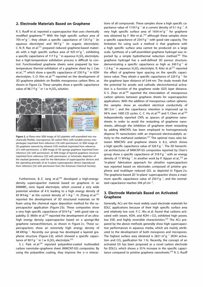
R. S. Ruoff et al. reported a supercapacitor that uses chemicallymodified graphene.[16] With the high specific surface area of705 m2 g�1, they obtain a specific capacitance of 135 F g�1 (inaqueous electrolyte) and 99 F g�1 (in organic electrolyte).C. N. R. Rao et al.[17] prepared reduced graphene-based materi-als with a high specific surface area of 925 m2 g�1, exhibitinga specific capacitance of 117 F g�1 in aqueous H2SO4 electrolyte,but a high-temperature exfoliation process is difficult to con-trol. Functionalized graphene sheets were prepared by low-temperature thermal exfoliation of a graphene sheet by J. Caoet al. ,[18] which show a specific capacitance of 230 F g�1 in KOHelectrolytes. S. O. Kim et al.[19] reported on the development of3D graphene platelets on flexible mesoporous carbon films, asshown in Figure 2 a. These samples show a specific capacitancevalue of 86.7 F g�1 in 1 m H2SO4 solution.
Furthermore, B. Z. Jang et al.[20] developed a high-energy-density supercapacitor material based on graphene in anEMIMBF4 ionic liquid electrolyte, which covered a very widepotential window of 4 V, leading to a high energy density of85 W h kg�1 at the current density of 1 A g�1. H. Zhang et al.[21]
reported the development of 3D structured materials on Nifoam using the chemical vapor deposition method for the su-percapacitor application (Figure 2 b). These composites showa very high specific capacitance of 816 F g�1 with good rate ca-pability. D. Mitlin et al.[22] reported the development of an ultra-high energy density supercapacitor based on a sponge-likegraphene nanoarchitecture, as shown in Figure 2 c. These su-percapacitors show an extremely high energy density of48 kW kg�1. Recently, our group has developed a layered gra-phene structure (Figure 2 d), which showed a specific capaci-tance of 90 F g�1 in 1 m H2SO4 electrolyte.[23]
S. J. Park et al.[24] reported polyaniline-coated multiwalledcarbon nanotube–graphene sheet (MWCNT-GS) composites. Byusing the polyaniline coating, they improve the p–p interac-
tions of all compounds. These samples show a high specific ca-pacitance value of 1118 F g�1 at a current density of 0.1 A g�1. Avery high specific surface area of 1654 m2 g�1 for graphenewas obtained by F. Wei et al. ,[25] although these samples showa specific capacitance of 254 F g�1 with good rate capacity. Thelimitation for using such a method is that graphene witha high specific surface area cannot be produced on a largescale. Synthesis of a self-assembled graphene hydrogel was re-ported by a simple hydrothermal reduction method.[26] Thisgraphene hydrogel has a well-defined 3D porous structure,demonstrating a specific capacitance as high as 240 F g�1 at1.2 A g�1 in aqueous H2SO4 electrolyte. R. Kçtz et al.[27] reportedthe effect of graphene layer spacing on the specific capaci-tance value. They obtain a specific capacitance of 220 F g�1 forthe graphene layer distance of 0.44 nm. The study reveals thatthe potential for anodic and cathodic electrochemical activa-tion is a function of the graphene oxide (GO) layer distance.X. S. Zhao et al.[28] reported the intercalation of mesoporouscarbon spheres between graphene sheets for supercapacitorapplications. With the addition of mesoporous carbon spheres,the samples show an excellent electrical conductivity of381 S m�1, and the capacitance retention is improved up to94 % over 1000 CD cycles. C. C. Hu et al.[29] and Y. Chen et al.[30]
independently reported CNTs as spacers of graphene nano-sheets in order to avoid the restacking of graphene nano-sheets, although the inhibition of graphene sheet restackingby adding MWCNTs has been employed to homogeneouslydisperse Pt nanoclusters with an improved electrocatalytic ac-tivity to the methanol oxidation.[31] The optimal mass ratio be-tween MWCNTs and graphene sheets is 8:2, which showsa high specific capacitance value of 326 F g�1. The 3D hierarchi-cal architectures of MWCNT-GS composites reported by Chen’sgroup show a specific capacitance of 318 F g�1 with an energydensity of 11 W h kg�1. In another work by P. Ajayan et al. ,[32] an‘in-plane’ fabrication approach for ultrathin supercapacitorswas reported based on electrodes composed of pristine gra-phene and multilayer reduced GO, as depicted in Figure 2 e.The graphene-based 2D ‘in-plane’ supercapacitor shows a maxi-mum specific capacitance value of 250 F g�1, and the normal-ized capacitance reaches 394 mF cm�2.
3. Electrode Materials Based on ActivatedGraphene
Generally, ACs are the most widely used electrode materials forEDLC applications because of their high specific surface areaand relatively low cost. F. C. Wu et al. found that carbons acti-vated with steam, KOH, and KOH + CO2 exhibited high power,low ESR, and highly reversible characteristics.[33] The ACs pre-pared by the above methods generally show high supercapaci-tive performances in aqueous media, which are mainly attrib-uted to the development of both mesopores and micropores.The highest surface area obtained is 2821 m2 g�1 (KOH activa-tion and CO2 gasification for 1 h). Recently, the concept of anactivated GS has been proposed as a novel carbon electrodefor EDLCs, which shows a 35 % increase in the specific capaci-tance compared to pristine graphene nanosheets.[34] R. S. Ruoff
Figure 2. a) Plane-view SEM image of GO platelets self-assembled into me-chanically flexible, macroporous 3D carbon films with tunable porous mor-phologies (reprinted from reference [19] with permission). b) SEM image of3D graphene network by ethanol–CVD method (reprinted from reference[21] with permission). c) SEM image of 3D sponge graphene (reprinted fromreference [22] with permission). d) SEM image of layered graphene structure(reprinted from reference [23] with permission). e) Schematic depiction ofthe stacked geometry used for the fabrication of supercapacitor devices andthe operating principle of an in-plane supercapacitor device (reproducedfrom reference [32] with permission from the American Chemical Society).

et al. reported that the specific surface area of the GS preparedby microwave exfoliation of GO was significantly enhanced to3100 m2 g�1 after activation by KOH.[35] The schematic diagramfor the chemical activation of graphene with KOH is shown inFigure 3. In this activated GS, there are large amounts of 0.6 to5 nm wide pores in the highly curved, thin, sp2-bonded carbonwalls.
The activation treatment of an agglutinate GS not only in-creases its specific surface area but also creates short micro-pore channels that are significantly shorter than those in largeAC particles. Therefore, an EDLC fabricated with activated GSelectrodes exhibits excellent, high-power performance. For ex-ample, the activated GS-based EDLC maintains a rectangle-likeCV behavior at a scan rate as high as 500 mV s�1 in an organicelectrolyte. In addition, this device also possesses an energydensity of 70 W h kg�1 and power density of 75 kW kg�1, whichare one order of magnitude higher than the values of AC-based EDLCs. Therefore, activated graphene sheets will makesuperior supercapacitors for energy storage in the future.
4. Electrode Materials Based on Graphene withHeteroatoms
The heteroatom doping of carbon materials has been demon-strated to give unique physicochemical properties, leading tosuperior capacitive performances by the change in electronicstates of the graphene layer or the additional introduction ofpseudocapacitance. The doping of different atoms, such asB,[36] N,[37] P,[38] and S,[39] into the carbon framework and the co-doping of these atoms[40] have been reported so far. The incor-poration of B and N is more widely investigated, especiallythat of N; however, fewer studies show the effects of P and Son the carbon electrodes for EDLCs, because the larger size ofthese atoms limits their presence on the surface or edge ofgraphene as surface functional groups. On the other hand,since carbons are susceptible to oxidation during differentpreparation methods or treatments, surface oxygen-containingfunctional groups are ubiquitous and inevitable in almostevery carbon material. Thus, oxygen incorporation is not in-cluded as a separate section in the following discussion.
4.1. Boron doping
The early B-incorporated carbons were obtained under a harshenvironment. Boron was mixed with the carbon precursor andsubject to extremely high temperatures (ca. 1800–3000 8C) to
achieve doping in the graphitic structure through the diffusionof boron at such high temperatures.[36a, 41] The high-tempera-ture preparation leads to the formation of substituted B (188–189 eV), a B4C structure (graphite-like structure, 186–187 eV),and B2O3 (192.5–193.5 eV).[36a, 42] Recently, the carbonization ofprecursors employing either organic or organic/inorganic tem-plates for B-doped carbons has also been reported, whichform B�C (185–187 eV), B�O�C (192–192.2 eV), and B�O (191–193 eV).[36b, 38b, 43] In such self-assembly systems, boron is shownto prevent shrinkage of the templates and preserve the meso-porous structure to maintain the high specific surface area ofthe carbon materials.[38b, 43] Compared to the extremely hightemperature treatment that leads to a limited amount ofboron (with the maximum of 2.5 at % doping at 2500 8C[44]),the B-impregnation during carbonization involving templatesresults in a boron content of up to 14 at %.[45]
The heteroatom doping of carbon materials will influence (a)the surface electronic states (i.e. , double-layer capacitance), (b)the electric conductivity (i.e. , capacitance retention), and (c)the types and amounts of functional groups on or within thegraphene layers (i.e. , pseudocapacitance). Accordingly, we dis-cuss the effects of B doping in the following from the threeperspectives.
The capacitance of EDLCs can be expressed by Equa-tion (1)[46]:
1C¼ 1
CSCþ 1
CHþ 1
Cdiffð1Þ
in which CSC is the space charge capacitance of the solid, CH
represents Helmholtz double-layer capacitance, and Cdiff is thecapacitance of the diffuse layer; the latter two belong to theelectrolyte capacitance. Although the capacitance of an EDLCis usually determined by the high specific surface area ofcarbon materials, the capacitance would be limited when thesurface area reaches 1200 m2 g�1.[47] The charge accommoda-tion is restricted by the space constriction, especially for micro-porous carbon materials; that is, the capacitance is limited bythe space charge capacitance of the solid. On the other hand,in concentrated electrolytes, Cdiff is much larger than CH, result-ing in a negligible value of Cdiff
�1. The value of CH can be esti-mated to be 20 mF cm�2 for carbon materials in the absence ofspecific adsorption,[41] but the value of CSC is relatively small-er,[48] establishing the dominant role of space charge capaci-tance for the measured capacitance considering the reciprocalsof CSC and CH. The incorporation of boron has been demon-strated to enhance space charge capacitance to provide highercapacitance.[36, 41] The substituted boron in the carbon frame-work would increase the number of holes as charge carriersdue to its p-type characteristics, leading to the increase incharge carriers or the DOS (density of states) change at theFermi level.[36, 49] Then, the space charge capacitance is en-hanced.[36, 49] The influence of boron on the double-layer capac-itance was further explored by a density functional theory(DFT) study on the zigzag edges of doped graphene nanorib-bons (ZGNR) to reveal the ability of charge carriers to absorb
Figure 3. A scheme shows the microwave exfoliation/reduction of GO andthe following chemical activation of GO with KOH. MEGO = microwave-exfo-liated graphene oxide.
onto the B-doped carbons. The results showed that the largercritical distance for proton binding is obtained in comparisonwith N- and O-doped edges,[50] indicating easier proton bind-ing on B-doped ZGNR, which correlates well with the higherinterfacial capacitance for B-doped carbons reported in previ-ous literature.[36, 41] In addition, the maximum proton bindingonto the substituted ZGNR was demonstrated to follow therule of [8-n-1] , where n represents the number of valence elec-trons of the substituted atom on the adsorption edge site.[51]
Hence, among B-, N-, and O-doped ZGNRs, maximum protonloading can be achieved with boron substitution, further es-tablishing the ability of B doping to enhance the interfacialcapacitance.
Since B doping increases charge carrier concentration, theintrinsic electric conductivity of the doped carbons can be en-hanced, leading to smaller ESR, which improves the capaci-tance retention during a fast charge–discharge process.[38b, 41, 43]
The graphitic crystallinity (i.e. , electric conductivity) grows asthe concentration of B doping increases under extremely hightemperature treatments, but only limited B doping can be ach-ieved.[44] The capacitance retention is also determined by theporous structure of the electrodes. Ordered mesoporous struc-tures fabricated by templates have been shown to be benefi-cial for electrolyte diffusion to promote capacitance reten-tion.[36b, 38b, 40c, 43] However, B doping introduces boron as defectsin the ordered porous structure, increasing the charge trans-portation resistance for electrolytes in the pores. Consequently,the amount of B doping should be optimized for good electricconductivity while preventing the deterioration of the orderedporous structure for good capacitance retention.[43]
The B-doping results in B-containing functional groups onthe graphene layers of carbons, such as substituted B, B4C witha graphite-like structure, and B2O3, as mentioned in previousparagraphs. Functional groups on carbons are usually relatedto the contribution of additional pseudocapacitance. However,studies have shown that this is not the case for B-containingfunctional groups. Although the incorporation of boron hasbeen demonstrated to enhance the space charge capacitance,the improvement of pseudocapacitance is ascribed to theabundant O-containing functional groups introduced simulta-neously by B doping.[36b, 38b, 42, 43] Several studies indicate thatthe incorporation of boron helps to bring in other heteroatomssuch as oxygen or even nitrogen from the air at high tempera-tures, leading to broad redox peak responses at lower poten-tials.[42–44] Besides the increase of O-containing functionalgroups to provide pseudocapacitance by B doping, the result-ing doped carbons also suppress the oxidation of carbonduring the electrochemical analysis to stabilize the capacitiveperformance at high potentials, since the existence of a B�Cbond lowers the Fermi level and tunes the chemisorption ofoxygen.[38b, 43, 52] However, the inhibition to oxidation dependson the level of B doping and the position where the boronatom is being doped.[53] The low-level B doping (B/C less thanca. 0.7 %) actually shows a catalytic effect on the oxidation ofcarbons, whereas the inhibiting effect becomes dominantwhen more boron is introduced.[52] On the other hand, thestudy of B doping on different positions of either zigzag or
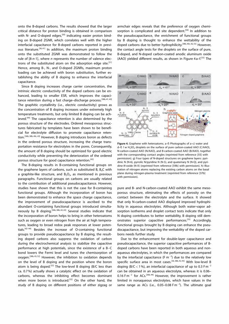
armchair edges reveals that the preference of oxygen chemi-sorption is complicated and site dependent.[54] In addition tothe pseudocapacitance, the enrichment of functional groupsby B doping is thought to enhance the wettability of thedoped carbons due to better hydrophilicity.[38b, 40c, 42, 55] However,the contact angle tests for the droplets on the surface of pure,B-doped, and N-doped carbon-coated anodic aluminum oxide(AAO) yielded different results, as shown in Figure 4 a–f.[55] The
pure and B- and N-carbon-coated AAO exhibit the same meso-porous structure, eliminating the effects of porosity on thecontact between the electrolyte and the surface. It showedthat only N-carbon-coated AAO displayed improved hydrophi-licity in aqueous electrolytes. Although both water-vapor ad-sorption isotherms and droplet contact tests indicate that onlyN doping contributes to better wettability, B doping still dem-onstrates superior capacitive performances.[55] Accordingly,functional groups brought by B doping can enhance the pseu-docapacitance, but improving the wettability of the doped car-bons needs further study.
Due to the enhancement for double-layer capacitance andpseudocapacitance, the superior capacitive performances of B-doped carbons have been reported in both aqueous and non-aqueous electrolytes, in which the performances are comparedby the interfacial capacitance (F m�2) due to the relatively lowspecific surface area in most cases.[36, 38b, 42, 43] With low-level Bdoping (B/C<1 %), an interfacial capacitance of up to 0.3 F m�2
can be obtained in an aqueous electrolyte, whereas it is 0.06–0.16 F m�2 for ACs.[36b, 44] However, the improvement is ratherlimited in nonaqueous electrolytes, which have values in thesame range as ACs (i.e. , 0.05–0.08 F m�2). The ultimate goal
Figure 4. Graphene with heteroatoms. a–f) Photographs of a–c) water andd–f) 1 m H2SO4 droplets on the surface of pure carbon-coated AAO (C/AAO),N-carbon-coated AAO (N/AAO), and B-carbon-coated AAO (B/AAO), togetherwith the corresponding contact angles (reprinted from reference [55] withpermission). g) Four types of N-doped structures on graphene layers : pyri-dinic N (N-6), pyrrolic N/pyridine N (N-5), and quaternary N (N-Q), and pyri-dine-N-oxide (N-X) (reprinted from reference [59b] with permission). h) Illus-tration of nitrogen atoms replacing the existing carbon atoms on the basalplane during nitrogen-plasma treatment (reprinted from reference [37b]with permission).

would be to develop B-doped graphene for EDLCs, combiningthe advantages introduced by B doping and the unique prop-erties of graphene. However, thus far the preparations of B-doped graphene are few, and the utilization for EDLCs has notbeen reported to the best of our knowledge.[56] Yet, the suc-cessful employment of B-doped graphene as the anode forlithium-ion batteries[57] makes B-doped graphene a promisingelectrode for EDLCs in the near future. In addition, since the Bdoping helps bring other atoms into the graphitic structureduring high-temperature treatment, the co-doping of boronand nitrogen or boron and phosphorus has also been demon-strated to exhibit positive effects on the capacitive per-formance.[40, 44, 45, 58] The substituted boron in graphitic struc-tures is preferentially bonded with nitrogen since the B�Nbond is in the most stable energy state.[44] The presence of B�N is proposed to provide pseudocapacitance through theredox reaction with the proton,[40d] and even with a sodiumion and lithium ion for neutral electrolytes,[40d, 45] which wasconfirmed by the larger current responses at lower potentials.On the other hand, the co-doping of boron and phosphoruswas shown to introduce more O-containing functional groupsto enhance the pseudocapacitance. The inhibition to hydrogenevolution at negative potentials and oxidation at highly posi-tive potentials were also observed for the co-doping of B andP to stabilize the capacitive performance within the potentialwindow.[40a, 58] The contributions of nitrogen and phosphoruswill be introduced in detail in the following sections.
4.2. Nitrogen doping
N doping is the most promising due to the well-establishedpreparation methods. It can be achieved through the ammoxi-dation of certain carbon materials[59] and direct carboniza-tion,[15a, 60] hydrothermal/solvothermal treatments,[61] or chemi-cal vapor deposition (CVD) treatments[37b, 62] of nitrogen-con-taining precursors. Four types of nitrogen-containing function-al groups have been found on graphene layers to enhance ca-pacitive performance: pyridinic N (N-6, 398.5 eV), pyrrolic N/pyridine N (N-5, 400 eV), quaternary N (N-Q, 410.2 eV), and pyr-idine-N-oxide (N-X, 403 eV).[37a, 63] As depicted in the left side ofFigure 4 g,[59b] N-6, N-5, and N-X structures are located on theedge of graphene, whereas N-Q appears either on the edge oron the basal plane of graphene. Since graphene layers are notalways perfect, disruption on the basal planes is commonly ob-served, leading to the formation of N-6 and N-5 on the defectsof the basal plane as well, as indicated by the right side of Fig-ure 4 h[37b] for the case of nitrogen-plasma treatment.
Similar to B doping, the incorporation of nitrogen changesthe surface electronic property of graphene and enhances thedouble-layer capacitance of the doped carbons. The DFT (den-sity functional theory) study for the proton adsorption on thedoped edges indicates that proton exhibits stronger interac-tions with N-doped edges rather than B- or O-doped edges,[50]
which may be ascribed to the increased basicity introduced byN-containing functional groups on the surface.[46, 64] Differentfrom the case for O-containing functional groups, which bearmore acidic groups (e.g. , carboxylic groups and lactones)[65]
than basic and neutral groups (e.g. , phenols, ethers, and car-bonyls) to render acidic surface nature on carbons, the pres-ence of N-containing functional groups introduces more basici-ty, especially for the ones containing high amounts of N-6 andN-5 due to their electron donor characteristics.[37a, 63b] On theother hand, the DFT study also reveals that the type and theposition (i.e. , edge or basal planes) of N-containing functionalgroups influence the ion adsorption on the surface, showingthat N-6 on the basal plane and anion N-5 on both basal andedge planes result in the larger binding energies for potassiumions on the electrode surface, which facilitates the formationof a double layer.[37b]
The electric conductivity of carbons can also be tuned by Ndoping. The presence of N-Q and N-X has been reported to en-hance the electron transport through the carbon materials,maintaining superior capacitance retention during the fastcharge–discharge process.[37a, 63b] N-Q is proposed to lower theenergy gap between the highest occupied molecular orbital(HOMO) and lowest unoccupied molecular orbital (LUMO),leading to improved electron transfer ability.[66] Such a phenom-enon was confirmed by the high correlation coefficient(>0.97) between the specific capacitance and the amounts ofN-Q and N-X when measured at high current loads.[37a, 63b] How-ever, the enhancement of electric conductivity is limited by theconcentration of N doping. When the amount of nitrogen ex-ceeds 12 at %, the electric conductivity starts decreasing dueto the interruption of graphitic structure by N doping.[67]
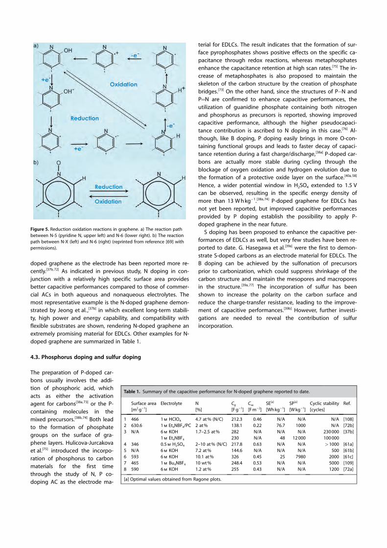
In addition to the effects on double-layer capacitance andcapacitance retention, the contribution of pseudocapacitanceis the most important feature for N doping, as indicated ina previous study.[40c] N-6 and N-5 are believed to provide pseu-docapacitance through redox reactions involving pro-tons.[37b, 66, 68] The presence of N-6 and N-5 along with quinonefunctional groups on the doped carbons has shown significanteffects on capacitive performance, which was proven by thehigh correlation coefficient (>0.99) between specific capaci-tance and the amounts of N-6, N-5, and quinone groups.[37a] Arecent study has explored the detailed mechanisms regardingthe redox reactions of nitrogen-containing functional groupsthrough ex situ coupled XPS and CV study.[69] Two electro-chemical redox reactions are proposed: 1) the redox reactionbetween N-5 (only pyridone-N) and N-6 and 2) the redox reac-tion between N-X and N-6. The reaction paths are shown inFigure 5 a, b.[69] Since proton is involved in redox reactions forN-containing functional groups, the pseudocapacitance can beobserved at less positive potentials when measured in acidicelectrolytes.[64b] Although the alkaline solution lacks a proton,significant pseudocapacitance can still be achieved, probablydue to the redox reactions involving ions such as potassiumion.[70] Compared with O-containing functional groups, thepseudocapacitance brought by N-containing functional groupsis more stable, and less capacitance decay is obtained after cy-cling.[64a, 71] However, N-containing functional groups showalmost no benefits for pseudocapacitance in neutral electro-lytes and nonaqueous electrolytes.[60b, 70]
Although N doping on various forms of carbon materials hasbeen widely investigated for EDLCs, the employment of N-
doped graphene as the electrode has been reported more re-cently.[37b, 72] As indicated in previous study, N doping in con-junction with a relatively high specific surface area providesbetter capacitive performances compared to those of commer-cial ACs in both aqueous and nonaqueous electrolytes. Themost representative example is the N-doped graphene demon-strated by Jeong et al. ,[37b] in which excellent long-term stabili-ty, high power and energy capability, and compatibility withflexible substrates are shown, rendering N-doped graphene anextremely promising material for EDLCs. Other examples for N-doped graphene are summarized in Table 1.
4.3. Phosphorus doping and sulfur doping
terial for EDLCs. The result indicates that the formation of sur-face pyrophosphates shows positive effects on the specific ca-pacitance through redox reactions, whereas metaphosphatesenhance the capacitance retention at high scan rates.[75] The in-crease of metaphosphates is also proposed to maintain theskeleton of the carbon structure by the creation of phosphatebridges.[73] On the other hand, since the structures of P�N andP=N are confirmed to enhance capacitive performances, theutilization of guanidine phosphate containing both nitrogenand phosphorus as precursors is reported, showing improvedcapacitive performance, although the higher pseudocapaci-tance contribution is ascribed to N doping in this case.[76] Al-though, like B doping, P doping easily brings in more O-con-taining functional groups and leads to faster decay of capaci-tance retention during a fast charge/discharge,[38a] P-doped car-bons are actually more stable during cycling through theblockage of oxygen oxidation and hydrogen evolution due tothe formation of a protective oxide layer on the surface.[40a, 58]
Hence, a wider potential window in H2SO4 extended to 1.5 Vcan be observed, resulting in the specific energy density ofmore than 13 W h kg�1.[38a, 74] P-doped graphene for EDLCs hasnot yet been reported, but improved capacitive performancesprovided by P doping establish the possibility to apply P-doped graphene in the near future.
S doping has been proposed to enhance the capacitive per-formances of EDLCs as well, but very few studies have been re-ported to date. G. Hasegawa et al.[39a] were the first to demon-strate S-doped carbons as an electrode material for EDLCs. TheB doping can be achieved by the sulfonation of precursorsprior to carbonization, which could suppress shrinkage of thecarbon structure and maintain the mesopores and macroporesin the structure.[39a, 77] The incorporation of sulfur has beenshown to increase the polarity on the carbon surface andreduce the charge-transfer resistance, leading to the improve-ment of capacitive performances.[39b] However, further investi-gations are needed to reveal the contribution of sulfurincorporation.
Table 1. Summary of the capacitive performance for N-doped graphene reported to date.
Surface area[m2 g�1]
Electrolyte N[%]
Cg
[F g�1]Csa
[F m�2]SE[a]
[Wh kg�1]SP[a]
[W kg�1]Cyclic stability[cycles]
Ref.
1 466 1 m HClO4 4.7 at % (N/C) 212.3 0.46 N/A N/A N/A [108]2 630.6 1 m Et4NBF4/PC 2 at % 138.1 0.22 76.7 1000 N/A [72b]3 N/A 6 m KOH 1.7–2.5 at % 282 N/A N/A N/A 230 000 [37b]
1 m Et4NBF4 230 N/A 48 12 000 100 0004 346 0.5 m H2SO4 2–10 at % (N/C) 217.8 0.63 N/A N/A >1000 [61a]5 N/A 6 m KOH 7.2 at % 144.6 N/A N/A N/A 500 [61b]6 593 6 m KOH 10.1 at % 326 0.45 25 7980 2000 [61c]7 465 1 m Bu4NBF4 10 wt % 248.4 0.53 N/A N/A 5000 [109]8 590 6 m KOH 1.2 at % 255 0.43 N/A N/A 1200 [72a]
[a] Optimal values obtained from Ragone plots.
Figure 5. Reduction oxidation reactions in graphene. a) The reaction pathbetween N-5 (pyridine N, upper left) and N-6 (lower right). b) The reactionpath between N-X (left) and N-6 (right) (reprinted from reference [69] withpermissions).
The preparation of P-doped car-bons usually involves the addi-tion of phosphoric acid, which acts as either the activation agent for carbons[38a, 73] or the P-containing molecules in the mixed precursors.[38b, 74] Both lead to the formation of phosphate groups on the surface of gra-phene layers. Hulicova-Jurcakova et al.[75] introduced the incorpo-ration of phosphorus to carbon materials for the first time through the study of N, P co-doping AC as the electrode ma-

5. Electrode Materials Based on Graphene/Metal Oxide Composites
Due to abundant defects and chemical moieties createdduring synthesis, the exceptional properties of graphene aregreatly diminished. The intrinsic specific surface area of gra-phene composites is greatly reduced by aggregation andstacking between individual graphene sheets driven by thestrong p–p interactions. In addition, as the intersheet contactresistance increases, the conductivity of graphene decreases.Previous studies on the capacitive behavior of graphene elec-trode materials indicate that the actual capacitive performanceis much lower than the anticipated value estimated from theultrahigh theoretical surface area because of the serious aggre-gation and restacking of graphene sheets resulting fromstrong van der Waals interactions between individual graphenesheets.[78] This phenomenon is the most serious issue whenconsidering graphene for applications in various fields. There-fore, how to significantly inhibit the restacking and effectivelyexpose the surface area of graphene sheets becomes an im-portant topic in developing graphene-sheet-based electrodematerials. Most researchers introduce extra additives duringthe preparation process, which may be a pure additive or anintrinsically active material for their applications. Accordingly,various graphene-based composites, including metal oxidenanoparticles/graphene sheet[79] and carbon nanomaterials/graphene sheet,[30] were demonstrated to solve the above re-stacking issue.
These hierarchical architectures of graphene-sheet-basedcomposites (Figure 6 a), including 1) superiorly conductive gra-phene sheets, 2) extra additives, and 3) macro-/mesospace,show some predominance as electrode materials. Here theextra additive, dispersed on the surface of graphene sheets,can act as a nanospacer to prevent the restacking of graphenesheets during the reduction of GO. On the other hand, superi-orly conductive graphene with a length generally longer than5 mm, which depends on the size of the graphene sheet, willprovide a 2D smooth electronic superhighway for rapid chargestorage and delivery. In addition, the high surface area gra-phene sheet also allows the uniform dispersion of extra addi-tives to promote the utilization of electrode materials. Finally,the macro-/mesospace, constructed between the graphenesheet and nanoparticle, also facilitates the transport of electro-lytes or reactants. Therefore, reservoirs for electrolytes or reac-tants can be formed within macro-/mesopores for facile trans-port of electrolytes or reactants in the short nanochannels. Inaddition, I. Honma et al. proposed that the space between gra-phene sheets and nanocrystallites can also be used as a flexiblespace for crystal expansion during the insertion of Li ions, sig-nificantly improving the poor cycle life of metal oxides.[80]
Therefore, this design of hierarchical graphene-sheet-basedcomposites considers not only issues of electrode materials,such as electron/electrolyte transport, utilization of electroac-tive species, and cycle life, but also the restacking of graphenesheets. Accordingly, novel graphene-sheet-based compositesare very promising for next-generation high-performance elec-trode materials.
L. Pan et al. reported graphene–ZnO and graphene–SnO2
composites for supercapacitor applications.[81] Graphene–ZnOcomposites exhibit a higher capacitance of 61 F g�1 with anenergy density of 4.8 W h kg�1, which was higher than that ofgraphene–SnO2 samples. The results showed that the gra-phene–ZnO composite exhibited an improved electrochemicalcapacitance over that of pristine ZnO or pure graphene, withgood reversible charge–discharge behavior.[81, 82] In another arti-cle, Z. Fan et al. reported graphene/MnO2 composites for su-percapacitor applications.[83] The graphene/MnO2 composite (at78 wt % MnO2) shows a specific capacitance of 310 F g�1 at2 mV s�1. Thus, the hybridization of MnO2 and graphene causesan increase in conductivity and specific surface area of thecomposites, ultimately leading to high rate performance.[83, 84]
Furthermore, our group proposed a novel two-step strategy towell-dispersed single-phase unitary and binary oxide nanocrys-tals (e.g. , RuO2, SnO2, TiO2, Mn3O4, NiCo2O4, and Zn2SnO4) ontographene nanosheets for novel applications, including energystorage/conversion systems and sensors.[85] S. Ramaprabhuet al. also reported on graphene decoration with differentmetal oxides (such as RuO2, TiO2, and Fe3O4) as well as polyani-line by a chemical route.[86] The cyclic voltammetric studies atvarious sweep rates in 1 m H2SO4 show that RuO2/graphenecomposites possess a higher specific capacitance of 220 F g�1
at 10 A g�1 than composites with other metal oxides, such asTiO2 and Fe3O4. This is attributable to the better electrical con-
Figure 6. Graphene materials using spacers. a) A schematic illustration of hi-erarchical graphene-sheet-based composites, including superiorly conduc-tive graphene sheets, nanospacers, and macro-/mesospaces. The nanospacercan be any metallic nanoparticle, oxide nanocrystallite, conductive polymer,or carbon nanomaterial. b) Schematic for the preparation of graphene/SnO2-MWCNT composites (reproduced from reference [88] with permission).

ductivity and reversible Faradic reactions of RuO2 than those ofother metal oxides. Similar results were obtained in anotherwork by H. N. Alshareef et al. ,[87] in which they reported variousmetal oxide composites (such as SnO2, MnO2, and RuO2) withgraphene nanosheets. Moreover, RuO2/graphene (365 F g�1)showed a higher specific capacitance than SnO2/graphene(195 F g�1). Furthermore, H. N. Alshareef et al.[88] reported ongraphene nanosheet/SnO2-MWCNT composites for supercapa-citor applications (Figure 6 b). The advantage of this structureis the significant inhibition of restacking and effective exposureof the surface area for graphene sheets. These nanocompositesachieved a high specific capacitance of 224 F g�1, with anenergy and power density of 31 W h kg�1 and 17 kW kg�1, re-spectively. The symmetric supercapacitor device fabricatedusing these nanocomposites shows 81 % retention after 6000cycles.
Q. Yan et al.[89] reported on a supercapacitor consisting ofa Fe3O4/reduced graphene oxide (RGO) composite, whichshowed a specific capacitance of 480 F g�1 at a discharge cur-rent density of 5 A g�1; the corresponding energy and powerdensities were 67 W h kg�1 and 5.5 kW kg�1, respectively. C. M.Li et al. reported on CeO2–graphene nanosheet composites,which show an improved specific capacitance of 208 F g�1. Thisis due to a synergy effect contributing to the improved elec-tronic conductivity of CeO2 as well as to the better utilizationof graphene.[90] Layered double hydroxides (LDHs, especiallyCo–Al) and graphene composites are a point of interest insome studies.[79, 91] The studies show that the formation ofLDHs prevents the restacking of graphene nanosheets; mean-while, the formation of complex structures depends on theconcentration of LDH ions. Furthermore, these studies revealthe advantages of these composites as a high specific surfacearea, more utilization of LDH structures, better conductivity,etc. These electrodes show a high specific capacitance of1200 F g�1 at a scan rate of 5 mV s�1.[79] Our group[92] reportedthe microwave-assisted hydrothermal synthesis of Mn3O4/gra-phene composites for supercapacitor application. The aqueousasymmetric supercapacitor shows capacitor behavior witha cell voltage of up to 2 V, as shown in Figure 7 a–d. Theseelectrodes in the asymmetric configuration with nitrogen-doped graphene show energy and power densities of11 W h kg�1 and 24 kW kg�1, respectively, at a current density of24 A g�1. This and some other results suggest that a graphenenanosheet could be used as an ideal conductive matrix for en-hancing the capacitance performance of Mn3O4.[92, 93]
P. Chen et al.[94] reported on the development of 3D porousgraphene/cobalt oxide electrodes for a high-performance su-percapacitor. These electrodes show high specific capacitanceof 1100 F g�1 at a current density of 10 A g�1. T. Yu et al.[95] re-ported on the development of Co3O4/graphene composites forsupercapacitor applications, which show a specific capacitanceof 159 F g�1 at a scan rate of 5 mV s�1. In addition, cobaltoxide/graphene composites have been considered as one ofthe most promising materials for next-generation supercapaci-tors because of their advantages such as cost-effectiveness, en-vironmental friendliness, and high specific capacitance.[96] X. S.Zhao et al.[97] reported on the development of a 3D nanostruc-
ture of nickel hydroxide/graphene composites for supercapaci-tor applications, in which nickel hydroxide embedded in a CNTacts as a pillar for graphene sheets. The supercapacitor studyfor this 3D nanostructure showed a high specific capacitanceof 1235 F g�1 at 1 A g�1, but the capacitance decreased to780 F g�1 with an increase in current density (up to 20 A g�1).The mass ratio of nickel to graphene, morphology, and micro-structure were important to the performances of such nano-composites.[98]
6. Electrode Materials Based on Graphene/Electrically Conducting Polymer Composites
Graphene/polymer composites have attracted great attentionbecause of their high strength and improved conductivity. Gra-phene materials are often mixed with polymers to form com-posites, especially when fabricating flexible devices. There areseveral previous reports on the development of graphene/polymer composites as electrodes for different applicationssuch as active layers of organic solar cells, counter electrodesof dye-sensitized solar cells, transparent conducting electrodes,catalytic electrodes, and polymer electrolyte membranes offuel cells.[99] H. M. Cheng et al.[100a] reported on graphene/poly-aniline composites by in situ anodic polymerization for flexiblesupercapacitors. These composites show a very good capaci-tance of 233 F g�1 at a scan rate of 2 mV s�1 and stability up to1500 cycles. J. Xu et al.[100b] have reported the growth of poly-aniline nanorod arrays on graphene sheets for supercapacitorapplications (Figure 8 a, b). These electrodes show a specific ca-pacitance of 555 F g�1 at a current density of 0.2 A g�1 in 1 m
H2SO4 solution and stability up to 2000 cycles. Recently, ourgroup reported the development of layered graphene andpolyaniline composites (TEM and SEM images are shown in
Figure 7. GO composites for supercapacitors. a) Cyclic voltammograms of (1)graphene-modified Mn3O4 and (2) N-doped RGO at 10 mV s�1. b, c) The con-stant-current CD profiles of an asymmetric supercapacitor consisting of a gra-phene-modified Mn3O4 cathode and an N-doped RGO anode b) with the cellvoltage of (1) 1.6, (2) 1.8, and (3) 2.0 V at 1.2 A g�1 and c) with a cell voltageof 2.0 V at 1.2, 2.4, 6, 12, and 24 A g�1. d) The Ragone plot for this asymmet-ric supercapacitor (reproduced from reference [92] with permission).

Figure 8 c, d) for which we have obtained highest specific ca-pacitance of 286 F g�1 at a scan rate of 5 mV s�1.[23] G. Shiet al.[101] reported a flexible supercapacitor based on flexiblegraphene and polyaniline nanofibers, which is shown in Fig-ure 8 e, f. The conductivity of polyaniline fibers was found to beincreased up to 44 % when the composite was made with gra-phene. This flexible supercapacitor shows a specific capaci-tance of 210 F g�1 at a current density of 0.3 A g�1. Many othersreports involving graphene/polymer composites for supercapa-citor applications are listed in Table 2.
As mentioned above, the p–p stacking between graphenesheets usually causes much lower real specific surface areathan their theoretical values. In many cases, mixing with poly-mer increases the severity of this problem. There is need fordevelopment of new techniques for homogeneous mixing ofsingle layered graphene sheets into polymer matrix. The con-struction of graphene-based 3D architectures in the compositeform can overcome this problem.
7. Asymmetric Supercapacitors Based onGraphene Materials
The fabrication of asymmetric supercapacitors using aqueouselectrolytes is an efficient way to improve the energy densityof supercapacitors. The key to fabricating an asymmetric su-percapacitor is to choose electrode materials with complemen-tary working potential windows in the same electrolyte. Incase of aqueous electrolyte, the main limitation is that the op-
erating potential window cannot extended beyond their ther-modynamic limit (1.23 V). However, by use of asymmetric su-percapacitor configuration, we can easily bypass this problemby extending their operating potential window up to 2 V,which results in high-energy density supercapacitors.[102] Formetal oxides and polymers, a limited potential window isa problem for the improvement of energy density; on theother hand, the small capacitance value of carbon material isalso a limitation. The asymmetric configuration, however, couldsolve these problems.
Our group[103] reported on the development of an asymmet-ric cell consisting of a positive electrode of polyaniline nanofib-ers and a negative electrode of graphene nanosheets. Theenergy and power densities of this asymmetric supercapacitorconsisting of PANI and graphene reach approximately4.86 W h kg�1 and 8.75 kW kg�1, respectively, at 500 mV s�1,which is promising in the application of next-generation super-capacitors. X. S. Zhao et al.[104] reported on the development ofasymmetric supercapacitors based on graphene-modifiedruthenium oxide (17 % Ru) and graphene. The results showedan energy density of 26 W h kg�1 at a power density of49 kW kg�1 for the configuration, which is more than doublethe symmetric configuration. The Ragone plots of symmetricand asymmetric supercapacitors based on RGO, RGO–RuO2,and RGO–PANI are shown in Figure 9 d. S. G. Lee et al.[105] re-ported a solid-state flexible asymmetric supercapacitor basedon ionic-liquid-functionalized graphene and RuO2. The compa-rative cyclic voltammograms (CVs) for both electrodes ata scan rate of 50 mV s�1 (Figure 9 a) and the asymmetric super-capacitor at different potential windows (Figure 9 b) areshown. The galvanostatic charge–discharge curves for symmet-
Figure 8. GO and conducting polymer composites. a) Schematic illustrationof the nucleation and growth mechanism of PANI nanowires. b, c) SEMimages of graphene oxide–polyaniline nanowire arrays (reproduced from ref-erence [100b] with permission). d) TEM image of graphene oxide–polyanilinecomposites. The inset shows a SEAD pattern for the composites (reproducedfrom reference [23] with permission). e) Digital photograph of graphene–polyaniline nanofiber composite film. f) Cross-sectional SEM image of gra-phene–polyaniline nanofiber (reproduced from reference [101] with permis-sion).
Figure 9. Asymmetric supercapacitors based on GO. a) Comparative CVcurves obtained for chemically modified graphene and RuO2 chemicallymodified graphene films in aqueous 1 m H2SO4 solution at a scan rate of50 mV s�1 (reproduced from reference [105] with permission). b) CV curvesobtained from asymmetric SC devices with different cell voltages of 1, 1.2,1.4, 1.6, and 1.8 V at a scan rate of 50 mV s�1 (reproduced from reference[105] with permission). c) Galvanostatic charge–discharge studies of sym-metric and asymmetric supercapacitor. d) Ragone plots of symmetric andasymmetric supercapacitors based on RGO, RGO–RuO2, and RGO–PANI (re-produced from reference [104] with permission).

ric and asymmetric supercapacitor are shown in Figure 9 c. Thisasymmetric supercapacitor shows energy and power densitiesof 19.7 W h kg�1 and 0.5 kW kg�1, respectively, for a current den-sity of 0.5 A g�1. An asymmetric supercapacitor based on gra-phene hydrogel and MnO2 nanoflakes on nickel foam was re-ported by H. Duan et al.[106] This asymmetric supercapacitorcan be cycled reversibly in a wide voltage window from 0 to2 V and exhibits an energy density of 23 W h kg�1 with a powerdensity of 1.0 kW kg�1. Thus, graphene has been shown to bean important material in the asymmetric combination whenwidening the cell voltage to 2 V for metal oxides and alsouseful for future solid-state devices based on a polymer gelelectrolyte.[107]
8. Summary and Outlook
Graphene is a very attractive electrode material for energystorage. We can find many advantages, such as high specificsurface area, an interconnected porous structure, a controlledpore size that matches electrolyte ions, good wettability
toward the electrolyte, and high electrical conductivi-ty. Although pristine graphene has a significantlylower capacitance value than we expected, improvedenergy storage performance can be achieved bycombining double-layer capacitance together withfast and highly reversible pseudocapacitance. For ex-ample, the synthesis of graphene-based composites,the use of ionic liquids with an electrochemicallystable window of 4 V, and the fabrication of asym-metric configurations (e.g. , a positive electrode ofMn3O4/graphene composites and a negative elec-trode of N-doped graphene sheets) can maximize theworking potential range for each electrode, resultingin a wide potential window. A higher cell voltage im-proves both energy and power densities, as it is pro-portional to the voltage window (V2). The safe opera-tion with ‘green chemistry’ is a promising electro-chemical system for the next generation of superca-pacitor applications. For the next generation of gra-phene-based supercapacitors, it is expected thatenergy, power, and reliability, which are required formodern technology, will increase. In the future, thechallenging issue in supercapacitor fields will be thedevelopment of highly efficient materials throughcost-effective methods in order to realize their excel-lent performance, which is not attainable by otherenergy storage devices. Thus, future research shouldbe directed toward the development of electrodematerials with a high charge capacity and minimumESR.
Keywords: carbon · energy storage · graphene ·nanostructures · porous materials
[1] a) H. Jiang, P. S. Lee, C. Z. Li, Energy Environ. Sci. 2013, 6,41 – 53; b) J. Zhang, X. S. Zhao, ChemSusChem 2012, 5,818 – 841; c) S. Bose, T. Kuila, A. K. Mishra, R. Rajasekar, N. H.Kim, J. H. Lee, J. Mater. Chem. 2012, 22, 767 – 784; d) M.
Winter, R. J. Brodd, Chem. Rev. 2004, 104, 4245 – 4269; e) A. Burke, J.Power Sources 2000, 91, 37 – 50.
Table 2. The electrode material, electrolytes and electrochemical parameters used fordifferent graphene–polymer nanocomposites.[a]
Electrodematerials
Electrolyte([mol L�1])
C[F g�1]
Currentdensity
Scan rate[mV s�1]
Cycles Ref.
Ppy-decorated G NaNO3 (1) 294 10 mA cm�2 – – [110]P–PANI–G HClO4 (1) 878 1 A g�1 – 1000 [111]CFGO–PANI H2SO4 (1) 525 0.3 A g�1 – 200 [112]G–Ppy nanotubes H2SO4 (2) 400 0.3 A g�1 – 200 [113]Ppy–GNP Na2SO4 (0.5) 285 0.5 A g�1 – 1000 [114]G–PANI H2SO4 (2) 526 0.2 A g�1 – – [115]PANI–RGO H2SO4 (1) 250 – 10 – [116]G–Ppy H2SO4 (2) 417 – 10 500 [117]G–Ppy LiClO4 (0.1) 1510 – 10 – [118]GO–PANI H2SO4 (1) 489 400 mA g�1 – 500 [119]G–PANI H2SO4 (1) 1126 – 1 1000 [120]GNS–Ppy NaCl (1) 165 1 A g�1 – 1000 [121]GO–PANI H2SO4 (1) 746 200 mA g�1 – 500 [122]PNW–GOS H2SO4 (1) 555 0.2 A g�1 – 2000 [100b]G–PANI H2SO4 (2) 480 0.1 A g�1 – 1000 [123]PpPD–G H2SO4 (1) 248 2 A g�1 – 1000 [124]GNS–PANI H2SO4 (1) 375 0.5 A g�1 – 500 [7b]G–Ppy H2SO4 (1) 335 1 A g�1 – 1000 [125]G–Ppy H2SO4 (1) 420 0.5 A g�1 – 200 [126]G–PANI Et4N+ ·BF4
�/PC (1) 250 0.5 A g�1 – 1000 [127]G–PANI H2SO4 (1) 346 4 A g�1 – 600 [128]G–CP H2SO4 (1) 201 – 10 100 [129]RGO–PANI H2SO4 (0.5) 970 2.5 A g�1 – 1700 [130]GO–Ppy KCl (0.1) 356 0.5 A g�1 – 1000 [131]G–PEDOT H2SO4 (2) 342 20 mA cm�2 – – [132]GNS–PANI H2SO4 (1) 1130 – 5 1000 [133]G–Ppy KCl (1) 237 – 100 – [134]G–Ppy H2SO4 (1) 318 – 2 1000 [135]G–PANI H2SO4 (1) 640 0.1 A g�1 – 1000 [136]GO–Ppy H2SO4 (1) 510 0.3 A g�1 – 1000 [137]G-doped PANI H2SO4 (1) 531 200 mA g�1 – – [138]G–PANI H2SO4 (1) 233 – 2 1500 [100a]G–PANI H2SO4 (1) 210 0.3 A g�1 – 800 [101]
[a] Ppy: polypyrrole; G: graphene; PANI: polyaniline; CFGO: carboxyl-functionalizedgraphene oxide; GNP: graphene nanoplatelates; PNW: polyanilyne nanowires; GOS:graphene oxide sheets; PC: propylene carbonate; CP: poly(3,4-propylenedioxythio-phene); PEDOT: polyethylenedioxythiophene.
[2] P. Simon, Y. Gogotsi, Nat. Mater. 2008, 7, 845 – 854.[3] B. E. Conway, Electrochemical Supercapacitors : Scientific Fundamentals
and Technological Applications, Kluwer Academic/Plenum Publisher, New York, 1999.
[4] a) N. L. Torad, M. Hu, Y. Kamachi, K. Takai, M. Imura, M. Naito, Y. Yamau-chi, Chem. Commun. 2013, 49, 2521 – 2523; b) M. Hu, J. Reboul, S. Furu-kawa, N. L. Torad, Q. Ji, P. Srinivasu, K. Ariga, S. Kitagawa, Y. Yamauchi,J. Am. Chem. Soc. 2012, 134, 2864 – 2867; c) W. Chaikittisilp, K. Ariga, Y. Yamauchi, J. Mater. Chem. A 2013, 1, 14; d) L. Radhakrishnan, J. Reboul, S. Furukawa, P. Srinivasu, S. Kitagawa, Y. Yamauchi, Chem. Mater. 2011, 23, 1225 – 1231.
[5] a) W. Chaikittisilp, M. Hu, H. Wang, H. S. Huang, T. Fujita, K. C. Wu, L. C. Chen, Y. Yamauchi, K. Ariga, Chem. Commun. 2012, 48, 7259 – 7261;b) N. L. Torad, R. R. Salunkhe, Y. Li, H. Hamoudi, M. Imura, Y. Sakka, C. C. Hu, Y. Yamauchi, Chem. Eur. J. 2014, 20, 7895 – 7900.
[6] a) C. C. Hu, J. Y. Lin, Electrochim. Acta 2002, 47, 4055 – 4067; b) C. C. Hu,X. X. Lin, J. Electrochem. Soc. 2002, 149, A1049 – A1057.
[7] a) H. Y. Hsu, K. H. Chang, R. R. Salunkhe, C. T. Hsu, C. C. Hu, Electrochim. Acta 2013, 94, 104 – 112; b) R. R. Salunkhe, K. Jang, S. W. Lee, H. Ahn, RSC Adv. 2012, 2, 3190 – 3193; c) R. R. Salunkhe, K. Jang, H. Yu, S. Yu, T. Ganesh, S. H. Han, H. Ahn, J. Alloys Compd. 2011, 509, 6677 – 6682.

[8] a) D. S. Dhawale, D. P. Dubal, V. S. Jamadade, R. R. Salunkhe, C. D. Lo-khande, Synth. Met. 2010, 160, 519 – 522; b) C. C. Hu, C. H. Chu, Mater.Chem. Phys. 2000, 65, 329 – 338.
[9] a) K. H. Chang, C. C. Hu, Appl. Phys. Lett. 2006, 88, 193102; b) C. C. Hu,K. H. Chang, M. C. Lin, Y. T. Wu, Nano Lett. 2006, 6, 2690 – 2695; c) K. M.Lin, K. H. Chang, C. C. Hu, Y. Y. Li, Electrochim. Acta 2009, 54, 4574 –4581; d) W. Sugimoto, S. Makino, R. Mukai, Y. Tatsumi, K. Fukuda, Y.Takasu, Y. Yamauchi, J. Power Sources 2012, 204, 244 – 248; e) S.Makino, Y. Yamauchi, W. Sugimoto, J. Power Sources 2013, 227, 153 –160; f) H. S. Huang, K. H. Chang, N. Suzuki, Y. Yamauchi, C. C. Hu, K. C.Wu, Small 2013, 9, 2520 – 2526; g) B. P. Bastakoti, H. Oveisi, C. C. Hu,K. C. W. Wu, N. Suzuki, K. Takai, Y. Kamachi, M. Imura, Y. Yamauchi, Eur.J. Inorg. Chem. 2013, 1109 – 1112; h) M. Hu, S. Ishihara, Y. Yamauchi,Angew. Chem. 2013, 125, 1273 – 1277; Angew. Chem. Int. Ed. 2013, 52,1235 – 1239; i) B. P. Bastakoti, R. R. Salunkhe, J. Ye, Y. Yamauchi, Phys.Chem. Chem. Phys. 2014, 16, 10425 – 10428.
[10] a) B. P. Bastakoti, H. S. Huang, L. C. Chen, K. C. Wu, Y. Yamauchi, Chem.Commun. 2012, 48, 9150 – 9152; b) B. P. Bastakoti, Y. Kamachi, H. S.Huang, L. C. Chen, K. C. W. Wu, Y. Yamauchi, Eur. J. Inorg. Chem. 2013,39 – 43; c) R. R. Salunkhe, B. P. Bastakoti, C. T. Hsu, N. Suzuki, J. H. Kim,S. X. Dou, C. C. Hu, Y. Yamauchi, Chem. Eur. J. 2014, 20, 3084 – 3088.
[11] a) G. X. Zhao, T. Wen, C. L. Chen, X. K. Wang, RSC Adv. 2012, 2, 9286 –9303; b) B. Luo, S. Liu, L. Zhi, Small 2012, 8, 630 – 646; c) Y. Huang, J.Liang, Y. Chen, Small 2012, 8, 1805 – 1834; d) H. J. Choi, S. M. Jung,J. M. Seo, D. W. Chang, L. Dai, J. B. Baek, Nano Energy 2012, 1, 534 –551.
[12] a) A. K. Geim, K. S. Novoselov, Nat. Mater. 2007, 6, 183 – 191; b) C. N.Rao, A. K. Sood, K. S. Subrahmanyam, A. Govindaraj, Angew. Chem.2009, 121, 7890 – 7916; Angew. Chem. Int. Ed. 2009, 48, 7752 – 7777.
[13] D. A. Brownson, D. K. Kampouris, C. E. Banks, Chem. Soc. Rev. 2012, 41,6944 – 6976.
[14] D. R. Dreyer, S. Park, C. W. Bielawski, R. S. Ruoff, Chem. Soc. Rev. 2010,39, 228 – 240.
[15] a) L. L. Zhang, R. Zhou, X. S. Zhao, J. Mater. Chem. 2010, 20, 5983 –5992.
[16] M. D. Stoller, S. J. Park, Y. W. Zhu, J. H. An, R. S. Ruoff, Nano Lett. 2008,8, 3498 – 3502.
[17] S. R. C. Vivekchand, C. S. Rout, K. S. Subrahmanyam, A. Govindaraj,C. N. R. Rao, J. Chem. Sci. 2008, 120, 9 – 13.
[18] Q. Du, M. Zheng, L. Zhang, Y. Wang, J. Chen, L. Xue, W. Dai, G. Ji, J.Cao, Electrochim. Acta 2010, 55, 3897 – 3903.
[19] S. H. Lee, H. W. Kim, J. O. Hwang, W. J. Lee, J. Kwon, C. W. Bielawski,R. S. Ruoff, S. O. Kim, Angew. Chem. 2010, 122, 10282 – 10286; Angew.Chem. Int. Ed. 2010, 49, 10084 – 10088.
[20] C. Liu, Z. Yu, D. Neff, A. Zhamu, B. Z. Jang, Nano Lett. 2010, 10, 4863 –4868.
[21] X. Cao, Y. Shi, W. Shi, G. Lu, X. Huang, Q. Yan, Q. Zhang, H. Zhang,Small 2011, 7, 3163 – 3168.
[22] Z. Xu, Z. Li, C. M. B. Holt, X. Tan, H. Wang, B. S. Amirkhiz, T. Stephenson,D. Mitlin, J. Phys. Chem. Lett. 2012, 3, 2928 – 2933.
[23] R. R. Salunkhe, S. H. Hsu, K. C. Wu, Y. Yamauchi, ChemSusChem 2014, 7,1551 – 1556.
[24] K. S. Kim, S. J. Park, Electrochim. Acta 2011, 56, 1629 – 1635.[25] G. Ning, Z. Fan, G. Wang, J. Gao, W. Qian, F. Wei, Chem. Commun.
2011, 47, 5976 – 5978.[26] Y. X. Xu, K. X. Sheng, C. Li, G. Q. Shi, ACS Nano 2010, 4, 4324 – 4330.[27] M. M. Hantel, T. Kaspar, R. Nesper, A. Wokaun, R. Kçtz, Electrochem.
Commun. 2011, 13, 90 – 92.[28] Z. B. Lei, N. Christov, X. S. Zhao, Energy Environ. Sci. 2011, 4, 1866 –
1873.[29] Y. S. Wang, S. Y. Yang, S. M. Li, H. W. Tien, S. T. Hsiao, W. H. Liao, C. H.
Liu, K. H. Chang, C. C. M. Ma, C. C. Hu, Electrochim. Acta 2013, 87, 261 –269.
[30] Y. Wang, Y. Wu, Y. Huang, F. Zhang, X. Yang, Y. Ma, Y. Chen, J. Phys.Chem. C 2011, 115, 23192 – 23197.
[31] S. Y. Yang, K. H. Chang, Y. F. Lee, C. C. M. Ma, C. C. Hu, Electrochem.Commun. 2010, 12, 1206 – 1209.
[32] J. J. Yoo, K. Balakrishnan, J. Huang, V. Meunier, B. G. Sumpter, A. Srivas-tava, M. Conway, A. L. Reddy, J. Yu, R. Vajtai, P. M. Ajayan, Nano Lett.2011, 11, 1423 – 1427.
[33] F. C. Wu, R. L. Tseng, C. C. Hu, C. C. Wang, J. Power Sources 2006, 159, 1532 – 1542.
[34] Y. Li, M. van Zijll, S. Chiang, N. Pan, J. Power Sources 2011, 196, 6003 –6006.
[35] Y. Zhu, S. Murali, M. D. Stoller, K. J. Ganesh, W. Cai, P. J. Ferreira, A. Pirkle, R. M. Wallace, K. A. Cychosz, M. Thommes, D. Su, E. A. Stach, R. S. Ruoff, Science 2011, 332, 1537 – 1541.
[36] a) S. Shiraishi, M. Kibe, T. Yokoyama, H. Kurihara, N. Patel, A. Oya, Y. Ka-buragi, Y. Hishiyama, Appl. Phys. A 2006, 82, 585 – 591; b) D. W. Wang,F. Li, Z. G. Chen, G. Q. Lu, H. M. Cheng, Chem. Mater. 2008, 20, 7195 –7200.
[37] a) D. Hulicova-Jurcakova, M. Seredych, G. Q. Lu, T. J. Bandosz, Adv. Funct. Mater. 2009, 19, 438 – 447; b) H. M. Jeong, J. W. Lee, W. H. Shin, Y. J. Choi, H. J. Shin, J. K. Kang, J. W. Choi, Nano Lett. 2011, 11, 2472 –2477.
[38] a) D. Hulicova-Jurcakova, A. M. Puziy, O. I. Poddubnaya, F. S. Garcia,J. M. Tascon, G. Q. Lu, J. Am. Chem. Soc. 2009, 131, 5026 – 5027; b) X. C. Zhao, A. Q. Wang, J. W. Yan, G. Q. Sun, L. X. Sun, T. Zhang, Chem. Mater. 2010, 22, 5463 – 5473.
[39] a) G. Hasegawa, M. Aoki, K. Kanamori, K. Nakanishi, T. Hanada, K. Tada-naga, J. Mater. Chem. 2011, 21, 2060 – 2063; b) X. Zhao, Q. Zhang, C.-M. Chen, B. Zhang, S. Reiche, A. Wang, T. Zhang, R. Schlçgl, D. Sheng Su, Nano Energy 2012, 1, 624 – 630.
[40] a) B. F. Abramovic, L. J. Bjelica, F. F. Gaal, V. J. Guzsvany, L. S. Jovanovic, Electroanalysis 2003, 15, 878 – 884; b) H. L. Guo, Q. M. Gao, J. Power Sources 2009, 186, 551 – 556; c) H. Konno, T. Ito, M. Ushiro, K. Fushimi,K. Azumi, J. Power Sources 2010, 195, 1739 – 1746.
[41] J. P. Randin, E. Yeager, J. Electroanal. Chem. 1974, 54, 93 – 100.[42] C. Morena-Castilla, M. B. Dawidziuk, F. C. Marin, Z. Z. Benabithe, Carbon
2011, 49, 3808 – 3819.[43] X. L. Zhai, Y. Song, J. Q. Liu, P. Li, M. Zhong, C. Ma, H. Q. Wang, Q. G.
Guo, L. J. Zhi, J. Electrochem. Soc. 2012, 159, E177 – E182.[44] H. Konno, T. Nakahashi, M. Inagaki, T. Sogabe, Carbon 1999, 37, 471 –
475.[45] T. Tomko, R. Rajagopalan, P. Aksoy, H. C. Foley, Electrochim. Acta 2011,
56, 5369 – 5375.[46] H. Gerischer, J. Phys. Chem. 1985, 89, 4249 – 4251.[47] O. Barbieri, M. Hahn, A. Herzog, R. Kotz, Carbon 2005, 43, 1303 – 1310.[48] M. Hahn, M. Baertschi, O. Barbieri, J. C. Sauter, R. Kotz, R. Gallay, Electro-
chem. Solid-State Lett. 2004, 7, A33 – A36.[49] P. N. Vishwakarma, S. V. Subramanyam, J. Appl. Phys. 2006, 100,
113702.[50] T. Liao, C. H. Sun, A. J. Du, Z. Q. Sun, D. H. Jurcakova, S. Smith, J. Mater.
Chem. 2012, 22, 8321 – 8326.[51] T. Liao, C. H. Sun, Z. Q. Sun, A. J. Du, D. H. Jurcakova, S. C. Smith, J.
Mater. Chem. 2012, 22, 13751 – 13755.[52] D. H. Zhong, H. Sano, Y. Uchiyama, K. Kobayashi, Carbon 2000, 38,
1199 – 1206.[53] L. R. Radovic, M. Karra, K. Skokova, P. A. Thrower, Carbon 1998, 36,
1841 – 1854.[54] X. X. Wu, L. R. Radovic, J. Phys. Chem. A 2004, 108, 9180 – 9187.[55] T. Kwon, H. Nishihara, H. Itoi, Q. H. Yang, T. Kyotani, Langmuir 2009, 25,
11961 – 11968.[56] L. S. Panchokarla, K. S. Subrahmanyam, S. K. Saha, A. Govindaraj, H. R.
Krishnamurthy, U. V. Waghmare, C. N. R. Rao, Adv. Mater. 2009, 21, 4726 – 4730.
[57] Z. S. Wu, W. C. Ren, L. Xu, F. Li, H. M. Cheng, ACS Nano 2011, 5, 5463 –5471.
[58] a) T. Durkic, A. Peric, M. Lausevic, A. Dekanski, O. Neskovic, M. Veljkovic,Z. Lausevic, Carbon 1997, 35, 1567 – 1572; b) M. B. Wu, Y. Y. Ren, N. Guo, S. B. Li, X. Y. Sun, M. H. Tan, D. Wang, J. T. Zheng, N. Tsubaki, Mater. Lett. 2012, 82, 124 – 126.
[59] a) K. Jurewicz, K. Babeł, R. Pietrzak, S. Delpeux, H. Wachowska, Carbon 2006, 44, 2368 – 2375; b) K. Jurewicz, K. Babeł, A. Zi�łkowski, H. Wa-chowska, Electrochim. Acta 2003, 48, 1491 – 1498; c) N. D. Kim, W. Kim, J. B. Joo, S. Oh, P. Kim, Y. Kim, J. Yi, J. Power Sources 2008, 180, 671 –675.
[60] a) Y. J. Kim, Y. Abe, T. Yanagiura, K. C. Park, M. Shimizu, T. Iwazaki, S. Na-kagawa, M. Endo, M. S. Dresselhaus, Carbon 2007, 45, 2116 – 2125;b) D. Hulicova, J. Yamashita, Y. Soneda, H. Hatori, M. Kodama, Chem. Mater. 2005, 17, 1241 – 1247.

[61] a) L. F. Lai, L. W. Chen, D. Zhan, L. Sun, J. P. Liu, S. H. Lim, C. K. Poh, Z. X.Shen, J. Y. Lin, Carbon 2011, 49, 3250 – 3257; b) B. J. Jiang, C. G. Tian, L.Wang, L. Sun, C. Chen, X. Z. Nong, Y. J. Qiao, H. G. Fu, Appl. Surf. Sci.2012, 258, 3438 – 3443; c) L. Sun, L. Wang, C. Tian, T. Tan, Y. Xie, K. Shi,M. Li, H. Fu, RSC Adv. 2012, 2, 4498 – 4506.
[62] Y. Shao, S. Zhang, M. H. Engelhard, G. Li, G. Shao, Y. Wang, J. Liu, I. A.Aksay, Y. Lin, J. Mater. Chem. 2010, 20, 7491 – 7496.
[63] a) T. E. Rufford, D. Hulicova-Jurcakova, Z. Zhu, G. Q. Lu, Electrochem.Commun. 2008, 10, 1594 – 1597; b) M. Seredych, D. Hulicova-Jurcakova,G. Q. Lu, T. J. Bandosz, Carbon 2008, 46, 1475 – 1488.
[64] a) E. Frackowiak, G. Lota, J. Machnikowski, C. Vix-Guterl, F. Beguin, Elec-trochim. Acta 2006, 51, 2209 – 2214; b) Y. H. Lee, K. H. Chang, C. C. Hu,J. Power Sources 2013, 227, 300 – 308; c) C. Vagner, G. Finqueneisel, T.Zimny, P. Burg, B. Grzyb, J. Machnikowski, J. V. Weber, Carbon 2003, 41,2847 – 2853; d) Y. R. Nian, H. S. Teng, J. Electrochem. Soc. 2002, 149,A1008 – A1014; e) D. W. Wang, F. Li, M. Liu, H. M. Cheng, New CarbonMater. 2007, 22, 307 – 314; f) R. L. Mccreery, K. K. Cline, C. A. Mcder-mott, M. T. Mcdermott, Coll. Surf. A 1994, 93, 211 – 219.
[65] M. J. Bleda-Mart�nez, J. A. M. Agull�, D. L. Castell�, E. Morall�n, D. C.Amor�s, A. L. Solano, Carbon 2005, 43, 2677 – 2684.
[66] G. Lota, K. Lota, E. Frackowiak, Electrochem. Commun. 2007, 9, 1828 –1832.
[67] N. E. Derradji, M. L. Mahdjoubi, H. Belkhir, N. Mumumbila, B. Angleraud,F. Tessier, Thin Solid Films 2005, 482, 258 – 263.
[68] a) D. Hulicova Jurcakova, M. Kodama, S. Shiraishi, H. Hatori, Z. H. Zhu,G. Q. Lu, Adv. Funct. Mater. 2009, 19, 1800 – 1809; b) E. Frackowiak,Phys. Chem. Chem. Phys. 2007, 9, 1774.
[69] D. W. Wang, F. Li, L. C. Yin, X. Lu, Z. G. Chen, I. R. Gentle, G. Q. M. Lu,H. M. Cheng, Chem. Eur. J. 2012, 18, 5345 – 5351.
[70] a) D. Hulicova, M. Kodama, H. Hatori, Chem. Mater. 2006, 18, 2318 –2326; b) G. Lota, E. Frackowiak, Fuel Cells 2010, 10, 848 – 855.
[71] a) C. O. Ania, V. Khomenko, E. Raymundo-Pinero, J. B. Parra, F. Beguin,Adv. Funct. Mater. 2007, 17, 1828 – 1836; b) G. Lota, B. Grzyb, H. Mach-nikowska, J. Machnikowski, E. Frackowiak, Chem. Phys. Lett. 2005, 404,53 – 58.
[72] a) Z. B. Lei, L. Lu, X. S. Zhao, Energy Environ. Sci. 2012, 5, 6391 – 6399;b) Y. C. Qiu, X. F. Zhang, S. H. Yang, Phys. Chem. Chem. Phys. 2011, 13,12554 – 12558.
[73] A. Castro-MuÇiz, F. Suarez-Garcia, A. M. Alonso, J. M. D. Tascon, J. Col-loid Interface Sci. 2011, 361, 307 – 315.
[74] D. Carriazo, M. C. Gutierrez, F. Pico, J. M. Rojo, J. L. G. Fierro, M. L.Ferrer, F. D. Monte, ChemSusChem 2012, 5, 1405 – 1409.
[75] D. Hulicova-Jurcakova, M. Seredych, G. Q. Lu, N. K. A. C. Kodiweera,P. E. Stallworth, S. Greenbaum, T. J. Bandosz, Carbon 2009, 47, 1576 –1584.
[76] T. Tsubota, Y. Miyauchi, N. Murakami, T. Ohno, J. Power Sources 2011,196, 5769 – 5773.
[77] G. Hasegawa, K. Kanamori, K. Nakanishi, T. Hanada, Carbon 2010, 48,1757 – 1766.
[78] F. Zhang, J. Tang, N. Shinya, L. C. Qin, Chem. Phys. Lett. 2013, 584, 124 –129.
[79] X. Dong, L. Wang, D. Wang, C. Li, J. Jin, Langmuir 2012, 28, 293 – 298.[80] E. Yoo, J. Kim, E. Hosono, H. Zhou, T. Kudo, I. Honma, Nano Lett. 2008,
8, 2277 – 2282.[81] T. Lu, Y. Zhang, H. Li, L. Pan, Y. Li, Z. Sun, Electrochim. Acta 2010, 55,
4170 – 4173.[82] a) T. Lu, L. Pan, H. Li, G. Zhu, T. Lv, X. Liu, Z. Sun, T. Chen, D. H. C. Chua,
J. Alloys Compd. 2011, 509, 5488 – 5492; b) J. Wang, Z. Gao, Z. Li, B.Wang, Y. Yan, Q. Liu, T. Mann, M. Zhang, Z. Jiang, J. Solid State Chem.2011, 184, 1421 – 1427.
[83] J. Yan, Z. Fan, T. Wei, W. Qian, M. Zhang, F. Wei, Carbon 2010, 48,3825 – 3833.
[84] a) Q. Cheng, J. Tang, J. Ma, H. Zhang, N. Shinya, L. C. Qin, Carbon 2011,49, 2917 – 2925; b) Z. P. Li, Y. J. Mi, X. H. Liu, S. Liu, S. R. Yang, J. Q.Wang, J. Mater. Chem. 2011, 21, 14706 – 14711; c) M. Sathish, S. Mitani,T. Tomai, I. Honma, J. Mater. Chem. 2011, 21, 16216 – 16222; d) G. Yu, L.Hu, N. Liu, H. Wang, M. Vosgueritchian, Y. Yang, Y. Cui, Z. Bao, NanoLett. 2011, 11, 4438 – 4442; e) L. Mao, K. Zhang, H. S. O. Chan, J. S. Wu,J. Mater. Chem. 2012, 22, 1845 – 1851.
[85] K. H. Chang, Y. F. Lee, C. C. Hu, C. I. Chang, C. L. Liu, Y. L. Yang, Chem.Commun. 2010, 46, 7957 – 7959.
[86] A. K. Mishra, S. Ramaprabhu, J. Phys. Chem. C 2011, 115, 14006 – 14013.[87] R. B. Rakhi, W. Chen, D. Cha, H. N. Alshareef, J. Mater. Chem. 2011, 21,
16197 – 16204.[88] R. B. Rakhi, H. N. Alshareef, J. Power Sources 2011, 196, 8858 – 8865.[89] W. Shi, J. Zhu, D. H. Sim, Y. Y. Tay, Z. Lu, X. Zhang, Y. Sharma, M. Sriniva-
san, H. Zhang, H. H. Hng, Q. Yan, J. Mater. Chem. 2011, 21, 3422.[90] Y. Wang, C. X. Guo, J. Liu, T. Chen, H. Yang, C. M. Li, Dalton Trans. 2011,
40, 6388 – 6391.[91] a) S. Huang, G. N. Zhu, C. Zhang, W. W. Tjiu, Y. Y. Xia, T. Liu, ACS Appl.
Mater. Interfaces 2012, 4, 2242 – 2249; b) L. Zhang, X. Zhang, L. Shen,B. Gao, L. Hao, X. Lu, F. Zhang, B. Ding, C. Yuan, J. Power Sources 2012,199, 395 – 401.
[92] C. L. Liu, K. H. Chang, C. C. Hu, W. C. Wen, J. Power Sources 2012, 217,184 – 192.
[93] a) Y. Wu, S. Liu, H. Wang, X. Wang, X. Zhang, G. Jin, Electrochim. Acta2013, 90, 210 – 218; b) L. Li, K. H. Seng, H. Liu, I. P. Nevirkovets, Z. Guo,Electrochim. Acta 2013, 87, 801 – 808.
[94] X. C. Dong, H. Xu, X. W. Wang, Y. X. Huang, M. B. C. Park, H. Zhang,L. H. Wang, W. Huang, A. P. Chen, ACS Nano 2012, 6, 3206 – 3213.
[95] W. Zhou, J. Liu, T. Chen, K. S. Tan, X. Jia, Z. Luo, C. Cong, H. Yang, C. M.Li, T. Yu, Phys. Chem. Chem. Phys. 2011, 13, 14462 – 14465.
[96] a) B. Qu, Y. Chen, M. Zhang, L. Hu, D. Lei, B. Lu, Q. Li, Y. Wang, L. Chen,T. Wang, Nanoscale 2012, 4, 7810 – 7816; b) S. Yang, X. Wu, C. Chen, H.Dong, W. Hu, X. Wang, Chem. Commun. 2012, 48, 2773 – 2775; c) X.Wang, S. Liu, H. Wang, F. Tu, D. Fang, Y. Li, J. Solid State Electrochem.2012, 16, 3593 – 3602.
[97] L. L. Zhang, Z. Xiong, X. S. Zhao, J. Power Sources 2013, 222, 326 – 332.[98] a) Y. Y. Yang, Z. A. Hu, Z. Y. Zhang, F. H. Zhang, Y. J. Zhang, P. J. Liang,
H. Y. Zhang, H. Y. Wu, Mater. Chem. Phys. 2012, 133, 363 – 368; b) C. Ge,Z. Hou, B. He, F. Zeng, J. Cao, Y. Liu, Y. Kuang, J. Sol-Gel Sci. Technol.2012, 63, 146 – 152.
[99] S. Chatterjee, A. K. Patra, A. Bhaumik, A. K. Nandi, Chem. Commun.2013, 49, 4646 – 4648.
[100] a) D. W. Wang, F. Li, J. Zhao, W. Ren, Z. G. Chen, J. Tan, Z. S. Wu, I.Gentle, G. Q. Lu, H. M. Cheng, ACS Nano 2009, 3, 1745 – 1752; b) J. Xu,K. Wang, S. Z. Zu, B. H. Han, Z. Wie, ACS Nano, 2010, 4, 5019 – 5026.
[101] Q. Wu, Y. X. Xu, Z. Y. Yao, A. R. Liu, G. Q. Shi, ACS Nano 2010, 4, 1963 –1970.
[102] J. W. Long, D. B�langer, T. Brousse, W. Sugimoto, M. B. Sassin, O. Cros-nier, MRS Bull. 2011, 36, 513 – 522.
[103] P. J. Hung, K. H. Chang, Y. F. Lee, C. C. Hu, K. M. Lin, Electrochim. Acta2010, 55, 6015 – 6021.
[104] J. T. Zhang, J. W. Jiang, H. L. Li, X. S. Zhao, Energy Environ. Sci. 2011, 4,4009 – 4015.
[105] B. G. Choi, S. J. Chang, H. W. Kang, C. P. Park, H. J. Kim, W. H. Hong, S.Lee, Y. S. Huh, Nanoscale 2012, 4, 4983 – 4988.
[106] H. Gao, F. Xiao, C. B. Ching, H. Duan, ACS Appl. Mater. Interfaces 2012,4, 2801 – 2810.
[107] a) J. Yan, Z. Fan, W. Sun, G. Ning, T. Wei, Q. Zhang, R. Zhang, L. Zhi, F.Wei, Adv. Funct. Mater. 2012, 22, 2632 – 2641; b) H. Gao, F. Xiao, C. B.Ching, H. Duan, ACS Appl. Mater. Interfaces 2012, 4, 7020 – 7026.
[108] K. R. Lee, K. U. Lee, J. W. Lee, B. T. Ahn, S. I. Woo, Electrochem. Commun.2010, 12, 1052 – 1055.
[109] Z. H. Wen, X. C. Wang, S. Mao, Z. Bo, H. Kim, S. M. Cui, G. H. Lu, X. L.Feng, J. H. Chen, Adv. Mater. 2012, 24, 5610 – 5616.
[110] X. Wang, C. Yang, P. Liu, Synth. Met. 2012, 162, 2349 – 2354.[111] L. Hu, J. Tu, S. Jiao, J. Hou, H. Zhu, D. J. Fray, Phys. Chem. Chem. Phys.
2012, 14, 15652 – 15656.[112] Y. Liu, R. Deng, Z. Wang, H. Liu, J. Mater. Chem. 2012, 22, 13619 –
13624.[113] J. H. Liu, J. W. An, Y. X. Ma, M. L. Li, R. B. Ma, J. Electrochem. Soc. 2012,
159, A828 – A833.[114] P. Si, S. J. Ding, X. W. Lou, D. H. Kim, RSC Adv. 2011, 1, 1271 – 1278.[115] L. Mao, K. Zhang, H. S. O. Chan, J. S. Wu, J. Mater. Chem. 2012, 22, 80 –
85.[116] N. A. Kumar, H. J. Choi, Y. R. Shin, D. W. Chang, L. M. Dai, J. B. Baek, ACS
Nano 2012, 6, 1715 – 1723.[117] S. Bose, N. H. Kim, T. Kuila, K. T. Lau, J. H. Lee, Nanotechnology 2011, 22,
369502.[118] P. A. Mini, A. Balakrishnan, S. V. Nair, K. R. Subramanian, Chem.
Commun. 2011, 47, 5753 – 5755.

[119] X. Yan, J. Chen, J. Yang, Q. Xue, P. Miele, ACS Appl. Mater. Interfaces2010, 2, 2521 – 2529.
[120] H. Wang, Q. Hao, X. Yang, L. Lu, X. Wang, Nanoscale 2010, 2, 2164 –2170.
[121] S. Biswas, L. T. Drzal, Chem. Mater. 2010, 22, 5667 – 5671.[122] H. Wang, Q. Hao, X. Yang, L. Lu, X. Wang, ACS Appl. Mater. Interfaces
2010, 2, 821 – 828.[123] K. Zhang, L. L. Zhang, X. S. Zhao, J. Wu, Chem. Mater. 2010, 22, 1392 –
1401.[124] Jaidev, S. Ramaprabhu, J. Mater. Chem. 2012, 22, 18775 – 18783.[125] X. M. Feng, R. M. Li, Z. Z. Yan, X. F. Liu, R. F. Chen, Y. W. Ma, X. A. Li, Q. L.
Fan, W. Huang, IEEE Trans. Nanotech. 2012, 11, 1080 – 1086.[126] Y. Liu, Y. Zhang, G. Ma, Z. Wang, K. Liu, H. Liu, Electrochim. Acta 2013,
88, 519 – 525.[127] S. Zhou, H. Zhang, Q. Zhao, X. Wang, J. Li, F. Wang, Carbon 2013, 52,
440 – 450.[128] X. Dong, J. Wang, J. Wang, M. B. C. Park, X. Li, L. Wang, W. Huang, P.
Chen, Mater. Chem. Phys. 2012, 134, 576 – 580.[129] N. A. Kumar, H. J. Choi, A. Bund, J. B. Baek, Y. T. Jeong, J. Mater. Chem.
2012, 22, 12268 – 12274.
[130] M. Xue, F. Li, J. Zhu, H. Song, M. Zhang, T. Cao, Adv. Funct. Mater. 2012,22, 1284 – 1290.
[131] C. Z. Zhu, J. F. Zhai, D. Wen, S. J. Dong, J. Mater. Chem. 2012, 22, 6300 –6306.
[132] F. Alvi, M. K. Ram, P. A. Basnayaka, E. Stefanakos, Y. Goswami, A. Kumar,Electrochim. Acta 2011, 56, 9406 – 9412.
[133] J. Li, H. Xie, Y. Li, J. Liu, Z. Li, J. Power Sources 2011, 196, 10775 – 10781.[134] A. Davies, P. Audette, B. Farrow, F. Hassan, Z. Chen, J.-Y. Choi, A. Yu, J.
Phys.Chem. C 2011, 115, 17612 – 17620.[135] C. H. Xu, J. Sun, L. Gao, J. Mater. Chem. 2011, 21, 11253 – 11258.[136] X. M. Feng, R. M. Li, Y. W. Ma, R. F. Chen, N. E. Shi, Q. L. Fan, W. Huang,
Adv. Funct. Mater. 2011, 21, 2989 – 2996.[137] L. L. Zhang, S. Zhao, X. N. Tian, X. S. Zhao, Langmuir 2010, 26, 17624 –
17628.[138] H. Wang, Q. Hao, X. Yang, L. Lu, X. Wang, Electrochem. Commun. 2009,
11, 1158 – 1161.