na11 45 a - ciat.uk.com · followed (in france comply with dtu 61.1). burnt gas evacuation duct....
TRANSCRIPT
06 - 2011
NA11.45 A
GG
S
InstallationOperation
CommissioningMaintenance
HO
T A
IR G
ENER
ATO
R W
ITH
GA
S B
UR
NER
1er couv.qxd 10/07/2009 16:14 Page 1

04 - 2011

CONTENTS
1. DESCRIPTION OF THE UNIT
2. INSTALLATION & CONNECTION
3. COMMISSIONING
4. CARE AND MAINTENANCE
5. PROBLEMS
6. CE CERTIFICATE OF CONFORMITY Note to reader: This document is provided for guidance only. Certain modifications may apply. The manufacturer shall not be held liable for potential errors or omissions in these instructions.
1
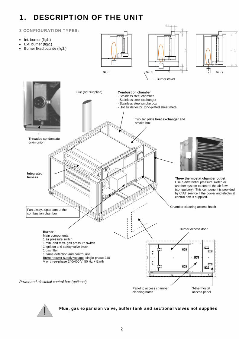
1. DESCRIPTION OF THE UNIT 3 CONFIGURATION TYPES: • Int. burner (fig1.) • Ext. burner (fig2.) • Burner fixed outside (fig3.)
Burner cover
Power and electrical control box (optional)
Flue, gas expansion valve, buffer tank and sectional valves not supplied
Three thermostat chamber outlet Use a differential pressure switch or another system to control the air flow (compulsory). This component is provided by CIAT service if the power and electrical control box is supplied.
Chamber cleaning access hatch
Tubular plate heat exchanger and smoke box
Combustion chamber - Stainless steel chamber - Stainless steel exchanger - Stainless steel smoke box - Hot air deflector: zinc-plated sheet metal
Threaded condensate drain union
Integrated bypass
Flue (not supplied)
Fan always upstream of the combustion chamber
Burner access doorBurner Main components: 1 air pressure switch 1 min. and max. gas pressure switch 1 ignition and safety valve block 1 gas filter 1 flame detection and control unit Burner power supply voltage: single-phase 240 V or three-phase 240/400 V; 50 Hz + Earth
Panel to access chamber cleaning hatch
3-thermostat access panel
2

DIMENSIONS
Ø D G
C1
Fig.1 Fig.2
Fig.3
Burner casing
3

TABLE OF DIMENSIONS
CHAMBER BURNERSP Max Kw AIR FLOW
4

dPa chamber
combustion circuitdPa chamber air
side Chamber weight kgUNIT
Volume of gas combustion products m3/ m3
GN 21.05 x (gas flow m3/h)
Propane 59.04 x (gas flow m3/h)
If the air-handling unit is equipped with a fan with a 2-speed or variable-speed motor, the control must ensure that the reduction in the air flow automatically causes a reduction in power.
PICTOGRAMS
Grounding compulsory Condensate drain siphon
Air flow Electric heater
2. INSTALLATION & CONNECTION GAS SUPPLY For a supply pressure greater than that recommended by the burner manufacturer, a pressure expansion valve must be installed to obtain the correct value while respecting the flow. The installation must have a gas supply cutoff valve for each burner and a manual valve located at the entrance to the premises, as per the conditions set out in article GZ 15 (fire safety regulations for establishments open to the public).
5

Schematic diagram of the gas system
Unit exterior Unit interior (when applicable)
Manual safety valve Expansion valve (option) (not supplied by CIAT)
Gas inlet Operating pressure Natural gas: MPA = 30 to 400 mbar expansion 18 mbar MPB = 0.4 to 4 bar expansion 18 mbar/300 mbar LPG: BUTANE expansion 28 mbar/118 mbar
PROPANE expansion 37 mbar/148 mbar
• Recommendation for calculating the pipework diameter, see following sections. • The pipework must always be installed with the greatest care. The local gas distribution prescriptions must be strictly
followed (in FRANCE comply with DTU 61.1). Burnt gas evacuation duct The duct should preferably be made from special gas-grade aluminium sheet with a purity of at least 99.5% or from stainless steel sheet metal. the duct is neither flush-mounted nor engraved but fixed only to the masonry using clamps. Each duct inlet is labelled to indicate that it can only be used for the evacuation of gas combustion products.
To burner
Flue duct (not supplied by CIAT)
Buffer tank (not supplied by CIAT)1 m maximum
The roof outlet complies with the usual standards. Minimum height of 0.40m above any ridge (sloping roof). Minimum height of 1.20m above a terrace roof (15% slope). A T-joint with an inspection cover is provided at the base. Double-wall ducts are recommended to prevent the formation of condensates. The duct cross-section must not be smaller than that of the unit's connection nozzle. The ducts are positioned at least 20 cm from any flammable material. The burnt gas ducts are made in accordance with the prescriptions of the CE directives.
Flame length and flue installation principle
int.
evac
uatio
n Ø
1
m m
in
Condensate draining Condensate drain Ø 3/4"
6

The sum of the pressure drops (flue duct + combustion chamber) must not exceed that authorised by the burner (refer to the table in the "Dimensions" section). The combustion gas outlet must extend at least 1 metre above the top of the roof. It is also necessary to check that the combustion gas cannot be recycled in the premises (allow a sufficient distance between the flue outlet and the building air inlets). The condensate drains will be connected to the gutter via a sealed duct. POWER SUPPLY AND ELECTRICAL CONNECTION All the electrical connections and wiring are configured and installed in accordance with the codes, local regulations and wiring diagrams located inside the units. Check that the available electrical power supply
corresponds to the characteristics on the manufacturer's plate.
Connecting the safety unit Safety thermostat mounted at the chamber outlet • 1st thermostat (automatic reset) Adjustable using the knob on the thermostat housing (range from 0 to 80°C). This stage can control the ventilation units in fresh air only operation (set to approximately 25°C). • 2nd thermostat (automatic reset) Adjustable inside the unit (range from 30 to 120°C). This stage provides overheating protection for the combustion chamber (set to approximately 90°C). The stage must be incorporated into the burner's control chain. • 3rd thermostat (automatic reset) Adjustable inside the unit (range from 40 to 100°C). This stage provides overheating protection for the combustion chamber (set to approximately 100°C). The stage must be incorporated into the burner's control chain.
Honeywell L4064N FAN and LIMIT thermostat
LIMIT-2 thermostat
Type TR2 Code 541302
White button
Automatic Button raised
LOAD
FAN Damper control
Automatic reset
LOAD FAN
25°LIMIT 100°C LIMIT
Manual reset Check that the strap
has been correctly cut
LINE LINE Red push button
Resetting FAN FAN LIMIT LIMIT LINELOAD LINE LOAD
Combustion chamber adjustment servomotor control (1-wire control) Temperature < 25°C: damper closed Temperature > 25°C: damper open
To be inserted in the burner control duct
7
Breaking capacity for each thermostat - 15 A (2.5 A) at 250 V - 10 A (2.5 A) at 400 V
• Only qualified personnel may carry out work on the thermostat. • When replacing an old thermostat with a new model, remember to carry out the wiring
modifications and run an operating test.
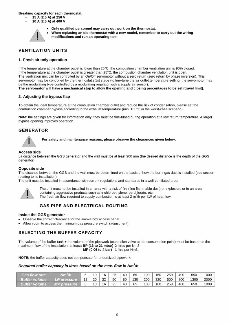
VENTILATION UNITS 1. Fresh air only operation If the temperature at the chamber outlet is lower than 25°C, the combustion chamber ventilation unit is 90% closed. If the temperature at the chamber outlet is greater than 25°C, the combustion chamber ventilation unit is open. The ventilation unit can be controlled by an On/Off servomotor without a zero return (zero return by phase inversion). This servomotor may be controlled by the thermostat's 1st stage (to fine-tune the air outlet temperature setting, the servomotor may be the modulating type controlled by a modulating regulator with a supply air sensor). The servomotor will have a mechanical stop to allow the opening and closing percentages to be set (travel limit). 2. Adjusting the bypass flap To obtain the ideal temperature at the combustion chamber outlet and reduce the risk of condensation, please set the combustion chamber bypass according to the exhaust temperature (min. 160°C in the worst-case scenario). Note: the settings are given for information only; they must be fine-tuned during operation at a low return temperature. A larger bypass opening improves operation. GENERATOR
For safety and maintenance reasons, please observe the clearances given below.
Access side La distance between the GGS generator and the wall must be at least 900 mm (the desired distance is the depth of the GGS generator). Opposite side The distance between the GGS and the wall must be determined on the basis of how the burnt gas duct is installed (see section relating to its installation). The unit must be installed in accordance with current regulations and standards in a well-ventilated area.
The unit must not be installed in an area with a risk of fire (fine flammable dust) or explosion, or in an area containing aggressive products such as trichloroethylene, perchlorate, etc. The fresh air flow required to supply combustion is at least 2 m3/h per kW of heat flow. GAS PIPE AND ELECTRICAL ROUTING
Inside the GGS generator • Observe the correct clearance for the smoke box access panel. • Allow room to access the minimum gas pressure switch (adjustment). SELECTING THE BUFFER CAPACITY The volume of the buffer tank + the volume of the pipework (expansion valve at the consumption point) must be based on the maximum flow of the installation, at least: BP (16 to 21 mbar) 2 litres per Nm3
MP (0.06 to 4 bar) 1 litre per Nm3 NOTE: the buffer capacity does not compensate for undersized pipework. Required buffer capacity in litres based on the max. flow in Nm3/h
Gas flow rate Nm3/h 6 10 16 25 40 65 100 160 250 400 650 1000 Buffer volume LP pressure 12 20 32 50 80 130 200 320 500 800 1300 2000 Buffer volume MP pressure 6 10 16 25 40 65 100 160 250 400 650 1000
8

Capacity in litres per linear metre of pipe
Bore (mm) 25 32 40 0 50 50 65 65 80 80 100 100 125 125 150 150 200 200 Steel 0.66 1.08 1.4 2.3 3.8 5.3 9 13.3 19.9 33.7
Copper 0.53 0.85 - 2.1 - - - - - - Polyethylene 0.53 0.83 - 2.07 - 4.2 6.3 7.8 13.4 21 NOTE: the buffer tank is required if the volume of the pipework is less than the buffer capacity calculated. GAS PIPEWORK DIAMETER SELECTION AID
Correction factor depending on altitude and temperature
Barometric pressure + gas pressure 273 F = X
1013 273+T° of gas
F normal average Natural GAS l 020 mbar F = 1 LPG 37 mbar F = 1 LPG 150 mbar F = 1.1 Natural GAS 300 mbar F = 1.25 GAS FLOW RATE CALCULATION NATURAL GAS
Generator power (kW) Flow rate in Nm3/h =
NCV x efficiency If the temperature is not 0°C, the gas flow rate read on the meter must be corrected using the F coefficient determined above. PROPANE GAS
Generator power (kW) Flow rate in kg =
13 kW/h x efficiency
Flow rate in Nm3/h = flow rate in kg/h x 0.5 Nm3/kg
Reminder: 1 kg of propane = 13 kW/h or 1kg/h of propane = 13 kW 1 K: 0.5 Nm3 / kg =
1.98 kg/Nm3 (1.98 kg/Nm3 = density of propane) Propane gas: to use the pipework diameter selection tables below, apply a coefficient of 1.66 to the calculated flow rate
Corrected PROPANE GAS flow rate = propane flow rate x 1.66
Reminder: the pipework diameter based on the pressure drop (dp), depends on 3 criteria: • Pressure downstream of the expansion valve • Maximum flow rate • Equivalent pipe length.
9
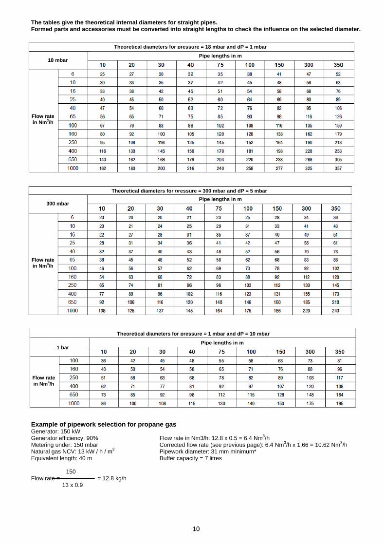
The tables give the theoretical internal diameters for straight pipes. Formed parts and accessories must be converted into straight lengths to check the influence on the selected diameter.
Theoretical diameters for pressure = 18 mbar and dP = 1 mbar
Pipe lengths in m18 mbar
Flow rate in Nm3/h
Theoretical diameters for pressure = 300 mbar and dP = 5 mbarPipe lengths in m
300 mbar
Flow rate in Nm3/h
Example of pipework selection for natural gas Generator: 150 kW 150 Generator efficiency: 90% Flow rate = = 16.6 Nm3/h Metering under: 300 mbar 10 x 0.9 PCl Natural gas: 10 kW / h / m3
Equivalent length: 40 m Pipework diameter: 31 mm minimum Buffer capacity = 1 litre per Nm3/h (16.6 litres)
1 bar
Flow rate in Nm3/h
Pipe lengths in m
Theoretical diameters for pressure = 1 mbar and dP = 10 mbar
Example of pipework selection for propane gas Generator: 150 kW Generator efficiency: 90% Flow rate in Nm3/h: 12.8 x 0.5 = 6.4 Nm3/h Metering under: 150 mbar Corrected flow rate (see previous page): 6.4 Nm3/h x 1.66 = 10.62 Nm3/h Natural gas NCV: 13 kW / h / m3 Pipework diameter: 31 mm minimum* Equivalent length: 40 m Buffer capacity = 7 litres
150 Flow rate = = 12.8 kg/h
13 x 0.9
10

Dimension based on bore and material The smallest required bore is selected (see table of standard dimensions below) based on the necessary theoretical internal diameter and the type of pipe. The section capacity is calculated based on the selected bore and the section length, and compared to the required buffer capacity. If the section capacity is less than the required buffer capacity, a larger bore should be selected or a buffer capacity created. The actual bore to be used is defined based the material used and the standard bores available for this material.
Dimensions based on standard bore and material
Steelin accordance with NF A 49.110 up to DN 20 inclusiveand in accordance with NF A 49.111 from DN 25
Copper in accordance with NF E 29.591
Bore
DN mm Inch(es) thickness mm external Ø mm external Ø mm thickness mm
Capacity in litres/metre of pipes depending on their type
Bores mm
Steel
Copper
3. COMMISSIONING If you have not subscribed to CIAT commissioning: all the startup operations must be carried out by approved personnel. The combustion equipment is installed in accordance with current regulations relating to its category. • Check the sealing of the gas ducts before connecting them to the equipment using a soapy solution, placing
the ducts under pressure. • When all the connections have been made, bleed the air from the gas supply duct. • Adjust the burner pressure according to the generator pressure. • Check that the flame does not touch the back of the chamber.
Flame length (m) = w x 0.06 (with 15% excess air)
If control is included, refer to the corresponding manual.
4. SERVICING AND MAINTENANCE If you have not taken out a CIAT Servicing and Maintenance contract, these operations must be carried out by approved personnel. Before servicing: • Cut the gas supply • Cut the electrical power supply • Ensure that the AHU fan is stopped
Do not use water to clean electrically-supplied parts
No equipment may be modified or replaced without the manufacturer's authorisation
11

Components Action Frequency
GGS • Check the equipment's sealing • Check the gas supply pipework's sealing • Check that the burner, safety and regulation
devices are operating correctly.
1 year
Exhaust ducts and smoke box • Chimney sweeping • Cleaning 1 year
Connections • Check the tightness of all connections 6 months
Electrical cable and wires • Visually check the condition of the components 6 months
5. PROBLEM/CAUSE/OPERATION Refer to the burner manual
12

6. CERTIFICATION


Non contractual document.With the thought of material improvement always in mind, CIAT reserves the
right,without notice, to proceed with any technical modification.
CIAT ServiceTel. : 08 11 65 98 98 - Fax : 08 26 10 13 63 (0,15 € / mn)
Siège socialAvenue Jean Falconnier B.P. 14
01350 Culoz - FranceTel. : +33 (0)4 79 42 42 42Fax : +33 (0)4 79 42 42 [email protected] - www.ciat.com
Compagnie Industrielled’Applications Thermiques
S.A. au capital de 26 728 480 €R.C.S. Bourg-en-Bresse B 545.620.114
4Łme de couv.qxd 30/07/2009 10:30 Page 4