n83-23361 strength criteria for composite materials …
TRANSCRIPT
N83-23361
STRENGTH CRITERIA FOR COMPOSITE MATERIALS (A LITERATURE SURVEY)
F. Roode
Scitran Santa Barbara, California
December 1982 | .hr,jjro~e<i for piiDÜc reieassi
U.S. DEPARTMENT OF COMMERCE National Technical Information Service
m
JI

THIS DOCUMENT IS BEST
QUALITY AVAILABLE. THE
COPY FURNISHED TO DTIC
CONTAINED A SIGNIFICANT
NUMBER OF PAGES WHICH DO
NOT REPRODUCE LEGIBLY.

NASA TECHNICAL MEMORANDUM NASA TM-77001
N83-23361
STRENGTH CRITERIA FOR COMPOSITE MATERIALS
(A LITERATURE SURVEY)
F. Roode
Translation of "Sterktecriteria Voor Composietmaterialen (een Literatuur Overzicht)'/ Instituut TNO voor Werktuig- kundige Constructies, Delft (Netherlands), Report IWECO 5071104-80-1; TDCK-75128, January 1980, pp. 1-46.
(NASÄ-TM-77001) STEENGTB CBITIBI1 FOB N83-23361 COMPOSITE HÄTEBIÄLS (& LITEKÄTÜIE SBBVII) (National aeronautics and Space Administration) 5t c HC &CU/HE 1.01 CSCI 1 ID ünclas
G3/2«» 11609
"REPRODUCED BV ,...„,,, NATIONAL TECHNICAL INFORMATION SERVICE
US. DEPARTMENT OF COMMERCE SPRINGFIELD. VA. 22161 '
NATIONAL AERONAUTICS AND SPACE ADMINISTRATION WASHINGTON, D.C. 205^6 DECEMBER 1982

ORIGINAL PAGE fS OF POOR QUALITY
ITANOAAO TlTlt f>ACC
1. R»»««t N«. NASA TM-77001
I. Ck*«fCMMal Ace»itta« M».
4" T'sraENGTH CRITERIA FOR COMPOSITE MATERIALS (A LITERATURE SURVEY)
7. A»'k*i<t)
F.. Roode
). Rtclpimt'i CaUUf N«.
S. *•••»• 0«i» , „ . „ December 1982
6. P«ff*rmlnf Orf«rtlc«tl«A C«4«
1. P»('»'min§ 0'|*niiatl*n R*f•«* H«.
10. W.,k Ur.ll N«.
9. P«r(»>mih« Of|«ni•«•!•(» Nam* art*) AMr««t
SCITRAN Box 5456
Barhara PA 0710«
12. Sf*"«»'i'<9 *••"*? Mama and AMf*M ... National Aeronautic» and Spaca Adainiatration Waanington, D.C. 20546
II. Ctnlraat at Otwil H». WASw> , T542
II Tjaa at Raaatf ana1 f •fiaa' Cavaraa1
Tranalation
14. Sao««**!*« Aa*a*r Caata
IS. S*>aIMMIITIHataa
Translation of "Sterktecriteria Voor Composietmaterialen (een Literatuur Overzicht)", Instituut TNO voor Werktuigkundige Constructies, Delft (Netherlands), Report IWECO-50711U4-80-1; TDCK-75128, January 1980, pp. 1-46. (N82-25333)
I*. Aa»traat*
Literature concerning strength (failure) criteria for composit materials is reviewed with emphasis on phenomenological failur criteria. These criteria are primarily intended to give a good estimation of the safety margin with respect to failure for arbitrary multiaxial stress states. The failure criteria do not indicate the types of fracture that will occur in the material. The collection of failure criteria is evaluated for applicability for the glass reinforced plastics .used in mine detectors. Material tests necessary to determine the parameter in the failure criteria are discussed.
17. Ray Va>aa (StfMtM kr AatlMlWt
>*• Saaaritv Clataif. (a* *ta
Uadaaaifia* l_
Unclassified - Unlimited
at. Saavrlt* Claa*!*. (a* «Ma Mflat
Oaelaaalfiad It» Ma. a* Paaaa
51
aa. **m
ii

NOTICE.
THIS DOCUMENT HAS BEEN REPRODUCED
FROM THE BEST COPY FURNISHED US BY
THE SPONSORING AGENCY. ALTHOUGH IT
IS RECOGNIZED THAT CERTAIN PORTIONS
ARE ILLEGIBLE, IT IS BEING RELEASED
■'I N THE INT E RE ST: OF MAKING A VAIL A B L E
AS MUCH INFORMATION AS POSSIBLE.
t\.<\.

CONTENTS
page
1. Introduction 1
1.1 Micromecbanical approach 1
1.2 Macromechanical approach 2
a. Maximum stress theory 3
b. Maximum tension theory 3
c. Deformation energy 4
d. Tensor polynomials 12
2. Choice of a failure criterion 20
3. Experiments 2 8
4. References ■ 31
5. Figures .3 4
6. Appendix A: Stability for the Franklin
criterion ^2
*/i
*Numbers in margin indicate pagination of foreign text
in
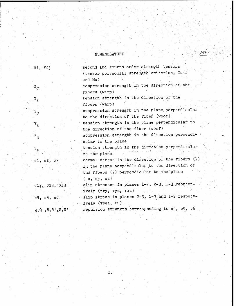
NOMENCLATURE /il
Fia pij■ second and fourth order strength tensors
(tensor polynomial strength criterion, Tsai
and Mu) X compression strength in the direction of the
fibers (warp)
X tension strength in the direction of the
fibers (warp) Y compression strength in the plane; perpendicular
to the direction of the fiber (woof)
Y tension strength in the plane perpendicular to
the direction of the fiber (woof)
Z compression strength, in the direction perpendi-
cular to the plane
Z tension strength in the direction perpendicular .
.to the plane
0I, 02," 03 normal stress in the direction of the fibers (1)
in the plane perpendicular to the direction of
the fibers (2) perpendicular to the plane
( 0, oy, oz)
012, 023, ;0l3 slip stresses in planes 1-2, 2-3, 1-3. respect- -.
ively (xxy, xyz, TXZ)
04, 05, 06 " slip stress in planes 2-3, 1-3 and 1-2 respect-
ively (Tsai, Mu) -
Q,Q',R,R',S,S' repulsion strength corresponding to 0^, 05, 06
iv

INTRODUCTION A
In the literature, different approaches have been found to
study failure phenomena in composite materials.. The two most
important approaches may be found in [2].
1.1 Micromechanical approach
In this approach, the starting point is the study of the fail-
ure behavior of the components involved (matrix material fiber and
finally the layers or lamellae).
The failure behavior of the different layers is subsequently
combined into the failure behavior of the complete laminate.
The description of the failure in a composite material is a
fairly complex task in which complete computer programs must be
used to calculate the strength tension relation. To increase the
practical applicability of such an approach,, sometimes a simplified
approach is used in which only two points on the stress-tension
curve are calculated. These are the points at which the first fail-
ure occurs in the composite material (comparable to the fluid ten-
sion in a metal) and the final failure stress. The last point is
determined by a so-called "netting theory" in which it is assumed
that-the fibers can only absorb normal stresses. Even in this sim-
plified case, it is hardly possible to apply such failure analyses
for practical engineering purposes. In practical engineering, it
is always necessary to obtain, on the basis of simple relationships
between mechanical parameters, an impression of the safety of a
structure with regard to failure.
The inapplicability of the theory applies even more strongly
to the approaches often found in the literature in which failure
■ mechanics and static considerations are used. Especially for glass
fibers (as used in mine detectors) a static approach for the brittle

failure behavior is inadmissible (because of the brittle failure
behavior).
In [1], we find an overall survey of the study in the area of
the micromechanical approach. The same publication also indicates
that the usefulness of the micromechanical approach resides mainly
in the possibility of choosing between different compositions of .
the composite materials.
Since for mine detectors the material must be considered basic-
ally firm, here actually this study loses much of its usefulness.
11 The benefit of the micromechanical study must, within the
framework of the study of the composite material for mine detectors
be sought in the possibilities of achieving by means of these theor-
ies an estimate of the reliability of certain types of experiments.
In the micromechanical approach, the experiments are carried
out in such a manner that only one form of failure occurs. In the
macromechanical approach to be considered further on, much less
attention is paid to this.
To make sure that a certain failure criterion gives conserva-
tive results in all cases, however, it is certainly recommended to
conduct experiments also for one failure form so that there is a
clear definition of the moment of appearance of the "failure".
1.2 Macromechanical approach
In the macromechanical approach, the primary purpose is to
achieve a fairly simple criterion presenting the failure of the
total laminate as a function of the load state. The number of cri-
teria formulated in the course of time is very large. Reviews of
such criteria may be found in [7,8,93.
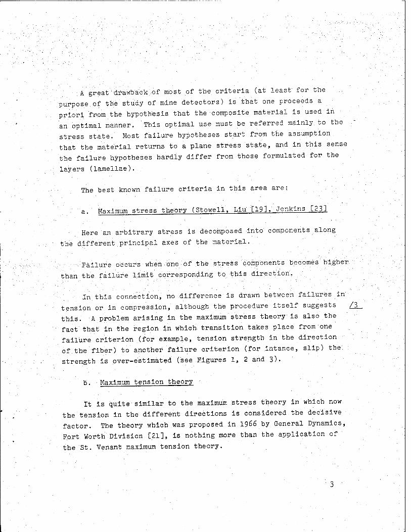
■A great drawback ,of most of the criteria (at least for the
purpose,of the study of mine detectors) is that one proceeds a
priori from the hypothesis that the composite material is used in
an optimal manner. This optimal use must be referred mainly to the
stress state. Most failure hypotheses start from the assumption
that the material returns to a plane stress state, and in this sense
the failure hypotheses hardly differ from those formulated for the
layers (lamellae)..
The best known failure criteria in this area are:
a. Maximum stress theory (Stowell, Liu [19], Jenkins [231
Here an arbitrary stress is decomposed into components along
the different principal axes of the material.
Failure occurs when one of the stress components becomes higher
than the failure limit corresponding to this direction.
In this connection, no difference is drawn between failures in
tension or in compression, although the procedure itself suggests /3_
this. A problem arising in the maximum stress theory is also the
fact that in the region in which transition takes place from one
failure criterion (for example, tension strength in the direction
of the fiber) to another failure criterion (for intance, slip) the
strength is over-estimated (see Figures 1, 2 and 3).
b. Maximum tension theory
It is quite similar to the maximum stress theory in which now
the tension in the different directions is considered the decisive
factor. The theory which was proposed in 1966 by General Dynamics,
Fort Worth Division [21], is nothing more than the application of
the St. Venant maximum tension theory.

ORIGINAL PAGE IS c. Deformation energy OF POOR QUALITY
The overwhelming majority of phenomenological failure cri-
teria for composite materials are derived from deformation energy
considerations and in particular the form changing energy.
The basis for this was obtained by Von Mises (1900) for Iso-
tropie materials with the formula
■V-(l,x -,,y)2 + (,y -,,z)2 + ( „z W < 6(lxy2 + TVZZ + Tzx2) = Uh* .
Although Von Mises had intended the criterion primarily for
the flow of material, in the course of time for metals, it is only
used to describe the flow.
In the area of composite materials, nevertheless, the applica-
tion of deformation energy criteria is still maintained to describe
the failure. As long as the materials considered are brittle, this
is a reasonable starting point. A number of new criteria have been
derived'from the'Von Mises criterion. Strictly speaking, most of
the criteria do not..give &.real deformation energy, but rather a relation in stress variants. For convenience, these, criteria are
also called deformation energy because they are mostly an extension
of the Von Mises. formulation. • •
Hill [6] extended subsequently the Von Mises criterion to ani-
sotropic materials in the form:
F( ay- ,,z)2 + G( >rz- rrx)2 + H( „x-oy)2 + 2L-c2yz + 2fit2zx + 2\^Ky = 1 ÜL
in which P, G, H, L, M and N are material parameters.
In this equation (2), it is also assumed implicitly that:
—the material is orthotropic
--there is no difference between tension and compression
strength; with the relation Xfc = XQ = X; Yfc. = YQ = Y, it was
then simple to derive:

2F - I2 + I2 - A, Y' Z' X"
2G
2H = I ±1-1 X2 Y2 Z2
2L 1
Q
2M '. ; R
2N = I S
■ORIGINAL- PAGS fS 0F POO?? QUALITY
(3)
The six parameters of the failure criterion are thus deter-
mined entirely by the three tension strengths and the three slip
strengths for the mutually perpendicular directions of the mater-
ial.
To make it possible to compare with the following failure
criteria, it is convenient to write the Hill theory in the follow-
ing form: Fi jc/i </j = 1 i = 1,2 ....6 (4)
The repetition of the sub-indices is reduced to the summation
convention in which the sum is measured over all the values of the
sub-indices (1 to 6 inclusively).
The term Fij can then be considered as a 6x6 matrix of the
form:
~l~2 2 V 2 X Y Z
1
7
:V +I -•! ) T(~2 2 2' 2 Z X Y
2 Y
0 0 n
1
? 1
R2
l
s2-
tJ)
(5)

ORIGINAL PAGE IS CP'PCOR QUALITY
The greatest drawback of the Hill criterion'1 IS' that ..it is- ; /
impossible to differentiate between tension and compression-
strength, while it was just, established for composite materials
that there can be a great difference between the two. values... .
One of the first attempts to include also the compression
forces of the material in the failure criterion was made by Marin'-:
[10]. The latter used, to this end, the Hill criterion written in
the main tensions (indicated for convenience here as ax , ay , az
O (.rx1 - ay1;] 2 +[to("y1 - ,,z1)]2 ♦[iccK1 -„x\j\?- = 2<'*y2
To eliminate the differences in tension and compression, he
modified the relation into:
(ax1 - a)2 * (ay1 - b)2 + («z1 -c)2 +
g|("x' - a) (<ryl - b) +(,/y1 - b) (»z1 - c).+ (7)
-zl - c) ( <;y! - a] 2
= <! X V
The difference from the previous Hill relation is actually only 11 1
that three terms have been added, specifically, ax , ay and az .
If the failure criterion is considered as a surface in the
six-dimensional stress space, the addition of linear terms in the
failure criterion implies that the origin of the rupture stress
surface is shifted.
If we attempt to relate such a failure criterion (with shifted
origin) with mechanical phenomena, this means that it is assumed
that an internal stress is the cause of tbe\difference in tension
and compression force.
Prom the more micromechanically directed failure investiga-
tions, it is known [1] that the difference in the two strengths is
mostly caused by a difference in the failure mechanism (in com-
pression, it is not the material stress/strength which is decisive,
but the danger of cracking the fiber).

ORIGINAL PAGE IS OF POOR QUALITY
The above illustrates the earlier remark that no attempt was
made to describe or explain the failure mechanisms with the fail-
ure criteria.
A great drawback of the Marin theory is the fact that the
failure criterion is given in terms of main stresses. Such a
direction of the main stress does not have to coincide with the
main directions (symmetry planes) of the material, see Grescszuk
[2]. The problem is that then the tension/compression strengths
must be known in other directions than the main directions of the
material, to be able to determine the parameters of the failure cri-
terion. Practically, this then raises many problems which the Marin
theory had hardly touched.
The overwhelming majority of later authors recognized the prob-
lem in the Marin theory and have, therefore, deviated from the more
general formulation of the Hill criterion C51.
Some of these theories are discussed below.
Tsai and Azzi proposed a simplification of the Hill criterion
by assuming that the composite material is normally used in an opti-
mal manner and is, therefore, in a flat stress- state.
Assuming a3 = xl3 = T23 = ° (5) is converted into
A second hypothesis which is often put forward for composite
materials is that a cross-section perpendicular to the fiber direct-
ion should behave isotropically, i.e., Y = Z.
It is apparent from the comparison that most pass through the
Tsai-Azzi criterion.
o r »I«2 , P2 T12 _ . —7T - n— + —ö + —o~ " i
yc x<i Y^ r
/6

ORIGINAL PAGE IS OF POOR QUAL.TY
For the glass fabric composite materials considered here,
this last designation cannot apply directly since the hypothesis
of isotropism in the cross-section is not maintained.
The more general notation (8) should basically be defensible
still-were it not that bending any slip may practically also occur
perpendicularly.
A method proposed by Tsai and Azzi [2] to solve this problem
consists in applying the criterion (9/8) by layer (lamella).'
But it is very doubtful whether this approach can be imple-
mented for practical purposes. It would specifically be necessary
to establish the stress state per layer.
This might be done for composite materials with exact composi-
tion (winding techniques)(apart from the fact that it would involve
an enormous amount of work). For composites with more arbitrary
structure, this approach would hardly be reasonable. The reason
why the application of the Tsai-Azzi criterion is not reasonable
for the glass fabric considered here is the fact that it.is not at
all .clear whether the failure in a layer is determined by a flat
stress state. Specifically, the glass fibers in such a layer are
not straight so that the third stress component may also have an
effect.
The last drawback of the Tsai-Azzi criterion is the same as
for the Hill criterion and concerns the fact that no differentia-
tion is made between tension and compression strength.
For the sake of completeness, another simplification of the
Tsai-Azzi criterion is indicated.
Indeed, in many investigations, it was found that the inter-
action term from (9) olo2 may be eliminated in many cases so that
x2
/7

ORIGINAL PAGr ,s
OF POOR QUALITY
the Tsai-Azzi criterion is converted into the Norris-Puck
criterion in the form
4 +-4 + T-4- -i <io> This aspect will be discussed in greater detail further on.
Ä failure criterion which can avoid most of the above-men-
tioned drawbacks was established by Hoffman [11].
'■■'- Hoffman also started from the original Hill criterion (2) and
added to this relation a number of linear stress terms to be able
to eliminate the difference between tension and compression: ;:
Cl'[.-2 -"3)? + C2 (»3 -"P2 ■< C3 ("1 - <>2)2 (-11')
A- C4"l ->■ C5"2 + CG'3 + C7»a2 ' C!;,M32 + C9"i?'' - 1
Such a failure criterion has thus nine material parameters /8_
and therefore a large number of tests are needed to establish these
material parameters.
With the results of
—three tension tests Xt, Yt, Zt
—three compression tests Xc, Yc, Zc and .
—three slip tests Q, R, S the following relationships may
be established:

C.l
C2
C3 =
1 '" YtYc ZtZc
1 . ■ 2;. XtXc
1 -1'. 1". 1 z ZtZc XtXc YLY,-
J_ I-L.-.L . 1 2 ' XtXc YtYc
C4 = -L- _J_. Xt Xc
15 "-X _1 ' Y.t Yc
C6 = __i - _ l_
Zt Zc ■
C7 = -L Q
C8 = -L R'
ZtZc
ORIGINAL PAGr R
(12)
C9 =
The failure criterion is established completely with these
nine .parameters/tests.//: .■■■>■
This criterion has a number of remarkable aspects: the fact
that no difference- is made between positive and negative slip
strength. This possibility is left open in many of the criteria
discussed below. It is also doubtful whether this extension is /9_
proper for the orthotropism considered here.
It may also be noted that the equation (12) is a quadratic
equation so that the failure surface in the stress space is ellip-
tical and convex (with origin not necessarily at zero).
With the definition of the Hoffman criterion practically, the
maximum is retained of the original Hill criterion. But actually
10

ORIGINAL PAGE IS OF POOR QUALITY
of the Hoffman criterion it should be.stated that this criterion
has no physical basis but is rather a mathematical approximation.
Many researchers have observed subsequently that a problem which
arises with all the criteria considered here consists in the fact
that the failure criteria are defined with regard to the princi-
pal axes of the material.
This implies that, in the calculation of an actual structure,
the arbitrary stress state must be converted to the stress compo-
nents in the main directions of the material.
It may also be established now that the problem is not. so im-
portant for the orthotropic glass fabric reinforced composites con-
sidered here. If in this connection we refer to final element cal-
culations, it happens in most cases that the main direction of the
material coincides with the main direction of the elements.
This can. also be a problem for other anisotropic materials.
For the sake of completeness, we will also discuss below the approx-
imations in. which the conversion of the stress aces is resolved with
respect to the tensorial algebra.
For the purpose of comparison with other failure criteria, con-
sequently the Hoffman criterion is also written again the matrix
form which like equation (4) can also" be written as
with i = 1, 2...6.
Fi ,;1
mc-t i
Ftj''i"j -; 1
(13)
Here we have Fi J_. _ J_
XI Xc
I . J_ Yt Yc
i — J_
It
0
0
0
Zc
(14) /10
11

and ORIGINAL PAGE 15
OF POOR QUALITY
FiJ =
■1 ! 1
XtXc 2 XtXc XtYc ZtZc
YtYc
1 -1 1 '► y - i
ZtZc 2 ZtZc XtXc YtYc
-1 1 ♦ l - l-
2 r't.Yc ZtZc . XcXt
ZtZc .
0.0
0 0 0
<;2
d. Tensor polynomials /ll
The following failure criteria are purposely no longer cal-
culated to the deformation energy approximation.
Although a number of the theories can be reduced to deforma-
tion energy in the definition of the failure criteria, the start-
ing point is a purely mathematical description of the failure cri-
terion. The Hoffman criterion can be considered as,a transition
area (no tensors are used there yet).
One of the first theories in this area was formulated by
Goldenblat and Kopnov [5] with the relation:
12

■;■■■-■■■<.-■'■■■ ;-• ■:-.■■■-.■ ORIGINAL PAGE ß OF POOS Q'JALTv
(ri.ji'1 + ffij"i"j) ' * (fi'!'.'•■ ioj«. ) - 1
(15)
in which once again the summation convention is adopted with
regard to the subindices:
Here it was also assumed:
Pi = strength tensor of the second order
Fij = strength tensor of the fourth order
. Fijk = strength tensor of the sixth order
The conversions of the tensor in the rotations of the axes
are known here from tensorial algebra. The great advantage of ten- .
sor polynomials is also the fact that the criterion is defined with
respect to an arbitrary system. Goldenblat and Kopnov have consi-
dered in particular a special case of equation (15) with
<> = i, .; - \, y = - "
so that equation (15) is converted into:
r • xr ■ • , (l6)
Tsai and Wu (4) have indicated that the square root in formula (16)
is very impractical, since the result is a + sign. The Goldenblat
and Kopnov criterion is, therefore, best applied in the quadratic
form: . -.. -^ — Ki.'i f ri.;r;i"J - (Fi»i) - 1 (17)
But even this form of the Goldenblat and Kopnov criterion is not
much used practically. A problem which arises for this criterion
refers to the definition of the interaction term Fij.
If these terms are determined directly with experiments, it
may occur that the failure surface, in the stress space is no longer
closed (elliptical) but is converted into a parabolic or hyperbolic /12
surface which may lead to unrealistic theoretical strength proper- '
ties .....'■
This phenomenon was also indicated by Ashkenazi [20]. The
above-mentioned problem becomes even greater if the third power
term (Fijkiajak) is included.
13

ORIGINAL PAGE IS OF POOR QUALITY
"Apart from the fact that in that case a very large, number, of ,.
interaction terms have to be determined, such a cubic equation may. ,
often lead to a nonclosed failure surface in the stress space.
To solve the above-mentioned problem Tsai and Wu [4] estab-
lished a criterion which is more general than the Goldenblat-Kopnov
criterion, simpler to apply and results in a closed (elliptical)
failure surface in the stress space.
The Tsai-Wu criterion has the form; (18)
Fioi + Fitn'wj = 1 (i = 1, 6).
Here, too, the summation convention is applied with regard to the sub-indices. To take into account the fact that the failure surface is elliptical (in the stress state), the following stability
requirements are imposed:
Fii Fjj - Fij2 4 0 (19)
In this connection, the striking detail is that the original
authors also accepted the equality signs in equation (19)» while
the later investigators established, on the basis of a more graphic
interpretation of the failure surface (14), that the equality sign
was not acceptable either.
It should be noted that the general equation (16) contains alto-
gether (basically) 42° of freedom (unknowns). This number of unknowns may be reduced to a considerable extent by assuming that
the Fij terms are symmetrical. Such an assumption may be made if
we start from the hypothesis that there is a so-called F(ai) failure
potential. Here the terms Fij are defined by:
.:..— -? 2,::.-7 r;. (20) Fij = trf/ntiriti =>-f/n'ym = Fjr
The assumption of a failure potential implies nothing other
than the assumption that the failure phenomenon is independent of
the load path. Such a hypothesis is made essentially for all the
14

ORIGINAL PAGE 13 OF POOR QUALITY
above-mentioned failure criteria. How far this assumption is
justified depends both on the type of material and the phenomenon
described as failure criterion. If the failure criterion is used A3
to describe a kind of fluid limit (or the first point at which a
break occurs anywhere in the laminate), this assumption is generally
valid.
If this criterion is used to describe the final total failure
of the material, the assumption with regard to the independence of .
the load path is less valid. In such a case, specifically the final
failure is preceded by plastic deformations which are to. some extent
path-dependent. Nevertheless, the failure criterion may still be
valid for the so-called radial stress paths. In this connection, .
radial stress paths should be considered as paths in the stress
space in which the corresponding ratio of the stress components
would remain the same.
Since the failure criteria formulated in this report must be
considered primarily as a design criterion and not so much a criter-
ion in which very exact predictions must be made on the failure
stresses occurring, such path-dependent effects may be left out of
consideration preliminarily. The simplification taken then is that
the path-dependent effects are included in the safety factors.
With the assumption of formula (-20), the number of unknown
parameters was reduced from 42 to 27 (6 for Fi and 21 for FiJ). A
still greater reduction in the number of degrees of freedom may be
achieved by starting from orthogonal material properties which is
directly permissible here for the material considered.
. With such an isotropism, it may be stated directly that a con-
nection between the normal and slip stresses may not arise so that
terms such as Fl6 may be equal.to zero. It may also be stated that
if the reference system of axes coincides with the material (strength)
main directions, we have [7]: F4 = F5 + F6 = 0.
15

ÖRiG!NAL''PA<w »s OF POOR CUÄUTV
In the matrix form, the relation (18) is then written as
follows:
Fi
Fl
F2
F3
0
0
0
Fij
J
Fll F12 F13 0 0 0
F22 F22 0 0.0
F33 0 0 0
F44 0 0
F55 0
F66
(21)
Ä
The parameters in equation (21) must be obtained again from
tension and compression tests. "Simple" single axis failure tests
may be used for the terms of Fi and for the diagonal terms in Fij.
As an illustration: When loading in direction 1, the following values
are found for tension and compression strength respectively
a.l - Xt and al = -Xc (let on the minus sign). .
For equation (18/21), we may write
Xt2 Fll + Xt Fi = 1 and
Xe2 Fll - Xc Fi = 1
from.which it follows that:
F1 " XT * YS and F11 = xtlc- (22a)
By a similar method, we may obtain for the other material
directions
F2 = J_ . J_ Yt Yc
F3 = J_ _ J_ Zt Zc
F44 = 1 F55 =-• AT
F22 =
F33
_1_
YtYc
1
ZtZc
2 . F66 = -; 1
(22b)
16

Here it may be assumed directly that for the orthotropic
material there is no difference between the so-called positive
and negative slip.
A comparison of relations (22) with those from the Hoffman
criterion (14) shows that, the characteristics discussed up to now
are exactly the same.
The great difference between the Hoffman criterion and the
Tsai-Wu (tensor polynomial) criterion lie in the definition of the /15
cross-terms F12, P13 and F23-
.For the Hoffman criterion, the cross-terms are dependent para-
meters which are established completely if the parameters in equa-
tion (22) are determined.
In the Tsai-Wu criterion, the cross-terms are independent mat-
erial parameters which have also to be determined by separate exper-
iments.
The authors of the criterion (Tsai and Wu) consider that the
advantage of this independence in the cross-terms resides mainly in
the greater flexibility of the criterion to achieve a proper pre-
diction for the failure strength for multiaxial stress states also.
In this connection, Tsai and Wu [7] state that most- failure criteria
describe well the uniaxial failure strengths, but raise problems in
the multiaxial stress state. The similarity of the form of the
Hoffman and Tsai-Wu criteria with regard to the uniaxial failure
strength seems to confirm this view. But even the more flexible
formulation of the Tsai-Wu criterion leads rather to a shift of the
problem than to its solution. Specifically the problem which now
has to be solved for the Tsai-Wu criterion is the question as to
which experiment is most suitable for determining the cross-terms.
The historical developments in this connection are sufficiently
illustrative.
17

.ORIGINAL PAGE IS OF POOR QUALITY
The Russian investigators used primarily tension and com-
pression tests on a so-called 45° blank (the material axes form
an angle of 45° with regard to the main axes of the blank).
If for plane 1-2 the experimental results are indicated as
Ut and Uc, we find for F12
ri2 = 0
I + !i£ \xt Xc
+ Yt -i> '-(
, XtXr ' +4
YtYc S*
or
F12 'r. .1. 1 Ut2 j
1 - y_t. (t Xc 7-
Yt -t) ■f (--■*■ UtXo , 1 X .1
YtYc 'S'1
(23)
In [12]., Tsai and Wu also indicated that these experiments
were hardly sensitive for a variation in F12 (see Figure 4). In /l6
this publication, the authors also say that much better results
may be expected for a positive slip test on the .45° blank. For an
experimentally determined value V, F12 is defined by:
-1 1 K '!■■
-vr-L- . j_ . .-LV-L) - V2(. l ■ + T )
2VL Xt Xc Yt Yc .XtXc YtYc J F12 = —4 J. - Vf ---—-—+ — )-V-( .-^-+ J (24 V
2Vd Xt Xc Yt Yc XtXc: YtYc J. K '
But the practical results seem to be very disappointing, even
for such an experiment.... .. ,.
In [14], Collins and Crane explained.with a purely graphic
interpretation of the Tsai-Wu criterion that the positive slip exper-
iments on 4"5° blanks probably do not provide the desired results.
This type of slip experiment is indeed hardly used any longer.
An additional problem in the experimental determination of the
cross-terms depends on the fact that the stability criterion (19)
has always to be satisfied. Thus, it can happen very often that
the experimentally determined value cannot be applied to the cross-
terms.
This is illustrated by the results of Pipes and Cole [13] when
the cross-terms F12 are determined with off-axis experiments (exper-
iments in which the material forms an angle with the main axis of the
blank).
18

Of the four experimentally determined values of F12, only.one
value seems to satisfy the stability criteria: On the basis of
these results, the conclusion may, therefore, be drawn immediately
that it is impossible to determine the cross-terms with these
experiments.
In later publications, especially by Wu [7 and 17] alternative
procedures are proposed to determine the values of the cross-terms.
In these procedures we start from a really biaxially stressed blank
(stress al, c2). In'Wu's procedure, there must be an optimal bi-
axiality ratio B B = ol/o2) determined for which the value P12 can
be defined.
Unfortunately, the optimal value of B depends on the value of
F12, so that an iteration process must be used (with the correspond-
ing number of tests).
In the same publications, it is also indicated that a decision
may be taken to include terms of the higher order (Fijk, Fijkl, /17
etc.) in the failure criterion. This decision depends on the (ex-
permentally determined) value of Fij with regard to the precision
of the solution (determined on the basis of the hypothesis that
the spread in experimental failure experiments is, for instance,
approximately 10$). If the value of Fij is greater than the preci-
sion of the solution, it will be necessary to include additional
higher terms. This is not related to the fact that the situation
becomes even more complicated when these terms of higher order must
be included. Even for these terms of higher order, optimal multi-
axial experiments must be defined with the necessary interaction
work concerned. Moreover, the terms of higher order (Fijk) still
depend on the lower order terms Fij. According to Wu, the Fij terms
can be determined first, after which the determination of the Fijk.
terms no longer affects the values of Fij.
The practical, calculations in [15 3 also show that the values
of Fij must be adjusted to a great extent after the determination
19

of Fijk. Tennyson, McDonald and Nanyare used in [15] an actual
hybrid computation technique to be able to describe properly the
interaction between the.different cross-terms. For the purpose of
the intended design (for a material not considered here), such an
effort is totally unwarranted. Therefore, it may be stated immed-
iately that terms such as Fijk must not be included in the failure
criterion. This becomes even more apparent if we recall that the
use of terms such as Fijk implies immediately that the failure sur-
face in the stress space is no longer convex with all the related
problems. To sum up, it may be stated that the use of a (Tsai-Wu).
tensor polynomial approximation does give greater flexibility but
that this is achieved to a great extent in the form of more complex
experiments. In the experimental determination of cross-terms such
as F12, one should also consider thoroughly the benefit achieved in
the sense of. a more exact description of failure under a multiaxial-'..'
stress state, as compared with the much more complicated experiments.
The next chapter will discuss this in greater detail.
718
2.... CHOICE OF A FAILURE CRITERION ■'"■ .":,..-■
In the last chapter, a large number of failure criteria were,....
described. For the sake of clarity nevertheless, the.;number of fail-
ure criteria discussed in this report Is limited to the most import-
ant. The literature contains countless variants of these failure
criteria.
Radenkovic and Boschat [8] have, for Instance, converted the
Tresca criterion by defining the slip strength as a function depend-
ing on the direction.
Griffith and Baldwin [8,24] have attempted to reformulate the
deformation energy criterion for general orthotropid materials by
the main stress axes coinciding with the main axes of the material.
Regarding most of the variants of the failure criteria, it may be
stated that only a more complex mathematical formulation is used
20

without achieving a gain in flexibility. The overwhelming major-
ity of these criteria are hardly used except for very special com-
posite materials.
But there are still two exceptions to this rule:
—Franklin [8] proposed extending the Hoffman criterion by
multiplying the cross terms F12, F23, P13 in the Fij matrix by an
extra parameter (a, ß, y). (Also see Appendix. A). This parameter
must then again be determined with a multiaxial test and the basic
philosophy is then essentially the same as for the Tsai-Wu criter-
ion.
Shu and Rosen [18] have followed to determined the slip
strengths an approach which is actually no longer part of the macror
mechanical but rather the micromechanical approach. In this
approach, we use a limit load analysis as known from the theory of
plasticity. By defining subsequently a kinematically permissible
displacement field, an upper and lower limit are found, respectively,
for the failure load.
The more consistent with reality are the displacement and
stress fields, the smaller the differences between the lower and
upper limits.
In [18], the above-indicated theory is applied to a unidirect-
ional material. For the slip strength in plane 1-2 (xl2), it is
apparent that the lower and upper limits can differ at maximum by
2755 (see Figure 5) which seems to be a very reasonable approxima-
tion in view of the measurement precision of failure tests. The /19
same theory seems to furnish less good solutions for the slip
strength in plane 2-3 (see Figure 6) and the applicability of the
theory to this case must be considered rather doubtful.
21

ORIGINAL PAGE IS OF POOR QUALITY
How far the results for xl2 are applicable for a glass fabric
is not yet quite clear. It should be possible to use basically
the same stress and displacement fields, so that the possibility
of determining one of the failure strengths (S) directly from the
properties of the component sections (glass fiber content, fluid
limit of the matrix material) should remain open. It would seem
interesting to test this in the future for a practical case.
In choosing a failure criterion, it must be realized that it
is impossible to establish a failure criterion which applies to all
composite materials.
This phenomenon is actually known also in the "composite
world", and the Tsai-Wu criterion (in which the failure criterion
is the measure) is, for example, a direct consequence of this.
This choice of the failure criterion must then be associated
directly with the type of composite material. A number of general
requirements can,in each case,be associated directly with the fail-
ure criterion:
1. The criterion must be invariant with respect to the coor-
dinate transformation,
2. it should be flexible enough to be able to describe the
experimental results,
3. the criterion must provide a solution for'a certain load
path,
4. the criterion must be mathematically operational.
This means that the criterion must have a simple conversion
between stress space and tension space.
The criterion must also be applicable to strength analyses and
in particular to" the method of finite elements.
With these general requirements, a number of marginal notes
may be made with regard to the glass fabric reinforced material con-
sidered here.
22

For 1: For the orthotropic material considered here and /20
with regard to the application of the criterion to the finite
element methods, the requirement that the criterion should be
invariant cannot be so important.
For 2: The requirement of sufficient/flexibility for the .
failure criterion must be related mainly to the question of whether
the criterion must be able to describe differences in tension and
compression properties. Since no compression tests have yet been
carried out on the present material, no definite answer may be given
to this question, but the results in Tables 1 and 2 for comparable
materials indicate that the differences in tension and compression
properties are fairly significant. It is, therefore, stated also
that the failure criteria to be chosen should also be able to des- :..
cribe differences in tension and compression: The failure criteria
described in the previous paragraph should now be tested for the
'. remaining requirements 2, 3 and 4.
2.1 Maximum stress theory and maximum tension theory
Apart from the problem already indicated that the maximum stress
theory gives an overestimate of the strength properties, both cri-
teria raise very great problems with regard to the conversion of
stress to tension space and inversely (requirement-no. 4).
If, for instance, a maximum tension theory is converted to the
stress theory, wrong results may occur as shown in Figure 7 (with
arrows). The same thing may happen if a maximum stress theory is
converted to the tension space (Figure 8).
Such phenomena are only to be attributed to the partly linear
nature of the failure criterion.
This effect can already occur for flat stress states.
On the whole, the multiaxial stress states are even more complex.
23

0RK3INAL PAGE IS OF POOR QUALITY
■■■'■■■•■ Both criteria can be practically much more complicated than apparent at a first glance and additional stability requirements
•must be imposed on the criterion.
For a flat stress state, altogether six stability criteria
are needed for the maximum tension theory in the form [73 /21
S15 K X_« -ILL , Xc2
S12 Xtl . S12 Xtl
Sl_fi x Xc6 -ILL '■:. m. SI 2 Xcl S12 Xcl
S25 r Xt6 S22 > Xcl
S12 Xt2 S12 Xt2
5_25 Xc6 _ 522 -, Xtl_
S!2 Xt2 S12 " Xc2
So5 „ Xtf» _ S26 > Xtl
S16 Xt2 Slfi Xt2
S6fi x U6 ._ S26 > Xcl
S16 Xt2 S16 Xc2
(25)
These are the terms of the compliance matrix (flexibility
matrix)
. For the maximum stress theory, also stability requirements
must be imposed in the form:
C16 C22
C12 C66 Xcl. C12 *" Xtl etc. (26)
Since their relations are no longer used, however, they are
not written out in greater detail, here. Further information may be
found in the literature [7] page 381.
It is apparent that the number of stability requirements for.
a real three-dimensional failure criterion becomes so large that
there is no practical possibility of applying the criterion.
The maximum tension and stress theories must, therefore, be
described as practically inapplicable.
The Hill criterion and the criteria of Tsai-Azzi and Norris-
Puck derived from it are not applicable, since here the differences
2h

ORIGINAL PAGE J3 OF POOR QUALITY
between tension and stress cannot be discounted. In the flat
stress state, this problem is solved to some extent by formulat-
ing the criterion concerned per quadrant in the stress space, while
the corresponding strength numbers are used for each quadrant. In
the bi-dimensional case, this operation can still be considered,
but for the three-dimensional case, this leads to very complex for-
mulae, and there is also the problem that the surface is no longer
convex so that both requirements 3 (clear solution for a load path)
and k (clear conversion from stress to tension theory) are no longer
; satisfied.
For these reasons, we must also abandon the inapplicable cri- •
teria of Hill, Tsai-Azzi and Norris-Puck. Z22
The great drawback of the Marin criterion is that the direction
of the main stress may coincide with the main directions of the
material which for a structure need absolutely not be the case. For
this reason, the Marin criterion does not apply either.
There remain the criteria of Hoffman, Franklin and Tsai-Wu.
The only difference between these criteria is- the definition
of the cross-terms Fij (i £ j). For the Hoffman criterion, the
cross-terms satisfy immediately the stability requirements.
For Franklin and Tsai-Wu, extra attention must be paid to the
stability criteria (19).
Moreover, in the last two cases, rather complicated biaxial
experiments are needed to determine the parameter values of the
cross-terms.
Before beginning such complicated experiments, we must natur-
ally examine the gain in precision which may be expected with these
criteria (Franklin, Tsai-Wu). This will be considered in particular
25

ORIGINAL PAGE IS OF POOR QUALITY
on the basis of the term F12. To simplify, the., plan-to. some extent,
the parameter picture of the F12 values is subdivided into two par-
tial regions while the value of F12 as follows from the Hoffman
criterion is used as separation (designated hereafter as F12H).
I 0<FijiF12H
This region was studied thoroughly by Narayanaswami [16].
In this investigation in [16], two failure criteria are studied,
specifically the Tsai-Wu criterion with F12 = 0 and the Hoffman cri-
terion. The author determined for different composite materials
and for different load states the failure strengths with the two
different criteria.
On the basis of the results, it was possible to establish that
the difference between the two criteria was never more than 10% in
the extreme case. Since this 10% level is taken in the literature
as a sort of magic limit with regard to measurement precision in
failure experiments, in the publication in question the conclusion
is also drawn that for practical purposes it makes no difference as
to which criterion is applied. - . .
Fij>F12M
Hj<0
In this connection, no investigations are known in which the
effect of the cross-terms on the precision of failure strengths was
estimated. But it is quite possible to estimate quantitatively the
effect of the cross terms, if we limit ourselves to the composite
material to be used in the mine detectors.
In the first place, one may study the parameter region which
is permissible at maximum for the composite material in question
here. This attempt is made in Appendix A. The latter formulates
the cross-terms Fij as ä function of the'Hoffman parameters in the
form:
26
/23

ORIGINAL PAGE !S OF POOR QUALITY
F\2 ran?!!
'2: --Yr2:;f
F13 =3F12n ^2^)
By applying the stability criteria, it may be found that:
|a] < ^ 1.5 to 2
[3] < ^ 1.1 '
[y] < ^ 1.1
From these.numerical values, the conclusion may be drawn that
the boundary values of.the cross-terms P13 and F23 are approximately
equal to the values of the Hoffman parameters (as long as Fij has
the same sign as the Hoffman parameters). For practical purposes,,
the limiting, values for the parameters F13 and F23 can be taken as
equal to the Hoffman parameters (orlyl = 1 3 ] = 1 ) • The exact exper-
imental determination of the parameters F13 and F23 (in accordance
with the Tsai-Wu or Franklin concept) should imply the biaxial exper-
iments must be carried.out in plane 1-3 or 2-3. These experiments are very difficult (see the problems in the determination of the
interlaminate tension strength in [253) and, therefore, proportion- ;
ately inaccurate (probably inaccuracy more than 10$).
In view of.the results of the study by Narayanaswami [15], it
can actually be stated also that there is no benefit in determining
experimentally the parameter values of ,F13 and F23, and that it is
best to use for these parameters the Hoffman formulation (14).
For the parameter F12, there is somewhat more latitude with
regard to the Hoffman criterion-(|a| < 1.5 to 2) and in this plane
experiments may be conducted with somewhat higher precision. /24_
But in this case also we must expect very spectacular differ-
ences. Indeed, Franklin [8] established that the application of
the Hoffman criterion'may give an over-estimation of the strength
in the order of 50? (for the case described by him), but Franklin
corrected thereafter the value of F12 with a value a =-90.53» which
is larger by factors than the""possible values for the present
glass fiber material. On the basis of the results of [2] and [16],
.27

the conclusion can be drawn actually that the application of a
Hoffman formulation gives deviations of 20-25!? for the cross-term
F12 in the most unfavorable case.
Thereby, this precision may, if desired, be fairly simply
doubled by carrying out a slip test on a material sample under 45°
in the plane 1-2 (see Figure 9). This is then a positive slip test,
of which it was already stated earlier that the test is probably
not exact enough to determine exactly F12. The test should be
amply sufficient to establish the sign of the F12 term.
To correct the Hoffman parameter F12 for this sign (this does
not affect the stability criteria), the precision is brought back
to within 10$.
To summarize, it may be stated that the stability criteria impose strength limitations on the cross-terms, such that the inclu-
sion of the test precision is amply sufficient to use the Hoffman
criterion.
V A possible exception to this is the cross-term F12, but for
this term the precision can be brought rapidly within 10$ limits through a slip test on a 45° blank. The following tests are needed
to determine the failure criterion:
Hoffman criterion: tension tests) —~~ — — ) in directions 1, 2 and 3 compression tests)
slip tests in directions 1, 2 and 3
determination of the sign of F12: slip tests on 45° blanks in
the plane 1-2
/26
EXPERIMENTS
A number of researchers have applied for purely theoretical
reasons boundary conditions on the type of experiments needed to
determine the failure criteria [1,3»7]. For the sake of completeness
28

a number of these boundary conditions are indicated. In [4], Wu
imposes two main requirements on the experiments:
- the stresses in the blank must be calculated under the
boundary conditions taken in the experiment
- the stresses in the blank must be uniform.
Here Wu stated that in the determinations of the parameters
which are defined by overall material properties, this second
requirement is not so important. But if the parameters are deter-
mined by local properties as is the case for the failure, this
second requirement must immediately be satisfied. This implies
practically that experiments with notched blanks are not permissible.:,
Another aspect which must be considered in the determination
of the failure criterion is the fact that the criteria to be deter-
mined are valid only for radial stress paths (if there are of
course inelastic deformations before the failure, which should very
certainly be the case here). But this implies that the stress in
the structure must remain the same in regard to the form until the
moment of the total failure, since otherwise a too favorable picture
would be obtained with regard to the failure strength. Practically,
this is due to the fact that one has to test one type of failure per
experiment. For example, it is not desirable that-when a failure
occurs in a test-bar, the stress distribution should change in such
' a manner that another failure, type is indicated (where the material
is for example much more resistant). It is then useful also after
conducting the test to check whether a type of failure has indeed
occurred. In this connection, tests in the form of bending tests
are advised against most strongly.
The number of possible types of experiments is limited too
strongly by the previous boundary conditions. Lenoe [26] and
Whitney [27] have published extensive reviews on the possibility
of accomplishment and'the limitations of the different types of
29

experiments. Although most of the authors arrived at the conclu-
sion that the cylindrical blank is the only one which gives reason-
able results, this conclusion is nevertheless inspired too much by
the desire to be as flexible as possible in the choice of multiaxial ./26
stress states. As is apparent from the above, this is also vital
in the application of the Tsai-Wu criterion. But if we limit our- .
selves to a Hoffman criterion, this requirement is much less signi-
ficant .
A last aspect to be discussed here is the thickness effect
mentioned by a number of authors (see for example [3]). This thick-
ness effect is explained by the fact that for a plate material the
outermost fibers experience much less support from the matrix mat-
erial than the central fibers. This effect should occur whenever
the fibers are curved (just as for. a fabric). The effect should be -'
clearly noticeable when the plate thicknesses are lower (less
fibers in. the thickness direction) and will lead from thinner plates
to a reduction in the.failure strength -(see Figure 10). Although
in the mine detector research will be damped for the .plate thick-
nesses.,, it can be important if thinner plates are removed from the
original plate to undergo tests subsequently.
30

._____„ ORIGINAL PAGE IS 132. •rxcrcR^OLb " OF POOR QUALITY
V:aUer. 5. Rnsen & Norris F. Dew
Mechanics of railure of Fibrous Coynesites
ui_t: F'VTCtiiit! Voli;!"S VII : H Liebowitz editor
Acd'Je-ic :ircss 197?
Failure Behavior of Fiber Reinforced Plastics in a Maritime Medium. Rejxjrt establ ished by the KRIT K> with regard to Naval Technological Research Work, May 1979.
W
['] J. . Brcutman •■'■.'.
Mechanical Behaviour of Fiber Reinforced Plastics
ui t: Composite Engineering Laminates; Albert G.H. Diet; editor
The HIT Press 1969
|4j Stephen W. Tsai 5 Edward M. Wu
A General Theory of Strength for Anisotropie Materials
J. Composite Materials, Vol 5 (January 1971)
[5] I.I. Gol'd.^nblat & V.A. Kopnov
-Strength of Glass-Reinforced Plastics in the conple-'. /
Stress State Mekhanika Polin:ercv Vol 1 (196?)
Engelse vertalirg: Polymer Mechanics Vol 1 (1966) Faraday Press
[Yj- R. Hill The Mathematical Theory of Plasticity
Oxford (1956)
[7] Edward M. Wu
Phenotnenoloqical anisotropic failure criterion
i_n L.J. Broi.tman'& R.H. Krock
Composite materials Volume 2 Mechanics of coniiJosite
materials 'Jew York, London 197'!
H.G. Franklin .. •
Classic theories of failure of anisotropic materials
\ Fiber Sc and Techn. 1 (1968) 132
9J B.E. Kaminsky, R.B. Lantz
Strength theories of failure for anisotropic materials.
in composite materials, Testing and Design I
A5TM - STP 160 (1969)
[»1
31

ORIGINAL PAGE IS OF POOR QUALITY
ll
12
13
14
17
10 -Joseph MaHn '
Theories of Strength for combined stresses and
Anisotropie Materials
_! Journal of Aeronautical Sciences, april 1957
Oscar Hoffman
The Brittle Strength of Orthotropic Materials.
J. Composote Materials Vol 1 (1969)
V.D. Azzi & S.W. Tsai
Anisotropie Strength of Composites
Experimental Mechanics, Easton, September 1965
R. Byron Pipes & B.W. Cole
On the off-Axis Strength Test for
Anisotropie Materials
J. Composite Materials, Vol 7, Stamford April 1973
B.R. Collins Ä R.L. Crane
A Graphical Representation of the Failure. . Surface of a Composite
J. Composite Materials, Vol 5, Stamford, July 1971 '
. ..2...C,, Tennyson, D, HacDonald, A.P. Mar.yaro
Evalution of the Tensor Polynomial Föilüra Criterion-for Composite Materials
J. Composite Materials, Vol. 12, January 1978
R* Narayanaswami
Evaluation of the Tensor Polynomial and Hoffman "
Strength Theories for Composite Materials
J. Composite Materials, Völ 11, October 1977 Edward M. Wu -
Optimal Experimental Measurements of Anisotrr.pic Failure Tensors
J. Composite'Materials, Vol 6, October 1972 L.S. Shu and B.W. Rosen
Strength of Fiber Reinforced Composites by
Limit Analysis Methods
J. Composite Materials, Vol. 1 (1967)
E.Z. Stowell and T.S. Liu
On the Mechanical Behaviour of Fib..>r Reinforced Crystalline Materials
J. Mech. P'hys Solids 9 (1961)
/28
r..i
16
32

20
21
22
23
2~
H
26
27
ORIGINAL PAGE /s 0F POOR Q'J^Jy
E.K. Ashkenazi
Problems of the Anisotrooy of Strength
"eL.hanika Polimerov Vol. 1 (1965)
Engelse vertalinq: Polymer Mechanics Vol. 1 (19 6 6 I-
Faraday Press
U.E. Waddoups
Advanced Composite Material Mechanics for the Desinn
and Stress Analyst
General Dynamics, Fort Worth Division
Report FZM-4763, 1967
E.B. Greszczuk
Elastic Constants and Analysis Methods for
Filament Wound Shell Structures
Douglas Aircraft Company
Report :,o. S!1 '15849 Appendix A, 1954
C.F. Jenkins
Report on Materials of Construction used in Air' -;t
and Aircraft Engines
Great Britain Aeronautical Research COT.:", i t tee 1920
J.E. Griffith, K.M. Baldwin
Failure theories for generally orthotropic materials
Developments in Theoretical and Anolied fiechanics
Vol. 1, 1962 pp 410 - 420
Engineer P. Tevelaar Experimental Determination of the Material Properties
of Glass Reinforced Polyester 1',,'ECO Report: 5072020-73-1 January 1978 E.fl. LCP.OG
Evaluation of Test Techniques for Advanced Comnosiles
Air Force Mater. Lab. Rep. AFML-TR-53-166 I tot III
1963
J.i'l. Win tney, D.L. Stansburger en J.M. Howell
J. Composite Materials Vol. 5 1971
biz. 24 - 35
29
uit = from Engelse vertaling, English version biz = page
33

ORIGINAL PAGE ,S 0F p0OR QUALITY
i =
i ' - c '/j —
^ •*■ £ t*l CO O — ^ rJ
3 -
fi « t« «X ~ r-*
•5 - = o e "S c S = £■ £ ,£
■c c u c - •£ x 2 -Si S «7,j2
ä D u 2
I i c c
S-H
: -~ '■\ I
3 i/i ri m •C •« ri x ■f' >ri «f «N
C^iftMrt
'J- .00 **i f* s
O r» w ";
i-> i/i <-\ ci
(1 32 sS (-1 '
si-*-r ! r* o* "■> **"* **
>. >v >. >. A K * * * -
. O 0 ~ Z +.' a. c i- z. z
ui u: u; ui —
») + M * 7) , — w »r « ^J VJ
en tn != vj S:
■* — > — >
oinuDu
/30
8S OS?
n 5
•< * u r~ ff- '£
•p c (1) !H
CD <M <M •H •o U O
Cw
c o
•H CO CO 0) fc a e ü o
T) C CO
E O i—i
•H o-> GO . i
c <D •P
to C r-t
•H CO •H
to fn (1) <D 3 -P iH crt cö 6 >
d) .C .P P •H M CO c O <1J ft 5H e
■p o CO o
c cd
CO
< En
3^

! "/
VA V /
'//
\^
SO.';- - L;o*y AVCD y/ji
«'S?'
.v.nr.ün 5lr«sl /
\ Trans.erse Tension /
\ \ y ' /
31
Figure 1. Comparison between the maximum stress theory and experimental results [13]
F'TJ'O G 18 M.nimum Sttr« Theory (01 Fiilu'.; of Fihrnus Uni. <l-".X!ion,il .in<! Aivjl.vplv Cimipn'.iliv h.«|imini"nl;-i points ,nu shown ,'nr compression an'J tension MKHi'tths of non-.vovcn-ijta« i:po*y
composites (Met: 44) '
Figure 2. Comparison between maximum stress theory and experimental results reference [3]
35

ORIGINAL PAGE JS OF POOR QUAL'TY
/32
Figure ">. Oil-axis uniaxial and shear strengths o! graphite- epoxy composite. Solid line: represent our theory; dashed lines, the maximum stress theory; and dots, experimental data Iron tubular specimens
Figure 3. Comparisons between maximum stress theory Tsai-Wu theory and experimental results,, reference [4]
36

ORIGJNAL PAGE 13 OF POOR QUALITY
■ ' 10 j u
; i 1
002 ! i 1 V
.GJJ
ri-jv.'Q Ef'QCt o! F;z on the cGV.tir.cö'Z'rczs '-CZt Ci.'J .'or g.:ipr.i:c-czcxy comtciiic. The tcjndz of F:: era c^.o.vn. Quc^r^tic zpproxi.T.jticnz by hul
a.id HoU.-r.jn correspond to cszenl-ully zero value 'or r,: m thiz Figure.
/33
Figure 4. Sensitivity of the cross-terras with respect to different types of experiments
u)
u') ) tension/compression on 45° blank
v)
V) ) slip on 45° blank
P)
P') ) hydrostatic experiments
37

ORIGINAL PAGE IS OF POOR QUALITY
/34
Figure 5. Lower (1) and upper (u) limits of the slip strength T12 (by limit load analysis) as a function of the glass fiber content and the flow limit k of the matrix material
(TZ,L)UA*
,(r,:L)L/i
0.5 V,
Figure 6. Lower (1) and upper (u) limit of the slip strength T23 (by load limit analysis) as a function of the glass fiber content Vf and the flow limit k of the material of the matrix
38

ORIGINAL PAGE IS OF POOR QUALITY
/35
Figure 7. Maximum tension theory in the stress space
Figure 8. Maximum stress theory in the tension space
39

ORIGINAL PAGE IS OF POOR QUA", TV
/3S
Figure 9. Material sample (in the plane 1-2 plane) to determine the F12 cross-terms with regard to the slip test
40

ORIGINAL PAGE IS r" POOR QMAUTY
/
/37
F -, iir ', 15 >- S"'-cr c' Th.-l-'-^ on nu T-nv:» ;—,-m:>-s et [••'•-., ■j. ■ !r-R'v ■'•'<! f nt-n '--"Al v J H- .. -,i-t (S-.-rvr-i l.i""" ,1 ', <,-..-.v.J .IS J t---.-wnt.i-v jt --1 ;-n-.W> C>i'-:-i-l '.•'•"'
.:i ;i i.
F.v.-e 6 Vj Ef'-ct o! Th>i-;<--<« " • ■— C-~r-;;'v! S'.-r-rr-s ;t E:. .•-. iS-.ilc'urv .li"l En.i" 'J T -! 1 .•■■.! P< ..-«v IV. .-cl"-^l L >n>-n- A:-s -ic-t'Sfti JS a Pe.ceni.inf nf i*-u i-.n.-ihck Co-i!'0< VJI-JOS
NOT REPRODUCIBLE
pigure io. Thickness effect for composite materials
Hl

0F POOR o- -3: --■
APPENDIX A Stability for the Franklin criterion /Al
Stability for the Franklin Criterion
The starting point may be the Hoffman criterion, which may
be written in its simplest form as follows (as regards the quad-
ratic terms)
C2 + C3 -C3 -C2 0 0 0 Cl + C3 ., -Gl • '■■0..;,.; , 0 .._ ,. 0-
Cl ■+ C2 0 0 0
.■■'in'-'' 0 0
n 0
n
FU (a-1)
Franklin attempted to achieve a better consistency for a
multiaxial stress state by introducing three additional parameters
a 3 Y through which the relation (a-1) is converted into:
c. . <*r -iC3 -.;C2 0 0 0
Cl + C3 -!C1 0 0 0
Cl + C2 0
n
0
0
n
0
0
0
p
Fij (a-2)
To have a closed convex failure surface in the stress state, the Franklin theory must also satisfy the stability criteria as defined in the Wu theory (tensor polynomials)
TnFjj-Fij^O >"3)
This stability criterion is used to have an estimate of the
magnitude of the new parameters introduced-
42

1 parameter a
oÄAl w<* IS
Fll ["22 - Fir 0
(C2 * C3) (Cl t- C3) - ..S"C3C > 0
C2'' i- C2C.1 + C1C3 + C1C2 - ..T.j''.0
(1 -a ") C3? + C2C3 4 C1C3 >■ 'HC? .. 0 (a-4)
To be able to state something more about the above criterion
is tested on the composite material used in mine detectors. Here
we may state that
(a-5)
so that
XtXc 'tYc
Zed at
Cl = = C2 Zt Zc
C3 = 2
1 *- 1
ZtZc | XtXc
(a-6)
/A2
With (a-6), relation (a-^j'may be written as
(1- ,.2) C32 + 2C1C3 + Cl2 (a-7)
The order of magnitude now depends on the relationship between
Cl and -C3, it may be established directly from equation (a-7) that a
must be limited at the top by the stability requirement.
Since no compression tests have -been carried-out yet in the
present circumstances, it is still difficult to estimate realistic-
ally the real maximum value of a;-. To obtain a first idea, it is fur-
ther stated that Zc (illegible) Xc (also see Tables 1 and 2) and .Xt
(illegible) 10 Zt (the latter is derived from the measurements by
Tegelaar).
Thus Cl = z£gc
C3 2
2
lOZtZc
_J_ ZtZc
= 1
2 H l
ZtZc Cl (a-8)
43

ORIGINAL PAGE IS OF POOR QUALITY
Substituting (a-8).in (a-7), we■find
(a-2.) 5uh-.titL.eren in (o-7) levert
1 - 2 r . ?S
2. i C2C + — C3\- 0 2 4 ... (a-9)
.1
9 . ■0
7 0 i .» i ■: ± A '1 2
When choosing the relation between Xt and Zt, we must start
from the maximum value of Zt as shown in the paper by Tegelaar
(Experimental Determination of the Material Properties of Glass
Fiber Reinforced Polyester; IWECO Report no. 5072020-78-1). To
study the effect of these relations on the value of a, a second
case is considered:
Xt ^ 20 Zt
so that anc"C3 = - ZtZc 2
?.
20ZtZc ZtZc
.0 — Cl 20
(a-9)
The substitution of (a-9) in (a-7) gives
. (I-,.2) C32 + 2zl°- C32 + M C32>0
or 81
l+<° -a2>0
81
10C
81
81
*'•< ill 81
(a-10)
Thus the value of a is lower in this case.
In the preceding, very little attention was paid (necessarily)
to the compression strengths.
It may be established directly that Xc<Zc since the pressure
in the X-direction possibly causes the failure mechanism to be
44

ORIGINAL PAGE IS OF POOR QUALITY
determined by the cracking of the fibers, while for the pressure
in the Z direction, the failure of the matrix material will pre-
dominate. The consequence of this difference between Xc and Zc is
that the maximum permissible value of a is again somewhat higher.
But it may well be doubted whether Xc and Zc show a very great
difference and in this sense, it may be expected that the shifts in
the maximum will not be spectacular for a. It may be said prelimin-
arily that -2 < a < 2 seems to be most applicable for the material
in question here for a.
II Parameter ß
Fil r 33
(C2 . r.:
■vw --0
(Cl + C2) - :l 2 rj , 0 -,?. cr :2C3 < c.n + cic? - /s' cr >o
(l - ,'i ) C2J ■•■ t.?;:."1. *■ nn i nr.2 >o
(a-ll)
If we use once again the relations (a-6) equation (a-ll) is con-
verted into (a-ll) over in (1 -.i2) C22 + 2C2C3 + C22-- 0
(2 - :.2) C22 + 2C2C3 • 0. (a_12)
/A4
The substitution of (a-8) gives
? ? -7 ? (2 -.', ) C2': + 2 — C2^-0
2-;;2 ± >o
.2 . 6 U! <l\
The substitution of (a-9) gives
(a-13)
45

OK'GWAL PAGE,* 0F POOR ov.Sfn?
(2-,!?) C22+2Zi C22 >0
20
2 - ;<2
* 1
- 1 10
0.
- . 1!
i • \ - - 10 10
(a-14)
From (a-13) and (a-l4), it is apparent that a may hardly
be much larger than 1.
Ill Parameter y
F22 F33 - F23 > 0
(Cl + C3) (Cl + C2) - r2 Cl2 >0
Cl2 + C1C3 + C2C3 + C1C2 - ,• 2 Cl2 -0
(1- V2) Cl2 + C1C3 + C2C3 + C1C2 -0
(a-15)
The substitution of the relations (a-6) gives
(l-i2) Cl2 ♦ 2C1C3 + Cl2 --0 (2 - f2) Cl2 + ?C1C3 > 0 or a130
(2-»2) C22 + 2C.2C3 >0 (a-16)
A comparison of relations (a-l6) and (a-12) shows that y has
;he same value as $, specifically:
| ri<!\- i and- I v I < I \ ^ (a-17)
46
ORIGINAL PAGE J3
...... , •■...■'.■■ ■-,..■'-.'-r. .-■. v ;.'.■.■■..-.-. •.■..; ,.Q^.PQORQUMSP(,::
Consequently., it cannot be stated that for the Hoffman cri-
terion a = ß = Y ,= 1-
These values thus satisfy directly the stability criteria.
It may also happen that the maximum values of ß and y are ^:1.095-
When it is recalled also that most of the experimenters state that
the strength values have a 10* spread (Wu also uses this percentage
in [7] to determine the precision of the tensor polynomial),, it may
be stated a priori that the maximum values of ß and y can be esta-
blished as 1 just as well.
47