repair technology for thermoplastic composite · pdf filerepair technology for thermoplastic...
TRANSCRIPT
REPAIR TECHNOLOGY FOR THERMOPLASTIC COMPOSITE BOATS
M.E. Otheguya*, A.G. Gibsona, E. Findonb, R.M. Crippsb,
a NewRail Research Centre, School of Mechanical and Systems Engineering, Newcastle University, England, NE1 7RU, UK
b Small Boat Centre of Excellence, BVT Surface Fleet Portsmouth Ltd, 3/236 PP112, Military Road, HM Naval Base, Portsmouth, England, PO1 3NH, UK
* Corresponding author, [email protected]
SUMMARY This paper describes research on the repair of thermoplastic composite boats. The work was carried out because the viability of the thermoplastic composite option for boat construction depends critically on the availability of a simple repair method. An experimental thermoplastic composite rigid inflatable boat (RIB), built by BVT Surface Fleet was subjected to controlled impact damage. Ultrasonic non-destructive testing was used to characterise the extent of the resulting damage area. An emergency repair technique involving the replacement of the damaged material by a fusion bonded composite patch, was developed. The procedure involved simple, easily portable equipment and avoided the use of a mould. A micrography study, accompanied by tensile tests, demonstrated that the technique provided a watertight repair of the required structural integrity.
Keywords: Marine structures, thermoplastic composite, repair, bonding.
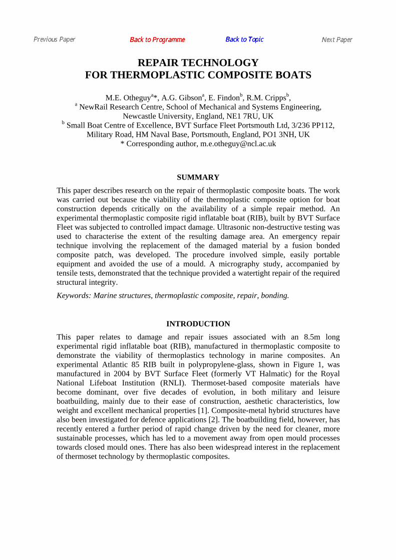
INTRODUCTION This paper relates to damage and repair issues associated with an 8.5m long experimental rigid inflatable boat (RIB), manufactured in thermoplastic composite to demonstrate the viability of thermoplastics technology in marine composites. An experimental Atlantic 85 RIB built in polypropylene-glass, shown in Figure 1, was manufactured in 2004 by BVT Surface Fleet (formerly VT Halmatic) for the Royal National Lifeboat Institution (RNLI). Thermoset-based composite materials have become dominant, over five decades of evolution, in both military and leisure boatbuilding, mainly due to their ease of construction, aesthetic characteristics, low weight and excellent mechanical properties [1]. Composite-metal hybrid structures have also been investigated for defence applications [2]. The boatbuilding field, however, has recently entered a further period of rapid change driven by the need for cleaner, more sustainable processes, which has led to a movement away from open mould processes towards closed mould ones. There has also been widespread interest in the replacement of thermoset technology by thermoplastic composites.
In addition to the need for clean processing, the interest in thermoplastic matrices has arisen due to the potential for recyclability and the possibility of greatly improved toughness [3-10]. The recyclability issue has only recently been practically examined [14] and it has been demonstrated that the hull structure of the thermoplastic RIB is indeed recyclable, by granulation and melt processing into a useful injection moulding material. The purpose of this study was to investigate repair, because the restoration of functionality following damage is a key requirement of any boat construction technology. Joining of thermoplastic composites could, in principle, be achieved by adhesive bonding, fusion bonding or mechanical fastening. Of these possibilities, fusion bonding, which is possible with thermoplastics but not thermosets, offers the greatest potential for a high strength, water-tight repair [11, 12].
Figure 1. Atlantic 85 RIB.
EXPERIMENTAL
Damage Event The main structural material used in the experimental Atlantic 85 was Twintex T PP 60 1485 woven polypropylene-glass commingled fabric, containing 60 wt.% glass in the form of 18µm diameter fibres. The boat internal structure was a sandwich construction of the Twintex fabric and DIAB Pro-balsa Standard core material. The sandwich laminates employed various thicknesses and numbers of plies, depending on function and position.
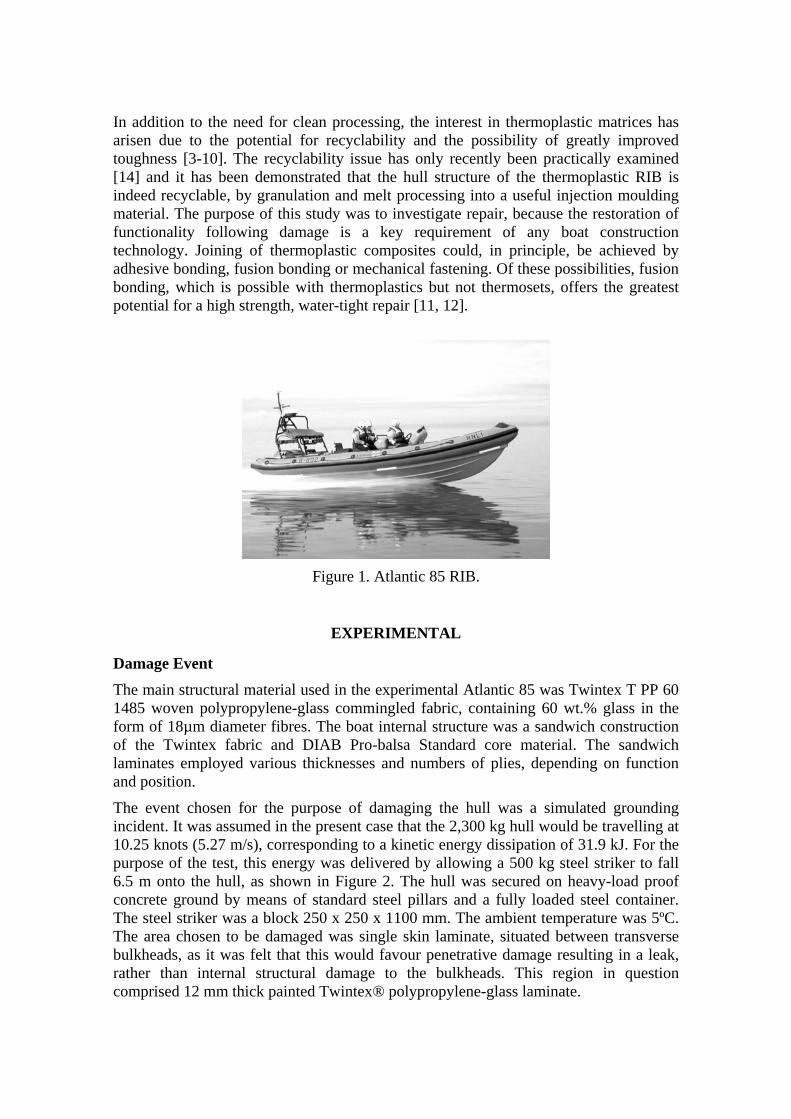
The event chosen for the purpose of damaging the hull was a simulated grounding incident. It was assumed in the present case that the 2,300 kg hull would be travelling at 10.25 knots (5.27 m/s), corresponding to a kinetic energy dissipation of 31.9 kJ. For the purpose of the test, this energy was delivered by allowing a 500 kg steel striker to fall 6.5 m onto the hull, as shown in Figure 2. The hull was secured on heavy-load proof concrete ground by means of standard steel pillars and a fully loaded steel container. The steel striker was a block 250 x 250 x 1100 mm. The ambient temperature was 5ºC. The area chosen to be damaged was single skin laminate, situated between transverse bulkheads, as it was felt that this would favour penetrative damage resulting in a leak, rather than internal structural damage to the bulkheads. This region in question comprised 12 mm thick painted Twintex® polypropylene-glass laminate.
If the impact had been near to a stiffener, the structural damage would have been transmitted through the structure to other areas in the hull. The stiffener or bulkhead would have absorbed a greater amount of energy, compared with the current study. As a result, a greater internal repair would have been needed, and a probably lesser hull shell damage would have been observed.
The impact velocity in the test was 11.25 m/s, a little over twice the envisaged speed of the craft. Although pure PP, being just above its glass transition, shows a brittle transition in this region [13], this does not occur in long glass fibre-based PP composites, since many other toughening mechanisms, involving interactions between the glass and the polymer, are present. With PP-glass, as with most other types of composite, the energy absorption in impact increases with testing velocity [15]. For a factor of two speed increase this effect would have been small, but it is conceded that the damage may have been slightly less extensive than for an impact at normal speed.
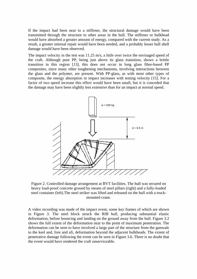
A video recording was made of the impact event, some key frames of which are shown in Figure 3. The steel block struck the RIB hull, producing substantial elastic deformation, before bouncing and landing on the ground away from the hull. Figure 3.2 shows the full extent of the deformation near to the point of maximum penetration. The deformation can be seen to have involved a large part of the structure from the gunwale to the keel and, fore and aft, deformation beyond the adjacent bulkheads. The extent of penetrative damage following the event can be seen in Figure 3.6. There is no doubt that the event would have rendered the craft unserviceable.
d = 6.5 m
w = 500 kg
Figure 2. Controlled damage arrangement at BVT facilities. The hull was secured on heavy load-proof concrete ground by means of steel pillars (right) and a fully-loaded steel container (left).The steel striker was lifted and released on the hull with a truck-
mounted crane.
3.1
3.2
3.3
3.4
3.5
3.6
Figure 3. Key frames from the video recording of the impact event.
Apart from the damaged perforation region itself, however, the remainder of the hull appears to have largely recovered its original shape. This shape recovery, despite the presence of significant damage, is a characteristic of composites which differs greatly from the behaviour of metal structures, where significant non-local plastic deformation is often observed.
While potentially advantageous from the repair viewpoint this shape recovery means that it is not possible to assess the true extent of damage following an impact solely from the appearance of the structure. This underlines the importance of using non-destructive evaluation (NDE) methods to determine the true extent of damage.
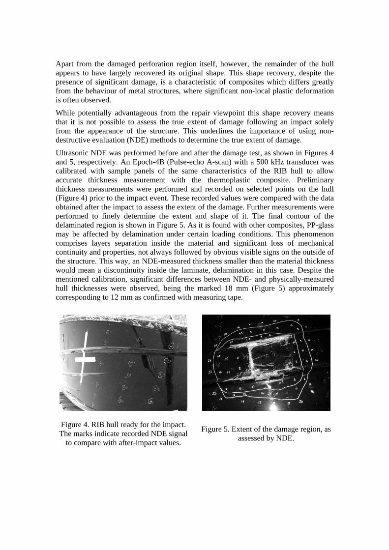
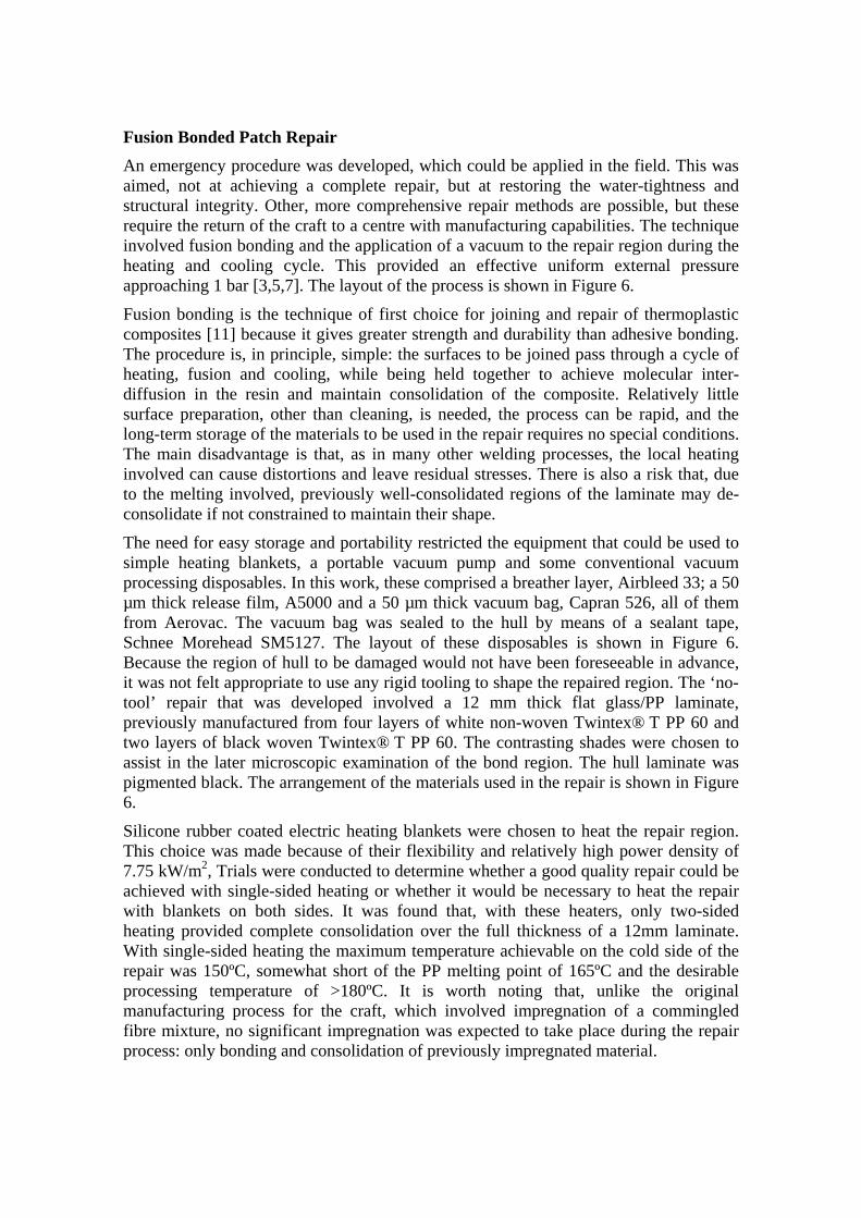
Ultrasonic NDE was performed before and after the damage test, as shown in Figures 4 and 5, respectively. An Epoch-4B (Pulse-echo A-scan) with a 500 kHz transducer was calibrated with sample panels of the same characteristics of the RIB hull to allow accurate thickness measurement with the thermoplastic composite. Preliminary thickness measurements were performed and recorded on selected points on the hull (Figure 4) prior to the impact event. These recorded values were compared with the data obtained after the impact to assess the extent of the damage. Further measurements were performed to finely determine the extent and shape of it. The final contour of the delaminated region is shown in Figure 5. As it is found with other composites, PP-glass may be affected by delamination under certain loading conditions. This phenomenon comprises layers separation inside the material and significant loss of mechanical continuity and properties, not always followed by obvious visible signs on the outside of the structure. This way, an NDE-measured thickness smaller than the material thickness would mean a discontinuity inside the laminate, delamination in this case. Despite the mentioned calibration, significant differences between NDE- and physically-measured hull thicknesses were observed, being the marked 18 mm (Figure 5) approximately corresponding to 12 mm as confirmed with measuring tape.
Figure 4. RIB hull ready for the impact. The marks indicate recorded NDE signal
to compare with after-impact values.
Figure 5. Extent of the damage region, as
assessed by NDE.
Fusion Bonded Patch Repair An emergency procedure was developed, which could be applied in the field. This was aimed, not at achieving a complete repair, but at restoring the water-tightness and structural integrity. Other, more comprehensive repair methods are possible, but these require the return of the craft to a centre with manufacturing capabilities. The technique involved fusion bonding and the application of a vacuum to the repair region during the heating and cooling cycle. This provided an effective uniform external pressure approaching 1 bar [3,5,7]. The layout of the process is shown in Figure 6.
Fusion bonding is the technique of first choice for joining and repair of thermoplastic composites [11] because it gives greater strength and durability than adhesive bonding. The procedure is, in principle, simple: the surfaces to be joined pass through a cycle of heating, fusion and cooling, while being held together to achieve molecular inter-diffusion in the resin and maintain consolidation of the composite. Relatively little surface preparation, other than cleaning, is needed, the process can be rapid, and the long-term storage of the materials to be used in the repair requires no special conditions. The main disadvantage is that, as in many other welding processes, the local heating involved can cause distortions and leave residual stresses. There is also a risk that, due to the melting involved, previously well-consolidated regions of the laminate may de-consolidate if not constrained to maintain their shape.
The need for easy storage and portability restricted the equipment that could be used to simple heating blankets, a portable vacuum pump and some conventional vacuum processing disposables. In this work, these comprised a breather layer, Airbleed 33; a 50 µm thick release film, A5000 and a 50 µm thick vacuum bag, Capran 526, all of them from Aerovac. The vacuum bag was sealed to the hull by means of a sealant tape, Schnee Morehead SM5127. The layout of these disposables is shown in Figure 6. Because the region of hull to be damaged would not have been foreseeable in advance, it was not felt appropriate to use any rigid tooling to shape the repaired region. The ‘no-tool’ repair that was developed involved a 12 mm thick flat glass/PP laminate, previously manufactured from four layers of white non-woven Twintex® T PP 60 and two layers of black woven Twintex® T PP 60. The contrasting shades were chosen to assist in the later microscopic examination of the bond region. The hull laminate was pigmented black. The arrangement of the materials used in the repair is shown in Figure 6.
Silicone rubber coated electric heating blankets were chosen to heat the repair region. This choice was made because of their flexibility and relatively high power density of 7.75 kW/m2, Trials were conducted to determine whether a good quality repair could be achieved with single-sided heating or whether it would be necessary to heat the repair with blankets on both sides. It was found that, with these heaters, only two-sided heating provided complete consolidation over the full thickness of a 12mm laminate. With single-sided heating the maximum temperature achievable on the cold side of the repair was 150ºC, somewhat short of the PP melting point of 165ºC and the desirable processing temperature of >180ºC. It is worth noting that, unlike the original manufacturing process for the craft, which involved impregnation of a commingled fibre mixture, no significant impregnation was expected to take place during the repair process: only bonding and consolidation of previously impregnated material.

Figure 6. Repair layout diagram. Further insulation was laid up on top of the vacuum
bags on both sides to prevent heat flowing outwards.
Prior to carrying out the fusion bonding process, damaged and delaminated material was removed from the hull, using the results of the NDE study as a guide. Material removal included some intact internal structure because of the space needed for disposables and vacuum arrangement on both sides of the panel. The reason for this is that the vacuum bag coverage must include both sides of the whole area to be repaired, plus the space required for the sealant tape, to provide the necessary pressure and air-removal from the repair joint. Inside the boat, the area to be covered is likely to intersect internal structure elements, as occurred in this work. Paint and dirt were sanded away and the edges were prepared with 35 mm long scarfs, giving a scarf angle of roughly 17º. Scarf lengths larger than this were not possible, due to space restrictions.
The flat panel was manually fitted in place. On both sides of it, layers of disposables and the heaters were applied and kept in place with spray adhesive. Although a one-stage process is achievable, in this work the fusion bonding of the panel joints was performed in four stages, corresponding to the four sides of the panel. In each processing stage, two heater blankets of the same size were used, one on the outside surface of the hull and the other on the inside. As a result, the intersections of the heated areas were processed twice. As the four sides of the panel were fusion bonded to the hull, the former matched the double curvature of the latter by means of the ambient pressure on the vacuum bag. The final curvature of the panel corresponded approximately to a 20 mm deflection over 500 mm long panel. Figures 7 and 8 show the final repair results.
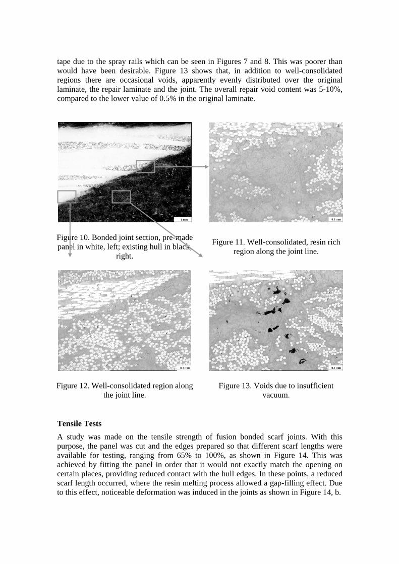
The processing time for the panel joints was 30 min at 185ºC. The heating and cooling periods on either side of the processing zone were around 30 min each, a typical temperature profile being shown in Figure 9.
The Atlantic 85 RIB includes spray rails to increase lift force and reduce hydrodynamic resistance. These comprise three longitudinal V-shaped thin, step-like members along
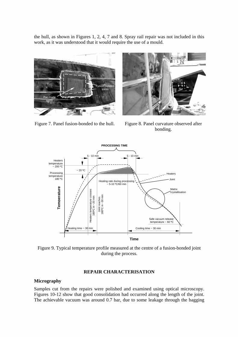
the hull, as shown in Figures 1, 2, 4, 7 and 8. Spray rail repair was not included in this work, as it was understood that it would require the use of a mould.
Figure 7. Panel fusion-bonded to the hull.
Figure 8. Panel curvature observed after
bonding.
Figure 9. Typical temperature profile measured at the centre of a fusion-bonded joint
during the process.
REPAIR CHARACTERISATION
Micrography Samples cut from the repairs were polished and examined using optical microscopy. Figures 10-12 show that good consolidation had occurred along the length of the joint. The achievable vacuum was around 0.7 bar, due to some leakage through the bagging
Pre-made panel
Fusion bonded joints
Heating rate during processing ~ 5-10 ºC/60 min
5 - 10 min
Heaters
Joint
Time
Tem
pera
ture
~ 20 ºC
Join
t rea
ches
18
0ºC
in ~
30 m
in
Heaters temperature
~ 200 ºC
Hea
ters
tem
pera
ture
cro
sses
18
0ºC
in ~
20 m
in
5 - 10 min
PROCESSING TIME
Safe vacuum release temperature ~ 60 ºC
Cooling time ~ 30 min Heating time ~ 30 min
Matrix crystallisation
Processing temperature
180 ºC
tape due to the spray rails which can be seen in Figures 7 and 8. This was poorer than would have been desirable. Figure 13 shows that, in addition to well-consolidated regions there are occasional voids, apparently evenly distributed over the original laminate, the repair laminate and the joint. The overall repair void content was 5-10%, compared to the lower value of 0.5% in the original laminate.
Figure 10. Bonded joint section, pre-made panel in white, left; existing hull in black,
right.
Figure 11. Well-consolidated, resin rich region along the joint line.
Figure 12. Well-consolidated region along the joint line.
Figure 13. Voids due to insufficient vacuum.
Tensile Tests
A study was made on the tensile strength of fusion bonded scarf joints. With this purpose, the panel was cut and the edges prepared so that different scarf lengths were available for testing, ranging from 65% to 100%, as shown in Figure 14. This was achieved by fitting the panel in order that it would not exactly match the opening on certain places, providing reduced contact with the hull edges. In these points, a reduced scarf length occurred, where the resin melting process allowed a gap-filling effect. Due to this effect, noticeable deformation was induced in the joints as shown in Figure 14, b.
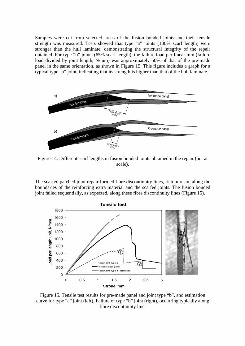
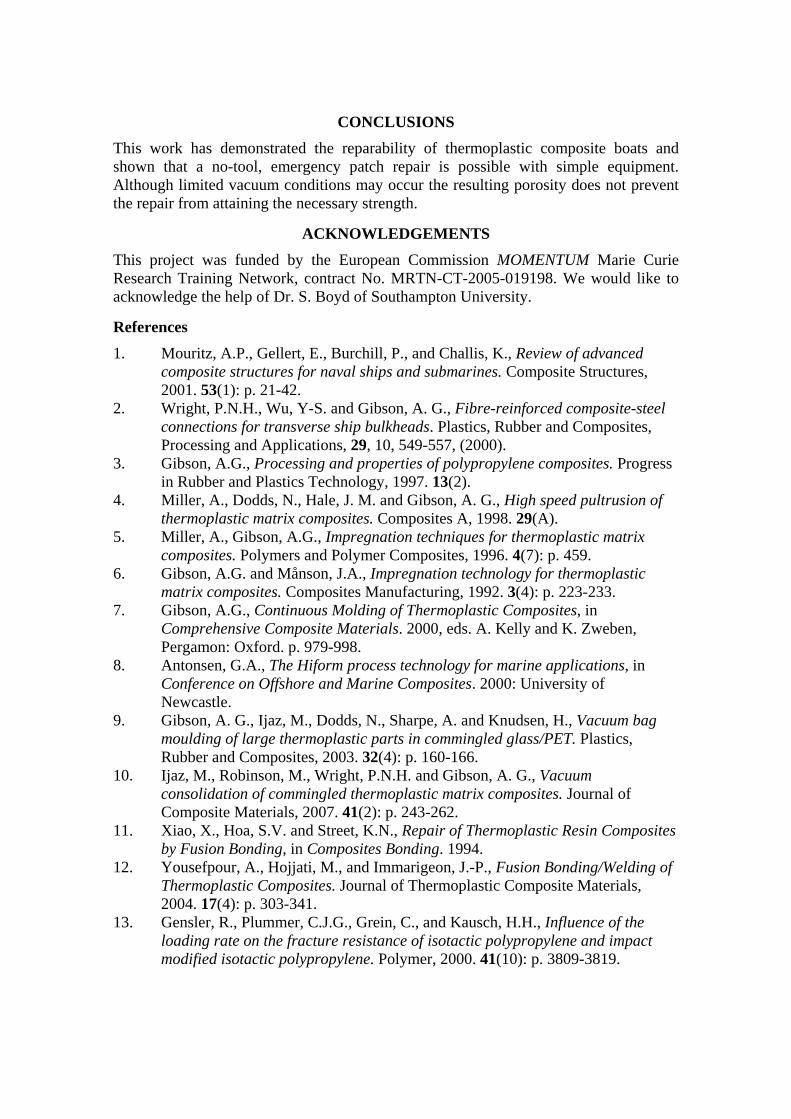
Samples were cut from selected areas of the fusion bonded joints and their tensile strength was measured. Tests showed that type “a” joints (100% scarf length) were stronger than the hull laminate, demonstrating the structural integrity of the repair obtained. For type “b” joints (65% scarf length), the failure load per linear mm (failure load divided by joint length, N/mm) was approximately 50% of that of the pre-made panel in the same orientation, as shown in Figure 15. This figure includes a graph for a typical type “a” joint, indicating that its strength is higher than that of the hull laminate.
Figure 14. Different scarf lengths in fusion bonded joints obtained in the repair (not at scale).
The scarfed patched joint repair formed fibre discontinuity lines, rich in resin, along the boundaries of the reinforcing extra material and the scarfed joints. The fusion bonded joint failed sequentially, as expected, along these fibre discontinuity lines (Figure 15).
Figure 15. Tensile test results for pre-made panel and joint type “b”, and estimation curve for type “a” joint (left). Failure of type “b” joint (right), occurring typically along
fibre discontinuity line.
CONCLUSIONS This work has demonstrated the reparability of thermoplastic composite boats and shown that a no-tool, emergency patch repair is possible with simple equipment. Although limited vacuum conditions may occur the resulting porosity does not prevent the repair from attaining the necessary strength.
ACKNOWLEDGEMENTS This project was funded by the European Commission MOMENTUM Marie Curie Research Training Network, contract No. MRTN-CT-2005-019198. We would like to acknowledge the help of Dr. S. Boyd of Southampton University.
References 1. Mouritz, A.P., Gellert, E., Burchill, P., and Challis, K., Review of advanced
composite structures for naval ships and submarines. Composite Structures, 2001. 53(1): p. 21-42.
2. Wright, P.N.H., Wu, Y-S. and Gibson, A. G., Fibre-reinforced composite-steel connections for transverse ship bulkheads. Plastics, Rubber and Composites, Processing and Applications, 29, 10, 549-557, (2000).
3. Gibson, A.G., Processing and properties of polypropylene composites. Progress in Rubber and Plastics Technology, 1997. 13(2).
4. Miller, A., Dodds, N., Hale, J. M. and Gibson, A. G., High speed pultrusion of thermoplastic matrix composites. Composites A, 1998. 29(A).
5. Miller, A., Gibson, A.G., Impregnation techniques for thermoplastic matrix composites. Polymers and Polymer Composites, 1996. 4(7): p. 459.
6. Gibson, A.G. and Månson, J.A., Impregnation technology for thermoplastic matrix composites. Composites Manufacturing, 1992. 3(4): p. 223-233.
7. Gibson, A.G., Continuous Molding of Thermoplastic Composites, in Comprehensive Composite Materials. 2000, eds. A. Kelly and K. Zweben, Pergamon: Oxford. p. 979-998.
8. Antonsen, G.A., The Hiform process technology for marine applications, in Conference on Offshore and Marine Composites. 2000: University of Newcastle.
9. Gibson, A. G., Ijaz, M., Dodds, N., Sharpe, A. and Knudsen, H., Vacuum bag moulding of large thermoplastic parts in commingled glass/PET. Plastics, Rubber and Composites, 2003. 32(4): p. 160-166.
10. Ijaz, M., Robinson, M., Wright, P.N.H. and Gibson, A. G., Vacuum consolidation of commingled thermoplastic matrix composites. Journal of Composite Materials, 2007. 41(2): p. 243-262.
11. Xiao, X., Hoa, S.V. and Street, K.N., Repair of Thermoplastic Resin Composites by Fusion Bonding, in Composites Bonding. 1994.
12. Yousefpour, A., Hojjati, M., and Immarigeon, J.-P., Fusion Bonding/Welding of Thermoplastic Composites. Journal of Thermoplastic Composite Materials, 2004. 17(4): p. 303-341.
13. Gensler, R., Plummer, C.J.G., Grein, C., and Kausch, H.H., Influence of the loading rate on the fracture resistance of isotactic polypropylene and impact modified isotactic polypropylene. Polymer, 2000. 41(10): p. 3809-3819.

14. Otheguy, M., Gibson, A.G., Findon, E., Cripps, R.M., Ochoa, A., Aguinaco, T., Towards fully recyclable craft, RINA Conference on Surveillance, Search and Rescue Craft 7, 2009.
15. Barré, S., Chotard, T. and Benzeggagh, M.L., Comparative study of strain rate effects on mechanical properties of glass fibre-reinforced thermoset matrix composites, Composites Part A 27 (12) (1996), pp. 1169–1181