n volume 8# 2 - world radio history
TRANSCRIPT

$4.95 ISSN 1042-198XUSPS 003-353
N VOLUME 8# 2SPRING 1995
RIC AIRCRAF1Vi, TVQi13 CM GASFET P WE4 A
ATV REPEATER COittovitoNEW 900 MHZ RULESNEW 2300 MHZ RULES
- MUCH !

HIGH FREQUENCY TECHNOLOGY INC.457 SANTA FE TRAILCARY, ILLINOIS 60013-1981Phone: (708) 639-4336
TX2500, TX1300, and TX930
Conservatively rated modular 1 Watt RF output stage.(0.5 Watt GaAs power amplifier on the TX2500)
Fully synthesized channels covering the entire amateur band:2390 to 2450MHz for the TX25001240 to 1300MHz for the TX1300902 to 928MHz for the TX930
Ultra linear, low phase noise VCO for unsurpassed videoquality never before seen in an amateur television transmitter.
Video frequency response from 10Hz to over 4MHz .
Built-in 5.8MHz high fidelity audio subcarrier generator.(internally adjustable from 4.5 to 6.5MHz)
Audio Frequency Response from 10Hz to 15kHz
RX2500, RX1300, and RX930
Low noise unconditionally stable MMIC front-end amplifier forsensitivity, stability and reliability.
2 -pole interdigital front-end preselector filter to reduce out ofband interference and overload.
6 -pole interdigital bandpass filter for great image rejection.
Optimized IF output filter provides spectacular rejection oflocal oscillator leakage and low dispersive effects.
AM amateur television reception as well as FM amateurtelevision reception when used with the IF70 IF/Demodulator.
Low phase noise local oscillator resulting in unrivaled onchannel sensitivity and adjacent channel interference rejection.
Greater than 80dB linear dynamic range with virtually nospurious outputs. (The signals at the IF output are reallyreceived and not generated within the downconverter.)
1F70
The only FM video -audio IF / Demodulator specificallydesigned for FM amateur television use.
Phase -locked loop video and audio demodulators "lock" ontransmitters with frequency drift and maintain the utmostpicture clarity.
Tune in audio subcarriers from 4.5 to 6.5MHz (4.5MHzceramic filters optional) with "Hi Fi" broadband response.
Tight IF selectivity provided by a 16MHz wide SurfaceAcoustical Wave (SAW) filter.
Optimal differential gain and phase response through the use oflinear phase filtering in both the IF and base band circuitry.
Call or write for complete specification sheets, ordering information and current pricing on these and other products.
Engineered and Manufactured Entirely in the U.S.A.

AMATEUR TELEVISION QUARTERLYVOLUME 8 # 2 SPRING 1995
Amateur Television Quarterly,(ISSN 1042-198X) is published four timesper year for S18 per year (USA) by HenryRuh, 5317 W 133rd Ave, Crown Point, IN46307 Second class postage paid at CrownPoint, IN 46307 and additional mailing of-fices. POSTMASTER: Send change of ad-dress to ATVQ, 3 N. Court St., CrownPoint, IN 46307
Subscriptions and submissionsshould be sent to Amateur Television Quar-terly (ATVQ) 3 N. Court St., Crown Point, IN46307. Packages should be sent to : AmateurTelevision Quarterly, (ATVQ) 3 N. Court St.,Crown Point, IN 46307. Telephone orders
may be placed using Visa or Mastercharge call219 662 63 96 Leave a night or weekend num-ber for any return calls. Orders may also besent via fax at 219 662 6991. Unless other-wise requested, subscriptions begin with thecurrent issue. Order forms for all ATVQ prod-ucts are in the centerfold. Subscription rates:$18 USA, $22 Canada, $29 elsewhere per year.A subscription is four issues.
Amateur Television Quarterly iscopyright 1995. All rights reserved. Non USpublications may reprint portions providedcredit is given in the title page and a copy ofthe publication is sent to ATVQ. Ham Clubsmay obtain blanket authority to reprint ATVQ
by submitting a written request with a copy ofthe club newsletter.
BACK ISSUES: are available exclusivelyfrom EFS Copy Service, 4011 ClearviewDr.,Cedar Falls, IA 50613. 319 266 7040. Acumulative index was published in Volume7 #1.
Publisher: Henry B. Ruh KB9F0Cartoons: Robert Beasley K6B.IHTranslations: Andrew Emmerson G8PTHRe -draft of drawings by Bill Parker W8DMRTypist, Debra Gillespie
Index NgW AT 04 AMATEURS NOW PRIMARY ON 2390-2417 MHZ7 STACKING ANTENNAS8 DAYTON SSTV INFORMATION9 STEREO ATV MODULATORS9 VIDEO ID9 SIMPLE IC OSCILLATOR10 H -P DIGITIZES CBS NETWORK11 UNMANNED AERIAL VEHICLES, R/C AIRCRAFT14 NEW EDITING SOFTWARE FOR HOME USE15 AUDIO SUBCARRIER OSCILLATOR AND MIC PREAMP16 SOLVING IN -BAND ATV DESENSE18 TOM RUTLAND SK, MIRAGE SOLD18 DAYTON ATV PARTY19 TRUE RF S METER20 HOUSTON ATV NEWS, CLUB IS BUILDING EQUIPMENT & ANTENNAS21 CHARLOTTE, NC AND SAVANNAH, GA NEWS22 THE W6ORGy NOTES28 BUILD A 13 CM GASFET POWER AMP USING PUFF CAD WARE42 A/B EDIT SOFTWARE FOR CUNSUMERS44 RF SHIELDING45 KB7BY ATV REPEATER CONTROLLER55 TWO BAND FM WLDEBAND FM RECEIVER56 ATVQ @ AOL. NEW 900 MHZ RULES60 SO YOU WANT TO BUILD A REPEATER: PART 461 BUILD YOUR OWN WHEEL ANTENNASDEADLINE FOR THE NEXT ISSUE IS JUNE 15TH, 1995
LAST ISSUEOur mailer would like to
appologize for delaying the last is-sue. They received it on March 3but didn't get it mailed until March21st.
With Sylvia and I both un-der going angioplasty heart surgerythe last issue was quickly put togetherto be done and to the printer before Iwent "under the knife." If nothingelse, the issue would be out while Iwas recovering. Or so was the plan.The printer got the job done, but theissue was misplaced at the mailingservice. I called when the mailboxwas empty too long and got themhumping. Because of the timing ofvarious events, a great effort by BillW8DMR arrived too late, so I haverepeated the articles he worked onin this issue with his improvedgraphics.
We are recovering and thekennel is full (over 50 dogs and 6cats!) as I write. I did not have timeto get a notice to DARA for the ATVparty, but we will meet as usual atthe Holiday INN, friday night. Stopby our booth, next to the bigKenwood sign!!
COVER PHOTO: KB8MDE Shawn Miller questions Bill Parker W8DMR about readings shown on afield strength meter. Shawn constructed the dual slot horizontal polarization 70 cm 017111i ATV antenna
for use with the Columbuis, OH ATV repeater
ATVQ, SPRING 1995 3

AMATEURS ARE PRIMARY ON2390 MHZ TO 2417 MHZ
One of the provisions of the Omnibus ReconciliationAct passed by congress recently was to reallocate 50MHz of spectrum immediately from government use tocivilian use. This included 2390 Mi-lz to 2400 MHzand 2402 MHz to 2417 MHz. Many Ham operatorstold me that there is nothing that can be done and wemight as well give up. I was not going to give this upwithout a fight. Our Amateur Television Network(ATN) uses links on 2417 MHz. Too much time andmoney was spent interconnecting our system...so the
fight was on!First was the "Notice of Inquiry" by the NTIA (they
regulate federal government frequencies) last fall.With the help from the ARRL in providing me a copyof this document, were spent writing comments.ATN's comments informed the NTIA of our usage andthat from other groups in our area (SCRRBA). Ourfrequency coordinator provided me with data. Theyalso wrote very detailed comments to the NTIA. Ourbest ally in this spectrum was the part 15
manufacturers and users (part 15 band 2400 MHz to2483 MI-Iz). ATN indicated that the part 15 usage wascommercial use and met the requirements of theReconciliation Act.
We also pointed out the public safety use of ATV andthe value of linked repeaters. ARRL, AMSAT andabout five other amateur groups submitted very goodcomments. Also, a few individual amateurs also hadsubmitted comments. I think this is good that severalcommenting parties submitted, but we should have hadhundreds! I asked several amateurs to write a responseand the usual answer was, I don't have time, I don'toperate on 2.4 Gliz or the ARRL will fight, so I don'thave to. I want to express my thoughts on this. If youwant to keep your Amateur frequencies, take the time.It is not that difficult!
The ARRL can help you with documentation whenwe have to fight again. By the way, later this year2300 MHz to 2310 MHz is on the action block fromthe NTIA so let's see hundreds of comments this time.The commercial manufacturers are numerous and theywill comment, spectrum is at an all time premium so wehave to fight for it. We won this last fight, so let's keepthe pressure on to keep all of our spectrum!
Well, now that I have gotten off my horse, let'scontinue. For every comment period there is response
to the comments period. ATN was there too and nowwe had a chance to see the comments of thecommercial and amateur parties. This is where thereading begins, take notes (note commenting party,page, paragraph and item of discussion). You willcomment for or against this in your response letter.
The FCC next had a Notice of Inquire, followed bya Notice of Proposed Rule Making. Both hadcomments and response comment periods. I will notgo into the details, but the formats were about thesame as the NTIA inquiry we discussed earlier. Thefollowing items are required to properly comment orrespond.1. Indicate the name of the government organization(FCC or NTIA) with address.2. Indicate the inquire or proposed rule makingdocument number.3. Give your name or organization's name withaddress.4. Date and sign your document.5. Please send it in before the deadline. (Sometimesthey give 30 days to respond.)6. Send the original plus 9 copies so each FCCchairman will have a copy. (Only the original and 4copies are required to file.)7. Send your documents overnight or two day mailand have it registered and signed by the receivingparty.8. Please make your responses factual and leave outthe cry baby comments. In short, a professionallooking document will go a lot further thancomplaints.9. I am not a lawyer or professional document writer,so if I can do it, you can too! One or two eveningsshould be enough time to write a response orcomment. Enclosed is a sample of a responsedocument.
I hope this will help you for the next fight to keep ourfrequencies. If you need help or have questions, I canbe reached at the below address.
Mike Collis, WA6SVTPO Box 1594
Crestline, CA 92325Please give me your phone number too so I canrespond quickly.
4 ATVQ, SPRING 1995

June 7, 1994
Amateur Television NetworkMike CollisPO Box 1594Crestline, CA 92325
Mr. Caton, Acting SecretaryOffice of the SecretaryFederal Communications CommissionWashington, DC 20554
2400 MHz Comments
In the matter of:Allocation of Spectrum Below }ET Docket No. 94-325 Ghz Transferred from Federal Government Use ) Notice of InquiryAmateur Television Network would like to comment and reply to the eight questionscontained within this inquiry. First, I would like to give a brief description ofour network. Our group currently has eight open Amateur Television Repeater (Relay)stations that are in use for emergency operation as well as for the enjoyment ofthe users. The repeaters used 434 Mhz AM television inputs and our Santiago PeakRepeater also has 2441.5 Mhz FM (terrestrial standards) television input. We planto include this input to the rest of the repeaters should we be allowed to stay inthe 2.4 Ghz band. Our outputs are on the 1.2 Ghz and .915 Ghz band using VSR AMtelevision to best utilize the available spectrum. We also use 2417.5 Mhz FM asa video link channel on several of our repeaters, our longest link is 174 miles fromBlue Ridge Mt. near Wrightwood, CA to Mt. Potosi, Nevada near Las Vegas.A) The spectrum does not have limited potential for promoting economicgrowth in three areas as follows:
1) The appliance industry has made millions of dollars manufacturingmicrowave ovens using spectrum in the ISM band around 2.45 Ghz.Competition is strong among the manufacturers.2) Part 15 devices, many using spread spectrum and other high tech
modes, are selling well in southern California. Many other manufacturers havedesigns in for type acceptance or on the drawing board. Competition should be goodas long as the band does not get spoiled as did the 900 Mhz band in use by part 90devices.
3) As more amateurs are using the 2.3 to 2.4 Ghz band, more jobs willbe created to supply and manufacture equipment. I have seen four new manufacturersstart up with microwave equipment on the 2.4 Ghz band within the last two years.The band is getting most of the new users from the Amateur Television and AmateurSatellite community. I do want to stress that this is new equipment sales, notconverting old surplus part 94 microwave equipment. Existing commercialmanufacturers are benefiting from amateur radio sales such as Conifer Corporation(ITFS & Wireless manufacture) they are getting many orders for their dish antennas,down converters and bandpass filters for use by the Amateurs.The most appropriate use of the band and services would be as follows:
1) Amateur Radio has first priority in the 2.3 to 2.4 Ghz band toprovide public service capability as well as an overflow military spectrum to beused during wartime conditions.
2) Continue to allow ISM operation in the 2402 to 2450 Mhz area. Allother users to accept any interference caused by ISM operation.
3) Part 15 devices to have last priority in the band with the powerkept limited to its current level as to minimize interference to amateur operations.Part 15, 1 watt spread links (dish antennas) must coordinate with the Amateur Radiolocal coordinator as to avoid interference to existing Amateur links while using2402 to 2450 Mhz.
ATVQ, SPRING 1995 5

2400 MHz Comments
B) 2390 to 2400 Mhz should be used as additional down link from AmateurSatellite service as well as medium bandwidth links to pair with 2300 to 2310 Mhzexcluding 2303 to 2305 (weak signal window).
This should protect the adjacent spectrum concerns of the NTIA. Competitionshould grow as more amateurs buy equipment for the band. Some limitedcommercial use may be possible in a case -by -case basis. As an alternative,Amateur Television links can use any 20 Mhz wide channel (two minimum arerequired) of spectrum from 1300-2500 Mhz.
C) No, the FCC should limit the use to Amateur part 15 and ISM services. 2400to 2402 is not sufficient to protect against interference from high power commercialtransmitters to Amateur Satellite reception due to the weak signals involved.D) No, many populated areas of the country have established links of the FDM,Digital and Video messaging. With part 15 as well as ISM operations currently sharingthe 2.4 to 2.45 Ghz, this is meeting the requirements of the reallocation for thisband!
E) No, in the list of filed comments on the NTIA report #035 from Motorola INC."believes that the existing and anticipated noise levels in the 2402-2417 Mhz bandfrom existing and planned ISM and commercial unlicensed Part 15 devices already usingthe band render this spectrum practically unusable in metropolitan areas for highquality, wide area land mobile communications services." GTE (#037) also has concernsthat the 2402-2417 Mhz will be hampered by amateur, Part 15, and noise from ISMdevices. Any new service in this band will create the same problems that plague the902-928 Mhz band. This many of the jobs created by thepart 15 and amateur manufacturers.F) This is one of the best areas for the Amateur Radio community to help thePublic Safety workers to communicate by use of the Amateur Television Repeaters duringdisasters. A helicopter can flyover an effected area and the command center personnelcan see first hand the disaster damage and save several minutes of air time that wouldotherwise be needed to describe the disaster seen. Also, linked voice and datarepeaters can help relieve congestion in ordering medicine and other emergencysupplies during disasters. Health and welfare messages can be relayed as was the caseduring the Northridge (LA) earthquake last winter using a 440 Mhz voice repeaternetwork linked on 2.3 and 2.4 Ghz.G) The 1390-1400 Mhz paired with the 1427-1432 Mhz band or a 1 Mhz portion offof each band would work the best for this service to relieve biomedical telemetryespecially in the larger metropolitan areas. The 2390-2400 Mhz does not provideadequate separation for duplex operation. 2402-2417 Mhz is unsafe due to part 15devices and ISM noise. The 4660-4685 Mhz band does not provide adequate separationfor duplex operation as well as poor penetration of buildings for biomedicalcommunication.H) This may be a worthwhile decision so time can be spent to study the resultsof some of the reallocated spectrum.Thank you for your time in consideration of our comments.
Sincerely,
For the Amateur Television NetworkMichael V. Collis
6 ATVQ, SPRING 1995

Designed specifically for amateur television in the 70cm band...
FL407 INTERDIGITAL FILTER7 -Pole Interdigital VestigialSideband Filter for Frequency Rangesof 420 MHz to 440 MHz
The 6 MHz nominal bandwidthand low loss design are perfectfor transmitter or receiver use.Two filters can be used forrepeater applications.
Heavy duty construction insuresstable operation and long life.
Ordering Information: The FL407 may be orderedon any frequency between 420 and 440 MHz. Pleasespecify video carrier frequency when ordering.
Dimensions HWD:2 1/8" x 8 13/16" x 20 5/8"
ismInternational Crystal Manufacturing Co., Inc.
P.O. BOX 26330 701 W. SHERIDAN OKLAHOMA CITY, OK 73126-0330 (405) 236-3741 FAX (405) 235-1904
STACKING ANTENNAS\Over the years ATVQ has received many letters asking
about stacking antennas and related questions. There is confu-sion because the manufacturers and various antenna books haveconflicting information. In general, antennas are stacked side byside (horizontally) or vertically (above each other) at distances ofhalf wavelengths or full wavelengths. Small antennas stack atdifferent distances than large antennas because of aperature.Phasing cables can be cut to equal but random lengths, althoughmost writings indicate equal lengths at multiples of a half wave-length. The purpose being to repeat the antenna impedance at thejunction point to minimize any effects of antenna mismatch, sincethe VSWR repeats exact voltage/current relationships every halfwavelength.
Mike Staal of M2 answers the questions this way:
QUESTION: Why do some antennas stack at onewavelength and others two wavelengthspacings?
I think you are referring to the distance between 2, 4or 8 given yagis of the same model; i.e., -8 x 2M18XXX. Thestacking distance is determined by the aperture of the singleantenna. As gain goes up, aperture increases. When stackedproperly for near peak gain and reasonable side lobes, the
apertures just overlap. 1 wave length opening would only be rightfor a small, low gain yagi like our 2M7.QUESTION: In order to repeat the antennaimpedance, multiples of a wavelength orhalfwavelength are required. What is the WLfor common frequencies in 9913 coax?
1 WL of 9913 is about 68.8 @ 144 (using .84 vf);about 23.275 @ 432. You might heavily consider the new TimesLMR 400 (same size as 9913) because it's better for weather(closed cell foam), lower loss, and weighs only 7 lb./100 ft. (9913is 18 lb/100 ft.) Same connectors fit. We've convertedcompletely. Price from distr. is $.50 @ 500 ft. roll. In responseto your statement, "I used a random but equal length last time...isthere any other reason?" It is good engineering practice but notcritical.QUESTION: Can you mount H and V elementsspaced 1/4 wavelength apart on the same boom
for circular polarizatrion?Yes, many people are asking us to do that; we will soon be
offering a polarity diversity switcher for receiving only producingH, V, Right Orthagonal (45 deg. tilt), left orthagonal, RHC &LHC. Regards, Mike, Myrna 88/73
ATVQ, SPRING 1995 7

Crystals for manapplicationsFor over 40 years, ICM hasmanufactured the finest inquartz crystals for everyconceivable purpose.
A wide selection of holdersare available to fit most anyrequirement. Our computerdatabase contains crystalparameters for thousands ofequipment types.
Need crystals forcommunications, telemetry,industrial, or scientificapplications? Let ICM'ssales department assist youto determine which type ofcrystal is best for you.
Can we solve yourcrystal problem?For special purposecrystals, special holders,special sizes, call our crystalsales department. We willbe pleased to providerecommended data.
International CrystalManufacturing Co., Inc.
PO Box 26330. 701 W Sheridan.Oklahoma City. OK 73126-0330Phone (405) 236-3741Telex 747-147Facsimile (4051 235-1904
DAYTON 95 SSTV MEETINGS12:00 - 2:15 SLOW SCAN TV
Moderator: Dr. Don C. Miller, W9NTPSpeakers: "The Latest Developments in SSTV Scan Converters and Other SSTV Hardware fromJapan." Presented by Izumi Soma, KH6JDU/JA1KZS"
Robot Helper, Version 2.1, (from VE3EC), A Computer SSTV Control Program, alsoRobot 1200C Robograb and Superscan 2001 Paragrab, A Real Time Video Capture Mod.from G7IZW,GPKH). Presented by Tom Hibben, KB9MC.All you ever wanted to know about JVFAX (from DKJV). Presented by Elwood McCollum,KQ4XZ..
Friday Evenings
7:30 - SSTV Get Together, Holiday Inn North, 2301 Wagoner Ford Road.
Tom Hibben, KB9MC, and Don C. Miller, W9NTP will host. Several simultaneously operating SSTVsystems will be on display for demonstration or audience participation the entire evening. Many experts willbe present to answer your personal questions on new SSTV systems and improvements. IVCA will againoperate Booth 212 at the arena with several SSTV systems operating during the entire convention.
8 ATVQ, SPRING 1995

ATVQ TECH -NOTEBob, KC6GAG
A logic IC can serve as an Audio Subcarrier Generator, includingan audio amplifier for the microphone. A line inverter, 74HC04provides all the necessary amplifiers.
OutputFrequency
Diagram re -drawn by Bill ParkerW8DMR
OMIK Annual ConventionFrom: [email protected] (Sara E. Jackson)The 43rd annual convention of the Omik Electronics Com-munications Association, Inc. will be held at the RichmondOmni Hotel in Richmond, Va. on July 12-15, 1995. TechSessions, FCC Testing, Scholarship Awards, Tours, Enter-tainment and much more. Contact WQ6I at POB 639 -Claremont, Ca. 91711 for registration
STEREO VIDEO MODULATORS
Single output stereo modulators deliver true MTS with dbx.Digital tuning. Available outputs: UHF chan 14-60. Hyperbandcable chan. 37-64, or Ultraband cable chan. 65-111.HCC-2011U Stereo Video Modulator/UHF Output ONLY $599HCC-2011HB Stereo Video Modulator/UB Output ONLY $599HCC-2011UB Stereo Video Modulator/UB Output ONLY $599Saw the above ad and thought some folks may like to obtain a unitdirectly on their ATV frequency since these tune the cable channels57-60 which are ATV frequencies. Have a high class repeaterexciter with stereo audio! 73 Henry
1 -800 -CONTROL
ATV HELP NEEDED FORSPECIAL OLYMPICS
Battles, Brian, WSJOFE!
As Amateur Radio Liaison to the 1995 Special Olym-pics World Summer Games in Connecticut this July 1-9, I'vebeen trying to help arrange to accommodate the SO officials'request for ATV coverage of the Sailing events. I'm beingassisted by active local ATVer Fran Miele, N1GAU(Fran.Mele@circellarcom). The SO officials ideally wouldlike to have ATV transmissions from 2 or 3 judges' boats inNew Haven Harbor, sending back live color TV to a receiv-ing station on shore, where they can then display the video ona couple of large monitors, and record it on a VCR.
Fran advises me that several local ATVers have ex-pressed the following concerns: (A) Some scheduling diffi-culties because of their daytime jobs (B) Concern for usingtheir equipment around salt water (C) Reluctance of indi-viduals to go through the process of setting up, testing andoperating their gear each day, only to tear it down at night...andthen have other volunteers step in to do the same thing allover again the next day...for several days!
The immediate solution that occurs to me is to obtain2 or 3 transmitters, a receiver and antennas that can be set up
for the duration of the Games and operated byany ATVers (or other trained hams) who are able to get to thesite each day. Fran and his colleagues feel that 10-watt trans-mitters and omnidirectional antennas will probably be neededto send the signals to the receiving station via simplex or theNew Haven ATV repeater. Unfortunately, I haven't been ableto find a source for a donation/loan of such equipment anddon't know of any means of obtaining funds to purchase thenecessary equipment (the Special Olympics claims it has nobudget available for such a project).
If you have an suggestions or know of anyone whomight be able to offer ideas/solutions, please contact me. We'dgreatly appreciate any assistance, and it will certainly be amajor "feather in the cap" for Amateur Radio if we can puttogether an impressive ATV operation, especially for this event,which is expected to be attended by major celebrities, digni-taries and more than 700,000 spectators, with more than 1500international media representatives on hand! Anyhow, anyhelp or advice you can offer is appreciated! Thanks and very73, Brian Battles, WS10, New Britain, CT USA, AmateurRadio Liaison, 1995 Special Olympics World Games, 203-666-1541 (work), 203-827-9956 (home), 203-665-7531 (fax)E-mail: [email protected] (office), [email protected] (home)Packet:WS [email protected] (AX.25)[email protected] org TCP/IP)
ATVQ, SPRING 1995 9

HP ANNOUNCES TV NETWORK TO INSTALLBROADCAST VIDEO SERVER;
CBS BEGINS CONVERSION TO DIGITAL BROADCASTING
Palo Alto, Calif., Aug. 30 -- Hewlett-PackardCompany today announces that CBS Inc. plans tointroduce digital video servers to television broadcastingwith CBS' first installation of the HP broadcast videoserver. The server initially will replace the traditionalvideotape robotics carousel, called a cart system, whichmanages a library of cartridges and is programmed toplay back commercials, promotional spots and othershort form preproduced programming.
By making the commitment to digital broadcast-ing, CBS, one of the original pioneers in television,continues to play a leadership role in the industry bypioneering the digital television age.
CBS was the first network to set up a task forcefor digital broadcasting, said Bishop Cheen, senioranalyst with Paul Kagan Associates, a leading mediaresearch firm, Cannel, Calif. The concept of a videobroadcast server, like HP's, is the first bridge in bringingbroadcasting into the digital age in a compelling costeffective way. It also does it in a way that is completelycompatible with 170 million TV sets in use today.
CBS plans to install the server at WCIX-TV, theCBS owned television station in Miami. Miami is the15th largest television market in the United States. TheHP broadcast video server will work alongside WCIX'sexisting environment, replacing its videotape recordersystem.
We have made a significant commitment toprovide digital based products to the video communica-tion industry, said James D. Olson, general manager ofHP's Video Communications Division. HP's alliancewith CBS is the first wave in the transition of digitalbroadcasting for the worldwide television industry. HPrecently announced sales of its HP broadcast video serverto CBS affiliated station KOLD-TV in Tucson, Ariz.,and the Radio Television Luxembourg network RTS2based in Munich, Germany.
The HP broadcast video server providesexpandable disk based on-line storage from six hours to51 hours of programming and three video outputchannels for users flexibility and reliability. The serverincludes software redundancy, dual standby powersupplies and failure -proof disk storage modules with500,000 hour mean time between failures reliability.
Hewlett-Packard Company took a great deal ofcare and attention by investing in meeting the critical pathrequirements of broadcasting, said Crag Birkmaier, a
video industry analyst, based in Gainesville, Fla. The HPbroadcast video server is bulletproof.
The HP video broadcast server uses MotionPicture Experts Group (MPEG) compression to storebroadcast quality video.
CBS recognizes the need to look to the future oftelevision by building the infrastructure for total digitalbroadcasting now, said Robert Seidel, vice president ofengineering for CBS. Our vision is to combinecommunications and networking technology to make ouroperation more reliable and efficient. MPEG compressionwas a desirable feature in the HP broadcast video server.
MPEG is the emerging de facto transmissionstandard for the content distribution format, saidBirkmaier. The economics of storing information by usingPEG is a factor of 3 -to -1 greater than an intraframecompression system such as JPEG.
In addition, WCIX will be using HP's admanagement system software, which provides a totalsolution for automated scheduling playback of advertise-ments and programs to air. The software controls all stepsof the commercial broadcasting process, includingscheduling play lists, recording material into digitalformat, managing information in the broadcast videoserver database, playing advertisements on -air andcompiling the as -run lists for advertising agencies.
Hewlett-Packard is an international manufacturerof measurement and computation products and systemsrecognized for excellence in quality and support. Thecompany's products and services are used in industry,business, engineering, consumer electronics, videocommunications, broadcasting, medicine and education inapproximately 110 countries. HP has 97,900 employeesand had revenues of $20.3 billion in its 1993 fiscal year.
Note to the Editor: Sales information may beobtain by calling 1-800-752-0900. Please do not useeditor contact or corporate telephone numbers for salesinformation.
Information in this release applies specifically toproducts available in the United States. Productavailability and specifications may very in non-U.S.markets.
Contact: Hewlett-Packard Company, John L.Minck, 408-553-3891 -- CBS Television, Robert Seidel,212-975-1785 -- Copithorne & Bellows, PR, MarcyDockery, 408-988-2100.
10 ATVQ, SPRING 1995

UAV WITH ATV CONTINUED DEVELOPMENTRon Berkman KA9CAP
1003 S. Philo Rd. Urbana, IL 61801
4---- I /2 WAVEVERTICALANTENNA
AIRBORNE COMPONENT PLACEMENTThis is a continuation of my original article
which appeared in ATVQ Vol. 6 #1 (Jan., Feb., March,1993) and described how I first acquired live video froma Radio Controlled Model Aircraft (UAV -UnmannedAerial Vehicle).
Since the article appeared, I have acquired aSupercircuits PC -7 color camera to replace the originalB/W camera, installed it in a brass case with suitabledecoupling and, due to its larger size, have mounted it onthe underside of the fuselage near the center of gravity.(See Figure 1.)
Based on flights occurring on May 21, 1994, Idecided that I had insufficient transmitter power onboard the aircraft as I experienced a large number ofpicture dropouts and general messiness of the picturesfrom the plane, particularly at high altitudes. I ordereda TXA5-RC transmitter board from P.C. Electronicsand requested that it be set on maximum power output of1.5 watts. The previous board was rated at 80 MW.Because the dimensions of the new board matched thatof the old board, I was able to mount the new boarddirectly in the case already constructed with nomodifications.
The next problem encountered with thehigher ATV transmitter power was interferencewith the Radio Control System which operates at53.5 MHz AM. The receiver (ACE R/C SilverSeven) was unaffected by the 80 MW transmitter,but now could see the servos "jittering" wheneverthe ATV transmitter was activated with 1.5Woutput. This meant it would be necessary toconstruct a shielding case for the R/C receiver, (seeFigure 2), and provide for decoupling of all powerand signal wires from the receiver using 470pf feedthru capacitors. I also added ferrite beads to thewires running to each of the servos. As a final touch,following P.C. Electronics instructions and usingthe parts they sent with the new board, I built the lowpass filter consisting of a .22uH inductor and two33pf capacitors inside the receiver case.
I neglected to retune the receiver before thefirst flight and lost control of the plane about 50 ft.down the runway which resulted in a crash. Thelesson learned here is that when you place a receivernormally in a plastic case inside a metal case and
ATVQ, SPRING 1995 11

UAV WITH ATV CONTINUED DEVELOPMENT
add parts to the antenna system, youMUST RETUNE the receiver! I havenow retuned the receiver and rebuiltthe plane and conducted range checksto verify control with theATV system turned on. The R/Creceiver now appears to be operatingnominally.
On July 18, 1994, I flew theplane with the following resultsshown in pictorial form:
With the system nowoperating in good form, I cannow concentrate on buildinga larger and more powerfulaircraft to carry the addi-tional load which will beimposed by the next phase ofdevelopment.
I have acquired acomputer and associatedequipment to add videotelemetry to the downlinkpicture. Plans call forairspeed, altitude and com-pass heading to be shown realtime on the video along withbattery voltage readings andcall sign every ten minutes.This video overlay system isavailable from High Technol-ogy Flight. When this equip-ment is finally mated with itssensors, a bigger battery packand made operational, I willwrite about its performance in afuture article.
As you can see, I amstill having fun with ATV andas an aside, we did some testing
to see if my airborne ATV canbring up the KA9SZX ATVrepeater in Champaign, IL withthe higher power I am nowrunning. The distance involvedis about 10 miles as the crowflies. We found that the higherpower would still not bring upthe ATV repeater, however,KA9SZX at his home station,was able to view the video direct.The picture quality was poor but
occasionally it"popped in" whenI was banking theaircraft and caus-ing the verticalantenna to go hori-zontal. Mark(KA9SZX) feltthat if I had ahorizontally polar-ized antenna onthe aircraft, hewould get an ex-cellent picture di-rect, and since theATV repeater ishorizontally polar-ized, I wouldlikely bring upthe repeater. Ihave orderedLittle Wheelsfrom Olde An-tenna Labs forinstallation on theaircraft and onthe groundmount. Morelater!
12 ATVQ, SPRING 1995

SHEET BRASSLAYOUT
. 2 "
2
ADD SUITABLE FEED THRUCAPACITORS FOR EACH SERVOAND + INPUT VOLTAGE.
CASE IS GROUND
ADD GROMMETFOR RX ANTENNA
FINISHED .010 BRASS CASE FORSHIELDING ACE R/C SILVER SEVENR/C RECEIVER.
ATVQ, SPRING 1995 13

GO -VIDEO TO OFFER VIDEO EDITING SOFTWAREFOR ITS NEW PC -COMPATIBLE
8mm/VHS DUAL -DECK VCR'SScottsdale, Ariz., Aug. 2, 1994 - Go -Video
(AMEX: VCR) today announced it has reached an OEMagreement with Gold Disk, Inc. that will enable Go -Videoto provide a video editing software package to users ofGo -Video's new PC -Compatible 8mm/VHS Dual -DeckVCR' s .
Under the agreement, Gold Disk is providing aspecial customized version of its award -winning VideoDirector software. The new software will be optimized towork with the Go -Video 8mm/VHS Dual -Deck VCR andwill take advantage of the unique capabilities of the Dual -Deck VCR.
The software, which will be marketed by Go -Video under the trade name "Dual -Deck Director," willenable users to control the Dual -Deck VCR from theircomputer and perform professional -style editing. Go -
Video's PC -Compatible Dual -Deck VCR (Model 8050)and the software package will begin shipping inNovember. The software will be available in Windowsand Macintosh versions. An additional model of Go -Video's PC -Compatible VCR's, Model 8080, isscheduled to ship in 1995.
Roger Hackett, president and chief executiveofficer of Go -Video, said, "by combining computertechnology with our new 8mm/VHS Dual -Deck VCR weare adding extraordinary value to our products andopening new markets for them. This combination ofproducts is an example of the merging of computers andconsumer electronics that is clearly the wave of the future.This product and others to follow show that Go -Video isuniquely positioned to take advantage of these newopportunities."
Hackett continued, "Dual -Deck Director allowsus to offer a unique product to consumers who want to bemore interactive with their electronic equipment. Thisproduct will appeal to a wide range of consumers andprofessionals and should be especially interesting toparents and teachers who want to provide youngsters withan educational and entertaining hands-on experience."
The software will be "bundled" with Go -Video'sexclusive edit controller which is a hardwarecommunications link between the computer and the VCR.
"The Dual -Deck Director, combined with Go -Video's new VCR, is a complete home or small officevideo editing solution that is easy to use and mostimportantly, affordable," said Neil Snyder, vice presidentof marketing for Santa Clara based Gold Disk. "In thepast, frame -by -frame videotape editing and adding funtitles and graphics was only available to those willing to
spend thousands of dollars on professional editingequipment. This technology bundle gives every 8mmcamcorder user access to creativity and fun at a veryaffordable price."
The suggested retail price for the software/editcontroller combination is $299.99. It will be sold throughGo -Video's consumer electronics retail channels,computer dealers and special markets.
VIDEO TAPE EDITING MADE EASYWITH THE DUAL -DECK DIRECTORDual -Deck Director is an analog videotape editor
allowing Go -Video users to utilize their Windows PC orMacintosh computers to control their Go -Video 8mm/VHS Dual -Deck VCR. Users can select scenes from anynumber of 8mm tapes, arrange those scenes in any order,then automatically create a new tape by copying thoseselected scenes from 8mm video cassettes to VHS tapesfor easy distribution to family members, employees orfriends. Depending on the computer hardwareconfiguration, Dual -Deck Director provides users withthe ability to add sounds, titles, animations, graphics,wipes, transitions, and music to their newly created tapes.
Go Video is the designer, developer and patentholder of the first Duel -Deck VCR sold in the UnitedStates and the only videocassette recorders that can copyany VHS videotape. The Go -Video Dual -Deck VCR'sare sold through prominent retail outlets nationwide andare featured in numerous popular catalogs. A leader inVCR technology, Go -Video is continuing its tradition ofinnovation through continuous research and develop-ment, and a strategic relationships with other leading edgecompanies.
Gold Disk, Inc., founded in 1984, is a leadingdeveloper of multimedia technologies and publishers ofnext generation presentation tools and applications forWindows based PC and Macintosh computer users.
Other Gold Disk products include: Astound forMacintosh and Windows, Video Director for Windowsand Macintosh, Professional Draw, Animation WorksInteractive, Animation Works for Windows andMacintosh and ScreenCraze II. Inherent in all Gold Diskproducts is an easy -to -use point and click graphicalinterface providing a consistent look and feel for users.Gold Disk is privately held and is based in Santa Clara,Calif., with international offices in Canada and the UnitedKingdom.
Contact: Edward J. Brachocki, V.P. of Go -Video, 602-998-3400; or Michaela Brehm, corporatecommunications, Gold Disk, 408-982-0200.
14 ATVQ, SPRING 1995

ATV TECH NOTE: FROM N6REAUDIO SUBCARRIER OSCILLATOR
W/AUDIO AMPLIFIER FOR MICROPHONEA logic IC can serve as an Audio Subcarrier Generator, including an audio amplifier for the microphone. A hex
inverter, 74HC04 provides all the necessary amplifiers.
Audio Amp47 K
Mike 4.7 u 4.7 KInput 0--11 At/\
Line x4.7 KInput 0 -1\A/\i
Oscillator No. 1
100
22.2 K
f 1=1. 5 MHz
Oscillator No. 2 (Synchronized 3X)
p 1 K 51 p
Buffer+5 V
Smoothing Filter
f3=4.5 MHz
.0018 u .001 u 240 p FMSubcarrier
I Output47 uH T 001 u
ATV Subcarrier Generator using a 74HC04 Hex Inverter
The first oscillator operates at 1.5 MHz. The second oscillator synchronizes to 3 times the first oscillatorgenerating 4.5 MHz. The FM Deviation of the first oscillator is trippled also. The output of the first andsecond oscillators are square waves. The filter following the buffer smoothes the square wave to morelike a sine wave and reduces the harmonic content. If a frequency of 5.8 MHz is desired, set the firstoscillator to 1.933 MHz. The values shown for the filter elementws have been selected for 5.8 mHz.This unit is currently in use at the station of N6RE, Ray. (MN Newslettter)
[ Diagrams re -drawn by Bill Parker W8DMR ]
ATVQ, SPRING 1995 15

BUILDING AN ATV REPEATERHenry Ruh KB9F0
One of the frustrations in building an in -band ATVrepeater is the filtering required to prevent desense andoscillation keying. The common practice seems to be to buya receive converter, transmitter exciter, a power supply, asolid state amplifier and some filters. Without endorsingany particular brand of equipment, the solid state amp isusually a Mirage D100 ATVor similar model.
The KB9F0 ATV re-peater operates on 439.25MHz LOWER SIDE BANDinput and 421.25 UPPERSIDE BAND output. Thiseliminated most of the interfer-ence from FM repeaters whichoperate on 442-450 MHz.Packet users using frequenciesbelow 442 still interfere but toa lesser degree due to fewerstations. The passband forinput and output provides afilter slope to separate 434from 426 MHz signal edges.The crossover is at 430 MHzand using the ICM filter andthe RX-TX comb duplexer thesystem should work fine. Notso.
The receiver and exciterare PC units. The receiver is aself contained unit providingaudio/video output. This feedsa PC VOR-2 and an Elktronicsvideo ID board. Astron powersupply was used for all the equipment. When operating atthe 1 watt level, the repeater, using a single antenna workedfine. As soon as the power amp was turned on, the systemwould self key into an ID oscillation.
A second power supply was purchased for the receiverand video hardware. An inexpensive Radio Shack unitwhich proved adequate. This separated the receiver andtransmitter so RF could not be leaking back through thesupply leads. No luck. Two notch filters made of ahelical resonator with a screw for adjustment in a silvercavity with BNC connectors were made. On a spectrum
analyzer the notch filters could be seen working, removing thevideo carrier at the receive input even more than the threeregular filters. Still, with the additional notches which put thevideo below the noise floor of the Tektronics analyzer theoscillation continued.
By pass filtering was added to the Mirage amp powerleads, and the power supply powerleads. No help. The RG214 doubleshielded cable was replaced with9913 foil/braid shield. No help. Thecoax was replaced with Heliax! Nohelp! Frustration was mounting.
The entire equipment packagewas taken apart and remounted toobtain shorted cable lengths andseparate the receiver and transmitterand amplifier with a rack panelshield in between. No help!
Discussing the problem withTom O"Hara and other repeaterowners who had similar problems, itwas decided to change the powersupply leads to coax. Type Nconnectors were added to thesupplies, the Mirage amplifier, andreceiver/exciter. The VOR-2 andElktronics ID board were put in diecast boxes with BNC connectionsfor everything. Even the powerrelay was put in the shielded box.
KB9F0 ATV Repeater, this view showsthe coax cable used for power from the back ofthe radio shack power supply to the receiver(black box) and the video sync detector and IDgraphic computer (silver box above receiver).BNC and type N connectors are used for all con-nections. The local monitor speaker is locatedjust above the RX interdigital VSB filter. In thebackground, mounted vertically, is the ICM trans-mit VSB filter and the TX-RX duplexer. Theantenna connection is just above the speaker.
16 ATVQ, SPRING 1995

BUILDING AN ATV REPEATER
Some improvement was noted. Now therepeater would work until the key down time hadreached about 10 minutes, then upon removing theinput signal the system would go into the IDoscillation. Resetting the control line and allowingthe system to wait a minute would bring it back toworking condition.
Adding a filter to the exciteroutput also helped. So now thesystem was an exciter to aSpectrum International 7 poleinterdigital filter, to the MirageD100 amp, to an ICM passbandfilter, to the TX-RX duplexer, toantenna and on the receive side,the duplexer to the receiver.Adding a SI or ICM filter to thereceiver signal path addednothing except receive side loss.
Now what! The Mirageamp was removed and the powersupply lead wire hole and thevacant switch holes were coveredwith an adhesive copper foil usedin broadcast transmitters. I hadgotten a free sample from Harrisin the mail. Covering the holesdid it! The Mirage amp, leaksRF through the switch and powerlead holes. The next step will beto put the Mirage amp and fan(you MUST use a fan in repeateruse) will be put in an RF box with grill work vents tofurther shield the amp. The amp also has a tendencyto get "dirty" as it warms up. I found it helped to tunethe amp after it had been on for more than 10 minutesto reach a stable operating temperature. Using thespectrum analyzer I tuned the amp for minimumnoise (IM) which yielded 60 watts on a peak readingwattmeter with 2 watts drive. Likewise, if you tunethe exciter, use a spectrum analyzer and tune forminimum spurs/harmonics. You can easily see themrise and fall as you tune each stage. It will usuallyalso coincide with best output power. If the exciter is1 watt or less actual output most analyzers will allow
a direct connection. If over 1 watt than a shielded RFpad should be used. A small can with BNCconnectors and the resistor network soldered insideworks. Keep the leads short. A length of lossy minicoax can also be used if handy.
So with the shielded Mirage amp, the repeaterworked fine. Where else to look? The problemrecurred after the antenna had been taken down and
put back up. Unnoticed, oneof the elements had a loosescrew. This did not show upas VSWR on the Bird meter,but did show up on theSpectrum analyzer using aline probe. The VSWR wasat the instant of key -up andthe arc over then eliminatedthe tiny gap. Tightening thehardware a second time isgood insurance against hardto find problems like this one!With 48 elements, in threebays it took a while to find theloose one! A quarter turnfixed it!
Now that the bugs areout, the system is beingmoved to a more advanta-geous location than the 70foot tower in the back yard.Additionally, I have sincemoved from the half acre
back yard to a 5 acre back yard, but far fromcivilization! Now I may also need the repeater!
This view shows the coax power leads fromthe Astron power supply to the Mirage D100ATVNamplifier, the transmit exciter and exciter interdigitalVSB filter. The middle coax to the mirage is +14VDC. Type 9913 coax and crimp style Kings con-nectors are used throughout with BNC connectorson all cables except audio. Chassis N connectorswere added to the Mirage and Astron units withadditional bypass capacitors inside each.
17ATVQ, SPRING 1995

TOM RUTLANDK3IPW SK
Tom Rutland, K3IPW became a silent key inFebruary, reported to have died from liver cancer. Tomwas best known to VHF'ers and ATV'ers as the manu-facturer of the K1F0 yagi antennas. Tom's wife hasplaced the business up for sale. Interested parties cancall 717 774 5298 daytime.TNX K3IWK. Charles Byers
MIRAGE SOLDMirage has been sold to MFJ. What changes are
in the works for Mirage products are not known at thistime. We can only hope that the product quality will beequal or better than it has been.
DAYTON ATV PARTYOnce again ATVQ will host a Friday night ATV party and symposium at the
Holiday Inn North, Wagoner Ford Rd at 1-75, from 7PM till midnight. Admission isFREE. Among other speakers, LISTS will describe their repeater technically withoverhead transparencies, slides and video tape. The interference free in -band re-peater was achieved by carefully chielding and by-passing practices and finding over-sight by the linear amplifier manufacturer. Input signals from LISATS members willbe on tape and a special presentation of gen-lock graphics will be shown. Experiencewith a separate audio transmitter will be reviewed. Handouts will be available. Thiswill be a straight forward session on hot to do it right. Be there! Ernie K4RBD
HF Technology will feature their FM ATV gear and speak on the differencesbetween AM and FM mode operation. HF Technology has also dramatically changedthe design of their equipment and they will relate their experiences with micrwaveband ATV.
Ed Melnick, WB2QHS will have video from the Portland, OR repeater (fea-tured on the cover of ATVQ last year)
MUCH MORE!!Several other presentations are also scheduled for the evening. If you have
not yet scheduled your talk, contact ATVQ or show up and see Henry KB9FO toget on the program.
MINI FLEAIf you have ATV gear for sale, bring it to the meeting and place it on the Swap &Sales table.
DAYTON ATV PARTY
18 ATVQ, SPRING 1995

A TRUE RF S METER FOR ATV
ATVANTENNA
DOWNCONVERTER
Figure 1
CH -3
10 dBAMPLIFIER
Diagram redrawn by Bill Parker W8DMR
ATVRECEIVER
CH -3
2 SETCOUPLER
CH -3
+12 V.
10 K 47011.01 U.
[47p
47 p=
Figure
2N2222
100
2. S -Meter
After using the Agc voltage on my TV set (VCR) anda voltage amplifier/meter for an S meter, on my stationfor a while, it didn't take too long to find out that it wasnot very reliable when tuning the local repeater, or anylocal station, on in the area for maximum strength signalwhen aiming my antennas.
I decided that there must be a better way. After usingmy Satellite Receiver with a true RF S meter for 1258FM TV and seeing how well I was able to aim myantennas and rely on the S meter reading for best signal
1N34
1N34
Sens.Ada.
6 -Meter50 uA
Detector Circuitry.
strength - out came the diagram of the receiver, this is the end
result. See figure 1.The signal coming from the antenna system goes into my
Down converter, the regular way the output Ch 3 goes intoa Vhf Amp. to boost the signal on the meter, (it will workwithout the amp. but the indication on the meter will be low).Then using the usual cable TV Splitter Combiner, in thiscase 2 Set Coupler, split the signal 1 output to your TV set,the other to the amplifier/meter. Now you really have a TrueRF S Meter like any other receiver.73's Manny DiazWB2LTS
ATVQ, SPRING 1995 19

WHEELANTENNAS! I I
70 cm Little Wheel420-450 Mhz: AN or 432.1 SSB
900 Mhz Nano WheelATV
23 cm Mini WheelATV
13 cm Micro WheelHorizontally Polarized
BeaconsAll Stackable!$44.95 ea.
any bandMag Wheels: Magnetically -
Mounted Versions Of The AboveAntennas: $59.95
abe Anfennn (Lb4725 W. Quincy Denver, CO 80236
(303) 798-5926
HOUSTON AMATEURTELEVISION SOCIETY, INC.
Greetings.Boards have been made for the 12 beta kits of the 1.2 GHz.
FM ATV transmitter. Jeff is in the process of installing the tiny surfacemount components now. If you have surface mount installationexperience and would like to help, please give Jeff a telephone call 233-4128 (wk) or 855-9917 (hm). He has access to a stereo microscope andsmall soldering equipment. If you can give some time installing parts,especially on weekends, try to help.
We discussed our participation in the Tenneco Marathon at theNovember meeting. Those interested in participating should beginpreparing their stations now. I attended a preliminary meeting a weekago in which we heard about commercial TV coverage from Channel 2.I have been assured that they are most interested to have us do ourcoverage as well. There is very little control over the commercialcoverage. Their work will be primarily covering the leaders in the racefrom start to end. We will provide video for all parts of the race duringthe entire event. The ultimate goal is to provide a network of TVstations that can provide coverage of any
part of the course uponrequest of a race offi-cial. Our goals this yearis to provide coverageat least as good as lastyear and, hopefully,improve.When preparing yourstation remember a fewhints. DON'T plan torely on a non -direc-tional antenna. At thistime, we don't knowwhether we'll be Hori-zontally or Verticallypolarized. Also, plan tohave an amplifier avail-able to you. If you don'thave one, check aroundwith some of the satel-lite users. Hopefully,we can come up withenough for each loca-tions. We are going tochange out theinterdigital filter on the434 MHz. input to see ifthat will clear up theproblems we have had.We may have to settlefor black & white. Withadequate signal in, the434 input does OK butdoes not allow color to
pass. Of course, if you have 1.2 GHz. FM(N5MBM, N5XGW at this time), plan to use it.Consider power, location, extendable mast, etc. Iam trying to locate a source of telescoping mast. Isaw one at Austin that is perfect. It is an extensionhandle/arm for the tool used in changing lightbulbs in 20' high ceilings. It is made of fiber glassand is multi -sectioned (3). It extends to over 20',yet telescopes back to less than 8' long. I havefound some shorter ones at Builders Square. Theyare paint roller extensions and are only 16'
extended. Finally, try to have a televisionoperating at your site for the general public toview. Help promote amateur radio and ATV!
My apologies for not having the VJB 421.25yagi kits available at the last meeting. Things justdid not come together. We have started with 9 kitsand three (3) are already sold or reserved. Price is$15 to cover the cost of materials.
If you can make it, you are invited to have dinnerwith us at El Chico's prior to the HATS meeting.We meet about 6:00 pm to 6:30 pm. Wednesdayis their weekly enchilada dinner special for $3.95.El Chicos is located directly across the 610 Loopfrom Hewlett-Packard, just south of San Felipe(inside the loop). You can get to it by taking SanFelipe to the Exxon station at 610 and turning inbehind the station.
We have sold several of our antenna kits! Hereis what we have. We are selling kits that are 11element 421 MHz 76 ohm antennas. The antennasare intended to be used as dedicated receiveantennas for any ATV repeater in Houston. Thekit has all elements precut, and the boom precutand drilled. The cost is only $15.00 and is such adeal. It will be difficult for you to assemble all theparts for this costs. We have not calculatedshipping cost, but this price does not includeshipping. Please come by and get yours at themeeting.
It is time again for the Houston (Tenneco)Marathon. Once again we have been asked toprovide a mode of communication that only wecan offer. Video coverage of the entire course.HATS and other volunteers will be situatedaround the course using both 1.2 GHz FM directand the W5PZP 434 -in and 421.25 out AMrepeater.
This event will take place on Jan. 15, with ourjob beginning at about 5:00 AM. We willcoordinate meeting, setting up and transmitting by
20 ATVQ, SPRING 1995

HOUSTON AMATEURTELEVISION SOCIETY, INC.
using the 147.70- voice repeater as we did last year.We found out that using a vertical is out of the
questions. Preferably a push up pole to gain a little height,and a 5-10 element beam are minimum configurations.Barefoot transmitters should be avoided but may work ifyou use a quality coax and beam. Also the best stations inprevious events paid a lot of attention to details. Detailslike the use of Flexi-4L or Belden 9913 for coax runsAND JUMPERS. Please do not plan on installingconnectors in the field! If you would like some help inassembling your station please bring it to the next meetingor give a call on 146.70.
At the beginning of the race last year it was very dark.Please bring low light cameras if you have them. The finaldetails I learned about is to bring food and drinks. It is along race. Also a big attention grabber is to bring a TV 9"or better to show passers by what is going on whensomeone else is transmitting. It is also neat to watch therace as time flies by. We will have 2 persons to eachvehicle for relief but it could be a long walk to a Stop -n -Go.
Please also try to take a camera extender cable so youcan get a little way away from your car to shoot. Thishelps to get the better scenes.
I will try to make up color signs 8 x 11 to put in your carto advertise the club. As a last thought you should bringa small roll of tape to affix your car pass, sign etc., to yourwindow.
Once again, the plan is to have the February meetingcarried on the ATV repeater for those who cannot getthere. We will be monitoring the 146.7 repeater fortalkback.
This month we will be discussing the results of theTenneco Marathon ATV coverage. It was a good eventwith about seven different ATV stations operating. Mostwere operating through the 440 ATV repeater. Onestation was operating direct on 1.2 GHz FM. The controlstation at the start/finish line had continuous coverage ofthe event with two color monitors. There were a fewunanticipated problems. A quick summary is:1)So much RF that controlling the repeater was difficult.2)So much RF that the ATV receiver was swamped withRF.3)1.2 Ghz receive was not operational at the repeater.We are working on changing the link from 1.2 am to a 3GHz FM link. This will allow us to add 1.2 GHz FMreceive and transmit, and maybe 1.2 GHz am transmit.
ATV ACTIVITY IN CHARLOTTE, NCW4PPN
Anyone who might be interested, there is an ATV repeater in Charlotte, NC. It has been on the airsince October 19, 1991 and is located in downtown Charlotte on top of No. 2 First Union Tower. (About 470feet above ground) Input is 439.25 MHz and the output is on 421.25 MHz. Polarization is horizontal and isprovided by separate Alford slot antennas on receive and transmit and on the subcarrier aural transmitter. Anyonewho visits the Science Museum, Discovery Place can visit the ham radio room and see a demo of the repeater.For additional information, please contact:
W1PPN, Howard 704-896-5507W1RP, Paul 704-588-1780
SAVANNAH, GEORGIAJust a brief note on the KK4TO ATV Repeater in Savannah, Georgia. I will be sending in an article
on our repeater's new ID system utilizing a PC at the site. We have 50+ individual ID screens from digitizedvideo images. The number we can store is limited only by available hard drive storage. More details will beforthcoming, but it renders the Elktronics VDG-1 very obsolete. Philip KA4KOE
ATVQ, SPRING 1995 21

THE W6ORGy NotesIT'S OK - IT'S UNDER 100 MILLIWATTS
Seen any unidentified video lately? It is happening moreand more in the greater populated cities around the country. Lastyear two businesses in the Los Angeles area came on and tied uptwo of the local ATV repeaters with continuous views of theirsecurity cameras for over a week. The FCC is not able to quicklyrespond and run out to shut down these illegal operators given thewide area, available personnel and equipment. I got a call backfrom the FCC two months later asking if the matter had been re-solved. All we as hams can do is track them down and acquaintthe business owners with the legalities and the possible fines of upto $10,000 per day of operation. In the hard cases you can sayhow they could cover up necessary emergency communicationswhich could open them up to megabuck civil suits.
I still get about 6 calls a day from people wanting to useATV transmitters illegally. Some just don't know the FCC rulesand some don't care. Most are not licensed hams but some are.The relative low cost and power of ATV gear is very tempting tothose who would use it for non -amateur purposes. There is agrowing need for wireless video transmission for security pur-poses with ranges greater than the 150 to 700 ft possible with the915 MHz or 2.4 GHz part 15 license free equipment.
There are companies who openly advertise TV transmit-ters in electronic hobby magazines and will sell to anyone, noquestions asked. The customer in most cases does not know or isnot properly informed of the legalities. There are misleadingstatements like "may require a license in your area" or "we onlysell to law enforcement" or just list the adjustable frequency rangeup through 500 MHz. Even the cops fall for the misrepresenta-tion and end up using them illegally which can throw the case thetransmitters were used to get evidence, out of court as well as avisit from the friendly feds.
There is a popular misconception that any intentional ra-diator under 100 milliwatts can be put on any frequency without alicense or type acceptance. This comes from many years ago whenthat was only true of 27 MHz CB walkie talkies. Part 15 licensefree devices have a radiated power specification which is mea-sured at a distance. This takes into account not only the final RFpower out, but the coax loss and antenna radiation effeciency.Today any intentional radiator (read transmitter), if more than 6are manufactured, must be type accepted and any receiver re-quires type certification. The FCC figures 5 or so can be made aspre -production prototypes for testing and process purposes, but ifmore than that then the intention is to make them generally for saleand must present proof that they meet the technical specificationsof the FCC rules for the intended service. Ham gear above 225MHz does not require type acceptance or receiver certification,
besides, ads show kits to get around present typeacceptance rules. FCC is looking to include kits.
So if a manufacturer makes a transmitteror receiver for the 420 or higher amateur band, hedoes not have to meet any specs, or pay a minimumof $5000 for the testing and submittal to the FCC,even if the device could pass the tests and legally beused in another service. He just says it is a amateurradio device and he has no control over who buysand uses them.
Since video is a wide band mode, there areno frequencies below 1.8 GHz that could be typeaccepted for business or public safety (the local andstate police and fire). Absolutely no intentional ra-diation is allowed on broadcast TV channels at anypower level. So if you see some one selling or usinga video wireless broadcaster on a broadcast TV chan-nel, it is strictly against FCC rules. Many of those"Rabbit" transmitters have been shut down by theFCC, but there is not too much they can do if thecompany puts them in the ham band and says thatthey are for amateur radio, unless they are misrep-resenting the equipment to non -amateurs.
FCC could require type acceptance and getthe ones that don't pay the thousands of dollars forit, but then you would pay the bill for that in a bigincrease in price for the equipment. It still wouldnot stop those with a bigger bank roll who knowthat the growing security market will easily pay 3 to4 times the normal ham market price verses 10 to 20times the ham price for the business and public safetytype accepted microwave video transmitters.
Even as a licensed ham, what can't youtransmit? The purpose of amateur radio is outlinedin 97.1: a non-commercial communications serviceparticularly with respect to providing emergencycommunications, advancement of the art, technicalskills and international good will. 97.113 spells outthe no business use of amateur radio. You cannotmake one way transmissions - 97.111 - except foroccasional testing, specific beacon frequencies, orradio control not to exceed 1 watt. Therefore mostall transmissions must be directed to at least oneother ham. that means you can't set up your ownsurveillance camera and let it run - unfortunately
22 ATVQ, SPRING 1995

ELECTRONICS
P.C. ELECTRONICS 2522 PAXSON LANE ARCADIA CA 91007-8537 USATOM (W6ORG) & MARYANN (WB6YSS) O'HARA (818) 447-4565
24 hr FAX order line (818)447-0489 ,&.1
THE ATV TWINSTHE LOW COSTPROGRESSIVEALTERNATIVETO A TRANSCEIVER
Made in U.S.A.
MIMI!. UN IELtNISION I PANSIAI I ICA AMC GAIN LINE GAIN VIDEO GAINP IRONICS
PC".1. FMII 1'
P rt. NI
C
TX70-1b Transmitter only S279delivered-delivered UPS TVC-4G Downconverter $89Not Sure what ATV is all about and your hobby budget's tight? Start with the tried and true TV C -4G Downconverter to seethe action for just $89. Then later, when you want to transit, Just add the TX70-1b companion Transmftte rat only $279.TX70-lb SPECIAL FEATURES: WHAT ELSE DOES IT TAKE TO GET ON ATV? Two frequency 1.5 W p.e.p. continuous duty transmitter Any code free Tech class or higher amateur can get on 70cm
properly matches linear amps with adjustable internal sync AN with full color and sound. Any video camera, camcorder,stretcher on the time proven KPA5 transmitter board VCR or computer with a composite video output can be plugged
Built-in RF T/R relay board switches antenna and applied 13.8 into the front panel phono jacks for both audio and videoVdc between transmitter amd your external AN downconverter transmission.
Full 25 kHz dev. broadcast standard 4.5 MHz sound subcarrier Start by selecting a 70cm antenna and connecting a TVC-4Gwith independant mic and line audio controls allow voice over downconverter to your TV set to receive. Add the Transmittercommenting while showing home video tapes. Accepts low along with your camcorder and 13.8 Vdc from a regulated powerimpedance dynamic mics with "Push to Look" switch. supply capable of .5 Amps and you are on the air. It's easy)
Transmit RF detected composite video outputs to monitor phono DX with TX70-1b's and KLM 440-16X antennas line of sight andjack on back to see what you are transmitting. In receive you snow free is over 22 miles, 7 miles with the 440-6X normally usedsee your own direct camera video at this jack to enable focus for portable uses like parades, races, search & rescue, damageand lighting set-up before flipping the switch into transmit. accessment, etc. For greater DX or punching thru obstacles add
RCA phono jack camcorder or VCR composite 75 Ohm video either of the AN compatible 15, 50 or 70 watt amps listed below.and line audio inputs, type N 50 Ohm antenna input, and 50 The TX70-lb has full bandwidth for color, sound and live actionOhm BNC output to downconverter connectors just like broadcast. You can show the shack, home video tapes,
Small rugged shielded cabinet - 7.3 x 4.7 x 2.r, 11b. 11 oz. computer programs, repeat SSN, weather radar, or even SpaceShuttle video if you have a home satellite receiver. See <94ARRLJust plug in your camera,VCR, camcorder, etc. composite video Handbook chapters 20 & 7, or new 1995 edition chapt. 12 forand audio, 70cm antenna, 12 to 14 Vdc @ .5A, and you are ready more info and Repeater Directory for local AN repeaters.to transmit live action color or black and white pictures with sound
to other amateurs. Specify 439.25, 434.0, 427.25 or 426.25 MHz BUY BOTH AND SAVE $19transmit frequency. 1 crystal included, second crystal add $20.
*Transmitting equipment sold only to licensed Tech class or higher radioamateurs venfied in the Callbook for legal purposes. If newly licensed, movedor upgraded, mail or fax copy of license or test certification.
Your TV set
Your video cameraor camcorder
If you order both the TX70-lb and theTVC-4G at the same time, the specialpackage price is $349
Most telephone orders shipped within 24 Hours 4/95COMPLETE 70CM ATV STATION
TX70-1b-$279 & TVC-4G-$89+ ATV Xm it & Rec
1.5 Watts p.e.p. 13.8 VdcPower Supplyrequired
D26N
Optional matching Amplifiers Antennas see page 5Mirage D15N 15 Watts RF out ....$176 KLM 440-16X 14dBd $139Mirage D26N 50 Watts RF out.....$249 KLM 440-10X 11 dBd ...........$77Mirage D100ATVN 70 Watts out.$359 KLM 440-6X 8.9 dBd $60
Remember when comparing prices, ours include UPS surface shipping in the cont. USA. 4 /952509+ Mile DX set with our gear, KH6HME to WB6NOA & KC6CCC - - - Can you beat it?HAMS, call (818) 447-4565 now for your complete 10 page catalogue of our ATV products!

ELECTRONICSTHIS IS THE ATV TRANSMITTER BOARD YOU HAVE READ ABOUT THAT HAS SURVIVED MANYBALLOON FLIGHTS TO OVER 100,000 FEET AND BACK. ALSO USED FOR R/C MODELS WHEREAN ALL IN ONE BOARD WITH SOUND IS DESIRED OR FOR DEDICATED LINKS AND REPEATERS.JUST THE THING FOR THE BUILDER WHO WANTS TO PACKAGE AND MAKE HIS OWN PORTABLE70 CM ATV TRANSMITTER OR HOME TRANSCEIVER WITH A WIRED AND TESTED BOARD.
P.C. ELECTRONICS 2522 PAXSON LANE ARCADIA CA 91007-8537 USA
TOM (W6ORG) & MARYANN (WBSYSS) O'HARA (818)447456524 hr FAX order line (818)447-0489 1,S"' 41110
mount
THE "KREEPIE PEEPIE" ATV TRANSMITTER
Build your own 1 W Transceiver
CAMERAKPA5
MIC
TV '4.--ITVC-2G
T-0110-
1
-41111- b
A
+13.8vdc@1 amp
KPA5-F 70CM ATV XMTR BOARD FEATURES:1.5 Watts P.E.P. typical RF output. Run barefoot forportable, but if needed for greatert DX, the output properlymatches the Mirage D15N 15 watt, D26N-ATV 50 Watt linearamp for full output or D100TVN to over 70 Watts with itsadjustable sync stretcher. Same board as used in TX70-1b.FULL COLOR AND SOUND on a small 3.25 x 4" boardWired and tested board runs on external 13.8 Vdc @ 300 mA.supply or 12 V battery. Weighs only 3 oz.Accepts composite video from cameras, camcorders, VCRs,computers, etc. 2 audio inputs, one for low Z dynamic mic, &one line level from most cameras & VCRs. Transmit monitoroutput enables seeing your own true RF detected video.
ACCESSORIES:L.M.B. CAB247 7.3x4.7x2" roomy aluminum box $22CAB234 4.6x3.6x2" aluminum box, smaller tighter fit $14100 Ohm carbon panel pot for video gain control $5TR-1b RF T/R relay module, mounts on chassis N conn $29TVC-4G..$89 or TVC-2G..$49 Downconverter (pg 5)RG174 50 Ohm 1/10 inch dia. coax cable, 6ft $3MIRAGE D15N-ATV 1.5 in /15 out all mode amp $176MIRAGE D26N-ATV 1.5 in / 50 out all mode amp $249MIRAGE D100TVN 1.5 in/70 out all mode amp $359
TXA5-RC 2.25 x 4'
See page 8 for mini cameras
ATVM-70 Transmitter MSC -2 Sound
3.25 x 4"
KPA5-F board only $169KPA5 APPLICATION:PORTABLE CORDLESS TV CAMERA. Think of it as a video HT.Place the KPA5 in one of the L.M.B. Diecast aluminum boxes,Diamond RH77CA half wave on top or at the end of 5051 coaxattached to a headset. Plug into a 12 to 13.8V source such as a12 Vdc battery pack. Depending on terrain & receiving antennaDX is typically over 1 mile. Then at home with KLM 440-16Xantennas at both ends DX is >22 miles snow -free line -of -sight.
Price only $169 supplied with one crystal on 426.25, 434.0,427.25 or 439.25. 2nd xtal add $20. Has 2 relay switchedcrystal sockets. Specify frequency(s) when ordering, checkwith local ATVers, ARRL Repeater Directory or call us. Sold onlyto code free Technician class or higher licensed radio amateurs.
DIAMOND RH77CA 2m/70cm omni antenna, BNC, 15" $30DIAMOND RH951 2m/70/23cm omni antenna, BNC, 15" $52450 ISOPOLE omni 4 dBd vert. gain antenna, N $89KLM 440-6X 8.9 dBd ant., 28" boom, >50 deg. BW $60
KLM 440-10X 11.2 dBd, antenna, 64" boom $77KLM 440-16X 14.2 dBd antenna, 10.5 ft boom...$139UG21 type N male connector for Belden 9913 coax $5
UG58 N female flange type chassis connector $2
1000 pF Feed-thru Cap for R/C or repeater builders $4
SMALL TXA5-RC 1 WATT ATV TRANSMITTER $129Designed primarily for Radio Control models, rockets, balloons, etc. with it's small 2.25 x 4
inch size and 2 oz. weight. Adjustable power output from 1.5 p.e.p. to 100 mW. Draws 350MA @ 13.8 Vdc at 1 Watt, 200 ma at 100 mW. Has adjustable sync stretcher and provisionsfor sound from the FMA5-F board (pg 2) in case your application needs higher powersometimes or subcarrier sound. Comes wired and tested ready for you to mount in ashielded enclosure, connect up coax from antenna and camera and wires to power source.Plan on shielding your R/C receiver and adding the simple antenna low pass filter suppliedwith the application note. Receive with one of our 70 cm downconverters listed on page 5and a TV set. Specify freq., 426.25 MHz suggested for R/C, other standard ATV freq. avail.
TXA5-70a board can also be used for R/C applications where 2 frequency capability isdesired. Same size as TXA5-RC but 80 mw.for .25 to 5 mile DX, or add 10 Watt PA5 amp for
3 to over 100 mile line of sight DX. See page 2....$89
MICROTEK ATVM-70 MINI ATV transmitter board $209Only 1.0 x 1.3 inch, wired and tested board. See article in July 91 73 Magazine page 9. Nominal output 80mw. Capable of driving the PA5 for higher power. Requires 7.0 to 10.0 Vdc maximum at <100 ma. Only434.0 MHz is available with the SAW oscillator. Also Great for R/C models, robots, demos or short links.Snow free line of sight DX1/4 mile dipole to dipole or up to 5 miles with KLM 440-16X beam antennas.MSC -2 companion 4.5 MHz sound subcarrier board, same board size as ATVM70 $59
HAMS, call (818) 447-4565 for your complete 10 page catalog of our ATV products!We have everything you need to get on the 400, 900 and 1200 MHz bands. 4/95

P.C. ELECTRONICS 2522 PAXSON LANE ARCADIA CA 91007-8537 USATOM (W6ORG) & MARYANN (WB6YSS) O'HARA (818)447-4565
24 hr FAX order line (818) 447-0489
ELECTRONICS READY FOR AN ATV REPEATER OR LINK IN YOUR AREA?WE HAVE THE MODULES AND SOURCES FOR INBAND OR CROSSBAND
omni 80 wat t 70 an Inba nd ATV REPEATER Example a .1 omnialeF7nnaie434. 0 M Hz ATVR -4 R ecei ver CAB247 alum. Control Box F7 'a'- antenna
Transmitter 421.25MHz 9913 ACA B247 al um box IT'lq MdeoI DTD- ___70., RTX-70 Mrage coax I
9913 RG55Filter RG55 xtal conv
LT -T-' --1 1
IP- xmtr 80w amp VCR Fit&
DM F L407 TV CX70 VFIC45b vile° DerICM FL407'-11110*- ATV Ili' F/ ATV audio I D100TVR
receivercoax IVOR-2a i-coax -r-...-
1
x +13.8vdc01.-+13.8 Vdc g 1A @20 Amps
Select an RTX Transmitter and a ATVR Receiver for the bands you want, add the appropriate linear amp,VSB filters &antennas, ID & VOR-2a, power supply and coax for your own repeater. We suggest low in / high out for crossband. Ask fora copy of our 8 page ATV Repeater App Note including recommended sources of filters, antennas, video IDers, etc.before you start so you can do it right the first time. Most can put together a good working AN repeater for under $2000.
TRANSMITTERS ready to go in a 7.3x4.7x2 die cast aluminum box for tight RFshielding. >1 Watt p.e.p. output for proper drive to companion amplifiers. Adjustablesync stretcher to enable set up of the right video to sync ratio after an amplifier isadded. Independent mic and line audio inputs. Requires 13.8 Vdc at 500 ma.
RTX-70 specify output frequency, 421.25 MHz most popular rptr. output $279MIRAGE D100ATV-R 90 Watts p.e.p on ATV continuous duty 70cm repeateramplifier see page 2 for more info and picture $539
RTX-33 specify frequency - 923.25 MHz most used frequency $329RTX-23 specify frequency - 1253.25 MHz best rptr output frequency $329
We suggest Downeast Microwave for 900 MHz (3318PA ) and 1200 MHz (2318PAMor 2335 PAM) repeater amps to match our transmitters. Call them at (908) 966-3584.
RECEIVERS ready to go in a 7.3x4.7x2 die cast aluminum box for tight RF shielding.Contains a TVCX crystal downconverter and VRC-45b receiver. Two composite videooutputs, squelched speaker and line audio outputs. Requires 13.8 Vdc at 300 ma.
ATVR-4 specify frequency - 439.25 or 434.0 most popular for inband or crossbandrepeater input $319ATVR-9 specify frequency - 910.25 most popular repeater input $329
ATVR-12 specify frequency - 1253.25 link, 1277.25 repeater input $349VOR-2a Video Operated Relay board...$45, keys RTX upon detection of horizontal sync plus 10 min. & end oftransmission momentary relay for switching to video ID to meet FCC regs. Pots for sensitvivity, hang & ID time. 1.75x3.5".ID -8 Automatic Morse Audio Identifier...$89, Communications Specialists board has 8 programmable andselectable messages up to 200 characters, CW 1-99 WPM, ID time 1-99 minutes, and more features in Non-volatileEEPROM memory. Includes programming key pad. Output up to 4 V p -p. Size 1.85x1.12x.35. Req. 6 to 20 Vdc @ 6 ma.DTD-1 DTMF Decoder...$59, Communications Specialists board decodes up to 4 programable digits for latched ormomentary relay driver output. Use for remote repeater on/off, video switching, etc. Size 2.0x1.25". +7 to 16 Vdc.
LMB CAB 247 7.3x4.7x2 die cast aluminum box. Great for control housing VOR-2a, DTMF and ID boards...$22ANTENNAS When comparing prices remember ours include delivery by UPS surface in the contiguous USA.70cm F718 (L,J,A - specify video carrier frequency) Diamond vertical omni 9.3 dBd gain, 15 ft long $238
Recommended vertical omni for dual antenna inband 70cm or crossband repeater applications440-6X KLM 8.9 dBd gain 420-450 MHz 6 element beam. 28" boom, end mounted $60COY4347EL Swiech 10 dBd 420-450 MHz 7 element beam. 4 ft boom, end mounted $60440-10X KLM 11.2 dBd gain 420-450 MHz 10 element beam 64 " boom, end mounted $77440-16X KLM 14.2 dBd gain 420-450 MHz 16 element beam 10.5 ft boom, center mounted $139
33cm FP -19 Comet vertical omni 10 dBd gain, 7 ft 4 in long. Covers 902-928 MHz $1193318LYARM Directive Systems 14.2 dBd gain 902-928 MHz beam. 6 ft boom, end mounted $95
23cm F1230 Diamond 1200 MHz band vertical omni 11.3 dBd gain, 10.5 ft long $1632424LYRM Directive Systems 16.2 dBd gain 1240-1300 MHz beam. 6 ft boom, end mounted $95
DOWNCONVERTER DISCOUNT of 10% is available to Repeater groups and clubs if you order 5 or more per item of the tuneable downconverters onpages 4 or 5. Special discount for Teacher Hams who will use AN in classroom. The order must be sold and shipped to one person at one time. It helps tohave some extras available for new people to try out your repeater or use at demos at other clubs and schools. Higher quantity discounts on our mfr. gear: 5-24=10%, 25-49=15%, 50-99=20%, 100 up=25%., Remember when comparing prices, ours include UPS surface shipping in cont. USA. 4/95
Hams, call (818) 447-4565 for your 10 page catalog & repeater application note! 4/95

THE W6ORGy NotesIT'S OK -IT'S UNDER 100 MILLIWATTS
surveillance was mentioned as a use in a QST article onATV last year. Teachers no longer have to worry aboutbeing compensated while demonstrating ham radio in theclassroom - 97.113(c), but they still cannot use it to trans-mit unrelated subjects, like a lesson on history, etc., to an-other classroom. Coaches would love to use ATV to trans-mit video of a game to another location for analysis, butcan't do it.
I am all for doing public service events and I thinkit is the best use of amateur radio and good field experi-ence for emergency communications. But you have to becareful that the event owners or promoters don't suck youinto doing their business related communications. Yourprimary purpose has to be public safety and you cannottransmit their event video as a remote link to a cable com-pany. They may try to convince you that it is ok because itwill be on the "public access" channel - don't fall for it. Ifyou take any direction for camera movementsor ask ques-tions on voice from the cable company or media employ-ees, it is probably illegal.
One of the most often I hear from hams is trans-mitting a church service to people who are sick or cannotmake it for one reason or another. Sounds good butchurches are a business even if non-profit and therefore ano -no. But the most calls I get from hams and some nonhams are public safety organizations. Police and Fire de-
partments can only use Amateur Radio frequencies underRACES rules (97.401 - 97.407). Basically they can dowhat ever they want as long as it is for disaster prepared-ness and limited to one hour per week and no more thantwo 72 hour drills per year. It cannot be used for the nor-mal day to day operations - 97.113 (a)(5), and all transmis-sions must be by an Amateur.
Some police departments cite a FCC rule that al-lows them to use any public safety frequency with less than2 watts on a non interference basis and will argue and ar-gue with me about it. While that rule is true, there is nocontinuous band of public safety channels that is over the6 MHz video bandwidth below 1 GHz, even if it did notinterfere. That rule applies to using voice bandwidth chan-nels.
Lastly, there is broadcasting. Absolutely prohib-ited - 97.113(b), but those in remote areas, trailer parks,and ethnic communities want to use ATV to retransmitprograms from satellite, video tapes or even live programswith "low power to just a few dozen people. While it iswidely done in third world countries where there is noequivalent of our FCC and hardly any other transmittersto interfere with, it's strictly forbidden in the USA withouta LPTV, translator or broadcast license with type accept-able equipment. CU at Dayton? Tom O'Hara, W6ORGInternet: [email protected]
VIDEO IDQuestion: Do standards for video ID's cross reference some
Part other than Part 97 that I don't have? If you use anothertransmitter for voice, it probably has to be ID'd separately. I sayprobably because if you use a separate audio transmitter on thevideo's audio subcarrier frequency, I would still regard it as onesignal and ID once.
We read the rules and concluded that we can ID on the audiochannel with a subcarrier transmitter (PC) unit. I'm not sureabout separate video and audio transmitters, if they are separateID's, but what about separate units fed to a combiner and thenceto a signal antenna? Where is the boundary? What about the
same thing but with both transmitters and the combiner in onebox with a single connector on the rear? When in doubt, fiowhat's reasonable.73, de Kevin, WB2EMS "Coffee...the elixir that makes lifepossible before noon."
ED: The rules allow the video ID to be in virtually any form.You can ID in plain video by holding a QSL card up, orgenerating a computer ID, or any other graphical means, or youcould have a vertical interval alpha numeric ID such as the videoinserter available from High Technology Flight, or you can IDon the audio carrier or subcarrier.
26 ATVQ, SPRING 1995

2 LOOP DISH FEED FOR 2.4 GIGSby KF6YN, AL
from ATN Newsletter
The length of the 2 -loop feed assembly is de-termined by the measured focal point for the parabolicreflector selected. Typically 23 inches of RG-6 foamcoax cable will be long enough for most 3 footdishes.When properly adjusted the return loss will bebetween 20 to 25 dB. The spacing from the reflectorloop to the driven element determines both the illumi-nation and the return loss. The best spacing will bebetween 1/4 to 1/2 inch between the two elements.
The length of the foam coax matching sectionshould be an odd number of quarter -waves to obtainthe best return loss. This should be determined by us-ing an 82 Ohm noninductive resistor in place of theloop driven element. Once the best return loss or SWR)has been obtained, remove the resistor and connectedto the loop driven element. Add 1/2 inch to the ele-ment and again check the return loss. Trim if neces-sary for the best return loss.
Reflectorloop :
A 1/2 inch length of 3/8 inch diameter of cop-per tubing is placed around the coax braid about 1/4inch from the driven element. The driven loop is madefrom No. 12 copper wire and is 4 15/16 inches in length.The reflector loop is also made from No. 12 copperwire that is 5 1/2 inches long.
The support for the radome cover is fabricatedby cutting off a one inch length from a PVC reduceradaptor (1 1/2 to 1 inch). The ring of PVC fits nicelyover the 1 inch PVC pipe that will support the coaxand dipole feed element. It will also be used to supportthe radome cover with reflector loop inside.
After the focal length dimension has been de-termined, a PVC straight coupler is used to join to thethreaded PVC 1 -inch fitting. This fitting is insertedthrough a hole in the dish reflector and is held in placewith a conduit nut. Nearly any plastic cup will serve asa radome cover. Be sure to water proof the assemblybut allow a small drain hole on the underside of thecover to be on the safe side.
Measured dish focal length
..4 --PVC Washer PVC CouplerFlange 'Nut
- R G -6 SEE --1-.)c-r
-4- Radome coverDriven loop
PVC Threaded fitting
Text edited and diagram re -drawn by Bill Parker W8DMR
ATVQ, SPRING 1995 27

A 13CM GaAsFET POWER AMPLIFIERDEVELOPED USING THE 'PUFF'
CAD SOFTWARE PACKAGE
Transistorized power amplifiers for the frequency rangebetween 2,300 and 2,400 MHz have frequently beendescribed in recent years. (1)(2)(3)(4)(5)(11)
The 2 -stage power amplifier introduced here supplies aninitial output of 5 Watts as 23 dB amplification in the 13cmband.
1. INTRODUCTION
The circuit was developed using the PUFF CAD softwarepackage, which makes it amazingly simple to calculate andsimulate even relatively complicated microwave circuits.Several publications (7)(8), together with our own research,have already put the capability of the low-cost software usedto the test, so that very positive results were to be expected.
The goal of the project was to develop several amplifiersusing the software, build them, and compare the readings withthe simulated values. Three different types of amplifier wereinvolved in this project, with different performance figuresvarying from 4 to 12 Watts in the given frequency range.
The following article describes the selection of semi-conductors, the simulation/analysis of the amplifier circuitusing the CAD software, the building of the 5 Watt amplifierand the readings obtained.
F2 : PLOTPoints 2813Smith radius 1
f 2.3216 *ix0511 -23.28d0 93.7'xS21 24.7948 174.9','S12 -35.2818 116.9'+822 -33.54418 121.6' !I
Time 15.8 secs
: PARTS device 89044 4.4mmb device 8906. 6.4mmc tline 1089 3mma time 222 23mme qllne 160 16wm 75qf lumped 1.8pF 5mmg lumped 1.9pF 5mmh lumped 1.2pf Sam
lumped 1.3pF 5mmJ qllne 160 16am 75qh Oleo 220 16am 75q
%line 250 15am 751m lumped 9.4pF 1.5mmn Ulna 784 3mmo lumped me 3mmp tune 5811 1.5maq lumped 18pF 1.5mmr
Fl LAYOUT
rE3111 0121111
30
ISI
dB
-38
file : pa13_Z
1.5 GHt 3.0
The transistors used in the amplifier were Mitsubishi type,from the 0900 range for UHF power amplifiers. They were,in actual fact, N -channel Schottky GaAs power FET's,which had already been successfully used in the constructionof several circuits (6)(11), and which could be obtained atrelatively low cost. Their power spectrum stretched from0.6W (the 0904 type) right up to 10W (the 0907 type) foramplification levels of between 8 and 13dB, depending ontype and frequency.
The performance figures targeted by the development:
Amplifications: >20 dB at k>1Output: min 5 W at
max 1dB compressionBand width: 100 MHzZ in=Z.,=50 at return loss > 20dB
could therefore be attained only with a 2 -stage amplifier.The type 0906 seemed a suitable high-level stage
transistor. It displayed particularly high operational thermalstability because of its large ceramal housing and, in contrastto the 0905, which was usually running under strain, easilysupplied 37dBm = 5W at 1dB compression, thusguaranteeing stable operation with permanent output - e.g.
for ATV transmitters. The type 0904 was a suitabledriving transistor, because it displayed a high level ofamplification (13dB) for a compression -free outputamounting to almost 28dBm = 630mW. The S -parametersof the selected transistors required for the development ofthe circuit came from the Mitsubishi data bank, andapplied under the following DC conditions:
MGF0904: UDS = 9 V at ID = 0.2AMGF0906: UDS = 10V at ID = 1.1A
The efficiency ofthese transistors was normallyabout 40%, so that a DC input power of more than 12Watts was required in operation, and the resulting powerloss had to be dissipated through a heat sink of sufficientlylarge dimensions.
28 ATVQ, SPRING 1995

ATVELECTRONICS
16807 N. 46TH LANEGLENDALE, AZ. 85306
PHONE: (602) 843-3585
ATV ELECTRONICSTHE ATVS 400MHZ ATV TRANSMITTER FEATURES !0 UP TO 4 DIODE SW FREQUENCIES0 USE WITH 12 TO 14 VDCO 300 VOLT/uSEC VIDEO0 ADJUSTABLE SYNC STRETCHERO POWER MODULE ON THE BOARD
O ONLY 5 TUNING CAPS FOR 400 MHZO INCLUDES AUDIO SUBCARRIER GENERATORO SOUND PHASE LOCK AVAILABLE (ATVPLL4.5)0 10 WATTS PEP0 TEMPERATURE COMPENSATED 4.5 MHZ
O SMALL SIZE 3.25" X 4.00' 0 DRIVES 50W M67728 BRICKEASY TO USE. JUST MOUNT IN A BOX. CONNECT AN ANTENNA, +12 TO +13.8 VDC, CAMCORDER CABLE VIDEO AND AUDIO, AND YOUR ONTV WITH PICTURE AND SOUND. IN MOST CASES YOU WON'T NEED TO BUY AN AMPUFIER LIKE YOU DO FOR THE 1 WATTER'S SINCE THEAMPUFIER IS ALREADY ON THE BOARD SO YOU CAN SAVE HUNDREDS OF DOLLARS.
THE ATV900/1200 900 OR 1200 MHZ FM EXCITER0 TWO CRYSTAL DIODE SWITCHABLE FREQUENCIES - ONE FREQ YOUR CHOICE SUPPUEDO SAME MODULATOR FEATURES AS ATV5 ABOVE
EXCEPT FM MODULATIONO YOUR CHOICE OF OUTPUT POWER OF
10 mW OR 50mW
O INCLUDES SOUND SUBCARRIER CIRCUITSET TO 5.5MHZ OR YOU SPECIFY
ATV900 $159.00ATV1200 $169.00ATV5 $199.00
ATVPLL4.5 $49.00
CALLS ACCEPTED AFTER 6PM PHOENIX TIME. SPECIFYFREQ'S 426.25,427.25,434.00, AND 439.25. ONE FREQINCLUDED. EXTRA FREQ/S 816.00 EACH. INCLUDE $5.50FOR SHIPPING AND HANDUNG. AZ RESIDENTS ADD6.7% SALES TAX. CHECK OR MONEY ORDER.
w
UJ
,91121').2j
_daS_JD ILd-E219JF_LathiLd
Ii[1.9j:±
oLu
,IImmm
11OO,
t_Ld
111000
Lc!)
E
U
rifJ
YIBILLEJOLd
21±iGI LAi
LEJ
,L21
i_ELEJJJ
LIJAU.AMEADAAM
/Flop/
19.1491_14
12_1
ofa-port
I
1_41_9_1_11[2212J
S T
0131111001708111BROW Hag's
MJJ 211111-10J
,VIA,WWIZING1995 29

A 13CM GaAsFET POWER AMPLIFIER
F2 : PLOT - -,-1Points 288Smith radius 1
f 3.4598 Gliz
OS11 -13.5941-131.5"s S21 14.58412 -53.7''S12 -31.34dB -85.2'+S22 -13.8641 1.4'
Time 7.9 secs
. PARTSa device 8904a Samb tune 354 9mmc cline 1s4
fdtune 584 r4 '''''' "
tune 450 3mmdevice 8985a Seem
g tune 5991 9wmh tune 352 lOmmi tune 352 ******
J tune see 3.Sww ******k lumped 8.2 pr 2mm
n
r
2S
ISI
dB
-48
Fl : LAYOUT
file : db6nt
3. SIMULATION AND ANALYSIS OFCIRCUIT USING CAD SOFTWARE
AMPLIFIER
The method of functioning and the operation of thePUFF CAD software are comprehensively described in(7)(8)(9), so here we shall merely list and analyse the resultsobtained. Fig. 1 shows the screen dump from PUFF with thedraft layout of the circuit, the associated Smith diagram, theparts and the paths of the scatter parameters over thefrequency range selected (1.5 to 3.0 GHz). The plotwindow (top left) also shows the size and phase of thescatter parameters for the selected operating frequency(2.3216 GHz) in the order:
input impedance (S11) with return loss valueamplification (S21)feedback (S12)and output impedance (S22) with return loss value.The stability factor ofthe amplification circuit at the
operating frequency can be determined from the calculatedscatter parameters. The theoretical relationships requiredfor this can e found in (10). Determining the absolutestability (K>1) using this factor has been tried and tested asbest for normal HF amplifiers, so that from knowledge ofthe scatter parameters the frequency range over which thecircuit will be stable can easily be indicated. A quadripole
(amplifier) is absolutely stable if it always remains stablewhatever the adapted load at the input and output and never self -excites.
The gain slope obtained S21) as a function of the frequencyshowed a marked resemblance to that of a coupled band filter.This characteristic was obtained, firstly, through the lengthwiselayout of the transmission lines (q1inesitlines) for each stage andsecondly, through the 50 coupling of the two stages.With the lamina -disc method on the other hand, previously used
frequently by the author for circuit matching, there is usually again slope like a deep pass - less reduction in amplification at lowfrequencies, maximum at the frequency to be transformed, and amore or less sharp reduction thereafter. This happens becausethe laminae, soldered on crosswise, act like stubs, which have
either an in-ductive or ca-pacitive in-fluence, de-pending onthe frequencyand length.
13cm CoRs-Fet-PRPR 1 3-514a t
Fig.4: Circuit of the 13cm GaAsFET Power Amplifier
DC8UG
30 ATVQ, SPRING 1995

ATV BOOKSTHE BEST OF BOTH WORLDS
NON TECHNICAL TECHNICAL
ATVSOS5E rn,r,...f Edition
Volume I
Everything you wanted to know about ATV but didn't know whom to ask!FEATURING:
HAM TV ON EARTH AND IN SPACEGET STARTED: HAM TV CHEAP ANT EASYFUN WITH HAM TVPUBLIC SERVICE HAM TVTHE SKY WAS THE LIMIT: BALLOOiN, ROCKET & RJC ATVNASA SPACE SHUTTLE ATVINDEX TO OVER 700 ARTICLES, FEATURES, BUILD -IT PROJECTS 100 %Tv
HAM TV, NO CODE REQUIRED!ALL YOU NEED IS A LITTLE IMAGINATION!
AND ANY CLASS HAM LICENSN!
FINAL CHECKOUT OF STS 37 ATV GEAR FOR SAREX. NASA III.,
ATV SECRETSvolume one,
FOR ASPIRING ATVers,As REVIEWED IN OCTOBER 1992 ISSUE OF QST.
ATV SECRETS is a great place to start your ATVadventure. Its 64 pages are tightly packed with succinctinformation to cover all aspects of getting started,where to find activity, equipment, how to DX, andanswers frequently raised questions of power,antennas, vestigial sideband operation and more. Italso includes an index to over 500 items which haveappeared in ATVQ Magazine. Everything you needto know to enjoy ATV in one place!
Television Topicand Projects forNo e to Expert
47eatteibig: Best of
FutureATVQ
Magazine
Tutorial
New Bonus Projects
TV SECRETSvolume two,
for advanced ATV'ers,As published in the October 1992 issue of QST.
A mammoth book, with 292 pages of technicalmaterial. Over 40 authors present over 90technical projects and theory topics to fullyacquaint anyone from novice to expert in the howand what of TV, video and ham TV. Divided into11 chapters, the book presents tested projects for allareas of interest in ham TV including antennas,amplifiers, repeaters, receivers, transmitters,video accessories and more. Suitable for allknowledge levels from novice to expert.
$8.95 $24.95

ATV BOOKSFrom the BATC available through ATVQ
ATV COMPENDIUM104 pgs. 8.25 x 5.75 1989
A collection of projects and useful topics fromissues of CQ-TV, compiled by Mike Wooding G6IQM. Ahigh quality work with projects that work in both NTSCand PAL video systems. The BATC offers circuit boardsand kits for most items they publish at reasonable cost.This book is OUT OF PRINT. A limited quantity ofcopies are on hand.
Available from ATVQ at $16.95 + post
THE ATVCOMPENDIUM
Mike Wooding, G6IOM
fpNI itKlow Scan
TelevisionExplained
BRITISH AMATEUR TELEVISII
SLOWSCAN
EXPLAIN -ED
AN INTRODUCTION TOAMATEUR TELEVISION
154 pgs. 8.25 x 5.75 1992A collection ofproj ects and useful topics including
24 cm ATV and a modular remote control station.Written and compiled by Trevor Brown G8CJS and MikeWooding G6IQM. A high quality work. Circuit boardlayouts are provided and most projects are available ascircuit boards or kits from the BATC at reasonable cost.
Available from ATVQ for $16.95 + post
An Introductionto AmateurTelevision
The latest word
Now you can find the latest information aboutSSTV in one place. The newest book from theBATC contains all the current modes including theScotty modes. Also included are completedescriptions of popular commercial
Available from ATVQ
Mike Wooding G6IQM
Trevor Brown G8CJS
in SSTV!
equipment, home studio operationand tips for good pictures, examplesof various video modes andconstruction projects for a completeSSTV station.
The written explanation of how SSTV works and thevarious modes is the best ever written. Everyting youneed to know in one place to enjoy SSTV as neverbefore. Includes color operation as well.
for only $16.95 + post

ATV MAGAZINESCQ-TV VHF
A quality quarterly publication coveringmostly British ATV activity, club news and usuallyseveral good technical projects per issue. Typically100+ 5.75 x 8.25 pages per issue. Most projects willalso work or can be adapted to NTSC standards fromPAL.
Covers video, ATV, SSTV, ATV repeaterswith construction projects. Most projects also havecircuit boards and kits available at reasonable costfrom the BATC.
USA residents may subscribe via ATVQ for$22/yr which includes all foreign funds exchange fees.
[Q-TU MAGAZINENo. 140
BRITISH AMATEUR TELEVISION CLUB
U K 2R T 5imam'
Repeaters list - Servicing theTVRO modules - Sound demo(
SCART - VSWR - Sync sepaReviews - Portable generatBuilding repeaters - A/V faTV software - Contest ne
Time base correction
ATVQ Continuing the heri-tage of great US ATV publica-tions, with topics and projects forall levels from novice to expert,plus FCC news, club and operat-ing news, equipment reviews,build -it projects, covering all as-pects of ham TV including FM -
TV and HDTV.
COMMUNICATIONSA high quality technical publication with mostly
technical projects for VHF -UHF, Microwave and ATV.Projects are reknowned for their quality. The publicationalso offers PC Boards and kits for projects. Probably thebest technical ham radio magazine today! Authors areworld famous hams and articles are technically sound.
USA residents may subscribe via ATVQ for $281yr which includes all foreign funds exchnage fees.
r
AMATEURTELEVISION
A Publicationfor the Radio -Amateur
Especially Covering VHFUHF and Microwaves
For demanding radio amateurs:
The IF -system by Di 3 RV
VOLUME 6 #1JAN., FEB., MARCH 1993
ISSN 1042-198XUSPS 003-353
Published four times per year. amust read for any video hobbi;t.Just the facts without hype.$16 /yr US, $22 Canada, $29 DX.multi -year discounts, see orderpage. ATVQ sponsors the annualfriday night Dayton ATV Partyfeaturing expert speakers, livedemos, socializing and ATV fun.Published by Henry KB9FO andBill WB8ELK.

ATV GOODIES ORDER FORM>>ATVQ PUBLICATIONS<< QUANTITY
ATV SECRETS VOLUME 1 An introduction to Amateur Television 64 pgs, 100 illustrations $8.95ATV SECRETS VOLUME II A complete technical guide to Ham TV 292 pages $24.95
SPECIAL Both books $29.95The above books are also availble from many ham stores and Ham Radio Bookstore
Full Color Test chart: 4 charts incl: color bars, resolution, grey scale, registration $5.00
> >BATC PUBLICATIONS<<
(imported, quantities limited) Prices subject to change after Jan 1 1996
AN INTRODUCTION TO AMATEUR TELEVISION 156 pages $16.95ATV COMPENDIUM 104 pages $16.95SLOW SCAN EXPLAINED 150 pages $16.95
>>VIDEOS<<AN ATV BALLOON ADVENTURE. Completely re-edited with footage from launch site
and local video along with DX video from KB9F0 in Chicago, 350 miles away.
Live action with narration. No music. 30 minutes on VHS $9.95
>>SUBSCRIPTIONS<<VHF COMMUNICATIONS US ONLY (other places order direct)
4 issues per year, subscriptions run by calendar year 1995 rate: $28back issues $22/year as available plus postage from England
CQ-TV US ONLY (other places order direct)
4 issues per year, subscriptions run by calendar year 1995 rate: $22
ATVQ Amateur Television Quarterly4 issues per year. subscriptions begin with current issue
unless requested otherwise TOTAL:(CIRCLE CHOICE)
RATES USA CANADA DX NAME:
1 yr $16 $22 $29 STREET:
2 yrs $30 $36 $45 CITY:
3 yrs $45 $51 $65STATE: POSTAL CODEPHONE: HAM CALL
4 yrs $60 $66 $85 VISA/MC #5 yrs $75 $80 $105 EXPIRES:LIFE $299 $349 $399 SIGNATURE:
US POSTAGE 1-2 BOOKS 33.503-4 BOOKS 34.90 5+ UPS SHIP ONLY
AMATEUR TELEVISION QUARTERLY3 N. COURT STCROWN POINT, IN 46307VOICE MAIL: 219 662 6396 FAX: 219 662 6991

The 440-18 is a carefully computer optimized broadband yagifeaturing an excellent pattern and good gain across its band-width. It can be mounted vertically or horizontally.
440-18 SPECSFreq. Rnee:GainFrt to bek.W. AreaBoom LeTrio Red.
420-455 MHz145 dBd23 dB.875 sq. ft.1133 ft.6 ft.
440-18
23CM35EZ SPECSFreq. Range
s GainFrt to BckW. AreaBoom Lngl`rn. Rad
1250 to 130018,125 dB0.6 Sq. Ft120 in6 Ft.
OTHER ANTENNAS OF INTERESTFOR ATV UST
420-450-11420-5-5432-9WL
oo I
1.14°
ATVIs important to us!
M Enterprises7560 N. Del Mar Fresno, CA 93711(209) 432-8873 FAX (209) 432-3059
COMETANTENNAS FOR THE PROFESSIONAL AMATEUR
-441
CA -1243I
Dud Band
440-450.MHz
1250-1310MHzBase/Repnief Antenna
5/8 Wow x 4 446MHz5/8 Wave x 9 1200MHz
War 446 9.448,1201 11.8dB
Imedanan SO almsR: a less
Max. Nix: 446 150 lam1200 50 sari
Length: 7 5'weight: 2 Ite 13 amConnector N -MaoConstrudiam Heavy Duty
fleigloss
(YA-1216E
16 Element tgi Beam 1260-1300MHz
Gam 16 648. Length: 4 5"
95911h I I a less Weight / Itly
Impedance: 50 ohm, Mounting MOST Diameter
Max Power 100 worn Connector N Type
Polarization. Neflool a Ilialmnrol Construction. AP Alumini,7
-4111
(A -1221S
Mono Bond
1260-1300MHzBase/Repeater Antenna
1/2 Wave 21 Step
Collinear
Gan. 15 SdBImpedance SO ohms
VSWR. iDlalessMax Power. 100 wattsLength: 8' 6"Weight 2 Iss 3 onMounting Mast Diameter.
1/4-2'.2 inches
Connecta N type
PYA-913
Base 13 13 Element Wgi
904-920 MHz
Gain. 15 8dBi F/B teamet 0048
Max Power. ISO wartsCOW 1 5 1 or le,
Length 4' 8'Connector- N ireConstruction. inn.
FP -19
Base/Repeater
905-925MHz
Gain 16d111
Impedance, SO ohms
StSWII 1 2 1 or ins
Max Power. 100 norm
Length 4'Connects.
Conttruttion. Heavy Duty
Fiberglass
COMET' cM.200SwOMPOWER METER
10101101.
CF -4130 446/1200MHz
dB Loss: 1 3-4 R60/4.14 0 IB
900-1400M Hz 0 348
land Rejection: 55dB DoanMao. Pew 1461Alt WV PEP.
446/Mtz 500W PEP
1200Vela 200W PEP
Connectors: N -Frye
No'
'411 MINI SWR Power titters
Max. InsertionPow Loss
CM -200 1441 50Mliz 45 watts 0.148
CM -300 100-2401Alt 60 eons 0.2d11
(6-400 420-4601111a 50 watts 0.2dB
EM -420 140-4601Miz 50 eons 0.1-0248
Elk 900 844950Mtir 60 watts 0.2dB
CM -1200 1215-132SAUtz 60 watts 0.75dB
Meesurwitentst 2.15". x 2.25"h a 1.1'dWeight: 5.15 az.
(M-200, 300 and 440 how 50 139 Conlon0.1-410, 900 8.1100 We N &netts
Its
NCG CO. 1275 North Grove Street Anaheim, CA 92806 (714) 630-4541 Orders (800) 962-2611
CALL FOR THE DEALER NEAREST YOU!
ATVQ, SPRING 1995 35

A 13CM GaAsFET POWER AMPLIFIERNAMECI TCC2 TCC3 TCC4 TC
TYPE VALUE2.5pf2.5pf2.5pf2.5pf
STYLE COMMENTSTeflon/Ceramic TrimmerTeflon/Ceramic TrimmerTeflon/Ceramic TrimmerTeflon/Ceramic Trimmer
C5 C 1 Opf Tekelec-Chip CapacitorC6 C 4.7pF ATC-Chip CapacitorC7 C 4.7pF ATC-Chip CapacitorJ1 N N -ConnectorJ2 N N -ConnectorLl TL Zs= 100/24 mm Stripline Trans -LineL2 TL Zs= 100/24mm Stripline Trans -LineL3 TL Zs= 100/24mm Stripline Trans -LineL4 TL Zs= 70/24 mm Stripline Trans -LineT1 FET 0904 Mitsubishi N-GaAsFETT2 FET 0906 Mitsubishi N-GaAsFETZS TL Zs= 22/23mm Stripline Trans -LineZ1 TL Z= 16/16mm Stripline Trans -LineZ2 TL Z=25/15mm Stripline Trans -LineZ3 TL Z=16/16rnm Stripline Trans -LineZ4 TL Z=22163mm Stripline Trans -Line
Fig.5: Component List for the Amplifier
To make this clearer, Fig.2 shows the simulated frequencyresponse curve in accordance with a circuit published in (6) for the9cm band, with 0904 and 0905 transistors, without DC choking.With slight modifications to the circuit, this amplifier can also beoperated at 13cm without problems, as shown by an article in(11), though of course at considerably less than 20dBamplification.
The readings shown in Fig.1 gave the following output valuesfor the draft circuit:
Return loss input: -23dBReturn loss output: -33dBAmplification at 2,320 MHz: 24.8dBFeedback: -35dBK -factor at 2,320 MHz: 5
Band width (-3dB): -280/+120 MHzFig.3 shows the layout generated by the CAD software as a
print-out from a laser printer for Teflon -based material with asubstrate thickness of 0.79mm. The subsequent introduction of acorrection factor to generate a precise photographic model is thuspossible. The reversed image is pictured, as generated on theexposed board.
The tracks on the longitu-dinal board side are earth surfaces inserted subsequently, whichare through -hole plated to the earth surface when the circuit isassembled.
In the parts list in Fig.1, we can also recognize the discretemodules required for the circuit under the description of"lumped". These are capacitors and resistances which are
required for the circuit to operate. In this connection, Fig.4shows the BF circuit diagram and Fig.5 the parts list.
4. ASSEMBLING THE AMPLIFIERThe amplifier circuit was built on a Teflon board (er =
2.33) with dimensions of 109 x 54 x 0.79 (mm) For its part,it was screwed to an aluminium cooling body (110 x 100 x10mm), which was used for fastening and as a heat sink forthe power transistors and voltage controllers (Fig.6)
The use of epoxy resin based material was excluded,since power amplifiers in this range already producedielectric losses of 20% (app. 1dB), i.e., a loss of 1W at 5Watts output.
So, compared with the costs of the transistors (app. DM60/Watt), it would be a false economy.
The DC power supply system was assembledon an epoxy board, coated on both sides (91 x 20 x 1.6mm),which was vertically soldered to the longitudinal side of thehousing (Fig.6) within. Its circuit corresponded to the onepublished in (6).
DockelI .0
KOMOrper
Figs. 7, 8 and 9 show the screen , layout and parts list for thispower supply. The components are mounted on the foil side, sothat the earth surfaces have to be through -hole plated.
Grooves were milled in the heat sink so that the drain and gateconnections of the transistors could be soldered flush to the board,as far as possible. For this purpose, the Teflon board had recessesmeasuring 4.4 x 17 (mm) and 6.4 x 22 (mm), into which thetransistors were inserted and then screwed to the heat sink (seeFig.6). There was also a copper foil between the board and theheat sink (115 x 57 x 0.08mm), which was later soldered to thetinplate housing. It provided a very good earth connectionbetween the transistors, the board, the housing and the heat sink.
Before the board was mounted, the earth surfaces had to bethrough -hole plated with 2mm copper (hollow) rivets. At least 4rivets per longitudinal side and earth connector are required forthis (see Fig.6).
The board was fastened to the head sink at 6 points, using M2screws. The transistors each required 2 threaded holes in thebaseplate for the source connection, which were best provided,true to dimensions, with the help of a piece of cardboard whichcorresponded to the transistor dimensions.
The dimensions of the tinplate housing were 110 x 55 x 2836 ATVQ, SPRING 1995

Netztellplatine, senkrecht eingebaut
OUTPUT
WelOblechgehOuse110 x 54 x 25mit der Plane & Potsverletet
w 2
.12-15 V -
DC8UG PA13-5WPo%ver C-' AS PET
Nut6,5x 1.5
Nut4,5 x I
AL KiiVkOrPer110 x 103 x 10
Kopfertsi.e
25 PPTe%intim-met
INPUT
Hohlniete.d.scnkontaktert
Fig's.6a& b: Side view of mechanical structure and the ComponentPlacement and Assembly plan(Deckel = cover; Genifause = housing; Kfitilkorper = heatsinkNetztellplatine, senkrecht wingebaut = PSU board, verticallymounted; Weifilechhgehause = tinplate housing; mit der platine& folie verlOtet = soldered to board and foil; Nut = slot;Hohlniete durchkontakiert = hollow rivet, through -hole plated;AL - KOhlkorper = Al heatsink; Kupferfolie = copper foil
(mm) and before assembly it was provided with thenecessary bores for the feedthrough capacitors andrecesses for the N -sockets. The housing itself was thensoldered together, and soldered to the longitudinal sidesof the screwed -on board. The soldered -on socketscould then be screwed to the heat sinks on the frontfaces as well.
The best insertion and commissioning procedure is as follows:
NAME TYPE VALUEMENTSCI C 1nFtorC2 EC 10uFlyticC3 EC 10uFlyticC4 EC 10uFlyticC5 EC luFlyticC6 EC 22uFlytic
STYLE C 0 M -
Feedthrough Capaci-
Tant/16V
Milt/16V
Tant/16V
Tant/16V
Tant/10V
Electro-
Electro-
Electro-
Electro-
Electro-
C7 ECC8 ECC9 ECCIOCC11 CC12 CC13 C
22uF10uF10uF100nF100nF1nF1nF
D1 Z ZD16D2 Z ZD4.7
Tant/10V ElectrolyticTant/I OV ElectrolyticTant/10V ElectrolyticSibatit CapacitorSibatit CapacitorFeedthrough CapacitorFeedthrough CapacitorZener DiodeZener Diode
ICI LT1084IC2 78L061C3 ICL7660
T0247 Low drop regT092 +ve RegulatorDIL8 -ye Regulator
P I P 2.5k (2k) Piher/Cermet PotentiometerP2 P 2.5k (2k) Piher/Cermet PotentiometerRI R 2k (22k 11 2. 2k) Metal film Res, 2.2x6.3mmR2 R 270 Metal film Res, 2.2x6.3mmR3 R 10k Metal film Res, 2.2x6.3mmR4 R 0.2-0.5 /1W Metal film Res, 2.2x6.3mmR5 R 3 -5 /0.5W Metal film Res, 2.2x6.3mmR6 R 100 Metal film Res, 2.2x6.3mmR7 R 100 Metal film Res, 2.2x6.3mmR8 R 300 Metal film Res, 2.2x6.3mmR9 R 300 Metal film Res, 2.2x6.3mmT1 NPN BC546B S OT54 NPN Transistor
ATVQ, SPRING 1995 37

A 13CM GaAsFET POWER AMPLIFIER
+11-15 Volt1
- 2
I 0CI 0,InF 7S2016
IMO
VIN
ICIL1,002
IN OU
MJ
of YOUT
Mogi or externVerb I ndung umber Oulecot I rtP
1 OuF
13cm GaAs-Fet-PA
Stromversorgung
20,5
R310k
ROJ YOU!
R2270
i3Oi
/1
C12100nF ---InF
li5
-C13 ICIOInF 100nF ---luF
- Assemble and mount power supply board- Gate resistances (R6, R7) should already be soldered ontopower supply for better mounting (see Fig.8)!- Assemble and wire up the 6 feedthrough capacitors (1nF)and the blocking capacitors C3, C5, C10, C11- Fasten (insulation!) and connect up voltage controller bymeans of feedthrough capacitors- Mount and connect up resistances (R4, R5, R8, R9) to and onHF board
Mount trimmers (C1, C2, C3, C4)Mount chip capacitors (C5, C6, C7)The power supply (UG and D) can now be tested.
- Mount GaAsFET'sThe static current levels can now be set:
0904 - ID = 0.2A; 0906 - ID = 1.1ANote: for continuous operation in unfavorable conditions, it is
advisable to mount the amplifier on an additional heat sink (e.g.the housing wall), to ensure stable operation.
IC270106
N Oul
ONO
2
atC3
9,5V
I OuF
02
.9, 5V
K1
LC4
I
1 OuFa 17
CG22.F
IN
1C3DU*7660
"-5,4 Volt
? C7220F
704,7
UGI
1
ml R6Pt
100 CORO 010uF 2'5'300
.,a Our N[-rlultne
P?UG2 LIC2 R7
IRS 100 CSiOuF 2,5'
300
I
5. READINGSThe prototype amplifier was constructed so that a 5 Watt
output could be achieved with an input of 28mW at 2,320 MHz.The measurement was carried out using a type HP 432 Wattmeterand a 30dB attenuator from Narda.
Fig.10 shows the transfer characteristic of the amplifier.At 5 Watts output, the compression range begins, i.e. a further
increase in power leads to a considerable worsening of the inter-modulation interval; (1dB compression -33dBid.
Fig.11 shows the power amplification at an input 10mW overthe frequency range.
Curve A shows the measured gradient arising if the amplifieris tuned to 2,320 MHz.
Curve B shows the gradient obtained through simulation, inaccordance with Fig. 1.
Consequently, the amplifier has a band width of 300 MHz. Itsamplification reduction at the band limits is of course somewhat
38 ATVQ, SPRING 1995

ATV TRANSMITTERS & TRANSCEIVERS70 Cm. AM VIDEO 10W P.E.P70 Cm AM VIDEO 55W P.E.P70 Cm AM VIDEO lOW P.E.P. with a 1 XTAL,
T/R switched DOWN CONVERTER
PREAMPLIFIERSAll kinds from 2-30 mhz.
to 2.3 ghz., some T/R(inquire about our 1.2 ghz. type).
4,
Tower Mounted diecast125W Capacity
Designed forPacket FM-SSB-ATV
p
100 misecs. and 11/2 sec. switching.Magnacraft relays and diode protection.SINGLE GATE GaAs Fet. transistor.NF 0.6db. G 16db.PD-440TR-L (420-450 Mhz.) $123.00
Same - Isolator 135.00
TOWER MOUNTED DIECAST75W capacity. Fast switching.Special switching and diode protection.SINGLE GATE GaAs Fet. transistor.NF 0.6db. G 13-17db.TPD-900-TR-L (900 Mhz.) 179.00
TPD-1200-TR-L (1.2 Ghz.) 179.00
Call or write for 18 page cataloge
PD -144E -Nf 0.6db.
$293.00 1 XTAL PD -ATV -5530.00 1 XTAL PD -ATV -50
379.00 PD -ATV -4
900 & 1200 Mhz. TransmittersAM & FM ATV
Outputs vary - depends on modelNew!
Call or write for info.
DUPLEXERS2 Mtrs. - 70 Cm.
LOW LOSS TYPE0.2db. 2 meters - 0.5db. 70 Cm.
(2 Mtrs.) Diecast "BNC" or "S0239"gain 17-18db $47.00
PD-144TR - (2 Mtrs.) Diecast "BNC" or "S0239"T/R switched 75W "THRU" 99.00
PD-144-TR-L (2 Mtrs.) Diecast "S0239"TOWER MOUNT INC. BRACKET & "U" BOLT.SPECS: T/R type Nf 0.7db. GAIN 15-16 db.Separate F/T for Voltage 123.00Voltage feed "THRU" Coax Cable 135.00
PD -440-S - (420-450 Mhz.) Diecast "BNC" or "N"connectors 56.00Nf 0.5db. Gain=l6db.
PD-440TR - "N" Connectors only, DIECAST 75W "THRU"Nf 0.6db. Gain 15-16Db 99.00SAME EXCEPT 20W "THRU" 79.00
PD -900 - (900 Mhz.) Diecast "N" Conn.Nf 0.6db. gain 15db 85.00
PD-900TR - (900 Mhz.) Diecast "N" Conn.Nf 0.7db. gain 14db. Max "THRU" 20W 139.00
PD -1200 - (1.2 Ghz.) Diecast "N" Conn.Nf 0.5Db gain 15db.. TUNED INPUT & OUTPUT 85.00
TPD-1200 - Nf 0.38db. gain 16db. Diecast "N" Conn 90.00
PD-1200TR - (1.2 Mhz.) Diecast "N" Conn"THRU" Max 20W Nf 0.7db. gain 15db 139.00
PD -2300 - Preamps Nf 0.9db. gain 16db.TUNED INPUT & OUTPUT. Leads only 79.00
VIDEO LINE SAMPLERS - 70.00 & 95.00
Power Modules on P.C. boards inquire 35.00 - 150.00
210 Utica Street
ASSOCIATES
Tonawanda, NY 14150 (716) 692-5451

New:70 CM -4 Frequency Transmitter
& P.A. for ATV useDRIVE THIS SPECIAL POWER AMPLIFIERWITH A 4 CHANNEL CABLE CONVERTER
CH 57 - 58 - 59 - 60421.25 427.25 433.25 439.25 Mhz.
PD-140NA - Power amp I mw -6W output P.E.P.Size 3Wit 5' with full heat sink, color: blue or black enclosure 5179.00
CATV driver Transmitter (4) channel frequency with power supply 140.00
Matching down convener black or blue 88.00
If you have a cable ready TV set use with a preamp rather than Investing in a downconverter for receive.The PD-440NA can drive a PD -440N -2R or a PCs -44014-3 to a power level of 55W P.E.P.PD-440NA can be custom built for T/R switching. Call for price quote.
POWER AMPLIFIERSAll of our P.A. have rugged diecast enclosures and full heat sinks. Someare custom built. We sell both features, with or without T/R. We usuallyrequest info on duty cycle and drive power requirements. We supplycharts and data sheets on each of our units so that specs. may be deter-mined. The charts contain honest information as to the performance ofeach unit. Power Amps that are rated at 100 watts output will not givethe full output on ATV. Poor pix quality plus sync clipping results.A max ATV output would be no better than 45 watts with an averageoutput between 30 and 40 watts of power with good video response.
WARRANTY: 2 YEARS ON LABORI YEAR ON PARTS
6 MONTHS on the power module unless the modulehas been destroyed by an over -drive condition.
SHOULD THE PRODUCT THAT YOU ORDERED BE OUT OF STOCK THEMAX TIME FOR THE SHIPMENT WOULD BE 10 DAYS.
210 Utica Street Tonawanda, NY 14150 (716) 692-5451
POWER AMPLIFIERSAll of our Pcmer Amplifiers are diecast and °rued heavy duty type. We can custom build theP.A. .ithout T/R ranching. if desired. Reroute the Power Amplifiers have a switchable inputthe power output is rnuimurn. The amps an broad banded (4Vt'x 7151 with full size H/5.
2 NITR (144.14 mhz.1. Lacher )5.5W.3551/ FNI switched input.PD-IuN T/R OF sensed S 119.00
WITH PREAMPLIFIER 149.00
2 NITR (1a$141 mita). turner 155W -60W FM. swiichable input.1313.14474.2 Tilt RE sensed 159.00
WITH PREAMPLIFIER 189.00
2 NITA (144-148 whs.). Exciter IS -SW -40W Linear & FM. Input twitched.PD -144141 T/R RF sensed 149.00
WITH PREAMPLIFIER 179.00
1)4 NfTR 12:0 mht.). Eteiter 35459.35W FM. twitched input.PD-L'ON RF sensed T/R 129.00
70 CSI (420-110 nth4.1. Exciter 15.5w.11W Linear or FM. twitched input.PD -"014 T/R RF tensed 129.00
WITH PREAMPLIFIER 159.00
70 CM 1420-130 mhe.1. Ecciter )5.3W.15W Linear or FM twitched Input.PD -40N-1 T/R OF sensing 153.00
WITH PREAMPLIFIER 189.00
70 CM (4:0-170 mhz.). v:W.53W Linear or FM.P13 -40N.2 Tilt RF sensed
70 CM (470-140 m,,.). 31,3W -35W Linear or FM.PD-atON3 TIP. RF sensed 261.00
70 CSI 1420-00 mhe.1. 71500-60W Linear or FM.po.443014.:8 NO T. R
23 CNI (1.2 arts.) IW -15W P0.120014 169.0023 CM (1.2 Oh) 1W -22W, 2W -36W PD -120001 -1 296.00
23 CSI (1_2 sha) lOrnw.15W PD1200145 275.0033 CM (900 mbl.) AM 1.5mv). 6.10W PO.139LP.I 121.00
33 CM (900 mlu.) FM PD3391..R2 119.00
31 CM (900 mks.) Lin. 1W-159/ PDOLHP 263.00
31 CM 1900 mhz.) Lin. biW-6W PD.33LP 33.0033 CM (900 mhs.) Lin. 6W -15W PD.3SHP 139.00
33 CM (900 mht.) FM 159 .20)9 PD -90014.1 129.0033 CM (900 rah,.) FNI Wm.) or 1W.109: PI:1.900N 67.00
Many echo, en chain, PPM. some FIR.
2.0 Mhz. to 30 Mhz. H.F. Power Arnplifim broad banded type.. MWT Slam Devices usedWild sum boar amp. modules). Call for information.
$305.00
225.00
NEW!! COLOR SLOW SCAN TVfor the Sound Blaster!
Now, send and receive Slow Scan TV withyour Sound Blaster Compatible card in
FULL COLOR!! ONLY $99.95
SLOW SCAN IICopy 8,12,24,36 sec. B&W, 36 & 72 sec.Color (in B&W), Scotty 1 & 2 (in B&W).
$40.00
AUDIO ANALYZERAnalyze audio signals such as SSTV,
RTTY, Amtor, and Packet radio. Copy liveor from a .VOC file.
ONLY $39.95
Requires PC, VGA 640x480-256colors, and Sound Blaster
compatible card.
Shipping $5 - Overseas $10Illinois residents add 6.25% tax
Master CardA
-.41211....
ro
MD:774= atikai,sum
ts.91,1110
scf.wow *ow
Harlan Technologies5931 Alma Dr. - Rockford, Illinois 61108
815-398-2683
40 ATVQ, SPRING 1995

A 13CM GaAsFET POWER AMPLIFIER
0 6_
U
t 5.
p T 4.U At Li 3.
E
i N
n°2.
1-
0 5
less than in curve B. The reasons for this are the lossesconditional on the circuit, which can not be covered completelyby simulation.
The linear amplification of 2dB obtained is only slightlydifferent from the calculated value. Ifthe amplifier is broad -bandtuned, so that its course corresponds to curve B, the amplificationfalls by about 1dB (20%) as the band width increases.
To sum up, we can say that using PUFF low-cost software todevelop simple integrated high -frequency circuits can be highlyrecommended. true, the efficiency is very much reduced bycomparison with high -end products such as, for example, Super-
Compact, but the results obtainable are more than adequate forthe amateur sector.
6. LITERATURE
zu ICI (LTI034) 'Jon, Dukes
(1) Heidemann, R: Linear 1 Watt Amplifier for the 13cm Band VHF Communications 4/81 pp. 204-206(2) Senkel, J.H.: 13cm Transceiver Dubus-Info, no. 3, 1982, pp. 169-170(3) Fleckner, H.: 13cm Power Amplifier Dubus-Info, no. 3, 1982, p. 170(4) Nele, C.: 7W Transistorized 13cm Linear Amplifier Dubus-Info, no. 1, 1984, pp. 3-7(5) Fleckner, H. & Himmler, K.: 13cm Pre -Amplifier and 13cm (2W) PADubus-Info, no.2, 1986, pp. 149-154(6) Kuhne, M.: High -Power GaAsFET Amplifier for 9cm. Dubus-Info, vol.20 (1991), no.2, pp.7-16(7) Bertelsmeier, R.: PUFF Design Software Dubus-Info, vol. 18 (1989), no. 4, pp. 30-33(8) Lentz, R.E.: PUFF -CAD Software for Microwave-Stripline Circuits VHF Communications, 2/91, p.66(9) Wedge, S.W., Compton, R. & Rutledge, D.: PUFF Computer Aided Design for Microwave Integrated Circuits PuffDistribution, California Institute of Technology, Pasadena(10) Unger/Harth: High -Frequency Semi -Conductor Electronics Hirzel-Verlag, Stuttgart ISBN 37776 02353(11) Schmitt, G.: 13cm Power Amplifier with GaAs Dubus-Info, vol. 20 (1991), no. 4, pp. 55-56
Note: The PUFF software package is available from KM Publications 5 Ware Orchard, Barby, Nr. Rugby, Walks, UK CV23 8UF
PA1 3-5W0906 9,5V /1,1A - 0904 9V /0,2A
26
V 25
24111i111 2310 15 20 25 30 35 40 45 22
Input in MW n 21-
20
19-
Bd 18-
17
Fig.10:Transfer Characteris-tics of the AmplifierTausend = thousand)
Pin = 10 mW
20 2,1 2,2 2.3
TAUSEND
Frequenz in MHz
2,4 2,5
Fig.11:Comparison ofMeasured andSimulated PowerAmplification (Leistungsverstarkung)
ATVQ, SPRING 1995 41

NEW VIDEONICS "EDIT SUITE" A/B ROLL EDITCONTROLLER OFFERS UNPRECEDENTED
VALUE AND PERFORMANCE:AFFORDABLE, EASY -TO -USE CONTROLLER BRIDGES THE GAP BETWEEN THE
PROFESSIONAL AND AMATEUR VIDEOGRAPHER
CAMPBELL, Calif., Jan. 10 -- Videonics (NASDAQ:VDNX) today introduced a major breakthrough in thefield of video editing devices.
The new Videonics Edit Suite is the first low -price, universal A/B roll edit controller. It allows users to easilyand affordably create video productions that rival those produced in professional editing studios. With a suggestedretail price of $699, Videonics will begin shipping Edit Suite in Spring '95.
When used in conjunction with Videonics' MX -1 Digital Video Mixer, the Edit Suite is capable of eithermanually or automatically controlling up to four source VCRs and a recording VCR, effectively making it an "A/B/C/D edit controller." It is also compatible with other 3rd -party mixers. (When used by itself, Edit Suite operatesas a single source, cuts -only editor with two separately programmable GPI ports.) Advanced features such asseparate audio or video inserts, audio and video split edits and video edit preview/review are supported whenconnected to VCR's containing these capabilities.
A weighted, professional quality jog/shuttle wheel provides accurate and positive control of video tape whetheradvancing at 10x play speed or frame by frame. By adding a Videonics TitleMaker 2000, users can includeprofessional -style titles in their productions as well.
"Since the day we introduced the MX -1, customers have been asking for an A/B roll edit controller to go alongwith it. The Edit Suite is the natural extension of the Videonics line," noted Videonics' Jack Aiello. "By deliveringunprecedented price/performance value with the features of controllers costing thousands of dollars more, itbridges the gap between the professional and amateur videographer."
Videonics offers the industry's most complete line of home video production equipment. Videonics products areavailable in over 1,000 dealer locations and mail-order catalogues, as well as internationally in 49 countries.
CONTACT: VideonicsJack Aiello, 408/866-8300
orDobbin/Bolgla, AssociatesSara Trujillo, 212/388-1400
SSTV PROGRAM AVAILABLESubject: EZSSTV Date: 95-04-02 From: [email protected] (Michael Ward)
For those of you who are interested in Slow Scan TV on the ham bands, there is a really nice little program(799138 bytes!) available as EZSSTV.ZIP If anyone is interested, please let me know and I will tell you more.
73 de, K2GAMichael Ward, Millville, NJ (609) 327-2188 * * [email protected] (INTERNET)w2hob@#sniniusa.na (Ham Radio) * * BYHA98A (Prodigy)
42 ATVQ, SPRING 1995

WEATHERSATELLITE SYSTEMS
from
Spectrum International, Inc.PROsat II Display Sub System:
Decoder Board and Software, Model TS -VGA SAT 4
137 MHz Receiving Sub System:Antenna, Model CY-137-2Low Noise Pre -amplifier, Model TS 137-P.Amp.137 Scanning Receiver, Model TS 137-Rcvr.Orbit Predicition Programme, Model TS Track II.Low Loss Coaxial Cable 65' with connectors fitted
$249.00
$9965.00
299.0099.0065.00
$627.00
1691 MHz Receiving Sub -System:Loop Yagi Antenna, Model 1691 LY"N" $99.00Low Noise GaAs FET Pre -Amplifier, Model TS 1691 HEMT 250.001691 Receiver, Model TS 1691 RCVR 450.00Low Loss Coaxial Cable 65' with connectors fitted 65.00
$864.00
The cost of a complete 137 MHz System is $876 ($249 + $627)The cost of a complete 1691 MHz System is $1113 ($249 + $864)The cost of the two Systems together is $1740.
Demonstration Disc (IBM-PC VGA Compatible) of Signalsrecorded from wx-sat System are available for $3.
Shipping: FOB Concord, MA.Prices subject to change without notice.
si SPECTRUM INTERNATIONAL Inc.Post Office Box 1084 Dept TConcord, Mass 01742 U.S.A.Phone 508 263 2145FAX: 508 263 7008
ATVQ, SPRING 1995 43

RF SHIELDINGJohn Battison, P. E.
The other day, a young engineer asked me what aFaraday shield was. Apparently he has come across a peculiarRF device with a vertical metal grid placed between two coils.Someone had told him it was a Faraday Shield, but didn't tell himhow it worked. Our subsequent discussion ranged into the topicsof skin effect, RF radiation And a RF shielding, and it issummarized in this month's column.
Skin effect produces some strange results at times andalways should be considered when working with RF especiallyhigh -power RF. Two fields are involved in RF transmission: theE field (electrical lines of force) and the H field (magnetic lines offorce surrounding a flowing current). Whenever electricalenergy moves, these fields are produced and, together, they areknow as electromotive energy. The E and H lines of force arealways at right angles to each other, and the electrical energyalways moves at right angles to both fields.
You might be inclined to say "So what?" Actually, thesetwo fields have a great affect on our RF operations. The basicresult of skin effect is power loss due to heating ofan RF-carryingconductor. It is helpful to understand how these losses occur: Wethink of E lines of force as being perpendicular to the axis of theconductor. In fact, they turn out to be not quite so, but might beconsidered as "dragging their feet" or "leaning forward," like thewave front from a vertical antenna, which becomes tilted asground losses cause the "bottom" of the wave front to drag behindthe "Top."
Because of the tilt, the radially moving E field thatsurrounds the conductor actually enters it the conductingmaterial" short circuits" the electric lines of force. As always,when an electric field moves a charge through a conductor, acurrent (and therefore an FR loss) is generated. This energy isdeducted from the total power applied to the conductive path, andthus, the power loss is explained. This current also produces amagnetic field in opposition to the H fields and, thereby, tends toreduce it.
This shows that skin effect can be measured in physicalunits. The current density in the conductor follows the sameattenuation law as the change in voltage or current along the line.Such an exponential decrease enables us to determine theeffective skin thickness, which is used to calculate the resistanceof paths at radio frequencies.
At 100Hz, the effective skin thickness of copper is 0.260inches, while at lkHz it is 0.0826 inches and at 1MHz it is0.00260 inches - indicating that the lower the frequency, themore current flows through the center of the conductor. Asfrequency increases, more current moves to the outer surface of
the conductor, and eventually, almost no current flows in the centerof the conductor. At 1MHz, a solid copper cylinder has the sameRF resistance as a half -inch copper pipe. So we use silver-platedcopper tubing in RF systems and save a lot of money and weight.Too close for comfort
Another strange peculiarity of RF in conductors is theproximity effect. When conductors are close together, thisphenomenon results from a distortion of the surrounding fields andthe concentration of current at these points. The smaller theseparation, and the larger the conductors, the greater the proximityeffect. As you might expect, this effect is extremely strong insideinductors. The current in an inductor tries to follow the path ofleast inductance, which exists at the smallest (i.e., innermost)diameter of coil. An interesting result is that the coil's RFresistance is about three times that of the same conductor if it werestraightened.
When I was introduced to the wonder of radio in the early1920s, the medium- and long -wave stations were all that existed(apart from a few hams). Regard for the proximity effect causedmost makers of broadcast radio coils to Litzendralwire. Itconsisted of a number of extremely fine (small gauge), individuallyinsulated wires, woven or cabled together to form a single strand.It was necessary to remove the silk insulation from each individualwire before soldering to a lug. The theory of operation is that thetotal RF resistance will be less than the equivalent -sized solidwire, because the current is distributed equally among theindividual wires. You don't see much "Litz" wire these days,except in a few chokes and other special devices, or in someaudiophile speaker cables.As the electron turns
Have you ever wondered why flat straps are used insteadof braided wire for connections to antenna -circuit inductors? It'sbecause of the possibility of appreciable RF resistance at radiofrequencies and a greater inductive effect from "round" wire.
On the other hand, if you pass an RF current -carryingconductor through a metal ring, the same amount of current that'sin the conductor will flow through the ring. The current is said tobe flowing around the ring in a toroidal direction - or like adoughnut. It is at right angles to the plane of the conductor.
This principle is applied when ferrited beads are placedaround equipment leads to keep out unwanted RF voltages.Sometimes when equipment is repaired, these little beads are lostor not put back. (Perhaps the person doing the work didn't knowtheir purpose.) It is surprising how much difference this omissioncan make in operation.FROM BROADCAST ENGINEERING, December 1994.
44 ATVQ, SPRING 1995
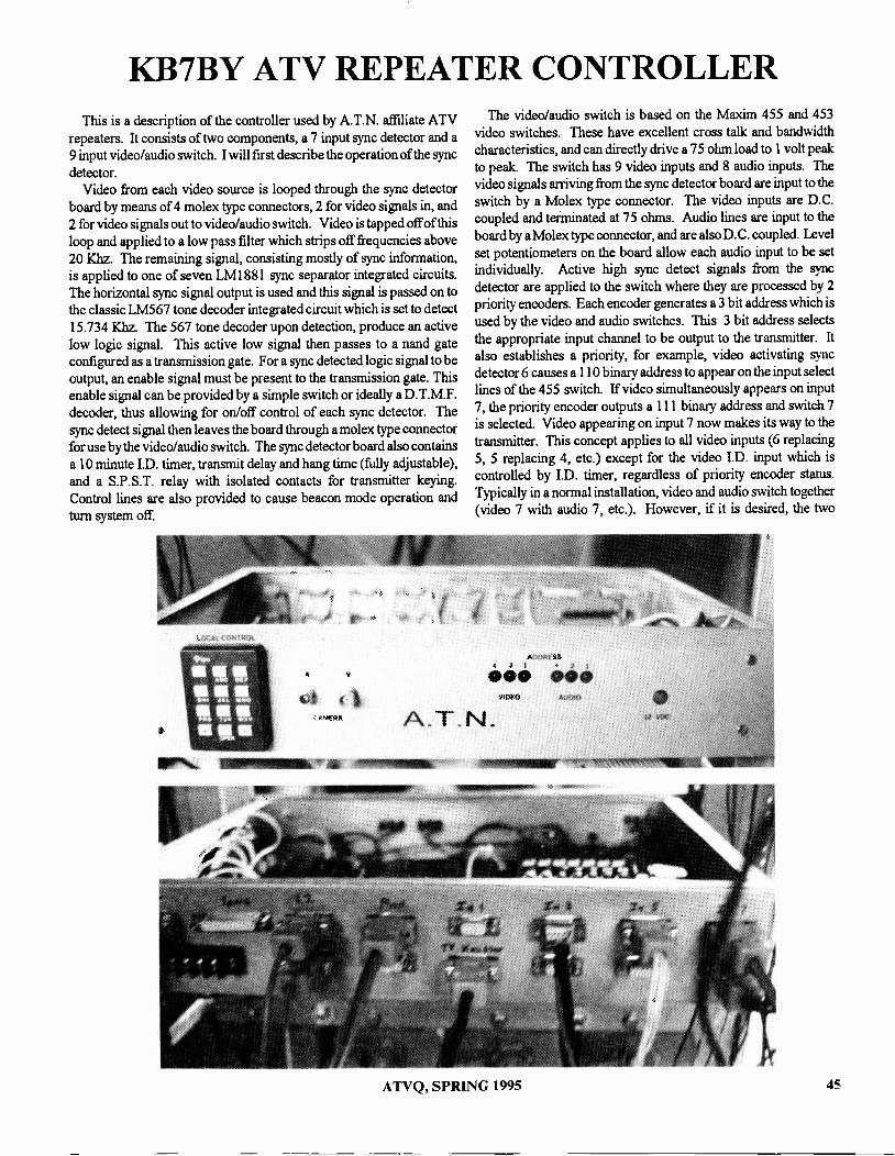
KB7BY ATV REPEATER CONTROLLERThis is a description of the controller used by A.T.N. affiliate ATV
repeaters. It consists of two components, a 7 input sync detector and a9 input video/audio switch. I will first describe the operation of the syncdetector.
Video from each video source is looped through the sync detectorboard by means of 4 molex type connectors, 2 for video signals in, and2 for video signals out to video/audio switch. Video is tapped off of thisloop and applied to a low pass filter which strips off frequencies above20 Khz. The remaining signal, consisting mostly of sync information,is applied to one of seven LM1881 sync separator integrated circuits.The horizontal sync signal output is used and this signal is passed on tothe classic LM567 tone decoder integrated circuit which is set to detect15.734 Khz. The 567 tone decoder upon detection, produce an activelow logic signal. This active low signal then passes to a nand gateconfigured as a transmission gate. For a sync detected logic signal to beoutput, an enable signal must be present to the transmission gate. Thisenable signal can be provided by a simple switch or ideally a D. T.M.F.decoder, thus allowing for on/off control of each sync detector. Thesync detect signal then leaves the board through a molex type connectorfor use by the video/audio switch. The sync detector board also containsa 10 minute I.D. timer, transmit delay and hang time (fully adjustable),and a S.P.S.T. relay with isolated contacts for transmitter keying.Control lines are also provided to cause beacon mode operation andturn system off.
The video/audio switch is based on the Maxim 455 and 453video switches. These have excellent cross talk and bandwidthcharacteristics, and can directly drive a 75 ohm load to 1 volt peakto peak. The switch has 9 video inputs and 8 audio inputs. Thevideo signals arriving from the sync detector board are input to theswitch by a Molex type connector. The video inputs are D.C.coupled and terminated at 75 ohms. Audio lines are input to theboard by a Molex type connector, and are also D.C. coupled. Levelset potentiometers on the board allow each audio input to be setindividually. Active high sync detect signals from the syncdetector are applied to the switch where they are processed by 2priority encoders. Each encoder generates a 3 bit address which isused by the video and audio switches. This 3 bit address selectsthe appropriate input channel to be output to the transmitter. It
also establishes a priority, for example, video activating syncdetector 6 causes a 110 binary address to appear on the input selectlines of the 455 switch. If video simultaneously appears on input7, the priority encoder outputs a 111 binary address and switch 7is selected. Video appearing on input 7 now makes its way to thetransmitter. This concept applies to all video inputs (6 replacing5, 5 replacing 4, etc.) except for the video I.D. input which iscontrolled by I.D. timer, regardless of priority encoder status.Typically in a normal installation, video and audio switch together(video 7 with audio 7, etc.). However, if it is desired, the two
ATVQ, SPRING 1995 45

KB7BY ATV REPEATER CONTROLLER
switches can be separated and inputs can be enabled separately.The KB7BY ATV repeater in Las Vegas, Nevada uses the following priority scheme:
Input 7 913 Mhz FM InputInput 6 434 Mhz AM InputInput 5 2.4 Ghz FM InputInput 4 2.4 Ghz FM Link InputInput 3 10 Ghz FM Input (future)Input 2 Amiga 500 visual telemetry computer (future)Input 1 Tower mounted cameraInput 0 Spare
If there is sufficient interest in PC boards, PC boards with all components installed, or complete controllers can be provided. Printedcircuit boards are double sided and have separate analog and digital ground planes. All video and audio traces are separated from each other by groundplanes. A 16 output microprocessor controlled D.T.M.F. decoder with user programmable site prefix is under development.
VIDEO INPUTS7
AU010 INPUTS, LOCALle;AMERA INPUT
INPUT ENABLE0 MI 0 OUT
CONNECT TO STIR SYNC UIDEO/AUDIODECODER (cnos ACTIVEHIGH) DETECTOR SWITCH7
BEACON MODE ENABLE IDENTIFICATION [NOBLEVIDEO AUDIO SELECT
REPEATER OFF/ON
TRANSMITTER KEYINGDRY CONTACTS
SYNC DETECTOR OUTPUTS
4H-- IDENTIFICATION UIOEO INPUT
BCD ADDRESS BUSSFOR FU URE LINK CONTROL
BOARDS
VIDEO OUT TO XMITTER
AUDIO OUT TO MUTTER
46 ATVQ, SPRING 1995

KB7BY ATV REPEATER CONTROLLER
3.00
0O00
C6, 0
I> °0
c_.
w
c.a)
cn
L.
Co
0O
0000OOOOO0
0O
00OOOOOOO0
00OO0OO0
C.
O
000
000
000
0 0 n
000
0 n 0
000
R15 0 1 10VR1
R23 0 0R14 01 0 06
VR2R22 0 0R13 O( _10 05
VR3C4
VR4 040 0 0 0 0 0 0 0 0 0
c51 o 1-1 0
0 0 0 0 0 0 0 0 0 0VR5 U5
C3
VIDEO/AUDIOSWITCHER
FF*7 938
VR6
VR7
VR85 RP1
R35 R240 0 0 0 0 50 0 [ 0R310 0 0 0 0 0 ,,.
R330 0 0 0 0 0'1R290 0 0 0 0 0 0R250 0 0 0 0 0R280 0 0 0 pp 0 01111R300 0 0 0 .C; 0R320 .- /0 0,..."...0 0 0o
0 f OR2 R90 0 U2 0 0C2 R340 0 C6C -c1) C8cE,CEA)
O 0O 0O 0O 0O 0O 0O 0O 0
U3 O
OOOOOO
O
b-00nCT
0O
ti
RP20000 .1-
21;:s)
01OO
0
o OR1
0 1 OR3
0(R4
Ol to
0 rjaal o
o Ta2-1 o
Or a8-]0R9
0 0R27
OO
OO
0
0 0 0 0 0 0 0 0 0 0 0 000-(4
0 0 0 0 0 0 0 0 0 0 0 0 0 OU4
0 R26
Clued) C5CF-0
R120( 10R2E3 0
R11 0 1 0
R19 0 F-1 0 02R10 0 ELT] 0
Ri8 0 0 DI
0 03O00(5OO
N
ti
0
.109 DIA4 PLACES
ATVQ, SPRING 1995 47

KB7BY ATV REPEATER CONTROLLER
O J6
08
012
R66
U21F-1
O
I 1
R61
f I
R60
011
J1A
VR1
O
C70K1
C72
I I
R65
R63
C71
C73
C78
C68 U19
C69
C77U20 R62
I 1
D10
C7 4
C7
I 1
R59
[1]6)
R57 R58
COMPONENT SIDEJ5
I. C.1
C8
C22
rs)
D19
I I
JIB
C2
C9
NJ
I I
C3
C10
E FiC24
J2A
C4
C11
C25
RI
RIR
r!Jr
C5
C12
C26
R 4R
329 0
I RSI
R71 1
CS I-1 C7C13 C14
C27 1= C28C20 MI C21
siA
1123 54 rg5
02 D3
F-R32' Ca_11Hb
PF1321:1A 10-92J4
tit
R32
CS5
J3A
U16 U18
338
SYNC DE T.
48 ATVQ, SPRING 1995

TRIDON 2000 NOW HAS A BIG BROTHERTHE TRIDON 2000H
DC -2
TRIDON 2000
TRIDON 200011
$109.95
$329.95
$459.95
THE TRIDON 200011 HAS ALL THE FEATURES OF THE TRIDON 2000 WITH MORE FEATURES SUCH AS:
*15 WATTS PEAK POWER (ADJUSTABLE) *LINE AND MIKE AUDIO INPUTS
*N TYPE ANTENNA CONNECTOR *BUILT IN LINE SAMPLER
*BIG HEAT SINK *CANIERA MONITOR OUTPUT
THE TRIDON 2000H RETAINS ALL OF THE ORIGINAL WYMAN RESEARCH FEATURES SUCH AS THE ON -CARRIERAUDIO SYSTEM AS WELL AS STANDARD SUB -CARRIER AUDIO SYSTEM
THE NEW WYMAN RESEARCH DC -2 HAS AN EXTREMELY SENSITIVE GaAsFET FRONT END AND IS HOUSED IN ANEW MATCHING TRIDON CABINET. THIS DOWNCONVERTER HAS AN OPTIONAL PROVISION FOR CRYSTALLOCKING OF TWO FREQUENCIES FOR ACCURATE REPEATER AND SIMPLEX RECEPTION.
WYMAN RESEARCH INC HAS A FULL LINE OF 450, 900, 1200 MHz AM AND FM ATV TRANSMITTERS, TRANSCEIV-ERS, RECEIVERS AND AMPLIFIERS. ATV AMPLIFIERS FROM MIRAGE AND RF CONCEPTS ARE IN STOCKPRICED FOR QUICK SALE.
WYMAN RESEARCH INC. IS AGENT FOR ATV MAGAZINES SUCH AS:ATVQ, BATC, VHF COMMUNICATIONS AND SPEC-COM.
WE ARE ALSO THE US AGENTS FOR THE WIDELY ADVERTISED SARAPARABOL E-600 FM -ATV RECEIVER BOARDSEEN IN SUCH MAGAZINES AS ATVQ. THE PRICE OF THESE BOARDS IS $199.95. THEY CAN BE USED FORSUPERIOR FM -ATV RECEPTION FOR THE 900 AND 1200 MHz BANDS WITH LITTLE MODIFICATION.
WRITE OR CALL FOR A CATALOG DESCRIBING EQUIPMENT THAT WILL PUT YOU ON ATV AT MINIMUM COST.OUR TRANSMITERS AND TRANSCEIVERS ARE THE MOST POWERFUL AND ECONOMICAL SOLD.
WYMAN RESEARCH INC.Don & Sue Miller Don and Sue MillerW9NTP 8339 S 850 WW9YL Waldron, IN 46182-9608
(317) 525 6452
MasterCard
INDIANA RESIDENTS 5% SALES TAXSHIPPING $6.00
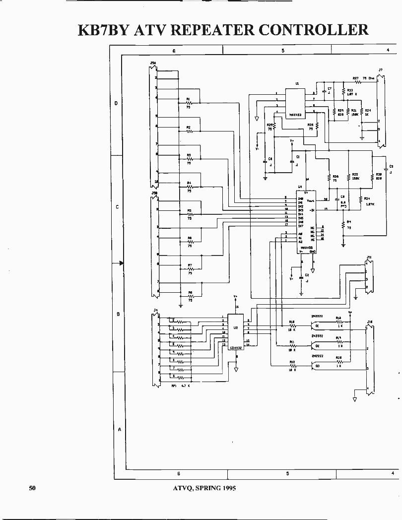
KB7BY ATV REPEATER CONTROLLER6 5
0
C
B
A
.354
M. v
75
7 \
434 %Yr
75
111144
J5475
J4
1J1
2
V1441453
R27 75 05.4 r\r1Wt
7.7707
K
42675
V
*425 * 431624 15614
42411(
CS
IS
U4
111
11
13
18
17
75
75
Re
75
2
v.
vo.t142
I9041
144
1/45
INK
1117
mcId mc -LiAl42
R2675
I Ca
1.8PCD
4321504
R9
75
*4741.17X
470628
V.
3 4Ak
i 4
2
1Ver--4
4
0
7,
7
U
7
CD 4532
-\r 15'1 4.7 K
- 14
K
242222R18
01 1 K
411
41102 1 K
111 K
etz2z/428
41203 14
K
252222
211
210
6 5
50 ATVQ, SPRING 1995

3 2 1
JILA
7
10
1 14
-Vt2.
T3 sy,
T 2 Ak
VR2
La K
N3
U K
VA,
U
K
V
le
U5
7
la11
1.1
YR,
K
YRS
10
17
K
2
a
7
T
T
7
r 6
11
11
12
RP2 4.7 K
113
.4532
AV
-IV
M.ALOG CPPOLAAO
DIGITAL GROuNO
3
213
V
V
D411
241
342Del 114
044
INS
INA
047
All
Al
12
NC
PC
PC
NC
mA0455Y- 000
REVISICNS
2CNE LTA DESCRIPTION DATE P/mRCT
A
CHANGE JO FROM 2 PIN TO 3 PD4MOVE Lt2-5 PROM V+ TO 211-3MOVE TRACE FRCP! 113-11 TO 03-4
t$
aA00 CS -Ca. R24-035 MO RI2DEL .T1-23CMANCE 24, 214 TO `I PIN CONNECTORS
4-12 C. T13.040
016
04.1
-Ul
2742222
11
-4
11(
0371.07 K
RI7
JO
a
1:30 4 I K
10 K
2frizzel 022
V.
21
05111 K
2N2222R23
PLO
06 I X
IA
ALCRO OUT
0
C
B
CPA* 0. mlX.OER matt VI
DECK©
OESI3CA
04134EEK
EIC
FILE ENIg61.15150471.1.5C
SCHEMATIC DIAGRAMVIDEO/AUDIO SWITCHER
MAC' remOvi4.
2
SIZE
socEI PF*793B l'471 w'
1 4-mAY-I192 6604
A
ATVQ, SPRING 1995 51

KB7BY ATV REPEATER CONTROLLER6 5 4
0
C
B
A
414
JIB
3'
RI
P2 C9
4,--1Mr--.4-{
10
J20
91R31/Wb
C2
JP1 C21
P15 "C22
IH-
1.3.1981
JP2
00U2
I
C
MB
C23
JP 3
U3
C3
II
4254 CII
4
it
7
RS C12
C5
II
R7\14.4
620 01,44
2
I
U411351
JP 4
U.
IF -
C32
R:9
C25
1M1851
JP)
U5
C13
II
if
I
7
1-4
C33
RI 9 "C26il-P12
881
JP 6
01
I3
4
7
Ca 4
R29 "
C27
II
RI 3
L1.1881
447
C1ll42
.1 L.C7
4
510 dd
C32
it
C55
R2I ^ Icze
7
I 691K
-
C49
U4567
U4567
U111
U1567
UI1
U4567
U4567
U13
U4567
4
247C56
4
LP.111181 U1567
6 5 4
52 ATVQ, SPRING 1995

4, 3 2 IREvISION3
LTR DESCRIRTICN GATE APPROVEDMaZONER22ICw.
RZ1 J311R54
CIr11.115 .134U17 UNC37 a WS DI -4-1 -CDP-3-. 4 2
3 4. i j5 4013 16114
8413 VIEmmilillill ..,,,..
.L.637 +1C75,'-f 7
6 aMC4143
22TTAN?
4 u113 MO0
02/1/ R27I.-UHTII C74
VI
C U2/
I
R311
4113
3 5 217 1.111-14,,r ..Nr.RCTR 14 3106
OLIJs..
J\r'_2_,___,U76
u2R31
:.12\f' R63 3 -_Z 15. 4,J,N..
--WV-2"oIN
5-A_t 5111C 41233 16.114 JsCT/ s4--t
/Vf
R64-- W.,,--11--erl
macl_....11--1--
7
2CT
3
__13_
--I- +-CT'
.__.03 R24
J5I II
12--I T isyCcW4
TART5314113 4161
.--33
& 1411 RS1V C *2.2K 4.7xU13
U17 J\r.C34
01
R32 067 ..,....3 R66 UM-.
2X 2N21417 C..8.v.
/Vf 7545104 R25
032
42 U15
Ut7CU is- Oa(-.
01
.16
4--. .N...
R65
Isom2t
111-1,322
305 AX
526
R33014=164311
52216
U18 .N.,4-
1154
ummillill Ak
4111
3LM711113
06 A" R27*AA + C71 ICd4 1 C6.3 IC66 1067 1066 C64il
34_c7.181+ C72
T
c73A
6 7:4TT TT:4TLA6
U18 as,r, ..N.-CS2
U15-14 U16-14 U17-14 U18-14 L14 -I6 121-14.1.1433 2 J\i"
/V07 028I
I.. m. .. ... . ..4Rai pc PARTS LIST
7 OM NI O. MULDER NOV 11111K USGU13 ..n.,
C63 7 OW= C. 701,40 OCT 42
0E3100.111 R.3
SCHEMATIC DIAGRAM ASY4 1426E24.7K .1\4.
NKU.D43 C. roma NOV 41 VIDEO SYNC SEPARATOR.7x - MC xxi.cits.m.soarnsOnof61Ec7 wrroro..
D- MENSrJ41
1 PF*1323A 1 sfir I of 1
IL3 2 1 311-OCT-1412 111.26
ATVQ, SPRING 1995 53

WHELKFl NDI. A9
OH 10
[14111.301
111,1
KROJFIU
C104n,L1 Oui
KHULWR
IN BUCYRUS, OHIO
ELKTRONICS12536 T.A. 77Findlau, OH 45840(419) 422-8206
INTRADLIVINa TICE
VDG-1
16,M4 Nal t1.2l I . C:3.I 0
Instant Video Source 4 Graphics Screens
(2 Hi-RES / 2 Colorbar)12 V D.C. Operation
- Video Relay for switching inlive camera video
Built-in Sequencer/Timer(Steps through all 4 screens)
VDG-1 with Pre-Progra mmedCustom Callsign Logo
- $99 ppd_(Quick -release socket option)
- $10Call or Write for CATALOG
of available GraphicsAdditional Programmed [PROMS
- $19now available as a Kit
-$ 89 ppd. Blank PCB - $19
KA8ZNYIGROYIEpORTIII
FlIIDLAY01110
KA8WLV111/14. t No ATV'Esi
ItAs c,ord Woe*

A TWO BAND WIDEBANDFM -TV RECEIVER
Bryan Davis, K3AAFSr. Engineer, Microdyne Corp.
I think most of you have heard of Microdyne...years ago theleader of Satellite TV receivers...well, they made several modelsthat are starting to show up in the used market that are useful forATV in the 910 Mhz and 1250 Mhz bands. The two models Ihave in mind are the 100 BKR and 1100 CKR. Both arefrequency agile using thumb wheel switches to set the RFfrequency. The CKR had fixed frequency audio sub -carrierdiscriminators. There was even a remote control (RS232)option for the BKR. The RF frequency tuned the standard CBand (3.7 - 4.2 Ghz) and Ku Band frequencies. But, since it wasworking with a Block Down Converter, it was really tuning the1st IF from 950 to 1450 Mhz.
Now, if you connect a 25 dB gain (min.) low noise preamp(connected to an antenna) to the IF input, you can tune 950 to1450 Mhz. But you had to set the RF frequency dial to 4.2 Ghzto receive 950 Mhz and 3.7 Ghz to receive 1450 Mhz. Eventhough the tuning was backwards, I could (with the aid of acalculator) figure out what to set the dial for to receive aparticular frequency. Well, all this doesn't get the Ham band at900 Mhz. So I proceeded to con (beg actually) an engineer thatwas involved with the software, to modify it to tune down to 900Mhz and up to 1500 Mhz...and do it with a direct readout on thethumb wheel switches. He finally did it and also kept the originaltuning for C Band and Ku Band. One other neat feature is themanual selection of Horizontal or Vertical polarization...thiscan be a preamp...antenna selection. In other words, you hookyour 900 Mhz antenna and preamp to Horiz. and your 1250 Mhzpreamp and antenna to Vert. (or vice versa).
The Second IF in these receivers are centered at 70 Mhz asmost TV Satellite receivers are. The CKR has one fixedbandwidth (LC), while the BKR had a selection of 4 (LC). Theadjacent channel rejection is not very good so I have beenthinking about using a SAW device to cure this problem. SAWdevices are available in bandwidths from 0.125 Mhz to 40 Mhzand about $100 each. I have a small quantity of 18, 24, 26, 36,and 40 Mhz bandwidth SAW filters.
The software is available from me for $25, (a $5 rebate if oldsoftware is returned). It is written in EPROM. You unplug theold EPROM and plug in the new one. Also, there is one otherchange one needs to do. The tuning voltage that tunes the 1st IFneeds to go down to about zero volts when tuning to 900 Mhz.The OPamp presently installed in the synthesizer board needs tohave 3 to 5 volts negative on pin 11. It presently is tied to groundwhich means that the output will not go much below +2 volts. Ihave used two ways to generate small negative volts. First is touse a MC79L05 with the input tied to neg. 15 volts, and secondis to use 4 diodes (1N914) in series with a resistor to the -15volts. The information on exactly how to do this will come withthe EPROM. Or, you can send your BKR/CKR to Hi -TechRepairs, Inc. which is a repair center for all non -warrantyMicrodyne Satellite TV and Telemetry receivers. Call DonPowell at 904-622-3635 or Fax 904-622-3978. One can shipequipment to Hi -Tech Repairs, Inc. located at 643B S.W. 15thStreet, Ocala, FL 34474. They have a large inventory ofSatellite receiver parts, boards and units. Incidently, Microdyneno longer services TV products.
RESULTS
I have one of these modified units on the receive end of a 912Mhz video link. The path is 12 miles and the transmitter isputting out 15 watts. It works very well. Ihave a loop yagi atthe RX site and a regular yagi at the TX site with about 200 feetof 1/2 inch foam hardline. Both antennas have about 13 dB ofgain and are about 150 feet above the ground. I have placed a 10and then 20 dB attenuator in front of the preamp and can not seeany difference between the 20 dB pad and no pad. A word ofadvice...do not use the 900 Mhz band for video if you are at ornear a cell site. I had to use a very good filter to get rid of theinterference coming from a 850 Mhz system.
I hope to have three of these modified units for sale at Dayton.The price is tentatively set at $1200.00 each.
ATVQ, SPRING 1995 55

Here are some of the notes that pass across my
ott
4400 °VI E-MAIL from anyVI
computer service :A
computer screen from America ()Mine.iREACH ATVQ
ATVQ @AOL.COM.
Subj: S band Antenna help -
95-03-19 From: Tomfaux
I'm conducting an experiment that would require aportable S -band (2.3 GHz) receiving antenna. Does any-one know what would be my best option (Yagi?, ParabolicReflector??), and manufacturer. I need at least 30 dB gainto reciever a very weak 300 KHz bandwidth signal. Pleasehelp. Tomfaux@aol
Subject: new 33cm rules Date: 95-03-19 From:[email protected] (Ed Taychert) Reply -to:[email protected] (The atv mailing list) To:[email protected] following is from a The VHF Journal, Vol46 Number 3, March 1995 (Newsletter of theRochester VHF Group)
NEW FCC REGULA-TIONS FOR THE 902-
928 MHz BAND(most of this is excerpted from FCC Report and
Order, 95-41, 6 FEB 95)FCC rules now state that "the band, 902-928 MHz,
is allocated on a secondary basis to the amateur servicesubject to not causing harmful interference to the opera-tions of government stations authorized in this band, or toLocating and Monitoring Service (LMS) systems."
Amateur operations in the 902-928 band have al-ways been secondary to the federal government operationand had to accept any interference from the operation ofIndustrial, Scientific, and Medical (ISM) devices. But, asof 6 February 1995, the FCC has allocated the whole 902 -
928 band to the LMS, secondary only to government sta-tions. This means that amateur operation in the 902-928band is secondary to LMS and must not cause "harmfulinterference" to LMS. (More on this later.) Part 15 de-vices are still secondary to the Amateur service.
LMS is the FCC's new name for the AutomaticVehicle Monitoring (AVM) service that has been aroundon parts of the 902-928 band since 1974. The FCC hasdivided LMS into two types of systems: multilaterationsystems and non-multilateration systems.
Multilateration systems use spread spectrum tech-nology to locate vehicles (and other moving objects) withgreat accuracy throughout a wide geographic area. Thistechnology is used, for example, by trucking companies tolocate and track their vehicle fleets, by municipal govern-ments to pinpoint the location of their buses, and by entre-preneurs who are developing subscriber -based, stolen ve-hicle recovery systems. Multilateration systems locate ve-hicles or other objects by measuring the difference of timeof arrival, or difference in phase, of signals transmitted froma unit to a number of fixed points, or from a number offixed points to the unit to be located.
Non-multilateration systems use any technologyother than multilateration technology to transmit data toand from vehicles passing through a particular location.This technology is now providing valuable services to stateand local governments operating various types of auto-mated toll collection systems - with an estimated 500,000cars currently served by such systems - and by the rail-road industry in the monitoring of their systems' railwaycars. A typical non-multilateration system uses an elec-tronic device placed in a vehicle to transfer information toand/or from that vehicle. When the vehicle passes near oneof the system stations, the station transmits an interroga-tion signal. The interrogation signal is then either modu-lated with unit -specific information and reflected back tothe station's receiver, or the tag transmits its own signal inresponse to the interrogation.
56 ATVQ, SPRING 1995

900 MHZ RULES...The FCC has defined specific sub -bands for the two
types of LMS systems:Band (MHz)System License 902.00 - 904.00Non-multilateration 904.00 - 909.75Multilateration 909.75 - 919.75Non-multilateration 919.75 - 921.75Multilateration & Non-multilateration 921.75 - 927.25Multilateration 927.25 - 928.00Multilateration (forward links)
LMS transmitters are authorized up to 30 WattsERP, but will typically be spread out over 2 to 12 MHz.(The energy from one of these transmitters received in a 3KHz bandwidth receiver, would be equivalent to that ofabout a 30 milliwatt narrow band transmitter.) In the927.25-928.0 MHz range, narrow -band forward link LMStransmitters are authorized with an ERP of 300 watts.
Most LMS equipment has been designed to oper-ate on shared frequencies. Much of it uses spread spec-trum techniques that minimize narrow -band interference.The new rules make it plain that the LMS service must beable to operate with other users of the band, including theseveral million Part 15 devices. The FCC states that thenew rulings "...seek to maximize the ability of Part 15 andamateur operations to coexist with the operation of LMSsystems."
Amateur and Part 15 users are prohibited from caus-ing "harmful interference" to LMS systems. Although theFCC has a definition of "harmful interference", it is somewhat subjective. So, as part of this rule making, the FCChas defined what "harmful interference" to LMS systemsis not. New FCC paragraph 90.361 states that if an ama-teur station (or Part 15 device) meets at least one of thefollowing two conditions, it is not causing harmful inter-ference to a multilateration LMS:
"(b) it does not employ an outdoor antenna; or(c) if it does employ an outdoor antenna, then if
(1) the directional gain of the antenna does not exceed6 dBi, or if the directional gain of the antenna exceeds 6dBi, it reduces its transmitter output power below 1 Wattby the proportional amount that the directional gain of theantenna exceeds 6 dBi; and(2)either(A) the antenna is 5 meters or less in height above ground;Or
(B) the antenna is more than 5 meters in height aboveground but less than 15 meters in height above ground andeither:
(i) adjust its transmitter output power below 1 Wattby 20 log (h/5) dB, where h is the height above ground ofthe antenna in meters"
After this definition of what is not harmful interfer-ence, the FCC states "We emphasize, however that Part 15or Amateur use is not restricted from operating beyondthese parameters. Part 15 and Amateur operations cancontinue to operate as long as interference is not caused..."
In other words, you can continue to operate in themultilateration sub -bands as long as no one complains. Ifa LMS licensee complains, you can change frequency to aspot where you do not cause them interference.
Or, you can reduce your antenna gain to 6dBi (atany power output up to the legal amateur limit). If youwant to keep your high -gain antenna, you will have to de-crease your power to 6dBw ERIP (0.5 watt into a 9 dBigain antenna or 0.25 watts into a 12 dBi gain antenna) ifyour antenna is at or lower than 5 meters above ground. (Ifthis doesn't make much sense, it is because the rule waswritten for Part 15 devices, that are already limited to 1.0watt/6dBw ERP, and then amateurs were added on also.)At 15 meters above ground you are limited to -4 dBw ERIP(50 milliwatts into a 9 dBi gain antenna or 25 milliwattsinto a 12 dBi gain antenna). Or put your antenna in yourattic (and run any ERP). Now you meet one of the FCC's"not causing harmful interference" conditions and the LMSmust accept any interference you cause them.
Reading the full Report & Order is interesting. Itcomprised 74 pages, of which only 13 are actual rulechanges. The remaining pages are a discussion of the vari-ous parties comments, how the FCC came to their deci-sions, plus dissenting and concurring statements of the com-missioners. The ARRL had commented on the proposedrules, mainly requesting a section of the band be set asidefor amateurs with a primary status. (This proposal wasnot accepted.) The ARRL stated "that there has been 'rapidincreases in amateur use', that 'the Amateur Radio Serviceis increasingly looking to the 902-928 MHz band,' and that`amateur use of the band has been growing,' the only quan-titative support that it provides is that there are 16 knownmanufacturers of amateur equipment for this band and thatthere are 20 amateur stations in Rochester, New York us-ing the band." (Its too bad that the ARRL couldn't havelooked at a few VHF & UHF contest results to come upwith some better numbers?)
ATVQ, SPRING 1995 57

900 MHZ RULES...One problem with the lengthy discussions in Re-
port & Orders is that they occasionally say or imply thingsthat are not detailed in the actual rule changes. The non-interference conditions above specifically refer to themultilateration sub -bands only. The rules definitely statethat amateur and Part 15 are secondary to LMS and maynot cause any harmful interference. Yet in the discussionby the FCC of solutions to multilateral interference prob-lems, they suggest that part 15 users (and imply amateursalso) use the 902-904 and 909.75-919.75 MHz sub -bandsthat will not be occupied by multilateration systems. Thisstatement implies that there will be no (or less?) "harmfulinterference" to the non-multilateration stations operatingin these sub -band, but there is nothing in the rules to sup-port this.
It was obvious from reading the Report & Orderthat the FCC had a difficult time trying to meet the wishesof all of the 902-928 MHz groups. At times they seemedalmost apologetic to the Amateur and Part 15 users fordumping LMS on them. One FCC commissioner dissentedthe decision and another who concurred, did so only be-cause it was "the best of three not very good alternatives."Both were concerned with the possible interference prob-lems and how sharing of the 902-928 band would con-tinue with increased growth of Part 15 and LMS systems.
For now, the amateur community can continue tooperate on the 902 band as it has been, it will be a fewyears before many of these systems go into operation. Onlytime will tell whether the band will remain useful, but youmight think of other alternatives before you plan any ma-jor projects for this band. Duncan Brown, K20EQ 73!
Subject: ATV Mailing List,900 MHz Amps,
From: (Mel Markowitz)To: [email protected] (ATVQ)
Hi Henry,
Just subscribed to the list and received the list ofcurrent subscribers. Hope the list will grow with increasedpublicity. I am in the Atlantic City, NJ area and am in theprocess of setting up a crossband 434 MHz in and 923MHz out repeater. Would be interested in obtaining a solidstate 923 MHz AB1 linear with about 100 watts out on thisfrequency. Does anyone have a model/manufacturer. Iheard that there may be a commercial amp available
through a company called TL. Anyone have any specificson this company? Thanks for any help. See you all againsoon.
Do you know of an ATV Internet list. I saw in yourlast issue a list at [email protected], but that seems to nolonger exist! If it does, how do I subscribe.
REPLY: Contact via e-mail TSTADER, (Terry, Stader)for complete info on the ATV net on AOL.
I'm putting together a crossband repeater andwould like to know ifyou have any leads on a good qualitylinear amp for 923.25 output (100 watts or so). I'm usinga PC Electronics transmitter to drive a DowneastMicrowave amp to about 18 watts. Thanks for your helpand reply. Mel Markowitz, K2JWD, 207 Alexander DriveLinwood, NJ 08221.
REPLY: 900 MHz amps are not plentiful since none ofthe ham suppliers are building any. We have published several900 MHz amps in ATVQ most are designed around variousbricks. Commercial cellular telephone sites have beenupgrading and tossing old amps, ranging from 35 to 150 watts.These are severely class C in operation but can be used on ATVwith sync stretching and at reduced drive, to stay within themore linear portion of the power curve of the amps.
Re:ATV@900 MHz with 'Rabbit'From: Bruce NOCV
3 or 4 ATV'ers here in the Twin Cities are usingrabbits for portable ATV operation. Some have added"bricks". Contact Rollie KBOGL for details. 73's, Bruce
From: John H DavisI'm wondering if anyone has had experience with
the Gemini VC -5000 version of the rabbit, whichapparently is crystal controlled. I don't have one of myown to play with yet, but the antenna seems to be mounteda bit differently (maybe not quite as easy to add an RFoutput jack to). Can anyone shed light on this? Thanks.
Dear Henry,Hi Henry it's Rick Keniuk (N9DUA). Our video repeateris on hold temporarily until we get some time and money.The repeater site is waiting for us. The current state offrequency usage will be 1252.00 FM video input, and915.00 FM video output. Both input and output will have5.8MHz subcarrier sound. The other channel for FM videoon 23cm in the Chicago area would be 1282.0MHz. Thisis placed directly between the voice repeaters at 1272 and1292. At this time 1282 would be best left as a simplexchannel or an input to a repeater. AM guys are on 1280.25.Enough for now lets see if this message makes it.
58 ATVQ, SPRING 1995

Subject: Where to get FCC forms?From: [email protected] (Edward A. Gutowski)The number for the FCC to obtain forms is 1-800-322-1117 , between 8 am and 4:30 pm EST.
I hope you are settled in your new home by now. Iwanted to drop you a note concerning the Ohio ValleyWireless Image Associations Repeater located inHuntington, WV. This repeater has been on the air sinceMay 94. The output is on 421.25 and input on 439.25Mhz. During the fall/winter months, we have made majorreceiving improvements by installing video and filters.
In the past year I have spent a great deal of time withSERA coordinators in getting the repeater coordinators inthe state of WV to approve coordination. I won't botheryou with the gory details, however, this past week Mr.Alex Hedrick, Jr. said he was holding up our coordinationagain because of the ARRL disapproval of the new 1994SERA 70cm bandplan. It appears that either Alex Hedrickor ARRL does not want any ATV on 70cm. SERA hasapproved a new 70cm bandplan providing one ATVrepeater on 421.25 out/434.00 input. We, OVWIA,agreed to change the input frequency to conform to thenew SERA bandplan. For now, it seems that 70cm ATV ison hold across the South Eastern part of the United States.
I will close on a higher note with the comment that Ihave enjoyed the past 70cm ATV band openings. BillBrown called by phone from Finley, OH on Dec 27 to turnon my ATV Equipment. He saw both the Huntington WVrepeater and my ATV even with his antenna pointing upinto the sky. EMF, ATV Bill? If you find out what is reallygoing on with SERA and the ARRL, please drop me a fax.My 24 hour fax number here is 606-928-2505, or voice606-928-6672. 73, Don Curry, WA4GSS
February CAATN Quarterly ATVSeminar
byMike Dees N3EZD
The Central Atlantic Amateur Television Network(CAATN) held its quarterly seminar on February 26, 1995,at Poor Jimmy's restaurant in Elkton, Maryland. Atten-dance was excellent in spite of the threatening weatherwith possibly the largest number people attending the semi-nar to date.
This seminar session was sponsored by the Balti-more Radio Amateur Television Society (BRATS) withBob, W3WCQ, serving as the program chairman. In addi-tion to Bob, BRATS was represented at the seminar byHeru W3WVV, Betty KA3RRK, Bob N3HAT, FredK3TAZ, Neil WA3ZQI, and myself.
The program had several very interesting topicsincluding, two presentations by Hem on his experimentswith cell phone power amplifiers and a modification whichadds color to the old diode matrix video ID generators, apresentation and demonstration by Bob W3WCQ on thenew 1200 MHz linear power amplifier offered by DownEast Microwave, a presentation by myself on the firmware
and the highlight of theprogram, a live demonstration of the 1 kW ATV stationbuilt by Bob Curry, KC3VO. This was the ATV stationthat was used with the Naval Academy's 10 meter dishantenna to send video to the space shuttle and was theonly station that the astronauts received in color. Therewere also discussions of intercity ATV linking, the Cana-dian and SERA proposed band plans for 440 MHz, and avideo tape of European .ATV activity from HB9AFO.
The next CAATN seminar will be held in Philadel-phia on June 11, 1995. Thank you Bob for putting togethersuch an interesting and informative meeting.
PITTSBURG PA ATV RPTThe Laurel Highland VHF Society sponsors an ATV repeater on 434.00 MHz inoput and dual outputs on 421.25
MHz and 923.25 MHz horizontal polarity. Voice coordination is on 146.670 MHz. Call ID W3NBN on 421.25, call IDKA3FZF on 923.25 MHz. Repeaters are located 35 miles south east of Pittsburgh, PA. 73 Robert W3NBN
ATVQ, SPRING 1995 59

SO YOU WANT TO BUILD AN ATV REPEATERPART 4 ANTENNAS
by Mike WA6SVT
The antenna system and the placement of it on the tower isone of the most important aspects of good coverage of therepeater. Lets first review antenna specifications.GAIN: Gain of an antenna over a reference source, wewill use dB over a 1/2 wave dipole.AZIMUTH PATTERN radiation of signal around the ho-rizon
ELEVATION PATTERN radiation of signal above/belowthe horizonNULL FILL some signal is used to fill in coverage be-tween the main lobe and the first minor lobe. It is used tofill in coverage for close in stations directly below themountain top or tall tower.DOWN TILT tle elevation pattern is tilted down, usually.5 to 6 degrees to properly illuminate the coverage ara.BANDWIDTH frequency range of low VSWR and maxi-mum antenna gain.
ELEVATION BANDWIDTH elevation beam tilt of theantenna with frequency. Usually with end fed collinearantennas. Normally if the antenna is cut higher than thefrequency you are using it till give some down tilt.WIND AND ICE The ability of the antenna to survivesevere climates.POWER. The ability of the antebnna to handle your kilo-watt repeater.
Is the highest gain antenna the one I want to use?Only in some cases. Most important is the azimuth andelevation patterns. Select an antenna that has a patternthat best fills in you coverage zone of the repeater. Livingout in Southern California, I have had many repeater groupsask; Why do I have problems directly below the site inhitting the repeater. I have the highest gain antenna frombrand X! The problem I have told them is that the gain ison the horizon and you are below the pattern. It may workvery well to talk to airplanes and other hill tops but youneed down tilt and possibly some null fill.
Because the earth is round the coverage area isalways below the horizon An exception to this is a site inthe floor of a valley surrounded by mountains. A goodrule of thumb is to use 2 degrees of down tilt for installa-tions that are between 3,000 and 6,000 feet above the cov-erage area (note not above sea level). At sites that are inthe 7,000 to 9.000 feet above the coverage zone 3 to 4degrees is a better choice. at sites that are below 1,000 feetdown tilt is usually not required but .5 to 1 degrees is nor-mally used on very high gain antennas. This elevation in-formation is applicable to both Vertical and Horizontalpolarized antennas.
What polarization should an ATV repeater have?It depends on many variables. Cochannel use by anothermode, personal preference, mobile operationetc. For hori-zontal antennas Lindsay Antennas from Canada has somegood ones that are suitable for mounting at a commercialsite. Ye Old Antenna Labs have some good designs too butneed a radome for mountain top use. For vertical polariza-tion you have a smorgasbord choice. Most of the commer-cial antenna manufactures have antennas that will covermost ham bands.
Comet and Diamond have 440 MHz 915 MHz and1280 MHz antennas comet has a 2.4 GHz antenna too.The comet and Diamond brands are an economical solu-tion for your needs. Most of these antennas have no downtilt. Using a 1280 -MHz antenna at 1253.25 MHz will give1 or 2 degrees of down tilt but at a Gust 0- a little gain andusually a 1.4 to ] VSWR. A new comer to the game isHustler's spirit line of super strong built to commercialstandards antennas. They have various gains, down tiltand null fill options.
They will also customize the antenna to your fre-quency. They are more expensive than the Comet and Dia-mond antennas but about 1/2 the cost of other commercialantennas. They also have come out with panel antennasfor controlled azimuth patterns.
Antenna feed lines should be 1/2 inch or largerhard-line or helix. Be sure to ground the outer conductorat the top of the tower, bottom of the tower and buildingentrance. Grounding kits for hardware cost several dollarsand you can substitute a hose clamp and braid or I 6 wirefor the ground wire. Use coax seal or rubber slicing tapeto Seal the outer conductor then several layers of goodquality electrical tape. Scotch coat the tape between at leastone of the layers of tape. Avoid sharp bends in the groundcable.
A final thought is to take some time and researchthe various manufactures to select the best antenna thatcovers your coverage area. Also try to wade though theantenna gain marketing hype. dBd is the gain you want toreference and look for the manufacture using the RS -329method for gain measurement. It is more realistic in actualantenna gain. Good luck and if you have any questionsabout ATV repeaters or antennas send me a letter and Iwill respond. My address is Mike Collis WA6SVT P.O.Box 1594 Crestline Ca. 92325.
60 ATVQ, SPRING 1995

BUILD YOUR OWN WHEEL ANTENNASfrom ATCO Newsletter
Table 1.
Band L A V h S Bd Td
70cm 26" 6" 6 1/4: 1/4" 1" 1" 1" 1 3/4"23cm 8 5/8" 2 1/8" 2 3/8" 5/16" 9/16" 1" 1" 5/8"
"L" = Total Element Length, "A" = 1/4 Side Length, "V" = Brass Plate to 1/2 Wave"h" = top to bottom plate distance "S" = Matching Stub Length Bd = Bottom Plate diameterTd = Top Plate Diameterd = approx distance between adjoining (top to bottom) elements at intersection of the 1/4 and 1/2 wave bend.
Sketch of Bottom View of Antenna
Top Plate (Td)
Nylon Spacer (h)
Bottom Plate (Bd)"N" Nut
"N" Female
"N" ConnectorBody DetailFigure 2
1/4 Wave
3 EachTotal Lan (1.1
'Stub'
JRites 3
Solder Element
1/4 Wave
Matching Stub
Solder Element
Top Plate Solders To 'N' Center ConductorVia 1/4' 12 Gauge Wire
Distance Between Too a & Bottom Plate 1/4'
ATVQ, SPRING 1995
1/2 Ways
61

BUILD YOUR OWN WHEEL
Antenna MountingTwo ways of mounting the Wheel are described here. Ifyou have an existing mast mounted on a Mag mount (likethe Hustler 22" short mast for HF) you can use it directly.All you need is a matching thread nut to secure the bracketon top of the mast. If you don't have a Hustler or similarmast, one can be made from 3/8" thread rod (found inmost hardware stores) cut 16-1/4" (5/8 wave on 70 cm)and fastened to a mobile magnet mount. The mounting ofthe "Wheel" antenna is a flat sheet aluminum bracket 2"long and 1-1/4" wide. Drill a 5/8" hole in the center 3/4"(center) from one end. Drill a 3/8 hole 5/8" in from theother end. 1-1/4 " wide.
Mount the antenna to the 5/8" hole and secure with asecond "N" connector nut. Mount the antenna to the mast.The antenna is now ready for tuning & testing. Use goodquality RG 8x feed line even for very short runs. RG 58has too much loss even at 400Mhz!Tuning & Testing the Wheel Antenna &Checking Resonant Frequency
Check the SWR on the frequency it will be used(ie 439.25 /427.25 or 1280/1255).If the VSWR is 1.2/1 or less, it will work fine for receiv-ing the output of the repeater. If the VSWR is very high (> 3:1), check for a feed line problem (connector?). If theVSWR is reasonable, no further tuning is necessary. Ifyou would like to fine tune the antenna, the followingprocedure worked for me:
A good quality watt/SWR meter (like a Bird 43or Diamond SX1000) for the 70 or 23 cm band is neces-sary to check out the antenna. Using a 440/1200 trans-mitter that will tune 430 to 450 Mhz, or 1250 to 1290plot the VSWR curve for the antenna. To raise the centerfrequency, bend each element (slightly) using pliers at thepoint the element soldered to the brass disks to separatethe 1/4 wave feed section; Gf the .,lover leaf (see Figure
4). Plot the curve again. Repeat as often as necessary toobtain the desired center.Checking the Pattern
A very rough check of the OMNI directional pat-tern can be performed by using the repeater BEACONmode as a signal source. Use a Decade attenuator boxto add enough attenuation to reduce the repeater signalto about "P2". In an "open" area and line of sight withthe repeater, rotate the antenna while mounted over thecar roof on the Mag mount. Watching the picture, youshould see no change in picture strength. The antennahas been measured with a far more sensitive equipmentto have -0.3db nulls 120 degrees apart in the OMNI pat-tern. Theses nulls can not be detected by watching theTV monitor (it takes 3db to change the picture 1/2 a "P"unit. If vOu have a sensitive IF AGC "P" meter on yourATV receiver, you may be able to detect the -0.3db nulls.A final word
Don't expect this antenna to perform like yourBeam or Loop Yagi! It does, however, perform like aHorizontal, OMNI Directional unity gain antenna. Us-ing the 70 cm version, I routinely copy the Columbusrepeater while mobile "P2" 40 miles from Columbus andthe 23cm version, I can see the repeater anywhere in theColumbus area (12-15 Miles), shorter distances whenthe leaves are on the trees!
If you would like to buy this antenna ready madeand tested, contact "The Olde Antenna Lab" in Denver,CO (303-798-5926). The basic antenna sells for $44.95and a Mag Mount version sells for $59.95.If you build this antenna, please let me know your expe-rience with it. I have a Wheel antenna mounted up about40 feet on my tower, if you would like to have a "Wheelto Wheel" contact, let me know! 73 & CU on ATVKen...WA8RUT
CORRECTIONWith the weight of the medical matters and flood
on my mind I should have known better than to trust mymemory! The old land ATV DX record was incorrectlystated. It should have been KAWA of Burlington, Iowaas the west end. The east end, K3POS was correct. Therecord was set on Thanksgiving, 1986. My thanks to
Paul Nees K A for bringing this to my feeble attention.Well, I was in the right neighborhood!
Now that life is back to normal (EKG now showsno problems) with just the usual pressures of the TV sta-tion activity and the wife's kennel business and working toget the antennas up, I should do better! 73 Henry KB9F0
62 ATVQ, SPRING 1995

All of our 23 cm Aerials are specifically designed for ATV use - although they can beused for other modes aswell. Wideband characteristics mean that you need only wit
aerial to cover the repeater input and output channels. Our famous wideband yagiscome fully assembled in two versions38 ELEMENT HIGH GAIN 14 dB gain. 1.8 ni long, E26.00 plus postage.18 ELEMENT STANDARD : 10 dB gain, 0.9 m long, E15.00 plus postage.Don't forget our 20 ELEMENT CONVERSION KIT, which converts your existing 18element aerial to the full 38 element high gain specification E13.00 plus postage.
Our 23 cm TROUGH REFLECTOR is quite unique, combining 11 dB gain with widebandwidth dad wide bearnwidth. les also compact, just 0.55 m high, 0.35 m wide and0.3 m deep. Supplied as a kit of predr lied and preformed parts, for easy 'screwdriverassembly E19.00 plus postage.
All aerials feature an SWR of less than 1.5.1 and aresupplies with mast clamps suitable for masts up to55 mm diameter. Mast poles shown are not supplied.
POSTAGE E3.75 for one aerial, E5.00 for two ormore. Telephone orders with cash on delivery :
E2.75 supplement per order. Orders horn outside ofthe UK - please write for carriage quotation.
CHEQUES payable to "SEVERNSIDE TELEVISIONGROUP' and send to 15. Witney Close, SsMord,Bristol 8518 3DX. Tel. 0272 860 422 I office hours),0225 873 098 I evenings & weekends I, Fax. 0272869 387. Please allow 28 days for delivery.
WORTHING & DISTRICT VIDEO
REPEATER GROUPGB3VR 6137VRB
AMIGA ATY PROGRAMThe Aniga ATV program a seen at the BATC show now has over 45 differentselectable testcards wits h a host of additional features including 21different wipes, full text control,now with 34 screens of textavailable, ORA talc, Tadstcard Music, Wettable displays. all cards aroverscan I. the whole screen is used.
Load In your an cccccc ised testcards, Largo characters, Scrolling 00000000 ,24Mr Clock, CIS extensions. Mot key 000000 ion, Doc reader,ATV CLI, Cross Hatch, Purity and also a comprehensive section forGen -lock
If your interested In ATV chow this Is for you. Two disk set, 1 Megrequired. Please state call sign and OLe (if know) when ordering. £26.61
1W FM -TV 24cm TRANSMITTERThis transmitter generates its singnal directly at the wanted frequency whichmay be set anywhere In the band colour or 1/0. On -board i for soundand fined pre-emphaels are standard features. The Mit includes diecast bogand cost [81.41
TWO CHANNEL PHASE LOCKED LOOP KITThis add on vastly improves the overall frequency stability of the I watttransmitter, Two crystal locked channel, and third fret running tuningposition are available. Nit price only £31.11Crystals for the PLL an channels RMT1.2.11 or simplex 1255Mha £1.11. Otherfrequencies to order.
VIDEO AGC KITThis unit accepts a c 00000 It. video signal In the range 1.15 to 2V P -P andoutputs a constant IV P -P atress 75 -Ohms. This unioue deals, is a mutt( forstations and (16.c II each.
THE SPECTRUM ATY PROGRAMThis 411X version has over 64 commands which includes 7 Testcards, memo rad,clock, naps, tones, locator salt (old 6 new). flag, x -hatch, various sloetext printing plus disk transfer command and more. All this for only E6.111Opus disk version [6.11 Oust for all spectrum owners.
BBC ILMLITEUR TELEVISION PRD66811 E8.58CROPREEIM LOD ON'S SELL f0B DETRILS
ORDERS TO:-TREASURER Of GB3VR. R.MSTEPMEMS
13 7GOIEU, 21 St.JAMES AVE,
LANCING,WESTBLESUSSEX. I5 01111. 4915764 7 to Pm
CREOUES PAYA TO:-'Worthing and District Video Repeater Group'
TO
HS PUBLICATIONS Aerials7 Epping CloseDerby DE3 4HR AmplifiersEngland
Technical Books0332 39 16 99
NEW!
Ike titikOlut IS ovAlimu Al 10.7S.IT LISTS LOTS OF PRODUCTS NO IttelICA111100
Nita to OW COMAIM.
DX -TV TUNINGSpecially heaped coseunccetion-styled. equipsent for
effective VIIF sad IMF DI -TV 'trestle., featuringvariable 1.1, el11011 bsniaidth. DovOle-fiederhelprinciple of operation; the D-100 concocts to the
eerie] Mat al a UNF TV thus providing additional I.F1..9.1, 1.1111.111 I. eupertor sensilivity AM
selectivity. IA rotary -dial TV, e.g, portal., etc,alloy. optima selectivity adiestoents le is achieved
sere cemienieolly).
VISION IF .18111TH REDUCTION
A reduced IS. bandwidth lilts the reception thresholdthug helping to reeolve mat Mauls that are .reallylost is the mina when using es 14-comerterl or e
oulti-etareterd TV receiver with its Morality .W* -04116100 I.F, slaw, Bandwidth reductios imroveeselectivity tee, thin 000 i o hog adierent Insane)respite., parliculerly in Banos I and Ill OafsInterleaved channel allocations earn.
TNE ULTIMATE IN DI -Tv RECEIVERS!
Our letnt seal, Ina D-100 sSUPERa, foetid. ME(Auteuil( kis and lendadth Control): as the signetMooed aroma the vision IF. Inflates widens, theeproclaim; maims picture panty. Rama' I.F, baraithcontrol le also provided.
PIKTI-STSTEll 5018 (via FR radio)
oatOIRIARIC ISMSCAN
-useful den en *ponies Is ieetnent.3 SIN. ediustable.
VIIF/U111 COVERS& (typical/
lands 1/11 (Le-band): ac -50 101. land Ill -230481,
170-15011/4 1170-6104Wa idstma tar battery).
3 Mebane I.F. output lactlity.
I Converted ostp(t: Ul channel it ladttntablet.
1101 P01018 FACILITY
Reim or car battery t 110V reran', ...Habil lop USA.
Each isavidually -cal ibrated unit tows apeolete with
tr.:traction, TV syelea sap and channel relationship
plan.
PRICE: UP 1124.1S line. PPM.Isirdr6.00 Alt SO Ali/USA add IRS 00 IIIDv versio
SYSTEM
A SeCCI4 'SPORADIC -E' e4Cleif SM1EM IS evalLABLE
MICK INCLUDES THE D -I00 sSUPElic DI -TV RECEIVER PLUS A
CMOICE OF LO -11110PERVII. 0511 1NE FOLLINIM SELECTIOR,-
Bill> I CROSSED DIPOLES (Cit--1000)3 Connect Internally for sulti-didectional reveres. oruse the switch provided to IA. 01en dipole separetely.
3 lb. sell and 1,11 clam rimas.
THREE 111.11/E111F1' ARRAY (1,1(-1:300)
Coves illand I channels (1-.).
t 16.11 outdoors where rotation is possible.
POUR ELEXHIT ARRAY (1(1,--14000
1 Coeds II -110 aft. 1 Ifsial for both TV and if 01-ing.
1,011001C d PACEASE. PRICE: E150700 :lac. Ur deltredy),
(Etardald sad 130.00. OSAYAid add (10.01/.
(ADD SS FOR ACCESS/VISA POURial FACIII1i)
To rind out sods .out TV 01 -is 011. .0i WA CO. .
copy of 11 -IV FIR BMWS' by Steen has& It IOC.
NO 11.10 )includes PAP AS and Europe).
SEE PS At he TELFORD MAHN RADIO RAU.
SuMDer SEPTEMBER ell.
Camtech Electronics -cib -1%-,.. le..e.ACI
21 Goldings Close, Haverhill, Suffolk, CB9 OEQ, UKter.
4rTel: INT +44 (0) 440 62779; Fax: +44 (0) 440 714147
c-deJr'
High Frequency Video Demodulator Card.Features 130 MHz IF input frequency, Plessey video demodulator.Switchable CCIR video de -emphasis + video invert and switchable meterfunctions. signal strength / tuning meter. Video output - 750 compositevideo. Audio demodulated outputs available are 6000 OdBm and 0.5 Wattloud speaker amplifier. This unit is to the highest quality construction usingplate -through hole PCBs with selective solder resist finish. Available in kitform or ready assembled.
Microwave Tuner / Down Converter.Features the very latest in commercial microwave integrated circuits andsurface mount technology. Ultra low noise PHEMT GaAsFET front endfollowed by stripline image filter and MMIC amplifier to a 5 GHz Gilbertcell mixer. Exhibits 35dB conversion gain and tunes (1.0) 800 to
1600 MHz. with an IF output up to 200 MHz. Also features an external LOoutput to drive a synthesiser, such as Camtech 2.4 GHz synth board. Unitcomes completely ready assembled with instructions.
TV Audio Modulator.A full featured audio modulator to compliment your video station. Containsmicrophone amplifier, 50us pre -emphasis filtering, speech compressor.15 kHz low pass filter and modulator / 5.5 to 6.0 MHz oscillator. Output isfully buffered and filtered to provide OdBm @ 750 modulated ± 50 kHz.Available in kit form or ready assembled.
For details on these items or a copy of our latest Catalogue, pleasewrite or phone to the address above. Credit card facilities available.

ELECTRONICS
VALUE PLUSQUALITYFROM OVER30 YEARSIN ATV
Shipped within24 hrs. of your call
ONLY$499'delivered UPS Made in USA
TC70-10 Transceiver lets you get on ATV right away with allthe power most will need in one box - *90 Miles line of sight
P.C. ELECTRONICS 2522 PAXSON LANE ARCADIA CA 91007-8537 USATOM (W6ORG) & MARYANN (WB6YSS) O'HARA (818)4474565
24 hr FAX order line (818) 447-0489
TC70-10 ATV TRANSCEIVER
AMATEUR TELEVISION 420-450 MHZTC70.10 TRANSCEIVER RECV TUNE
VMIT
MIC GAIN LINE GAIN VIDEO GAIN
All in one box
RUGGED
RELIABLE
POWERON
OFF
P C ELECTRONICS
ATV is no more difficult or different than anyvoice mode except that you also plug in yourcamcorder to transmit, and your TV set toreceive the picture. That's it - you're seeing aswell as talking to other hams live and in color!
You can show the shack, home video tapes, zoom in anddescribe projects, computer graphics and programs, repeatSSTV or even Space Shuttle Video and audio if you have aTVRO. Go portable or mobile, do public service events,RACES, AREC, CAP, even transmit the radio clubmeetings to those hams that can't make it out of the house.
DX is up to *90 miles snow free line of sight using 14 dBdbeams and 100 ft. of Belden 9913 low loss coax.
Transmitting equipment sold only to licensed Tech class orhigher Radio Amateurs, verified in the Callbook, and used forlegal purposes per 47 CFR part 97. If newly licensed, moved orupgraded, mail or fax a copy of your license or test certification.
F2 PTL MIC AUDIO VIDEO
0 0 tO 3F1
?_10 Wattsp.e.p. Out
o Adjustable peak envelope power RF outputTypical range from 2 to Watts allows proper adjustmentto fully drive the RF Concepts 4-110 or Mirage D1010 -ANNto full 100 Watts p.e.p., without sync or audio clipping.
o Separate mic and line audio volume controlsAllows voice over commenting when showing video tapes.
o Rugged 7.5x7.5x2.7" black die cast alum. boxContinuous duty for public service applications and takes upless space on the operating table than 1 Watt plus amp.
o True Final RF detected video monitor outputlets you set the video gain control for actual white level inyour video monitor. Camera video is at this phono jackduring receive for focus & lighting set up before transmitting.
Front panel phono jacks accept composite video and line audiofrom your camcorder or VCR. Mini jack for low Z dynamic mic &submini PTT. Type N antenna jack on rear panel. SensitiveGaAsfet downconverter tunes whole 420-450 MHz 70cm banddown to your TV channel 2, 3 or 4. Comes with one crystal youspecify on 439.25, 434.0, 427.25 or 426.25. Second switchselectable crystal add $20. Requires 13.8 Vdc @ 3 Amps.
Your TV set
Your video cameraor camcorder
COMPLETE 420-440 MHz 70cm BAND ATV STATION
TC70-10...$499+ ATV Transceiver
10 Watts p.e.p. min.13,8 Vde @ 3A power supply req.specify transmit frequency(s)
Optional 100 Watt Amplifiers Antennas - see pg. 5RF Concepts 4-110 $359Mirage 01010-ATVN $35925 Amp pwr supply req.
KLM 440-16X 14dBd $139KLM 440-10X 11 dBd $77KLM 440-6X 8.9 dBd $60
Remember when comparing prices, ours include UPS surface shipping in the cont. USA. 4/952509+ Mile DX set with our gear, KH6HME to WB6NOA & KC6CCC - - - Can you beat it?HAMS, call (818) 447-4565 now for your complete 10 page catalogue of our ATV products!