mutcd: roadway pavement markings - ced engineering · pdf filemutcd: roadway pavement markings...
TRANSCRIPT

MUTCD: Roadway Pavement Markings Course No: C06-015
Credit: 6 PDH
Gregory J. Taylor, P.E.
Continuing Education and Development, Inc. 9 Greyridge Farm Court Stony Point, NY 10980 P: (877) 322-5800 F: (877) 322-4774 [email protected]

INTRODUCTION This course discusses how to effectively use pavement markings to guide roadway traffic, and thereby reduce your liability exposure. The contents of this course are intended to serve as guidance and not as an absolute standard or rule. Its purpose is to help you to use the Manual on Uniform Traffic Control Devices (MUTCD) – Parts 3, 5, 7, 8 and 9 more effectively and not replace it. Should there be any discrepancies between the contents of this course and the MUTCD - always follow the MUTCD. Upon course completion, you should be familiar with the general design guidelines for pavement markings. The course objective is to give engineers and designers an in-depth look at the principles to be considered when selecting and designing for traffic control. For this course, the Manual on Uniform Traffic Control Devices for Streets and Highways (MUTCD) 2009 Edition will serve as a reference for the fundamental design principles of pavement markings. The MUTCD is recognized as the national standard for all traffic control devices installed on any street, highway, bikeway, or private road open to public travel. Any traffic control device design or application contained within it is considered to be in the public domain and available for use.
http://mutcd.fhwa.dot.gov/pdfs/2009/mutcd2009edition.pdf
Roadway Pavement Markings
Pavement markings are typically used for conveying laws and regulations, traffic and roadway conditions, and guidance and other information. These critical tools provide important information for safe travel on any U.S. roadway system. Roadway pavement markings are not a cure for all traffic problems. Road users process different types of visual and non-visual information differently: speed, roadway conditions, traffic, legal enforcement, noise levels, etc. Also, markings serve as reminders of important information, so road users do not have to memorize everything. The goal is to provide drivers with relevant information when they need it - resulting in safer, more efficient roadways with reduced liability risks. However, roadway pavement marking management can greatly reduce safety, contribute to roadway incidents, and increase liability exposure. The Standard Highway Signs and Markings book contains detailed specifications for all adopted standard signs and pavement markings. All traffic control devices have to be similar to or mirror images of those shown in this manual. Any symbols or colors cannot be modified unless otherwise stated.
http://mutcd.fhwa.dot.gov/SHSe/shs_2004_2012_sup.pdf
Copyright 2015 Gregory J. Taylor, P.E. Page 2 of 64

Roadway Pavement Markings
MANUAL ON UNIFORM TRAFFIC CONTROL DEVICES (MUTCD) By law (23 CFR 655, Subpart F), the Manual on Uniform Traffic Control Devices (MUTCD) is recognized as “the national standard for all traffic control devices installed on any street, highway, bikeway, or private road open to public travel”. It is the definitive authority for traffic signs and pavement markings. Nationwide consistency is the goal of the MUTCD by requiring uniform, understandable, and effective traffic control devices on all facilities open to public travel. It defines the nationwide standards for the installation and maintenance of the devices on all streets and highways. The MUTCD allows us to drive anywhere in the U.S. using the same basic signs and pavement markings with the same meanings. Drivers who see a particular marking should expect it to mean the same thing regardless of location.
The Federal Highway Administration (FHWA) publishes the MUTCD which establishes uniform standards for traffic control devices and promotes safety and efficiency on public roads. Road safety can be greatly increased by exceeding MUTCD requirements. Excessive methods should only be employed if a standard measure cannot meet the need. Otherwise, road users may tend to disregard the traffic control device.
Copyright 2015 Gregory J. Taylor, P.E. Page 3 of 64

Roadway Pavement Markings
The MUTCD has nine chapters (“Parts”) but since this course concentrates primarily on the subject of roadway pavement markings, we will focus mainly on Parts 3, 5, 7, 8 and 9.
1. General
2. Signs
3. Marking
4. Highway Traffic Signals
5. Traffic Control Devices for Low-Volume Roads
6. Temporary Traffic Control
7. Traffic Control for School Areas
8. Traffic Control for Highway-Rail Grade Crossings
9. Traffic Control for Bicycle Facilities
SHALL, SHOULD, and MAY The terms “shall,” “should,” and “may” have specific meanings when used in the MUTCD.
SHALL – Required, mandatory or specifically prohibitive practice. Any statements with “shall” conditions are typically used as a STANDARD in the MUTCD. These items cannot be modified or compromised. There is no allowance for discretion and they must be followed. SHOULD – Advisory or recommended practice in typical situations. Deviation is appropriate if justified by engineering judgment or study. Statements marked as “should” are used for GUIDANCE in the MUTCD. MAY – Permissive or optional practice without requirement or recommendation. Items marked as “may” are typically used in OPTION statements in the MUTCD and can contain allowable modifications.
Copyright 2015 Gregory J. Taylor, P.E. Page 4 of 64

Roadway Pavement Markings
SUPPORT statements do not contain the verbs “shall”, “should”, or “may”. These statements are for informational purposes only (without any mandate, recommendation, or enforcement). Road User The MUTCD defines a road user as “a vehicle operator, bicyclist, or pedestrian, including persons with disabilities, within the highway or on a private road open to public travel”. This group includes users of various skill levels and ages, pedestrians, wheelchairs, runners, rollerbladers, bicyclists, truck drivers, and motorcyclists. By meeting user needs, engineers can minimize any problems that the average road user may encounter. FIVE BASIC REQUIREMENTS OF TRAFFIC CONTROL DEVICES In order to be effective, any traffic control device has to be used in the right way. The MUTCD lists the following principles to be used when selecting and applying each device: 1 - Fulfill a need
A device should only be installed if there is a need for warning, regulation or guide information. It is also vital to use markings that fulfill that need. If a need exists and the sign in question does not meet that need, use something else. Overusing pavement markings can lead to disrespect and loss of emphasis value while underuse can result in persistent but correctable safety problems.
2 - Command attention
Standard roadway markings are designed to be noticed and catch the attention of road users. The high-contrast color combinations were chosen due to their ability to stand out and be easy to read. Maintenance is the key to remain eye-catching. All markings need to be kept in good working order. They need to reflect light at night, and not be faded, cracked, or peeling. Pavement markings in bad condition are unable to command attention, day or night.
3 - Command respect
Road users are expected to willingly obey warnings and regulations that obviously fulfill a need. Markings that seem unneeded or unreasonable are regularly disobeyed. Good management and maintenance is crucial to commanding respect
Copyright 2015 Gregory J. Taylor, P.E. Page 5 of 64
Roadway Pavement Markings
for traffic control devices. Amateurish, homemade or damaged pavement markings are more likely to be disregarded.
4 - Have one simple message
Traffic control devices need to communicate its message in a way that is clear and readable. By using standard pavement markings in the MUTCD that have been researched and evaluated by the FHWA, most drivers should understand their meanings.
5 - Provide adequate time for proper response
Traffic control devices should meet or exceed MUTCD standards so drivers have adequate time (Perception-Response Time – PRT) to react. Drivers need to have the time and distance to take the appropriate action before they reach a situation. If not, insufficient response time may result in roadway crashes. Traffic speed is an important factor for determining driver response time. Vehicles operating at high speeds need longer response time and more distance to react. This increased distance can be obtained by placing pavement markings in advance of the location where the information is needed.
Using the five basic requirements will help make your traffic control devices more effective. Design, placement, operation, maintenance, and uniformity should be taken into consideration to maximize the ability of a device to meet these principles. However, by disregarding the five requirements, you may find that road users disregard your traffic control devices. READIBILITY and RETROREFLECTIVITY Drivers must be able to read a traffic control devices from a reasonable distance and have adequate reaction time to safely travel the roadway. As the national population gets older, the average driver gets older, and people continue driving at older ages. Improving nighttime visibility of signs and pavement markings becomes more important as the traveling public gets older. As we age, our eyes gradually become less light sensitive. Retroreflectivity is the ability of a traffic control device to reflect light from its surface back to its original source. Retroflective markings can be used for increasing nighttime visibility. Maintaining retroreflectivity is a crucial element of traffic safety since fatal night crashes occur approximately three (3) times as often as daytime traffic fatalities.
Copyright 2015 Gregory J. Taylor, P.E. Page 6 of 64
Roadway Pavement Markings
Retroreflectivity Elements Light source (vehicle headlights) Target (traffic control device) Receptor (driver’s eyes)
Technologies involving glass beads or prismatic reflectors are more visible and bright since more light is reflected directly back to the original source. New materials or methods can be used as long as the traffic control devices meet the standard color requirements. Pavement marking design should be uniform without any decrease in:
visibility,
legibility, or
driver comprehension during day or night conditions.
Copyright 2015 Gregory J. Taylor, P.E. Page 7 of 64

Roadway Pavement Markings
PAVEMENT MARKINGS Pavement markings are more than roadway striping. They are part of a guidance system for relaying regulatory and vehicle-path information to the user - without requiring them to divert their attention from the road. Markings are used to encourage safe, orderly traffic flow and optimize roadway capacity. To be effective, pavement markings need to be readily recognized and understood. A uniform system of marking color, shape, and application has been developed to convey the same message each time a pavement marking is encountered. All pavement markings should be properly maintained to ensure good daytime and nighttime visibility. Once a municipality has made the decision to install a marking, it is their responsibility to maintain it. If the municipality decides that the marking is no longer needed, documentation of the decision process should be recorded. Pavement markings deemed non-applicable or confusing should be removed as soon as practical. COLORS
White: Separates traffic traveling in the same direction Delineates the right edge of the roadway
Yellow : Separates traffic flows in opposite directions
Delineates the left edge of divided/one-way highways and ramps Differentiates two-way left-turn lanes and reversible lanes from other lanes
Blue: Supplements white markings for handicap parking
Purple: Supplements toll plaza approach lane lines or edgelines restricted for
registered electronic toll collection vehicles Black: Used with other pavement markings (yellow, white, red, blue, or
purple) for light-colored pavements that do not provide sufficient contrast
Copyright 2015 Gregory J. Taylor, P.E. Page 8 of 64
Roadway Pavement Markings
MATERIALS The color, pattern, and orientation of pavement markings provide crucial information to roadway users. Compliance with these standards is critical for providing positive guidance and should be maintained throughout the useful life of the markings. Materials that minimize tripping or loss of traction to pedestrians, bicyclists, motorcycles, etc. should be considered when choosing pavement markings. Pavement markings typically include paints and thermoplastics - but other marking materials (colored paving, raised pavement markers, etc.) may also be used. Highly visible delineators and channelizing devices can also be installed similar to those methods for signs. Paint is the easiest, cheapest, and most commonly used pavement marking material - but it is also the least durable. For poor nighttime visibility, retroreflectivity can be improved by adding glass beads into the wet paint. Thermoplastic pavement markings use temperature-setting plastics that are heated to their melting point for use on asphalt paving. Due to the temperature-related expansion and contraction differentials between plastic and concrete (which can result in thermoplastic separation), thermoplastic is generally unsuitable for use on concrete paving. LONGITUDINAL MARKINGS Longitudinal markings are generally placed parallel and adjacent to traffic flow – lane lines, center lines, edge lines, channelizing lines, etc. These markings guide traffic along the roadway by providing visual clues to the travel path.
Longitudinal Line Functions: Double Line: Maximum or special restrictions Solid Line: Discourages or prohibits crossing (depends on application) Broken Line: Permissive condition Dotted Line: Provides guidance or warning of lane function changes ahead
The widths and patterns of longitudinal lines shall be as follows:
Normal line - 4 to 6 inches wide
Copyright 2015 Gregory J. Taylor, P.E. Page 9 of 64

Roadway Pavement Markings
Wide line - minimum of twice the width of a normal line The line width indicates the degree of emphasis.
Double line - two separated parallel lines Broken line - normal line segments (10 feet) separated by (30 feet) gaps Dotted line - noticeably shorter line segments (2 feet) separated by shorter gaps
(2 to 6 feet) when used for intersections and tapers - 3 feet line segments with 9 feet gaps when used for lane lines. Line width is at least the same as the width of the line it extends.
White or yellow broken lines permit vehicles to pass or change lanes. As stated above, these markings are applied with ten foot painted dashes and thirty foot spacing. Therefore, the distance from the beginning of one dash to the beginning of the next dash is 40 feet. By knowing this information, an individual can estimate distances along roadways very quickly. For example, if there are three dashes between two side roads; then the estimated distance equals 120 feet separating the roadways (3 x 40). YELLOW CENTER LINE PAVEMENT MARKINGS & WARRANTS Yellow center line pavement markings separate opposite traffic lanes for roadways. These markings can be installed at locations that are not the exact center of the roadway. Short sections on roads (without continuous center line markings) may be marked with center line pavement markings to control traffic, where necessary - curves, hills, grade crossings, bridges, etc.
Copyright 2015 Gregory J. Taylor, P.E. Page 10 of 64

Roadway Pavement Markings
Copyright 2015 Gregory J. Taylor, P.E. Page 11 of 64
Roadway Pavement Markings
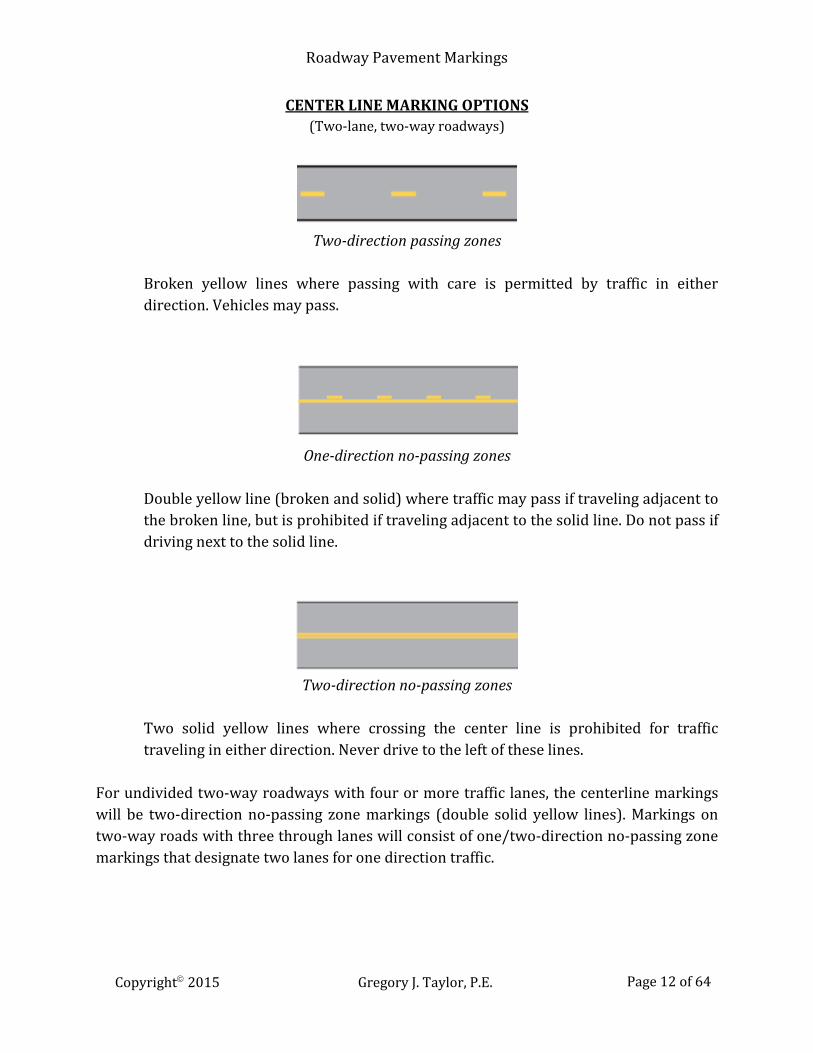
CENTER LINE MARKING OPTIONS (Two-lane, two-way roadways)
Two-direction passing zones
Broken yellow lines where passing with care is permitted by traffic in either direction. Vehicles may pass.
One-direction no-passing zones
Double yellow line (broken and solid) where traffic may pass if traveling adjacent to the broken line, but is prohibited if traveling adjacent to the solid line. Do not pass if driving next to the solid line.
Two-direction no-passing zones
Two solid yellow lines where crossing the center line is prohibited for traffic traveling in either direction. Never drive to the left of these lines.
For undivided two-way roadways with four or more traffic lanes, the centerline markings will be two-direction no-passing zone markings (double solid yellow lines). Markings on two-way roads with three through lanes will consist of one/two-direction no-passing zone markings that designate two lanes for one direction traffic.
Copyright 2015 Gregory J. Taylor, P.E. Page 12 of 64
Roadway Pavement Markings
Required Center Line Pavement Markings
Paved urban arterials & collectors Traveled way 20 feet or wider ADT = 6000 vehicles/day or more** Paved two-way streets or highways Three or more lanes Rural arterials & collectors Traveled way 18 feet or wider ADT = 3000 vehicles/day or more Where engineering judgment indicates a need **May be used for a minimum ADT of 4000 vehicles/day
ADT estimates based on engineering judgment may be used if traffic counts are unavailable. Center line markings may be placed on paved two-way roads with a minimum width of 16 feet. NO-PASSING ZONES No-passing zones should be used on two- and three-lane roads (with center line markings) where engineering studies indicate that passing must be prohibited due to inadequate sight distance or other special conditions.
Typical No-Passing Zone Locations Lane reduction transitions Obstruction approaches (must be passed on right side) Grade crossings Highway-rail grade crossings Inadequate sight distance locations
The MUTCD mandates using either one-direction or two-direction no-passing zone pavement markings. No-passing zone signs may be used in addition to markings for emphasizing the limits of a no-passing zone.
One-direction no-passing zone markings Double yellow line – one normal broken and one normal solid. Passing is permitted for traffic adjacent to the broken line and prohibited for traffic adjacent to the solid line.
Two-direction no-passing zone markings Double solid yellow lines that prohibit passing in either direction.
Copyright 2015 Gregory J. Taylor, P.E. Page 13 of 64

Roadway Pavement Markings
Passing Sight Distance Definitions Vertical Curve:
Distance at which an object 3.5 feet (42 inches) above the pavement surface is visible from a point 3.5 feet above the pavement
Horizontal Curve:
Distance along the centerline (right-hand lane line for 3-lane road) between two points 3.5 feet above pavement on a line tangent to the embankment or obstruction that cuts off visibility on inside of curve.
These values are for operational use and may be less than the geometric design values found in the AASHTO “Green Book”.
No-passing markings are needed for connecting successive no-passing zones that are less than 400 feet apart.
Copyright 2015 Gregory J. Taylor, P.E. Page 14 of 64

Roadway Pavement Markings
Copyright 2015 Gregory J. Taylor, P.E. Page 15 of 64

Roadway Pavement Markings
Upstream point “a” is where the sight distance first becomes less than the minimum values. Downstream point “b” is the point where the sight distance is again greater than the minimum.
For three-lane roadways with center lane transitions from one direction to the other, a no-passing buffer zone should be located in the center lane. This buffer should consist of a flush median island with two sets of double yellow center line markings - a minimum length of 50 feet with lane-reduction transitions at each end. Yellow diagonal crosshatch markings can also be used in the flush median area between the two sets of no-passing zone markings.
LANE TRANSITION TAPER LENGTHS (3-Lane Roadways)
Speed Limit Formula
Less than 45 mph L = WS²/60 45 mph or more L = WS L = Taper length (ft) W = Center lane width or offset distance (ft) S = 85th percentile speed or statutory speed limit (whichever is greater)
Minimum Lane Transition Taper Lengths 100 feet Urban areas 200 feet Rural areas
Copyright 2015 Gregory J. Taylor, P.E. Page 16 of 64

Roadway Pavement Markings
Copyright 2015 Gregory J. Taylor, P.E. Page 17 of 64
Roadway Pavement Markings
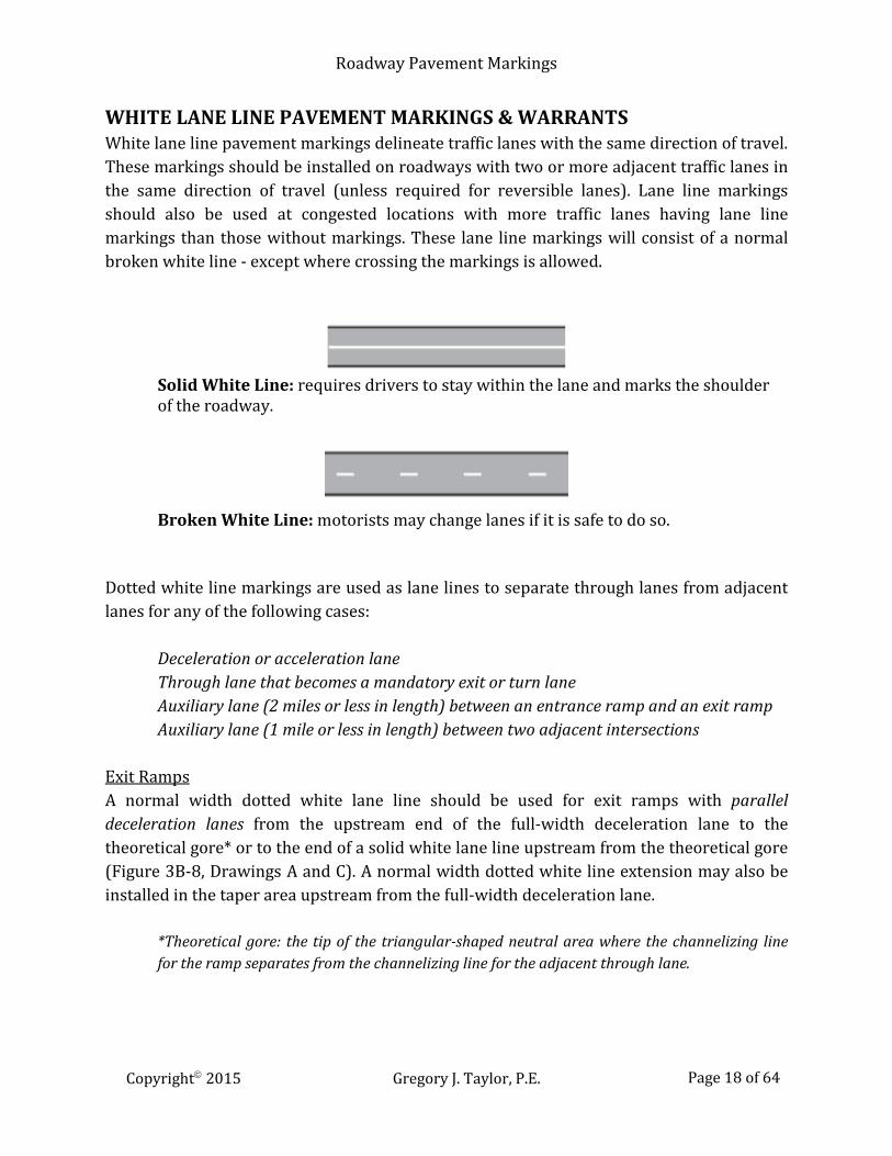
WHITE LANE LINE PAVEMENT MARKINGS & WARRANTS White lane line pavement markings delineate traffic lanes with the same direction of travel. These markings should be installed on roadways with two or more adjacent traffic lanes in the same direction of travel (unless required for reversible lanes). Lane line markings should also be used at congested locations with more traffic lanes having lane line markings than those without markings. These lane line markings will consist of a normal broken white line - except where crossing the markings is allowed.
Solid White Line: requires drivers to stay within the lane and marks the shoulder of the roadway.
Broken White Line: motorists may change lanes if it is safe to do so.
Dotted white line markings are used as lane lines to separate through lanes from adjacent lanes for any of the following cases:
Deceleration or acceleration lane Through lane that becomes a mandatory exit or turn lane Auxiliary lane (2 miles or less in length) between an entrance ramp and an exit ramp Auxiliary lane (1 mile or less in length) between two adjacent intersections
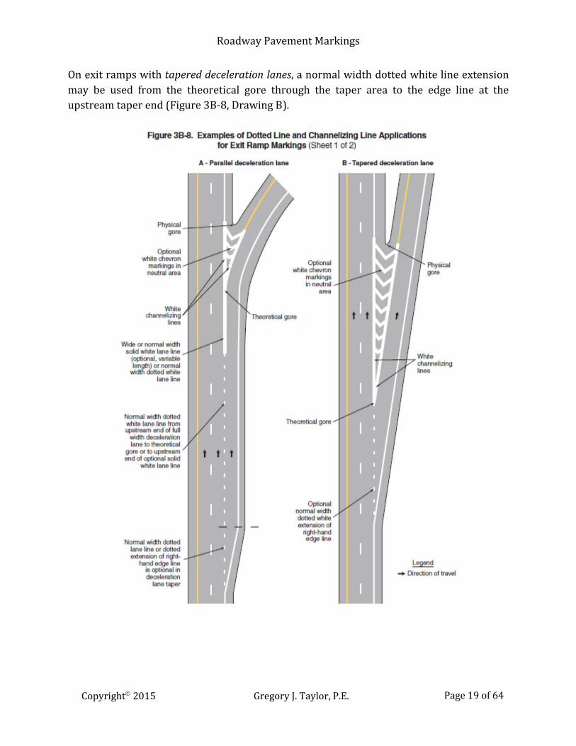
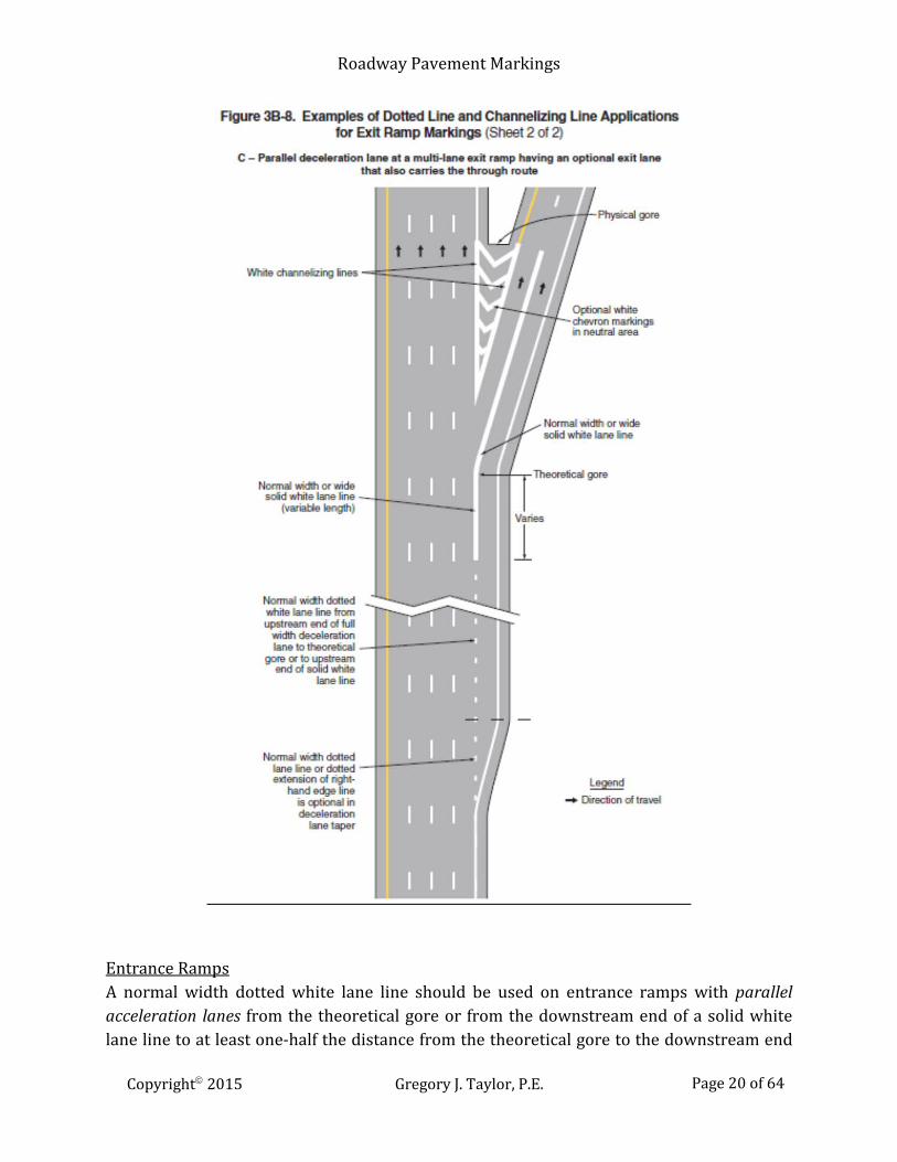
Exit Ramps A normal width dotted white lane line should be used for exit ramps with parallel deceleration lanes from the upstream end of the full-width deceleration lane to the theoretical gore* or to the end of a solid white lane line upstream from the theoretical gore (Figure 3B-8, Drawings A and C). A normal width dotted white line extension may also be installed in the taper area upstream from the full-width deceleration lane.
*Theoretical gore: the tip of the triangular-shaped neutral area where the channelizing line for the ramp separates from the channelizing line for the adjacent through lane.
Copyright 2015 Gregory J. Taylor, P.E. Page 18 of 64
Roadway Pavement Markings
On exit ramps with tapered deceleration lanes, a normal width dotted white line extension may be used from the theoretical gore through the taper area to the edge line at the upstream taper end (Figure 3B-8, Drawing B).
Copyright 2015 Gregory J. Taylor, P.E. Page 19 of 64
Roadway Pavement Markings
Entrance Ramps A normal width dotted white lane line should be used on entrance ramps with parallel acceleration lanes from the theoretical gore or from the downstream end of a solid white lane line to at least one-half the distance from the theoretical gore to the downstream end Copyright 2015 Gregory J. Taylor, P.E. Page 20 of 64
Roadway Pavement Markings
of the acceleration taper (Figure 3B-9, Drawing A). A normal width dotted white line extension can also be installed from the downstream end of the dotted white lane line to the downstream end of the acceleration taper. For entrance ramps with tapered acceleration lanes, a normal width dotted white line extension may be used from the downstream end of the channelization marking adjacent to the through lane to the downstream end of the acceleration taper (Figure 3B-9, Drawings B and C).
Copyright 2015 Gregory J. Taylor, P.E. Page 21 of 64

Roadway Pavement Markings
Copyright 2015 Gregory J. Taylor, P.E. Page 22 of 64

Roadway Pavement Markings
USES OF WIDE DOTTED WHITE LANE LINES In advance of freeway route splits with dedicated lanes
Lane drop marking in advance intersection lane drops to distinguish a lane drop
from an intersection through lane
To separate a through lane that continues beyond an intersection from adjacent auxiliary lanes between two intersections
Lane drop marking in advance of exit ramp lane drops to distinguish a lane drop from a normal exit ramp
To separate a through lane that continues beyond an interchange from an adjacent auxiliary lane between an entrance ramp and an exit ramp
Lane Drop Markings Lane drop markings used in advance of exit ramps should start a minimum of 1/2 mile in advance of the theoretical gore. Lane line markings should be used on multi-lane exit ramp approaches with optional exit lanes for through traffic. If the right-most exit lane is an added lane (i.e. parallel deceleration lane), the marking should begin at the upstream end of the full-width deceleration lane. Lane drop markings used in advance of intersection lane drops should begin a distance that is determined by engineering judgment as suitable to enable drivers (not making the mandatory turn) to exit the lane being dropped before reaching the queue of waiting vehicles. This marking should start no closer than the most upstream sign associated with the lane drop. Dotted white lane lines used for lane drops and lane lines separating through lanes from auxiliary lanes consist of 3-foot line segments separated by 9-foot gaps. Normal or wide solid white lane line markings should be used where crossing lane line markings are discouraged, Wide solid lane line markings may be used at different locations for greater emphasis.
Copyright 2015 Gregory J. Taylor, P.E. Page 23 of 64
Roadway Pavement Markings
Solid double white line markings should be used where crossing the lane line markings is prohibited. EDGE LINE PAVEMENT MARKINGS Edge line pavement markings delineate roadway edges. These are valuable as visual references during adverse weather and visibility conditions. Edge lines should not be continued through intersections or major driveways. For divided highways, one-way streets, or ramps - normal solid yellow lines can be used to delineate the left-side of a roadway or to indicate restrictions left of these markings. Normal solid white lines can be used for delineating the right-hand edge of the roadway. Wide solid edge line markings can be used at locations with a need for greater emphasis.
Warrants for Use of Edge Lines Edge line markings must be used on roadways with the following characteristics:
Freeways Expressways Rural arterials* *Minimum traveled way width of 20 feet with a minimum ADT of 6,000 vehicles per day
Edge lines are also recommended on the following roadways: Rural arterials and collectors (20-ft minimum traveled way and a minimum ADT
of 3000 vehicles/day) Where engineering judgment indicates a need
Edge line pavement markings can also be used on roads with or without center line markings.
RAISED PAVEMENT MARKERS (RPM) Raised pavement markers can supplement or substitute for roadway pavement markings. These may be either retroreflective or non-retroreflective with prismatic cube-corner reflectors used for necessary retroreflective properties.
Copyright 2015 Gregory J. Taylor, P.E. Page 24 of 64

Roadway Pavement Markings
Advantages of Raised Pavement Markers Increased visibility under adverse weather conditions Better durability than markings Tactile and audible warnings Use as transverse rumble strips
The color of RPMs under both daylight and nighttime conditions needs to conform to the color of the marking for which they serve, supplement or substitute. Retroreflective or internally illuminated raised pavement markers can be used in the roadway bordering curbed approach ends or on top of raised medians and island curbs. These markers are available in mono-directional and bidirectional (capable of displaying the applicable color for each direction of travel). All internally illuminated markers must be steadily illuminated and not flash when used. Non-retroreflective raised pavement markers should never be used alone as a substitute for other types of pavement markings without supplemental retroreflective or internally illuminated markers. Directional configurations should maximize correct information and minimize confusing information from visibility of markers that do not apply to the road user. The spacing of retroreflective RPMs should correspond with the pattern of broken lines (40-ft for normal rural roadways) for which the markers serve, supplement or substitute. Nonreflective markers for broken-line segments should be used in groups of three to five – depending on the normal lane marking length. For additional emphasis, retroreflective raised pavement markers may be spaced closer than described in the MUTCD if determined by engineering judgment. The “Traffic Control Devices Handbook” contains further details pertaining to the spacing of raised pavement markers for longitudinal markings.
Disadvantages of RPMs High installation costs Susceptible to damage or removal
Raised pavement markers must be protected from snowplow blades in locations susceptible to snowy conditions. Snowplowable markers are encased in durable castings designed to guide blades over the marker – while standard markers can be recessed below the roadway surface to prevent damage.
Copyright 2015 Gregory J. Taylor, P.E. Page 25 of 64
Roadway Pavement Markings
STOP & YIELD LINES Stop and yield lines are transverse pavement markings used to inform drivers where to should stop or yield when approaching an intersection or mid-block crosswalk. These markings are typically white lines that are perpendicular to the travel path (stop lines, yield lines, crosswalks) as well as special markings (symbols, word markings, channelization markings, etc.). A stop line informs drivers where they are required to stop at an intersection or roundabout controlled by a stop sign or traffic light. These line markings should be 12 to 24 inches wide. Stop and yield lines should be placed a minimum of 4 feet in advance of the nearest crosswalk at controlled intersections (except for yield lines at roundabouts or at mid block crosswalks). For locations without marked crosswalks, the stop line or yield line should be placed at the desired stopping or yield point, a minimum distance of 4 feet (with a maximum of 30 feet) from the nearest edge of the intersecting traveled way. Stop line locations should allow sufficient sight distance to all other approaches for an intersection. However, stop lines should not be used where drivers are required to yield or on uncontrolled approaches where drivers are required to yield to pedestrians. For midblock signalized locations, stop lines should be placed a minimum distance of 40 feet prior to the nearest signal indication. Yield lines (also called Shark’s Teeth or Give Way Line) inform drivers where a yield is intended or required at an intersection or roundabout controlled by a yield sign. This marking consists of a row of solid white isosceles triangles pointing toward approaching traffic. Yield lines may be required in compliance with a YIELD (R1-2) sign or a Yield Here To Pedestrians (R1-5 or R1-5a) sign. However, yield line markings shall not be used where road users are required to stop.
Copyright 2015 Gregory J. Taylor, P.E. Page 26 of 64

Roadway Pavement Markings
For yield or stop lines used at crosswalks at an uncontrolled multi-lane approach, these pavement markings should be placed 20 to 50 feet in advance of the nearest crosswalk line, and parking should be prohibited between the yield/stop line and the crosswalk. Yield Here To (Stop Here For) Pedestrians (R1-5 series) signs shall also be used. At locations where drivers yield or stop too close to crosswalks, pedestrians are at risk by blocking other drivers’ views of pedestrians and pedestrians’ views of approaching vehicles. Stop and yield lines can be staggered longitudinally lane-by-lane to improve the driver’s view of pedestrians, provide better sight distance, and increase the turning radius for left-turning vehicles.
Copyright 2015 Gregory J. Taylor, P.E. Page 27 of 64
Roadway Pavement Markings
CROSSWALKS Crosswalk pavement markings help direct pedestrians to cross at locations where appropriate traffic control (including traffic signals or adult school crossing guards) either currently exist or can be provided. However, marked pedestrian crosswalks, by themselves, do not slow traffic or reduce pedestrian crashes.
Depending on the locale, many traffic laws state that a crosswalk exists at an intersection whether or not it is marked. Crosswalk markings define and delineate paths for signalized intersections, and on approaches to other intersections where traffic stops. These crosswalks alert road users to designated pedestrian crossings across roadways that are not controlled by signals or signs. It may be helpful to provide crosswalk markings at signalized intersections or where crosswalks are typically used, at key neighborhood crossings with designated school walking routes, and at certain types of uncontrolled crossings. Crosswalk markings legally designate the crosswalk for non-intersection locations.
Reasons to Install Crosswalks Indicate preferred pedestrian crossing location Alert drivers to used pedestrian crossing Indicate school walking routes
Crosswalk pavement markings consist of 6 to 24 inch solid white lines. For crosswalks with transverse lines, the space between lines should be a minimum of 6 feet. For crosswalks with diagonal or longitudinal lines but without transverse lines, the minimum width is 6 feet. Crosswalk cross-hatching markings (diagonal or longitudinal) need to be 12 to 24 inches wide and spaced 12 to 60 inches apart -spacing should not exceed 2.5 times the lane width. Crosswalk lines used for both sides of the crosswalk should extend across the pavement or to the edge of the intersecting crosswalk to discourage diagonal walking between crosswalks.
Copyright 2015 Gregory J. Taylor, P.E. Page 28 of 64

Roadway Pavement Markings
.
At locations controlled by traffic control signals or signs, crosswalk lines should be installed where engineering judgment indicates there is a need. An engineering study considering the following factors should be performed before a marked crosswalk is installed at a location away from a traffic control signal or sign. These pavement markings should never be used indiscriminately.
Engineering Study Factors Number of lanes Pedestrian volumes and delays Speed Median Location geometry Adjacent signalized intersections Average daily traffic (ADT) Street lighting
New marked crosswalks should not be installed across uncontrolled roadways with a speed limit greater than 40 mph and either:
Four or more lanes of travel without a raised median or pedestrian refuge island and an ADT of 12,000 vehicles per day or greater, or
Copyright 2015 Gregory J. Taylor, P.E. Page 29 of 64

Roadway Pavement Markings
Four or more lanes of travel with a raised median or pedestrian refuge island and an ADT of 15,000 vehicles per day or greater.
For non-intersection pedestrian crossings, warning signs should be used for all marked crosswalks and adequate sight distance should be provided to keep from violating driver expectations. The area of the crosswalk may be marked with white diagonal lines at a 45-degree angle to the crosswalk line or with white longitudinal lines parallel to traffic flow for added visibility. Transverse crosswalk lines may be omitted when diagonal or longitudinal lines mark a crosswalk. This pavement marking may be used where:
a significant number of pedestrians cross without any other traffic control device, physical conditions require added visibility of the crosswalk, or at places where a pedestrian crosswalk might not be expected.
Copyright 2015 Gregory J. Taylor, P.E. Page 30 of 64

Roadway Pavement Markings
Detectable warning surfaces mark boundaries between pedestrian and vehicular ways where curb ramps are constructed at the junction of sidewalks and the roadway, for marked and unmarked crosswalks. These surfaces need to contrast visually (as well as texturally) with adjacent surfaces, by having either light-on-dark, or dark-on-light options. The Americans with Disabilities Act Accessibility Guidelines for Buildings and Facilities (ADAAG) contains further details regarding warning surface design and placement. WORD, SYMBOL, AND ARROW MARKINGS Word, symbol, and arrow pavement markings guide, warn, or regulate roadway traffic. These markings can supplement signs and furnish additional emphasis for important messages – since markings do not require averting the driver’s eyes from the road surface. Symbol pavement markings are preferable to word messages.
Copyright 2015 Gregory J. Taylor, P.E. Page 31 of 64

Roadway Pavement Markings
TYPICAL WORD, SYMBOL & ARROW MARKINGS Regulatory → STOP YIELD RIGHT (LEFT) TURN ONLY 25 MPH Lane-use and wrong-way arrows HOV lanes diamond symbol Other preferential lane word markings Warning → STOP AHEAD YIELD AHEAD YIELD AHEAD triangle symbol SCHOOL XING SIGNAL AHEAD Lane-reduction arrows PED XING SCHOOL RXR BUMP HUMP Guide → Route numbers Cardinal directions TO Destination names or abbreviations
Word, symbol, and arrow pavement markings are required to be white (unless mandated otherwise). Letters and numbers should have a minimum height of 6 feet. Word and symbol markings are limited to a maximum of three lines of information. Word markings with more than one line of information should read in the direction of travel – the first word should be nearest to the road user. The longitudinal space between word or symbol message markings should be a minimum of 4 times the character height (low-speed roads) with a maximum space of 10 times the character height. These markings should be proportionally scaled to fit within the roadway facility. The number of different word and symbol markings should be minimized to prevent misunderstanding and provide effective guidance.
Copyright 2015 Gregory J. Taylor, P.E. Page 32 of 64

Roadway Pavement Markings
CHEVRON & DIAGONAL CROSSHATCH MARKINGS Chevron and diagonal crosshatch pavement markings are used to discourage traffic on specific paved areas, such as shoulders, gore areas or flush median areas
between solid double yellow center lines between white channelizing lines approaching obstructions between solid double yellow center lines for flush medians or channelized travel
paths buffer spaces between preferential and general-purpose lanes at grade crossings
CROSSHATCH MARKINGS
Use Type
Separates traffic in the same direction White chevron-shaped (points facing toward approaching traffic)
Separates opposing directions of traffic Yellow diagonal markings (slants away from adjacent traffic)
Paved shoulders Diagonal markings (slants away from adjacent traffic)
Yellow – left side White – right side
Chevron and diagonal line markings should form an angle of 30 to 45 degrees with the longitudinal lines. Engineering judgment should be used to determine the longitudinal spacing for these markings and consider various factors (visual impacts, speeds, etc.). RAILROAD GRADE CROSSINGS Roadway pavement markings help direct attention to the location of a grade crossing – plus they regulate, warn, and guide road users to take appropriate action when approaching crossings. All railroad crossing pavement markings should be retroreflectorized white.
Advance Railroad Grade Crossing Pavement Markings X symbol Letters – RR No-passing Zone (2-lane, 2-way highways) Transverse lines – 24 inch Stop or yield line
Copyright 2015 Gregory J. Taylor, P.E. Page 33 of 64
Roadway Pavement Markings
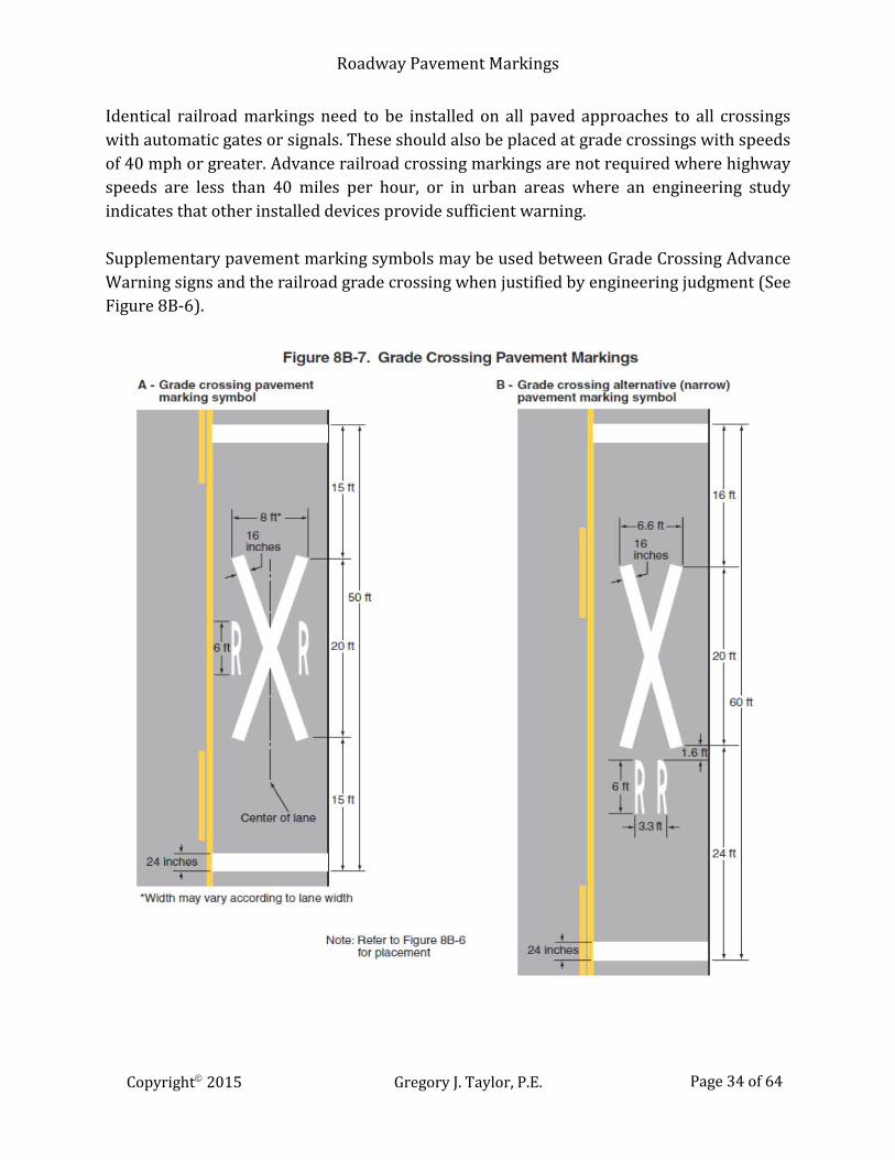
Identical railroad markings need to be installed on all paved approaches to all crossings with automatic gates or signals. These should also be placed at grade crossings with speeds of 40 mph or greater. Advance railroad crossing markings are not required where highway speeds are less than 40 miles per hour, or in urban areas where an engineering study indicates that other installed devices provide sufficient warning. Supplementary pavement marking symbols may be used between Grade Crossing Advance Warning signs and the railroad grade crossing when justified by engineering judgment (See Figure 8B-6).
Copyright 2015 Gregory J. Taylor, P.E. Page 34 of 64

Roadway Pavement Markings
A stop line is required for paved grade crossings equipped with active control devices (signals or gates). These are solid white lines across the approach lanes to indicate where a stop is required. A stop line should be placed a minimum distance of 15 feet before the nearest rail (8 feet in advance of any gates). A yield line may be used at passive grade crossing locations where a yield sign is used with a RR Crossbuck sign. These markings are a row of white isosceles triangles extended across approach lanes and aimed at approaching vehicles to indicate where a yield is intended. Yield markings should be installed similarly to stop line methods (15 feet from the nearest rail).
Copyright 2015 Gregory J. Taylor, P.E. Page 35 of 64
Roadway Pavement Markings
ROUNDABOUT MARKINGS Modern roundabouts are specific circular intersections designed for safety and speed control with specific traffic control features. Any design involving pavement markings should be integrated with the location and intended purpose of a roundabout. Pavement markings are used to delineate travel paths within roundabouts (entrances, exits, circulatory roadway, etc.) and provide guidance for the user. Markings on the roundabout’s approaches and circular roadway should provide a consistent message to road users. They should enhance vehicle movement with minimal lane changes in order to exit the roundabout.
APPROACH & DEPARTURE PAVEMENT MARKINGS Lane Lines Edge Lines Lane-Use Arrows Word and Symbol Markings Yield Lines Crosswalk Markings
Multi-lane roundabouts need to have lane line markings on the approaching roadways as well as within the circulatory roadway to channelize traffic to the appropriate exit. There are no continuous concentric lane lines within the roundabout’s circulatory roadway.
Copyright 2015 Gregory J. Taylor, P.E. Page 36 of 64
Roadway Pavement Markings
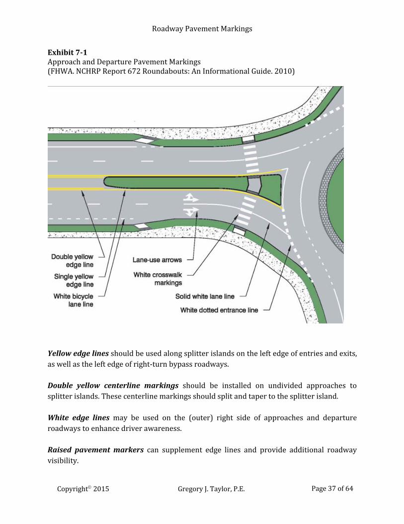
Exhibit 7-1 Approach and Departure Pavement Markings (FHWA. NCHRP Report 672 Roundabouts: An Informational Guide. 2010)
Yellow edge lines should be used along splitter islands on the left edge of entries and exits, as well as the left edge of right-turn bypass roadways. Double yellow centerline markings should be installed on undivided approaches to splitter islands. These centerline markings should split and taper to the splitter island. White edge lines may be used on the (outer) right side of approaches and departure roadways to enhance driver awareness. Raised pavement markers can supplement edge lines and provide additional roadway visibility.
Copyright 2015 Gregory J. Taylor, P.E. Page 37 of 64
Roadway Pavement Markings
White lane lines should be used on multilane approaches and departures to discourage lane changes in the immediate roundabout vicinity. White channelizing lines are used on approaches and departures for right-turn bypass islands with traffic on both sides. Bike lane lines on roundabout approaches should end in advance of the circulatory roadway (at beginning of taper and a minimum of 100 ft from the roadway’s edge). The last 50 to 200 ft of these lines should be dotted to provide advance warning of required merging maneuvers. Lane-use arrows are crucial at roundabouts for directing users to their appropriate lane. These markings should be installed at approaches with double left-turn or double right-turn lanes as well as at other locations to improve lane utilization. The arrows should be installed far enough in advance of the roundabout to give users adequate selection time for their path of travel. These markings may be repeated to encourage proper approach lane selection. Left-turn arrows should be included wherever lane-use arrows are used on approaches. This pavement marking combination will encourage proper lane use by drivers. Pavement Word and Symbol Markings ONLY word marking
May be used with lane-use arrows in single movement lanes Route numbers, destinations, street names, directions May be used with lane-use arrows, lane-use signs, and guide signs
(examples: NORTH, EAST, HWY 58, I-75, US 411) Yield Ahead symbol or word marking Can be used on approaches to supplement Yield Ahead sign YIELD word marking May be used at entries with Yield sign for additional yield emphasis Dotted circulatory edge lines should be used as entrance lines across roundabout entrance lanes to emphasize the border between entry and circulating traffic.
Copyright 2015 Gregory J. Taylor, P.E. Page 38 of 64

Roadway Pavement Markings
Yield lines consist of a series of white solid triangles (“shark teeth”) pointing toward approaching traffic. These markings (placed at right angles to the roadway) can be used to supplement entrance lines and enhance yielding requirements. Crosswalk markings for pedestrians should be used at all crossing locations (entries, exits, right-turn bypasses) for roundabouts. These crosswalks should be a minimum of 20 feet from the edge of the circulatory roadway. Longitudinal crosswalk markings (“zebra” or “continental”) are preferred. Their advantages include: better visibility; less user confusion; and less maintenance.
CIRCULATORY ROADWAY PAVEMENT MARKINGS Lane Lines Edge Lines Lane-Use Arrows
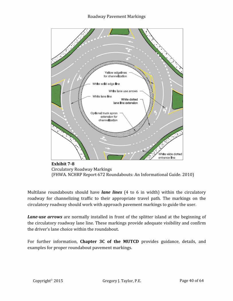
Yellow edge lines (4 to 6 in width) may be used along the circulatory road’s inside edge (central island or truck apron). These markings can be used with lane lines for channelizing traffic to appropriate roadway lanes. White edge lines (normal width) are to be installed on the circulatory roadway’s outer edge. White dotted edge line extensions (12 to 18 in width) across roundabout entries have a typical marking pattern of 2 ft lines with 2 to 3 ft gaps.
Copyright 2015 Gregory J. Taylor, P.E. Page 39 of 64
Roadway Pavement Markings
Exhibit 7-8 Circulatory Roadway Markings (FHWA. NCHRP Report 672 Roundabouts: An Informational Guide. 2010)
Multilane roundabouts should have lane lines (4 to 6 in width) within the circulatory roadway for channelizing traffic to their appropriate travel path. The markings on the circulatory roadway should work with approach pavement markings to guide the user. Lane-use arrows are normally installed in front of the splitter island at the beginning of the circulatory roadway lane line. These markings provide adequate visibility and confirm the driver’s lane choice within the roundabout. For further information, Chapter 3C of the MUTCD provides guidance, details, and examples for proper roundabout pavement markings.
Copyright 2015 Gregory J. Taylor, P.E. Page 40 of 64

Roadway Pavement Markings
PREFERENTIAL LANES Preferential lanes are those designated for special use – bicycles, toll lanes, taxis, high-occupancy vehicles (HOVs), light rail, etc. Different treatments may range from lane restrictions during peak time periods to providing separate roadway systems. Preferential lanes may operate in a constant direction or as reversible lanes. They may allow continuous access or restrict access to only specific locations. Preferential lane usage may also vary due to time – 24-hour basis, special events, peak travel periods, extended time periods, etc. All word and symbols markings for preferential lanes should be white and centered in the lane. For preferential lanes contiguous or separated by flush barriers from general purpose lanes, the following word or symbol pavement markings may be used: HOV lane – diamond shape symbol (2.5 ft minimum width, 12 ft length, 6 inch min.
lines) or word message HOV HOT lane or ETC Account-Only lane – word marking of ETC payment required for
lane (i.e. E-Z PASS ONLY) Bicycle lane – bicycle symbol or word marking BIKE LANE Bus only lane – word marking BUS ONLY Taxi only lane – word marking TAXI ONLY Light rail transit lane – word marking LRT ONLY Other types of preferential lanes – word marking appropriate for the restriction
The spacing of preferential lane markings should be based on engineering judgment and consider factors such as: block lengths prevailing speed distance to intersections road user communication
Spacings of 80 feet between markings might be suitable for suitable for local streets with 1000 feet spacing for freeways. The design and level of usage for preferential lanes determine their form: barrier-separated; buffer-separated; and contiguous.
Copyright 2015 Gregory J. Taylor, P.E. Page 41 of 64

Roadway Pavement Markings
Chevron markings (spaced at a minimum of 100 feet) may be used in buffer areas where preferential lanes and travel lanes are separated by buffers wider than 4 feet that are prohibited from vehicle crossings.
Copyright 2015 Gregory J. Taylor, P.E. Page 42 of 64

Roadway Pavement Markings
TOLL PLAZAS Toll plazas usually consist of toll booths, toll islands, toll lanes, and canopies where tolls are collected. Plazas located on highway mainlines are sometimes referred to as “barrier” toll plazas since they interrupt traffic flow.
Functions of Toll Plaza Pavement Markings Identify proper payment lanes Channelize lane movements Delineate roadway obstructions
Electronic Toll Collection (ETC) Account-Only lanes are non-attended toll lanes that are restricted to vehicles with registered toll payment accounts. Open-Road Tolling (ORT) systems are typically managed lanes that allow electronic toll collection from vehicles traveling at normal highway speeds. When one or more ORT lanes is limited to only registered ETC vehicles that bypass a mainline toll plaza on a separate alignment, word markings and longitudinal markings are used on the approach where the ORT lanes diverge from the mainline toll plaza lanes. At locations where ORT lanes are immediately adjacent to a mainline toll plaza but not separated by curbs or barriers from adjacent cash payment toll plaza lanes, channelizing devices, and/or pavement markings should be used to prevent lane changing. The ORT lane separation from the adjacent cash payment lane should start on the approach to the mainline toll plaza where vehicle speeds in the adjacent cash lanes drop below 30 mph during off-peak periods, and should extend downstream to where the departing vehicles in the adjacent cash lanes have accelerated to 30 mph. ETC Account-Only lane word markings and preferential lane longitudinal markings should be used for toll plaza approach lanes that are restricted to registered ETC vehicles. The lane lines or edge lines on the sides of the ETC Account-Only lane may be supplemented with purple solid contiguous longitudinal markings placed to the inside edges of the lane lines. These purple markings should have a minimum width of 3 inches with a maximum width equal to the line it supplements. Toll booths and their islands are considered to be obstructions that need appropriate markings that comply with these conditions. Longitudinal pavement markings do not have to be used alongside toll booth islands between the approach and departure markings.
Copyright 2015 Gregory J. Taylor, P.E. Page 43 of 64
Roadway Pavement Markings
DELINEATORS Delineators are retroreflective devices that are mounted on either the roadway surface or at the roadside in a series to highlight the roadway’s alignment, especially at night or inclement weather. These guidance devices are extremely effective at locations with unexpected or confusing elements (curves, lane transitions, etc.). Visibility is the key advantage of delineators for wet or snow-covered roadways. They are also suitable for long continuous roadway sections or short stretches with changes in horizontal alignment. Design Delineators are made up of retroreflective elements (minimum of 3 inches) that retroreflect light from a distance of 1,000 feet when illuminated by automobile high beam headlights.
Single delineators: One retroreflective element for a given direction of travel at a specific location Double delineator*: Two identical retroreflective elements mounted together for a direction *An appropriately sized vertically elongated delineator may be used in lieu of a double delineator.
Application A series of single delineators shall be used on the right side of freeways and expressways and on one side of interchange ramps, except when either of the following conditions are met:
1) On tangent sections of freeways and expressways when both of the following conditions are met:
a. Continuous raised pavement markers are used to supplement pavement markings on lane lines throughout all curves and on all tangents, and
b. Roadside delineators are used to direct traffic into all curves.
2) On sections of roadways with continuous lighting between interchanges.
Delineators are also suitable for other classes of roads. Plus, a series of single delineators may be used as needed on the left-hand side of roadways.
Copyright 2015 Gregory J. Taylor, P.E. Page 44 of 64

Roadway Pavement Markings
Delineator colors should comply with those used for the edge line. These devices may be used to indicate where either an outside or inside traffic lane merges into an adjacent lane. Delineators should also be placed adjacent to the lane reduced for the full transition length and highlight the reduction.
Delineator Colors White: Left-hand side of a two-way roadway Red: Wrong direction of ramp or roadway
Truck escape ramp Red delineators can be used on the reverse side of any delineator to warn road users traveling in the wrong direction on a particular ramp or roadway. This color should also be used on both sides of truck escape ramps - spaced at 50-foot intervals to identify the ramp entrance. Spacing beyond the entrance should be appropriate for the escape ramp’s length and design. Placement and Spacing Delineators should be mounted at a height of approximately 4 feet (measured vertically from the bottom of the device to the elevation of the edge of the roadway). They may be mounted at a lower elevation when placed on the face or top of guardrails or other barriers.
Delineator Installation Example
(TDOT)
Copyright 2015 Gregory J. Taylor, P.E. Page 45 of 64

Roadway Pavement Markings
Delineators should be placed at a constant distance from the edge of roadway 2 to 8 feet outside the outer shoulder edge, or in line with roadside barriers that are a maximum distance of 8 feet outside the outer shoulder edge. For locations where an obstruction is between the pavement edge and the line of the delineators, the delineators should be transitioned to the innermost edge of the obstruction. Delineators for guardrail or other longitudinal barrier (if considered to be an obstruction) should be transitioned just behind, directly above, or on the barrier’s innermost edge.
Delineator Angle Example (TDOT)
Delineator spacing should be adjusted throughout horizontal curves to ensure that several are always visible to the driver. These devices may be mounted closely-spaced on guardrails or other longitudinal barriers to form a continuous or nearly continuous flow of delineation where needed. Delineators should be spaced 200 to 530 feet apart on mainline tangent sections and 100 feet apart on ramp tangent sections.
Copyright 2015 Gregory J. Taylor, P.E. Page 46 of 64

Roadway Pavement Markings
Double or vertically elongated delineators should be placed at 100-foot intervals for acceleration and deceleration lanes.
Copyright 2015 Gregory J. Taylor, P.E. Page 47 of 64

Roadway Pavement Markings
Copyright 2015 Gregory J. Taylor, P.E. Page 48 of 64
Roadway Pavement Markings
Other Delineator Placement
Interchange Ramps: Series of single delineators on outside curves Median Cross-overs: Double yellow delineator on left side of through
roadway on far side of crossover for each road Highways: Delineators carried through transitions closely (continuous delineation) spaced
COLORED PAVEMENTS Colored paving consists of various paving materials (asphalt or concrete) or marking materials that simulate colored pavement. If the colored pavement is non-retroreflective (brick or patterned surface) and used for aesthetics (not regulatory, warning, or guidance purposes), it is not considered to be a traffic control device – and not subject to specific colors or applications. However, if the colored pavement is used:
within the traveled way, on flush or raised islands, or on shoulders
for regulating, warning, or guiding traffic – or if its retroreflective, then the pavement is considered to be a traffic control device. When used in this manner, colored paving should be used only where they contrast with adjoining pavement. These are limited to specific colors and uses that must be applicable at all times.
Yellow: flush or raised median islands separating traffic in opposite directions left-hand roadway shoulders for divided highways, one-way streets, or ramps
White: flush or raised channelizing islands where traffic passes on both sides in
the same direction right-hand shoulders The FHWA has also approved the optional use of green colored pavement for marked bicycle lanes and facilities.
Copyright 2015 Gregory J. Taylor, P.E. Page 49 of 64
Roadway Pavement Markings
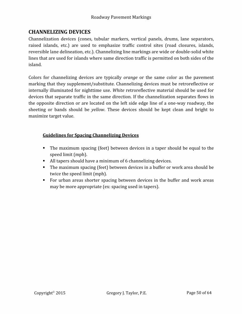
CHANNELIZING DEVICES Channelization devices (cones, tubular markers, vertical panels, drums, lane separators, raised islands, etc.) are used to emphasize traffic control sites (road closures, islands, reversible lane delineation, etc.). Channelizing line markings are wide or double-solid white lines that are used for islands where same direction traffic is permitted on both sides of the island. Colors for channelizing devices are typically orange or the same color as the pavement marking that they supplement/substitute. Channelizing devices must be retroreflective or internally illuminated for nighttime use. White retroreflective material should be used for devices that separate traffic in the same direction. If the channelization separates flows in the opposite direction or are located on the left side edge line of a one-way roadway, the sheeting or bands should be yellow. These devices should be kept clean and bright to maximize target value.
Guidelines for Spacing Channelizing Devices The maximum spacing (feet) between devices in a taper should be equal to the
speed limit (mph). All tapers should have a minimum of 6 channelizing devices. The maximum spacing (feet) between devices in a buffer or work area should be
twice the speed limit (mph). For urban areas shorter spacing between devices in the buffer and work areas
may be more appropriate (ex: spacing used in tapers).
Copyright 2015 Gregory J. Taylor, P.E. Page 50 of 64

Roadway Pavement Markings
Copyright 2015 Gregory J. Taylor, P.E. Page 51 of 64
Roadway Pavement Markings
TRAFFIC ISLANDS A traffic island is a defined space between traffic lanes for controlling vehicular movement. These areas include all end protection and approach treatments. A median or an outer separation within an intersection area is considered to be an island.
Purposes of Traffic Islands Separating conflicts Controlling conflict angles Reducing excessive pavement Regulating traffic Turning movements at intersections Protecting pedestrians Traffic control devices
Traffic islands can be designated by curbs, pavement edges, pavement markings, channelizing devices, or other devices. Curbed or painted islands that are used to control and direct traffic are generally appropriate for locations with heavy through-traffic and turning movements. Islands can also be used to alert and regulate drivers through upcoming intersections (left-turning traffic, right-turn channels, etc.). Divergent longitudinal pavement markings should precede the approach ends of the traffic island in order to guide motorists along the island’s edge. Rumble sections may be used to discourage driving in the neutral area between approach-end markings. These sections usually contain slightly raised (1-inch high maximum) sections of coarse aggregate, etc. to increase visibility and produce audible warnings. Additional techniques may include raised bars or buttons (1 to 3 inches above the roadway surface) to better designate the island area. These measures are designed to warn the driver with only minimal effects on the control of the vehicle. Raised bars or buttons should be marked with white or yellow retroreflective materials, as determined by the direction or directions of travel they separate. Channelizing devices used in advance of islands with raised curbs should not be placed in such a manner that creates an unexpected obstacle.
Copyright 2015 Gregory J. Taylor, P.E. Page 52 of 64
Roadway Pavement Markings
Traffic Island Markings Pavement markings Curb markings Channelizing devices Delineators
Pavement markings for the approach to an obstruction may be omitted on a particular island if it is deemed necessary by engineering judgment. Colors Retroreflective white or yellow material should be used to mark islands outlined by curbs or pavement markings. These need to be long enough to indicate the general alignment of the island’s edge along which vehicles travel – including the approach end. Curb retroreflection may be discontinued along the entire length for long traffic islands – especially if illuminated, delineated or marked with edge lines. Islands delineators should be the same colors as the related edge lines. The only exception is for red delineators that are used for wrong-way traffic. Each roadway approach through an intersection is to be considered separately to assure maximum effectiveness when using delineators. Appropriately colored retroreflective or internally illuminated markers may be placed in front of the curb and/or on the top of curbed approaches of raised medians and curbs of islands to supplement or substitute for retroreflective curb markings. Pedestrian Islands and Medians Raised islands or medians in the center area of a roadway can serve as pedestrian refuge island for those attempting to cross at midblock or intersection locations. These areas allow pedestrians to find an adequate gap in one direction of traffic and then wait for an adequate gap in the other direction before crossing the second half of the road. Pedestrian refuges are typically used at wide crossing streets or transit stops. These are generally near crosswalks or bike crossings and should have a minimum width of 6 feet.
Copyright 2015 Gregory J. Taylor, P.E. Page 53 of 64

Roadway Pavement Markings
Traffic Island Areas Urban Areas: 50 ft² minimum Rural Areas: 75 ft² minimum Desirable*: 100ft² minimum
*For accommodating non-motorized users and traffic control devices Design guidelines for islands are specified in A Policy on Geometric Design of Highways and Streets (AASHTO “Green Book”). The Americans with Disabilities Act Accessibility Guidelines for Buildings and Facilities (ADAAG) provides the minimum widths for accessible refuge islands plus the design and placement of detectable warning surfaces.
Copyright 2015 Gregory J. Taylor, P.E. Page 54 of 64

Roadway Pavement Markings
Example Traffic Island Pavement Markings
(TDOT)
Copyright 2015 Gregory J. Taylor, P.E. Page 55 of 64
Roadway Pavement Markings
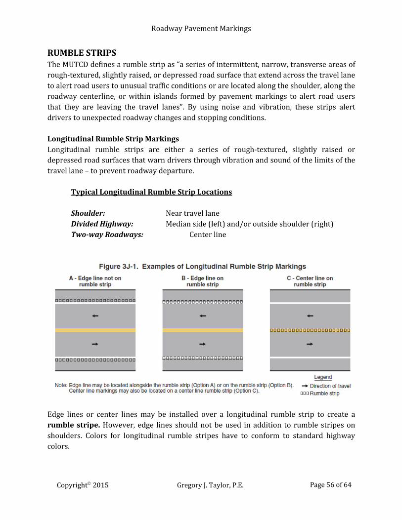
RUMBLE STRIPS The MUTCD defines a rumble strip as “a series of intermittent, narrow, transverse areas of rough-textured, slightly raised, or depressed road surface that extend across the travel lane to alert road users to unusual traffic conditions or are located along the shoulder, along the roadway centerline, or within islands formed by pavement markings to alert road users that they are leaving the travel lanes”. By using noise and vibration, these strips alert drivers to unexpected roadway changes and stopping conditions. Longitudinal Rumble Strip Markings Longitudinal rumble strips are either a series of rough-textured, slightly raised or depressed road surfaces that warn drivers through vibration and sound of the limits of the travel lane – to prevent roadway departure.
Typical Longitudinal Rumble Strip Locations Shoulder: Near travel lane Divided Highway: Median side (left) and/or outside shoulder (right) Two-way Roadways: Center line
Edge lines or center lines may be installed over a longitudinal rumble strip to create a rumble stripe. However, edge lines should not be used in addition to rumble stripes on shoulders. Colors for longitudinal rumble stripes have to conform to standard highway colors.
Copyright 2015 Gregory J. Taylor, P.E. Page 56 of 64
Roadway Pavement Markings
Transverse Rumble Strip Markings Transverse rumble strips are intermittent narrow, transverse areas of roughly textured, slightly raised or depressed road surface that extend across the travel lanes. The resulting noise and vibration warns the driver about unusual vehicular traffic conditions (i.e. unexpected changes in road alignment, stopping conditions, speed reduction). For locations where the color of a transverse rumble strip within a travel lane does not match the color of the pavement, the strip will be either black or white. To avoid confusion, white transverse rumble strips should not be placed in locations with other transverse markings (stop lines, crosswalks, etc.). SCHOOL MARKINGS Pavement markings play an important role in school area traffic control. They can be used alone as an effective method for conveying regulations, guidance, and warnings that otherwise may not be expressed by other devices. Markings can also be used to supplement regulatory or warning devices (signs signals, etc.). In any case, school markings serve definite and important functions in the arena of traffic control devices.
Pavement Marking Limitations Low visibility due to inclement weather Lack of durability in heavy traffic areas
The main advantage of these pavement markings is their ability to convey information to the road user without diverting attention from the roadway. Crosswalk Markings Crosswalks should be marked at all intersections on established school routes
where there is substantial conflict between motorists, bicyclists, and student movements;
where students are encouraged to cross between intersections; where students would not otherwise recognize the proper place to cross; or where motorists or bicyclists might not expect students to cross.
Crosswalk lines should never be placed at any location indiscriminately; an engineering study should be conducted before installing a marked crosswalk away from a traffic control signal or an approach controlled by a STOP or YIELD sign.
Copyright 2015 Gregory J. Taylor, P.E. Page 57 of 64
Roadway Pavement Markings
Warning signs should be installed for all marked school crosswalks at non-intersection school crossings, since these are generally unexpected by the motorist. Adequate visibility of students by approaching vehicles should be maintained by parking restrictions or other measures.
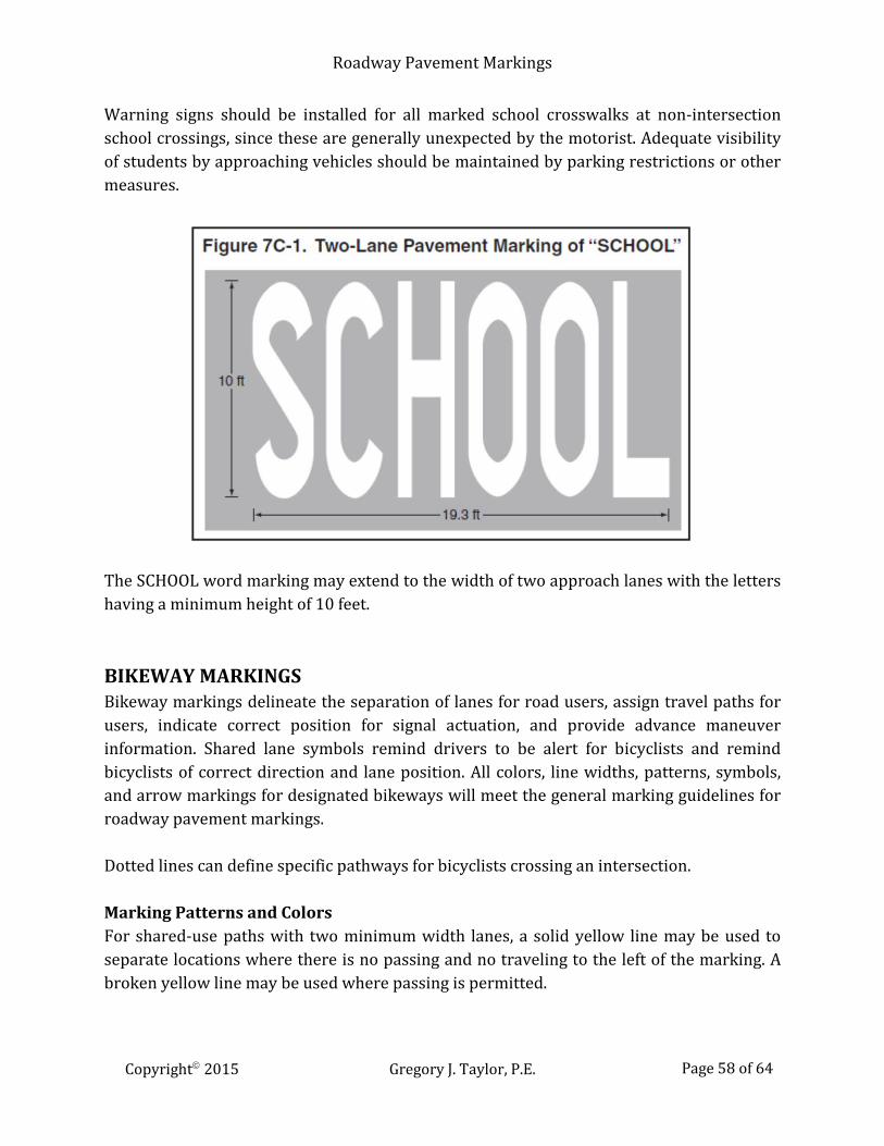
The SCHOOL word marking may extend to the width of two approach lanes with the letters having a minimum height of 10 feet. BIKEWAY MARKINGS Bikeway markings delineate the separation of lanes for road users, assign travel paths for users, indicate correct position for signal actuation, and provide advance maneuver information. Shared lane symbols remind drivers to be alert for bicyclists and remind bicyclists of correct direction and lane position. All colors, line widths, patterns, symbols, and arrow markings for designated bikeways will meet the general marking guidelines for roadway pavement markings. Dotted lines can define specific pathways for bicyclists crossing an intersection. Marking Patterns and Colors For shared-use paths with two minimum width lanes, a solid yellow line may be used to separate locations where there is no passing and no traveling to the left of the marking. A broken yellow line may be used where passing is permitted.
Copyright 2015 Gregory J. Taylor, P.E. Page 58 of 64
Roadway Pavement Markings
Broken lines on shared-use paths should have the usual 1-to-3 segment-to-gap ratio (3-foot segment with a 9-foot gap). A solid white line may be used to separate different types of shared-use path users - the Shared-Use Path Restriction (R9-7) sign may be used as a supplement. Smaller scale letters and symbols are appropriate for use on shared-use paths. Bicycle Lane Markings Pavement markings indicate roadway sections for preferential use by bicyclists. Longitudinal pavement markings define bicycle lanes, inform all road users of restrictions, and should be retroreflectorized. The bicycle lane word, symbol, and/or arrow markings (see Figure 9C-3) should be placed at the beginning of a bicycle lane and at periodic intervals along the bicycle lane based on engineering judgment. For locations where the bicycle lane symbol marking is used in conjunction with word or arrow messages, it should precede them. Pavement marking materials should be used that will minimize traction loss for bicycles under wet conditions. When using bicycle lane word, symbol, or arrow markings, Bike Lane signs may also be installed.
Copyright 2015 Gregory J. Taylor, P.E. Page 59 of 64

Roadway Pavement Markings
For locations where a right through lane is dropped to become a right turn only lane, bicycle lane markings should stop a minimum distance of 100 feet before the beginning of the right-turn lane. Through bicycle lane markings are to continue to the left of the right turn only lane. Posts or raised pavement markers should never be used for separating bicycle lanes and adjacent travel lanes. Any raised devices create a potential for bicycle crashes by placing fixed objects immediately adjacent to the travel path of the cyclist. These devices can prevent right-turning vehicles from merging with the bicycle lane - the preferred method for making the right turn. Raised devices can also cause cleaning and maintenance problems for the bicycle lane.
Copyright 2015 Gregory J. Taylor, P.E. Page 60 of 64
Roadway Pavement Markings
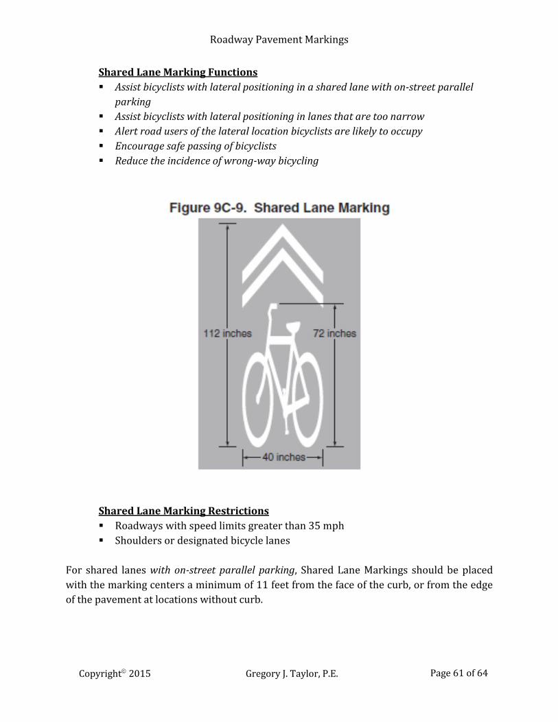
Shared Lane Marking Functions Assist bicyclists with lateral positioning in a shared lane with on-street parallel
parking Assist bicyclists with lateral positioning in lanes that are too narrow Alert road users of the lateral location bicyclists are likely to occupy Encourage safe passing of bicyclists Reduce the incidence of wrong-way bicycling
Shared Lane Marking Restrictions Roadways with speed limits greater than 35 mph Shoulders or designated bicycle lanes
For shared lanes with on-street parallel parking, Shared Lane Markings should be placed with the marking centers a minimum of 11 feet from the face of the curb, or from the edge of the pavement at locations without curb.
Copyright 2015 Gregory J. Taylor, P.E. Page 61 of 64
Roadway Pavement Markings
On streets without on-street parking with an outside travel lane less than 14 feet wide, the centers of the markings should be a minimum of 4 feet from the curb face, or from the edge of the pavement without curb. The Shared Lane Marking may be placed immediately after an intersection and spaced at a maximum distance of 250 feet thereafter. A Bicycles May Use Full Lane (R4-11) sign that may be used to supplement or substitute for the Shared Lane Marking to inform motorists of bicyclists that might occupy the travel lane. MAINTENANCE ISSUES Pavement markings should be inspected periodically to ensure that they are meeting their intended purpose. Pavement markings (thermoplastic, epoxy, or tape) should be replaced as required or recommended by the manufacturer. Painted markings have shorter life spans and should be considered for repainting annually or when necessary. Markings that are no longer applicable need to be removed or obliterated to be unidentifiable. Roadway pavement markings need to be retroreflective unless there is sufficient ambient illumination. All interstate or highway markings should be retroreflective. An up-to-date inventory of pavement markings is essential for proper maintenance. It provides a record of the existing markings, and will also aid in estimating replacement marking quantities. Inspections should be conducted during daylight and night hours (as well as wet road conditions) to evaluate the marking’s visibility and retroreflectivity. Any water can severely affect retroreflectivity by making tarred joints and sealed cracks appear more dominant than the striping. Bright sunlight at low angles (sunrise and sunset) can also produce this effect.
Copyright 2015 Gregory J. Taylor, P.E. Page 62 of 64
Roadway Pavement Markings
SUMMARY Roadway pavement markings are critical tools that convey regulations, traffic, roadway conditions, and other important information. These allow users to travel safely on any U.S. roadway. The goal of traffic control is to provide drivers with relevant information when they need it. The overall objective of this course was to give engineers and designers an in-depth look at pavement marking selection and design principles. The Manual on Uniform Traffic Control Devices for Streets and Highways (MUTCD) 2009 Edition was used to explain the fundamental design principles of markings. This text is the recognized national standard for all traffic control devices installed on any road or bikeway. The contents of this course were intended to serve as guidance and not as an absolute rule. It was written to help you learn to use the MUTCD more effectively for establishing roadway traffic control using pavement markings. This course discusses how to effectively use pavement markings to guide roadway traffic, and thereby reduce your liability exposure. The contents of this course are intended to serve as guidance and not as an absolute standard or rule. Its purpose is to help you to use the Manual on Uniform Traffic Control Devices (MUTCD) – Parts 3, 5, 7, 8 and 9 more effectively and not replace it. Should there be any discrepancies between the contents of this course and the MUTCD - always follow the MUTCD. Upon course completion, you should be familiar with the general design guidelines for pavement markings. The course objective is to give engineers and designers an in-depth look at the principles to be considered when selecting and designing for traffic control.
Copyright 2015 Gregory J. Taylor, P.E. Page 63 of 64

Roadway Pavement Markings
REFERENCES A Policy on Geometric Design of Highways and Streets, 2004 Edition, American Association of State Highway and Transportation Officials (AASHTO) Highway Capacity Manual, 2000 Edition, Transportation Research Board, Washington, DC Manual on Uniform Traffic Control Devices, 2009 Edition, Federal Highway Administration, Washington, DC (Note: All figures, tables, exhibits, etc. contained in this course are from this text – unless otherwise noted) Standard Roadway Drawings, Tennessee Department of Transportation Roadside Design Guide, 2006 Edition, American Association of State Highway and Transportation Officials (AASHTO) Standard Highway Signs Book, 2004 Edition, Federal Highway Administration, Washington, DC Sign Retroreflectivity Guidebook, Federal Highway Administration, Washington, DC, 2009 Traffic Engineering Handbook, 6th Edition, Institute of Traffic Engineers, Washington, DC, 2008 Traffic Control Devices Handbook, 2001, Institute of Traffic Engineers, Washington, DC Traffic Signs and Pavement Markings, Cornell Local Roads Program, Ithaca, NY, 2008 United States Pavement Markings, USDOT, Federal Highway Administration, Washington, DC, 2002
Copyright 2015 Gregory J. Taylor, P.E. Page 64 of 64