multimedia projector - cncms.com.aucncms.com.au/sanyo-ims/commercial-industrial/plcxe40_im.pdf ·...
TRANSCRIPT

Multimedia Projector
MODEL PLC-XE40
Owner’s Manual

2
Features and Design
◆ Large Screen in Limited Space
- Short focus lens allows you to project large imagesfrom short distance. (p. 14)
◆ Antitheft Alarm Function
This projector is equipped with an Antitheft alarmfunction which sounds when a vibration is detected.(pp. 48, 50 - 52)
◆ Security Features
- The projector cannot be operated without remotecontrol. Keep the remote control securely at handto minimize the risk of theft.
- Easily identifiable orange cabinet for security.
- The PIN cord lock guards the projector from anunauthorized user. (pp. 19, 47, 48).
◆ Logo Function
The Logo function allows you to customize thescreen logo. The Logo page identifies the owner ofthe projector. (pp. 43, 44)
◆ Compact Design
This projector is designed to be compact in size andweight. It is easy to carry and work anywhere youwant to use.
◆ Simple Computer System Setting
The projector has a Multi-scan system to conform toalmost all computer output signals quickly. (p. 27)
◆ Compatibility
The projector widely accepts various video andcomputer input signals including; Computers, 6 Colorsystems (PAL, SECAM, NTSC, NTSC4.43, PAL-M, orPAL-N), Component video, S-Video and RGB scart.
◆ Quick Termination
The AC power cord can be unplugged immediatelyafter turning off the projector without waiting for theprojector to cool down. (p. 20)
◆ Digital Zoom (for Computer)
The digital zoom function allows you to focus on crucialinformation during a presentation. You can expand theimages approx. 16 times the screen size and compressthem to approx. half of the screen size. (p. 34)
◆ Blackboard Function
A blackboard✳ can be used as a projection screen. (pp. 31, 38)
✳ The board color is limited to Green.
◆ Multilanguage Menu Display
The Operation menu is available in 16 languages;English, German, French, Ital ian, Spanish,Portuguese, Dutch, Swedish, Finnish, Polish,Hungarian, Romanian, Russian, Chinese, Korean, orJapanese. (p. 42)
◆ Switchable Interface Terminal
The projector provides a switchable interfaceterminal. You can user the terminal as computerinput or monitor output conveniently. (p45)
◆ Power Management
The Power management function reduces powerconsumption and maintains lamp life. (p. 45)
This Multimedia Projector is designed with the most advanced technology for portability, durability, and ease of use.This projector utilizes built-in multimedia features, a palette of 16.77 million colors, and matrix liquid crystal display(LCD) technology.
✔Note:• The On-Screen Menu and figures in this manual may differ slightly from the product.
• The contents of this manual are subject to change without notice.
You can turn on or operate the projector ONLY
via the remote control. Make sure not to lose
the remote control.

3
Table of Contents
TrademarksEach name of corporations or products in this book is either a registered trademark or a trademark of its respectivecorporation.
Features and Design . . . . . . . . . . . . . . . . . . .2
Table of Contents . . . . . . . . . . . . . . . . . . . . . .3
To the Owner . . . . . . . . . . . . . . . . . . . . . . . . .4
Safety Instructions . . . . . . . . . . . . . . . . . . . .5
Air Circulation 6Installing the Projector in Proper Position 6Moving the Projector 6
Compliance . . . . . . . . . . . . . . . . . . . . . . . . . .7
Part Names and Functions . . . . . . . . . . . . . .8
Front 8Back 8Bottom 8Rear Terminal 9Top Control 10Antitheft Alarm Setting Buttons 11Remote Control 12Remote Control Battery Installation 13Operating Range 13
Installation . . . . . . . . . . . . . . . . . . . . . . . . . .14
Positioning the Projector 14Adjustable Feet 14Connecting the AC Power Cord 15Connecting to a Computer 16Connecting to Video Equipment 17Connecting to Component Video Equipment 18
Basic Operation . . . . . . . . . . . . . . . . . . . . . .19
Turning On the Projector 19Turning Off the Projector 20How to Operate the On-Screen Menu 21Menu Bar 22Focus Adjustment 23Keystone Correction 23Sound Adjustment 24Remote Control Operation 24
Computer Input . . . . . . . . . . . . . . . . . . . . .26
Input Source Selection 26Computer System Selection 27Auto PC Adjustment 28Manual PC Adjustment 29Image Level Selection 31Image Level Adjustment 32Screen Size Adjustment 33
Video Input . . . . . . . . . . . . . . . . . . . . . . . . . .35
Input Source Selection (Video, S-Video) 35Input Source Selection(Component, RGB Scart 21-pin) 36
Video System Selection 37Image Level Selection 38Image Level Adjustment 39Screen Size Adjustment 41
Setting . . . . . . . . . . . . . . . . . . . . . . . . . . . . .42
Setting 42
Antitheft Alarm function . . . . . . . . . . . . . . .50
How to Use the Antitheft Alarm Function 50
Maintenance and Cleaning . . . . . . . . . . . . .53
Warning Indicator 53Cleaning the Air Filters 54Attaching the Lens Cover 54Cleaning the Projection Lens 55Cleaning the Projector Cabinet 55Lamp Replacement 56Lamp Replacement Counter 57
Appendix . . . . . . . . . . . . . . . . . . . . . . . . . . .58
Troubleshooting 58Menu Tree 60Indicators and Projector Condition 62Compatible Computer Specifications 63Technical Specifications 64Optional Parts 65Configurations of Terminals 66PIN Code Label 67

4
To the Owner
CAUTION : TO REDUCE THE RISK OF ELECTRIC
SHOCK, DO NOT REMOVE COVER (OR
BACK). NO USER-SERVICEABLE PARTS
INSIDE EXCEPT LAMP REPLACEMENT.
REFER SERVICING TO QUALIFIED
SERVICE PERSONNEL.
THIS SYMBOL INDICATES THAT DANGEROUSVOLTAGE CONSTITUTING A RISK OF ELECTRICSHOCK IS PRESENT WITHIN THIS UNIT.
THIS SYMBOL INDICATES THAT THERE AREIMPORTANT OPERATING AND MAINTENANCEINSTRUCTIONS IN THE OWNER'S MANUAL WITHTHIS UNIT.
CAUTION
RISK OF ELECTRIC SHOCK
DO NOT OPEN
Before operating this projector, read this manual thoroughly and operate the projector properly. This projector provides many convenient features and functions. Operating the projector properly enables you to manage those features and maintains it in better condition fora considerable time.Improper operation may result in not only shortening the product-life, but also malfunctions, fire hazard, or other accidents.If your projector seems to operate improperly, read this manual again, check operations and cable connections and try the solutions in the “Troubleshooting” section in the end of this booklet. If the problem still persists, contact the dealer where you purchased the projector or the service center.
Safety Precaution
WARNING : TO REDUCE THE RISK OF FIRE OR ELECTRIC
SHOCK, DO NOT EXPOSE THIS APPLIANCE
TO RAIN OR MOISTURE.
– This projector produces intense light from the projectionlens. Do not stare directly into the lens as much aspossible. Eye damage could result. Be especially carefulthat children do not stare directly into the beam.
– Install the projector in a proper position. If not, it mayresult in a fire hazard.
– Provide appropriate space on the top, sides and rear of theprojector cabinet for allowing air circulation and cooling theprojector. Minimum clearance must be maintained. If theprojector is to be built into a compartment or similarlyenclosed, the minimum distances must be maintained. Donot cover the ventilation slot on the projector. Heat build-up can reduce the service life of your projector, and canalso be dangerous.
– If the projector is not to be used for an extended time,unplug the projector from the power outlet.
0.7'(20cm)
1.5'(50cm) 3'(1m) 1.5'(50cm)
SIDE and TOP REAR
CAUTION
Not for use in a computer room as defined in the Standard for the Protection of Electronic Computer/Data Processing Equipment, ANSI/NFPA 75.
Ne peut être utilisé dans une salle d’ordinateurs telle que définie dans la norme ANSI/NFPA 75 Standard for Protection of Electronic Computer/Data Processing Equipment
NOTE: This symbol and recycle system are applied only to EU countries and not applied to the countries in the other area of the world.
Your SANYO product is designed andmanufactured with high qualitymaterials and components which can berecycled and reused.
This symbol means that electrical andelectronic equipment, at their end-of-life, should be disposed of separatelyfrom your household waste.
Please dispose of this equipment at your local communitywaste collection/recycling centre.In the European Union there are separate collectionsystems for used electrical and electronic products.
Please help us to conserve the environment we live in!
CAUTION ON HANGING FROM THE CEILING
When hanging the projector from theceiling, clean air intake vents, air fil-ters, or top of the projector periodical-ly with a vacuum cleaner. If you leavethe projector without cleaning for along time, the dust will block the oper-ation of the cooling function, and itmay cause a breakdown or a disaster.
DO NOT SET THE PROJECTOR IN GREASY, WET, OR
SMOKY CONDITIONS SUCH AS IN A KITCHEN TO PRE-
VENT A BREAKDOWN OR A DISASTER. IF THE
PROJECTOR COMES IN CONTACT WITH OIL OR CHEMI-
CALS, IT MAY BECOME DETERIORATED.
READ AND KEEP THIS OWNER'S MANUAL FOR LATER
USE.

5
Safety Instructions
All the safety and operating instructions should be read beforethe product is operated.
Read all of the instructions given here and retain them for lateruse. Unplug this projector from AC power supply beforecleaning. Do not use liquid or aerosol cleaners. Use a dampcloth for cleaning.
Follow all warnings and instructions marked on the projector.
For added protection to the projector during a lightning storm,or when it is left unattended and unused for long periods oftime, unplug it from the wall outlet. This will prevent damagedue to lightning and power line surges.
Do not expose this unit to rain or use near water... forexample, in a wet basement, near a swimming pool, etc...
Do not use attachments not recommended by themanufacturer as they may cause hazards.
Do not place this projector on an unstable cart, stand, or table.The projector may fall, causing serious injury to a child oradult, and serious damage to the projector. Use only with acart or stand recommended by the manufacturer, or sold withthe projector. Wall or shelf mounting should follow themanufacturer's instructions, and should use a mounting kitapproved by the manufacturers.
An appliance and cart combination shouldbe moved with care. Quick stops,excessive force, and uneven surfacesmay cause the appliance and cartcombination to overturn.
Slots and openings in the back and bottom of the cabinet areprovided for ventilation, to ensure reliable operation of theequipment and to protect it from overheating.
The openings should never be covered with cloth or othermaterials, and the bottom opening should not be blocked byplacing the projector on a bed, sofa, rug, or other similarsurface. This projector should never be placed near or over aradiator or heat register.
This projector should not be placed in a built-in installationsuch as a book case unless proper ventilation is provided.
Never push objects of any kind into this projector throughcabinet slots as they may touch dangerous voltage points orshort out parts that could result in a fire or electric shock.Never spill liquid of any kind on the projector.
Do not install the projector near the ventilation duct of air-conditioning equipment.
This projector should be operated only from the type of powersource indicated on the marking label. If you are not sure ofthe type of power supplied, consult your authorized dealer orlocal power company.
Do not overload wall outlets and extension cords as this canresult in fire or electric shock. Do not allow anything to reston the power cord. Do not locate this projector where thecord may be damaged by persons walking on it.
Do not attempt to service this projector yourself as opening orremoving covers may expose you to dangerous voltage orother hazards. Refer all servicing to qualified servicepersonnel.
Unplug this projector from wall outlet and refer servicing toqualified service personnel under the following conditions:a. When the power cord or plug is damaged or frayed.b. If liquid has been spilled into the projector.c. If the projector has been exposed to rain or water.d. If the projector does not operate normally by following the
operating instructions. Adjust only those controls that arecovered by the operating instructions as improperadjustment of other controls may result in damage and willoften require extensive work by a qualified technician torestore the projector to normal operation.
e. If the projector has been dropped or the cabinet has beendamaged.
f. When the projector exhibits a distinct change inperformance-this indicates a need for service.
When replacement parts are required, be sure the servicetechnician has used replacement parts specified by themanufacturer that have the same characteristics as theoriginal part. Unauthorized substitutions may result in fire,electric shock, or injury to persons.
Upon completion of any service or repairs to this projector,ask the service technician to perform routine safety checks todetermine that the projector is in safe operating condition.
Voor de klanten in Nederland
Bij dit produkt zi jn batteri jengeleverd. Wanneer deze leeg zijn, moet uze niet weggooien maar inleverenals KCA.NL

6
Safety Instructions
USE CAUTION IN CARRYING OR TRANSPORTING THE PROJECTOR
– Do not drop or bump the projector, otherwisedamages or malfunctions may result.
– When carrying the projector, use a suitable carryingcase.
– Do not transport the projector by using a courier ortransport service in an unsuitable transport case. Thismay cause damage to the projector. To transport theprojector through a courier or transport service, consultyour dealer for their information.
– Do not put the projector in a case before the projectoris cooled enough.
Moving the ProjectorWhen moving the projector, replace the lens cover andretract the adjustable feet to prevent damage to thelens and cabinet. When the projector is not in use foran extended period, put it into a suitable case to protectthe projector. When handling the projector, do not drop, bump,subject it to strong forces or put other things on thecabinet.
Do not tilt the projector more than20 degrees from side to side.
Do not point the projector up toproject an image.
Do not point the projector downto project an image.
Do not put the projector on eitherside to project an image.
Install the projector properly. Improper Installation mayreduce the lamp life and cause a fire hazard.
Installing the Projector in Proper Position
Openings in the cabinet are provided for ventilation andto ensure reliable operation of the product and toprotect it from overheating, and these openings mustnot be blocked or covered.
CAUTION
Hot air is exhausted from the exhaust vent. Whenusing or install ing the projector, the followingprecautions should be taken. –Do not put any flammable object or spray can near the
projector, hot air is exhausted from the ventilationholes.
–Keep the exhaust vent at least 3’(1m) away from anyobjects.
–Do not touch a peripheral part of the exhaust vent,especially screws and metallic part. This area willbecome hot while the projector is being used.
–Do not put anything on the cabinet. The materials puton the cabinet will not only get damaged but alsocause fire hazard by heat.
Cooling fans are provided to cool down the projector.The fans' running speed is changed according to thetemperature inside the projector.
Air Circulation
20˚
20˚
Air IntakeVent
Exhaust Vent(Hot air exhaust)
Exhaust Vent(Hot air exhaust)
Air IntakeVent
7
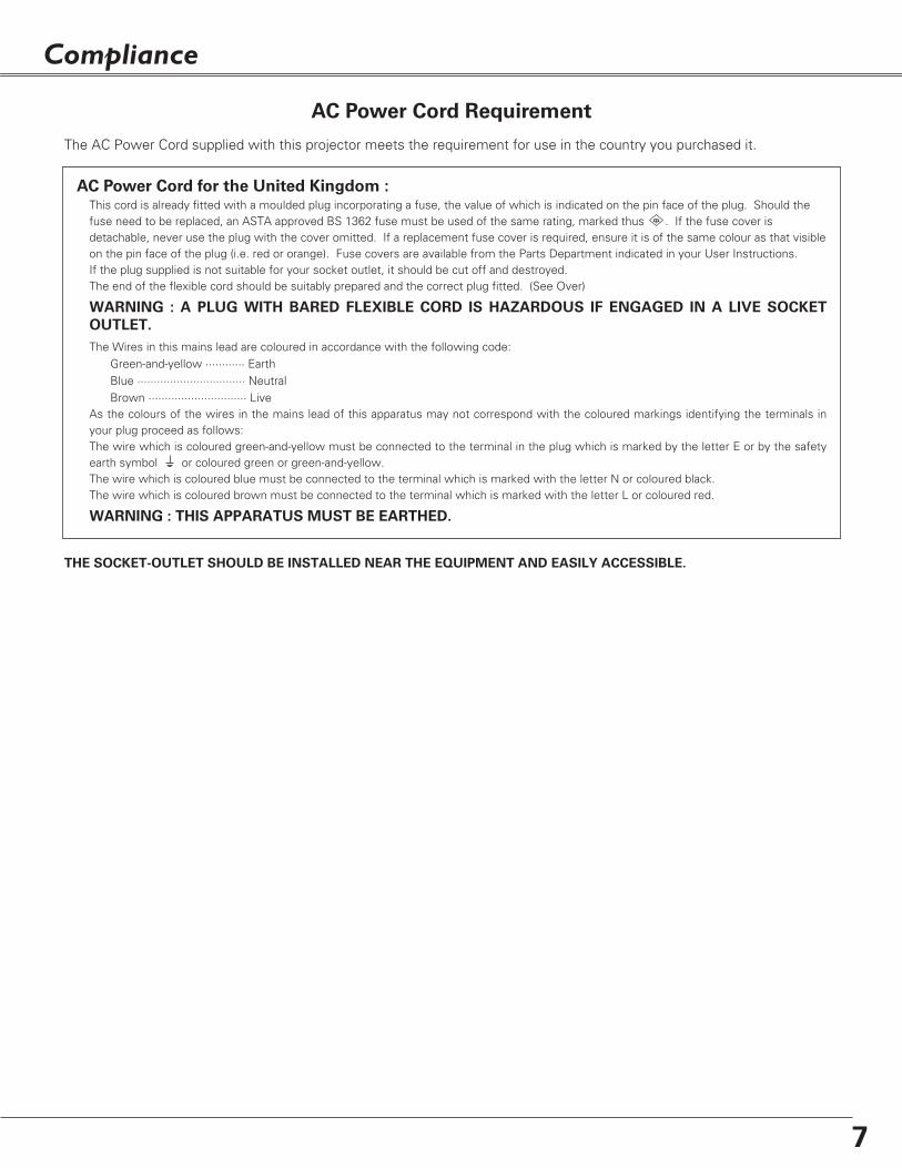
AC Power Cord for the United Kingdom :This cord is already fitted with a moulded plug incorporating a fuse, the value of which is indicated on the pin face of the plug. Should thefuse need to be replaced, an ASTA approved BS 1362 fuse must be used of the same rating, marked thus . If the fuse cover isdetachable, never use the plug with the cover omitted. If a replacement fuse cover is required, ensure it is of the same colour as that visibleon the pin face of the plug (i.e. red or orange). Fuse covers are available from the Parts Department indicated in your User Instructions.If the plug supplied is not suitable for your socket outlet, it should be cut off and destroyed.The end of the flexible cord should be suitably prepared and the correct plug fitted. (See Over)
WARNING : A PLUG WITH BARED FLEXIBLE CORD IS HAZARDOUS IF ENGAGED IN A LIVE SOCKET
OUTLET.
The Wires in this mains lead are coloured in accordance with the following code:Green-and-yellow ············ EarthBlue ································· NeutralBrown ······························ Live
As the colours of the wires in the mains lead of this apparatus may not correspond with the coloured markings identifying the terminals inyour plug proceed as follows:The wire which is coloured green-and-yellow must be connected to the terminal in the plug which is marked by the letter E or by the safetyearth symbol or coloured green or green-and-yellow.The wire which is coloured blue must be connected to the terminal which is marked with the letter N or coloured black.The wire which is coloured brown must be connected to the terminal which is marked with the letter L or coloured red.
WARNING : THIS APPARATUS MUST BE EARTHED.
ASA
The AC Power Cord supplied with this projector meets the requirement for use in the country you purchased it.
THE SOCKET-OUTLET SHOULD BE INSTALLED NEAR THE EQUIPMENT AND EASILY ACCESSIBLE.
AC Power Cord Requirement
Compliance

8
Bottom
Back
q Antitheft alarm setting buttons
w Focus Lever
e Projection Lens
r Lens Cover
(See p. 54 for attaching)
t u
!6
!2 !4
!0 !1 CAUTION
Hot air is exhausted from the exhaustvent. Do not put heat-sensitive objectsnear this side.
e yr t
Front
Part Names and Functions
o
i
!5
CAUTION
Do not turn on the projector with puttingthe lens cover on. The light beam maydamage lens cover and result in firehazard.Attach the lens cover while the projectoris not in use to avoid scratching the lenssurface.
y Infrared Remote Receiver
u Indicators
i Speaker
o Air Intake Vent
!0 Power Cord Connector
!1 Terminals and Connectors
!2 Lamp Cover
!3 Air Intake Vents
!4 Air Filters
!5 Battery Compartment
(For Antitheft alarm function)
!6 Adjustable Feet
wq
t Exhaust Vents
!3
✽
✽ Kensington Security Slot
This slot is for a Kensington lock used todeter theft of the projector. For more information, visithttp://www.kensington.com.
*Kensington is a registered trademark of ACCOBrands Corporation.

9
Part Names and Functions
RESET button
A built-in micro processor which controls this unit mayoccasionally malfunction and need to be reset. Press theRESET button with a pen, then the projector shuts down andrestarts. Do not use the RESET function excessively.
Rear Terminal
S-VIDEO IN
MONITOR OUTCOMPUTER IN 2 /
COMPUTER / COMPONENT
AUDIO IN
R
VIDEO IN L(MONO)
(VARIABLE)
AUDIO OUT
COMPUTER IN 1/ COMPONENT IN
USB SERVICE PORT RESET
q w e r t y
i
u
t S-VIDEO IN
Connect the S-VIDEO output from videoequipment to this jack. (p. 17)
y AUDIO IN
Connect the audio output from video equipmentconnected to t or o to this jack. (When the audiooutput is monaural, connect it to L (MONO) jack.)(p. 17)
i COMPUTER/ COMPONENT AUDIO IN
Connect the audio output (stereo) from a computeror video equipment connected to e or r to this jack. (p 16, 18)
o VIDEO IN
Connect the composite video output from videoequipment to VIDEO jack. (p. 17)
r COMPUTER IN 2 / MONITOR OUT
This terminal is switchable and can be used forinput from a computer or output to the othermonitor. Set the terminal up as either Computer input orMonitor output properly. (Used for Monitor out,this terminal outputs only incoming signal fromCOMPUTER IN 1 / COMPONENT IN terminal.)(pp. 16, 45)
u AUDIO OUT(VARIABLE)
Connect an external audio amplifier to this jack.(pp. 16- 18)This terminal outputs sound from AUDIO INterminal (y or i).
q USB (Series B)
In order to operate the computer with the remotecontrol during a presentation, connect the USBport of the computer to the projector with a USBcable. (p. 16)
w SERVICE PORT
This jack is used to service the projector.
✽
✽
e COMPUTER IN 1 / COMPONENT IN
Connect output signal from a computer, RGB scart21-pin video output, or component video output tothis terminal. (pp. 16, 18)When the cable is of the longer variety, it isadvisable to use this terminal and not COMPUTERIN 2 / MONITOR OUT.
o
Part Nam
es & Functions

10
Part Names and Functions
REPLACEPOWER WARNING LAMP
q w e
e LAMP REPLACE indicator
Turn yellow when the life of the projection lamp draws to anend. (pp. 56, 62)
w WARNING indicator
Emit a red light when the projector detects abnormal condition.This also blinks red when the internal temperature of theprojector exceeds the operating range. (pp. 53, 62)
q POWER indicator
It turns red when the projector is in the stand-by mode. It remains green while the projector is under operation. (pp. 19, 20, 62)
Top Control

11
Part Names and Functions
Part Nam
es & Functions
q
e
w
w Button 1-3
Used for Antitheft alarm setting.e ALARM indicator
Blinks red to indicate the battery condition or key operation.
q F button
Used for Antitheft alarm setting.
Antitheft Alarm Setting Buttons
These buttons are used for Antitheft alarm function. (pp. 50-52)

12
Part Names and Functions
To ensure safe operation, please observe the followingprecautions :– Do not bend, drop the remote control or expose the
remote control to moisture or heat.– For cleaning, use soft dry cloth. Do not apply benzene,
thinner, splay or any chemical material.
t
e
!0
i
!4
r
!5
!3
q POWER ON-OFF button
Turn the projector on or off. (pp. 19, 20)
w VIDEO buttonSelect VIDEO input source. (pp. 24, 35)
e COMPUTER buttonSelect COMPUTER input source. (pp. 24, 26, 36)
r MENU buttonOpen or close the On-Screen Menu. (p. 21)
i PAGE ed buttons
Scroll back and forth pages on the screen when giving a presentation. Connect the projector and your computer with a USB cable to use these buttons. (pp. 9, 16)
!1
u D.ZOOM ed buttonsZoom in and out the image. (pp. 25, 34)
!5 AUTO PC button
Automatically adjust the computer image to its optimum setting. (pp. 25, 28)
!4 IMAGE button
Select the image level. (pp. 25, 31, 38)
o FREEZE button
Freeze the picture. (p. 24)
!2 MUTE buttonMute the sound. (p 24)
!3 P-TIMER buttonOperate the P-timer function. (p. 25)
!0 NO SHOW buttonTemporarily turn off the image on the screen. (p. 25)
!6 KEYSTONE buttonCorrect the keystone distortion. (pp. 23, 42)
t Point ed 7 8 ( VOLUME + / – ) buttons– Select an item or adjust the value in the On-Screen Menu. (p. 21)– Pan the image in Digital zoom + mode. (p. 34)– Adjust the volume level. (Point 7 8 buttons) (p. 24)
y SELECT button– Execute the selected item. (p. 21)– Expand or compress the image in Digital zoom mode. (p. 34)
qw
Remote Control
y
u
o
!6
!2 !1 LAMP CONTROL button
Select the lamp mode. (pp. 25, 46)
You can turn on or operate theprojector ONLY via the remotecontrol.
Make sure not to lose the remotecontrol.

13
Part Names and Functions
1 2 3
To insure safe operation, please observe the following precautions:● Use (2) AA or LR6 type alkaline batteries.● Always replace batteries in sets.● Do not use a new battery with a used battery.● Avoid contact with water or liquid.● Do not expose the remote control to moisture or heat.● Do not drop the remote control.● If the battery has leaked on the remote control, carefully wipe the case clean and install new
batteries.● Risk of explosion if a battery is replaced by an incorrect type. ● Dispose of used batteries according to the instructions.
Open the batterycompartment lid.
Install new batteries intothe compartment.
Replace thecompartment lid.
Two AA size batteries
For correct polarity (+and –), be sure batteryterminals are in contactwith pins in thecompartment.
Point the remote control toward the projector(Infrared Remote Receiver) when pressing anybutton. Maximum operating range for theremote control is about 16.4’ (5m) and 60° infront of the projector.
Operating Range
30°
30°
Remote Control Battery Installation
16.4’(5 m)
Part Nam
es & Functions

14
✔Note:• This projector is not equipped with optical zoom. To adjust the screen size, change the throw distance.• The brightness in the room has a great influence on picture quality.
It is recommended to limit the ambient lighting in order to get the best image.• The values below are approximate and may vary from the actual sizes.
64”
70”
78”
80”
60”
A
B
3.38' (1.03m)
3.28' (1.00m)
2.92' (0.89m)
2.66' (0.81m)
A : B = 10 : 1.2
Screen Size(W x H) mm
4 : 3 aspect ratio
Throw distance
60”
1219 x 914
2.49' (0.76m)
64”
1300 x 975
2.66' (0.81m)
70”
1422 x 1067
2.92' (0.89m)
78”
1585 x 1189
3.28' (1.00m)
80”
1626 x 1219
3.38' (1.03m)
(Inch Diagonal)
2.49' (0.76m)
For projector positioning, see the figures below. The projector should be set horizontally to the flat screen.
(Center)
Projection angle can be adjusted up to 10.0 degrees withthe adjustable feet.
Lift the front of the projector and pull upward the feetlock latches on both sides of the projector.
1
Adjustable Feet
Feet Lock Latches
Release the feet lock latches to lock the adjustablefeet and rotate the adjustable feet to adjust theposition and tilt.
2
To retract the adjustable feet, lift the front of theprojector and pull and undo the feet lock latches.Keystone distortion of the projected image can becorrected by menu operation. (pp. 23, 42)
3
Adjustable Feet
Positioning the Projector
Installation

15
NOTE ON THE POWER CORD
AC power cord must meet requirement of the country where you use the projector.Confirm the AC plug type with the chart below and proper AC power cord must be used.If supplied AC power cord does not match your AC outlet, contact your sales dealer.
To power cord connector on your projector.
Projector side AC outlet side
Ground
To the AC outlet.(120 V AC)
For Continental EuropeFor the U.S.A. and Canada
This projector uses nominal input voltages of 100-120 V or200-240 V AC. This projector automatically selects thecorrect input voltage. It is designed to work with single-phase power systems having a grounded neutral conductor.To reduce the risk of electrical shock, do not plug into anyother type of power system.Consult your authorized dealer or service station if you arenot sure of the type of power being supplied.Connect the projector with all peripheral equipment beforeturning the projector on. (See pp. 16-18 for connection)
CAUTION
For safety, unplug the AC power cord when the projectoris not in use. When this projector is connected to anoutlet with the AC power cord, it is in Stand-by mode andconsumes a little electric power.
Connecting the AC Power Cord
Connect the AC power cord (supplied) to theprojector.The AC outlet must be near this equipment andmust be easily accessible.
For the U.K.
To the AC outlet.(200 - 240 V AC)
To the AC outlet.(200 - 240 V AC)
Installation
Installation

16
Installation
Connecting to a Computer
ONON
S-VIDEO IN
MONITOR OUTCOMPUTER IN 2 /
COMPUTER / COMPONENT
AUDIO IN
R
VIDEO IN L(MONO)
(VARIABLE)
AUDIO OUT
COMPUTER IN 1/ COMPONENT IN
USB SERVICE PORT RESET
Cables used for connection • VGA Cables (Mini D-sub 15 pin) (Only one cable is supplied.) •USB Cable • Audio Cables (Mini Plug: stereo) (Not all the cables are suppled with this projector.)
External Audio Equipment
VGA cable USB cable
Audio cable(stereo) Audio cable
(stereo)
Monitor Outputor
Monitor Input
USB portAudio Output
USB
COMPUTER/COMPONENTAUDIO IN
AUDIO OUT(stereo)
Audio Input
COMPUTER IN 2/MONITOR OUT
Unplug the power cords of both theprojector and external equipment fromthe AC outlet before connecting thecables.
✔Note:• Input sound to the COMPUTER / COMPONENT AUDIO IN
terminal when using the COMPUTER IN 1 / COMPONENT IN andthe COMPUTER IN 2/MONITOR OUT terminal as input.
• When connecting the AUDIO OUT to external audio equipment,the projector's built-in speaker is disconnected.
• When the cable is of the longer variety, it is advisable to use theCOMPUTER IN 1 / COMPONENT IN and not the COMPUTER IN2 / MONITOR OUT.
• See p. 65 for ordering optional parts.
Monitor Output
COMPUTER IN 1/ COMPONENT IN
VGA cable
This terminal is switchable. Set up theterminal as either Computer input orMonitor output. (See p. 45.)

17
S-VIDEO IN
MONITOR OUTCOMPUTER IN 2 /
COMPUTER / COMPONENT
AUDIO IN
R
VIDEO IN L(MONO)
(VARIABLE)
AUDIO OUT
COMPUTER IN 1/ COMPONENT IN
USB SERVICE PORT RESET
Installation
Connecting to Video Equipment
Cables used for connection • Video and Audio Cable (RCA x 3) • S-VIDEO Cable • Audio Cable (Mini Plug: stereo) (Not all the cables are suppled with this projector.)
✔Note:• When connecting AUDIO OUT to external audio equipment, the
projector's built-in speaker is disconnected.• See p. 65 for ordering optional parts.
External Audio Equipment
Audio cable (stereo)
VIDEOS-VIDEO
S-Video cable Video and audio cable
Composite Video and Audio OutputS-Video Output
AUDIO IN
Audio Input
AUDIO OUT(stereo)
(R) (L)
(R) (L) (Video)
(Video)
Unplug the power cords of both the projector andexternal equipment from the AC outlet before connectingthe cables.
Installation

18
Installation
Connecting to Component Video Equipment
S-VIDEO IN
MONITOR OUTCOMPUTER IN 2 /
COMPUTER / COMPONENT
AUDIO IN
R
VIDEO IN L(MONO)
(VARIABLE)
AUDIO OUT
COMPUTER IN 1/ COMPONENT IN
USB SERVICE PORT RESET
Cables used for connection• Audio Cables (Mini Plug :stereo) • Scart-VGA Cable • Component Cable • Component-VGA Cable (Not all the cables are suppled with this projector.)
✔Note:• When connecting AUDIO OUT to external audio equipment, the
projector's built-in speaker is disconnected.• See p. 65 for ordering optional parts.
External Audio Equipment
COMPUTER IN 1/ COMPONENT IN
C O M P U T E R /COMPONENTAUDIO IN
Audio cable (stereo)
Audio cable (stereo)
Audio Input
Component Video Output(Y, Pb/Cb, Pr/Cr)
RGB Scart 21-pin Output
Audio Output
Scart -VGAcable
Component-VGAcable
AUDIO OUT(stereo)
Componentcable
Unplug the power cords of both the projector andexternal equipment from the AC outlet before connectingthe cables.

19
Connect the projector's AC power cord into an ACoutlet. The POWER indicator becomes red.
Press the POWER ON-OFF button on the remotecontrol. The POWER indicator becomes green and thecooling fans start to operate. The preparation displayappears on the screen and the count down starts.
2
3
116
The preparation display disappears after 30seconds.
4 After the countdown, the input source that wasselected last and the Lamp mode status icon (see p.46) appear on the screen.If the projector is locked with a PIN code, PIN codeInput Dialog Box appear. Enter the PIN code asinstructed below. (See p. 46 for Lamp mode)
Selected Input Source and Lamp Mode
Complete peripheral connections (with a computer,VCR, etc.) before turning on the projector.
Lamp mode
Pointer
After the OK icondisappears, you canoperate the projector.
PIN Code Input Dialog Box
Turning On the Projector
Basic Operation
Enter a PIN code
Installation
Select a number by pressing the Point 7 8 buttons and fixthe number with the SELECT button. The number changesto "✳". If you fixed an incorrect number, move the pointerto "Set" or "Clear" once by pressing the Point d button, thenreturn to "PIN code". Enter the correct number again.Repeat this step to complete entering a four-digit number."1234" is set as the initial PIN code at the factory.
When the four-digit number is fixed, the pointer isautomatically move to "Set". Press the SELECT button sothat you can start to operate the projector.
If you entered an incorrect PIN code, "PIN code" and thenumber (✳✳✳✳) turn red and disappear. Enter the correctPIN code all over again.
What is PIN code?
PIN code is a security code using Personal IdentificationNumber that allows the person who knows it to operate theprojector. Setting PIN code prevents others except thespecific users from operating the projector. A PIN code consists of a four-digit number. Refer to PINcode lock function in Setting on pp. 47, 48 for lockingoperation of the projector with your PIN code.
✔Note:• When the Logo select function is "Off", the logo
is not shown on the screen. (p. 43)• When the "Countdown off" or "Off" is selected in
the Display function, the countdown is not shownon the screen. (p. 42)
• During the countdown period, all operations areinvalid.
• If the correct PIN code number is not entered for3 minutes after the PIN code dialog boxappeared, the projector is turned offautomatically.
CAUTION ON HANDLING PIN CODEIf you forget your PIN code, the projector can nolonger be started. Set a new PIN code with specialcare, take a memo and keep it at hand. Should thePIN code be missing or forgotten, consult yourdealer or service center.

20
Basic Operation
Press the POWER ON-OFF button on the remotecontrol, and "Power off?" appears on the screen.
Press the POWER ON-OFF button again to turn off theprojector. The POWER indicator starts to blink red, andthe cooling fans keep operating. (You can select thelevel of fan quietness and rotation speed. See p. 49.)At this time you can disconnect the AC power cordeven if the fans are still running.
1
2
TO MAINTAIN THE LIFE OF THE LAMP, ONCEYOU TURN THE PROJECTOR ON, WAIT ATLEAST 5 MINUTES BEFORE TURNING IT OFF.
3 When the projector has cooled down enough to beturned on again, the POWER indicator becomes red.
The message disappears after 4 seconds.
✔Note:• When the On start function is "On", this projector is turned on
automatically by connecting the AC power cord to an AC outlet. (p. 46)
• Do not operate the projector continuously without rest. Continuoususe may result in shortening the lamp life. Turn off the projectorand give it a rest about an hour in every 24 hours.
• The running speed of cooling fans is changed according to thetemperature inside the projector.
• Do not put the projector in a case before the projector is cooledenough.
• If the WARNING indicator blinks or emits a red light, see "WarningIndicator" on p. 53.
• While the POWER indicator is blinking, lamp is being cooled downand the projector cannot be turned on. Wait until the POWERindicator becomes red to be turned on again.
Turning Off the Projector

21
Basic Operation
Menu bar Pointer
(red framed )
Menu icon
Item data
Press the Point 7 8buttons to adjustthe value.
SELECT
button
Pointer (red framed )
Press the Point edbuttons to move thepointer.
Item
How to Operate the On-Screen Menu
On-Screen Menu
Quit
Exit this menu.
The projector can be adjusted or set via the On-ScreenMenu. Refer to the following pages regarding eachadjustment and setting procedure.
Press the Point 7 8 buttons to select a Menu icon.Press the Point ed buttons to select an item.
Press the SELECT button to show the item data. Toadjust the data, press the Point 7 8 buttons. Refer tothe following pages for each adjustment.
To close the On-Screen Menu, press the MENUbutton again .
Press the MENU button to display the On-ScreenMenu.
✔Note:• The selected item is not active until the SELECT button is pressed.
1
2
3
SELECT button
POINT buttons
Remote ControlMENU button
Basic O
peration
22
Basic Operation
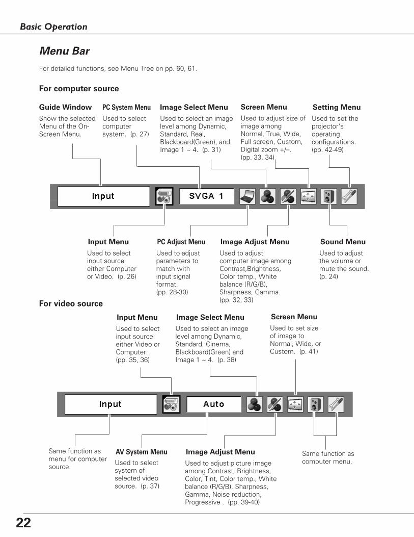
Menu Bar
PC System Menu
Used to selectcomputersystem. (p. 27)
Image Adjust Menu
Used to adjustcomputer image amongContrast,Brightness,Color temp., Whitebalance (R/G/B),Sharpness, Gamma. (pp. 32, 33)
Setting Menu
Used to set theprojector'soperatingconfigurations.(pp. 42-49)
Sound Menu
Used to adjustthe volume ormute the sound.(p. 24)
Image Select Menu
Used to select an imagelevel among Dynamic,Standard, Real,Blackboard(Green), andImage 1 ~ 4. (p. 31)
For computer source
AV System Menu
Used to selectsystem ofselected videosource. (p. 37)
Image Adjust Menu
Used to adjust picture imageamong Contrast, Brightness,Color, Tint, Color temp., Whitebalance (R/G/B), Sharpness,Gamma, Noise reduction,Progressive . (pp. 39-40)
For video source
Same function ascomputer menu.
Input Menu
Used to selectinput sourceeither Video orComputer.(pp. 35, 36)
PC Adjust Menu
Used to adjustparameters tomatch withinput signalformat. (pp. 28-30)
Image Select Menu
Used to select an imagelevel among Dynamic,Standard, Cinema,Blackboard(Green) andImage 1 ~ 4. (p. 38)
Screen Menu
Used to set sizeof image toNormal, Wide, orCustom. (p. 41)
Guide Window
Show the selectedMenu of the On-Screen Menu.
Same function asmenu for computersource.
Input Menu
Used to selectinput sourceeither Computeror Video. (p. 26)
Screen Menu
Used to adjust size ofimage amongNormal, True, Wide,Full screen, Custom,Digital zoom +/–.(pp. 33, 34)
For detailed functions, see Menu Tree on pp. 60, 61.

23
Basic Operation
Adjust lens focus with the Focus lever.
Focus Lever
• The arrows are white when there is no correction.• The direction of the arrow which are being corrected
turns red.• The arrows disappear at the maximum correction.• If you press the KEYSTONE button on the remote
control once more while the keystone dialog box isbeing displayed, the keystone adjustment is canceled.
• The adjustable range can be limited depending on theinput signal.
• The projected picture may fluctuate momentlydepending on the keystone adjustment.
If a projected picture has keystone distortion, correct theimage with Keystone adjustment.Press the KEYSTONE button on the remote control. Thekeystone dialog box appears. Correct keystone distortion by pressing the Point ed
buttons. Keystone adjustment can be memorized. (p. 42)
Reduce the upper width with the Point e button.
Reduce the lower width with the Point d button.
Keystone Correction
Remote Control
KEYSTONE button
POINT ed buttons
Focus Adjustment
Basic O
peration
24
Basic Operation
Remote Control
Remote Control Operation
Use the remote control for some frequently used operations.Just pressing one of the buttons enables you to make the operation easily and you do not have to call up theOn-Screen Menu.
COMPUTER /VIDEO
button
✔Note:• See the next page for the other buttons.
Press the FREEZE button to freeze the picture on thescreen. To cancel the Freeze function, press the FREEZEbutton again or press any other button.
FREEZE button
Press the COMPUTER or VIDEO button to select the inputsource.For more detail, see pp. 26, 35, 36.
COMPUTER / VIDEO button
FREEZE button
1
2
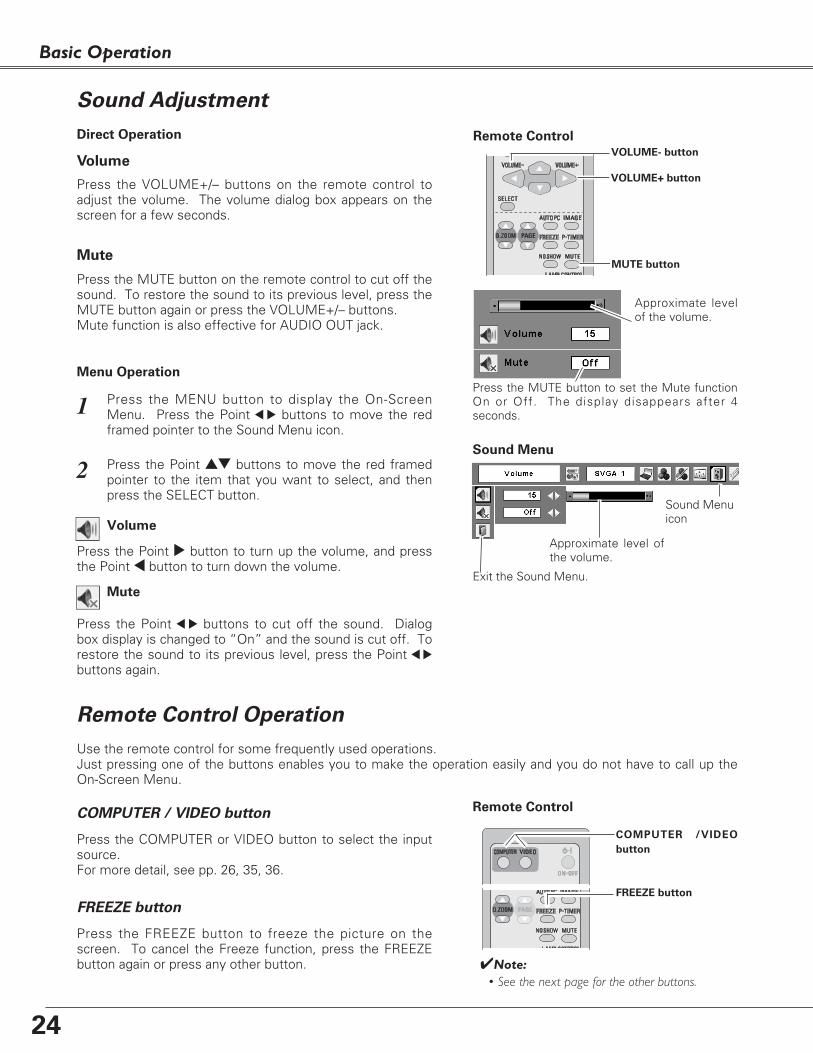
Press the MENU button to display the On-ScreenMenu. Press the Point 7 8 buttons to move the redframed pointer to the Sound Menu icon.
Press the VOLUME+/– buttons on the remote control toadjust the volume. The volume dialog box appears on thescreen for a few seconds.
Press the MUTE button on the remote control to cut off thesound. To restore the sound to its previous level, press theMUTE button again or press the VOLUME+/– buttons.Mute function is also effective for AUDIO OUT jack.
Press the Point 7 8 buttons to cut off the sound. Dialogbox display is changed to “On” and the sound is cut off. Torestore the sound to its previous level, press the Point 7 8
buttons again.
Press the Point ed buttons to move the red framedpointer to the item that you want to select, and thenpress the SELECT button.
Approximate level ofthe volume.
Exit the Sound Menu.
Approximate levelof the volume.
Press the MUTE button to set the Mute functionOn or Off. The display disappears after 4seconds.
Sound Menu
Sound Menu icon
Volume
Remote Control
VOLUME+ button
VOLUME- button
MUTE button
Volume
Mute
Press the Point 8 button to turn up the volume, and pressthe Point 7 button to turn down the volume.
Mute
Direct Operation
Menu Operation
Sound Adjustment

25
Basic Operation
Remote Control
D.ZOOM
buttons
NO SHOW
button
AUTO PC
button
✔Note:• See the previous page for the other buttons.
KEYSTONE button
(See p. 23)
POINT ed
buttons
black out ➜ the captured image ➜ normal ➜ • • • • •
Press the NO SHOW button to black out the image. Torestore to normal, press the NO SHOW button again orpress any other button. When a projected image iscaptured and set as “User” in the Logo selection (p. 43),the screen changes each time you press the NO SHOWbutton as follows.
The message disappears after 4 seconds.
NO SHOW button
Press the AUTO PC button to operate the Auto PC function.For more detail, see p. 28.
AUTO PC button
Press the D.ZOOM buttons to zoom in and zoom out theimages.For more detail, see p. 34.
D.ZOOM buttons
Press the P-TIMER button. The timer display “00 : 00”appears on the screen and the timer starts to count time(00 : 00 ~ 59 : 59). To stop the P-Timer, press the P-TIMER button. Press theP-TIMER button again, then the P-timer display disappears.
P-TIMER button
LAMP CONTROL button
P-Timer display
Press the IMAGE button to select an image level of thescreen.For more detail, see pp. 31, 38.
IMAGE button
LAMP CONTROL
button
P-TIMER button
IMAGE button
VOLUME
+/- buttons
(See p. 24)
Press the LAMP CONTROL button to select the lamp modefor changing the brightness of the screen.
Normal ....Normal brightness Auto ........Brightness according with the input signal Eco ..........Lower brightness reduces the lamp power
consumption and extends thelamp life.
For detail, see p. 23.
KEYSTONE button
Basic O
peration

26
Select either Computer 1 or Computer 2 by pressing theCOMPUTER button on the remote control.Before using COMPUTER button, select the correct inputsource through Menu operation as described below.
Press the MENU button to display the On-ScreenMenu. Press the Point 7 8 buttons to move the redframed pointer to the Input Menu icon.
1
Computer1
Input Menu
Press the Point ed buttons to move the red arrowpointer to either Computer 1 or Computer 2, and thenpress the SELECT button.
2
After the Source Select Menu appeared for Computer1, move the pointer to RGB and then press theSELECT button.
3
Input Menu
COMPUTER button
Computer 1
Computer 2
Input Source Selection
Direct Operation
Menu Operation
Computer Input
Move the pointer (redarrow) to Computer 1and press the SELECTbutton.
Input Menu icon
Move the pointer (red arrow)to Computer 2 and press theSELECT button.
Move the pointer to RGBand press the SELECTbutton.
Source Select Menu
Remote Control
COMPUTER button
✔Note:• Computer 2 is not displayed when the COMPUTER IN
2/MONITOR OUT terminal is set as Monitor out. (p. 45) • Computer 2 (COMPUTER IN 2 / MONITOR OUT) can accept only
RGB signal.

27
Computer Input
The Auto PC Adjustmentfunction operates to adjust the projector.
PC System Menu
The PC System Menu icon Selected system is displayed.
Systems on this dialog box can be selected.
Press the MENU button to display the On-ScreenMenu. Press the Point 7 8 buttons to move the redframed pointer to the PC System Menu icon.
Press the Point ed buttons to move the red arrowpointer to the system that you want to set, and thenpress the SELECT button.
1
2
PC System Menu
Custom Mode (1~5) set in thePC Adjust Menu. (pp. 28, 30)
PC system can also be selected manually.
Computer System Selection
This projector automatically tunes to various types of computers based on VGA, SVGA, XGA, SXGA, WXGA, orUXGA with its Multi-scan system and Auto PC Adjustment. If Computer is selected as a signal source, thisprojector automatically detects the signal format and tunes to project a proper image without any additionalsetting. (Signal formats provided in this projector is shown on p. 63 )
One of the following messages may appear when:
The projector cannot recognize the connectedsignal conforming to the provided PC Systems."Auto" is displayed on the PC System Menu iconand the Auto PC Adjustment function works todisplay proper images. If the image is notprojected properly, adjust manually. (pp. 29, 30)
There is no signal input from computer. Checkthe connection between your computer and theprojector. (See " Troubleshooting" p. 58)
Auto
-----
The preset system is manually adjusted in thePC Adjust Menu. The adjusted data can bestored in Mode 1~5. (pp. 29, 30)
Mode 1
PC Systems provided in this projector isselected. The projector selects a proper systemprovided in the projector and displays it.
SVGA 1
Selecting Computer System Manually
*Mode 1 and SVGA 1 are examples.
Com
puter Inp
ut

28
Computer Input
Auto PC Adjustment function is provided to automatically adjust Fine sync, Total dots, Horizontal, and Vertical toconform to your computer. Auto PC Adjustment function can be operated as follows.
Move the red framedpointer to the Auto PC Adj.item and press the SELECTbutton.
"Please wait..." appearswhile Auto PC adjustmentis in process.
PC Adjust Menu
PC Adjust Menu icon
To store adjustment parameters
Adjustment parameters from Auto PC Adjustment can bememorized in this projector. Once parameters arememorized, the setting can be done just by selecting Modein the PC System Menu (p. 27). See “Store” on p. 30.
✔Note:• Fine sync, Total dots, Horizontal, and Vertical of some computers
cannot be fully adjusted with this Auto PC Adjustment function.When the image is not provided properly with this operation,manual adjustments are required. (pp. 29, 30)
• The Auto PC Adjustment cannot be operated when 480i, 575i,480p, 575p, 720p,1035i, or 1080i is selected in the PC SystemMenu(p. 27)
Auto PC Adjustment
Press the MENU button to display the On-ScreenMenu. Press the Point 7 8 buttons to move the redframed pointer to "PC Adjust Menu".
1
2 Press the Point ed buttons to move the red framedpointer to "Auto PC Adj." and then press the SELECTbutton twice.
Auto PC Adj.
Menu Operation
The Auto PC adjustment function can be operated directly bypressing the AUTO PC button on the remote control.
Remote Control
AUTO PC button
Direct Operation

29
Computer Input
Press the MENU button to display the On-ScreenMenu. Press the Point 7 8 buttons to move the redframed pointer to the PC Adjust Menu icon.
1
2 Press the Point ed buttons to move the red framedpointer to the item that you want to adjust and thenpress the SELECT button to display the adjustmentdialog box. Press the Point 7 8 buttons to adjust thevalue.
Move the red framedpointer to an item andpress the SELECT button.
PC Adjust MenuPC Adjust Menu icon
Cut out flicker from the image displayed. Press the Point 7
8 buttons to adjust the value. (From 0 to 31)
Fine sync
Adjust the number of total dots in one horizontal period.Press the Point 7 8 buttons to adjust number to match yourPC image.
Total dots
Press the Point 7 8 buttons to adjust the horizontal pictureposition.
Horizontal
Press the Point 7 8 buttons to adjust the vertical pictureposition.
Vertical
Press the SELECT button to show H-sync freq. and V-syncfreq. of the connected computer.
Current mode
Adjust clamp level. When the image has dark bars, try thisadjustment.
Clamp
Press the SELECT buttonat this item to adjust otheritems.
Press the Point 7 8buttonsto adjust the value.
Status (Stored / Free) of theselected Mode.
Selected Mode
Press the SELECT button at"Current mode" to show theinformation of the connectedcomputer.
Manual PC Adjustment
Some computers employ special signal formats which may not be tuned by Multi-scan system of this projector.Manual PC Adjustment enables you to precisely adjust several parameters to match those signal formats. Theprojector has 5 independent memory areas to memorize those parameters which are manually adjusted. Youcan recall the setting for a specific computer.
Com
puter Inp
ut

30
Computer Input
Adjust the horizontal area displayed by this projector. Pressthe Point 7 8 buttons to decrease/increase the value.
Display area H
Adjust the vertical area displayed by this projector. Pressthe Point 7 8 buttons to decrease/increase the value.
Display area V
Reset
Store
Exit the PC Adjust Menu.
Quit
To store adjusted data, move the red framed pointer to the"Store" and then press the SELECT button. Move the redarrow pointer to any of Mode 1 to 5 in which you want tostore and then press the SELECT button.
To reset the adjusted data, select Reset and press theSELECT button. The confirmation box appears and thenselect "Yes". All adjustments return to their previousfigures.
Mode free
Vacant Mode Values of “Total dots,”“Horizontal,” “Vertical,” “Display area H,” and“Display area V.”
Close this dialog box.
To store adjusted data
To clear adjusted dataTo clear the stored data, move the red framed pointer to the"Mode free" and then press the SELECT button. Move thered arrow pointer to the Mode that you want to clear andthen press the SELECT button.
✔Note:• Display area (H/V) cannot be selected when 480i, 575i, 480p,
575p, 720p, 1035i, or 1080i is selected in the PC System Menu (p. 27).
This Mode hasstored parameters .
Move the red framedpointer to an item andpress the SELECT button.

31
Computer Input
Press the MENU button to display the On-ScreenMenu. Press the Point 7 8 buttons to move the redframed pointer to the Image Select Menu icon.
1
2 Press the Point ed buttons to move the red framedpointer to the level that you want to set and then pressthe SELECT button.
Move the red framed pointerto the level and press theSELECT button.
The level being selected.
Image Select Menu
Normal picture level preset on this projector.
Standard
Picture level with improved halftone for graphics.
Real
Picture level suitable for the image projected on ablackboard. See above for further description.
Blackboard(Green)
Image Select Menu icon
Select an image level among Dynamic, Standard, Real,Blackboard(Green), Image 1, Image 2, Image 3, and Image 4by pressing the IMAGE button on the remote control.
IMAGE button
Dynamic
Real
Image 1
Image 2
Image 3
Normal picture level preset on this projector.
Picture level with improved halftone for graphics.
Standard
Real
Image 1~4
Image Level Selection
Direct Operation
Menu Operation
Image 4
User preset image in the Image Adjust Menu (p. 33).
Image 1~4
Blackboard(Green)
Picture level suitable for the image projected on ablackboard.This mode enhances the image projected on a blackboard.This mode is mainly effective on a green colored board, nottruly effective on a black colored board.
Blackboard(Green)
Picture level suitable for viewing picture in a bright room.
Dynamic
Picture level suitable for viewing picture in a bright room.Dynamic
User preset image in the Image Adjust Menu (p. 33).
Standard
Remote Control
IMAGE
button
Com
puter Inp
ut

32
Computer Input
Press the Point 7 8 buttons to adjust the value.
Press the MENU button to display the On-ScreenMenu. Press the Point 7 8 buttons to move the redframed pointer to the Image Adjust Menu icon.
1
2 Press the Point ed buttons to move the red framedpointer to the item that you want to adjust, and thenpress the SELECT button. The level of each item isdisplayed. Adjust each level by pressing the Point 7 8
buttons.
Move the red framedpointer to the item to beselected and then pressthe SELECT button.
Image Adjust Menu
Press the Point 7 button to decrease the contrast and thePoint 8 button to increase contrast. (From 0 to 63.)
Press the Point 7 button to adjust the image darker and thePoint 8 button to adjust the image brighter. (From 0 to 63.)
Contrast
Brightness
Image Adjust Menu icon
Press the Point 7 button to lighten the red tone and thePoint 8 button to deepen the red tone. (From 0 to 63.)
White balance (Red)
Press the Point 7 button to lighten the green tone and thePoint 8 button to deepen the green tone. (From 0 to 63.)
White balance (Green)
Press the Point 7 button to lighten the blue tone and thePoint 8 button to deepen the blue tone. (From 0 to 63.)
White balance (Blue)
Selected Image level
Press the Point 7 button or the Point 8 button for Colortemp. level that you want to select. (XLow, Low, Mid, orHigh)
Color temp.
Image Level Adjustment
✔Note:• After adjusting any of the White balance Red,
Green or Blue, the Color temp changes to "Adj.".
Press the Point 7 8 buttons to get better balance ofcontrast. (From 0 to 15.)
Gamma
Press the Point 7 button to soften the image and the Point8 button to sharpen the image. (From 0 to 15.)
Sharpness
To reset the adjusted data, select Reset and press theSELECT button. The confirmation box appears and thenselect "Yes". All adjustments return to their previousfigures.
Reset
33
Computer Input
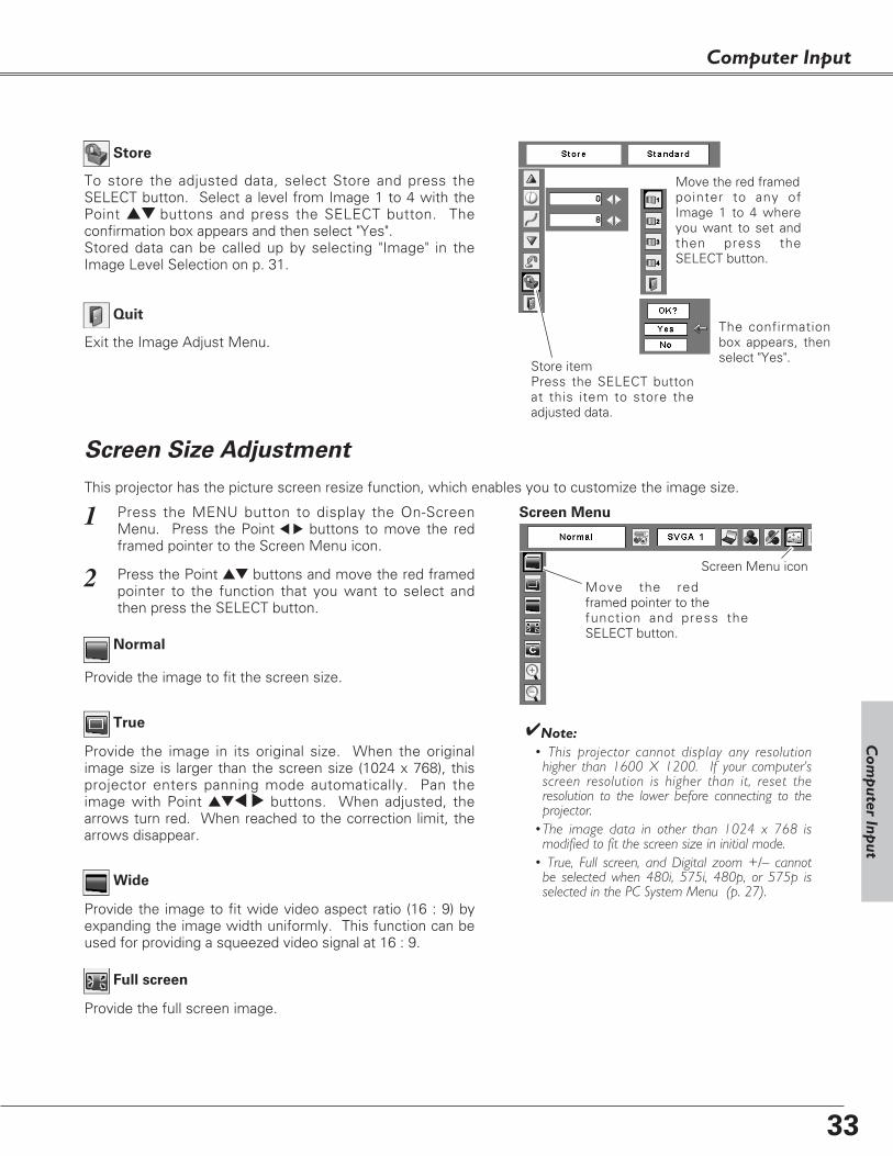
Store
Exit the Image Adjust Menu.
Quit
To store the adjusted data, select Store and press theSELECT button. Select a level from Image 1 to 4 with thePoint ed buttons and press the SELECT button. Theconfirmation box appears and then select "Yes". Stored data can be called up by selecting "Image" in theImage Level Selection on p. 31.
Move the red framed pointer to any ofImage 1 to 4 whereyou want to set andthen press theSELECT button.
The confirmationbox appears, thenselect "Yes".
Store itemPress the SELECT buttonat this item to store theadjusted data.
This projector has the picture screen resize function, which enables you to customize the image size.
Press the MENU button to display the On-ScreenMenu. Press the Point 7 8 buttons to move the redframed pointer to the Screen Menu icon.
1
Move the redframed pointer to the function and press theSELECT button.
Press the Point ed buttons and move the red framedpointer to the function that you want to select andthen press the SELECT button.
2
Screen Menu
Screen Menu icon
Screen Size Adjustment
Wide
Provide the image to fit the screen size.
Normal
True
Provide the image in its original size. When the originalimage size is larger than the screen size (1024 x 768), thisprojector enters panning mode automatically. Pan theimage with Point ed7 8 buttons. When adjusted, thearrows turn red. When reached to the correction limit, thearrows disappear.
Provide the image to fit wide video aspect ratio (16 : 9) byexpanding the image width uniformly. This function can beused for providing a squeezed video signal at 16 : 9.
Full screen
Provide the full screen image.
✔Note:• This projector cannot display any resolution
higher than 1600 X 1200. If your computer’sscreen resolution is higher than it, reset theresolution to the lower before connecting to theprojector.
•The image data in other than 1024 x 768 ismodified to fit the screen size in initial mode.
• True, Full screen, and Digital zoom +/– cannotbe selected when 480i, 575i, 480p, or 575p isselected in the PC System Menu (p. 27).
Com
puter Inp
ut

34
Computer Input
When the Digital zoom + is selected, the On-Screen Menudisappears and “D. zoom +” is displayed. Press theSELECT button to expand the image size. And press thePoint ed7 8 buttons to pan the image. The Panningfunction can work only when the image is larger than thescreen size.A projected image can be also expanded by pressing theD.ZOOM ▲ button on the remote control.
To exit the Digital zoom +/– mode, press any button exceptthe D.ZOOM ▲▼ buttons, SELECT, and Point button.
Digital zoom +
When Digital zoom – is selected, the On-Screen Menudisappears and “D. zoom –”is displayed. Press the SELECTbutton to compress image size. A projected image can be also compressed by pressing theD.ZOOM ▼ button on the remote control.
Digital zoom –
To return to the previous screen size, select a screen size inthe Screen Size Adjustment or select an input source fromthe Input Source Selection (p. 26) again, or adjust the screensize with the D.ZOOM ▲▼ buttons.
Remote Control
D.ZOOM + button
POINT buttons
SELECT button
D.ZOOM - button
For zooming in and out the images
✔Note:• The panning function may not operate properly
if the stored Mode in the PC Adjust Menu isused. (p. 30)
• The minimum compression ratio can be limiteddepending on the input signal or when theKeystone function is working.
• True, Full screen, and Digital zoom +/– cannotbe selected when 480i, 575i, 480p, or 575p isselected in the PC System Menu (p. 27)
• Digital zoom +/- cannot be selected when Fullscreen or True is selected.
Adjust the screen scale and position manually.Press the SELECT button at Custom icon. "Custom" isdisplayed on the screen for a few seconds and then"Aspect" box appears.
Scale H / V .......Adjust the Horizontal / Vertical screenscale.
H&V..................When selecting "On", the aspect ratio isfixed. "Scale V" becomes gray andunselectable. Adjust "Scale H", then thescreen scale is automatically modifiedbased on the aspect ratio.
Position H / V ...Adjust the Horizontal / Vertical screenposition.
Common ........Save the adjusted scale. Press theSELECT button at "Common" to displaythe confirmation box. To save the scale,press the SELECT button at "Yes".When "Custom" is selected, the savedscale is used.
Reset ............Reset "Common" data. Press theSELECT button at "Reset" to display theconfirmation box. To reset, press theSELECT button at "Yes".
Custom
✔Note:•When no signal is detected, Normal is set
automatically and "Aspect" screen disappears.•The adjustable range of Scale H/V and Position
H/V can be limited depending on the inputsignal.
Press the SELECT button at"Common" or "Reset", todisplay confirmation box.

35
Select Video by pressing the VIDEO button on the remotecontrol.Before using VIDEO button, select the correct input sourcethrough menu operation as described below.
Press the MENU button to display the On-ScreenMenu. Press the Point 7 8 buttons to move the redframed pointer to the Input Menu icon.
Press the Point ed buttons to move the red arrowpointer to Video and then press the SELECT button todisplay the Source Select Menu .
1
2
Move the pointer toVideo and press theSELECT button.
VIDEO
Move the pointer to thesource that you want toselect and press theSELECT button.
Source Select Menu (VIDEO)
Input Menu
Move the pointer to the source that you want to selectand then press the SELECT button.
3
When selecting Auto, the projectorautomatically detects incoming video signal, andadjusts itself to optimize its performance. Theprojector selects connection in the followingorder:
1. S-Video2. Video
Auto
When video input signal is connected to theVIDEO jack, select Video.
Video
When video input signal is connected to the S-VIDEO jack, select S-Video.
S-Video
Input Source Selection (Video, S-Video)
Direct Operation
Menu OperationInput Menu icon
Video Input
Remote Control
VIDEO button
Com
puter Inp
ut

36
Video Input
Select Computer 1 by pressing the COMPUTER button onthe remote control.Before using COMPUTER button, select the correct inputsource through Menu operation as described below.
Press the MENU button to display the On-ScreenMenu. Press the Point 7 8 buttons to move the redframed pointer to the Input Menu icon.
1
Computer1
Input Menu
Press the Point ed buttons to move the red arrowpointer to Computer 1 and then press the SELECTbutton.
2
After the Source Select Menu appeared for Computer1, move the pointer to Component or RGB(Scart) andthen press the SELECT button.
3
COMPUTER button
Computer 1
Computer 2
Input Source Selection (Component, RGB Scart 21-pin)
Direct Operation
Menu Operation
Move the pointer (redarrow) to Computer 1and press the SELECTbutton.
Input Menu icon
Move the pointer toComponent or RGB(Scart) and press the SELECTbutton.
Source Select Menu
Remote Control
COMPUTER button
When the input source is coming fromvideo equipment connected to theCOMPUTER IN 1 / COMPONENT INterminal with a Component-VGA Cable,select Component.
Component
When the input source is coming fromvideo equipment connected to theCOMPUTER IN 1 / COMPONENT INterminal with a Scart-VGA Cable, selectRGB (Scart).
RGB (Scart)
✔Note:• Computer 2 is not displayed when the COMPUTER IN
2/MONITOR OUT terminal is set as Monitor out. (p. 45) • Computer 2 (COMPUTER IN 2 / MONITOR OUT) can accept only
RGB signal.

37
Video Input
Press the MENU button to display the On-ScreenMenu. Press the Point 7 8 buttons to move the redframed pointer to the AV System Menu icon.
1
Video System Selection
AV System Menu (Video or S-Video)
AV System Menu (Component)
Press the Point ed buttons to move the red arrowpointer to the system that you want to select and thenpress the SELECT button.
2
If the projector cannot reproduce proper video image, it isnecessary to select a specific broadcast signal formatamong PAL, SECAM, NTSC, NTSC 4.43, PAL-M, and PAL-N.
Move the pointer to asystem and press theSELECT button.
PAL / SECAM / NTSC / NTSC4.43 / PAL-M / PAL-N
The projector automatically detects incoming video signal,and adjusts itself to optimize its performance.
If the projector cannot reproduce a proper video image, it isnecessary to select a specific component video signalformat among 480i, 575i, 480p, 575p, 720p, 1035i, and1080i.
Auto
COMPONENT VIDEO SIGNAL FORMAT
Video or S-Video
Component
The projector automatically detects incoming video system,and adjusts itself to optimize its performance.When Video System is PAL-M or PAL-N, select systemmanually.
AutoAV System Menu icon
Selected system is displayed.
Move the pointer to asystem and press theSELECT button.
AV System Menu icon Selected system is displayed.
✔Note:• The AV System Menu cannot be selected when selecting
RGB(Scart).
Video Input

38
Video Input
Press the MENU button to display the On-ScreenMenu. Press the Point 7 8 buttons to move the redframed pointer to the Image Select Menu icon.
1
2 Press the Point ed buttons to move the red framedpointer to the level that you want to set and then pressthe SELECT button.
Move the red framed pointer to alevel and press the SELECTbutton.
The level being selected.
Image Select Menu
Normal picture level preset on this projector.
Standard
Picture level adjusted for the picture with fine tone.
Cinema
Blackboard(Green)
User preset image in the Image Adjust Menu (pp. 39, 40).
Image1~4
Image Select Menu icon
Select an image level among Dynamic, Standard, Cinema,Blackboard (Green), Image 1, Image 2, Image 3, and Image4 by pressing the IMAGE button on the remote control.
Normal picture level preset on this projector. Standard
Picture level adjusted for the picture with fine tone.Cinema
Blackboard(Green)
User preset image in the Image Adjust Menu (pp. 39, 40).Image 1~4
IMAGE button
Dynamic
Cinema
Image 1
Image 2
Image 3
Image 4
Image Level Selection
Direct Operation
Menu Operation
Picture level suitable for the image projected on ablackboard.This mode enhances the image projected on a blackboard.This mode is mainly effective on a green colored board, nottruly effective on a black colored board.
Picture level suitable for the image projected on aBlackboard. See above for further description.
Blackboard(Green)
Picture level suitable for viewing picture in a bright room.
Dynamic
Picture level suitable for viewing picture in a bright room.Dynamic
Standard
Remote Control
IMAGE
button
39
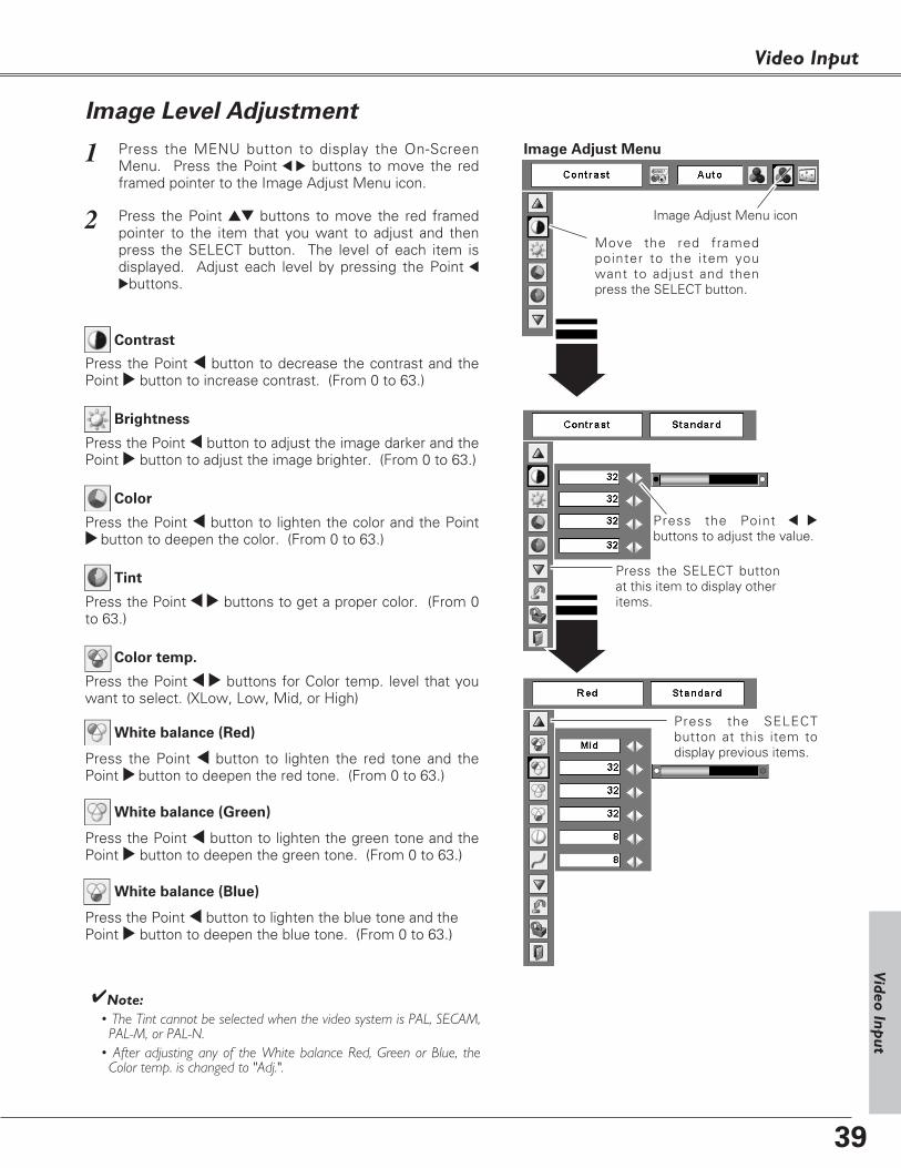
Video Input
Press the Point 7 8
buttons to adjust the value.
Press the MENU button to display the On-ScreenMenu. Press the Point 7 8 buttons to move the redframed pointer to the Image Adjust Menu icon.
1
2 Press the Point ed buttons to move the red framedpointer to the item that you want to adjust and thenpress the SELECT button. The level of each item isdisplayed. Adjust each level by pressing the Point 7
8buttons.
Move the red framedpointer to the item youwant to adjust and thenpress the SELECT button.
Image Adjust Menu
Press the Point 7 button to decrease the contrast and thePoint 8 button to increase contrast. (From 0 to 63.)
Press the Point 7 button to adjust the image darker and thePoint 8 button to adjust the image brighter. (From 0 to 63.)
Contrast
Brightness
Press the SELECT buttonat this item to display other items.
Image Adjust Menu icon
Press the Point 7 button to lighten the color and the Point8 button to deepen the color. (From 0 to 63.)
Press the Point 7 8 buttons to get a proper color. (From 0to 63.)
Color
Tint
Press the Point 7 button to lighten the red tone and thePoint 8 button to deepen the red tone. (From 0 to 63.)
White balance (Red)
Press the Point 7 button to lighten the green tone and thePoint 8 button to deepen the green tone. (From 0 to 63.)
White balance (Green)
Press the Point 7 button to lighten the blue tone and thePoint 8 button to deepen the blue tone. (From 0 to 63.)
White balance (Blue)
Press the SELECTbutton at this item todisplay previous items.
✔Note:• The Tint cannot be selected when the video system is PAL, SECAM,
PAL-M, or PAL-N.• After adjusting any of the White balance Red, Green or Blue, the
Color temp. is changed to "Adj.".
Image Level Adjustment
Press the Point 7 8 buttons for Color temp. level that youwant to select. (XLow, Low, Mid, or High)
Color temp.
Video Input

40
Video Input
To store the adjusted data, select "Store" and press theSELECT button. Select a level from Image 1 to 4 with thePoint ed buttons and press the SELECT button. Theconfirmation box appears and then select "Yes". Stored data can be called up by selecting "Image" in theImage Level Selection on p. 38.
Image Level MenuMove the red framed pointerto an image item to be set andthen press the SELECT button.
To reset the adjusted data, select "Reset" and press theSELECT button. The confirmation box appears and thenselect "Yes". All adjustments return to their previousfigures.
Reset
Store
Exit the Image Adjust Menu.
Quit
✔Note:• Noise reduction and Progressive cannot be selected when 480p,
575p, 720p, 1035i, or 1080i is selected. (p. 37)
Store item
Interlaced video signal can be displayed in a progressivepicture. Select one of the following.
Off...........Disabled.L1............Select “L1” for an active picture.L2............Select “L2” for a still picture.Film........Select “Film” for watching a film. With this
function, the projector reproduces picturesfaithful to the original film quality.
Progressive
Noise reduction
Noise interference on the screen can be reduced. Selectone of the following to get smoother images.
Off...........disabled.L1............lower reduction L2............higher reduction
The confirmation boxappears and thenselect "Yes".
Press the Point 7 8 buttons to get better balance ofcontrast. (From 0 to 15.)
Gamma
Press the Point 7 button to soften the image and the Point8 button to sharpen the image. (From 0 to 15.)
Sharpness

41
Video Input
This projector has the picture screen resize function, which enables you to customize the image size.
Press the MENU button to display the On-ScreenMenu. Press the Point 7 8 buttons to move the redframed pointer to the Screen Menu icon.
Press the Point ed buttons and move the red framedpointer to the function that you want to select andthen press the SELECT button.
1
2Move the red framed pointer to afunction and press the SELECTbutton.
Screen Menu
Screen Menu icon
Provide the image at a wide screen ratio of 16 : 9.
Wide
Provide the image at a normal video aspect ratio of 4 : 3.
Normal
Screen Size Adjustment
Video Input
Adjust the screen scale and position manually.Press the SELECT button at Custom icon. "Custom" isdisplayed on the screen for a few seconds and then"Aspect" box appears.
Scale H / V .......Adjust the Horizontal / Vertical screenscale.
H&V..................When selecting "On", the aspect ratio isfixed. "Scale V" becomes gray andunselectable. Adjust "Scale H", then thescreen scale is automatically modifiedbased on the aspect ratio.
Position H / V ...Adjust the Horizontal / Vertical screenposition.
Common ........Save the adjusted scale. Press theSELECT button at "Common" to displaythe confirmation box. To save the scale,press the SELECT button at "Yes".When "Custom" is selected, the savedscale is used.
Reset ............Reset "Common" data. Press theSELECT button at "Reset" to display theconfirmation box. To reset, press theSELECT button at "Yes".
Custom
✔Note:• Wide is not available when 720p, 1035i, or 1080i is selected in
the AV System Menu (p. 37).• When no signal is detected, Normal is set automatically and
"Aspect" screen disappears.• The adjustable range of Scale H/V and Position H/V can be limited
depending on the input signal.
Press the SELECT button at"Common" or "Reset", todisplay the confirmation box.

42
Display
Blue back
Press the Point 7 8 buttons to switch on/off. When thisfunction is “On,” a blue image is displayed while the inputsignal is not detected.
Keystone
Press the MENU button to display the On-ScreenMenu. Press the Point 7 8 buttons to move the redframed pointer to the Setting Menu icon.
1
2
Language
The language used in the On-Screen Menu is available inEnglish, German, French, Italian, Spanish, Portuguese,Dutch, Swedish, Finnish, Polish, Hungarian, Romanian,Russian, Chinese, Korean, or Japanese.
Set the red framedpointer to the itemand press theSELECT button.Press the Point ed buttons to move the red framed
pointer to the item that you want to set and then pressthe SELECT button. The Setting dialog box appears.
SELECT
button
Press the SELECT button atLanguage item, theLanguage Menu appears.
Setting Menu (Language)
Setting Menuicon
This function corrects distortion of a projected image.Select either Store or Reset with the Point 7 8 buttons, andthen press the SELECT button. The keystone dialog boxappears. Correct keystone with the Point ed buttons. (p. 23)
Store .........Store the keystone correction even when theAC power cord is unplugged.
Reset........Reset the keystone correction when the ACpower cord is unplugged.
Setting
Setting
This projector has Setting menu that allows you to set upthe other various functions described as follows;
Press the SELECTbutton at this item todisplay the otherlanguages.
Press the Point 7 8 buttons to switch on/off. This functiondecides to display On-Screen Displays.On .........................Display all the On-Screen Displays. Use
this function when you want to projectimages after the lamp becomes brightenough. This mode is set as a default..
Countdown off......Display the input image instead of thecountdown when turning on theprojector. Use this function when youwant to project the image as early aspossible even when the lamp is notbright enough.
Off ...................Do not show On-Screen Displays.except;
● On-Screen Menu ● “Power off?" ● P-Timer ● “No signal” for Power management item (p. 45)● ”Please wait...”● White arrows for panning mode (pp. 33, 34)
Press the SELECTbutton at this item toclose the dialog box.
43
Setting
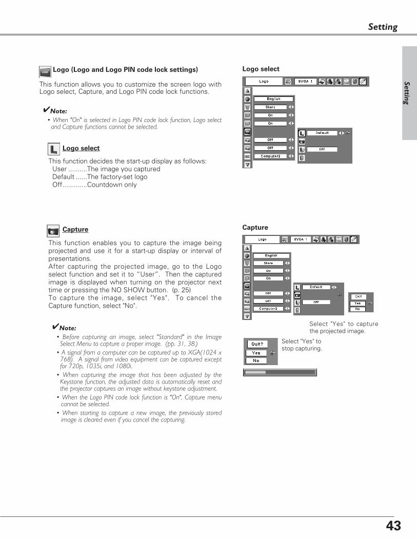
Capture
This function enables you to capture the image beingprojected and use it for a start-up display or interval ofpresentations. After capturing the projected image, go to the Logoselect function and set it to “User”. Then the capturedimage is displayed when turning on the projector nexttime or pressing the NO SHOW button. (p. 25) To capture the image, select "Yes". To cancel theCapture function, select "No".
✔Note:• Before capturing an image, select "Standard" in the Image
Select Menu to capture a proper image. (pp. 31, 38.)• A signal from a computer can be captured up to XGA(1024 x
768). A signal from video equipment can be captured exceptfor 720p, 1035i, and 1080i.
• When capturing the image that has been adjusted by theKeystone function, the adjusted data is automatically reset andthe projector captures an image without keystone adjustment.
• When the Logo PIN code lock function is "On", Capture menucannot be selected.
• When starting to capture a new image, the previously storedimage is cleared even if you cancel the capturing.
Select "Yes" to capturethe projected image.
Select "Yes" tostop capturing.
Capture
Logo select
This function decides the start-up display as follows:User ..........The image you captured Default ......The factory-set logoOff.............Countdown only
Logo (Logo and Logo PIN code lock settings)
This function allows you to customize the screen logo withLogo select, Capture, and Logo PIN code lock functions.
Logo select
✔Note:• When "On" is selected in Logo PIN code lock function, Logo select
and Capture functions cannot be selected.
Setting

44
Logo PIN code lock Dialog Box
Quit
Pointer
Enter a Logo PIN code
Select a number by pressing the Point 7 8 buttons andfix the number with the SELECT button. The numberchanges to "✳". If you fixed an incorrect number, movethe pointer to "Set" or "Clear" once by pressing the Pointd button, then return to "Logo PIN code". Enter thecorrect number again.
Repeat this step to complete entering a four-digitnumber.
When the four-digit number is fixed, the pointerautomatically moves to "Set". Press the SELECT buttonso that you can change the Logo PIN code lock setting.
If you entered an incorrect Logo PIN code, "Logo PINcode", the numbers (✳✳✳✳) turn red and disappear.Enter a correct Logo PIN code all over again.
After a correct Logo PIN code is entered, the following dialog box appears.
Select On/Off by pressing the Point 7 8
buttons or change the Logo PIN code.Change the Logo PIN code
Logo PIN code can be changed to your desired four-digitnumber. Select "Logo PIN code change" with the Pointd button and press the SELECT button. Set a new LogoPIN code.
Be sure to note the new Logo PIN code and keep it athand. If you lost the number, you could no longerchange the Logo PIN code setting. For details on PINcode setting, refer to relevant instructions of the PINcode lock function on pp. 47, 48.
Logo PIN code lock
This function prevents an unauthorized person fromchanging the screen logo.
Off .......the screen logo can be changed freely fromthe Logo select menu. (p. 43)
On .......the screen logo cannot be changed withoutthe Logo PIN code.
If you want to change the Logo PIN code lock setting,enter a Logo PIN code along the following steps. Theinitial Logo PIN code is set "4321" at the factory.
Logo PIN code lock
Setting
CAUTION:
WHEN YOU HAVE CHANGED THE LOGO PIN CODE,
TAKE A MEMO AND KEEP IT SECURELY. SHOULD
THE LOGO PIN CODE BE LOST OR FORGOTTEN, THE
PROJECTOR CAN NO LONGER BE OPERATED.

45
Setting
Ceiling
Rear
Ceiling
When this function is “On,” the picture is top/bottom andleft/right reversed. This function is used to project theimage from a ceiling mounting the projector.
Rear
When this function is “On,” the picture is left/rightreversed. This function is used to project the image to arear projection screen.
Terminal
The COMPUTER IN 2/MONITOR OUT terminal on the backof the projector is switchable for computer input or monitoroutput. (p. 9) Select Computer 2 or Monitor Out with thePoint 7 8 buttons.
Computer 2 . . . .computer inputMonitor Out . . .monitor out
Terminal function is not available when selecting Computer2 to the input source. Change the input source to theothers (Computer1 or Video) so that the Terminal function isavailable. (pp. 26, 35, 36)
Power management
Time left before Lamp is off.
Press the SELECT buttonat Power management and this box appears. Selectone of three settings withthe Point 7 8 buttons, and go to the timer with thePoint ed buttons and settime with the Point 7 8
buttons.
Power management
For reducing power consumption as well as maintaining thelamp life, the Power management function turns off theprojection lamp when the input signal is interrupted and nobutton is pressed for a certain period.When the input signal is interrupted and no button ispressed for 30 seconds or more, the timer display with "Nosignal" appears. The countdown starts to turn off the lamp.
Select one of the operations.
Ready . . . . . . . When the lamp has been fully cooled down, the POWER indicator changes togreen blinking. In this condition, theprojection lamp is turned on if the inputsignal is reconnected or any button on theremote control is pressed.
Shut down. . . When the lamp has been fully cooleddown, the power is turned off.
Off. . . . . . . . . . Power management function is off.
Then set the countdown timer with the Point 7 8buttons.
Setting

46
Setting
On start
When this function is “On”, the projector is automaticallyturned on just by connecting the AC power cord to anoutlet.
✔Note:• Be sure to turn the projector off properly (see “Turning Off the
Projector” on p. 20). If the projector is turned off in the incorrectsequence, the On start function does not operate properly.
Lamp control
Remote control
This projector provides two different remote control codes;the factory-set, initial code (Code 1) and the secondary code(Code 2). This switching function prevents remote controlinterference when operating several projectors or videoequipment at the same time. When operating the projector in “Code 2”, both theprojector and the remote control must be switched to“Code 2”.
To change the code for the projector;
Select either “Code 1” or “Code 2” in this Setting Menu.
To change the code for the remote control;
Press and hold both the MENU and IMAGE buttonstogether for 10 seconds or more. After changing the code,make sure the remote control operates properly.
Remote control
Press and holdMENU andIMAGE buttonsfor 10 seconds ormore.
You can change the brightness of the screen.
Normal ....Normal brightness Auto ........Brightness according with the input signal Eco ..........Lower brightness reduces the lamp power
consumption and extends thelamp life.
On start
✔Note:• When different codes are set on the projector and on the remote
control, any operation cannot be made. In that case, switch thecode on the remote control to fit the code on the projector.
• When the batteries of the remote control are replaced, the remotecontrol code automatically returns to the initial code (Code 1).

47
Setting
Security (Alarm and PIN code lock settings)
This function allows you to use PIN code lock and Alarmfunction to set the security for the projector operation.
PIN code lock
This function prevents the projector from being operatedby an unauthorized person and provides the followingsettings for security options.
Off........The projector is not locked with the PIN code.On1.....Require to enter the PIN code every time
turning on the projector. On2......Require to enter the PIN code to operate the
projector once the power cord is disconnected;as long as the AC power cord is connected, theprojector can be operated without the PINcode.
Whenever to change the PIN code lock setting or thePIN code (the four-digit number), you are required toenter the PIN code. "1234" is set as the initial PIN codeat the factory.
When the projector is lockedwith the PIN code, the PINcode lock mark appears on the menu bar.
PIN code lock
Setting
Select Off, On1, or On2 with the Point 7 8 buttons andthen move the red framed pointer to "Quit" with thePoint d button. Press the SELECT button to close thedialog box.
To Change the PIN code lock setting
Enter a PIN code
Select a number by pressing the Point 7 8 buttons andfix the number with the SELECT button. The numberchanges to "✳". If you fixed an incorrect number, movethe pointer to "Set" or "Clear" once by pressing the Pointd button, then return to "PIN code". Enter the correctnumber again.Repeat this step to complete entering a four-digitnumber.
When the four-digit number is fixed, the pointerautomatically moves to "Set". Press the SELECT buttonso that you can change the following PIN code locksettings.
If you entered an incorrect PIN code, "PIN code" and thenumber (✳✳✳✳) turn red and disappear. Enter a correctPIN code all over again.
Enter a PIN code
Pointer
The input numbers changeto “✳” for security.
When the pointerautomatically moves to "Set",press the SELECT button.
Quit

48
Setting
The PIN code can be changed to your desired four-digitnumber.Select "PIN code change" with the Point d button, andpress the SELECT button to display the New PIN codeinput dialog box.
Select a number with the Point 7 8 buttons and fix thenumber with the SELECT button. Repeat it to completeentering a four-digit number. When the four-digitnumber is fixed, the pointer automatically moves to"Set". Then press the SELECT button.
To Change the PIN code
Change the PIN code
Select PIN code change andpress the SELECT button.The New PIN code inputdialog box appears.
The entered numbers aredisplayed for confirmation.
Change the PIN code lock setting
Select a desiredsetting with thePoint 7 8 buttons.
CAUTION:
WHEN YOU HAVE CHANGED THE PIN CODE, TAKE
A MEMO AND KEEP IT SECURELY. IF YOU FORGET
YOUR PIN CODE, THE PROJECTOR CAN NO
LONGER BE STARTED.
Alarm
Make some settings for the Antitheft alarm function.(pp. 50-52)
Press the SELECT button at Alarm icon to display theAlarm setting box.
When the Antitheft alarm function is set, "On" isdisplayed. When the function is released, "Off" isdisplayed. See p. 50 to set or release this function.
Select Alarm volume, Sensitivity or Ringing time withthe Point ed buttons, and set each item with the Point7 8 buttons.
Alarm volumeSmallMediumLarge
SensitivityLow ..................Less sensitive Medium ...........Normal sensitivityHigh .................Highly sensitive (default setting)
Ringing time10 seconds ......Default setting.
Ring about 10 seconds.60 seconds ......Ring about 60 seconds.Long time.........Ring until the end of the battery life.
Alarm
When Antitheft alarm is"On", the battery is notinstalled or coming to theend or its life, Alarm iconbecomes gray and cannotbe selected.
Press the SELECT button at the Alarmicon to display the Alarm setting box.
✔Note:• The Alarm icon becomes gray and cannot be
selected when the Antitheft alarm function is"On", a battery is not installed, or the battery iscoming to the end of its life.
• While the Alarm icon is selected, the Antitheftalarm setting buttons on the side panel cannotbe operated.
• When selecting "Long time" in Ringing time, thelength of alarm ringing time differs depending onthe battery life.
Set Sensitivity orRinging time withthe Point 7 8
buttons.
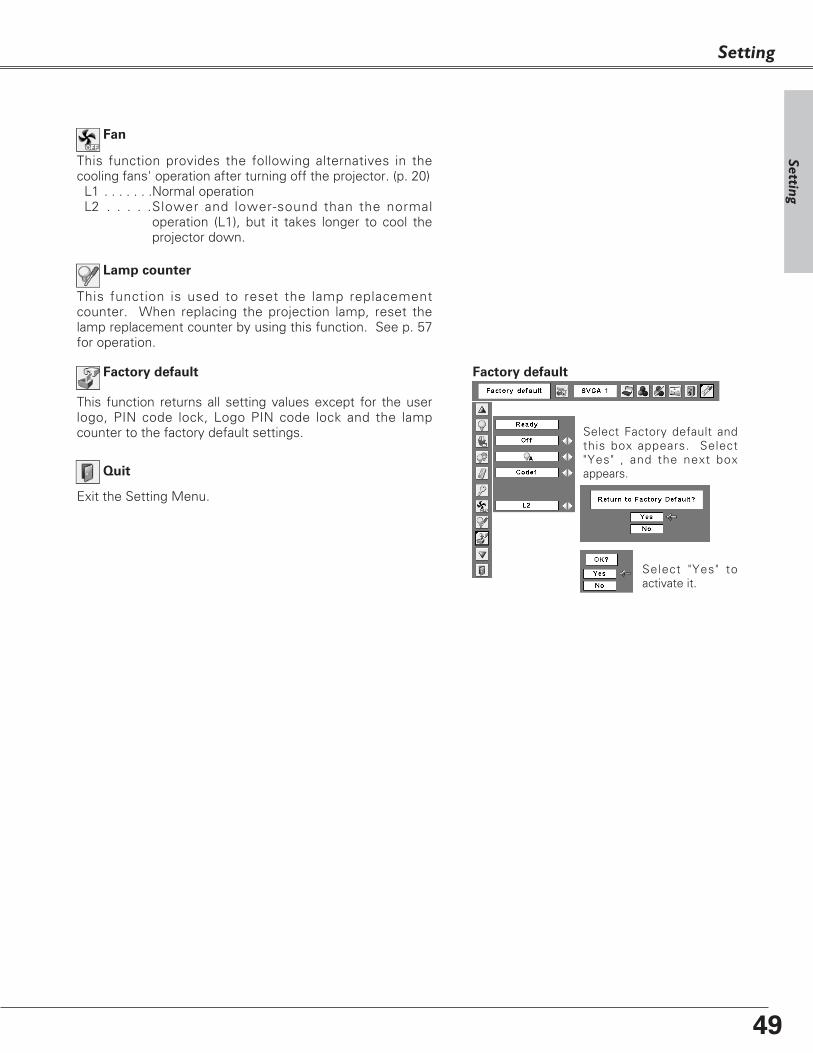
49
This function is used to reset the lamp replacementcounter. When replacing the projection lamp, reset thelamp replacement counter by using this function. See p. 57for operation.
Lamp counter
Factory default
This function returns all setting values except for the userlogo, PIN code lock, Logo PIN code lock and the lampcounter to the factory default settings. Select Factory default and
this box appears. Select"Yes" , and the next boxappears.
Factory default
Select "Yes" toactivate it.
This function provides the following alternatives in thecooling fans' operation after turning off the projector. (p. 20)
L1 . . . . . . .Normal operationL2 . . . . .Slower and lower-sound than the normal
operation (L1), but it takes longer to cool theprojector down.
Fan
Setting
Exit the Setting Menu.
Quit
Setting

50
How to Use the Antitheft Alarm Function
Antitheft Alarm Function
The Antitheft alarm function is to prevent the projector from being stolen. With this function on, the alarm ringswhen an unauthorized person tries to move the projector.
Press the F button twice to turn the alarm function on. TheALARM indicator blinks for a few seconds and the projectorenters the warning mode.
While the Antitheft alarm function is on, the projector emitsa low-pitched sound when detecting a vibration. When the projector does not detect a vibration for a fewseconds after the sound, it goes back to the warning mode.When the projector detects more vibrations after the low-pitched sound, the alarm starts ringing.
Set the alarm
Release the alarm setting
✔Note:• This function is not a guarantee against stealing.• The alarm does not ring while the AC power cord is connected
even if the projector detects vibrations. • Pressing the button is always accompanied by a sound. If any
sound is not produced after pressing the button, you need to pressit again.
Side Control
ALARM
indicator
F button button 1, 2, 3
Set and release the Antitheft alarm function
✔Note:• You can test the alarming sound without setting the alarm. Press
and hold the F button then the alarm starts ringing. The length ofthe ringing time is what you set on the "Ringing time". (p. 48)
• If you want to stop the alarm while it is ringing, insert the ACpower cord or press the F button and enter the four-digit PIN code.
Before operating the Antitheft alarm function, install abattery in the projector. (see p. 52 for installation)
Install a battery
1 Press the F button and enter the four-digit PIN codewithin about 10 seconds. (The default PIN code is"1111".) When the alarm is released, you hear high-pitched confirmation sound.
When entering an incorrect PIN code, you hear low-pitched sound. If you enter an incorrect PIN code 3times, the alarm starts ringing.

51
Antitheft Alarm Function
CAUTION:
WHEN YOU HAVE CHANGED THE PIN CODE, WRITE
DOWN THE NEW PIN CODE AND KEEP IT SECURELY.
IF YOU FORGET YOUR PIN CODE, SOME SETTINGS OF
THE ALARM FUNCTION CAN NO LONGER BE
CHANGED.
Change the PIN code
Press the F button and enter the four-digit PIN codewithin about 10 seconds. The ALARM indicator blinksred for a few seconds and high-pitched confirmationsound is made.
Settings
Reset the settings
Select Factory default in the Setting menu to reset thesettings for the Antitheft alarm function.
Side Control
Antitheft A
larm Function
1
2 While the indicator is blinking, enter new PIN codethen you will hear the high-pitched confirmation soundand the ALARM indicator is off.
When typing an incorrect PIN code, you will hear low-pitched sound. If you enter incorrect PIN codes 3times, the alarm starts ringing.
A PIN code for Antitheft alarm function is thecombination of 1, 2, or 3. Enter the PIN code with thebutton 1, 2, and 3. The default PIN code is set as"1111".
✔Note:• This is effective only when the Antitheft alarm setting is released.• You can make some more detailed settings. (p. 48)
ALARM
indicator
F button button 1, 2, 3

52
Antitheft Alarm Function
How to install the battery
To use the Antitheft alarm function, you need to install abattery. (Use a CR2 3V lithium battery.)
To install the battery, remove the screw and open thebattery cover on the bottom of the projector.When the battery is installed properly, the ALARM indicatorblinks for about 10 seconds.After placing the battery, put the cover back and secure itwith the screw.
When the life of the battery draws to an end, the ALARMindicator flashes and warning sound is made at someintervals.Replace the battery with following the procedures above.
✔Note:• Even after changing the battery, the PIN code you have changed
and settings you have made are effective.• When changing the battery, set the Antitheft alarm function off.
Otherwise the alarm starts ringing when you try to open the batterycover.
Loosen the screw andopen the battery cover.
Install the battery then replace thebattery cover and secure it with thescrew.
Screw
To insure safe operation, please observe the following precautions:● Do not keep the battery mixing with wire or metal products to avoid causing a short.● Keep the battery away from babies and children to prevent them from swallowing it. ● Do not charge the battery.● Do not disassemble, or apply pressure to transform the battery.● Avoid contact with water or liquid.● Do not expose to moisture or heat.● If the battery has leaked, carefully wipe the battery compartment clean and install new battery.● Do not replace the battery with an incorrect type or in an incorrect direction. ● Dispose of used battery after insulating the battery with putting insulating tape on either or both
sides on the top/bottom of the battery.● Dispose of used battery with following local regulations.

53
The WARNING indicator shows the state of the function which protects the projector. Check the state of theWARNING indicator and the POWER indicator to take proper maintenance.
Top Control
Warning Indicator
The projector is shut down and the WARNINGindicator is blinking red.
When the temperature inside the projector reaches acertain level, the projector is automatically shut down toavoid overheating. The POWER indicator is blinking whilethe projector is being cooled down. When the projector hascooled down enough (to its normal operating temperature),it can be turned on again by pressing the POWER ON-OFFbutton.
✔Note:• After the temperature inside the projector returns to normal, the
WARNING indicator still continues to blink. When the projector is turned on again, the WARNING indicator stops blinking.
Then check the matters below:
– Did you provide appropriate space for the projector to be ventilated? Check the installing condition to see ifventilation slots are not blocked.
– Is the projector not installed near the ventilation duct ofair-conditioning equipment which may be hot? Install theprojector away from the venti lation duct of air-conditioning equipment.
– Are the air filters clean? Clean the air filters periodically.(p. 54)
WARNINGemit a red lightTop ControlThe projector is shut down and the WARNING
indicator emits a red light.
When the projector detects an abnormal condition, it isautomatically shut down to protect the inside and theWARNING indicator is red. In this case, disconnect the ACpower cord and reconnect it, and then turn the projector ononce again for check. If the projector cannot be turned onand the WARNING indicator emits a red light, disconnectthe AC power cord and contact the service station for checkand repair.
CAUTION
DO NOT LEAVE THE PROJECTOR WITH THE ACPOWER CORD CONNECTED UNDER THEABNORMAL CONDITION. IT MAY RESULT INFIRE OR ELECTRIC SHOCK.
Maintenance and Cleaning
REPLACEPOWER WARNING LAMP
REPLACEPOWER WARNING LAMP
WARNINGblinking red
Maintenance &
Cleaning

54
Maintenance and Cleaning
Turn off the projector, and disconnect the AC powercord from the AC outlet.
Turn over the projector and remove the air filters bypulling the latches upward.
1
2
Air filters prevent dust from accumulating on the optical elements inside the projector. Should the air filtersbecome clogged with dust particles, it reduces cooling fans’ effectiveness and may result in internal heat buildup and adversely affect the life of the projector. Clean the air filters following the steps below.
Clean the air filters with a brush or rinse them softly.3When cleaning the air filters by rinsing, dry them well.Replace the air filters properly. Make sure that the airfilters are fully inserted.
4
CAUTION
Do not operate the projector with the air filtersremoved. Dust may accumulate on the opticalelements degrading picture quality.Do not put small parts into the air intake vents. Itmay result in malfunction of the projector.
RECOMMENDATIONWe recommend avoiding dusty/smoky environmentswhen operating the projector. Usage in theseenvironments may cause poor image quality.
When using the projector under dusty or smoky conditions,dust may accumulate on a lens, LCD panels, or opticalelements inside the projector. This condition may degradethe quality of a projected image.When the symptoms above are noticed, contact yourauthorized dealer or service station for proper cleaning.
✔Note:• When reinserting this air filter, be sure that the
slit part is facing the outer side.
Air filtersPull up and remove.
Attaching the Lens Cover
When moving the projector or the projector is not in use,replace the lens cover.
1
2
Thread the string through the hole on the lens coverand then tie a knot.
Thread the other end of the string through the hole onthe bottom of the projector. Then pass the lens coverthrough the resulting loop and pull it to tighten theknot.
2
1
Cleaning the Air Filters

55
Maintenance and Cleaning
Disconnect the AC power cord before cleaning.
When the projector is not in use, replace the lenscover.
1
3
2
Cleaning the Projector Cabinet
Disconnect the AC power cord before cleaning.1
Gently wipe the projector body with a soft, drycleaning cloth. When it is heavily soiled, use a smallamount of mild detergent and finish with the cleaningcloth. Avoid excessive use of cleaner. Abrasivecleaners, solvents, or other harsh chemicals mightscratch the surface.
2
Follow these steps to clean the projector cabinet.
When the projector is not in use, put the projector inan appropriate case to avoid dust and being scratched.
3
First, remove the dust with a blower.Then gently wipe the lens surface. Use a lenscleaning paper moistened with methyl alcohol(methanol). Avoid excessive use of cleaner.Do not use abrasive cleaners, solvents, or other harshchemical cleaners not to damage the lens.
Cleaning the Projection Lens
Maintenance &
Cleaning
CAUTION
This projector is equipped with a plastic lens. Do not rub with hard fiber cloth or do not hit the lens with something hard to prevent the lens from scratching. Do not use chemical cleaner (liquid and solid) avoid deteriorating the lens.

56
Maintenance and Cleaning
Follow these steps to replace the lamp.
Lamp
ORDER REPLACEMENT LAMP
Replacement lamp can be ordered through your dealer. When ordering a projection lamp, give the followinginformation to the dealer.
● Model No. of your projector : PLC-XE40
● Replacement Lamp Type No. : POA-LMP90 (Service Parts No. 610 323 0726)
For continued safety, replace with a lamp of thesame type. Do not drop a lamp or touch a glassbulb! The glass can shatter and may cause injury.
Allow a projector to cool, for at least 45 minutesbefore you open the Lamp cover. The inside ofthe projector can become very hot.
CAUTION
Screw
Turn off the projector and disconnect the AC powercord. Allow the projector to cool for at least 45minutes.
Remove 2 screws of the lamp with a screwdriver andpull out the lamp by grasping the handle.
1
3
Replace the lamp with a new one and tighten the 2screws back into position. Make sure that the lamp isset properly. Replace the lamp cover and tighten thescrew.
4
Remove the screw with a screwdriver, and removethe lamp cover.
2
Connect the AC power cord to the projector and turnon the projector.
6 Reset the lamp replacement counter.
See “Lamp Replacement Counter” on the next page .
5 Handle
Screw
CAUTION
ScrewLamp Cover
When the life of the projection lamp of this projector drawsto an end, the LAMP REPLACE indicator emits a yellowlight. If this indicator lights yellow, replace the lamp with anew one promptly.
Top Control
Lamp Replacement
WARNING:
TURN OFF THE UV LAMP BEFOREOPENING THE LAMP COVER
REPLACEPOWER WARNING LAMP
This indicator is yellow whenthe life of the projection lampdraws to an end.

57
Maintenance and Cleaning
Be sure to reset the Lamp replacement counter after the lamp is replaced. When the Lamp replacementcounter is reset, the LAMP REPLACE indicator stops lighting.
Turn the projector on, press the MENU button todisplay the On-Screen Menu. Press the Point 7 8
buttons to move the red framed pointer to the SettingMenu icon.
Press the Point ed buttons to move the red framedpointer to the Lamp counter function and then pressthe SELECT button. The first dialog box appears andshows the total accumulated time of the lamp usageand the reset option. If you select "Reset", a "Lampreplacement counter Reset?" appears. Select "Yes" tocontinue.
1
2
Another confirmation dialog box appears, select "Yes"to reset the Lamp replacement counter.
3
This projector uses a high-pressure lamp which must be handled carefully and properly. Improper handling may result in accidents, injury, or create a fire hazard.
● Lamp life may differ from lamp to lamp and according to the environment of use. There is noguarantee of the same life for each lamp. Some lamps may fail or terminate their life in a shorterperiod of time than other similar lamps.
● If the projector indicates that the lamp should be replaced, i.e., if the LAMP REPLACE indicator lightsup, replace the lamp with a new one IMMEDIATELY after the projector has cooled down. ( Follow carefully the instructions in the Lamp Replacement section of this manual.) Continuous use ofthe lamp with the LAMP REPLACE indicator lighted may increase the risk of lamp explosion.
● A Lamp may explode as a result of vibration, shock or degradation as a result of hours of use as itslifetime draws to an end. Risk of explosion may differ according to the environment or conditions inwhich the projector and lamp are being used.
IF A LAMP EXPLODES, THE FOLLOWING SAFETY PRECAUTIONS SHOULD BE TAKEN.
If a lamp explodes, disconnect the projector’s AC plug from the AC outlet immediately. Contact anauthorized service station for a checkup of the unit and replacement of the lamp. Additionally, checkcarefully to ensure that there are no broken shards or pieces of glass around the projector or coming outfrom the cooling air circulation holes. Any broken shards found should be cleaned up carefully. No oneshould check the inside of the projector except those who are authorized trained technicians and who arefamiliar with projector service. Inappropriate attempts to service the unit by anyone, especially thosewho are not appropriately trained to do so, may result in an accident or injury caused by pieces of brokenglass.
LAMP HANDLING PRECAUTIONS
Lamp Replacement Counter
✔Note:• Do not reset the Lamp replacement counter without
implementation of lamp replacement. Be sure to reset the Lamp replacement counter only after replacing the lamp.
Select "Yes",then another confirmation boxappears.
Select "Yes" again to reset the lamp counter.
To reset the lamp counter, move the pointer to Resetand then press the SELECT button.“Lamp replacementcounter Reset?” dialog boxis displayed.
Maintenance &
Cleaning

58
Troubleshooting
Before calling your dealer or service center for assistance, check the items below once again.
–Make sure you have properly connected the projector to peripheral equipment as described on pp.16-18. –Make sure all equipment is connected to AC outlet and the power is turned on.–When you operate the projector with a computer and it does not project an image, restart the computer.
Appendix
Problem: – Solutions
No power – Plug the power cord of the projector into the AC outlet.– See if the POWER indicator lights red.– Wait 90-120 seconds after the projector is turned off when turning
the projector back on. The projector can be turned on after the POWER indicator turns red. (See on p. 20)
– Check the WARNING indicator. If the WARNING indicator lights red,the projector cannot be turned on. (See on p. 53)
– Check the projection lamp. (See p. 56)
Image is out of focus. – Adjust focus of the projector. (See p. 23)– Provide proper distance between the projector and the projection
screen. (See p. 14)– Check the projection lens to see if it needs cleaning. (See p. 55)– Moving the projector from a cool to a warm place may result in
moisture condensation on the projection lens. In such cases, leave the projector off and wait until condensation evaporates.
No image – Check the connection between your computer or video equipment and the projector. (See pp. 16–18)
– See if the input signal is correctly output from your computer. Somelaptop computers may need to change the setting for monitor outputwhen connecting to a projector. See your computer’s instruction manual for the setting.
– It takes about 30 seconds to display an image after turning on the projector.See if the selected system is corresponding with your computer or video equipment. (See pp. 27 and 37)
– Select correct input source once again through menu operation.(See pp. 26 ,35 and 36)
– Make sure the temperature is not out of the specified Operating Temperature (41 ˚F ~ 95 ˚F (5 ˚C ~ 35 ˚C)) .
Image is Left/Right reversed. – Check the Ceiling / Rear function. (See p. 45)Image is Top/Bottom reversed. – Check the Ceiling function. (See p. 45)
No sound – Check audio cable connection from audio input source.– Adjust the audio source.– Press the Volume+ button. (See p. 24)– Press the Mute button. (See p. 24)

59
Appendix
The CE Mark is a Directive conformity mark of the European Community (EC).
Some displays are not seen –Check the Display function. (See p. 42)during the operation.
PIN code dialog box appears at start-up. –PIN code lock is being set. Enter a PIN code (1234 or numbers you have set). (See p. 19, 47, 48)
Computer 2 cannot be selected. –Select Computer 2 at the Terminal function. (See p. 45)
The Terminal function cannot be selected. –The Terminal function cannot be selected after Computer 2 is selected. Select other input source such as Computer 1 or Video with the COMPUTER button or the VIDEO button on the remote control so that the Terminal function can be selected.
The Remote Control does not work. –Check the batteries.–Make sure no obstruction is between the projector and the remote control.
–Make sure you are not too far from the projector when using the remote control. Maximum operating range is 16.4’ (5m).
–Make sure the code of the remote control is conformed to the projector. (See p. 46)
Cooling fans are still running after –This is normal condition. Fans keep running for a certain timethe AC plug is disconnected. even after disconnecting the AC plug.
WARNING :
High voltages are used to operate this projector. Do not attempt to open the cabinet.
If problems still persist after following all operating instructions, contact the dealer where you purchased theprojector or the service center. Give the model number and explain about the problem. We will advise youhow to obtain service.
Pixelworks ICs used.
Ap
pendix

60
Appendix
Menu Tree
Mode 1Mode 2SVGA 1- - - -
Computer Input
✽Systems displayed in the System Menu varydepending on an input signal.
Computer Input / Video Input
Sound
Volume
Mute
Quit
On / OffSound 0 - 63
Input
Computer 2
Video Auto
Go to System (3)
Go to System (3)
Video
Go to System (3)
✽N/A - - - not applicable
Go to System (1)
Go to System (2)
N/A
S-Video
RGB( Scart )
Quit
Quit
System (1)
RGBComputer 1
Component
Auto PC Adj.
Total dotsHorizontalVertical
Display area HDisplay area VReset
Dynamic
RealBlackboard(Green)Image 1Image 2Image 3
Image Adjust ContrastBrightnessColor temp.
Red
Gamma
Store
Quit
NormalTrueWideFull screen
Digital zoom +
0 - 630 - 63
PC Adjust
Mode 1
Mode 2Mode 3Mode 4Mode 5
Image Select
High
0 - 63
0 - 15
Image 1Image 2Image 3Image 4
Screen
Quit
Yes / No
Reset Yes / No
Sharpness 0 - 15
Image 4
Standard
Mode 1Mode 2Mode 3Mode 4Mode 5Quit
H-sync freq.V-sync freq.Quit
ClampCurrent mode
Digital zoom –
GreenBlue
0 - 630 - 63
Store
Mode free
Quit
MidLowXLow
Quit
Adj.
Fine sync. 0 - 31
Custom Scale H / VH&VPosition H / VCommonResetQuit
Yes / NoYes / No
On / Off

61
Appendix
AutoPALSECAMNTSCNTSC 4.43PAL-MPAL-N
Video Input
Auto1080i1035i720p575p480p575i480i
Dynamic
CinemaBlackboard(Green)Image 1Image 2Image 3
Setting
Image Select
System (2)
System (3)
Image 4
LanguageSetting EnglishGermanFrenchItalianSpanishPortugueseDutchSwedish
ChineseKoreanJapanese
On / OffOn / Countdown off / Off
Logo select
On / OffOn / Off
Off
On / OffNormal / Auto / Eco
Code 1 / Code 2
KeystoneBlue backDisplay
Logo
CeilingRear
Power management
On startLamp control
Remote control
Quit
Russian
ReadyShut down
Quit
Timer(1-30 Min)Quit
Factory default
L1 / L2Fan
Quit
Standard
Finnish
HungarianRomanian
Polish
Yes / No
Store / Reset
Quit
Off
UserCapture
Yes / No
OffOnPIN code change
Logo PIN code lockLogo PIN code entry
Quit
PIN code lock entryOn / OffPIN code changeQuit
Alarm
Default
SensitivityRinging timeQuit
Off
On
Computer 2 /Monitor outTerminal
ResetQuit
Ap
pendix
PIN code lockSecurity
Quit
NormalWide
0 - 630 - 63
Off
Image Adjust ContrastBrightnessColorTint
RedGreenBlueSharpness
ResetStore
Gamma
Progressive
0 - 630 - 630 - 630 - 15 0 - 15
Image 1
Screen
Yes / No
Quit
Color temp.
OffNoise reductionL1L2
HighMidLowXLow
0 - 630 - 63
Image 2Image 3Image 4
L2L1
Adj.
Film
Custom Scale H / VH&VPosition H / VCommonResetQuit
Yes / NoYes / No
On / Off
Alarm volume
Lamp counter Hour(s)
Small / Medium / Large
Low / Medium / Large
10seconds / 60seconds/ Long time

62
Appendix
Check the indicators for projector condition.
• • • green. • • • red • • • off
• • • blinks green.
✽ When the life of the projection lamp draws to an end, the LAMP REPLACE indicator lights yellow.When this indicator lights yellow, replace the projection lamp with a new one promptly. Reset the lampreplacement counter after replacement of the lamp. See pp. 56 and 57.
Indicators and Projector Condition
• • • blinks red.
The projector is off. (The AC power cord is unplugged.)
The projector is preparing for stand-by or the projection lamp isbeing cooled down. The projector cannot be turned on until coolingis completed.
The temperature inside the projector is abnormally high. Theprojector cannot be turned on. When the projector is cooled downenough and the temperature returns to normal, the POWERindicator emits a red light and the projector can be turned on. (TheWARNING indicator keeps blinking.) Check and clean the air filters.
Projector Condition
The projector is ready to be turned on with the POWER ON-OFFbutton.
POWERred/green
Indicators
LAMPREPLACE
yellow
WARNING red
The projector detects an abnormal condition and cannot be turnedon. Unplug the AC power cord and plug it again to turn on theprojector. If the projector is turned off again, disconnect the ACpower cord and contact the dealer or the service center for serviceand checkup. Do not leave the projector on. It may cause anelectric shock or a fire hazard.
✽
✽
✽
✽
✽
The projector is operating normally.
The projector is in the Power management mode.
✽
✽
The projector has been cooled down enough and the temperaturereturns to normal. When turning on the projector, the WARNINGindicator stops blinking. Check and clean the air filters.

63
Appendix
Compatible Computer Specifications
Basically this projector can accept the signal from all computers with the V, H-Frequency below mentionedand less than 140 MHz of Dot Clock.
When selecting these modes, PC adjustment can be limited.
ON-SCREEN
DISPLAYRESOLUTION
H-Freq.
(kHz)
V-Freq.
(Hz)
VGA 1 640 x 480 31.47 59.88VGA 2 720 x 400 31.47 70.09VGA 3 640 x 400 31.47 70.09VGA 4 640 x 480 37.86 74.38VGA 5 640 x 480 37.86 72.81VGA 6 640 x 480 37.50 75.00
MAC LC13 640 x 480 34.97 66.60MAC 13 640 x 480 35.00 66.67
MAC 16 832 x 624 49.72 74.55
MAC 19 1024 x 768 60.24 75.08
SXGA 1 1152 x 864 64.20 70.40
SVGA 1 800 x 600 35.156 56.25SVGA 2 800 x 600 37.88 60.32SVGA 3 800 x 600 46.875 75.00SVGA 4 800 x 600 53.674 85.06SVGA 5 800 x 600 48.08 72.19SVGA 6 800 x 600 37.90 61.03SVGA 7 800 x 600 34.50 55.38SVGA 8 800 x 600 38.00 60.51SVGA 9 800 x 600 38.60 60.31
SVGA 11 800 x 600 38.00 60.51
ON-SCREEN
DISPLAYRESOLUTION
H-Freq.
(kHz)
V-Freq.
(Hz)
XGA 10 1024 x 768XGA 11 1024 x 768XGA 12 1024 x 768XGA 13 1024 x 768
62.04 77.07
XGA 14 1024 x 768
61.00 75.70
XGA 15 1024 x 768
35.522 86.96(Interlace)
46.90 58.20
XGA 8 1024 x 768
47.00 58.30
XGA 9 1024 x 768
58.03 72.00
SXGA 4 1280 x 1024
63.48 79.3536.00 87.17
(Interlace)
63.34 59.98SXGA 5 1280 x 1024SXGA 6 1280 x 1024SXGA 7 1280 x 1024
63.74 60.0171.69 67.19
SXGA 10 1280 x 960
81.13 76.107
60.00 60.00
XGA 1 1024 x 768
XGA 4 1024 x 768
48.36 60.00
XGA 6 1024 x 768XGA 7 1024 x 768
56.476 70.07
48.50 60.0244.00 54.58
SXGA 8 1280 x 1024SXGA 9 1280 x 1024
63.98 60.0279.976 75.025
XGA 5 1024 x 768 60.31 74.92
VGA 7 640 x 480 43.269 85.00
575i –––––––– 15.625 50.00(Interlace)
480i –––––––– 15.734 60.00(Interlace)
SXGA 12 1152 x 900 71.40 75.60SXGA 11 1152 x 900 61.20 65.20
SVGA 10 800 x 600 32.70 51.09
SXGA 13 1280 x 1024 50.00 86.00(Interlace)
SXGA 2 1280 x 1024 62.50 58.60SXGA 3 1280 x 1024 63.90 60.00
XGA 2 1024 x 768 68.677 84.997XGA 3 1024 x 768 60.023 75.03
SXGA 18 1280 x 1024 46.43 86.70(Interlace)
SXGA 19 1280 x 1024 63.79 60.18
SXGA 14 1280 x 1024SXGA 15 1280 x 1024SXGA 16 1280 x 1024SXGA 17 1152 x 900
50.00 94.00(Interlace)
63.37 60.0176.97 72.0061.85 66.00
MAC 1280 x 960 75.00 75.08MAC 1280 x 1024480p ––––––––
575p ––––––––
80.00 75.0831.47 59.88
1080i ––––––––
31.25 50.00
33.75 60.00(Interlace)
720p ––––––––
1035i ––––––––
45.00 60.0033.75 60.00
(Interlace)
1080i –––––––– 28.125 50.00(Interlace)
SXGA 21 1400 x 1050 63.979 60.190
MAC21 1152 x 870 68.68 75.06
UXGA 4 1600 x 1200 93.75 75.00
WXGA 2 1360 x 768WXGA 3 1376 x 768WXGA 4 1360 x 768UXGA 1 1600 x 1200
47.70 60.00
UXGA 2 1600 x 1200
48.36 60.00
UXGA 3 1600 x 1200
56.16 72.0075.00 60.0081.25 65.00
WXGA 1 1366 x 768
87.5 70.00
48.36 60.00
SXGA 22 1400 x 1050 65.346 60.116SXGA 23 1400 x 1050 65.121 59.902
SXGA 20 1280 x 1024 91.146 85.024
Ap
pendix

64
Appendix
Technical Specifications
Mechanical Information
Projector Type Multi-media ProjectorDimensions (W x H x D) 10.50" x 4.86" x 9.58" (320mm x 148mm x 292mm) (Not including adjustable feet)Net Weight 7.3 lb (3.3kg)Feet Adjustment 0˚ to 10.0˚
Panel Resolution
LCD Panel System 0.6" TFT Active Matrix type, 3 panels Panel Resolution 1,024 x 768 dotsNumber of Pixels 2,359,296 (1,024 x 768 x 3 panels)
Signal Compatibility
Color System PAL, SECAM, NTSC, NTSC4.43, PAL-M, PAL-NHigh Definition TV Signal 480i, 480p, 575i, 575p, 720p, 1035i, and 1080iScanning Frequency H-sync. 15 ~ 100 KHz, V-sync. 50 ~ 100 Hz
Optical Information
Projection Image Size (Diagonal) Adjustable from 60" to 80"Projection Lens F 1.85 lens with f 8.1 mm with manual focusThrow Distance 2.49’ - 3.38’ (0.76m - 1.03m)Projection Lamp 200W
Interface
Video Input Jack RCA Type x 1 S-Video Input Jack Mini DIN 4 pin x 1Audio Input Jacks RCA Type x 2Computer Input 1 / Component Input Terminal Analog RGB (Mini D-sub 15 pin) Terminal X 1Computer Input 2 / Monitor Output Terminal Analog RGB (Mini D-sub 15 pin) Terminal X 1 (In / Out switchable)Computer/ Component Audio Input Jack Mini Jack (stereo) x 1Service Port Connector Mini DIN 8 pin x 1USB Connector USB Series B receptacle x 1Audio Output Jack Mini Jack (stereo) x 1 (Variable)
Audio
Internal Audio Amp 1.0W RMSBuilt-in Speaker 1 speaker, ø1.1" (28mm)
Power
Voltage and Power Consumption AC 100 ~ 120 V (2.9A Max. Ampere), 50 / 60 Hz (The U.S.A and Canada)AC 200 ~ 240 V (1.4 A Max. Ampere), 50 / 60 Hz (Continental Europe and The U.K.)
Operating Environment
Operating Temperature 41 ˚F ~ 95 ˚F (5 ˚C ~ 35 ˚C)Storage Temperature 14 ˚F ~ 140 ˚F (-10˚C ~ 60 ˚C)
Remote Control
Battery AA or LR6 1.5V ALKALINE TYPE x 2Operating Range 16.4’ (5m) / ±30˚Dimensions 1.9”(W) x 0.87”(H) x 5.7”(D) (49mm x 22mm x 145.3mm)Net Weight 3.53 oz (100 g) (including batteries)
Antitheft Alarm
Battery CR2 3V LITHIUM BATTERY x 1

65
Appendix
Model No.
COMPONENT-VGA Cable : POA-CA-COMPVGA
SCART-VGA Cable : POA-CA-SCART
Mini D-sub Extension Cable : KA-MC-DB10
The parts listed below are optionally available. When ordering those parts, give the item name and Model No.to the sales dealer.
Optional Parts
Accessories
Owner's Manual (CD-ROM)Quick Reference GuideAC Power CordRemote Control and BatteriesBattery for Antitheft alarm functionVGA CableLens Cover with String PIN Code LabelAlarm Label
● The specifications are subject to change without notice.● LCD panels are manufactured to the highest possible standards. Even though 99.99% of the pixels are effective, a
tiny fraction of the pixels (0.01% or less) may be ineffective by the characteristics of the LCD panels.
Ap
pendix

66
Appendix
Terminal : Mini DIN 8-PIN
12
3458 7 6
SERVICE PORT CONNECTOR
Vcc- Data+ DataGround
1
2
3
4
USB CONNECTOR (Series B)
2
3 4
1
R X D----------
GNDRTS / CTS
GNDGND
Serial
1
2
3
4
5
6
7
8
COMPUTER INPUT/COMPONENT INPUT/MONITOR OUTPUT TERMINAL (ANALOG)
Terminal : Analog RGB (Mini D-sub 15 pin)
5 123410 9 678
15 14 13 1112
Configurations of Terminals
Red (R/Cr) Input / Output
Ground (Horiz.sync.)
Green (G/Y) Input / Output
-----Blue (B/Cb) Input / Output
Ground (Red)Ground (Green)Ground (Blue)
1
5
2
4
3
6
7
8
-----
Horiz. sync. Input/Output (Composite H/V sync.)
Ground (Vert.sync.)
-----Ground / -----
Vert. sync.-----
9
13
10
12
11
14
15
T X D

67
Appendix
PIN Code Label
Put the label below (supplied) on in a prominent place of theprojector's body while it is locked with a PIN code.
While the projector is locked with the PIN code...
Ap
pendix
Put the label below (supplied) on in a prominent place of theprojector's body while the Antitheft alarm function is set.
While the Antitheft alarm function is set...

Part No. 610 330 0191 (1AA6P1P5190-- LK6A) SANYO Electric Co., Ltd.