multifunctional wing moveables: design of … · 3 multifunctional wing moveables : design of the...
TRANSCRIPT

1
Abstract
The paper describes the concept of the A350XWB wing moveables, providing a functional integration of high-lift with load & cruise performance control. The way forward towards future moveables applications is sketched, e.g. integration of laminarity, novel propulsion concepts, noise control and active flow control as further means for efficiency and minimized environmental impact.
1 Airbus wing moveables up to the A380 All recent civil Airbus aircraft up to A380
[1] represent a high-level evolution of a classical functional breakdown of the wing & moveables devices components. Slats and fowler flaps are used for take-off and landing procedures, spoilers and ailerons for primary flight control aspects. The fixed wing shape is optimized for the target design range of cruise flight.
The design of the wing moveables is highly optimized and the application of modern numerical analysis tools and High-Reynolds-Number windtunnel testing, such as in the European Transonic Windtunnel (ETW) facility has led to a significant improvement of its efficiency. All modern designs therefore usually can exploit sufficient high-lift performance from single slotted flaps while designs from the previous decades required double- or even triple slotted flap designs. The subsequent benefit of these simplifications allowed a significant improvement in terms of complexity, weight and cost.
Fig 1: Airbus A380 in high-lift configuration Based on research studies over the last two
decades new concepts have evolved to approach more enhanced moveables functionalities. The main intent was to exploit further optimization potential by usage of the flap system also in cruise conditions for performance improvement or load control by applying a variable camber function via in-flight adaptation of the cruise wing profile shape from deflection of flaps. The common aspect of most of these concepts was the implementation of usually rather complex add-on devices in addition to the basic high-lift flaps and flight controls.
Successful developments up to large scale demonstrations have taken place, e.g. such as in-flight testing of multifunctional mini Trailing Edge Devices (“miniTEDs”) in the frame of the EU program AWIATOR [2]. The miniTEDs are a highly efficient concept where large effects can be obtained with a small chord device directly on the wing/flap trailing edge. However also these devices require a separate actuation
MULTIFUNCTIONAL WING MOVEABLES: DESIGN OF THE A350XWB AND
THE WAY TO FUTURE CONCEPTS
Daniel Reckzeh AIRBUS
Keywords: wing moveables, high-lift, flight controls
Daniel Reckzeh
2
system which has to be embedded on the primary moveable which carried the miniTED.
Fig 2: “miniTED” (in red) as multifunctional add-on device on the A340 Flaps in Flight Test
Although considered in the development
phase of the A380, the evident benefit of such solutions was outbalanced by the additional complexity and weight. In turn, the preferred approach for cruise wing design was to consider a fixed wing design with larger performance flexibility without too steep shortfalls into the off-design range, however with a drawback on the achievable peak performance.
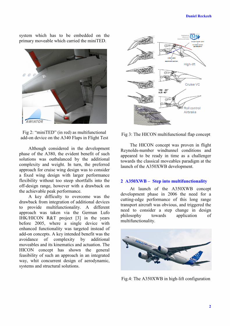
A key difficulty to overcome was the drawback from integration of additional devices to provide multifunctionality. A different approach was taken via the German Lufo IHK/HICON R&T project [3] in the years before 2005, where a single device with enhanced functionality was targeted instead of add-on concepts. A key intended benefit was the avoidance of complexity by additional moveables and its kinematics and actuation. The HICON concept has shown the general feasibility of such an approach in an integrated way, whit concurrent design of aerodynamic, systems and structural solutions.
Fig 3: The HICON multifunctional flap concept The HICON concept was proven in flight
Reynolds-number windtunnel conditions and appeared to be ready in time as a challenger towards the classical moveables paradigm at the launch of the A350XWB development.
2 A350XWB – Step into multifunctionality At launch of the A350XWB concept
development phase in 2006 the need for a cutting-edge performance of this long range transport aircraft was obvious, and triggered the need to consider a step change in design philosophy towards application of multifunctionality.
Fig.4: The A350XWB in high-lift configuration

3
MULTIFUNCTIONAL WING MOVEABLES : DESIGN OF THE A350XWB AND THE WAY TO FUTURE CONCEPTS
Fig 5: Requirements (green), constraints (red) and opportunities (blue) for the A350XWB
moveables integration
2.1 The Adaptive Dropped Hinge Flap The trailing edge flaps concept applied on
the A350XWB provides this integrated approach. Inspired by the HICON multifunctional concept, a contender to the initial baseline A330-like concept was defined. The so called “Adaptive Dropped Hinge Flap” [4] is characterized by the integration of spoiler downward deflection (“droop”) to the fowler flap function, which was qualified in the HICON approach.
Fig.6: Principle of the Adaptive Dropped Hinge
Flap (ADHF) versus a classical fowler flap
The integration of the spoilers, usually only
used as roll-control or lift dumping devices, in the high-lift functionality provided a significant increase in flap efficiency. This benefit could be exploited in various directions: It allowed reduction of the flap chord to mitigate conflicts with the landing gear integration on the inner wing and the rear spar location on the outer wing, as well as reducing the interaction of the flaps with the jet wake of the closed coupled high-bypass engine.
Further, it was the enabler for the simplification of the flap kinematics towards a “simple hinged” deployment concept, as applied on the Airbus A400M. [5] The challenge to design optimized intermediate flap deflections for take-off was solved on A400M by a passive flexible local cambering device on the spoiler trailing edge to control the shape of the flap gap. On the A350XWB flap system, the droop function of the spoilers ensures an optimum flap flow in all intermediate positions and also low flap settings with a completely sealed flap gap.
Fig 7: The A350XWB Adaptive Dropped Hinge Flap in cruise and high-lift settings
The ADHF layout benefits the wing
weight and systems & structures integration aspects, as compared to fowler flap kinematics on track & carriage. Several hundred kilograms wing weight could be saved by reduction of the flap chord in comparison to an equal performing classical layout.
However classical hinged flaps on a kinked trailing edge would result in a large inter-flap

Daniel Reckzeh
4
gap, with visible disadvantages for noise and take-off-drag. To omit this issue, kinematics with streamwise motion movement of the outer flap were invented. While still deploying around hingepoints an additional lateral movement is enabled, that provides good inter-flap sealing throughout the complete deployment range.
3.2. Cruise variable camber and load control Besides the superior high-lift solution this
kinematics concept also led to a straight forward application of an in-flight variable camber function. The hingeline location was chosen in a way that besides a good fowler motion also small unslotted deflections of several degrees up and down were enabled. With the flight control system designed accordingly, the flap system became multifunctional, i.e. used also for an in-flight adaptation of the cruise wing profile to enhance the efficiency in off-design conditions.
.
Fig.9: Adaptive Dropped Hinge Flap: inboard flap support station (flap not assembled), deflected outer flap and deployed spoilers
In order to provide a capability for a large
spanwise shift of the lift distribution, an active gearbox was implemented in the flap drive system, to allow full differential deflection of the flaps. Subsequently, a significant lever for static loads optimization was obtained. The wing root bending moment could be lowered for the dimensioning cases of a heavy aircraft in climb and initial cruise by an inboard shift of the load vector. For the lighter aircraft en-route the load vector can be relocated towards the aerodynamic optimum. This feature enabled a wing weight reduction of several hundred kilograms.
Fig 10: Spanwise load control with variable
camber & differential flap setting The differential flap setting function also
can be used in all high-lift settings, e.g. in order to enhance certain flap settings to manage the load distribution for enhanced climb performance, also to give an optimization degree of freedom for future derivatives .
Knock-on benefits of this solution are the capability to apply “electronic rigging” of the aircraft. Expensive re-rigging and re-flights of new produced aircraft in case of insufficient directional trim can be omitted by slight differential tuning of the zero degree setting of each flap.
Fig.11: Flap, spoiler and support station layout
of the Adaptive Dropped Hinge Flap Last not least, these features provide as
well the adaptability of the wing to further product developments, e.g. gross weight increase, as well as a degree of freedom for risk mitigation in case the peak or off-design performance points of the aircraft shall be adapted.

5
MULTIFUNCTIONAL WING MOVEABLES : DESIGN OF THE A350XWB AND THE WAY TO FUTURE CONCEPTS
Fig.12: A350XWB Adaptive Dropped Hinge Flap in flight in full deflected setting
3 Future Concepts
3.1. Functional driven approach The step into multifunctionality taken on
A350XWB will be continuously extended on future products. Recent research targets a further level of integration, i.e. beyond cruise performance improvements and static load control by variable camber and differential flap setting now addressing also the inclusion primary flight control and active load control functions. The intent is to further decouple the initial conceptual design approach for the wing moveables layout from the classical experience-based largely mono-functional breakdown, as described in the introduction. This however needs first a clear and comprehensive view and ranking of all requirements to be fulfilled and then to be defined in a requirements setting. In this full functional driven approach the range of solutions is very open by default and also especially multifunctional concepts can be converged in a top-down way under full control of their benefits & drawbacks versus the actual needs.
To support the convergence, a close coupled collaboration of all relevant disciplines is essential. A key challenge is the availability of equally sufficient skill-level, a complete multidisciplinary integrated process and validated tools at all contributors, as the quality of the solution is likely only as good as the
weakest part of the chain. Too large uncertainties can have adverse drawbacks or at least too large margins in the later specific design phase, once a concept is selected and matured.
This functional driven approach is targeting in a first instance novel solutions, either on a complete new wing design or at least for a full redesign of a given wing’s moveables layout, e.g. for a derivative project. However, it has shown success also in recent studies where existing designs of the past were reviewed against their targets and opportunities for simplification became obvious.
Fig 13 : Principle of the functional driven moveables approach
3.2 Enabling laminar wings Low drag natural or hybrid laminar flow
wings [6] put a specific challenge to multifunctional moveables. Beyond the above-mentioned functional integration further requirements have to be fulfilled. In case a leading edge device is required, Krueger flaps are a mandatory solution, as the trailing edge step of a retracted slat would cause immediate transition on the wing upper surface. While aiming for an optimized low speed lift and drag performance the deployed Krueger flap can very effectively carry another function of utmost importance: the shielding of the leading edge against contamination, thus becoming a

Daniel Reckzeh
6
multifunctional device in a dimension beyond the classical parameters. The sizing and positioning of the Krueger flap fulfilling the shielding function while maintaining a position for sufficient aerodynamic efficiency puts a severe challenge not only on the integrated aerodynamic design, but especially also on novel kinematics concepts.
Fig 14: Laminar wing leading edge Krueger device with integrated shielding function against
contamination of the wing leading edge The trailing edge of an optimized laminar
wing will have to provide, besides its low speed performance contribution, a variable camber function as described above. The performance penalty of a laminar wing beyond its limited design range, in which the pressure distribution allows a large extend of laminar flow, is significant. An in-flight profile shape modification therefore is a necessary means to control the pressure distribution over a larger design range, helping to maintain the benefit of large laminar flow extend when considering the complete mission profile. But to manage the usually rather steep transonic drag rise of a laminar wing, active shock control bumps as additional means to reduce the shock strength can be introduced on the wing upper surface. This function has to be integrated in the area of the spoilers, i.e. leading to a multifunctional moveable combining the lift dumping and gap-control function (on the ADHF) with a upper surface deformation feature providing the shock control bump contour.
3.3 Design to noise The treatment of the airframe’s source
noise contribution to the overall noise level will gain further importance. As the engines noise level is continuously reducing with increasing bypass ratio of modern engines, the airframe noise sources such as slat-, flap or landing gear become dominant, especially in approach conditions.
Good understanding of the noise-creating mechanisms and the influencing parameters has been developed in the recent past, based on extensive experimental studies [7]. In parallel also the ability to predict has been raised to a level that source noise can be treated today as an integrated design parameter for the definition of the wing moveables system. Especially the very dominant slat noise is depending on the same geometrical optimization parameters as lift and drag. The size of the slat gap is driving the strength of the source noise developed at the slat trailing edge and a reduced gap significantly benefits the noise level. A small or closed slat gap is as well beneficial for take-off drag, however detrimental for maximum lift.
Fig.15: Source noise reduction by slat gap optimization on the A350XWB leading edge
This aspect has been considered in the
design of the gapless A380 and A350XWB droop nose leading edge devices on the inboard wing, which omit this issue by default. But also the setting of the outboard slats of the A350XWB was optimized under these considerations. In take-off setting the slats have a sealed gap eliminating source noise, and in fully deployed conditions the slat gap is kept as small as possible to still maintain sufficient
reference krueger settinginsect trajectory, dsurf=7°reference krueger settinginsect trajectory, dsurf=7°reference krueger settinginsect trajectory, dsurf=7°

7
MULTIFUNCTIONAL WING MOVEABLES : DESIGN OF THE A350XWB AND THE WAY TO FUTURE CONCEPTS
maximum lift, while limiting the source noise as far as possible.
However, in design cases with very stringent noise requirements as well as high maximum lift demands from short field length operations (e.g. for a short range aircraft) both dimensions cannot be covered from a compromise setting. In such cases a multifunctional slat design becomes relevant, which is noise optimized for normal operating cases, but is able to actively change towards a maximum lift optimized position when operating towards the borders of the envelope. Multifunctional slat kinematics concepts have been developed, which are actively controlled depending on the flight conditions of the aircraft. While the principle design solution is rather straight forward, integration of aspects like reliability, failure cases and limited weight increase put the major challenge for such development.
Beyond the reduction of the source noise of course the noise balance on aircraft level is the assessment level of relevance. As noise scales up with flight speed a lower approach speed may be therefore be more desirable, even if source noise strength is increased. Also the trajectory optimization for departure or approach may reveal a far stronger impact on the overall balance. Therefore focused studies are in place for the implementation of novel approach patterns with segmented increased glide slopes and modified touch down locations on the runway. Here, the challenge for the moveables design results in potential requirements for enhanced flight performance to meet the novel trajectory constraints. Especially a steeper approach and the recovery need before touch down put a challenge on the variability of the lift/drag performance of the high-lift configuration which is not applicable for classical approach patterns.
3.4. Novel engines integration The integration of novel powerplant
options puts new requirements to the layout of the wing moveables. Two propulsion concepts will be applicable to a next generation configuration: Counter Rotating Open Rotor
(CROR) engines, due to its size and the impact on cabin noise likely to be mounted on the rear end, or Ultra High Bypass Ratio (UHBR) turbofan engines, mounted on the wing.
The UHBR wing installation is a major challenge. A classical leading edge device is not possible to install in the proximity to the engine due to the required very close coupling of the nacelle to the wing. An unprotected leading edge from the resulting cutback of the slat might lead to unacceptable premature separation and maximum lift performance loss. A mechanism of segmented, small devices could provide sufficient protection, but is heavy and costly. Therefore novel solutions as integration enablers could become beneficial. One approach studied is the integration of local active flow control, i.e. steady or pulsed blowing from a slot or a slot-array in the vicinity of the nacelle [8].
A close coupled UHBR engine will lead to significant integration drawbacks also on the trailing edge. The jet wake will interfere with the deployed flap system. Potential vibrations, thermal impact and interaction drag have to be managed. A multifunctional, segmented flap system could help to mitigate these aspects, e.g. by local reduced flap deflection in the area of impact in the critical conditions (i.e. full thrust setting before acceleration on ground), and reposition to the desired aerodynamic optimum once the conditions have changed (i.e. after rotation and lift-off).
CROR engine installation is in principle releasing the wing from all integration constraints. The main challenge lies in this case in a proper tailoring of the wing moveables to address all handling quality requirements of the rear-mounted configuration, such as the control of the impact of the thrust components, and especially the resulting normal loads (1P-Loads) in all thrust settings and a proper tailoring of the wings stall behavior to avoid critical pitch-up or outer wing separations which may impact the controllability in high incidences.
3.5. Active flow control Active flow control can be considered in
general as an alternative means to enhance or even fully replace the functionality of a classical

Daniel Reckzeh
8
moveables system. For low speed conditions the delay of separation by active steady or unsteady blowing is the most relevant approach.
With active flow control being in principle a smart solution, the main challenge is to derive an overall integration driven approach which makes it more beneficial than classical moveables concepts [8]. Separation control was applied in several cases in the last decades, however never on a civil transport aircraft. Applications are possible to delay the separation on the leading edge, as well to enhance the flow stability on deflected flaps, both fowler flaps on a wing trailing edge or also deflected plain flaps as on an aileron or rudder. After targeted research on principle aerodynamic feasibility and optimization of the main parameters such as mass-flow rates, duty cycles and slot location, staggering and orientations, the aerodynamic feasibility on transport aircraft configurations is proven. [9, 10].
The key challenge however is the multidisciplinary integration of this technology under the constraints of a civil transport aircraft. It is mandatory for the system to fulfil the certification requirements as reliable as a conventional moveables system. It provides a significant challenge to master all potential failure cases, as resulting redundancies add up in complexity, cost and weight.
Today, active flow control therefore rather appears attractive only in cases where no conventional solution appears viable. Targeted cases therefore are the above-mentioned UHBR-engine integration area or the very outer wing area where due to space allocation constraints or non-planar shape (e.g. a Sharklet) mechanical leading edge devices are not possible to integrate [11]. Also, these local regions show large performance penalties when suffering premature separation in the operational flight regime, thus the active flow control solution in this area might provide good “benefit vs. investment”. Such local applications on the wing also limit the risk of introduction, as the impact of a failure still can be managed like a classical failure case and the technology level reached today suggests principle availability for a next generation configuration, or even an evolution of an existing product. A step beyond
is the application for enhancement of flap or rudder / elevator efficiency with subsequent resizing of the flap area or the size of the tailplane. Especially the latter case requires highest reliability, which makes an introduction on a near-term future aircraft rather unlikely, as much development for highly advanced systems architecture is still needed.
Fig 16: Local active separation control – potential areas of application on future transport
aircraft configurations (in red)
3.6. Morphing Morphing in the vast variety of its concepts
is considered as a breakthrough technology in many studies and first large scale demonstrator efforts. Even a full scale demonstration of an A320 size morphing leading edge under simulated flight conditions in a large scale windtunnel experiment was achieved via the German national program smartLED and EU program SADE [12].
The benefits of morphing however are yet to be proven on overall aircraft level. Replacing a conventional moveable with same functionalities does not lead to foreseeable benefits with today’s demonstrated status of technology. The morphing concept therefore has either to provide enhanced functionality beyond the limits of a classical approach (e.g. higher deflection range, faster actuation speeds, etc) or benefits in terms of complexity, weight or cost.
After first successes in the functional demonstrations this challenge will finally decide on whether morphing concepts provide benefits on aircraft level application. Targeted research

9
MULTIFUNCTIONAL WING MOVEABLES : DESIGN OF THE A350XWB AND THE WAY TO FUTURE CONCEPTS
is necessary to provide concepts which are superior against the evolution of classical proven solutions with the deflection of rigid bodies on kinematics under the decisive constraints from certifiability up to robustness in daily operation.
Fig 17: Smart Leading Edge Device full scale demonstrator (Lufo Project HIT / SmartLED)
An accelerator for morphing concepts
could be the application in cases where classical solutions are by default incompatible. One lead concept for recent studies is therefore the application as leading edge device on a laminar wing. By default the morphing leading edge does not provide any steps towards the wingbox on upper and (different to the Krueger device) also not on the lower surface and therefore maximizes the laminar extend on the wing. Another concept is the embedding of a morphing flap on the thin trailing edge of a winglet for load- and roll-control purposes, where the space allocation constraints would not allow a classical flap body and kinematics solution.
4 Conclusions & outlook Multifunctional moveables are an integral
part of the intelligent wings of the future. The Adaptive Dropped Hinge Flap System on the A350XWB is providing a first step in this direction.
The wing moveables of the future contribute to an efficient aircraft in various dimensions.
Fig 18: Future configuration concepts enabled
by integrated multifunctional moveables
For reduced fuel burn & emissions: • by light systems & structure
o Lightweight solutions for classical systems
o Enhanced high-lift performance to downsize the required moveables system
• by multi-functional devices o Variable camber & differential flap
setting to enhance cruise flight performance and to provide static load control
o Integrated moveables for high-lift, load control and handling quality functions
• by novel efficient engines o Close coupled integration of Ultra-
High-Bypass Engines or CROR • by low drag (laminar flow) wings
o Novel leading edge moveables enabling laminar flow on wing
o Cruise variable camber flaps for shock control
o Morphing leading edge concepts For reduced noise impact: • „by performance“

Daniel Reckzeh
10
o Enhanced high-lift performance for low noise trajectories for steep / segmented
approach for steep climb-out or
reduced engine power • „by design“
o Suppression of source noise on the airframe (moveables and landing gear) & noise shielding
References [1] Reckzeh D. AERODYNAMIC DESIGN OF THE
HIGH-LIFT WING FOR A MEGALINER AIRCRAFT. Aerospace Science and Technology 7, p.107–119, 2003
[2] Hansen H. APPLICATION OF MINI-TRAILING EDGE DEVICES IN THE AWIATOR PROJECT. ODAS Conference, Toulouse, France, 2003
[3] Andreani L, Schlipf B, Sutcliffe M, Reckzeh D. ADVANCED TRAILING EDGE CONTROL SURFACE ON THE WING OF AN AIRCRAFT. United States Patent, US 8,336,829 B2, Dec. 25, 2012
[4] Strueber, H. THE AERODYNAMIC DESIGN OF THE A350XWB-900 HIGH LIFT SYSTEM. 29TH INTERNATIONAL CONGRESS OF THE AERONAUTICAL SCIENCES, St. Petersburg, Russia, 2014
[5] Reckzeh D. AERODYNAMIC DESIGN OF THE A400M HIGH-LIFT SYSTEM. 26TH INTERNATIONAL CONGRESS OF THE AERONAUTICAL SCIENCES, Anchorage, USA, 2008
[6] Hansen H. LAMINAR FLOW TECHNOLOGY – THE AIRBUS VIEW. 27TH INTERNATIONAL CONGRESS OF THE AERONAUTICAL SCIENCES, Nice, France, 2010
[7] Dobrzynski W. ALMOST 40 YEARS OF AIRFRAME NOISE RESEARCH: WHAT DID WE ACHIEVE ? JOURNAL OF AIRCRAFT, Vol. 47, No. 2, March–April 2010
[8] Lengers M. INDUSTRIAL ASSESSMENT OF OVERALL AIRCRAFT DRIVEN LOCAL ACTIVE FLOW CONTROL. 29TH INTERNATIONAL CONGRESS OF THE AERONAUTICAL SCIENCES, St. Petersburg, Russia, 2014
[9] Ciobaca V, Wild J. AN OVERVIEW OF RECENT DLR CONTRIBUTIONS ON ACTIVE FLOW-SEPARATION CONTROL STUDIES FOR HIGH-LIFT CONFIGURATIONS, Aerospace Lab. 06/2013
[10] Wild J, Wichmann G, Haucke F, Peltzer I, Scholtz P. LARGE SCALE SEPARATION FLOW CONTROL EXPERIMENTS WITHIN THE GERMAN FLOW CONTROL. ASM 2009; 01/2009
[11] Fischer M. OVERVIEW AND RESULTS OF FP7 PROJECT AFLONEXT. 29TH INTERNATIONAL CONGRESS OF THE AERONAUTICAL SCIENCES, St. Petersburg, Russia, 2014
[12] Kintscher M, Monner H-P, Heintze O. EXPERIMENTAL TESTING OF A SMART LEADING EDGE HIGH LIFT DEVICE FOR COMMERCIAL TRANSPORTATION AIRCRAFTS. 27TH INTERNATIONAL CONGRESS OF THE AERONAUTICAL SCIENCES, Nice, France, 2010
Contact Author Email Address
Daniel Reckzeh AIRBUS Research & Technology Chief Engineering Airbus Allee 1 28199 Bremen Germany [email protected]
Copyright Statement The authors confirm that they, and/or their company or organization, hold copyright on all of the original material included in this paper. The authors also confirm that they have obtained permission, from the copyright holder of any third party material included in this paper, to publish it as part of their paper. The authors confirm that they give permission, or have obtained permission from the copyright holder of this paper, for the publication and distribution of this paper as part of the ICAS 2014 proceedings or as individual off-prints from the proceedings.