multifamily ventilation assessment and retrofit guide
TRANSCRIPT
COMM-03192012-55802 | January 2016
Multifamily Ventilation Assessment and Retrofit Guide
Conservation Applied Research & Development (CARD) Report
Prepared for: Minnesota Department of Commerce, Division of Energy Resources
Prepared by: Center for Energy and Environment

Prepared by:
Corrie Bastian ([email protected], (612) 244-2425) Dave Bohac ([email protected], (612) 802-1697) Jim Fitzgerald ([email protected], (612) 224-2416)
Center for Energy and Environment 212 3rd Avenue North, Suite 560 Minneapolis, MN 55401 (612) 335-5858 www.mncee.org
Contract Number: 55802
Prepared for Minnesota Department of Commerce, Division of Energy Resources Mike Rothman, Commissioner, Department of Commerce Bill Grant, Deputy Commissioner, Department of Commerce, Division of Energy Resources Laura Silver, Project Manager (651) 539-1873 [email protected]
ACKNOWLEDGEMENTS This project was supported in part by a grant from the Minnesota Department of Commerce, Division of Energy Resources, through the Conservation Applied Research and Development (CARD) program, which is funded by Minnesota ratepayers.
The authors would also like to acknowledge Kirk Kolehma for his assistance with the technical content and Helen Booth-Tobin and Judy Thommes for their editing and formatting of this manual.
DISCLAIMER This report does not necessarily represent the view(s), opinion(s), or position(s) of the Minnesota Department of Commerce (Commerce), its employees or the State of Minnesota (State). When applicable, the State will evaluate the results of this research for inclusion in Conservation Improvement Program (CIP) portfolios and communicate its recommendations in separate document(s).
Commerce, the State, its employees, contractors, subcontractors, project participants, the organizations listed herein, or any person on behalf of any of the organizations mentioned herein make no warranty, express or implied, with respect to the use of any information, apparatus, method, or process disclosed in this document. Furthermore, the aforementioned parties assume no liability for the information in this report with respect to the use of, or damages resulting from the use of, any information, apparatus, method, or process disclosed in this document; nor does any party represent that the use of this information will not infringe upon privately owned rights.

i
Preface Nearly 18% of Minnesota’s occupied housing units are in multifamily buildings (2010 Census). Evaluating and improving building ventilation can impact building energy performance and indoor air quality, solve odor and moisture problems, and reduce operating costs.
The Center for Energy and Environment (CEE) was awarded a 2013 Conservation Applied Research and Development (CARD) Grant to identify the most common multifamily central ventilation deficiencies and determine cost appropriate remedies for these deficiencies. The ultimate goal was to develop standardized protocols for screening, diagnosing and retrofitting multifamily ventilation systems to be used by utility energy conservation programs to help achieve energy savings goals. The process was also designed to improve ventilation effectiveness and indoor air quality for occupants.
Research The research for this project included the assessment of 18 multifamily building ventilation systems, with a focus on the following system types: apartment central exhaust systems, corridor ventilation systems and trash chutes. Research also included the development of retrofit work scopes for over or under-ventilating systems and the implementation of retrofits on six of the building systems. One of the research outcomes included this guide, which describes recommended processes, tools, methods and techniques for assessing multifamily ventilation systems.
Audience This assessment guide is intended to be used by energy auditors, building analysts, CIP program administrators, HVAC contractors and any others consulting with multifamily clients on the operations and maintenance of their building.

ii
Table of Contents
Overview ..................................................................................................................................................... 1
Scope ............................................................................................................................................................ 1
Impact of Ventilation in Multifamily Buildings .................................................................................... 2
Determining Ventilation Airflow Targets in MN Multifamily Buildings .......................................... 3
2015 Minnesota Mechanical Code ....................................................................................................... 3
Best General Approach for Existing Minnesota Multifamily Buildings ........................................ 4
Ventilation Systems ................................................................................................................................... 5
Centralized Apartment Exhaust Ventilation ...................................................................................... 5
Exhaust Air Inlet Regulating Devices ............................................................................................. 6
Exhaust Fans ....................................................................................................................................... 8
Distribution System ........................................................................................................................... 9
System Components ........................................................................................................................ 11
Central Supply Ventilation Systems .................................................................................................. 12
Airhandlers ....................................................................................................................................... 13
Distribution System ......................................................................................................................... 14
System Components ........................................................................................................................ 15
Trash Chutes ......................................................................................................................................... 16
Rooftop Termination ....................................................................................................................... 17
Dumpster or Compactor Room ..................................................................................................... 17
Trash Disposal Rooms ..................................................................................................................... 19
System Components ........................................................................................................................ 19
Airflow Measurement Methods ............................................................................................................. 20
Apartment Exhaust Inlet Grille Measurement ................................................................................. 20
Exhaust Fan Flow Meter ................................................................................................................. 21
Powered Flow Hood ........................................................................................................................ 22
Central Exhaust Fan Outlet Measurement ....................................................................................... 23
Capture Box Fitted with TrueFlow Meters................................................................................... 24
Calibrated Fan with Pressure Matching ....................................................................................... 27
TrueFlow Meter Inserted Into the Curb Opening Under the PRV ........................................... 29
Supply Ventilation Measurement ...................................................................................................... 30
Vane Anemometer Duct Traverse ................................................................................................. 31
Thermal Anemometer or Pitot Tube Duct Traverse ................................................................... 32

iii
Customized TrueFlow Meter Frame ............................................................................................. 33
Percent Outdoor Air Temperature Difference Method .............................................................. 35
Outdoor Air Grille: Calibrated Fan with Pressure Matching .................................................... 35
Conducting Ventilation Assessments ................................................................................................... 38
Step 1—Phone Survey ......................................................................................................................... 39
Step 2—Building Ventilation Screening Visit .................................................................................. 39
Conducting the Building Ventilation Screening Visit................................................................. 40
Step 3—Building Ventilation Diagnostics ........................................................................................ 46
Site Visit Preparation ....................................................................................................................... 47
Building Ventilation Diagnostics ................................................................................................... 47
Energy and Cost Savings Calculation ........................................................................................... 51
Ventilation Assessment Report ...................................................................................................... 54
Step 4—Generating work scope ......................................................................................................... 55
Sizing Balancing Orifices ................................................................................................................ 56
Step 5—Post-retrofit Commissioning and Verification .................................................................. 59
Commissioning a central exhaust system .................................................................................... 60
Verifying a central supply system retrofit .................................................................................... 62
Verifying trash chute system operation ........................................................................................ 62
Appendices ............................................................................................................................................... 63

iv
List of Figures
Figure 1. Common centralized apartment exhaust fan configurations .............................................. 6
Figure 2. Exhaust ventilation flow regulating devices (found behind the inlet register grilles) .... 7
Figure 3. Clogged orifices ......................................................................................................................... 7
Figure 4. Roof Exhaust fans ...................................................................................................................... 8
Figure 5. Large utility fan exhausting all apartments in building ...................................................... 9
Figure 6. Exposed roof curb .................................................................................................................... 10
Figure 7. Duct leakage at roof curb below PRV fan ............................................................................ 10
Figure 8. Duct leakage around exhaust inlet ........................................................................................ 11
Figure 9. Central supply only and supply/return systems ............................................................... 12
Figure 10. Types of air handlers ............................................................................................................. 13
Figure 11. Examples of air handler issues ............................................................................................ 14
Figure 12. Register grilles ........................................................................................................................ 16
Figure 13. Typical trash chute configuration ....................................................................................... 16
Figure 14. Trash chute rooftop terminations ........................................................................................ 17
Figure 15. Trash chute outlets in the dumpster and compactor rooms ............................................ 18
Figure 16. Trash disposal access from hallway .................................................................................... 19
Figure 17. The Energy Conservatory Exhaust Fan Flow Meter ......................................................... 22
Figure 18. FlowBlaster powered flow hood ......................................................................................... 23
Figure 19. TrueFlow capture box assembly .......................................................................................... 24
Figure 20. TrueFlow Capture box .......................................................................................................... 25
Figure 21. Customized capture box with 3 Duct Blaster fans: PRV flow is measured by matching normal operating duct pressure ............................................................................................................. 28
Figure 22. TrueFlow Meter measuring flow from under a PRV ....................................................... 29
Figure 23. Vane anemometer .................................................................................................................. 32
Figure 24. Measuring flow with hot wire anemometer ...................................................................... 33
Figure 25. TrueFlow meters installed into an outdoor air intake duct ............................................. 33
Figure 26. Blower door fans adapted to measure air intake flow using the “pressure matching” method. ...................................................................................................................................................... 37
Figure 27. Orifice pressure difference vs. Flow rate through the orifice for 4”x6” duct ................ 59

v
List of Tables
Table 1. Mechanical ventilation requirements for common area types in multifamily buildings, 2015 MN Mechanical Code ....................................................................................................................... 4
Table 2. Recommended airflow measurement methods .................................................................... 20
Table 3. TrueFlow Meter flow measurement ranges .......................................................................... 25
Table 4. Duration of pressure averaging measurement ..................................................................... 26
Table 5. Average retrofit costs ................................................................................................................ 55
Table 6. Custom orifice sizes for common apartment inlet flows ..................................................... 57
Table 7. Prefabricated washer sizes, used as orifices for common apartment inlet flows ............. 57
Table 8. Shaft design pressures .............................................................................................................. 57

vi
Page intentionally left blank

Multifamily Ventilation Assessment Guide COMM- 55802| January 2016 Center for Energy and Environment 1 | P a g e
Overview This ventilation assessment guide can be used for multifamily buildings that are covered by the commercial building code. The commercial code applies to these buildings if they meet any of the following criteria:
• Any conditioned space is shared between units • Dwelling units do not have a separate means of egress (an independent means of egress) • Four or more stories
This guide may also be used for buildings covered by the residential code that have similar central ventilation systems. However, for those buildings the residential code ventilation requirements should be followed, instead of the commercial code listed in the Determining Ventilation Airflow Targets in MN Multifamily Buildings section of this manual.
This guide takes into account two important factors in working with multifamily clients. First, multifamily buildings have multiple stakeholders including building residents, building maintenance personnel, building management personnel, and building owners and decision makers. With so many involved parties, coordinating building visits and clearly communicating with all parties is essential to minimize the required time and interruption of day-to-day activity. This guide emphasizes convenience and efficiency in the assessment methods, equipment and communications in order to provide building management personnel with a comprehensive program that minimizes disruption to occupants. Second, this guide acknowledges the importance of keeping initial assessment costs low, a necessity for uptake of retrofit investments in the multifamily market. For this reason, the guide segments the assessment process, providing a low-cost initial assessment designed to screen for significant issues that can then be investigated in depth at additional costs when necessary.
Scope This guide covers the assessment of two of the most common central ventilation system types found in Minnesota multifamily buildings: central exhaust ventilation and corridor ventilation systems. It also addresses the impact of trash chutes on building ventilation. The guide includes recommended processes, tools, methods and techniques that have been field tested for the following aspects of a ventilation assessment:
• Screening for ventilation performance issues • Diagnosing ventilation performance issues • Retrofit approaches for improving ventilation performance
This guide includes background, processes, field forms, tool lists and test methods for assessing central ventilation systems:
• Determining multifamily ventilation flow rates • Conducting field visits • Communicating with building staff • Writing retrofit work scopes • Providing retrofit oversight, commissioning and verification
Multifamily Ventilation Assessment Guide COMM- 55802| January 2016 Center for Energy and Environment 2 | P a g e
This guide provides a stand-alone ventilation assessment process to effectively identify, screen, diagnose and develop retrofit work scopes for multifamily buildings with central exhaust and corridor ventilation systems or trash chutes. The assessment process can also be integrated into a more comprehensive building assessment.
Impact of Ventilation in Multifamily Buildings Ventilation is outside air brought into the building for improved indoor air quality (IAQ) and general building and occupant health. Acceptable building ventilation reduces levels of carbon dioxide, humidity, odors and indoor air pollutants such as secondhand smoke, radon, formaldehyde and other VOCs. The American Society of Heating, Refrigerating and Air-Conditioning Engineers (ASHRAE) has defined ventilation rates for acceptable air quality in residential and commercial buildings.
Ventilation systems generally include an exchange of air to the outside as well a method of circulating air within the building. Ventilating methods include mechanical ventilation, natural ventilation and infiltration. Mechanical ventilation is fan-driven forced ventilation, while natural ventilation is passive ventilation through open windows or doors. Air infiltration is the movement of air through air leaks in the building envelope.
Ventilation impacts the energy required for heating and cooling based on system efficiency, flow rates and the type of fuel used for heating and cooling. Buildings with excessive ventilation have an opportunity to modify the system to reduce operating costs and save energy. Additionally, reducing excessive ventilation can improve building comfort by reducing draftiness and motor noise. Inadequate ventilation can result in odors, stale air, moisture problems and occupant complaints. Properly balancing ventilation can reduce the transfer of air, odors and secondhand smoke between units.
There are a number of reasons why ventilation systems may be providing inadequate, excessive or imbalanced airflow, including:
• Oversized equipment • Residents or staff adjusted/altered the system to address a comfort issue or other
complaint • Equipment is clogged, dirty or broken • The system was never commissioned to provide correct flow rates

Multifamily Ventilation Assessment Guide COMM- 55802| January 2016 Center for Energy and Environment 3 | P a g e
Determining Ventilation Airflow Targets in MN Multifamily Buildings It is important to determine the appropriate ventilation flow rate target(s) for the building. Minnesota building code requires baseline ventilation flow rates for multifamily buildings. Most multifamily buildings must meet the requirements of the 2015 MN Mechanical code for commercial buildings. Beyond code requirements, ventilation rates could be dictated by the following:
1. Multifamily buildings meeting specific (more rigorous) building performance criteria:
• Enterprise Green Communities building performance criteria for new construction and rehabilitation
• Energy Star, LEED, or SB2030 requirements
2. Ventilation needs specified or preferred by building owner/manager
2015 Minnesota Mechanical Code The 2015 MN Mechanical Code for commercial buildings applies to a multifamily building if any of the following are true:
• Any conditioned space is shared between dwelling units • Dwelling units do not have a separate means of egress • Four or more stories
All other residential dwellings, including single-family / two-family homes and townhomes, fall under the 2015 MN Residential Energy Code. Because the commercial code applies to all buildings where conditioned space (such as hallways or common areas) is shared between units, multifamily buildings with central ventilation will almost always fall under the commercial energy code. It is rare for townhomes (or multifamily buildings without shared conditioned corridor space) to have a central ventilation system.
Table 1 outlines required ventilation rates for areas discussed in this guide. Note that the 2015 MN Mechanical Code includes ventilation requirements for other areas found in multifamily buildings that are not discussed in this guide. In addition to the requirements in the table below, the code also specifies that:
• Apartment unit bathroom and kitchen exhaust makeup air can be provided by air infiltration and transfer air (and does not need to be matched by a net supply of corridor ventilation)*.
• The 2015 MN Mechanical Code (Ch4, section 401.2) specifies that dwellings with an air infiltration rate of <5 air changes per hour when blower door tested at 50 Pascals must provide the 0.35 ACH living area requirement mechanically (vs. naturally). This will likely only apply to new construction or rehabs where a tightness standard is being enforced. Existing buildings are assumed to be leaky enough to rely on natural ventilation for the living area ventilation requirement of 0.35 ACH.

Multifamily Ventilation Assessment Guide COMM- 55802| January 2016 Center for Energy and Environment 4 | P a g e
*Note that some code officials require that the net airflow into the corridor (i.e. supply minus return) matches the total airflow exhausted from the units for that floor. Check with the local code official to confirm this detail.
When modifying an existing building, local code officials may require meeting either current code ventilation requirements or those existing at time of construction, depending on existing equipment, project scope, and other factors regarding the building.
Generally, when modifying an existing building, the code in place at the time of building construction or major rehab will dictate ventilation requirements. If the building is undergoing a major rehab where a building tightness standard is being enforced, the code official will likely require that the building meet current code requirements, including providing the living area requirement mechanically (vs. naturally).
Table 1. Mechanical ventilation requirements for common area types in multifamily buildings, 2015 MN Mechanical Code
Area type Ventilation requirement Notes
Bathroom 20 cfm continuous exhaust (50 cfm intermittent)
Do not use the “Toilets-private” value of 25 cfm in Hotels, motels, resorts, dormitories section
Kitchen 25 cfm continuous exhaust (100 intermittent)
Living Areas 0.35 ACH but not less than 15cfm/person**
Can be natural (e.g. infiltration and/or open windows)) or mechanical. Must be mechanical when apartment is tighter than 5 ACH@50Pa*
Corridors, meeting rooms, community rooms
0.06 cfm/sq ft continuous supply Main entry not required
Public toilets 50 cfm continuous exhaust Per toilet or urinal
Trash room 1 cfm/sq ft continuous exhaust
Not in 2015 Mechanical code, taken from ASHRAE 62.1-2010
*Existing buildings will most likely be assumed to be >5ACH and be allowed to provide the living area ventilation requirement naturally instead of mechanically.
** #people = 1 + #bedrooms or 2 for studio apartments.
Best General Approach for Existing Minnesota Multifamily Buildings It is generally better to provide the 0.35 ACH living area ventilation requirement mechanically instead of relying on natural ventilation from air infiltration through the exterior envelope and open windows/doors. Mechanical ventilation will provide more consistent odor, pollutant, and moisture management in all temperature and weather.

Multifamily Ventilation Assessment Guide COMM- 55802| January 2016 Center for Energy and Environment 5 | P a g e
CEE recommends providing the larger of the two airflows to apartment spaces via the central exhaust system:
• Sum of kitchen and bath exhaust requirement • 0.35 ACH living area requirement
Additionally, if the building has a central supply system delivering outdoor air to the corridors (or directly to the apartment units), it is recommended that you match the total exhaust airflow from apartment units on each floor with equal outdoor airflow from the supply system. Note that some supply air handlers may have limits to their outdoor air intake flow that will prevent matching exhaust airflow.
Ventilation Systems Multifamily ventilation systems generally fall into 3 categories:
• Individual unit systems, such as switched in-unit exhaust ventilation fans • Centralized systems, such as central exhaust systems and central supply systems • Isolated ventilation systems associated with certain area types, such as trash rooms,
parking garages, pool rooms, commercial kitchens and elevator shafts
This assessment guide focuses on centralized ventilation systems and trash chutes, and this section provides background information on these two systems to better equip the reader for field assessment. Note that this assessment guide does not cover all types of multifamily ventilation systems.
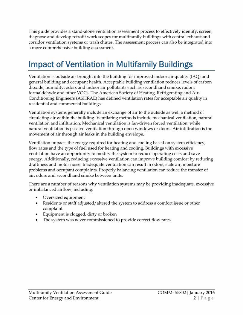
Centralized Apartment Exhaust Ventilation Centralized apartment exhaust ventilation systems have one or multiple fans that continuously exhaust air from apartment unit bathrooms, kitchens, or both kitchens and bathrooms (Figure 1). Each fan pulls exhaust air from a common shaft which is ducted to multiple apartment units through smaller branch ducts. Rooftop fans often serve multiple vertically aligned apartments directly below them. Alternatively, there may be one central fan that has multiple shafts with each shaft branching to draw air from an apartment unit.
Central exhaust systems typically draw air from bathrooms and kitchens – areas with high moisture and/or odor sources. They can also provide general ventilation to the apartment. The exhaust system mechanically draws air from the unit, and replacement air comes into the unit from outside (infiltration) or other parts of the building. A corridor ventilation system may be paired with an exhaust system to provide “make-up air” or supply air to mechanically replace the ventilation air exhausted from apartments.
Reducing excessive exhaust flows and balancing exhaust flow distribution throughout the building will reduce operating costs and improve the ventilation system performance by reducing air, odor and secondhand smoke transfer between units.
Multifamily Ventilation Assessment Guide COMM- 55802| January 2016 Center for Energy and Environment 6 | P a g e
Figure 1. Common centralized apartment exhaust fan configurations
Left: Exhaust fan serving both the kitchen and baths of vertically stacked apartments. Right: Exhaust fan serving back to back bathrooms.
Exhaust Air Inlet Regulating Devices A variety of devices are used to help regulate the amount of exhaust airflow. They are integrated into or just behind the inlet grille and include: fixed orifices, adjustable dampers, fixed or adjustable louvers, and constant air regulators (CARs) (Figure 2). These devices are used to adjust the exhaust flow rate so that proper flows are pulled from each room served by a rooftop fan. Without flow regulating devices, the inlet flows from bottom floor units compared to upper floor units may vary due to stack effect or proximity to the rooftop fan. Some devices are adjustable, while others are fixed. Adjustable devices may either be self-adjusting based on pressure (constant airflow regulators) or require manual adjustment of an adjustable damper or louver.
Dust buildup and clogging is a concern for all flow adjusting devices. CARs appear to be more prone to clogging due to their rubber bladder and irregular shaped hole (Figure 3a). In addition, the older style CARs may not regulate properly when their pressure port is clogged. A newer style of constant air regulator, the CAR II, does not have a rubber bladder but instead uses a plastic airfoil to balance airflow. This design may prove to be less prone to clogging than the original CAR. Balancing louvers are also prone to clogging (Figure 3b). Fixed orifices that have a smooth and regular shape have the least surface area to trap dust and debris (Figure 2d). These are the least likely to clog and are easier to clean.

Multifamily Ventilation Assessment Guide COMM- 55802| January 2016 Center for Energy and Environment 7 | P a g e
Figure 2. Exhaust ventilation flow regulating devices (found behind the inlet register grilles)
Figure 3. Clogged orifices
Figure 2a. Balancing louver integrated with
inlet grille Figure 2b. CAR II automatic balancing orifice
Figure 2c. CAR I automatic balancing orifice Figure 2d. Fixed orifice sized for proper flow
Figure 3a. A very dirty Constant Air Regulating (CAR) automatic balancing orifice
Figure 3b. A dirty balancing louver

Multifamily Ventilation Assessment Guide COMM- 55802| January 2016 Center for Energy and Environment 8 | P a g e
Exhaust Fans There are a variety of centralized exhaust fan types. The most common type is a packaged exhaust fan or packaged roof ventilator (PRV) that is located on the roof. Some are belt driven and others are direct drive. These fans typically serve one or two duct shafts over vertically stacked apartment units. While the cap and shape of the fan and housing can vary in size and shape, they are commonly the mushroom or box shape (Figure 4).
Larger buildings may have a single large centralized exhaust fan that serves a manifold where all exhaust air ducts are routed. This ducted fan is typically located in a penthouse mechanical room where it pushes exhaust air through an outlet grill to the outdoors (Figure 5).
The main performance issue with centralized exhaust fans is improper sizing or speed, which causes the fan(s) to exhaust too much or too little air. Many rooftop ventilator fans do not have speed adjustment to help with this issue. Some can be resheaved to change the size of the belt and sheave (e.g. wheel or roller), decreasing the fan RPMs. However, some fans have a minimum diameter sheave and cannot be adjusted to a speed that is low enough to properly serve the building. When this is the case, replacing the fan with a properly sized electrically commutated motor and integral speed adjustment is needed to save power and allow a full range of fan adjustment.
Figure 4. Roof Exhaust fans
Figure4a. Mushroom shape. Figure 4b. Box shape.

Multifamily Ventilation Assessment Guide COMM- 55802| January 2016 Center for Energy and Environment 9 | P a g e
Figure 5. Large utility fan exhausting all apartments in building
Distribution System The ductwork for a centralized exhaust system typically consists of a main vertical shaft(s) with horizontal branch ducts to the inlet in each unit, typically located in the unit kitchen and/or bathroom. Air travels from the kitchen or bathroom through the inlet register grille before moving through any airflow regulating device and into a branch duct. Branch ducts connect to a main shaft. A fire damper or subduct is used when branch ducts pass from an apartment to another apartment or hallway. These are required by code to form a fire barrier. Multiple branch ducts connect to the shaft and the shaft routes the air to the fan where it is pushed outdoors.
Unsealed, misaligned or disconnected ducts in a central exhaust system can drastically affect exhaust ventilation performance. The most common air leaks occur where the shaft terminates into the base of the fan at the roof and where the duct inlet collects air from the apartment unit. At the rooftop, where the fan sits atop a structural frame called a curb (Figure 6) it is common to find a leaky connection between the exhaust duct and the fan. This can cause exhaust air to be unintentionally drawn from the roof cavity or wall cavities (Figure 7). In the unit there may be a leaky connection from the branch duct to the finished ceiling or wall of the apartment, causing air to be drawn to wall cavities instead of the apartment interior (Figure 8). When modifying an exhaust system, air sealing at these locations is a low cost measure that improves system performance and efficiency. The exhaust system may have other duct leaks that are difficult to access. Evaluating the severity of inaccessible duct leaks is an important diagnostic step. Commonly, air leakage exists where the duct penetrates the floor of each level of the building. Exhaust shafts may be constructed of gypsum board and may not be taped in all locations to have an effective seal. Other systems may have metal ductwork, but contain disconnected or misaligned sections of the duct. If the leakage gaps are large, it could affect overall ventilation distribution and should be accessed and fixed before reducing flows to save energy. Small duct leaks, gaps 1/2” or smaller, can be sealed with an airborne aerosol sealant such as Aeroseal (Aeroseal.com).
Figure 5a. Fan in penthouse. Figure 5b. Exhaust grille on penthouse wall.
Multifamily Ventilation Assessment Guide COMM- 55802| January 2016 Center for Energy and Environment 10 | P a g e
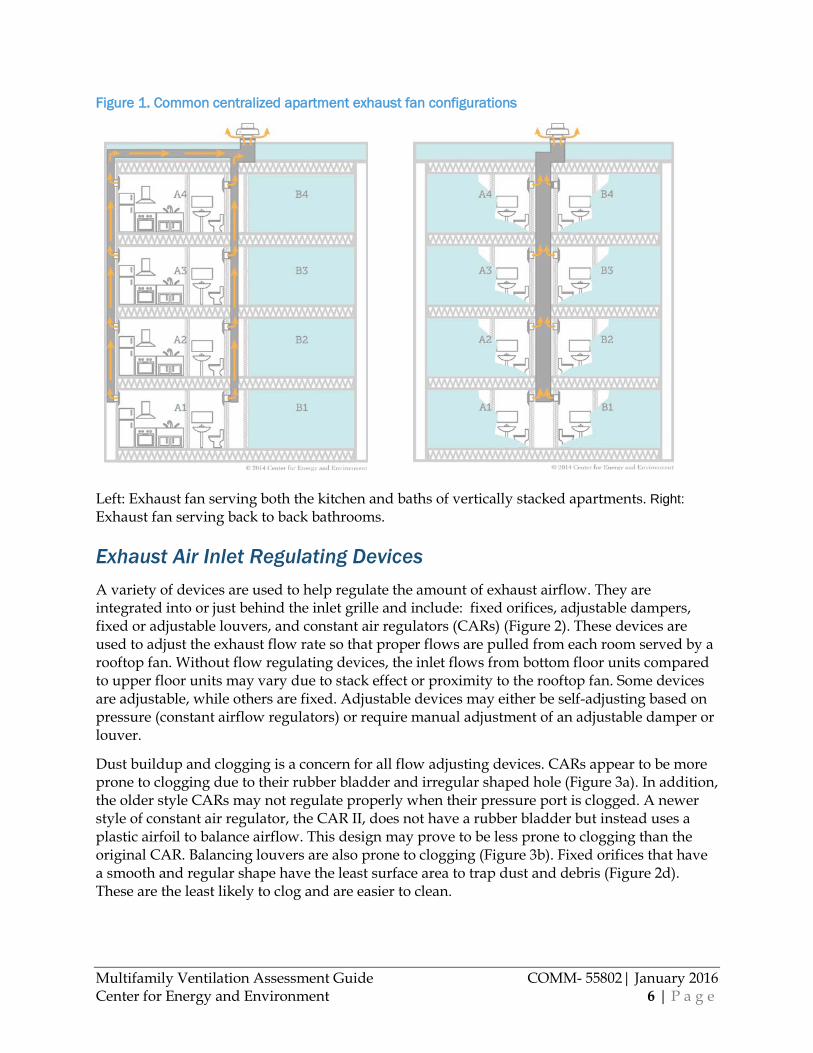
Figure 6. Exposed roof curb
Figure 7. Duct leakage at roof curb below PRV fan
Figure 7 is a picture is looking down a ventilation shaft from the roof after removing the PRV exhaust fan. There is a gap between the gypsum shaft and roof curb under the fan that is allowing air to be exhausted from the roof cavity and other unintended places.

Multifamily Ventilation Assessment Guide COMM- 55802| January 2016 Center for Energy and Environment 11 | P a g e
Figure 8. Duct leakage around exhaust inlet
Figure 8 is a picture of a bathroom exhaust duct with a CAR orifice. The connection to the ceiling drywall has a 1/2" gap around most of its perimeter, causing air to be drawn from unintended wall and ceiling cavities.
System Components Powered Roof Ventilator (PRV) or roof exhaust fan. A packaged fan that continuously draws air out of the building for the purposes of exhaust ventilation (Figures 4a and 4b). It is connected to multiple apartment units via a system of ductwork. There are typically multiple fans serving one building.
Roof curb. A roof support structure and frame around a ventilating fan or other flat roof penetration. The curb is integrated into the roofing drainage plane, the roof membrane, and is intended as a mounting platform and housing for the ducted connection to the ventilating fan. Figure 6 shows photos of an exposed roof curb.
Main duct, ventilation shaft, or exhaust riser. The main duct with multiple branch ducts from apartment units that join to flow towards the roof exhaust fan.
Branch ducts. Narrower ducts that take off from the main duct to collect air from a specific room in an apartment.
Subducts or fire dampers. Two methods of isolating smoke and flames in ductwork that are located at the fire barrier of a partition wall. Code typically allows either one or the other to be used.
Exhaust grille/register. A louvered inlet for the exhaust duct that is found in the bathroom or kitchen.
Balancing louvers. Adjustable louvers that are used to balance and tune airflows. These are either located behind the exhaust grille or are integrated with the grille.
Constant Airflow Regulator. An adjustable inflatable bulb orifice restrictor or airfoil often located behind the exhaust grille for self-balancing and tuning air flows.
Fixed balancing orifice. A specifically sized round or square orifice restrictor located behind the exhaust grille to balance airflows.
Multifamily Ventilation Assessment Guide COMM- 55802| January 2016 Center for Energy and Environment 12 | P a g e
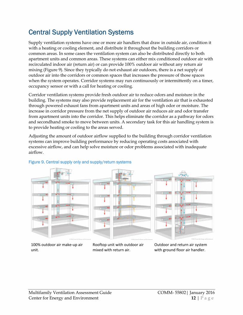
Central Supply Ventilation Systems Supply ventilation systems have one or more air handlers that draw in outside air, condition it with a heating or cooling element, and distribute it throughout the building corridors or common areas. In some cases the ventilation system can also be distributed directly to both apartment units and common areas. These systems can either mix conditioned outdoor air with recirculated indoor air (return air) or can provide 100% outdoor air without any return air mixing (Figure 9). Since they typically do not exhaust air outdoors, there is a net supply of outdoor air into the corridors or common spaces that increases the pressure of those spaces when the system operates. Corridor systems may run continuously or intermittently on a timer, occupancy sensor or with a call for heating or cooling.
Corridor ventilation systems provide fresh outdoor air to reduce odors and moisture in the building. The systems may also provide replacement air for the ventilation air that is exhausted through powered exhaust fans from apartment units and areas of high odor or moisture. The increase in corridor pressure from the net supply of outdoor air reduces air and odor transfer from apartment units into the corridor. This helps eliminate the corridor as a pathway for odors and secondhand smoke to move between units. A secondary task for this air handling system is to provide heating or cooling to the areas served.
Adjusting the amount of outdoor airflow supplied to the building through corridor ventilation systems can improve building performance by reducing operating costs associated with excessive airflow, and can help solve moisture or odor problems associated with inadequate airflow.
Figure 9. Central supply only and supply/return systems
100% outdoor air make-up air unit.
Rooftop unit with outdoor air mixed with return air.
Outdoor and return air system with ground floor air handler.

Multifamily Ventilation Assessment Guide COMM- 55802| January 2016 Center for Energy and Environment 13 | P a g e
Airhandlers
Figure 10. Types of air handlers
The air handling unit regulates and circulates airflow. There are a variety of types of air handlers (Figure 10), which are often referred to as make-up air units (MUA). The air handling unit typically contains an outdoor air intake, air filters, air mixing dampers, and fan, as well as heating and cooling elements. However, simpler air handlers can contain only an outdoor air intake, filters, outdoor air damper and a fan. The air handling unit is connected to a system of ducts that distributes air throughout the building corridors. Some air handlers supply and condition 100% of outside air with no recirculated air and other air handling systems can incorporate return or recirculated air. If the unit is designed to recirculate air it will be connected to a return plenum or duct, in addition to a supply plenum and outdoor air intake. This type of unit can provide a variable volume of outdoor air that is mixed with return or recirculated air. The outdoor air volume is controlled by either a motorized or manual damper. Air handlers could be located indoors or outdoors. If indoors, air handlers are ducted to a large air intake grille either on the building or penthouse wall or the roof. The rooftop units (RTUs)
Rooftop unit. Make up air unit.
In-line fan.

Multifamily Ventilation Assessment Guide COMM- 55802| January 2016 Center for Energy and Environment 14 | P a g e
are packaged units designed for outdoor use and can provide either 100% of outdoor air or a mix of outdoor and recirculated air with a motorized damper. In addition to varying the amount of outdoor air volume, air handlers can be equipped with variable speed fan motors and modulating heating elements to allow for a large range of adjustments that can be made from a control panel on or near the unit or, in some cases, remotely with a building automation system.
Assessment of central supply ventilation systems is essentially the measuring of the quantity of outdoor air that is pulled in through the outdoor air intake. If the outdoor air supplied to the building is found to be too high or low, it is necessary to troubleshoot the system before making any flow adjustments. Common issues with these systems include:
• A broken or malfunctioning damper actuator or damper control arm/linkage, allowing too much or too little outdoor air into the building (Figure 11a)
• Dust and debris clogged filters, bird screens and heating or cooling coils (Figure 11b) • Plenum access door(s) that do not close properly, allowing an air bypass to impact
overall system performance • Erratic system function caused by control failure or sensor failure
Figure 11. Examples of air handler issues
The method of adjusting or balancing the air handler outdoor air flow rate depends on the type and capability of the air handler. Make up air unit adjustment involves resizing sheaves for a single speed fan, or turning down a variable frequency drive control or adjustable speed fan. If the air handler recirculates indoor air to mix with outdoor air though a return duct, the outdoor air flow rate is varied by adjusting the open position of the outdoor air damper. Any of these adjustments are routine for a qualified test and balance (TAB) contractor.
Distribution System Corridor ventilation air handlers distribute ventilation air though a system of ducts. The system may incorporate both supply and return ducts or only supply ducts. Ducts terminate to a register where the air flows into the intended corridor or common area.
Figure 11a. Air damper actuator failed in open position
Figure 11b. Close-up view of clogged air intake bird screen

Multifamily Ventilation Assessment Guide COMM- 55802| January 2016 Center for Energy and Environment 15 | P a g e
The size, shape and location of the air distribution registers, as well as the distance air travels to registers, will affect ventilation performance. However, these cannot be cost-effectively adjusted or repaired. These design issues should be noted during a building assessment to guide your discussion with the building management. Common distribution design issues include:
• Short-circuited airflow, caused by supply and return registers that are located too close together
• Inadequate register grille area for intended airflows, meaning supply or return registers are sized too large or too small to effectively accommodate the desired flow rate
Sealing ducts and/or balancing air flow rates can often address performance issues. Of these two, balancing flow is often the most cost effective for addressing inadequate corridor flows and should be the first step when troubleshooting distribution issues.
System Components Rooftop Unit (RTU). The air handler on a rooftop that provides conditioned outdoor air to ventilate and heat and cool building air.
Make-up air. The replacement air that is supplied by an air handler for the purposes of replacing air that is exhausted by the centralized exhaust system.
Balancing dampers. Motor actuated or manually adjusted dampers that restrict airflow.
Economizer. Motor actuated damper that allows variable amounts of outdoor air to be drawn into the building. Sensors control louvers to open to provide up to 100% outdoor air and disable compressor cooling when there is a call for cooling and the outdoor air is cooler than indoor air.
Supply registers. The grille emitting conditioned forced air supply via ducts to an area of the building.
Return registers. The grille allowing return of air to the air handler for conditioning and distribution.
Fire or smoke dampers. A heat or smoke actuated damper used for isolation of smoke and flames in ductwork and located at the fire barrier of a partition wall.
Damper actuator. The term for the triggering force for damper position change. This is either motor driven and controlled electronically or pneumatically by a temperature or occupancy sensor.
Wire mesh bird screen. Wire mesh over an outdoor air intake that prevents birds and other animals from entering the building.
Air filter. A rack and filtration medium, commonly fiberglass, that removes large dust and floating debris from the air stream.
Sheave. A wheel on a motor or fan with a groove holding a belt.

Multifamily Ventilation Assessment Guide COMM- 55802| January 2016 Center for Energy and Environment 16 | P a g e
Figure 12. Register grilles
Left: ceiling supply diffuser, Right: return register.
Trash Chutes A trash chute is a large shaft that runs vertically through the building with doors on each floor to provide occupant access for trash disposal (Figure 13). The chute is typically about 2’ in diameter, terminates into a dumpster or compactor on the ground level, and extends to the rooftop with a hooded termination to provide natural exhaust ventilation via stack effect. There is usually continuous exhaust ventilation in the trash rooms and/or dumpster or compactor room that is provided by either a rooftop exhaust fan or a motorized fan unit in the room.
Figure 13. Typical trash chute configuration

Multifamily Ventilation Assessment Guide COMM- 55802| January 2016 Center for Energy and Environment 17 | P a g e
A functioning trash chute exhaust system is important to overall building energy performance and indoor air quality. Chronic trash odors may cause some building operators to run other ventilation systems at higher rates to dilute or exhaust odors, increasing building operating costs. Adjustments made to central ventilation systems may also have adverse effects on a trash chute system if the trash chute is not properly isolated from building pressures and airflows. For this reason, understanding and evaluating trash chutes for effective performance is important for a comprehensive building ventilation assessment.
Rooftop Termination The trash chute terminates at the rooftop to allow trash odors to travel to the building exterior via the thermal stack effect. During colder weather the more dense outdoor air causes air to be drawn in at the bottom of the building and less dense inside air to be forced out at the top. This effect also causes air to be drawn into the trash chute from the building interior and out the roof termination. Depending on the type and location of the termination, wind blowing over the top of the building can cause more air to be drawn out of the trash chute. This occurs without fan assistance. The size of the opening at the rooftop termination directly affects the amount of air that can flow out of the chute. For example, large chute openings can draw an excessive amount of conditioned air from the building, affecting the energy performance of the building. Small or blocked openings may not draw enough air from the building, causing trash odors to permeate the building. Figure 14 shows trash chute caps with a large versus small opening. Adjusting the open area at the rooftop termination to reduce excessive chute exhaust flow is a low-cost energy saving technique.
Figure 14. Trash chute rooftop terminations
Left: Typical roof termination opening, Right: Large termination opening. Thermal stack effect is drawing trash up the chute.
Dumpster or Compactor Room Building trash deposited into the trash chute falls into a dumpster or a compactor on the bottom floor of the building. The point where the trash exits the chute and enters the compactor or

Multifamily Ventilation Assessment Guide COMM- 55802| January 2016 Center for Energy and Environment 18 | P a g e
dumpster is referred to as the chute outlet (Figure 15). The air leakage characteristics of the room enclosure around the chute outlet can affect the amount of air escaping the building through the chute from both the stack effect and wind. The room with the chute outlet should be isolated from the rest of the conditioned building. Ideally, the dumpster and chute outlet have a dedicated room with a door directly to the exterior of the building. Any air leaks connecting building air with this room (such as an unweatherstripped door, unsealed ducts or pipe penetrations) increase the likelihood of trash odors escaping into the building with fluctuating building pressure changes. In many buildings dumpster room doors are propped open for ease of access, allowing a large connection between the dumpster room and building air. In some instances the dumpster room is also a mechanical or storage room, making it difficult to isolate from building air. Dumpster rooms that are not isolated from building air can cause odor problems and excessive chute exhaust flows, depending on the weather. If the dumpster room is difficult to isolate, chute outlets can be sealed to the top of trash compactors with sheet metal plenums to separate chute air from the building air.
All trash rooms should have continuous exhaust ventilation at a code-specified rate. The required exhaust flow rate from the trash room depends on the room floor area (1 cfm/ft² of room area). It is best if the exhaust flow creates a negative pressure in the room relative to the adjoining building area so that any air leaks draw building air into the room and do not allow trash room air to escape into the rest of the building. During an assessment, both verification of the exhaust flow rate and a visual inspection of the air seal of the dumpster room are important steps.
Figure 15. Trash chute outlets in the dumpster and compactor rooms
Open chute Chute sealed to the compactor with sheet metal

Multifamily Ventilation Assessment Guide COMM- 55802| January 2016 Center for Energy and Environment 19 | P a g e
Trash Disposal Rooms Similar to the dumpster room, the trash chute disposal rooms (Figure 16) on each floor should be isolated from the building conditioned air and ventilated with mechanical exhaust ventilation at a code-specified rate. Any penetration into this room can result in odor transfer. The trash chute assessment should include an inspection of these rooms to determine whether trash room doors are kept closed, penetrations to the rooms are sealed, and continuous ventilation is exhausted from the room at the code-specified rate.
Figure 16. Trash disposal access from hallway
System Components Dumpster/compactor/trash room. The room where the trash chute empties in to a dumpster or compactor. It should be isolated from building conditioned air to prevent odor problems or energy waste.
Chute outlet. The bottom of the trash chute that empties into a dumpster or compactor. It should be sealed to the top of the compactor or enclosed in a small airtight room. Limiting airflow to the chute improves its overall performance.
Trash disposal access doors. Access doors that open into the trash chute for trash deposits from apartment residents. These are typically located in a small trash disposal room in the hallway on every floor of the building with a fire door separating the hallway from the shaft for fire and ventilation code compliance.
Rooftop exhaust termination. The housing and hood over the top of the trash chute meant to prevent rain or other precipitation from falling into the shaft and to limit the exhaust airflow out of the stack.

Multifamily Ventilation Assessment Guide COMM- 55802| January 2016 Center for Energy and Environment 20 | P a g e
Airflow Measurement Methods There are several methods that can be used to obtain useful airflow measurements. Some methods may offer better accuracy, but require more time and equipment. Other methods may result in lower accuracy, but require less time, expertise and equipment. Certain methods may be better suited for specific buildings or situations. Some measurement methods may require specific access to ducts or equipment locations that are difficult or impossible to access in some buildings. Additionally, working on the rooftop of a high-rise building can be a rugged experience and wind speeds, snow, ice, rain and sun may dictate which testing methods are safe and sensible. Familiarity with a variety of measurement techniques will allow for greater flexibility and efficiency.
In many cases, using a simpler initial test method allows auditors to efficiently screen buildings for ventilation deficiencies at lower labor and equipment cost. If over or under-ventilating conditions are identified, a second diagnostic test can be performed with more accurate airflow measurement techniques. This section identifies low-cost, quick measurement methods that can be used for initial investigations to offer enough accuracy to draw basic conclusions, as well as higher accuracy methods that can be used for further investigation when a second diagnostic visit is deemed necessary.
Table 2. Recommended airflow measurement methods
Measurement Type Purpose
Building Screening Diagnostics
Apartment or trash room exhaust grille Exhaust Fan Flow Meter Box FlowBlaster or Exhaust Fan
Flow Meter Box
Rooftop exhaust fan serving apartments or trash rooms TrueFlow capture box
(1) TrueFlow capture box (2) TrueFlow meter below fan (3) DuctBlaster capture box
Rooftop or makeup unit outdoor air intake
(1)Vane or hot wire anemometer duct traverse (2)Vane traverse at all supply register grilles*
(1) Hot wire anemometer or pitot tube duct traverse (2) Customized TrueFlow Meter frame (3) Temperature method
*For 100% outdoor air ventilation systems only—not suitable for systems with recirculated/return air mixed with outdoor air.
Apartment Exhaust Inlet Grille Measurement Inlet grille measurements are used to confirm that apartment centralized exhaust systems have the required flow rate for a specific area, typically the bathroom or kitchen. An Exhaust Fan Flow Meter (from The Energy Conservatory) and micromanometer (available from The Energy

Multifamily Ventilation Assessment Guide COMM- 55802| January 2016 Center for Energy and Environment 21 | P a g e
Conservatory, DG700) can be used for screening visit airflow measurements and are sufficient for most diagnostic measurements. A fan-powered box or hood (The FlowBlaster™ Capture Hood Accessory for the Duct Blaster®, available from The Energy Conservatory,) compensates for the box or hood restriction and provides more accurate measurements for flow rates greater than 20 cfm. In most cases the 10% accuracy of the Flow Meter is sufficient for screening measurements and the improved 5% accuracy of the FlowBlaster is not needed for most diagnostic measurements. Both devices require customized capture boxes or attachments for some inlet grilles or kitchen hoods.
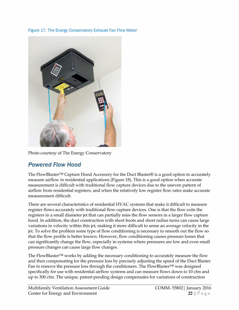
Exhaust Fan Flow Meter The Exhaust Fan Flow Meter (Figure 17) is designed to make quick and accurate measurements of airflow through residential exhaust fans. The effective airflow measurement range for the Exhaust Fan Flow Meter is 10 to 124 cubic feet per minute (cfm). The device should be used along with a pressure gauge providing 0.1 Pascals (0.0004 in. w.c.) resolution in the range of 1 to 8 Pascals. When used with The Energy Conservatory’s DG-700 digital pressure gauges, the accuracy of the exhaust fan flow measurement is +/- 10%. The flow restriction of the device will result in a slightly lower measurement. However, this reduction will typically be less than 5% when the shaft pressure is greater than 40Pa and less than 10% when the shaft pressure is greater than 20Pa1.
During the measurement procedure, the Exhaust Fan Flow Meter is placed directly over the exhaust fan grille and is pushed up against the wall or ceiling so that the flexible gasket on the end of the Metering Box creates an airtight seal around the grille. The pressure reading taken from the Exhaust Fan Flow Meter can be easily converted to airflow in cfm using a flow table that comes with the Metering Box. The DG-700 or DG-3 digital pressure gauge can also be set up to display airflow readings directly in cfm. The Exhaust Fan Flow Meter has three calibrated openings to provide an accurate measurement over the full range of the device. It also contains a short handle that can be attached to the Metering Box using Velcro strips. The handle is designed to allow a standard painter’s pole or broom handle (not included) to be screwed into the open end of the handle to provide access to exhaust fan grilles mounted high on walls or ceilings.2
A complete Manual for the Exhaust Fan Flow Meter is available at: http://energyconservatory.com/wp-content/uploads/2014/07/Flow-Box-Manual-DG-700.pdf
1 The measurement will be reduced by less than 5% when the Flow Meter pressure is less than 10% of the shaft pressure. 2 Information in this section was taken with permission from The Energy Conservatory.
Multifamily Ventilation Assessment Guide COMM- 55802| January 2016 Center for Energy and Environment 22 | P a g e
Figure 17. The Energy Conservatory Exhaust Fan Flow Meter
Photo courtesy of The Energy Conservatory
Powered Flow Hood The FlowBlaster™ Capture Hood Accessory for the Duct Blaster® is a good option to accurately measure airflow in residential applications (Figure 18). This is a good option when accurate measurement is difficult with traditional flow capture devices due to the uneven pattern of airflow from residential registers, and when the relatively low register flow rates make accurate measurement difficult.
There are several characteristics of residential HVAC systems that make it difficult to measure register flows accurately with traditional flow capture devices. One is that the flow exits the registers in a small diameter jet that can partially miss the flow sensors in a larger flow capture hood. In addition, the duct construction with short boots and short radius turns can cause large variations in velocity within this jet, making it more difficult to sense an average velocity in the jet. To solve the problem some type of flow conditioning is necessary to smooth out the flow so that the flow profile is better known. However, flow conditioning causes pressure losses that can significantly change the flow, especially in systems where pressures are low and even small pressure changes can cause large flow changes.
The FlowBlaster™ works by adding the necessary conditioning to accurately measure the flow and then compensating for the pressure loss by precisely adjusting the speed of the Duct Blaster Fan to remove the pressure loss through the conditioners. The FlowBlaster™ was designed specifically for use with residential airflow systems and can measure flows down to 10 cfm and up to 300 cfm. The unique, patent-pending design compensates for variations of construction

Multifamily Ventilation Assessment Guide COMM- 55802| January 2016 Center for Energy and Environment 23 | P a g e
and is able to measure the flow more accurately than commercial capture hood devices used in the residential market. The flow accuracy is the greater of +/- 5% of flow or +/- 2cfm.3
A complete manual for the FlowBlaster™ is available at: http://energyconservatory.com/wp-content/uploads/2014/07/FlowBlaster-Manual.pdf
Figure 18. FlowBlaster powered flow hood
Photo courtesy of The Energy Conservatory
Central Exhaust Fan Outlet Measurement Central exhaust fan outlet measurements are used to help determine the total amount of air drawn through the exhaust inlet grilles for the apartment units it serves. Comparing the measured flow rate to the desired flow rate can indicate whether the fan is providing too much or too little exhaust flow. Comparing the total flow rate at the exhaust fan with the total measured flow of all the exhaust inlets it serves indicates the amount of exhaust that is pulled successfully from the inlet grilles in the apartments versus from duct leaks elsewhere in the building.
For building screening or diagnostics, using a customized capture box with the TrueFlow Meter (available from The Energy Conservatory) fitted to the top of the box is the quickest way to measure the flow rates. Alternatively, a capture box or central exhaust grille fitted with a calibrated fan or the TrueFlow Meter fitted in the duct right below the rooftop exhaust outlet could be more sensible choices for diagnostic measurements in certain conditions. All methods
3 Information in this section was taken with permission from The Energy Conservatory.
Multifamily Ventilation Assessment Guide COMM- 55802| January 2016 Center for Energy and Environment 24 | P a g e
require some equipment customization to accommodate various fan sizes and shapes. This section describes each method of exhaust flow measurement and when to use it.
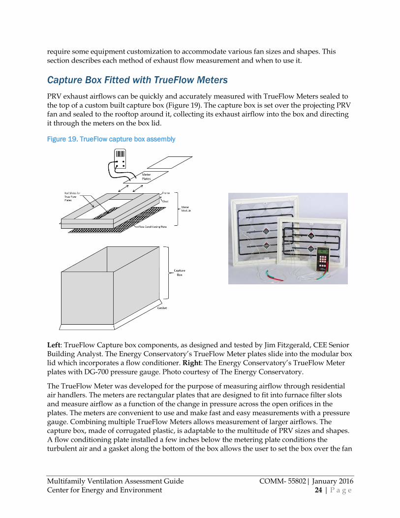
Capture Box Fitted with TrueFlow Meters PRV exhaust airflows can be quickly and accurately measured with TrueFlow Meters sealed to the top of a custom built capture box (Figure 19). The capture box is set over the projecting PRV fan and sealed to the rooftop around it, collecting its exhaust airflow into the box and directing it through the meters on the box lid.
Figure 19. TrueFlow capture box assembly
Left: TrueFlow Capture box components, as designed and tested by Jim Fitzgerald, CEE Senior Building Analyst. The Energy Conservatory’s TrueFlow Meter plates slide into the modular box lid which incorporates a flow conditioner. Right: The Energy Conservatory’s TrueFlow Meter plates with DG-700 pressure gauge. Photo courtesy of The Energy Conservatory.
The TrueFlow Meter was developed for the purpose of measuring airflow through residential air handlers. The meters are rectangular plates that are designed to fit into furnace filter slots and measure airflow as a function of the change in pressure across the open orifices in the plates. The meters are convenient to use and make fast and easy measurements with a pressure gauge. Combining multiple TrueFlow Meters allows measurement of larger airflows. The capture box, made of corrugated plastic, is adaptable to the multitude of PRV sizes and shapes. A flow conditioning plate installed a few inches below the metering plate conditions the turbulent air and a gasket along the bottom of the box allows the user to set the box over the fan
Multifamily Ventilation Assessment Guide COMM- 55802| January 2016 Center for Energy and Environment 25 | P a g e
achieving a seal without tape. Once in place, the capture box can make a reading in three minutes or less.
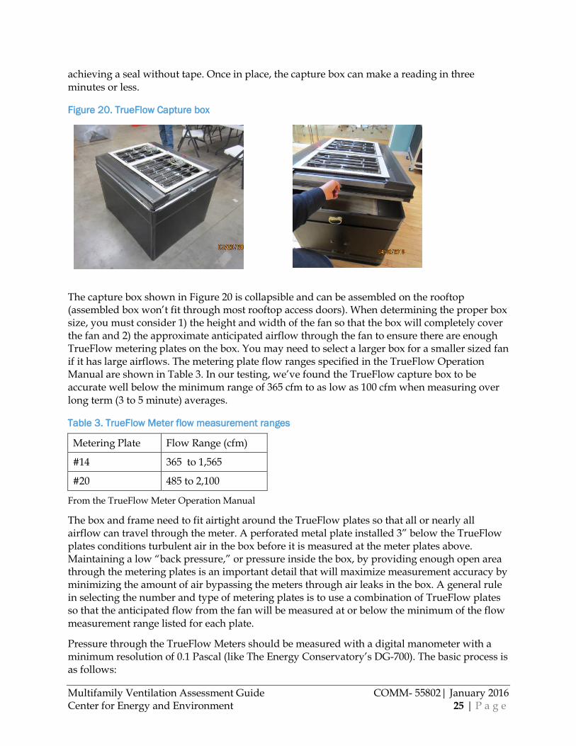
Figure 20. TrueFlow Capture box
The capture box shown in Figure 20 is collapsible and can be assembled on the rooftop (assembled box won’t fit through most rooftop access doors). When determining the proper box size, you must consider 1) the height and width of the fan so that the box will completely cover the fan and 2) the approximate anticipated airflow through the fan to ensure there are enough TrueFlow metering plates on the box. You may need to select a larger box for a smaller sized fan if it has large airflows. The metering plate flow ranges specified in the TrueFlow Operation Manual are shown in Table 3. In our testing, we’ve found the TrueFlow capture box to be accurate well below the minimum range of 365 cfm to as low as 100 cfm when measuring over long term (3 to 5 minute) averages.
Table 3. TrueFlow Meter flow measurement ranges
Metering Plate Flow Range (cfm)
#14 365 to 1,565
#20 485 to 2,100
From the TrueFlow Meter Operation Manual
The box and frame need to fit airtight around the TrueFlow plates so that all or nearly all airflow can travel through the meter. A perforated metal plate installed 3” below the TrueFlow plates conditions turbulent air in the box before it is measured at the meter plates above. Maintaining a low “back pressure,” or pressure inside the box, by providing enough open area through the metering plates is an important detail that will maximize measurement accuracy by minimizing the amount of air bypassing the meters through air leaks in the box. A general rule in selecting the number and type of metering plates is to use a combination of TrueFlow plates so that the anticipated flow from the fan will be measured at or below the minimum of the flow measurement range listed for each plate.
Pressure through the TrueFlow Meters should be measured with a digital manometer with a minimum resolution of 0.1 Pascal (like The Energy Conservatory’s DG-700). The basic process is as follows:

Multifamily Ventilation Assessment Guide COMM- 55802| January 2016 Center for Energy and Environment 26 | P a g e
Measure the airflow rate using the following step by step process:
1. Measure normal system operating pressure (NSOP). Before the capture box is put in place, measure the NSOP in the duct. Drill a hole and insert a pressure probe in the fan base housing and into the ventilation shaft below the fan. For windy conditions, the stability of the operating pressure can be improved by using the building interior as the reference pressure. Record the average pressure over 1 to 5 minutes, depending on wind speed. Reference Table 4 to determine the duration of measurement averages for the NSOP. Keep the probe in place for step three (3).
Table 4. Duration of pressure averaging measurement
Wind (mph) # Minutes
Calm (0-5) one
Light (6-10) two
Moderate (11-15) three
Strong (15+) five
2. Install capture box. Place the capture box over the fan and ensure it is sealed effectively to the roof.
3. Measure TrueFlow system operating pressure (TFSOP) and plate flow rate. The TFSOP reference pressure location (inside or outside) should be consistent with the NSOP location. Record 1 to 5 minute averages of the TFSOP, depending on wind speed (see Table 4). Similarly record 1 to 5 minute average values for each metering plate. If your gauge reads flow directly, record the flow rate. If you recorded the plate pressure(s), use the equations below to compute flow rates from the meter plate pressure(s):
𝑴𝑴𝑴𝑴𝑴𝑴𝑴𝑴𝑴𝑴𝑴𝑴𝑴𝑴𝑴𝑴 𝒑𝒑𝒑𝒑𝒑𝒑𝑴𝑴𝑴𝑴 #𝟏𝟏𝟏𝟏:𝑭𝑭𝒑𝒑𝑭𝑭𝑭𝑭 (𝒄𝒄𝒄𝒄𝒄𝒄) = 𝟏𝟏𝟏𝟏𝟏𝟏 × (𝑻𝑻𝑴𝑴𝑻𝑻𝑴𝑴𝑭𝑭𝒑𝒑𝑭𝑭𝑭𝑭 𝑷𝑷𝒑𝒑𝒑𝒑𝑴𝑴𝑴𝑴 𝑷𝑷𝑴𝑴𝑴𝑴𝑷𝑷𝑷𝑷𝑻𝑻𝑴𝑴𝑴𝑴,𝑷𝑷𝒑𝒑)𝟎𝟎.𝟏𝟏
𝑴𝑴𝑴𝑴𝑴𝑴𝑴𝑴𝑴𝑴𝑴𝑴𝑴𝑴𝑴𝑴 𝒑𝒑𝒑𝒑𝒑𝒑𝑴𝑴𝑴𝑴 #𝟐𝟐𝟎𝟎:𝑭𝑭𝒑𝒑𝑭𝑭𝑭𝑭 (𝒄𝒄𝒄𝒄𝒄𝒄) = 𝟏𝟏𝟏𝟏𝟏𝟏 × (𝑻𝑻𝑴𝑴𝑻𝑻𝑴𝑴𝑭𝑭𝒑𝒑𝑭𝑭𝑭𝑭 𝑷𝑷𝒑𝒑𝒑𝒑𝑴𝑴𝑴𝑴 𝑷𝑷𝑴𝑴𝑴𝑴𝑷𝑷𝑷𝑷𝑻𝑻𝑴𝑴𝑴𝑴,𝑷𝑷𝒑𝒑)𝟎𝟎.𝟏𝟏
4. Return to normal operating conditions. Remove the capture box and seal the pressure probe hole.
5. Calculate the Flow Resistance Correction Factor. The Flow Resistance Correction Factor is used to compensate for the reduction in air flow caused by the capture box and metering plates. Use the NSOP and TFSOP to calculate the Flow Resistance Correction Factor based on the equation below from the TrueFlow Operation Manual:
𝑭𝑭𝒑𝒑𝑭𝑭𝑭𝑭 𝑹𝑹𝑴𝑴𝑷𝑷𝑴𝑴𝑷𝑷𝑴𝑴𝒑𝒑𝑴𝑴𝒄𝒄𝑴𝑴 𝑪𝑪𝑭𝑭𝑴𝑴𝑴𝑴𝑴𝑴𝒄𝒄𝑴𝑴𝑴𝑴𝑭𝑭𝑴𝑴 𝑭𝑭𝒑𝒑𝒄𝒄𝑴𝑴𝑭𝑭𝑴𝑴 = �(𝑵𝑵𝑵𝑵𝑵𝑵𝑷𝑷/𝑻𝑻𝑭𝑭𝑵𝑵𝑵𝑵𝑷𝑷)

Multifamily Ventilation Assessment Guide COMM- 55802| January 2016 Center for Energy and Environment 27 | P a g e
6. Compute Corrected Flow Rate. Sum the measured flow from each TrueFlow metering plate and multiply by the Flow Resistance Correction Factor to determine the corrected airflow rate:
𝑻𝑻𝑭𝑭𝑴𝑴𝒑𝒑𝒑𝒑 𝑴𝑴𝒆𝒆𝒆𝒆𝒑𝒑𝑻𝑻𝑷𝑷𝑴𝑴 𝒄𝒄𝒑𝒑𝑭𝑭𝑭𝑭 (𝒄𝒄𝒄𝒄𝒄𝒄)= 𝑵𝑵𝑻𝑻𝒄𝒄 𝑭𝑭𝒄𝒄 𝒑𝒑𝒑𝒑𝒑𝒑 𝑻𝑻𝑴𝑴𝑻𝑻𝑴𝑴𝑭𝑭𝒑𝒑𝑭𝑭𝑭𝑭 𝒑𝒑𝒑𝒑𝒑𝒑𝑴𝑴𝑴𝑴 𝒄𝒄𝒑𝒑𝑭𝑭𝑭𝑭𝑷𝑷 (𝒄𝒄𝒄𝒄𝒄𝒄) × 𝑭𝑭𝒑𝒑𝑭𝑭𝑭𝑭 𝑹𝑹𝑴𝑴𝑷𝑷𝑴𝑴𝑷𝑷𝑴𝑴𝒑𝒑𝑴𝑴𝒄𝒄𝑴𝑴 𝑪𝑪𝑭𝑭𝑴𝑴𝑴𝑴𝑴𝑴𝒄𝒄𝑴𝑴𝑴𝑴𝑭𝑭𝑴𝑴 𝑭𝑭𝒑𝒑𝒄𝒄𝑴𝑴𝑭𝑭𝑴𝑴
This method requires the least equipment cost and labor time and is accurate enough for both building screening and diagnostic measurements. Though this application for TrueFlow meters is not listed in the manufacturer’s instructions, our tests have found it to be accurate within +/-10% if the capture box meets a few basic design parameters:
• A flow conditioning “perforated plate” or screen is installed 3-4 inches below the TrueFlow meters
• Flow conditioner must have at least as much open area as the TrueFlow plates on the capture box
• Provide enough TrueFlow meters so that airflow is not significantly restricted, causing box pressure
• Scale up the number of TrueFlow plates to remain at the bottom of the TrueFlow plate measurement range
• The capture box is airtight and seals effectively around the fan • All or nearly all airflow is captured with the box and directed through the flow
conditioner and then the metering plate for measurement • In windy conditions, longer term pressure averages are measured (5 minutes)
A complete TrueFlow meter operation manual (does not include capture box detail) is available at: http://energyconservatory.com/wp-content/uploads/2014/07/TrueFlow-Manual-DG700.pdf
Specifications for Jim Fitzgerald’s box design and more detailed instructions are available upon request. Contact Jim Fitzgerald, Senior Building Analyst at CEE. Email: [email protected], Phone: 612-244-2416.
Calibrated Fan with Pressure Matching Measuring PRV exhaust airflows with a calibrated fan requires fitting the fan(s) to either 1) a custom capture box that can sit over the top of an exhaust PRV on the roof (Figure 21) or 2) a support frame sealed over an exhaust grille. The first option requires constructing an airtight capture box that will fit completely over the PRV fan and seal to a flat rooftop (similar in construction to the capture box part of the TrueFlow box diagram in Figure 19). The lid of the box is fitted with 1-3 Duct Blaster fans, depending on anticipated PRV fan flow. Each Duct Blaster fan can measure up to 800 cfm in the depressurization configuration needed for the Duct Blasters to draw air from the capture box (this depressurization configuration requires ring one with flow conditioner according to the Duct Blaster manual). Before placing the box over the PRV fan, normal system operating duct pressure is measured with a digital pressure gauge (like The Energy Conservatory’s DG-700). To take this measurement, drill a hole for a pressure probe in the fan base housing and insert the probe into the ventilation shaft below the fan(hole must be resealed after measurement). Leave the pressure probe where it is and then place the box over the fan and adjust the Duct Blasters so that the pressure at the probe matches the normal system operating pressure originally measured. A flow reading with the pressure/flow gauge

Multifamily Ventilation Assessment Guide COMM- 55802| January 2016 Center for Energy and Environment 28 | P a g e
connected to the calibrated fan is taken at this matched pressure. In windy conditions, it may be better to reference the building interior pressure instead of outdoor pressure for the shaft pressure measurements.
If the central exhaust system terminates via a vertical exhaust grille, you can adapt a blower door fan over the grille opening to measure airflow. After measuring normal system operating pressure in the shaft, the exhaust fan should be turned off. The blower door fan(s), installed in the blower door frame and canvas, should be masked to the grille opening. Mask off the open area, directing all airflow through the fan(s). Once the exhaust fan power is resumed, adjust the blower door fan is adjusted to match the normal system operating duct pressure at the same location as was originally measured. Take a flow reading with the pressure gauge at this matched pressure.
Though pressure matching with fans is significantly more time consuming and equipment intensive than measuring with a TrueFlow capture box, it can be useful in situations where it is difficult to get an airtight seal where the capture box meets the rooftop, for example when with a rough surface over the roof membrane. Because there is very little or no pressure difference between the capture box and surrounding area, small breeches in the airtightness of the capture box are less likely to affect the flow measurement accuracy.
More detailed instructions on the “pressure matching” method with Duct Blasters are available at: http://energyconservatory.com/wp-content/uploads/2014/07/Duct-Blaster-Manual-Series-B-DG700.pdf (see chapter 13.1 Measuring Total System Airflow. Pg. 54—instructions are intended for measuring airflow through an air handler, but same basic process is used for PRV measurement through a capture box or over a large exhaust grille).
Figure 21. Customized capture box with 3 Duct Blaster fans: PRV flow is measured by matching normal operating duct pressure
Multifamily Ventilation Assessment Guide COMM- 55802| January 2016 Center for Energy and Environment 29 | P a g e
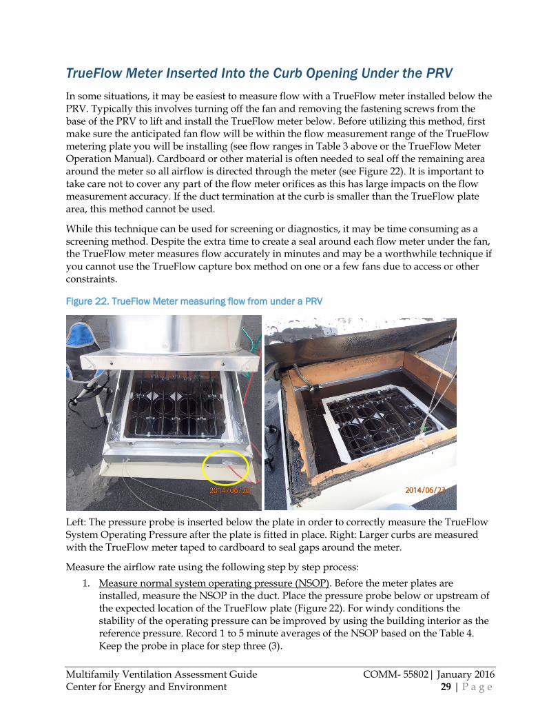
TrueFlow Meter Inserted Into the Curb Opening Under the PRV In some situations, it may be easiest to measure flow with a TrueFlow meter installed below the PRV. Typically this involves turning off the fan and removing the fastening screws from the base of the PRV to lift and install the TrueFlow meter below. Before utilizing this method, first make sure the anticipated fan flow will be within the flow measurement range of the TrueFlow metering plate you will be installing (see flow ranges in Table 3 above or the TrueFlow Meter Operation Manual). Cardboard or other material is often needed to seal off the remaining area around the meter so all airflow is directed through the meter (see Figure 22). It is important to take care not to cover any part of the flow meter orifices as this has large impacts on the flow measurement accuracy. If the duct termination at the curb is smaller than the TrueFlow plate area, this method cannot be used.
While this technique can be used for screening or diagnostics, it may be time consuming as a screening method. Despite the extra time to create a seal around each flow meter under the fan, the TrueFlow meter measures flow accurately in minutes and may be a worthwhile technique if you cannot use the TrueFlow capture box method on one or a few fans due to access or other constraints.
Figure 22. TrueFlow Meter measuring flow from under a PRV
Left: The pressure probe is inserted below the plate in order to correctly measure the TrueFlow System Operating Pressure after the plate is fitted in place. Right: Larger curbs are measured with the TrueFlow meter taped to cardboard to seal gaps around the meter.
Measure the airflow rate using the following step by step process: 1. Measure normal system operating pressure (NSOP). Before the meter plates are
installed, measure the NSOP in the duct. Place the pressure probe below or upstream of the expected location of the TrueFlow plate (Figure 22). For windy conditions the stability of the operating pressure can be improved by using the building interior as the reference pressure. Record 1 to 5 minute averages of the NSOP based on the Table 4. Keep the probe in place for step three (3).

Multifamily Ventilation Assessment Guide COMM- 55802| January 2016 Center for Energy and Environment 30 | P a g e
2. Insert meter plates. Turn off the fan and insert the meter plates into the duct below the fan. Tape or add a support frame as necessary for an airtight fit, directing all airflow through the TrueFlow plate.
3. Measure TrueFlow system operating pressure (TFSOP) and plate flow rate. The TFSOP reference pressure location (inside or outside) should be consistent with NSOP location. Turn on the fan. Record 1 to 5 minute averages of the TFSOP based on Table 4 above. Similarly record 1 to 5 minute average values for each metering plate. If your gauge reads flow directly, record the flow rate. If you recorded the plate pressure(s), use the equations below to compute flow rates from the meter plate pressure(s):
𝑴𝑴𝑴𝑴𝑴𝑴𝑴𝑴𝑴𝑴𝑴𝑴𝑴𝑴𝑴𝑴 𝒑𝒑𝒑𝒑𝒑𝒑𝑴𝑴𝑴𝑴 #𝟏𝟏𝟏𝟏:𝑭𝑭𝒑𝒑𝑭𝑭𝑭𝑭 (𝒄𝒄𝒄𝒄𝒄𝒄) = 𝟏𝟏𝟏𝟏𝟏𝟏 × (𝑻𝑻𝑴𝑴𝑻𝑻𝑴𝑴𝑭𝑭𝒑𝒑𝑭𝑭𝑭𝑭 𝑷𝑷𝒑𝒑𝒑𝒑𝑴𝑴𝑴𝑴 𝑷𝑷𝑴𝑴𝑴𝑴𝑷𝑷𝑷𝑷𝑻𝑻𝑴𝑴𝑴𝑴,𝑷𝑷𝒑𝒑)𝟎𝟎.𝟏𝟏
𝑴𝑴𝑴𝑴𝑴𝑴𝑴𝑴𝑴𝑴𝑴𝑴𝑴𝑴𝑴𝑴 𝒑𝒑𝒑𝒑𝒑𝒑𝑴𝑴𝑴𝑴 #𝟐𝟐𝟎𝟎:𝑭𝑭𝒑𝒑𝑭𝑭𝑭𝑭 (𝒄𝒄𝒄𝒄𝒄𝒄) = 𝟏𝟏𝟏𝟏𝟏𝟏 × (𝑻𝑻𝑴𝑴𝑻𝑻𝑴𝑴𝑭𝑭𝒑𝒑𝑭𝑭𝑭𝑭 𝑷𝑷𝒑𝒑𝒑𝒑𝑴𝑴𝑴𝑴 𝑷𝑷𝑴𝑴𝑴𝑴𝑷𝑷𝑷𝑷𝑻𝑻𝑴𝑴𝑴𝑴,𝑷𝑷𝒑𝒑)𝟎𝟎.𝟏𝟏
4. Return to normal operating conditions. Turn off the PRV, remove the device, seal the pressure probe hole and return the fan to normal operation.
5. Calculate the Flow Resistance Correction Factor. The Flow Resistance Correction Factor is used to compensate for the reduction in air flow caused by the metering plates. Use the NSOP and TFSOP to calculate the Flow Resistance Correction Factor based on the equation below from the TrueFlow Operation Manual:
𝑭𝑭𝒑𝒑𝑭𝑭𝑭𝑭 𝑹𝑹𝑴𝑴𝑷𝑷𝑴𝑴𝑷𝑷𝑴𝑴𝒑𝒑𝑴𝑴𝒄𝒄𝑴𝑴 𝑪𝑪𝑭𝑭𝑴𝑴𝑴𝑴𝑴𝑴𝒄𝒄𝑴𝑴𝑴𝑴𝑭𝑭𝑴𝑴 𝑭𝑭𝒑𝒑𝒄𝒄𝑴𝑴𝑭𝑭𝑴𝑴 = �(𝑵𝑵𝑵𝑵𝑵𝑵𝑷𝑷/𝑻𝑻𝑭𝑭𝑵𝑵𝑵𝑵𝑷𝑷) 6. Compute Corrected Flow Rate. Sum the measured flow from each TrueFlow metering
plate and multiply by the Flow Resistance Correction Factor to determine the corrected airflow rate:
𝑻𝑻𝑭𝑭𝑴𝑴𝒑𝒑𝒑𝒑 𝑴𝑴𝒆𝒆𝒆𝒆𝒑𝒑𝑻𝑻𝑷𝑷𝑴𝑴 𝒄𝒄𝒑𝒑𝑭𝑭𝑭𝑭 (𝒄𝒄𝒄𝒄𝒄𝒄)= 𝑵𝑵𝑻𝑻𝒄𝒄 𝑭𝑭𝒄𝒄 𝒑𝒑𝒑𝒑𝒑𝒑 𝑻𝑻𝑴𝑴𝑻𝑻𝑴𝑴𝑭𝑭𝒑𝒑𝑭𝑭𝑭𝑭 𝒑𝒑𝒑𝒑𝒑𝒑𝑴𝑴𝑴𝑴 𝒄𝒄𝒑𝒑𝑭𝑭𝑭𝑭𝑷𝑷 (𝒄𝒄𝒄𝒄𝒄𝒄) × 𝑭𝑭𝒑𝒑𝑭𝑭𝑭𝑭 𝑹𝑹𝑴𝑴𝑷𝑷𝑴𝑴𝑷𝑷𝑴𝑴𝒑𝒑𝑴𝑴𝒄𝒄𝑴𝑴 𝑪𝑪𝑭𝑭𝑴𝑴𝑴𝑴𝑴𝑴𝒄𝒄𝑴𝑴𝑴𝑴𝑭𝑭𝑴𝑴 𝑭𝑭𝒑𝒑𝒄𝒄𝑴𝑴𝑭𝑭𝑴𝑴
A complete TrueFlow meter operation manual is available at: http://energyconservatory.com/wp-content/uploads/2014/07/TrueFlow-Manual-DG700.pdf
Supply Ventilation Measurement Central supply ventilation system energy savings is evaluated by comparing the measured to the desired outdoor airflow rate. A vane anemometer air inlet traverse is a fast and simple method to determine flow rates at a screening visit. Though less accurate than other diagnostic methods described in this manual, it can be used to effectively characterize ventilation flows and identify those above a threshold for energy savings potential. There are a number of ways to more accurately measure outdoor airflows for diagnostic purposes. Selecting an appropriate method depends on site conditions and access.
Appropriate methods of supply ventilation measurement include: a duct traverse of the outdoor air intake with a thermal anemometer, multiple TrueFlow meter plates custom sealed inside the outdoor air intake duct (or to the exterior intake grille), or a calibrated fan fit over the outdoor air intake grille to measure flow at matched pressure. An anemometer duct traverse requires access to an outdoor air duct intake location with somewhat uniform flow before any return air mixing. The custom TrueFlow frame can often be built to fit in the filter rack and is less sensitive to turbulence, so this method is the next best choice if there is not an ideal location

Multifamily Ventilation Assessment Guide COMM- 55802| January 2016 Center for Energy and Environment 31 | P a g e
to measure with the thermal anemometer. If there is no access to the outdoor air duct, as on a rooftop unit, the next best option is to fit a calibrated fan over the outdoor air intake and measure flow while matching normal system operating pressure. For systems with return air, another accurate and useful diagnostic airflow measurement technique is to measure the outside, return and supply or “mixed” air temperatures to calculate the percent outdoor air. The percentage is then multiplied by the measured supply airflow rate to determine the outdoor airflow rate. This method has some seasonal temperature limitations and cannot be used on systems without any or with low return airflow. For ventilation systems that provide 100% of conditioned outdoor air (meaning there is no return or recirculated air), the FlowBlasterTM capture hood described in an earlier section or other commercially available flow hood can be used to measure each supply grille airflow. The flows are then summed to determine the total system ventilation flow.
Note that the volumetric flow rate changes as the outdoor air is heated or cooled to inside conditions. If the outdoor air flow rate was measured before it was heated or cooled, you will always need to measure the outdoor air temperature and use the following equation to adjust for the difference between the outdoor and indoor (assumed to be 70F) air temperatures:
𝑵𝑵𝑻𝑻𝑴𝑴𝑶𝑶𝑭𝑭𝑭𝑭𝑴𝑴 𝒑𝒑𝑴𝑴𝑴𝑴𝒄𝒄𝒑𝒑𝑭𝑭𝑭𝑭 (𝒄𝒄𝒄𝒄𝒄𝒄)= 𝑵𝑵𝑻𝑻𝒄𝒄 𝑭𝑭𝒄𝒄 𝒄𝒄𝒑𝒑𝑴𝑴 𝒄𝒄𝒑𝒑𝑭𝑭𝑭𝑭𝑷𝑷 (𝒄𝒄𝒄𝒄𝒄𝒄) × (𝟏𝟏𝟒𝟒𝟎𝟎 + 𝑵𝑵𝑻𝑻𝑴𝑴𝑶𝑶𝑭𝑭𝑭𝑭𝑴𝑴 𝒑𝒑𝑴𝑴𝑴𝑴 𝑴𝑴𝑴𝑴𝒄𝒄𝒑𝒑𝑴𝑴𝑴𝑴𝒑𝒑𝑴𝑴𝑻𝑻𝑴𝑴𝑴𝑴,𝑭𝑭)/𝟏𝟏𝟒𝟒𝟎𝟎
Vane Anemometer Duct Traverse Rotating vane anemometers (Figure 23) can be used to measure intake flows to quickly assess whether a supply ventilation system is drawing excessive or inadequate outdoor airflow. The average flow rate is computed from the average velocity based on multiple measurements taken from the cross-section of the inlet. When selecting a van anemometer, those with a 2-3” vane generally cover a larger area and are more accurate than those with a 1” microvane.
This tool is adequate when screening a building for threshold high or low flows, but is not ideal in this application for high accuracy measurements and should not be used as a diagnostic tool (+/- 30% accuracy according to ASHRAE standard 111-2008). It can be used to approximate the airflow at outdoor air intake grilles or register supply grilles. Note that may vane anemometers do not register flow rates below 80 feet per minute and thus will not measure low flows or low flow portions of the duct (ASHRAE standard 111-2008 does not recommend the use of vanes for velocities below 100 feet per minute). The vane will also read less accurately as it travels from high to low velocity across a duct, as it takes time for the vane blades to decelerate. Measurements at outdoor air intake grilles exposed to windy conditions may further affect the measured flow rate accuracy. Though less accurate, vane anemometer traverses are useful as a low-cost method to provide a low-resolution measurement and determine if hiring a contractor to modify airflows will be a cost-effective investment.
See product manual or ASHRAE standard 111-2008 for more detailed description of measurement method.
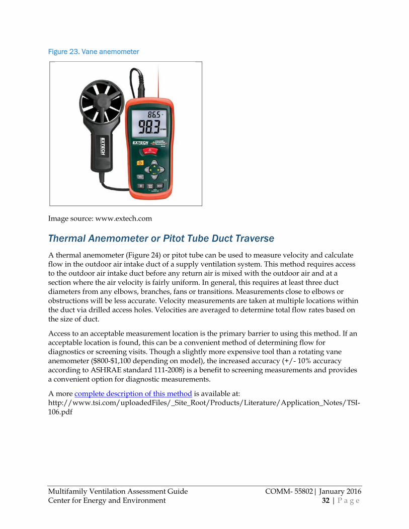
Multifamily Ventilation Assessment Guide COMM- 55802| January 2016 Center for Energy and Environment 32 | P a g e
Figure 23. Vane anemometer
Image source: www.extech.com
Thermal Anemometer or Pitot Tube Duct Traverse A thermal anemometer (Figure 24) or pitot tube can be used to measure velocity and calculate flow in the outdoor air intake duct of a supply ventilation system. This method requires access to the outdoor air intake duct before any return air is mixed with the outdoor air and at a section where the air velocity is fairly uniform. In general, this requires at least three duct diameters from any elbows, branches, fans or transitions. Measurements close to elbows or obstructions will be less accurate. Velocity measurements are taken at multiple locations within the duct via drilled access holes. Velocities are averaged to determine total flow rates based on the size of duct.
Access to an acceptable measurement location is the primary barrier to using this method. If an acceptable location is found, this can be a convenient method of determining flow for diagnostics or screening visits. Though a slightly more expensive tool than a rotating vane anemometer ($800-$1,100 depending on model), the increased accuracy (+/- 10% accuracy according to ASHRAE standard 111-2008) is a benefit to screening measurements and provides a convenient option for diagnostic measurements.
A more complete description of this method is available at: http://www.tsi.com/uploadedFiles/_Site_Root/Products/Literature/Application_Notes/TSI-106.pdf

Multifamily Ventilation Assessment Guide COMM- 55802| January 2016 Center for Energy and Environment 33 | P a g e
Figure 24. Measuring flow with hot wire anemometer
Photo courtesy TSI.com
Customized TrueFlow Meter Frame There are some situations where it may be easiest to measure air intake flow with multiple TrueFlow meters installed at the outdoor air intake duct. It is an accurate method for diagnostics and may be more convenient than conducting a duct traverse.
The filter rack may provide a good location to access the outdoor air duct and install the TrueFlow frame. First select a number of metering plates that will accommodate the anticipated duct flow rate. (Reference flow ranges in Table 3 above or in the TrueFlow Meter Operation Manual.) Cardboard or other airtight material is often needed to seal off the remaining area around the meter so all airflow is directed through the meter (see Figure 25). It is important to take care not to cover any part of the flow meter orifices as this has large impacts on the flow measurement accuracy.
Figure 25. TrueFlow meters installed into an outdoor air intake duct

Multifamily Ventilation Assessment Guide COMM- 55802| January 2016 Center for Energy and Environment 34 | P a g e
Measure the airflow rate using the following step by step process: 1. Measure normal system operating pressure (NSOP). Before the meter plates are
installed, measure the NSOP at a minimally turbulent location in the outdoor air intake duct. For windy conditions the stability of the operating pressure can be improved by using the building interior as the reference pressure. Record one minute averages of the NSOP. Keep the probe in place for step three (3).
2. Insert meter plates. Turn off the air handler, attach the frame and seal off the area around the frame for an airtight fit so that all airflow is directed through the metering plates.
3. Measure TrueFlow system operating pressure (TFSOP) and plate flow rate. The TFSOP reference pressure location (inside or outside) should be consistent with NSOP location. Turn on the air handler and record one minute averages of the TFSOP for each metering plate. If your gauge reads flow directly, record the flow rate. If you recorded the plate pressure(s), use the equations below to compute flow rates from the meter plate pressure(s):
𝑴𝑴𝑴𝑴𝑴𝑴𝑴𝑴𝑴𝑴𝑴𝑴𝑴𝑴𝑴𝑴 𝒑𝒑𝒑𝒑𝒑𝒑𝑴𝑴𝑴𝑴 #𝟏𝟏𝟏𝟏:𝑭𝑭𝒑𝒑𝑭𝑭𝑭𝑭 (𝒄𝒄𝒄𝒄𝒄𝒄) = 𝟏𝟏𝟏𝟏𝟏𝟏 × (𝑻𝑻𝑴𝑴𝑻𝑻𝑴𝑴𝑭𝑭𝒑𝒑𝑭𝑭𝑭𝑭 𝑷𝑷𝒑𝒑𝒑𝒑𝑴𝑴𝑴𝑴 𝑷𝑷𝑴𝑴𝑴𝑴𝑷𝑷𝑷𝑷𝑻𝑻𝑴𝑴𝑴𝑴,𝑷𝑷𝒑𝒑)𝟎𝟎.𝟏𝟏
𝑴𝑴𝑴𝑴𝑴𝑴𝑴𝑴𝑴𝑴𝑴𝑴𝑴𝑴𝑴𝑴 𝒑𝒑𝒑𝒑𝒑𝒑𝑴𝑴𝑴𝑴 #𝟐𝟐𝟎𝟎:𝑭𝑭𝒑𝒑𝑭𝑭𝑭𝑭 (𝒄𝒄𝒄𝒄𝒄𝒄) = 𝟏𝟏𝟏𝟏𝟏𝟏 × (𝑻𝑻𝑴𝑴𝑻𝑻𝑴𝑴𝑭𝑭𝒑𝒑𝑭𝑭𝑭𝑭 𝑷𝑷𝒑𝒑𝒑𝒑𝑴𝑴𝑴𝑴 𝑷𝑷𝑴𝑴𝑴𝑴𝑷𝑷𝑷𝑷𝑻𝑻𝑴𝑴𝑴𝑴,𝑷𝑷𝒑𝒑)𝟎𝟎.𝟏𝟏
4. Return to normal operating conditions. Remove the plates, seal the pressure probe hole and return the air handler to normal operation.
5. Calculate the Flow Resistance Correction Factor. The Flow Resistance Correction Factor is used to compensate for the reduction in airflow caused by the metering plates. Use the NSOP and TFSOP to calculate the Flow Resistance Correction Factor based on the equation below from the TrueFlow Operation Manual:
𝑭𝑭𝒑𝒑𝑭𝑭𝑭𝑭 𝑹𝑹𝑴𝑴𝑷𝑷𝑴𝑴𝑷𝑷𝑴𝑴𝒑𝒑𝑴𝑴𝒄𝒄𝑴𝑴 𝑪𝑪𝑭𝑭𝑴𝑴𝑴𝑴𝑴𝑴𝒄𝒄𝑴𝑴𝑴𝑴𝑭𝑭𝑴𝑴 𝑭𝑭𝒑𝒑𝒄𝒄𝑴𝑴𝑭𝑭𝑴𝑴 = �(𝑵𝑵𝑵𝑵𝑵𝑵𝑷𝑷/𝑻𝑻𝑭𝑭𝑵𝑵𝑵𝑵𝑷𝑷) 6. Compute Corrected Flow Rate. Sum the measured flow from each TrueFlow metering
plate and multiply by the Flow Resistance Correction Factor to determine the corrected airflow rate:
𝑵𝑵𝑻𝑻𝑴𝑴𝑶𝑶𝑭𝑭𝑭𝑭𝑴𝑴 𝒑𝒑𝑴𝑴𝑴𝑴𝒄𝒄𝒑𝒑𝑭𝑭𝑭𝑭 (𝒄𝒄𝒄𝒄𝒄𝒄)= 𝑵𝑵𝑻𝑻𝒄𝒄 𝑭𝑭𝒄𝒄 𝒑𝒑𝒑𝒑𝒑𝒑 𝑻𝑻𝑴𝑴𝑻𝑻𝑴𝑴𝑭𝑭𝒑𝒑𝑭𝑭𝑭𝑭 𝒑𝒑𝒑𝒑𝒑𝒑𝑴𝑴𝑴𝑴 𝒄𝒄𝒑𝒑𝑭𝑭𝑭𝑭𝑷𝑷 (𝒄𝒄𝒄𝒄𝒄𝒄) × 𝑭𝑭𝒑𝒑𝑭𝑭𝑭𝑭 𝑹𝑹𝑴𝑴𝑷𝑷𝑴𝑴𝑷𝑷𝑴𝑴𝒑𝒑𝑴𝑴𝒄𝒄𝑴𝑴 𝑪𝑪𝑭𝑭𝑴𝑴𝑴𝑴𝑴𝑴𝒄𝒄𝑴𝑴𝑴𝑴𝑭𝑭𝑴𝑴 𝑭𝑭𝒑𝒑𝒄𝒄𝑴𝑴𝑭𝑭𝑴𝑴
7. Compute Temperature Corrected Flow Rate. The volumetric flow rate changes as the outdoor air is heated or cooled to inside conditions. Measure the outdoor air temperature and use the following equation to adjust for the difference between the outdoor and indoor (assumed to be 70F) air temperatures:
𝑵𝑵𝑻𝑻𝑴𝑴𝑶𝑶𝑭𝑭𝑭𝑭𝑴𝑴 𝒑𝒑𝑴𝑴𝑴𝑴𝒄𝒄𝒑𝒑𝑭𝑭𝑭𝑭 (𝒄𝒄𝒄𝒄𝒄𝒄)= 𝑵𝑵𝑻𝑻𝑴𝑴𝑶𝑶𝑭𝑭𝑭𝑭𝑴𝑴 𝒑𝒑𝑴𝑴𝑴𝑴𝒄𝒄𝒑𝒑𝑭𝑭𝑭𝑭 (𝒄𝒄𝒄𝒄𝒄𝒄) × (𝟏𝟏𝟒𝟒𝟎𝟎 + 𝑵𝑵𝑻𝑻𝑴𝑴𝑶𝑶𝑭𝑭𝑭𝑭𝑴𝑴 𝒑𝒑𝑴𝑴𝑴𝑴 𝑴𝑴𝑴𝑴𝒄𝒄𝒑𝒑𝑴𝑴𝑴𝑴𝒑𝒑𝑴𝑴𝑻𝑻𝑴𝑴𝑴𝑴,𝑭𝑭)/𝟏𝟏𝟒𝟒𝟎𝟎
A complete TrueFlow meter operation manual is available at: http://energyconservatory.com/wp-content/uploads/2014/07/TrueFlow-Manual-DG700.pdf

Multifamily Ventilation Assessment Guide COMM- 55802| January 2016 Center for Energy and Environment 35 | P a g e
Percent Outdoor Air Temperature Difference Method The outdoor airflow rate can sometimes be computed from a measurement of the supply airflow multiplied by the fraction of outdoor air. This method is appropriate when the system has building return air to the air handler, the supply flow rate is easier to measure than the outdoor air flow rate, and the difference in outdoor to indoor temperature is at least 10 to 15 degrees. The supply flow rate can be measured by conducting a traverse of the supply duct or using the FlowBlasterTM or other capture hood to measure the supply grille flow rates. After determining total supply flow, the next step is to take three temperature readings and calculate the percent of outdoor air using the following equation:
%𝑂𝑂𝑂𝑂𝑂𝑂𝑂𝑂𝑂𝑂𝑂𝑂𝑂𝑂 𝑎𝑎𝑎𝑎𝑂𝑂 =𝑇𝑇(𝑂𝑂𝑟𝑟𝑂𝑂𝑂𝑂𝑂𝑂𝑟𝑟 𝑎𝑎𝑎𝑎𝑂𝑂) − 𝑇𝑇(𝑠𝑠𝑂𝑂𝑠𝑠𝑠𝑠𝑠𝑠𝑠𝑠 𝑎𝑎𝑎𝑎𝑂𝑂)𝑇𝑇(𝑂𝑂𝑟𝑟𝑂𝑂𝑂𝑂𝑂𝑂𝑟𝑟 𝑎𝑎𝑎𝑎𝑂𝑂) − 𝑇𝑇(𝑂𝑂𝑂𝑂𝑂𝑂𝑂𝑂𝑂𝑂𝑂𝑂𝑂𝑂 𝑎𝑎𝑎𝑎𝑂𝑂)
The method requires outdoor air, mixed (supply) air and return air temperature measurements. To ensure accuracy, the readings need to be taken at specific locations. Outdoor air must be measured at the outdoor air inlet, the supply air must be measured before the air has been heated or cooled, and the return air must be measured as close to the air handling unit as possible before it is mixed with outdoor air. Temperature measurements should also be taken before any fans, since a fan will increase the temperature up to a few degrees.
One barrier to this method is that it can be difficult to find access to measure all three temperatures at their ideal locations. This method is also limited seasonally as it is much less accurate when the outdoor air temperature is within 10 degrees of the return air temperature. However, it can be an accurate method for diagnostic measurements and may be the preferred method where there is no ideal location to perform a duct traverse with a thermal anemometer in the outdoor air intake duct before the outdoor air it mixes with return air.
A more complete description of this method is described available at: http://www.tsi.com/uploadedFiles/_Site_Root/Products/Literature/Application_Notes/AF-138%20Percent%20Outside%20Air.pdf
Outdoor Air Grille: Calibrated Fan with Pressure Matching The outdoor airflow rate can also be measured with a calibrated fan fitted to cover the outdoor air intake. The fan speed is adjusted until the duct pressure is equal to the pressure under normally operating conditions. This method is useful when duct access or site conditions do not allow for other measurement methods used inside the outdoor air intake duct. A single or multiple blower door fan(s) or duct blaster can be fitted to a customized frame or an adapted blower door frame that covers the outdoor air intake of a ventilation unit (Figure 26). A digital pressure gauge, such as The Energy Conservatory’s DG-700, can be set to measure airflow while matching normal system operating pressure. Select appropriate fans with flow capacity to accommodate the approximate anticipated flow through the grille and determine how you will attach and seal the fan(s) to the grille.
If the grille is large enough, a triple blower door fan frame and canvas works well as a pre-built support structure for blower door fans and can be strapped to the grille and sealed at its perimeter with duct mask (Figure 26). If the intake grille is hooded, flexible polyethylene flow tubes (Figure 26) can provide flexible attachment to the fans. Once you decide how to attach

Multifamily Ventilation Assessment Guide COMM- 55802| January 2016 Center for Energy and Environment 36 | P a g e
and seal your fan to the intake, turn off the air handler and install the fans to the intake grille, taking care to seal the entire surface with tape or other air barrier for an airtight seal. Mask off the open area, directing all airflow through the fan. Then turn on the air handler and adjust the calibrated fan (s) to match the normal system operating duct pressure at the same location as was originally measured. Take a flow reading with the pressure gauge at this matched pressure.
Measure the airflow rate using the following step by step process: 1. Measure normal system operating pressure (NSOP). Before the fans are installed,
measure the NSOP at a minimally turbulent location in the outdoor air intake duct. For windy conditions the stability of the operating pressure can be improved by using the building interior as the reference pressure. Record one minute averages of the NSOP and keep the probe in place for step three (3).
2. Install calibrated fans. Turn off the air handler, attach the frame and seal off the area around the fan(s) for an airtight fit so that all airflow is directed through the fans.
3. Measure fan flow rate. The reference pressure location (inside or outside) should be consistent with the NSOP location. Turn on the air handler. Adjust the speed of the calibrated fan(s) until the duct pressure is equal to the NSOP. Record one minute average flow rates for each calibrated fan.
4. Return to normal operating conditions. Remove the fan(s), seal the pressure probe hole and return the air handler to normal operation.
5. Compute Temperature Corrected Flow Rate. The volumetric flow rate changes as the outdoor air is heated or cooled to inside conditions. Measure the outdoor air temperature and use the following equation to adjust for the difference between the outdoor and indoor (assumed to be 70F) air temperatures:
𝑵𝑵𝑻𝑻𝑴𝑴𝑶𝑶𝑭𝑭𝑭𝑭𝑴𝑴 𝒑𝒑𝑴𝑴𝑴𝑴𝒄𝒄𝒑𝒑𝑭𝑭𝑭𝑭 (𝒄𝒄𝒄𝒄𝒄𝒄)= 𝑵𝑵𝑻𝑻𝒄𝒄 𝑭𝑭𝒄𝒄 𝒄𝒄𝒑𝒑𝑴𝑴 𝒄𝒄𝒑𝒑𝑭𝑭𝑭𝑭𝑷𝑷 (𝒄𝒄𝒄𝒄𝒄𝒄) × (𝟏𝟏𝟒𝟒𝟎𝟎 + 𝑵𝑵𝑻𝑻𝑴𝑴𝑶𝑶𝑭𝑭𝑭𝑭𝑴𝑴 𝒑𝒑𝑴𝑴𝑴𝑴 𝑴𝑴𝑴𝑴𝒄𝒄𝒑𝒑𝑴𝑴𝑴𝑴𝒑𝒑𝑴𝑴𝑻𝑻𝑴𝑴𝑴𝑴,𝑭𝑭)/𝟏𝟏𝟒𝟒𝟎𝟎
Pressure matching with fans is significantly more time consuming and equipment intensive than conducting a traverse with a thermal anemometer or pitot or measuring with a TrueFlow meters. However, it can be a useful diagnostic tool where airflow exceeds the flow capacity of the maximum number of TrueFlow meters that will fit in the open area of the duct/intake or when there is no access to outdoor air ducts for a traverse.
More detailed instructions on “pressure matching” method (using Duct Blaster fans) can be found at: http://energyconservatory.com/wp-content/uploads/2014/07/Duct-Blaster-Manual-Series-B-DG700.pdf, Chapter 13.1 Measuring Total System Airflow. Instructions are written for flow measurement in a residential air handler but a similar process can followed for a commercial air handler.

Multifamily Ventilation Assessment Guide COMM- 55802| January 2016 Center for Energy and Environment 37 | P a g e
Figure 26. Blower door fans adapted to measure air intake flow using the “pressure matching” method.

Multifamily Ventilation Assessment Guide COMM- 55802| January 2016 Center for Energy and Environment 38 | P a g e
Conducting Ventilation Assessments The remaining sections of this document describe the process of assessing central supply and exhaust ventilation systems and trash chutes in multifamily buildings. The basic steps are shown in the diagram below.

Multifamily Ventilation Assessment Guide COMM- 55802| January 2016 Center for Energy and Environment 39 | P a g e
Step 1—Phone Survey Objective: Gather basic information over the phone to determine whether a building is a
good candidate for a ventilation assessment. This survey screens for buildings that have central ventilation systems and have concerns or complaints that may be related to building ventilation issues.
Equipment needed • Building contact phone number
• Field form “Multifamily Ventilation: Phone Survey” Time required: 15 or less minutes Key details
• The best option is to conduct the survey with the building operator (this could also be a maintenance director or maintenance manager for the building) to gather accurate information regarding the equipment and the operations history of the equipment. If a building operator is not available, the survey can be conducted with a property manager, property owner or building caretaker.
• The phone survey incorporates multiple terms to describe central ventilation systems to catch as many assessment opportunities as possible. Use familiar and basic terms to describe ventilation systems and system components to get the most accurate and consistent information.
Sample Script
• Hello my name is ___(name)___ and I am a multifamily building assessor for _(your organization)_. I was asked by _(name of initial contact for property)_ to look at energy savings opportunities for your building’s ventilation system. I have a few questions that are probably best answered by your building engineer, a representative of your maintenance staff, or you, if you are in charge of day to day equipment operations. I would like to determine if your building’s ventilation equipment has energy savings potential and is worth a closer look by our building analysts. I have about 15 minutes of questions to ask over the phone to get the information I need. Can you put me in contact with the person you think would be best to answer these questions?
Survey Questions and Form • See Appendix 1: Multifamily Ventilation Assessment: Phone Survey form for complete list
of survey questions.
Step 2—Building Ventilation Screening Visit Objective: Use tools and methods that are accessible to most energy auditors to identify
significant energy savings opportunities associated with reducing ventilation flow. Additionally, identify major ventilation distribution issues or other deficiencies. This step can be skipped if the building owner(s) is already aware of significant ventilation issues and motivated to invest in resolving them.
Responsible party: Building energy analyst/energy auditor or HVAC professional

Multifamily Ventilation Assessment Guide COMM- 55802| January 2016 Center for Energy and Environment 40 | P a g e
Equipment /supplies needed
• General tools from Ventilation Assessment tool list (Appendix 3)
• Equipment for airflow measurement method selected from “Airflow measurement methods” section of this document
• Building mechanical blue prints (if available)
• Field Form: Multifamily Ventilation Assessment: Building Screening form (Appendix 2)
• Resident Notification form
• Building screening decision trees (Appendix 5.1, 5.2, 5.3) Time required: Approximately 1-3 hours Key details:
• Review the “Airflow Measurement Methods” section of this document for a list of applicable measurement techniques.
• Request that the building operator, maintenance staff or designated building operator be present at the start of the visit to answer questions about problems, adjustments and modifications to building equipment.
• Take photographs to help reinforce findings and prevent multiple trips to verify settings, measurements or configurations.
• Use building blue prints or construction plans when possible to better understand equipment, duct, damper and register locations and system operation, and if possible either photograph or copy building plans for later reference.
• Check that blue prints are consistent with existing building conditions (i.e.no significant modifications have been made that blue prints do not document).
Conducting the Building Ventilation Screening Visit There are 2 main approaches that can be used to conduct the measurements required for screening the exhaust ventilation system, which are referred to as method A and method B. Method A requires access to more apartments for exhaust measurement at inlets, while method B requires access to only 1 or 2 apartments and measurements taken primarily at the exhaust outlet, which is typically on the roof. The responsible party can conduct the measurements using either method A or B, taking in to account which is more cost effective given building access conditions. However, the selected method must be followed to completion, meaning that if method A is selected, all of the tasks listed for Method A must be completed. 1. Scheduling details
1.1. Personnel. Arrange a meeting with the building engineer (or personnel in charge of building operations/routine equipment checks) during the screening visit.
• 20-30 minutes of staff time is needed for building tour and operational questions.
• If possible, obtain building mechanical plans/blue prints in advance.
Multifamily Ventilation Assessment Guide COMM- 55802| January 2016 Center for Energy and Environment 41 | P a g e
1.2. Mechanical room and roof access. Screening visit requires access to all mechanical rooms, boiler rooms, rooftop and common areas.
1.3. Apartment access. Building management will need to notify residents of apartment entry in a sampling of apartments. The number of units depends on screening method selected.
• Provide a resident notification form as a convenience to building management. (See example Resident Notification form provided in Appendix 4).
2. Inspecting site exterior
• Walk around all sides of the building, noting any visible air intakes/exhaust terminations.
3. Building orientation 3.1. Interview building engineer
• Use the Building Screening - Multifamily Ventilation Assessment form to record answers to building operations questions.
• Gain an understanding of engineer’s approach to running building equipment throughout the year.
• Get a lead on any issues that could indicate over or under-ventilating. 4. Building inspection. For each area type inspected, fill out the Building Screening Form.
4.1. Central exhaust screen.
Exhaust screening method A: Access apartments at the top and bottom of all shafts and determine recommendation based on inlet flows.
Apartment units, method A: Inspect a minimum of 2 apartments per shaft. Inspect an upper and lower floor apartment unit on each shaft, or each unique shaft type. 4.1.1. Measure apartment area (ft²) and determine apartment exhaust flow target
• See “Determining Ventilation Airflow Targets in MN Multifamily Buildings” section of this document
4.1.2. Note location of any central ventilation (supply or exhaust) register grilles/hoods
4.1.3. Measure inlet flow at any central ventilation flow grilles (cfm).
• Use a screening measurement method referenced in the “Airflow Measurement Methods” chapter of this document
• If any inlet measured is shut or the flow is blocked, note the condition before opening the inlet for measurement. When the measurement is complete, return inlet to as-found conditions.
• If any inlet is clogged or disconnected, note the condition and then measure another nearby inlet on the same shaft that has measureable airflow for inclusion in the threshold CFM excess calculation.
Multifamily Ventilation Assessment Guide COMM- 55802| January 2016 Center for Energy and Environment 42 | P a g e
• These measurements will be used to determine the recommendation for the exhaust system according to part A of the Central Exhaust Decision Tree (Appendix 5.2).
4.1.4. Remove register grill (if possible) and inspect the ducts of 1 to 2 of each type of inlets.
• Note any flow regulating devices.
• Note condition of duct and components (i.e. are they disconnected or are there major air leaks?).
• Note duct damper position, if present (i.e. is it open, closed or partially closed?).
• Note air leakage between duct and ceiling finish. 4.1.5. Look for and make note of any evidence of moisture or odor problems, such as:
• Moisture, mold or rot at window sill;
• Window condensation;
• Moldy bathroom walls and/or ceiling; or
• Peeling paint.
Central exhaust fans, method A 4.1.6. Note type and operability (flow or no flow) of each exhaust fan.
• Type: Belt driven or direct drive (note if there is speed control).
• Operability: How many are not working (i.e. there is no motor sound or no airflow).
• Recommend to replace any inoperable fans with Electrically Commutated fans with speed controls.
• Recommend to replace all other fans upon failure with Electrically Commutated fans with speed controls.
4.1.7. If possible, power off and lift 1 to 2 PRV fans to inspect condition of shaft and note if shafts are intact or discontinuous.
4.1.8. Record any reported issues with the system operation or performance. 4.1.9. Record any reported instances of odors, moisture or condensation in the areas
these fans serve.
Exhaust screening method B: Access fewer apartments and conduct most measurements on the exhaust outlet (typically located on the rooftop).
Apartment units, method B: Inspect at least 2 apartment units on 2 representative exhaust shafts. Include 2 apartments near the top of the building (upper story) and 2 near the bottom of the building (lower story).

Multifamily Ventilation Assessment Guide COMM- 55802| January 2016 Center for Energy and Environment 43 | P a g e
4.1.10. Measure apartment area (ft²). 4.1.11. Note location of any central ventilation (supply or exhaust) register
grilles/hoods 4.1.12. Measure inlet flow at any central ventilation flow grilles (cfm).
• Use a screening measurement method referenced in the “Airflow Measurement Methods” chapter of this document.
• If any inlet measured is shut or the flow is blocked note the condition before opening the inlet for measurement. When the measurement is complete, return the inlet to as-found conditions.
• If any inlet is clogged or disconnected, note the condition and then measure another nearby inlet on the same shaft that has measureable airflow for inclusion in the threshold CFM excess calculation.
4.1.13. Remove register grill (if possible) and inspect duct at 1-4 inlets
• Note any flow regulating devices.
• Note condition of duct and components (i.e. are they disconnected or are there major air leaks?).
• Note duct damper position, if present (i.e. is it open, closed or partially closed?).
• Note air leakage between duct and ceiling finish. 4.1.14. Look for and make note of any evidence of moisture or odor problems, such as:
• Moisture, mold or rot at window sill;
• Window condensation;
• Moldy bathroom walls and/or ceiling; or
• Peeling paint.
Exhaust fans, method B.
4.1.15. Note type and operability (flow or no flow) of each exhaust fan.
• Type: Belt driven or direct drive (note if there is speed control).
• Operability: How many are not working (i.e. there is no motor sound or no airflow).
• Recommend to replace any inoperable fans with Electrically Commutated fans with speed controls.
• Recommend to replace all other fans upon failure with Electrically Commutated fans with speed controls.
4.1.16. If possible, power off and lift 1 to 2 PRV fans to inspect condition of shaft and note if they are intact or discontinuous.
4.1.17. Record any reported issues with the system operation or performance. 4.1.18. Record any reported instances of odors, moisture or condensation in the areas
these fans serve to build a case for upgrading the system, if necessary.

Multifamily Ventilation Assessment Guide COMM- 55802| January 2016 Center for Energy and Environment 44 | P a g e
4.1.19. Measure and record the exhaust flow of at least 2 of each unique exhaust fan and shaft configurations. • Determine the required ventilation for the shaft by calculating the
requirement for all of the units it serves. Use the mechanical blue prints and/or knowledge of the building operator.
• If 2 exhaust fans of the same type are measured at greater than 40% flow difference from each other, measure flow at 2 additional fans of that type. Average all measured flows of a certain shaft type to characterize each unique fan/shaft configuration.
• Use a screening measurement method referenced in the “Airflow Measurement Methods” section of this document.
4.1.20. Use the Central Exhaust Screening Decision Tree (Appendix 5.2, part B) to determine recommendations.
4.2. Screening central supply ventilation air handlers 4.2.1. Inspect all corridor air handlers. 4.2.2. Record the type or types of heating and cooling the air handler(s) provides (if
any). 4.2.3. Record the hours of run time for each air handler unit. 4.2.4. Measure the square footage of corridor or common area served by the system.
• This can be determined by viewing the mechanical blue prints. If no blue prints are available, measure the areas in the building.
4.2.5. Measure outdoor air intake airflow at all rooftop central supply air handlers.
• Use a screening measurement method referenced in the “Airflow Measurement Methods” section of this document.
4.2.6. Calculate ventilation overage for area served.
• Ventilation overage = Measured flow – Required flow for area served. 4.2.7. Use the Central Corridor Ventilation Decision Tree (Appendix 5.3) to make
recommendation for each air handler based on the measured flow rates. 4.2.8. Note any odors or history of odor complaints. 4.2.9. Note any history of adjustments or retrofits to the system. 4.2.10. Note any history of complaints regarding the system performance.
4.3. Trash chute screening Trash room inspection 4.3.1. Measure floor area of trash room (ft²). 4.3.2. Inspect for and recommend to air seal any penetrations connecting the building
air to the trash room air. 4.3.3. Measure flow of exhaust fan(s) in trash room(s) if present and determine overage
(cfm).

Multifamily Ventilation Assessment Guide COMM- 55802| January 2016 Center for Energy and Environment 45 | P a g e
• Use a screening measurement method described in the “Airflow Measurement Methods” section of this document.
• Recommended exhaust flow for trash rooms is 1 cfm / ft² room area
4.3.4. Note any excessive trash odors in hallways near room(s) or any history of trash odor complaints.
Rooftop trash chute termination inspection 4.3.5. Measure the total open exhaust area of the trash rooftop termination (in²). 4.3.6. Use the Trash Chute Decision Tree (Appendix 5.1) to determine
recommendation. 5. Analysis & Recommendations
Determine ventilation recommendations based on observations and measurements from the completed Building Screening form and using the Screening Decision Trees (Appendices 5.1, 5.2, 5.2).
Screening Decision Tree recommendations are based on threshold inefficiencies, which upon retrofitting will provide minimum energy saving paybacks of approximately 8 years or less (on average). Generally the more measured airflow exceeds the threshold airflow rates on the decision trees, the more aggressive the payback. Actual retrofit payback will depend on the work scope that is determined from the more in-depth diagnostic visit. While paybacks on ventilation retrofits can be as low as 2 months and as high as 8 years, they commonly range from 3-6 years.
• For the decision tree, recommendations are based on buildings heated with natural gas and retrofit cost assumptions are based on average contractor costs (listed below). If building heat is electric or another fuel type, general payback assumptions will be different and threshold flow rates may need to be adjusted.
• Exhaust system PRV replacement: $1,500/fan.
• Exhaust inlet orifice installation: $100/inlet.
• Fan/motor re-sheave: $3,000/air handler.
• If retrofit costs are lower due to building conditions (i.e. fans with speed controls are already installed) and only need adjustment, the following simple calculation for energy savings can be used to determine an approximate payback:
• 1 CFM ≈ $1 annual energy savings 5.2. Present a written report of recommendations from the decision tree. Include any
observed ventilation issues that may be resolved by improving the ventilation system.
See an example of Ventilation Findings report in Appendix 6 of this document. 5.2.1. Stress non-energy benefits, such as:
• Reduced draftiness in over-ventilated units; • More equitable ventilation flow distribution; • Reduced humidity (prolonged life of finishes such as paint and
caulks/sealants); and

Multifamily Ventilation Assessment Guide COMM- 55802| January 2016 Center for Energy and Environment 46 | P a g e
• Reduced maintenance/upkeep. 5.2.2. Address specific issues observed in the building in addition to energy savings
potential
Suggested report messaging based on observations: • Odors and moisture from low or unbalanced ventilation can affect resident
comfort and increase frequency of resident complaints. • Excess humidity resulting from low ventilation flow rates can increase
maintenance costs at time of apartment turnover with things like repainting, caulking and cleaning up mold or mildew.
• Retrofitting the ventilation system will provide opportunity to unclog any clogged, blocked or disconnected inlets and ensure balanced flow to all units.
• Replacing belts on belt-driven fans is an added maintenance expense that will be alleviated with upgraded fans.
• Replacement of belt-driven PRV fans with electrically commutated (EC) motors generally payback in electricity savings over their lifespan (10 years). If the fans will also be turned down to reduce ventilation, the payback period is reduced further.
• Paybacks for PRV replacement, orifice installation and fan turndown range on average from 5-6 years. Paybacks can be as low as 2 years and as high as 10 years.
5.2.3. Note potential duct leakage issues that should be addressed before reducing ventilation flow. • If the shaft observed under the PRV was noted as discontinuous (i.e.
disconnected or has other major gaps or leaks) or there were other indications of significant duct leakage, have an HVAC professional investigate duct leakage before pursuing ventilation flow modifications. Duct leakage may be causing flow distribution problems that will need to be addressed before reducing ventilation flow.
5.2.4. Explain post-retrofit verification process and quality assurance measures. 5.2.5. Discuss next step, such as completing diagnostics and developing a work scope.
• Provide contractor referrals and financing resources. 5.2.6. Obtain authorization to implement next step.
Step 3—Building Ventilation Diagnostics Objective: Use effective tools and methods to determine the cause and extent of the
ventilation problem and calculate the energy savings potential. • Identify work scope items that will improve ventilation performance and reduce
operation costs. • Generate a report for the building owner that outlines ventilation modifications
required for their building along with energy savings potential and payback analysis.

Multifamily Ventilation Assessment Guide COMM- 55802| January 2016 Center for Energy and Environment 47 | P a g e
Responsible party: HVAC professional or building energy analyst/auditor. Equipment
• Multifamily Ventilation Assessment: Building Diagnostic form (Appendix 6). • Resident Notification form (Appendix 3). • Building mechanical blue prints (if available). • Tools—see Ventilation Assessment Tool List (Appendix 3). • Equipment associated with selected airflow measurement methods
Time required: Approximately 16 field hours and 8 office hours. Key details
• The “Airflow Measurement Methods” section lists applicable measurement techniques.
• Request the building engineer, maintenance staff or designated building operator be present at the start of the visit to answer any questions about problems, adjustments and modifications to building equipment.
• Take photographs to help reinforce findings and prevent multiple trips to verify settings, measurements and/or configurations.
Site Visit Preparation 1. Personnel. Arrange a meeting with the building operator (or personnel in charge of
building operations and routine equipment checks). 2. Mechanical room and roof access. Diagnostics require access to all mechanical rooms,
boiler rooms and rooftop and common areas. • 30-40 minutes of staff time is needed for building tour and a few operational questions. • Obtain building mechanical plans and blue prints in advance (if possible).
3. Apartment access. Building management will need to notify residents of apartment entry. • Measure the airflow rate of apartment exhaust air inlets on a representative sample of
shafts (see section 3.1.7 below for sampling details). • Provide “Resident Notification” form (Appendix 3) for customer convenience and
expedited communication. 4. Preparation for the diagnostics. Obtain as much information about the building before the
building visit in order to expedite ventilation diagnostics. • If possible, obtain building blue prints in advance of the building visit. • Assemble equipment you will need to measure ventilation airflows.
• May be helpful to conduct a phone survey with building operator ahead of time to gather as much information about equipment as possible.
Building Ventilation Diagnostics 1. Inspect site exterior
1.1. Note air intakes and exhaust termination locations and make sure they are consistent with blue prints (i.e. that there are no significant changes to system that are not noted on the blue prints).
2. Tour mechanical rooms and common areas and conduct operator interview. Gain an understanding of ventilation operation, performance and building operation concerns. 2.1. Ensure systems and building configuration is consistent with blue prints.

Multifamily Ventilation Assessment Guide COMM- 55802| January 2016 Center for Energy and Environment 48 | P a g e
2.1.1. Clearly note any changes from prints (e.g. first floor rehab changed floor plan and space use, requiring different ventilation rates per room. Noted new room types and revised floor areas.).
2.2. Note space heating and cooling type. • Document space heating and cooling system efficiencies.
3. Diagnostic process 3.1. Central exhaust system diagnostics.
Powered Rooftop Ventilators (PRVs) 3.1.1. Determine whether the fans are belt driven or direct drive.
Work scope items:
• If belt driven, specify replacement of any belt-driven fans with electrically commutated motors with integral speed controls that are properly sized for individual shaft flow rates. • Electricity savings from fan upgrades generally pay for themselves
within the life of the fan; speed controls are important for fine-tuning fan flow.
• If direct drive, specify adding speed controls to any direct drive fans without speed controls.
• Optional: Measure watt usage on each fan to determine the exact payback of fan upgrades. Actual power use often varies from rated power use, often by up to +/-50-80%.
• If belt driven fans are new or recently modified and the building owner is not motivated to invest in new fans, specify re-sheave of existing fans (adjusting or replacing pulleys for reduced flow), but first consider the following reasons to replace a belt-driven fan rather than re-sheave the existing one:
• Speed limits on PRVs: Many existing PRVs are oversized for their purpose. Further, most have a minimum motor speed (rotations per minute, or RPM) below which the motor will stall out. The speed reduction needed for the building may be below this limit and therefore not achievable. Check with fan manufacturer before recommending re-sheave.
• Improved efficiency: Belt-driven motors are much less efficient and the electricity savings from a new fan with an electronically commutated motor will pay for itself over its lifespan.
• End of life: The average lifespan of a PRV is 10 years. Fans that are not operating efficiently may be near the end of their life and may not be worth the investment in maintenance costs.
• Less upkeep: Electronically commutated motor do not have belts that require periodic replacement.
• Less noise: Residents on the top floor of buildings often note reduced noise after quieter electronically commutated motor fans are installed.
PRV exhaust flow measurement 3.1.2. Measure total airflow on a representative sample of exhaust shafts, including at
least one unique fan or shaft configuration, continuing at a rate of 1 in 7 for any identical fan or shaft configurations. Measure a minimum of 2 of each type. Use a

Multifamily Ventilation Assessment Guide COMM- 55802| January 2016 Center for Energy and Environment 49 | P a g e
diagnostic method described in the Airflow Measurement Methods section of this document. For each unique fan/shaft configuration: 3.1.2.1. Calculate airflow overage at each measured shaft with all flow rates in
CFM. • Airflow overage = Measured flow – Sum of code required flow for
inlets served by shaft 3.1.2.2. Calculate inlet overage.
• Inlet overage = Measured airflow overage / Number of inlets on shaft
3.1.2.3. Calculate average inlet overage for all measured shafts. • [Sum of all inlet overages] / Total number if inlets on shafts
measured 3.1.2.4. Calculate projected total overage.
• Projected total overage = Average inlet overage x total number of inlets on similar shaft configurations in building
3.1.3. Remove 1 to 2 of the PRVs from the curb to inspect the condition of the shaft. 3.1.3.1. Note duct leakage at the curb and any air leaks between the PRV and the
shaft. • Work scope item: Specify sealing any curb leakage.
3.1.3.2. Note any major air leaks, obstructions or disconnections in the shaft. Work scope item: • If ducts have major gaps, disconnections or other inaccessible leaks,
specify access and repair of major duct leaks before reducing ventilation flow.
• Leaks of 5/8” or smaller can be sealed from the inside with an injected aerosol sealant post-retrofit if target inlet airflows cannot be met post-retrofit.
Central exhaust utility fans 3.1.4. Measure total exhaust airflow for the building. Utilize a diagnostic method
described in the Airflow Measurement Methods section of this document. 3.1.5. Measure motor speed, rotations per minute (RPM) 3.1.6. Determine minimum motor speed (RPM)
Work Scope item: • Specify re-sheaving a constant speed fan to reduce fan speed to provide code
required flow rates. If fan has a variable frequency drive (VFD) motor, a control adjustment is all that is needed. A test and balance crew will have to rebalance dampers to obtain appropriate shaft pressures. Note that a utility fan may have a minimum operable RPM; check with motor manufacturer for RPM limits.
Exhaust inlets 3.1.7. Measure all inlet flows on 1 to 2 representative ventilation shafts and the bottom
(lowest) inlet of every shaft (or a representative sample of bottom inlets). 3.1.7.1. Use a method described in the “Airflow Measurement Methods” section
of this document. 3.1.7.2. Compare the total inlet flow for the representative shaft(s) to the
measured total outlet flow to characterize duct leakage in the shaft.

Multifamily Ventilation Assessment Guide COMM- 55802| January 2016 Center for Energy and Environment 50 | P a g e
Note: Sealing or repairing inaccessible duct leaks will not be included in the work scope unless ducts are found to have major inconsistencies such as holes or disconnects that may significantly affect ventilation performance. Sealing accessible duct leaks near the roof curb or at the inlet should always be included in the work scope. Work scope item: • If ducts are not intact, or major flaws in the duct system are visible
upon inspection, specify access and repair of major duct leaks before reducing ventilation flow.
• If ducts appear intact, but duct leakage accounts for a majority of the total flow (>50%), note that aerosol duct sealing may be required after reducing ventilation flow in order to achieve target inlet flow rates. • Notify building owner of potential duct sealing addition to
project cost 3.1.8. Remove a sample of inlet register grilles to inspect duct condition.
3.1.8.1. Inspect for disconnections, clogs and leaky seams. 3.1.8.2. Inspect seal of branch duct to walls or ceilings.
Work scope item: • Specify sealing any accessible unsealed seams at register boot and
specify sealing the duct the finish wall or ceiling. 3.1.9. Inspect inlet balancing device.
3.1.9.1. Note if clogged, blocked, closed. • Replace all inlet balancing orifices with a fixed orifice sized for
proper flow at specified shaft pressure. Use the Generating a work scope: Sizing balancing orifices section below to determine orifice size.
3.1.10. Report any evidence of moisture or excessive humidity in units.
3.2. Corridor supply ventilation systems 3.2.1. Measure the floor area of the space served by each corridor ventilation system.
Take measurements from blue prints, if available. 3.2.2. Determine desired outdoor air ventilation rate for area served. See Determining
Ventilation Airflow Targets in MN Multifamily Buildings section for recommended values.
3.2.3. Note hours per day of operation (i.e. 24/7 vs intermittent). If not continuous 24/7 operation, use ASHRAE 90.1 intermittent airflow adjustment calculation to determine adjusted ventilation flow rates based on hours per day of operation.
3.2.4. Confirm that outdoor air damper is open and operational.
Work scope item: If outdoor air damper appears stuck, broken or is otherwise malfunctioning, specify repair.
3.2.5. Inspect filters, coils and bird screen for obstructions. Work scope item: If bird screen or filters are dirty, specify cleaning them.
3.2.6. Measure outdoor airflow to each air handler using a method from the “Airflow Measurement Methods” section of this document. Determine excess ventilation rate = measured – desired.
Work scope item:

Multifamily Ventilation Assessment Guide COMM- 55802| January 2016 Center for Energy and Environment 51 | P a g e
• Specify adjustment of outdoor airflow rates to meet ventilation requirement by test and balance professional. Note that air handler may have a minimum operable airflow rate or other capacity constraints and it may be necessary to check with the system manufacturer.
3.2.7. Note location of registers. Identify distribution supply and whether supply and return register vents appear short-circuited versus well-distributed to serve areas.
Work scope item: Short-circuited airflow should be reported as a deficiency. 3.2.8. Note any reported issues with corridor ventilation, such as odors, humidity or
system malfunction.
Work scope item: Describe resolution of any noted symptoms of deficient ventilation in the work scope, as possible.
3.3. Trash Chute Diagnostics 3.3.1. At rooftop termination, measure open area between chute and cap.
Work scope item: If greater than 75 in2, specify a modification that would reduce the exhaust area to 75 in2.
3.3.2. Inspect all trash rooms for air-tightness.
Work scope item: Specify air sealing to isolate trash room. • Option 1: close trash room doors, weather strip doors and seal off all
penetrations and ducts in trash room with fire rated sealant. • Option 2 (if chute terminates into trash compactor): connect chute outlet to
compactor with sheet metal housing. 3.3.3. Measure trash room exhaust fan total airflow. Use recommended method from
the “Airflow Measurement Methods” section of this document. Record excessive flow over requirement and calculate energy savings based on reduced airflow and power savings (see Calculating Energy Savings section below).
Work scope item: Specify properly sized room exhaust fan, adjusted for appropriate flow.
Work scope item: Specify balancing orifices sized for trash room code requirement.
• See Sizing Balancing Orifices section below
Energy and Cost Savings Calculation 1. Exhaust fan electric savings. Calculate exiting fan electric power and use. Use nameplate
fan power or measure power. Multiply fan power (watts) by number of hours per day of run time (continuous = 24) and number of days operation per year (365) and divide by 1,000 to compute annual electric use (kWh/yr):
Existing Fan Use (kWh/yr) = Fan power (watts)* 24 * 365/1,000
1.2. Calculate annual electric use energy and cost savings.
1.2.1. Determine replacement fan power based on fan specifications 1.2.2. Calculate new fan electric use:

Multifamily Ventilation Assessment Guide COMM- 55802| January 2016 Center for Energy and Environment 52 | P a g e
New fan use (kWh/yr) = New fan power (watts) * 24 * 365/1,000
1.2.3. Calculate electric use savings (kWh/yr):
Fan electric use savings (kWh/yr) = Existing fan use (kWh/yr) – New fan use (kWh/yr)
1.2.4. Calculate fan electric use cost savings. Multiply electric use savings (kWh) by the current cost per kWh:
Fan use cost savings ($/yr) = Fan electric use savings (kWh/yr)* Electric rate ($/kWh)
1.3. Calculate fan demand power and cost savings. Larger multifamily buildings with greater electric use are often billed monthly for electric demand. Since the fans run continuously, any reduction in the electric demand will reduce the monthly peak demand by an equal amount. The annual demand cost savings is equal to the reduction in fan power multiplied by the average monthly demand cost and 12 months/year.
Fan demand savings ($/yr) = Fan power reduction (kW)* Average monthly demand cost ($/kW)* (12 month/yr)
2. Exhaust fan space conditioning savings 2.1. Calculate reduction in outdoor airflow rate (cfm). Subtract the target outdoor airflow
rate from the measured value: Flowrate reduction (cfm) = Measured flowrate (cfm) – Target flowrate (cfm).
2.2. Calculate annual space heating energy use savings. It is best to use a fraction of the flow reduction to compute the space heating savings. Apartment exhaust air is pulled partly from the hallway and partly as air infiltration through the building exterior. Reducing the apartment exhaust air changes the pressure distribution in the building so that the reduced air infiltration is somewhat less than the reduced exhaust flow rate. A value of 0.7 for the ratio of infiltration reduction to exhaust flow reduction is reasonable. If both the supply outdoor air flowrate and apartment exhaust flowrates are reduced, the savings should only be computed for the greater of the two airflows. In that situation, a higher value of R (up to 1.0 when the two flow rates are equal) should be used because balanced airflow reduction will have lesser impacts on building pressure.
Space heating annual savings (BTU/yr) = R *(1.08*flowrate reduction (cfm)*24*HDD)/Heating efficiency
where: • R = ratio of air infiltration reduction/exhaust flow reduction, varies by
building but 0.7 is reasonable • 1.08 = constant • HDD = Annual Heating Degree Days for the building location, reference
outdoor temperature of 65F is typical for multifamily buildings 2.3. Convert annual gas use units from BTU to therms.
• Therms = BTU/ 100,000 2.4. Convert to annual space heater gas cost savings.
• Cost savings ($/yr) = Gas cost ($/therm) * Gas use savings (therms/yr)

Multifamily Ventilation Assessment Guide COMM- 55802| January 2016 Center for Energy and Environment 53 | P a g e
3. Supply/make up air fan electric savings 3.1. Calculate the fan electric use. Use nameplate fan power or measure power. Multiply fan
power (watts) by number of hours per day of run time (continuous = 24) and number of days operating per year (365) and divide by 1,000 to compute annual electric use (kWh/yr):
Existing Fan Use (kWh/yr) = Fan power (watts) * 24 * 365/1,000
3.2. Calculate fan electric use and cost savings. Assume that the existing fan is kept in place and that the reduction in fan power is approximately proportional to the cube of the change in fan flow rate:
New Fan power = Existing fan power (watts) * (Proposed airflow /Existing airflow)3
where: • Proposed airflow is the target airflow rate post-retrofit (cfm) • Existing airflow is the total measured airflow for that fan (cfm)
3.2.1 Calculate new fan electric use:
New fan use (kWh/yr) = New fan power (watts) * 24 * 365/1,000
3.2.2 Calculate electric use savings (kWh/yr):
Fan electric use savings (kWh/yr) = Existing fan use (kWh/yr) – New fan use (kWh/yr)
3.2.3 Calculate fan electric use cost savings. Multiply electric use savings (kWh) by the current cost per kWh:
Fan use cost savings ($/yr) = Fan electric use savings (kWh/yr)* Electric rate ($/kWh)
3.3. Calculate fan demand power and cost savings. Larger multifamily buildings with greater electric use are often billed monthly for electric demand. Since the fans run continuously, any reduction in the electric demand will reduce the monthly peak demand by an equal amount. The annual demand cost savings is equal to the reduction in fan power multiplied by the average monthly demand cost and 12 months/year.
Fan demand savings ($/yr) = Fan power reduction (kW)* Average monthly demand cost ($/kW)* 12 (month/yr)
4. Supply/make up air space conditioning savings 4.1. Calculate reduction in outdoor airflow rate (cfm). Subtract the target outdoor airflow
rate from the measured value:
Flowrate reduction (cfm) = Measured flowrate (cfm) – Target flowrate (cfm).
4.2. Calculate annual space heating energy use savings. It is best to use a fraction of the flow reduction to compute the space heating savings. Reducing the supply air into the hallway will cause an increase in building infiltration. This is due to reduced pressurization of the hallway which will increase infiltration. In addition, some of the hallway air transfers into the apartments and reducing that flow into the apartments

Multifamily Ventilation Assessment Guide COMM- 55802| January 2016 Center for Energy and Environment 54 | P a g e
will also increase apartment infiltration. The amount of increased infiltration depends on hallway and apartment air leakage and hallway and apartment ventilation flow rates. A ratio of 0.7 is reasonable. If both the supply outdoor air flow rate and apartment exhaust flow rates are reduced, the savings should only be computed for the higher of the two values. In that situation, a higher value of R (up to 1.0 when the two flow rates are equal) should be used because balanced airflow reduction will have lesser impacts on building pressure.
Space heating annual savings (BTU/yr) = R *(1.08*flowrate reduction (cfm)*24*HDD)/heating efficiency
where: • R = ratio of (flow reduction – increased infiltration)/flow reduction, varies by
building but 0.7 is reasonable • 1.08 = constant • HDD = Annual Heating Degree Days for the building location, reference
outdoor temperature of 65F is typical for multifamily buildings 4.3. Convert annual gas use units from BTU to therms.
• Therms = BTU/ 100,000 4.4. Convert to annual space heater gas cost savings.
• Cost savings ($/yr) = Gas cost ($/therm)* Gas use savings (therms/yr)
Ventilation Assessment Report Generate a report for the building owners that describes inspection findings, measured energy savings potential and the proposed retrofit. See example of “Ventilation Assessment” report in appendix 8 of this document. • Report savings potential. • Utility/energy dollars saved—annually and over lifespan. • Rebate dollars available. • Estimate payback according to average retrofit costs (Table 5). • Operations and maintenance savings, E.g.
• Resident odor complaints and maintenance costs associated with broken fan belts will be resolved with direct drive fan replacements
• Non-clogging balancing orifices provide long-term maintenance-free performance
• Discuss locations of observed equipment failures, such as a disconnected branch duct or blocked/clogged inlets.
• Report if duct leakage is a concern
• Note that aerosol duct sealing may be required after reducing ventilation flow for measured exhaust duct leakage exceeding 50% of total exhaust airflow.
• Large disconnects observed in duct work that result in >50% duct leakage should be repaired as possible before reducing ventilation flow.
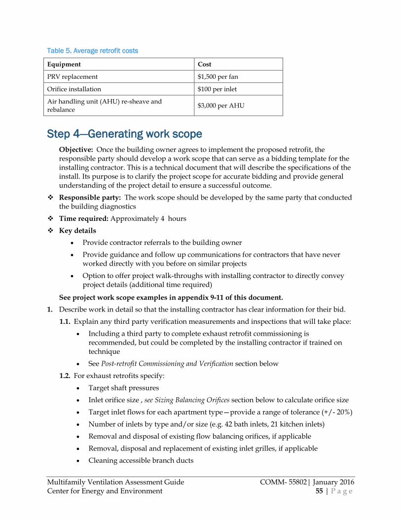
Multifamily Ventilation Assessment Guide COMM- 55802| January 2016 Center for Energy and Environment 55 | P a g e
Table 5. Average retrofit costs
Equipment Cost
PRV replacement $1,500 per fan
Orifice installation $100 per inlet
Air handling unit (AHU) re-sheave and rebalance $3,000 per AHU
Step 4—Generating work scope Objective: Once the building owner agrees to implement the proposed retrofit, the responsible party should develop a work scope that can serve as a bidding template for the installing contractor. This is a technical document that will describe the specifications of the install. Its purpose is to clarify the project scope for accurate bidding and provide general understanding of the project detail to ensure a successful outcome.
Responsible party: The work scope should be developed by the same party that conducted the building diagnostics
Time required: Approximately 4 hours Key details
• Provide contractor referrals to the building owner • Provide guidance and follow up communications for contractors that have never
worked directly with you before on similar projects • Option to offer project walk-throughs with installing contractor to directly convey
project details (additional time required)
See project work scope examples in appendix 9-11 of this document. 1. Describe work in detail so that the installing contractor has clear information for their bid.
1.1. Explain any third party verification measurements and inspections that will take place: • Including a third party to complete exhaust retrofit commissioning is
recommended, but could be completed by the installing contractor if trained on technique
• See Post-retrofit Commissioning and Verification section below 1.2. For exhaust retrofits specify:
• Target shaft pressures • Inlet orifice size , see Sizing Balancing Orifices section below to calculate orifice size • Target inlet flows for each apartment type—provide a range of tolerance (+/- 20%) • Number of inlets by type and/or size (e.g. 42 bath inlets, 21 kitchen inlets) • Removal and disposal of existing flow balancing orifices, if applicable • Removal, disposal and replacement of existing inlet grilles, if applicable • Cleaning accessible branch ducts
Multifamily Ventilation Assessment Guide COMM- 55802| January 2016 Center for Energy and Environment 56 | P a g e
• Sealing ducts where accessible from the inlets and roof curb • Replacement rooftop fan sizes and models, as possible • Post-retrofit flow measurement that the contractor is required to conduct and
minimum accuracy of measurement device (recommend +/- 10%):
At minimum have contractor verify that flow on the 1st floor of each shaft is not more than 15% below the flow target (85% of target) after the fan speed is adjusted to produce the target shaft pressure (the contractor should make fan adjustments if necessary to achieve 1st floor target flow)
1.3. For corridor retrofits specify: • Coil or screen cleaning before adjustment, if applicable • Target fan speed and/or flow rate • Flow distribution balancing and tolerance (+/- 20%) • Any access logistics (e.g. ladder needed for 2nd story intake grille cleaning) • Request submission of Test and Balance report to building owner upon completion
of work 1.4. For trash chute system retrofits specify:
• Trash room air sealing details • Rooftop termination adjustments (e.g. adjust trash chute roof cap to provide a
maximum of 75 in² open area to limit chute exhaust) • Post-retrofit measurements that the contractor is required to conduct • If enclosing the trash chute outlet around the compactor:
• Enclosure type (sheet metal or durable membrane) • Access panel for chute inspection • Gasket at joints (where dumpster meets compactor and chute enclosure
meets compactor)
Sizing Balancing Orifices In order to determine the size of the balancing orifice, first determine the exhaust shaft target operating pressure and your desired inlet flow. Remember that airflow is dependent upon the area of the orifice and the pressure difference across the orifice.
The simplest method for determining the target shaft pressure and resulting orifice size is by using either Table 6 or Table 7 based on the building’s height (number of stories) and common inlet airflows (20 for baths, 25 for kitchens, and 35 as a commonly substituted airflow for the kitchen or bath inlet to meet the “living area” ventilation requirement). Table 6 can be used if orifices will be custom stamped into a sheet metal adapter plate. Table 7 specifies prefabricated metal washers that can be fastened to a sheet metal adapter plate in the duct. Depending on the building and the contractor, providing a washer versus a custom stamped adapter plate may prove to be more cost effective. It is best to provide both options in the work scope. If the exhaust ventilation targets for the building are not listed in Table 6 or Table 7, the following

Multifamily Ventilation Assessment Guide COMM- 55802| January 2016 Center for Energy and Environment 57 | P a g e
sections provide guidance on determining the shaft pressure and calculating the orifice size based on the target shaft pressure and desired inlet flow.
Table 6. Custom orifice sizes for common apartment inlet flows
# Stories
Shaft Pressure Orifice Area (sq in) Round Orifice Diameter (in)
(Pa) Bath (20cfm)
Kitchen (25cfm) 35cfm Bath
(20cfm) Kitchen (25cfm) 35cfm
1 to 5 25 3.33 4.17 5.83 2.06 2.30 2.73
6 to 10 35 2.97 3.52 4.93 1.94 2.12 2.51
10+ 45 2.62 3.27 4.35 1.82 2.04 2.35
Table 7. Prefabricated washer sizes, used as orifices for common apartment inlet flows
# Stories Bathroom (20 cfm) Kitchen (25 cfm) 35 cfm
Orifice* Shaft Press
(Pa) Orifice Shaft Press
(Pa) Orifice Shaft Press
(Pa)
1 to 5 1.5" 32 2" 20 2" 38
6 to 10 1.5" 32 1.5" 50 2" 38
10+ 1.25" 48 1.5" 50 2" 38
*Refers to nominal washer size; actual washer orifice size is as follows: nominal 2” = actual 2.45”, nominal 1.5”= actual 1.97”, nominal 1.25”= actual 1.73”
Determining the target shaft pressure
Table 8 lists design shaft pressures for buildings based upon height (number of stories). Note that the design pressures are much lower than the HVAC industry convention for shaft pressure in exhaust systems. This is partly because starting with a low design shaft pressure allows for more flow adjustment range during commissioning. Further, targeting a lower operating pressure generally reduces fan power use and minimizes duct leakage. Though the shaft pressure may need adjustment up or down to achieve the target inlet flows throughout the building, the shaft design pressures provide a starting point from which to calculate orifice size.
Table 8. Shaft design pressures
Number of Stories Pressure
1 - 5 stories ≥25Pa
6 - 10 stories ≥35Pa
10+ stories ≥45Pa

Multifamily Ventilation Assessment Guide COMM- 55802| January 2016 Center for Energy and Environment 58 | P a g e
Calculating orifice size based on design shaft pressure
To determine the size of the orifice for a desired airflow to an exhaust inlet, use the below equation:
𝑂𝑂𝑂𝑂𝑎𝑎𝑜𝑜𝑎𝑎𝑜𝑜𝑟𝑟 𝑎𝑎𝑂𝑂𝑟𝑟𝑎𝑎 (𝑎𝑎𝑟𝑟2) =𝐷𝐷𝑟𝑟𝑠𝑠𝑎𝑎𝑂𝑂𝑟𝑟𝑂𝑂 𝑂𝑂𝑂𝑂𝑎𝑎𝑜𝑜𝑎𝑎𝑜𝑜𝑟𝑟 𝑜𝑜𝑠𝑠𝑂𝑂𝑓𝑓, 𝑜𝑜𝑜𝑜𝑐𝑐
1.14�(𝑠𝑠𝑂𝑂𝑟𝑟𝑠𝑠𝑠𝑠𝑂𝑂𝑂𝑂𝑟𝑟 𝑎𝑎𝑜𝑜𝑂𝑂𝑂𝑂𝑠𝑠𝑠𝑠 𝑂𝑂𝑂𝑂𝑎𝑎𝑜𝑜𝑎𝑎𝑜𝑜𝑟𝑟, 𝑃𝑃𝑎𝑎)∗
Where:
• The orifice is round or rectangular, sharp-sided and installed perpendicular to direction of air flow
• A multiplier of 1.14 is used when the orifice diameter ≤ ½ the diameter of the duct it is in (see diagram below) and a multiplier of 1.2 is used when the orifice diameter is greater than ½ the duct diameter
• Pressure across orifice in Pascals is the shaft pressure (taken from Table 8 above) with reference to the inside
Example (7 story building):
Shaft pressure (pressure across the orifice) = 35Pa (0.14 in wc)
Desired flow rate = 20 cfm (bathroom)
Orifice area = 20/(1.14*(35)1/2 = 2.97 sq in
Orifice diameter = 2*(2.97/3.14)1/2 = 1.94 in
The flow through an orifice is equal to a constant multiplied by the orifice area and the square root of the orifice pressure difference divided by the air density. The constant varies up to 10% depending on the diameter of the orifice relative to the duct. For example, for orifice diameters that range from 1.37” to 2.45” installed in a 4”x6” duct the multiplier varies from 1.12 to 1.21 (Figure 27).
Determining orifice multiplier.
A ≤ ½ B: multiplier = 1.14
A > B: multiplier = 1.21

Multifamily Ventilation Assessment Guide COMM- 55802| January 2016 Center for Energy and Environment 59 | P a g e
Figure 27. Orifice pressure difference vs. Flow rate through the orifice for 4”x6” duct
It is not necessary to provide different sized orifices from top to bottom of the building. The shaft pressure does not change significantly from the bottom to the top of the building as long as there are not significant leaks or restrictions in the shaft. Also, the relative change in the orifice flow is about half that of a change in the pressure. The shaft pressure can change by 20% and only produce a 10% change in flow. The following is an example of this:
• Bathroom inlets designed for 20cfm for a 7 story building
• Orifice design with shaft pressure of 32Pa and orifice diameter = 1.97”
• Fan adjusted for shaft pressure of 35Pa at top floor with pressure 9% above target and flow rate only 5% above target (flow = 20.9cfm = 3.54*(35)1/2)
• Pressure at lower floors can drop to 26Pa (19% below target) and flow rate will still be within 10% of target (flow = 18.1cfm = 3.54*(26)1/2)
Step 5—Post-retrofit Commissioning and Verification Objective: Ensure installation was completed as specified and check that ventilation
airflow rates are within the specified tolerance of targets. Responsible party: A third party professional (independent from installing contractor) is
recommended for exhaust retrofits. An installing contractor who is Associated Air Balance Council or National Environmental Balancing Bureau certified is acceptable for hallway ventilation systems verification/commissioning. The installing contractor can submit pictures for trash chute verification.
Equipment • Tools listed on Ventilation Assessment tool list (Appendix 3)

Multifamily Ventilation Assessment Guide COMM- 55802| January 2016 Center for Energy and Environment 60 | P a g e
• Target airflows for ventilation systems • Equipment associated with selected airflow measurement methods • Rebate application (contact local energy utility)
Time required: 4 hours Key details
• Include site management, building owner and installer in all cross-communications regarding verification findings and adjustments required.
Commissioning a central exhaust system 1. Verify a representative sample of exhaust shafts
After all work is complete, verify a sample of shafts that includes no less than two of each type (e.g. two kitchen and two bath shafts). Flow rate measurements should use one of the diagnostic methods listed in the Airflow Measurement Methods section of this document. 1.1. Check a sample 3-5 of inlet orifice installations.
• Make sure duct has been effectively sealed to the wall or ceiling finish. • Make sure orifice is the correct size and has been mechanically fastened and sealed
to the duct inlet, oriented perpendicular to the inlet airflow. • If any are not installed or sealed correctly, call contractor to repair
• Inspect 3-5 more, repeat if necessary 1.2. Verify correct make/model fan installed. 1.3. Measure the shaft pressure at fan inlet or top floor inlet or duct and adjust fan flow as
necessary to meet desired shaft pressure and measure inlet flow at top floor. • Adjust fan flow to meet target flow at that inlet, if necessary.
1.4. Confirm that the inlet flows at the bottom floor of the shaft are within an acceptable range (not less than 85% of target flow). • Depending on the shaft flow restriction and leakage, it may be necessary to increase
the flow rate at the inlet closest to the fan to higher than desired level in order to provide an acceptable flow rate for the inlet furthest from the fan.
• Alternatively, additional work would be required to increase the size of the orifice for the inlets further from the fan, decrease the size of the orifices closest to the fan, and/or address the shaft restriction/leakage issues. This is generally cost-prohibitive.
1.5. Record the “commissioned shaft pressure” after making final adjustments and note the measurement location for that shaft type.
1.6. After making final adjustments to the fan to achieve target inlet flow rates, measure the total PRV flow using a diagnostic method described in the “Airflow Measurement Methods” section of the document. • If measured PRV flow at or below 120% of target flow rate, commissioning is
complete for that shaft type.

Multifamily Ventilation Assessment Guide COMM- 55802| January 2016 Center for Energy and Environment 61 | P a g e
• All other fans of that shaft type may be adjusted to a similar shaft pressure using a similar pressure measurement location as recorded in 1.5 above.
• For any shaft where the measured PRV flow is more than 20% above the target flow rate for the shaft, recommend to investigate duct sealing opportunities and complete steps 1.3-1.5 above for two additional shafts of similar type. • If the two additional shaft PRV flows were measured at or below 120% of target
flow rate, commissioning is complete for that shaft type.
• All other fans of that shaft type should be adjusted to match the commissioned shaft pressure using a similar pressure measurement location as recorded in 1.5 above.
• Recommend to investigate duct sealing opportunities on the one shaft that exceeded target flow by 120%.
• If either of the additional shaft PRV flows are more than 20% above the target flow rate for the shaft, recommend to investigate duct sealing opportunities for all similar shaft types.
Duct sealing options: • Seal any accessible ducts (in roof cavities, mechanical rooms, etc.). • Aeroseal duct sealant can be injected into the duct to seal up to ½” gaps in non-
accessible areas
The following is an example exhaust commissioning procedure:
Measure one shaft of each unique type following the steps below. Note that additional shafts of similar type may be required to be tested if they do not meet design targets by 20%.
1. Measure the shaft pressure at the {specify location: fan inlet or top floor inlet or duct} and adjust fan flow as necessary to meet desired shaft pressure.
2. Measure the inlet flow rate for the upper floor bathroom inlet. The acceptable flow range is 17 to 23 cfm. If necessary, adjust the fan flow rate to achieve an inlet flow rate between 17 to 23 cfm.
3. If the fan flow rate was reduced by step two (2), measure the inlet flow rate for the lower floor bathroom. The minimum acceptable flow rate is 17 cfm. If necessary, increase the fan flow rate to achieve an inlet flow of at least 17 cfm.
4. Measure total PRV flow after all fan adjustments were made. Confirm PRV flow does not exceed the target flow for the shaft by more than 20%. • If PRV flow exceeds target by more than 20%, complete steps 1-5 for two additional
similar shaft types. • If the 2 additional shaft PRV flows were measured at or below 120% of target
flow rate, commissioning is complete for that shaft type. • Recommend to investigate duct sealing opportunities on the one shaft that
exceeds target. • If either of the additional shaft PRV flows are more than 20% above the
target flow rate for the shaft, recommend the building owner investigate duct sealing opportunities for all similar shaft types.
Multifamily Ventilation Assessment Guide COMM- 55802| January 2016 Center for Energy and Environment 62 | P a g e
• If PRV flow is at or below 120% of flow target for shaft, commissioning is complete for this shaft. • Adjust remaining shafts to match the commissioned shaft pressure found in
steps 1-4 for similar shaft types.
Verifying a central supply system retrofit 1. Supply re-sheave or VFD adjustment
1.1. Verify total outdoor airflow intake using a method described in the Airflow Measurement Methods section of this document or confirm the measurement on the Test and Balance report provided by contractor.
• Flows should be within +/- 20% of target flow rate for re-sheave retrofits and +/- 10% for VFD systems.
1.2. Review flow distribution flow balancing report from the Test and Balance contractor to ensure that the air flow rate to each floor was within +/- 20% of target for the floor.
Verifying trash chute system operation 1. Trash chute inspections. After a ventilation retrofit, it is beneficial to check the operation of
the trash chute regardless of whether any changes were made directly to the trash chute system. 1.1. Inspect that trash room does not have major air leaks to the building.
1.1.1. Make sure trash room doors are not propped open. 1.1.2. If trash chute outlet was enclosed as a part of the work scope, make sure
enclosure meets project specifications. 1.2. Inspect that the chute cap at the rooftop is intact and is installed with no more than 75
inches² of open area for exhaust flow restriction.
1.3. Use chemical smoke to confirm air is being drawn up the trash chute on the bottom floor. If air does not draw up check for chute blockage and if there is none, adjust roof termination cap to provide more open area and recheck chute with smoke at bottom. Repeat if necessary.
Multifamily Ventilation Assessment Guide COMM- 55802| January 2016 Center for Energy and Environment 63 | P a g e
Appendices 1. Multifamily Ventilation Assessment: Phone Survey form 2. Multifamily Ventilation Assessment: Building Screening form 3. Ventilation Assessment tool list 4. Resident Notification form 5. Screening decision trees:
5.1. Trash Chute Decision Tree 5.2. Central Exhaust Ventilation Decision Tree 5.3. Corridor ventilation Decision Tree
6. Ventilation Findings report (example) 7. Multifamily Ventilation Assessment: Building Diagnostic form 8. Ventilation Assessment report (example) 9. Project work scope—exhaust system (example) 10. Project work scope—supply/corridor system (example) 11. Project work scope—trash chute (example)
Appendix 1
Multifamily Ventilation Assessment: Phone
Survey Form

f ield form_Phone Survey.docx Last printed 5/12/2015 5:14:00 PM
Phone Survey –Multifamily Ventilation Assessment
Building Name and Address: ________________________________________________________________________
Date: _____________ Time: ___________ Technician: ______________________________________________
BUILDING GENERAL
General
Year built: _________ (Year of major rehab. (if any): __________)
# Stories: _________
# Total units: _________
Apartment f loor plan available? (Framing plans)
Mechanical system plans available?
Will email Provided hardcopy Not avail. DK
Will email Provided hardcopy Not avail. DK
Building staff Name: Title:
Email: Phone:
HALLWAY VENTILATION SYSTEM
Is there a hallw ay ventilation system? Yes No DK (If NO or DK, skip rest of section)
Does system run continuous (24/7) or intermittent? DK
Location of hallw ay/corridor air handler
Rooftop Wall
Indoors: _______________________________
DK
Outdoor air intake location Rooftop Penthouse Exterior w all (ladder access?) DK
Recent maintenance or repair? No DK Yes:
Any problems, concerns or complaints about hallw ay
ventilation? No Yes:
APARTMENT EXHAUST
Is there an apartment central exhaust ventilation
system? (i.e. Fans on roof or in a penthouse pulling air out of apartments?)
Yes No DK (If NO or DK, skip rest of section)
How many total exhaust fans?
Exhaust fan location Rooftop Penthouse Attic DK Other:
Apartment central exhaust inlet location:
Kitchen exhaust hood Kitchen w all or ceiling inlet
Bathroom DK Other:
Occupant odor or moisture complaints? No Yes:
Recent maintenance or repair? No DK Yes:
Other concerns or complaints? No Yes:
TRASH CHUTE
Is there a trash chute? Yes No DK (If NO or DK, skip next question)
Odor or other complaints? No DK Yes: _______________________________
OPERATOR QUESTIONS
Adjustments or modif ications to system in past?
Moisture, humidity or odor problems?
Any other problems w ith ventilation? Resident
complaints?

Appendix 2
Multifamily Ventilation Assessment: Building
Ventilation Screening Visit Form
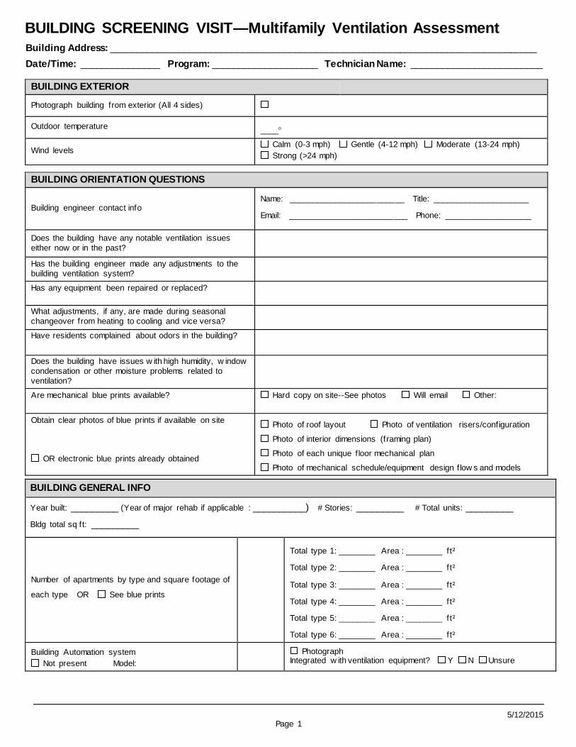
5/12/2015 Page 1
BUILDING SCREENING VISIT—Multifamily Ventilation Assessment
Building Address: _________________________________________________________________________________
Date/Time: _______________ Program: ____________________ Technician Name: _________________________
BUILDING EXTERIOR
Photograph building from exterior (All 4 sides)
Outdoor temperature ____
Wind levels Calm (0-3 mph) Gentle (4-12 mph) Moderate (13-24 mph)
Strong (>24 mph)
BUILDING ORIENTATION QUESTIONS
Building engineer contact info Name: _________________________ Title: _____________________
Email: __________________________ Phone: ___________________
Does the building have any notable ventilation issues
either now or in the past?
Has the building engineer made any adjustments to the
building ventilation system?
Has any equipment been repaired or replaced?
What adjustments, if any, are made during seasonal
changeover from heating to cooling and vice versa?
Have residents complained about odors in the building?
Does the building have issues w ith high humidity, w indow
condensation or other moisture problems related to
ventilation?
Are mechanical blue prints available? Hard copy on site--See photos Will email Other:
Obtain clear photos of blue prints if available on site
OR electronic blue prints already obtained
Photo of roof layout Photo of ventilation risers/configuration
Photo of interior dimensions (framing plan)
Photo of each unique f loor mechanical plan
Photo of mechanical schedule/equipment design f low s and models
BUILDING GENERAL INFO
Year built: _________ (Year of major rehab if applicable : __________) # Stories: _________ # Total units: _________
Bldg total sq ft: _________
Number of apartments by type and square footage of
each type OR See blue prints
Total type 1: ________ Area : ________ ft²
Total type 2: ________ Area : ________ ft²
Total type 3: ________ Area : ________ ft²
Total type 4: ________ Area : ________ ft²
Total type 5: ________ Area : ________ ft²
Total type 6: ________ Area : ________ ft²
Building Automation system
Not present Model:
Photograph Integrated w ith ventilation equipment? Y N Unsure

Building Screening Visit: Multifamily Ventilation Assessment Building Address:
Page 2 5/12/2015
APARTMENT CENTRAL VENTILATION FLOW N/A
Apt # Floor #
bdrms
#
baths
Apt
Ft²
Inlet
location
Damper position
(open or closed)
Clogged / Dusty?
Condensation or
moisture (Y/N)
REQ’D
CFM
MEAS’D
CFM Static Prsr
EXCESS CFM
1
2
3
4
5
6
7
8
9
1
0
11
12
1
3
1
4
15
16
1
7
1
8
19
20
2
1
2
2
23
24
2
5
2
6
27
28

Building Screening Visit: Multifamily Ventilation Assessment Building Address:
Page 3 5/12/2015
EXHAUST INLET NOTES
CORRIDOR VENTILATION 1 CORRIDOR VENTILATION 2 CORRIDOR VENTILATION 3
Photos
General system photo
Outdoor air intake Fan Nameplate
Motor nameplate
Photos
General system photo
Outdoor air intake Fan Nameplate
Motor nameplate
Photos
General system photo
Outdoor air intake Fan Nameplate
Motor nameplate
Type of conditioning for air handler :
Heat:________________________Cool: _______________________
Type of conditioning for air handler :
Heat:________________________Cool: _______________________
Type of conditioning for air handler :
Heat:_______________________Cool: ______________________
Outdoor air damper position:
Open Closed (do not proceed)
Outdoor air damper position:
Open Closed (do not proceed)
Outdoor air damper position:
Open Closed (do not proceed)
Hours of operation
Runs continuous 24/7
Runs intermittent – hours/day: ________
Hours of operation
Runs continuous 24/7
Runs intermittent – hours/day: ________
Hours of operation
Runs continuous 24/7
Runs intermittent – hours/day:
________
Description of area served Description of area served Description of area served
Measured cfm of outdoor airf low : ________ Measured cfm of outdoor airf low : ________ Measured cfm of outdoor airf low :
________
ROOFTOP: TRASH CHUTE EXHAUST TERMINATION Open exhaust area: < or = to 75 inches² > 75 inches²
NOTES:
ROOFTOP: CENTRAL EXHAUST FANS
Total number rooftop exhaust fans: ____
General photo of roof layout General photo of each fan
Nameplate photo of each Nameplate not visible
Exhaust fan types Direct Drive PRVs:____ # Speed controls: ____
Belt Driven PRVs: ____
Shaft condition below PRV Intact or discontinuous

Building Screening Visit: Multifamily Ventilation Assessment Building Address:
Page 4 5/12/2015
ROOFTOP FAN LAYOUT

Building Screening Visit: Multifamily Ventilation Assessment Building Address:
Page 5 5/12/2015
OPTIONAL: PRV FLOW MEASUREMENT
Tag Model
Required flow
for inlets
serv ed
Curb dimensions
(LxWxH) Cap dimensions Measured
flow (cfm) Flow/unit
1
2
3
4
5
6
7
8
9
10
11
12
13
14
15
16
17
18

Building Screening Visit: Multifamily Ventilation Assessment Building Address:
Page 6 5/12/2015
Model
Required flow for
inlets serv ed
Curb
dimensions (LxWxH) Cap dimensions Measured flow (cfm) Flow/unit Tag
19
20
21
22
23
24
25
26
27
28
29
30
31
32
33
34
35
36
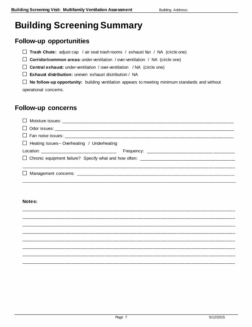
Building Screening Visit: Multifamily Ventilation Assessment Building Address:
Page 7 5/12/2015
Building Screening Summary Follow-up opportunities
Trash Chute: adjust cap / air seal trash rooms / exhaust fan / NA (circle one)
Corridor/common areas: under-ventilation / over-ventilation / NA (circle one)
Central exhaust: under-ventilation / over-ventilation / NA (circle one)
Exhaust distribution: uneven exhaust distribution / NA
No follow-up opportunity: building ventilation appears to meeting minimum standards and without
operational concerns.
Follow-up concerns
Moisture issues: ________________________________________________________________________
Odor issues: ___________________________________________________________________________
Fan noise issues: _______________________________________________________________________
Heating issues-- Overheating / Underheating
Location: ________________________________ Frequency: ____________________________ _________
Chronic equipment failure? Specify what and how often: ________________________________________
_________________________________________________________________________________________
Management concerns: _____________________________________________________________________________
________________________________________________________________________________________________________
Notes:
_________________________________________________________________________________________
_________________________________________________________________________________________
_________________________________________________________________________________________
_________________________________________________________________________________________
_________________________________________________________________________________________
_________________________________________________________________________________________
_________________________________________________________________________________________
_________________________________________________________________________________________
Appendix 3
Inspection Tool List

Inspection tool list
Hard hat
Safety vest
Safety Harness / rope
Cart (s) or dolly
Ladder (4’) or (2’)
Ladder--extension
Tape measure
Drill
Drill bits (punching vent holes)—long drill bits
Driver bits
Utility knife
Camera w/ charged battery
Flashlight
Smoke
Pressure probes/static probe
Duct Mask
Masking tape
Cold weather tape
Measuring wheel
Laser measure
Flow meter box
Temperature probe
Snow shovel
Extra batteries (AA, AAA, etc)
Extension cords
Computer hook-ups (cords)?
Hoses (100’ for inside reference)
Hose Connectors: tees, couplings
2- DG 700
Awl
Silicone
Long drill bits
Sled
Kneepads
Clipboard
Waterproof/windproof clipboard cover
Pencils
AHU’s
Trueflow plates for 3600 cfm
Cardboard to block off rest of filter rack
Cold weather tape
Blower door
Blower door rings
Blower door control
TSI or Testo
Dranetz to measure power
PRVs
Cardboard capture cube
Trueflow plates: 2-#14, 2-#20
Tachometer
Duct mask
Inlets
Flow blaster,
Flow blaster control (CHARGE BATTERY PACK!)
Duct blaster fan w/ handles
Duct blaster rings (2,3)
Duct mask to block off grilles
Drill
Range hood adapter
Appendix 4
Resident Notification Form

Notice to Resident of Apartment Entry
On the date and time specified
below, staff will be entering your
apartment to complete the
following tasks:
Measure airflow on ventilation
registers
Inspect ventilation duct
Measure square footage
Building: ______________________________________________________
Date of apartment entry: ________________________________________
Time of apartment entry: Between _____________ and ______________
Special Instructions
Secure all pets in a kennel or bedroom.
For your pets’ and our staff safety, please ensure all
pets are in a kennel or bedroom on the day of
apartment entry.
We will require 10-25 minutes to finish
all work. Please allow brief access to all rooms
including bathroom(s).
This building is becoming more
energy efficient! Energy professionals from Center for Energy and Environment will be conducting tests in your apartment building on the date l isted below.
Center for Energy and Environment is a local non-profit that provides a range of practical and cost-effective programs to help MN residents, businesses, and governments reduce energy waste and save money. Check out their website at www.mncee.org!
Questions or concerns? If you have any concerns or special considerations regarding this process, please email: [email protected]

Appendix 5
Screening Decision Trees

Central Exhaust Ventilation definition. Powered fans ducted to provide exhaust ventilation to multiple apartment units.
A. Measure inlet flowsMeasure an inlet flow near the top and
bottom of every shaft
OR
Measure 25% or 4 inlets (whichever is a
larger number) on at least 2 of each
unique type of shaft in the building
(include the top and bottom inlet of each
shaft measured). Follow the procedure
in the “Building Screen Visit” section of
the Multifamily Ventilation Assessment &
Retrofit Guide to determine Threshold
CFM Excess. Include the nearest and
furthest inlets from the fan in your inlet
measurements (top floor and bottom
floor).
If any inlet measured is clogged, shut, or
the flow is blocked, do not include that
inlet in your threshold CFM excess
calculation and measure another nearby
inlet that has measureable airflow. If any
inlet has very low flow, measure static
pressure of the shaft by inserting a
pressure probe past the flow balancing
device behind the inlet register (if flow
balancing device is present).
Central exhaust ventilation screening
If average unit flows are
neither more than 20%
below code, nor above
threshold CFM excess
1 - 1
There is evidence of low flow or distribution inequities which may
effect indoor air quality. Recommend that an HVAC professional
investigate options for balancing flow to restore code required
ventilation to all units.
Any measured flows are
higher than the threshold
airflow amount
B.1. Measure outlet flow *
Measure airflow on at least 2 of each
type of exhaust fans (measure all if
possible). Use a recommended
method from the “Airflow Measurement
Methods” section of the Multifamily
Ventilation Assessment & Retrofit
Guide to quantify the total conditioned
exhaust leaving the building. Calculate
the threshold airflow amount using the
equation below to assist in determining
your recommendation.
Flow is 20% or more
below code requirement
for the units served
Average of measured flows
do not exceed the
threshold airflow amount
but are not more than 20%
below code requirement for
the units served
“High PRV flows”
Significant energy savings is available from modifying or
retrofitting this system. Recommend advanced diagnostics
to identify retrofit solution and quantify energy savings.
Proceed to step B.2.
“Normal PRV flows”
Proceed to step B.2.
“Low PRV flows”
Total exhaust ventilation airflow is below recommended
levels by a significant margin. Recommend to have
HVAC professional investigate options for adding
ventilation to the building for improved air quality.
Proceed to step B.2.
No flow modifications or balancing orifices recommended.
Clean inlet grilles and any balancing orifices or dampers on
apartment turns to maintain airflow.
If average unit flows are
at or above Threshold
CFM excess
If average unit flows are
more than 20% below
code requirement
Significant energy savings is available by reducing overall
exhaust flow. Recommend that an HVAC professional
investigate reducing overall exhaust flows. Paybacks for this
upgrade may range from 2-7 years.
Instructions. Complete A OR B depending upon which is more efficient given building access, configuration. Use the
process described in the Multifamily Ventilation Assessment and Retrofit Guide and utilize findings and decision tree below to
determine recommendations.
Calculating the threshold
airflow amount
Threshold airflow =
(Code required CFM)+(12 CFM per
inlet served by fan)+100
Example: One fan serves a shaft with
10 inlets on it. The code requirement
for the bathroom is 25cfm:
(25 cfmx10 inlets)+(12cfm x 10
inlets)+100 = 470
Threshold CFM excess per inlet
based on number of stories
4-6 stories = code req’ment + 25 cfm
7-14 stories = code req’ment + 20 cfm
15+ stories = code req’ment + 15 cfm
B.2. Measure a sample of inletsMeasure airflow at the top and bottom of at least 2 shafts of
similar configuration to test for distribution inequities that
may be affecting ventilation performance.
Inlet flow is within 20%
of code requirement
Inlet flow is 20% or
more above or below of
code requirement
There is evidence distribution inequities which may
effect indoor air quality. Recommend that an HVAC
professional investigate options for balancing flow to
restore code required ventilation to all units.
No evidence of distribution inequities. If
retrofitting or modifying the system, have inlets
checked for balanced distribution.
OR
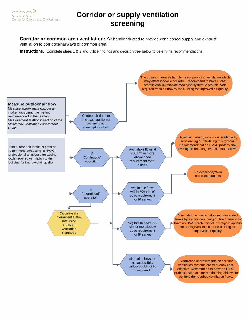
Measure outdoor air flowMeasure approximate outdoor air
intake flows using the method
recommended in the “Airflow
Measurement Methods” section of the
Multifamily Ventilation Assessment
Guide.
Corridor or common area ventilation: Air handler ducted to provide conditioned supply and exhaust
ventilation to corridors/hallways or common area
Avg intake flows at
700 cfm or more
above code
requirement for ft²
served
Avg intake flows
within 700 cfm of
code requirement
for ft² served
Avg intake flows 700
cfm or more below
code requirement
for ft² served
Ventilation airflow is below recommended
levels by a significant margin. Recommend to
have an HVAC professional investigate options
for adding ventilation to the building for
improved air quality.
No exhaust system
recommendations
Outdoor air damper
in closed position or
system is not
running/turned off
The common area air handler is not providing ventilation which
may affect indoor air quality. Recommend to have HVAC
professional investigate modifying system to provide code
required fresh air flow to the building for improved air quality.
If no outdoor air intake is present
recommend contacting a HVAC
professional to investigate adding
code required ventilation to the
building for improved air quality
Corridor or supply ventilation
screening
If
“Continuous”
operation
If
“Intermittent”
operation
Significant energy savings is available by
rebalancing or retrofitting this system.
Recommend that an HVAC professional
investigate reducing overall exhaust flows.
Calculate the
intermittent airflow
rate using
ASHRAE
ventilation
standards
Instructions. Complete steps 1 & 2 and utilize findings and decision tree below to determine recommendations.
Air intake flows are
not accessible/
airflow could not be
measured
Ventilation improvements on corridor
ventilation systems are frequently cost-
effective. Recommend to have an HVAC
professional evaluate rebalancing airflows to
achieve the required ventilation flows.
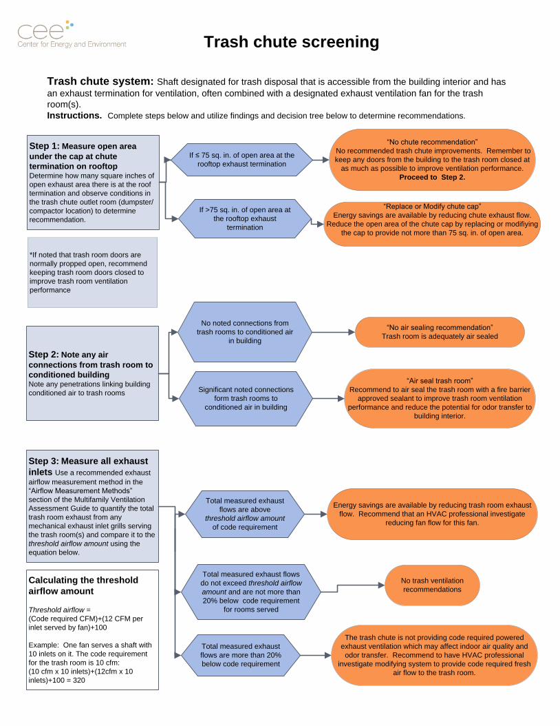
Trash chute system: Shaft designated for trash disposal that is accessible from the building interior and has
an exhaust termination for ventilation, often combined with a designated exhaust ventilation fan for the trash
room(s).
Trash chute screening
Step 1: Measure open area
under the cap at chute
termination on rooftopDetermine how many square inches of
open exhaust area there is at the roof
termination and observe conditions in
the trash chute outlet room (dumpster/
compactor location) to determine
recommendation.
*If noted that trash room doors are
normally propped open, recommend
keeping trash room doors closed to
improve trash room ventilation
performance
If ≤ 75 sq. in. of open area at the
rooftop exhaust termination
“No chute recommendation”
No recommended trash chute improvements. Remember to
keep any doors from the building to the trash room closed at
as much as possible to improve ventilation performance.
Proceed to Step 2.
“Replace or Modify chute cap”
Energy savings are available by reducing chute exhaust flow.
Reduce the open area of the chute cap by replacing or modifiying
the cap to provide not more than 75 sq. in. of open area.
Step 3: Measure all exhaust
inlets Use a recommended exhaust
airflow measurement method in the
“Airflow Measurement Methods”
section of the Multifamily Ventilation
Assessment Guide to quantify the total
trash room exhaust from any
mechanical exhaust inlet grills serving
the trash room(s) and compare it to the
threshold airflow amount using the
equation below.
Total measured exhaust flows
do not exceed threshold airflow
amount and are not more than
20% below code requirement
for rooms served
The trash chute is not providing code required powered
exhaust ventilation which may affect indoor air quality and
odor transfer. Recommend to have HVAC professional
investigate modifying system to provide code required fresh
air flow to the trash room.
No trash ventilation
recommendations
Total measured exhaust
flows are above
threshold airflow amount
of code requirement
Total measured exhaust
flows are more than 20%
below code requirement
Energy savings are available by reducing trash room exhaust
flow. Recommend that an HVAC professional investigate
reducing fan flow for this fan.
Instructions. Complete steps below and utilize findings and decision tree below to determine recommendations.
If >75 sq. in. of open area at
the rooftop exhaust
termination
No noted connections from
trash rooms to conditioned air
in building
“Air seal trash room”
Recommend to air seal the trash room with a fire barrier
approved sealant to improve trash room ventilation
performance and reduce the potential for odor transfer to
building interior.
Significant noted connections
form trash rooms to
conditioned air in building
Step 2: Note any air
connections from trash room to
conditioned buildingNote any penetrations linking building
conditioned air to trash rooms
“No air sealing recommendation”
Trash room is adequately air sealed
Calculating the threshold
airflow amount
Threshold airflow =
(Code required CFM)+(12 CFM per
inlet served by fan)+100
Example: One fan serves a shaft with
10 inlets on it. The code requirement
for the trash room is 10 cfm:
(10 cfm x 10 inlets)+(12cfm x 10
inlets)+100 = 320
Appendix 6
Example of Ventilation Findings Report
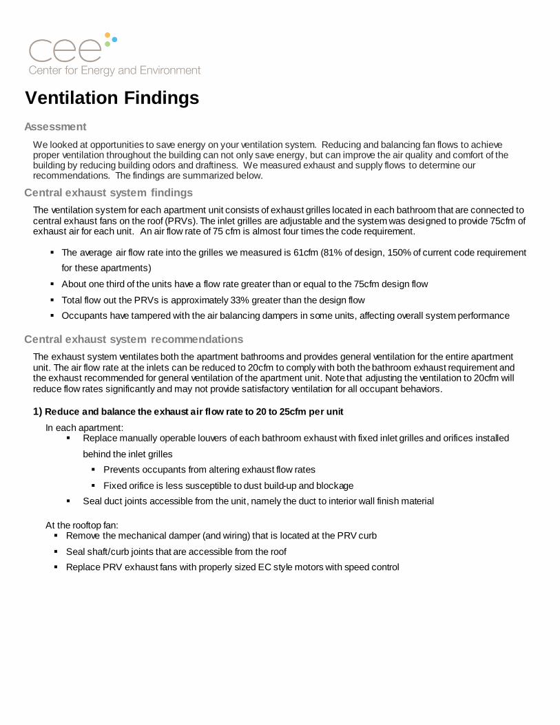
Ventilation Findings
Assessment
We looked at opportunities to save energy on your ventilation system. Reducing and balancing fan flows to achieve proper ventilation throughout the building can not only save energy, but can improve the air quality and comfort of the building by reducing building odors and draftiness. We measured exhaust and supply flows to determine our recommendations. The findings are summarized below.
Central exhaust system findings
The ventilation system for each apartment unit consists of exhaust grilles located in each bathroom that are connected to central exhaust fans on the roof (PRVs). The inlet grilles are adjustable and the system was designed to provide 75cfm of exhaust air for each unit. An air flow rate of 75 cfm is almost four times the code requirement.
The average air flow rate into the grilles we measured is 61cfm (81% of design, 150% of current code requirement
for these apartments)
About one third of the units have a flow rate greater than or equal to the 75cfm design flow
Total flow out the PRVs is approximately 33% greater than the design flow
Occupants have tampered with the air balancing dampers in some units, affecting overall system performance
Central exhaust system recommendations
The exhaust system ventilates both the apartment bathrooms and provides general ventilation for the entire apartment unit. The air flow rate at the inlets can be reduced to 20cfm to comply with both the bathroom exhaust requirement and the exhaust recommended for general ventilation of the apartment unit. Note that adjusting the ventilation to 20cfm will reduce flow rates significantly and may not provide satisfactory ventilation for all occupant behaviors. 1) Reduce and balance the exhaust air flow rate to 20 to 25cfm per unit
In each apartment: Replace manually operable louvers of each bathroom exhaust with fixed inlet grilles and orifices installed
behind the inlet grilles
Prevents occupants from altering exhaust flow rates
Fixed orifice is less susceptible to dust build-up and blockage
Seal duct joints accessible from the unit, namely the duct to interior wall finish material
At the rooftop fan: Remove the mechanical damper (and wiring) that is located at the PRV curb
Seal shaft/curb joints that are accessible from the roof
Replace PRV exhaust fans with properly sized EC style motors with speed control

Hallway ventilation system findings
A roof-top air handling system supplies outdoor fresh air for the apartment units and the second, third, and fourth floor hallways and common areas. The rooftop unit mixes outdoor air and recirculated or return air from the building. The system was designed to supply 75cfm of air to the fan coils in the units. This 75 cfm of air flow supply was designed to balance the 75cfm of air drawn from the units through the bathroom exhaust grilles (PRVs). Return grilles for the air handler are located at the third and fourth floor hallways.
The roof-top unit return and outdoor air dampers control the mixing of return and outdoor air.
The outdoor air dampers were relatively open on the day of the visit and the measured outdoor air flow rate was
more than double the required flow.
The central supply system is ducted to each apartment unit’s fan coil heater as well as the corridors and common
areas
Hallway ventilation system recommendations
Adjust the roof-top unit outside and return air dampers to reduce the outside air flow rate to about 1,200cfm and increase the return air flow rate to about 1,200cfm. Confirm that the total air flow rate and operating pressures comply with roof-top manufacturer specifications.
Notes: This modification should be performed along with the reduction in the bathroom exhaust flow rate so that the
supply air and exhaust flows stay relatively balanced.
This will increase the return air flow rate from the third and fourth floor hallways and cause a small amount of air
flow (10-15cfm per unit) to be transferred from the units to the hallways.
Summary
Reducing the supply and exhaust system ventilation flows by approximately 50% while adding balancing orifices to evenly distribute ventilation will improve the system performance and significantly reduce operating costs associated with exhausting approximately 4,000 cubic feet per minute of excessive heated/cooled air.
The retrofit will payback in energy savings in less than 8 years. Further, staff will see reduced complaints associated with odors -- the tamperproof and maintenance free fixed inlet orifices do not clog and are not adjustable. Further, flow rates can be easily adjusted, if needed, by maintenance staff via rooftop controls.

Appendix 7
Multifamily Ventilation Assessment: Building
Diagnostic Form
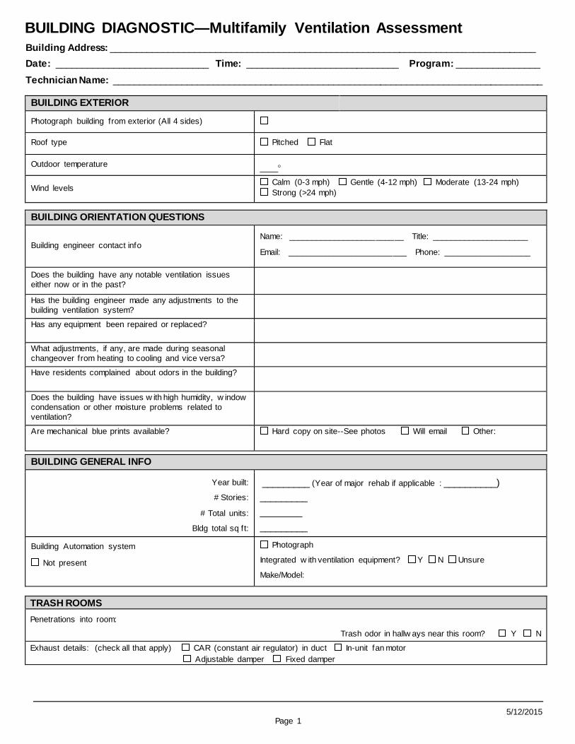
5/12/2015 Page 1
BUILDING DIAGNOSTIC—Multifamily Ventilation Assessment
Building Address: _________________________________________________________________________________
Date: _____________________________ Time: _____________________________ Program: ________________
Technician Name: __________________________________________________________________________________
BUILDING EXTERIOR
Photograph building from exterior (All 4 sides)
Roof type Pitched Flat
Outdoor temperature ____
Wind levels Calm (0-3 mph) Gentle (4-12 mph) Moderate (13-24 mph)
Strong (>24 mph)
BUILDING ORIENTATION QUESTIONS
Building engineer contact info Name: _________________________ Title: _____________________
Email: __________________________ Phone: ___________________
Does the building have any notable ventilation issues
either now or in the past?
Has the building engineer made any adjustments to the
building ventilation system?
Has any equipment been repaired or replaced?
What adjustments, if any, are made during seasonal
changeover from heating to cooling and vice versa?
Have residents complained about odors in the building?
Does the building have issues w ith high humidity, w indow
condensation or other moisture problems related to
ventilation?
Are mechanical blue prints available? Hard copy on site--See photos Will email Other:
BUILDING GENERAL INFO
Year built:
# Stories:
# Total units:
Bldg total sq ft:
_________ (Year of major rehab if applicable : __________)
_________
________
_________
Building Automation system
Not present
Photograph
Integrated w ith ventilation equipment? Y N Unsure
Make/Model:
TRASH ROOMS
Penetrations into room:
Trash odor in hallw ays near this room? Y N
Exhaust details: (check all that apply) CAR (constant air regulator) in duct In-unit fan motor
Adjustable damper Fixed damper

Building Diagnostic: Multifamily Ventilation Assessment Building Address:
Page 2
ROOFTOP: CENTRAL EXHAUST FANS
Total number rooftop exhaust fans: ____
General photo of roof layout General photo of each fan
Nameplate photo of each Nameplate not visible
Mechanical Blue Prints photos Photo of roof layout Photo of shaft risers
Tag Model Belt driv e /
Direct Driv e
Speed
control?
# Units
serv ed
Flow requirement
for inlets serv ed
Measured outlet
flow (cfm) Flow/unit
1 BD DD Y N
2 BD DD Y N
3 BD DD Y N
4 BD DD Y N
5 BD DD Y N
6 BD DD Y N
7 BD DD Y N
8 BD DD Y N
9 BD DD Y N
10 BD DD Y N
11 BD DD Y N
12 BD DD Y N
Evidence of moisture, condensation in areas served by system? Y N
CORRIDOR AIR HANDLERS Photos: General system photo Outdoor air intake Air Handler Nameplate Motor Nameplate
Tag
Description of area served Location
Hrs of
operation/
day
Type of
air heat /
cool Dirty filter?
Blocked bird
screen or
filter?
Damper open /
operable?
Req’d OA
flow Measured OA flow Overage
1
2
3
4
5
6
NOTES:
ROOFTOP: TRASH CHUTE EXHAUST TERMINATION Open exhaust area: < or = to 75 inches² > 75 inches²
NOTES:

Building Diagnostic: Multifamily Ventilation Assessment Building Address:
Page 3
EXHAUST INLETS
Unit Flr
#
Bdrms
#
Baths
Room
Ft²
PRV
Shaft
(tag)
Flow
Req’d
Inlet
location
(Ktichen/
bath)
Exh
flow
(cfm): Static
Pressure
Damper
position
(open or closed?)
Dusty /
Blocked
1
2
3
4
5
6
7
8
9
10
11
12
13
14
15
16
17
18
19
20
21
22
23
24
25
26
27
28
29
30
31
32
33
34
35
36
37
38

Building Diagnostic: Multifamily Ventilation Assessment Building Address:
Page 4
APARTMENT TYPES See blue prints
Type # Bdrms # Baths Area (Ft2) Kitchen area (Ft2) Central exhaust
inlet location (s)
HALLWAYS AND COMMON AREAS see blue prints
Air handler 1 tag: Area type AND ft2 per area
Air handler 2 tag: Area type AND ft2 per area
Air handler 3 tag:
Area type AND ft2 per area
NOTES:

Building Diagnostic: Multifamily Ventilation Assessment Building Address:
Page 5

Building Diagnostic: Multifamily Ventilation Assessment Building Address:
Page 6
Summary Workscope Summary
Trash Chute: adjust cap / air seal trash rooms / exhaust fan (circle one)
Air sealing notes:
Trash room exhaust overage:
Notes:
Corridor ventilation system overage:
Notes:
Exhaust ventilation overage:
Notes:
Replace / Modify exhaust fans
Notes:
Major duct inconsistencies—recommend duct repair before reducing flows
Notes:
Seal duct leakage at curb
Seal branch inlet at ceiling/wall
Other observations
Moisture issues: ________________________________________________________________________
Odor issues: ___________________________________________________________________________
Blocked inlets: __________________________________________________________________________
Disconnected duct: _____________________________________________________________________
No flow/low flow: _______________________________________________________________________
High flow: ___________________________________________________________________________
Fan noise issues: _______________________________________________________________________
Management concerns: _____________________________________________________________________________
________________________________________________________________________________________________________
Notes:
_________________________________________________________________________________________
_________________________________________________________________________________________
_________________________________________________________________________________________

Appendix 8
Example of a Ventilation
Assessment Report
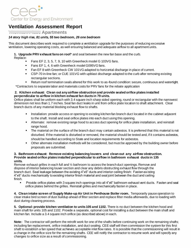
Ventilation Assessment Report Thornton Place Apartments 14 story high rise, 81 units, 55 two bedroom, 26 one bedroom
This document describes work required to complete a ventilation upgrade for the purposes of reducing excessive ventilation, lowering operating costs, as well ensuring balanced and adequate airflow to all apartment units.
1. Upgrade PRV exhaust fans on roof* and seal between the new fan base and the curb. Replace:
Fans EF 2, 3, 5, 7, 9, 10 with Greenheck model G 103VG fans.
Fans EF 1, 4, 6 with Greenheck model G095VG fans.
Fan EF 8 with Greenheck CW 101VG adapted to horizontal discharge in place of current.
CSP-70 in-line fan; or CUE 101VG with upblast discharge adapted to the curb after removing existing
rectangular sections.
Return roof termination seals altered for this work to as-found condition: secure, continuous and watertight.
*Contractors to separate labor and materials costs for PRV fans for the rebate application
2. Kitchen exhaust: Clean out any airflow obstruction and provide sealed orifice plates installed perpendicular to airflow in kitchen exhaust fan ducts in 79 units. Orifice plates shall be uniform each with 3.4 square inch sharp sided opening, round or rectangular with the narrowest dimension not less than 1.7 inches. Seal fan duct leaks in unit from orifice plate location to shaft attachment. Clear branch ducts of any material blocking exhaust flow to shafts.
Installation: provide access or opening to existing kitchen fan branch duct located in the cabinet adjacent
to the shaft. Install and seal orifice plates into each duct using this opening.
Alternate: remove existing range hood to access duct opening for orifice plate installation, and reinstall
range hood.
The material on the surface of the branch duct may contain asbestos. It is preferred that this material is not
disturbed. If the material is disturbed or removed, the material should be tested and, if it contains asbestos,
should be handled according to State and location requirements for asbestos.
Other alternate installation methods will be considered, but must be approved by the building owner before
proposals are submitted.
3. Bathroom exhaust: Remove existing balancing louvers and clean out any airflow obstruction. Provide sealed orifice plates installed perpendicular to airflow in bathroom exhaust ducts in 135 units. Remove exhaust grilles in each full and ½ bathroom to access the branch duct openings. Remove and dispose of interior balancing louver section and clear any debris obstructing exhaust flow through the branch duct. Seal leakage between the existing 4”x6” ducts and interior ceiling finish: Fasten ex isting 4”x6” ducts mechanically to existing interior finish material and seal joint between the duct and ceiling finish.
Provide orifice plates with 3 square inch openings into all 4”x6” bathroom exhaust vent ducts. Fasten and seal orifice plates behind the grilles. Reinstall grilles and mechanically fasten in place.
4. Clean intake screen of Supply Make-up Air Unit in Penthouse Boiler room. Temporarily pause operation to clear intake bird screen of dust buildup ahead of filter section and replace filter media afterwards, due to loading with dust during cleaning process.
5. Optional: provide kitchen ventilation to units 105 and 1102. There is no duct between the kitchen hood and main shaft for units 105 and 1102. Provide a separate, optional cost for installing a duct between the main shaft and kitchen fan. Include a 3.4 square inch orifice (as described above) in each.
Note: The contractor will perform the retrofit work for one of the shafts before continuing work on the remaining shafts; including fan replacement, orifice installation, and duct sealing. CEE staff will then commission the system for this first shaft to establish a fan speed that achieves acceptable inlet flow rates. It is possible that the commissioning will result in a change in the orifice size for the remaining shafts. CEE will notify the contractor to resume work and will specify any changes to orifice size as a result of commissioning.

Energy savings summary The modifications to the exhaust air systems will reduce the outside air flow rate by about 2,299 cubic feet per minute and
will save energy costs associated with exhausting conditioned air. The recommended high-efficiency PRV motors will save
considerable electricity. Energy savings is summarized below:
Estimated annual gas savings $3,341 4,706 therms
Estimated annual electricity savings $1,978 21,979 kWh
Estimated utility rebate amount $4,200 (First yr only)
Quality Assurance Verification Measures
1. CEE will verify a sample of PRV exhaust flows after work is complete to ensure flow rates within 20% of target
flow rates.
2. CEE will measure a sample of flows in apartment inlets throughout the building to verify equitable distribution of
exhaust ventilation to all units.
Inlet flows should measure within 20% of target flow rate
If measured flow rates are not within 20% of the target rate, CEE work with the installing contractor to resolve any
problems with the installation.
212 3rd Ave N, Suite 560 Minneapolis, MN 55401 www.mncee.org main 612.335.5888 direct 612.244.2425

Appendix 9
Example of an Exhaust System Work Scope
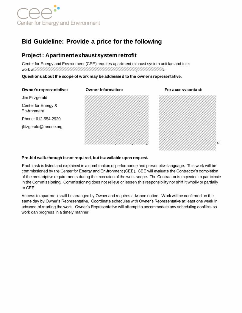
Bid Guideline: Provide a price for the following
Project : Apartment exhaust system retrofit
Center for Energy and Environment (CEE) requires apartment exhaust system unit fan and inlet
work at Seward Tower East, 2910 East Franklin Avenue, Minneapolis, MN 55406.
Questions about the scope of work may be addressed to the owner’s representative.
Owner’s representative:
Jim Fitzgerald
Center for Energy &
Environment
Phone: 612-554-2920
Owner Information:
Seward Redesign for Seward
Towers Corporation
Nancy St. Germaine-Diaz
Project Manager, Redesign, Inc.
Office: 612.435.0276
Cell: 612.209.2045
Email: [email protected]
For access contact:
Bruce Pfannes, Maintenance
supervis
Maintenance Supervisor
612 230-1421
651-587-2960 cell
612-339-9018 fax
Bruce.Pfannes@commonbond.
org
Pre-bid walk-through is not required, but is available upon request.
Each task is listed and explained in a combination of performance and prescriptive language. This work will be
commissioned by the Center for Energy and Environment (CEE). CEE will evaluate the Contractor’s completion
of the prescriptive requirements during the execution of the work scope. The Contractor is expected to participate
in the Commissioning. Commissioning does not relieve or lessen this responsibility nor shift it wholly or partially
to CEE.
Access to apartments will be arranged by Owner and requires advance notice. Work will be confirmed on the
same day by Owner’s Representative. Coordinate schedules with Owner’s Representative at least one week in
advance of starting the work. Owner’s Representative will attempt to accommodate any scheduling conflicts so
work can progress in a timely manner.

Page 2 of 3
Scope to include the following:
Single Shaft Exhaust system upgrade
Reduce excess flow and electrical power use by replacing the PRV fan with a properly sized EC type fan. Balance attached inlets with fixed orifice plates to provide the code required flow from each unit.
Performance Criteria
With the fan and all orifices installed, set the speed control on the G-095 VG fan to 1200 RPM to start. Check kitchen inlet flow in room 209, adjust fan speed as needed to get flow between: Studio: 8 -10 cfm 1 bedroom: 18-23cfm 2 bedroom: 28- 36cfm
Specific requirements include:
Location Kitchens in units 209-2109 on floors 2-21
Number of inlets 20
Existing fan Greenheck GB-161-4
New PRV fan Greenheck G-095 VG ¼ HP with curb adapter
Inlet Grilles
Inlet type Kitchen, fixed with adjustable dampers and subducts
Inlet register size Nominal 6x8 inch
New orifice adapter plates [Fig 6]
Orifice plate material 26 gauge galvanized steel sheet metal
Orifice diameter in plate Studio kitchens 1-1/4 inch, 1.25 inch
One bedroom kitchens 1-7/8 inches, 1.875 inches
2 bedroom kitchens 2-3/8 inches, 2.375 inches
Commercial orifice option with
CEE approval before work
Reducing washers
Studio: 1 inch ID nominal, 1.365 inch diameter
1 bedroom: 1-1/2 inch ID nominal, 1.97 inch diameter
2 bedroom: 2 inch ID nominal, 2.45 inch diameter
Installation Instructions
Rooftop fan
Remove existing GB-161-4 fan from curb, provide to owner for re-use.
Remove backdraft damper Seal conduit opening in duct and gaps from curb to shaft Provide new G-095VG 1/4hp fan and curb adapter
Unit kitchen inlets
Remove adjustable dampers from kitchen inlet grills, fix in open position, or replace with fixed grilles acceptable to the owner.
Remove any obstructions from inlet branches and subducts, clean dust from register boxes Seal gaps from register to interior finish, and gaps inside register Mount orifice adapter plates 2-4 inches into register perpendicular to the direction of airflow Fasten left and right side tabs of adapter plate with sheet metal screws
If reducing washers are provided, mount on side of plate facing the interior of the unit Seal edges of adapter plates to register sides
Confirm flow
With the fan and all orifices installed, set the speed control on the G-095 VG fan to 1200 RPM to start. Check kitchen inlet flow in room 209, adjust fan speed as needed to get flow between:
Studio: 8 -10 cfm 1 bedroom: 18-23cfm 2 bedroom: 28- 36cfm

Page 3 of 3
Figures
Fig 1. Subducts in K 4/6 shaft, no visible leaks Fig 2. 9-Kit shaft offset , single subducts in similar K 15 shaft
Fig 3. Kitchen inlet grille from 216, typical Fig 4. Adjustable dampers: remove, fix open, or use fixed grille
Fig 5. Register behind grille
Fig. 6 Orifice plate with 2.45 inch reducing washer, 2 bedroom
Fig 8. Adjust G-095VG fan

Appendix 10
Example of a Supply/Corridor System
Work Scope

Bid Request: provide a price for the following
Project: Re-sheave, Test and Balance on corridor make up air unit
Questions about the scope of work may be addressed to the owner’s representative.
Owner’s representative:
Gustav Brändström, PE
Center for Energy & Environment
Minneapolis, MN 55401
Voice: 612-335-5886
Owner Information:
Dan Paulson
Ebenezer Towers Apartments
2523 Portland Ave South
Minneapolis, MN
Each task is listed and explained in a combination of performance and prescriptive language. This work will be
commissioned by the Center for Energy and Environment (CEE) and will be the Owner’s Representative. CEE
will evaluate the Contractor’s completion of the prescriptive requirements during the execution of the work scope.
The Contractor is expected to participate in the Commissioning. Commissioning does not relieve or lessen this
responsibility nor shift it wholly or partially to CEE.
The Test and Balance Contractor shall submit the following for approval by CEE:
Submit report forms or outlines indicating adjusting, balancing, and equipment data required along with calibration information on all test equipment that will be used to complete work scope.
Submit detailed procedures, agenda, and sample report forms.
Test and Balance work will be witnessed by Owner’s Representative. Coordinate schedules with Owner’s
Representative at least one week in advance of starting the balancing work. Owner’s Representative will attempt
to accommodate any scheduling conflicts so work can progress in a timely manner.
Test and Balance Contractor shall balance systems with within +/-10 percent of the design.
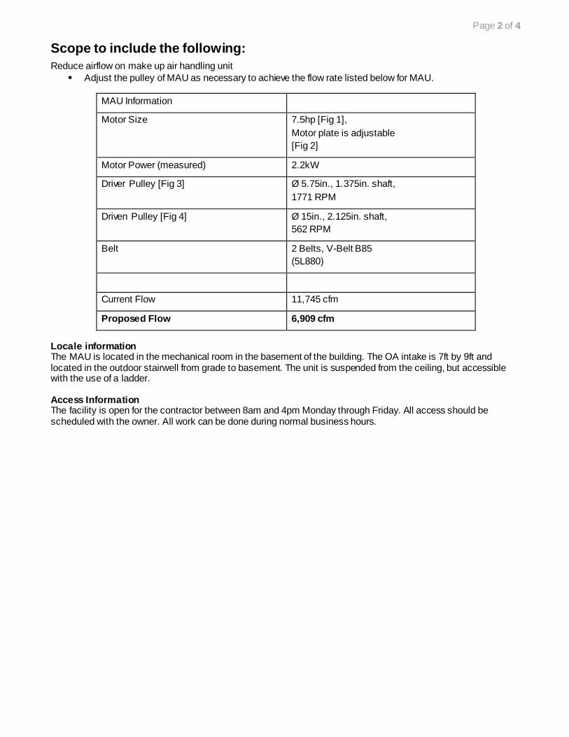
Page 2 of 4
Scope to include the following:
Reduce airflow on make up air handling unit
Adjust the pulley of MAU as necessary to achieve the flow rate listed below for MAU.
MAU Information
Motor Size 7.5hp [Fig 1],
Motor plate is adjustable
[Fig 2]
Motor Power (measured) 2.2kW
Driver Pulley [Fig 3] Ø 5.75in., 1.375in. shaft,
1771 RPM
Driven Pulley [Fig 4] Ø 15in., 2.125in. shaft,
562 RPM
Belt 2 Belts, V-Belt B85
(5L880)
Current Flow 11,745 cfm
Proposed Flow 6,909 cfm
Locale information The MAU is located in the mechanical room in the basement of the building. The OA intake is 7ft by 9ft and located in the outdoor stairwell from grade to basement. The unit is suspended from the ceiling, but accessible with the use of a ladder. Access Information The facility is open for the contractor between 8am and 4pm Monday through Friday. All access should be scheduled with the owner. All work can be done during normal business hours.

Page 3 of 4
Figures.
Figure 1. Motor nameplate.
Figure 2. Motor plate and pulleys.

Page 4 of 4
Figure 3. Drive pulley
Figure 4. Driven pulley

Appendix 11
Example of a Trash Chute System
Work Scope

212 3rd Ave N, Suite 560 Minneapolis, MN 55401
www.mncee.org main 612.335.5888 D Bohac direct 612.335.5866
Bid Request: provide a price for the following
Project : trash chute upgrade at Chateau Cooperative
425 13th Avenue SE, Minneapolis, MN
20 story hi rise, 127 units
Purpose: Reduce uncontrolled exhaust and control trash odor
Complete the following work in the main floor mechanical room:
1. Install a sheet metal or durable membrane closure from compactor inlet to bottom of trash chute. Seal
fixed gaps and joints with RTV Silicone or equivalent elastomeric sealant. Maintain free operation of
damper, visibility of label, and access for inspection.
2. Furnish and install an accordion fire damper discharge door for a 24 inch trash chute. Accordion fire
damper shall bear a 1-1/2 hour UL label. Available from Chutes Inc. see attachment
3. Provide gasket under movable metal cover at compactor drive in rear and close cover, allow
continued access
4. Close gap between compactor and attached dumpster. Allow continued dumpster exchange and
operation of clamp mechanism. Material for gasket: heavy duty hose* or equivalent
5. Close dumpster lid. Provide sign on compactor “keep dumpster closed” or equal.
6. Performance test: observe chemical smoke draw at dumpster lid edges and joints in trash chute
assembly.
*Durable and flexible reinforced hose:
Conforms to fill gap to dumpster and returns to original cross section after compression
Mounted to perimeter of compactor opening, mechanically fastened
Sized to meet frame of dumpster opening approximately 33 x 32
Acceptable material:1-1/2” 3-ply Silicone Hose, part 027024166, sample provided
Able Hose and Rubber, R Weidell
2340 County C West, Suite 150
Roseville, MN 55113
612 378 1003 phone
612 378 1199 fax
For further information contact Jim Fitzgerald, CEE at 612 554 2920
Provide bids to David Bohac, CEE, 212 Third Avenue North, Suite 150, Mpls, MN 55401
This work will be commissioned by the Center for Energy and Environment (CEE). CEE will evaluate the
Contractor’s completion of the prescriptive requirements during the execution of the above listed tasks. The
Contractor is expected to participate in the Commissioning. Commissioning does not relieve or lessen this
responsibility nor shift it wholly or partially to CEE.

Install sheet metal or durable membrane closure that will seal
compactor inlet to bottom of trash chute.
Install gasket at perimeter of compactor outlet
to dumpster.
Install fire damper at bottom of outlet