multi-dimensional optimization of small wind turbine … · multi-dimensional optimization of small...
TRANSCRIPT
Sessarego and Wood Renewables: Wind, Water, and Solar (2015) 2:9 DOI 10.1186/s40807-015-0009-x
ORIGINAL RESEARCH PAPER Open Access
Multi-dimensional optimization of smallwind turbine blades
Matias Sessarego1,2 and David Wood2*Abstract
This paper describes a computer method to allow the design of small wind turbine blades for the multipleobjectives of rapid starting, efficient power extraction, low noise, and minimal mass. For the sake of brevity, onlythe first two and the last objectives are considered in this paper. The optimization aimed to study a range of bladematerials, from traditional fibreglass through sustainable alternatives to rapid prototyping plastic. Because startingperformance depends on blade inertia, there is a complex interaction between the material properties and theaerodynamics. Example blades of 1.1 m length were designed to match a permanent magnet generator with arated power of 750 W at 550 rpm. The materials considered were (a) traditional E-glass and polyester resin; (b) flaxand polyester resin; (c) a typical rapid prototyping plastic, ABS-M30; and (d) timber. Except for (d), hollow bladeswere used to reduce the rotor inertia to help minimize starting time. Two airfoils are considered: the 10% thickSG6043 which has excellent lift:drag performance at low Reynolds number and the SD7062 whose extra thickness(14%) has some structural advantages, particularly for the weaker material (c). All blade materials gave feasibledesigns with material (d) the only one that required a blade shell thickness greater than the specified minimumvalue of 1% of the blade chord. Generally, the blade chord and twist increased as starting was given greaterimportance. In all cases, the associated increase in blade inertia was outweighed by the larger aerodynamictorque. Materials (a), (b), and (d) were better suited to the SG6043 airfoil whereas ABS-M30 benefitted from thethicker SD7062 section.
Keywords: Small wind turbines; Blade design; Multi-dimensional optimization; Power; Starting performance
BackgroundSmall wind turbines are under strong competitivepressure from photovoltaics (PV) which have decreasedsignificantly in price over the past decade. A similarreduction in the manufacturing cost of small wind tur-bines is probably not achievable, but significant effortscan be made in this direction. For example, the recentincrease in the use of monopole towers may well bereversed and the cheaper lattice tower gain renewedapplication (Adhikari et al. 2014a).In addition, there are two aspects of small wind tur-
bines that will remain attractive. The first is that remoterenewable energy systems generally should use multipleresources, such as sun and wind, to provide the mostcost-effective system despite any cost difference between
* Correspondence: [email protected] of Mechanical and Manufacturing Engineering, University ofCalgary, Calgary, AB, CanadaFull list of author information is available at the end of the article
© 2015 Sessarego and Wood. This is an OpenLicense (http://creativecommons.org/licenses/bmedium, provided the original work is properly
the technologies (e.g. Kaldellis 2010). Second, mostdeveloping countries must import PV equipment,whereas there is scope for significant local manufactureof many wind turbine components, often using indi-genous and sustainable materials, such as bamboo forthe tower (Adhikari et al. 2014b) and timber or bio-composites and bio-resins for the blades (Peterson andClausen 2004, Holmes et al. 2009, Astle et al. 2013, andShah et al. 2013). In addition, the recent advent of rapidprototyping brings the promise of cheap manufactureof the complex three-dimensional blade shape and thepotential to design blades for specific applications, suchas rapidly starting blades for low-wind areas or espe-cially quiet blades for building mounting.In order to exploit these opportunities, the small wind
turbine blade design must become increasingly multi-dimensional. Starting is often a critical issue for smallblades as most do not have pitch adjustment. Recenttwo-dimensional optimizations considered starting and
Access article distributed under the terms of the Creative Commons Attributiony/4.0), which permits unrestricted use, distribution, and reproduction in anycredited.
Sessarego and Wood Renewables: Wind, Water, and Solar (2015) 2:9 Page 2 of 11
power extraction (Wood 2011, Pourrajabian and Mirzaei2014, and Shah et al. 2014). Clifton-Smith (2010) addednoise. The common finding of these studies is that amulti-dimensional design is actually a trade-off. Typic-ally, the most powerful blade is the slowest to start andClifton-Smith (2010) found that for blades of nearlyequal power extraction, the quietest blade was the slow-est to start whereas the fastest starting blade was thenoisiest.Of the papers just cited, only Pourrajabian and Mirzaei
(2014) considered structural optimization which isimportant for large-blade design partly because blademanufacturing cost correlates with blade weight (e.g.Sessarego et al. 2014). Structure is important for smallblades in another way: starting depends on the aero-dynamic torque generated by the blade shape and isimproved by a low blade inertia, JB, which depends onshape, material, and manufacturing technique. It is tobe expected that including structure in small-bladeoptimization will introduce complex interactions be-tween the objective functions. To fully exploit the pos-sibilities of structural optimization, it is necessary todesign hollow blades, whose shell thickness can beminimized to reduce JB while remaining sufficientlystrong. Examples of hollow composite small turbineblades are given in Clausen et al. (2013).The aim of this paper is to explore multi-dimensional
small wind turbine blade optimization including struc-ture, by designing hollow blades using (a) traditionalE-glass and polyester; (b) flax and polyester; (c) a strong,rapid prototyping material; and (d) solid blades usingtimber. The 1.1-m-long blades were designed to match apermanent magnet generator with a rated capacity of750 W at 550 rpm and efficiency of 74%. Solid timberblades for this generator were designed in Chapter 7 ofWood (2011). The optimizations use the MATLAB codeSmall Wind-turbine Rotor Design Code (SWRDC)developed by the authors and available from them. Thecode combines the multi-objective problem in a singleobjective by using a scalarization function of all theobjective functions, as explained below. Optimization isby a simple genetic algorithm.Material (a) is typical of many current small blades.
The use of flax rather than E-glass in material (b) is oneway to reduce the environmental footprint of smallblades (Shah et al. 2013). Timber, material (d), is com-monly used for ultralight aircraft propellers and alsomay be environmentally preferable to material (a). Hooppine is a native Australian tropical pine that grows wellin plantation (Peterson and Clausen 2004) and has beenused for many years for propeller manufacturea. It ispossible that the advent of rapid prototyping or three-dimensional printing will revolutionize small-blademanufacture because it does not need expensive moulds
and allows specific blade design for specific site condi-tions. For example, a windy site may not require rapidlystarting blades, whereas a turbine to be installed nextto a house may need to be extremely quiet. SWRDC isa very suitable tool to undertake the initial design ofblades for different requirements. However, there isone major concern with rapid prototyping materials: anextensive search of the literature has found none whosefatigue properties have been established. Although it is notdirectly considered in the present optimization, adequatefatigue behaviour is essential for any blade to be safe.It is common to use a single airfoil for small blades as
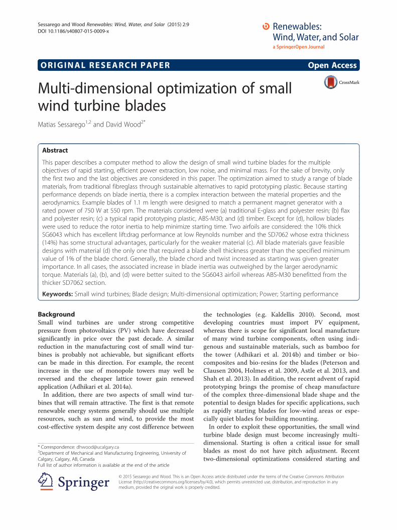
the large-blade practice of increasing the airfoil thicknessnear the root will cause undesirable aerodynamic behav-iour at the low chord Reynolds number, Re, encounteredby small blades (e.g. Wood 2011). The first airfoil con-sidered here is the SG6043 developed for small wind tur-bines by Giguere and Selig (1998). As seen in Figure 1,this airfoil has an outstanding lift to drag ratio which isnecessary to maximize power output. The SG6043 has amaximum thickness of 10% which may cause high stresslevels near the root, so the 14% thick SD7062 (Giguereand Selig 1997) was also considered. Figure 1 shows thatit has a good lift to drag ratio but is likely to produceless power than the SG6043. The noise analysis is thatused by Clifton-Smith (2010) which was based on thesemi-empirical formulation of Zhu et al. (2005). Thisobjective function will not be described in detail as it isnot used in this study.One of the prime requirements for multi-dimensional
optimization involving the evaluation of thousands ofobjective functions is their rapid evaluation. Therefore,it is not possible to use, say, detailed computationalfluid dynamics or finite element structural analysis. Theoptimization results from SWRDC cannot be consideredas final designs until validated or modified by higher-fidelity simulations. It is also necessary to emphasize thatthe optimization is of the aerodynamic part of the bladeand excludes the structurally important connection tothe turbine hub. This ‘attachment section’ typically doesnot contribute substantially to the blade inertia but islikely to carry the major blade load, the root bendingmoment. The assumption of hollow blades may also bea significant simplification. Some small blades use afoam core to separate the blade surfaces and preventbuckling (e.g. Clausen et al. 2013), and it is also possiblefor small blades to have a shear web or spar as do largeblades. These additional structural features are not con-sidered here.The next section demonstrates the importance of
starting and describes its aerodynamic modelling using amodified blade element analysis. This is followed by adescription of the structural analysis. Power extractionuses standard blade element theory (e.g. Hansen 2008,
0 1 2 3 4 5 6 720
40
60
80
100
120
Max
imum
lift:
dra
g
Reynolds Number x10-5
NACA 4412
SG 6041
SD 7062
SG 6043MEL 081
Figure 1 Airfoil lift to drag ratio at low Reynolds number from Wood (2011).
Sessarego and Wood Renewables: Wind, Water, and Solar (2015) 2:9 Page 3 of 11
Wood 2011, and Sessarego 2013). The last referencedescribed the detailed validation of the code in referenceto the NREL code Wt_Perf using the AWT-27 turbineperformance data (Buhl 2012).
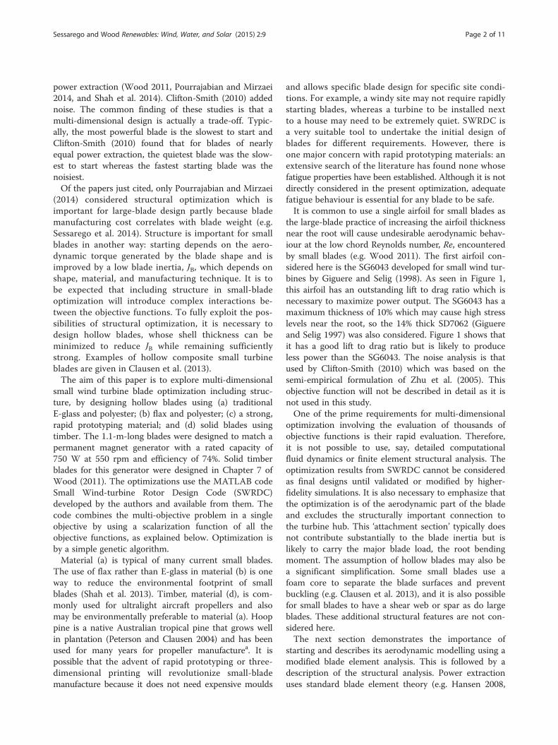
MethodsStarting performance and starting timeFigure 2a shows a high-speed starting sequence of the two-bladed 5-m-diameter 5-kW wind turbine at the Universityof Newcastle, Australia, depicted in Figure 2b. The bladeswere designed by the second author for good startingperformance using the analysis that is described below.Starting is important for small turbine blades which have
Figure 2 High-speed starting sequence of the two-bladed 5-m-diameter 5the 5-kW turbine shown in (b).
no pitch adjustment as the stationary or slowly rotatingblades experience high angles of attack, α, which generatelow aerodynamic torque and lead to long starting times inwhich no power is extracted. Figure 2a indicates that thestarting time,Ts, to reach power-extracting angular velocityis about 13 s. Since Ts scales as the inverse of the windspeed, this well-designed turbine takes around 40 s to startat a desirable cut-in wind speed of 3.5 m/s.By assuming that starting is quasi-steady and using the
generic flat plate equations for high angle lift and drag,Wood (2011) determined the aerodynamic torque, Q, fora turbine with N blades of tip radius R, generated by awind speed U as
-kW wind turbine. (a) Measured and calculated starting performance of
Sessarego and Wood Renewables: Wind, Water, and Solar (2015) 2:9 Page 4 of 11
Q ¼ NρU2R3Z 1
rh
1þ λ2r� �1=2
cr sinθp
cosθp−λr sinθp� �
dr
ð1Þ
ρ is the air density, rh is the normalized hub radius, andλr is the local speed ratio, which is the product of, r, theradius normalized by R, and λ, the tip speed ratio. Өp isthe blade twist angle, measured from the plane of rotation.If the resistive torque of the drivetrain and generator is Qr,then the tip speed ratio, λ, obeys
dλ
dt¼ R Q−Qrð Þ
JUð2Þ
where J is the rotor inertia. For turbines of all sizes, J isdominated by the blade inertia, JB (Wood 2011), so thatJ ~NJB. If Qr can be neglected, as in the example shownin Figure 2, then starting becomes independent of thenumber of blades. Figure 2a shows the solution ofEquations 1 and 2 obtained using the Adams-Moultonmethod and the measured U. The equations are a goodfit to the measurements for the period of slow acceler-ation, up to around 11 s, that dominates the starting se-quence. Soon after that point, the angles of attack havereduced significantly and the rotor accelerates rapidly. Ingeneral, Qr cannot be neglected, unless it is less thanabout 1% of the rated torque (Wood 2011). An exampleof its importance is the analysis of altitude effects onsmall-turbine performance by Pourajjabian et al. (2014).The reduction in air density with altitude can requiresignificant blade redesign to achieve rapid starting as thealtitude increases if Qr is not affected by altitude. Qr isassumed to be zero for the present calculations. SWRDCsolves Equations 1 and 2 for a user-specified number ofblade elements; this was 30 for the present calculations.The same number of identical elements is used to findthe power output.
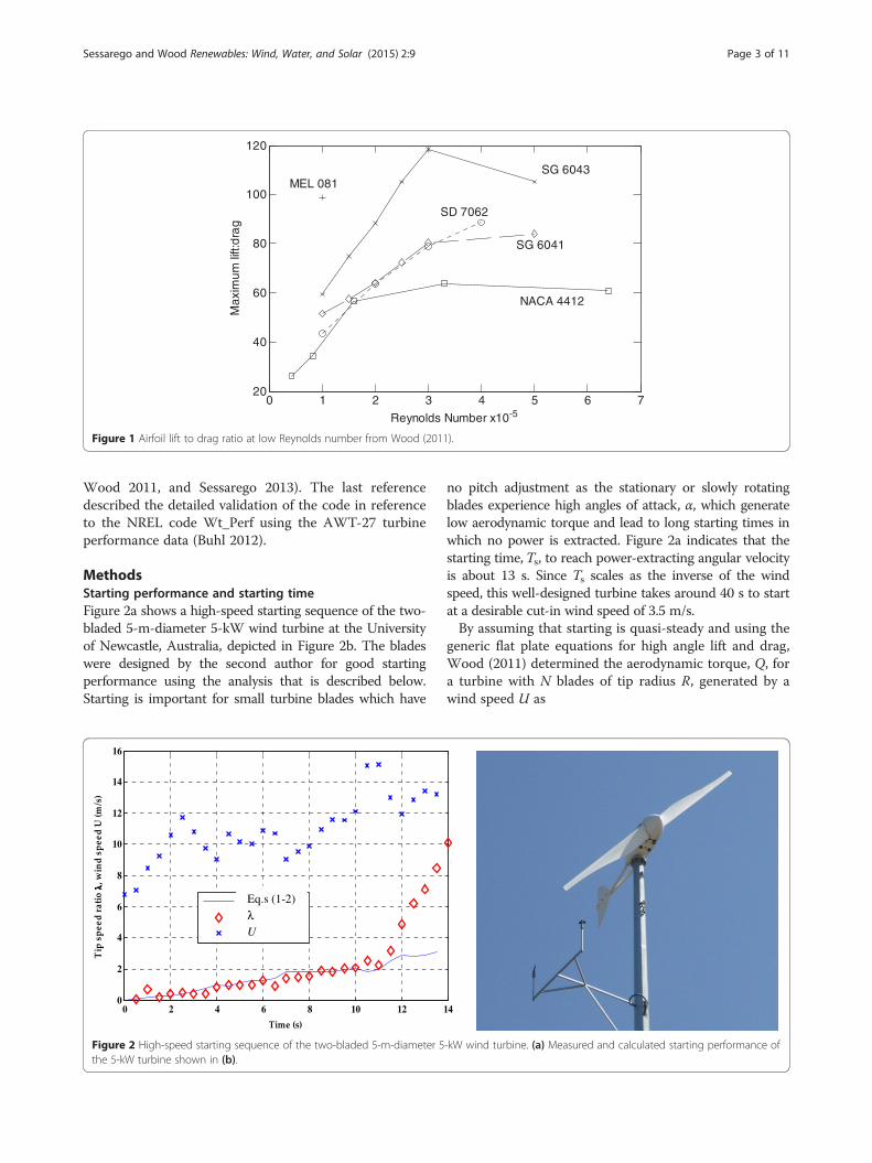
Structural analysisEven though the blade surface shape is determinedlargely by aerodynamic requirements, the structure isvery important. The chosen blade materials must be suf-ficiently strong and resistant to fatigue, and the resultingblade inertia is a key element of the starting perform-ance. This interaction of material properties and aero-dynamics is unique to small blades and is one reasonto include structural analysis in the optimization. Thestructural model is based on simple Euler-Bernoullibeam theory (e.g. Hansen 2008) and is a simpler versionof the one used for large-blade optimization by Sessarego(2013) and Sessarego et al. (2014). They assumed a lay-upconsisting of multiple laminate shells, two shear webs,fore and aft panels, and two spar caps of equal thick-ness. Since small turbine blades often are shells of
thickness, s (Clausen et al. 2013), the structural model isshown in Figure 3. SWRDC assumes s is constant foreach blade element but can vary between elements. Aminimum value of s/c is a necessary user input. Actualwind turbine blades are made from composite aniso-tropic materials, and classical laminate theory or finite-element-based approaches must be used to predictaccurately the blade structural performance (e.g. Chenet al. 2010 and Lin et al. 2010). For the current study,the complexity of the structural analysis is reduced bytreating all materials as isotropic using the materialproperties listed in Table 1. These materials range fromconventional E-glass/polyester through sustainable ma-terials to rapid prototyping plastic. In all cases, the firsttwo material properties were taken directly from thereference. The maximum allowable strain which mustbe an input to SWDRC was calculated as follows, usingE-glass/polyester as an example. Table 2 of Shah et al.(2013) gives the composite strength as 567 MPa. Weassume that this is the ultimate tensile strength (UTS)as is assumed for all other materials. Taking a generous‘safety factor’ of 2 between the UTS and yield strengthgives the latter as 283.5 MPa. The resulting maximumstrain is found from Hooke’s law: 283.5 × 106 = 36.9 ×10⁹ε, where ε is the strain. Thus, ε = 7,684 μstrain. Table2 of Shah et al. (2013) gives the composite fibre failurestrain as 1.9% which is greater than 7,684 μstrain =0.77%, so the latter value is used.The strain is determined around the contour of the
cross-section of each blade element in SWRDC to findthe maximum value. The blade can be solid or hollow;in the latter case, s is calculated to ensure that the allow-able maximum strain is not exceeded.
OptimizationThe present calculations considered only starting andpower extraction. The optimization seeks to
minimize max w1=Cp ið Þ−1=Cp;min
1=Cp;max−1=Cp;min; 1−wð Þ T s ið Þ−Ts;min
Ts;max−Ts;min
� �� �
ð3Þ
for blade i in the current population. Cp is the conven-tional power coefficient at the design wind speed, takento be 10.5 m/s. The weight w (0 ≤w ≤ 1) determines therelative significance of power extraction and starting.When w = 1, the optimization is purely for power. Ts inseconds is the starting time required to reach a tip speedratio at a wind speed specified by the user. Since thecalculations cover only the slow part of starting asshown in Figure 2, the actual values of Ts are not signifi-cant, but the relative magnitude of them is critical.The blade chord and twist are determined using Bézier
curves with a user-specified degree number. The number
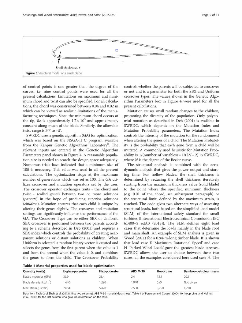
Figure 3 Structural model of a small blade.
Sessarego and Wood Renewables: Wind, Water, and Solar (2015) 2:9 Page 5 of 11
of control points is one greater than the degree of thecurves, i.e. nine control points were used for all thepresent calculations. Limitations on maximum and mini-mum chord and twist can also be specified. For all calcula-tions, the chord was constrained between 0.04 and 0.02 mwhich can be viewed as realistic limitations of the manu-facturing techniques. Since the minimum chord occurs atthe tip, Re is approximately 1.7 × 10⁵ and approximatelyconstant along much of the blade. Similarly, the allowabletwist range is 30° to −5°.SWRDC uses a genetic algorithm (GA) for optimization,
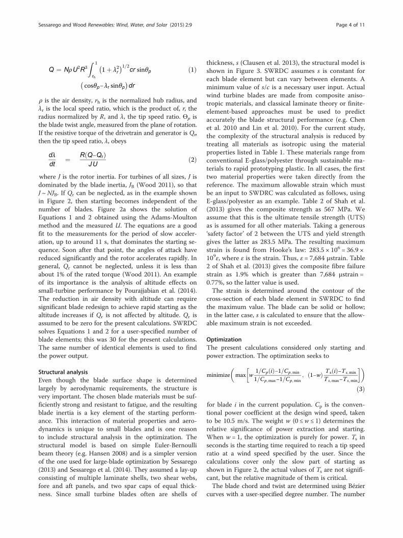
which was based on the NSGA-II C program availablefrom the Kanpur Genetic Algorithms Laboratoryb. Therelevant inputs are entered in the Genetic AlgorithmParameters panel shown in Figure 4. A reasonable popula-tion size is needed to search the design space adequately.Numerous trials have indicated that a minimum size of100 is necessary. This value was used in all the presentcalculations. The optimization stops at the maximumnumber of generations which was set as 100. The GA uti-lizes crossover and mutation operators set by the user.The crossover operator exchanges traits - the chord andtwist - (called genes) between two or more solutions(parents) in the hope of producing superior solutions(children). Mutation ensures that each child is unique byaltering their genes slightly. The crossover and mutationsettings can significantly influence the performance of theGA. The Crossover Type can be either SBX or Uniform.SBX crossover is performed between two parents accord-ing to a scheme described in Deb (2001) and requires aSBX index which controls the probability of creating near-parent solutions or distant solutions as children. WhenUniform is selected, a random binary vector is created andselects the genes from the first parent when the value is 1and from the second when the value is 0, and combinesthe genes to form the child. The Crossover Probability
Table 1 Material properties used for blade optimization
Quantity (units) E-glass-polyester Flax-polyester
Elastic modulus (GPa) 36.9 23.4
Blade density (kg/m3) 1,640 1,290
Max. strain (μstrain) 7,684 5,420
Data from Table 2 of Shah et al. (2013) (first two columns), ABS M-30 material dataet al. (2009) for the last column who gave no information on the resin.
controls whether the parents will be subjected to crossoveror not and is a parameter for both the SBX and Uniformcrossover types. The values shown in the Genetic Algo-rithm Parameters box in Figure 4 were used for all thepresent calculations.Mutation causes small random changes to the children,
promoting the diversity of the population. Only polyno-mial mutation as described in Deb (2001) is available inSWRDC, which depends on the Mutation Index andMutation Probability parameters. The Mutation Indexcontrols the intensity of the mutation (or the randomness)when altering the genes of a child. The Mutation Probabil-ity is the probability that each gene from a child will bemutated. A commonly used heuristic for Mutation Prob-ability is 1/(number of variables) = 1/(2N + 2) in SWRDC,where N is the degree of the Bezier curve.The structural analysis is combined with the aero-
dynamic analysis that gives the power output and start-ing time. For hollow blades, the shell thickness isdetermined by reducing the shell thickness iterativelystarting from the maximum thickness value (solid blade)to the point where the specified minimum thickness(e.g. 0.01 of the chord, see subsequent paragraph) orthe structural limit, defined by the maximum strain, isreached. The code gives two alternate ways of assessingstructural loads, both based on the simplified load model(SLM) of the international safety standard for smallturbines (International Electrotechnical Commission IEC61400–2 ed3.0 (2013)). The SLM defines eight loadcases that determine the loads mainly in the blade rootand main shaft. An example of SLM analysis is given inWood (2011) for a 0.94-m-long timber blade. It is shownthat load case E ‘Maximum Rotational Speed’ and caseH ‘Parked Wind Loads’ gave the greatest blade stresses.SWRDC allows the user to choose between these twocases: all the examples considered here used case H. The
ABS M-30 Hoop pine Bamboo-petroleum resin
2.4 12.1 20.5
1,040 550 Not given
7,500 3,250 4,270
sheetc, Table 1 of Peterson and Clausen (2004) for hoop pine, and Holmes
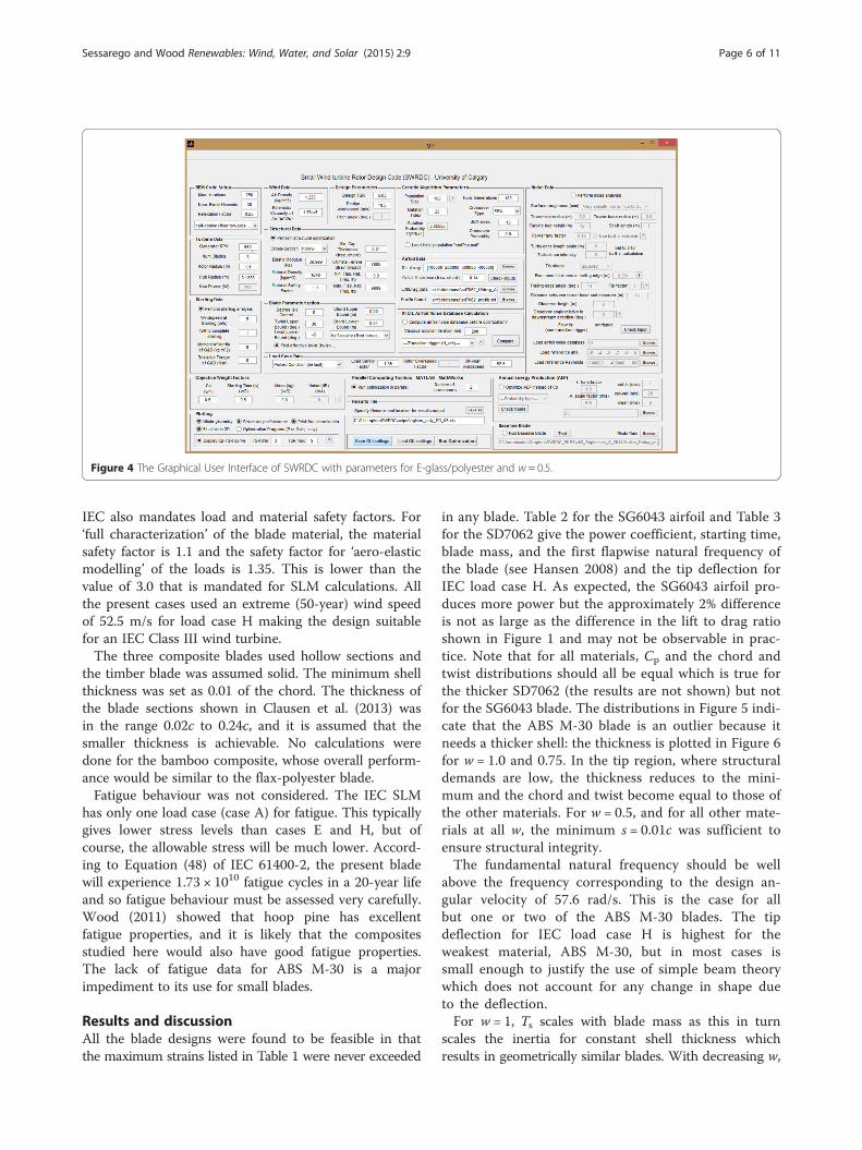
Figure 4 The Graphical User Interface of SWRDC with parameters for E-glass/polyester and w = 0.5.
Sessarego and Wood Renewables: Wind, Water, and Solar (2015) 2:9 Page 6 of 11
IEC also mandates load and material safety factors. For‘full characterization’ of the blade material, the materialsafety factor is 1.1 and the safety factor for ‘aero-elasticmodelling’ of the loads is 1.35. This is lower than thevalue of 3.0 that is mandated for SLM calculations. Allthe present cases used an extreme (50-year) wind speedof 52.5 m/s for load case H making the design suitablefor an IEC Class III wind turbine.The three composite blades used hollow sections and
the timber blade was assumed solid. The minimum shellthickness was set as 0.01 of the chord. The thickness ofthe blade sections shown in Clausen et al. (2013) wasin the range 0.02c to 0.24c, and it is assumed that thesmaller thickness is achievable. No calculations weredone for the bamboo composite, whose overall perform-ance would be similar to the flax-polyester blade.Fatigue behaviour was not considered. The IEC SLM
has only one load case (case A) for fatigue. This typicallygives lower stress levels than cases E and H, but ofcourse, the allowable stress will be much lower. Accord-ing to Equation (48) of IEC 61400-2, the present bladewill experience 1.73 × 10¹⁰ fatigue cycles in a 20-year lifeand so fatigue behaviour must be assessed very carefully.Wood (2011) showed that hoop pine has excellentfatigue properties, and it is likely that the compositesstudied here would also have good fatigue properties.The lack of fatigue data for ABS M-30 is a majorimpediment to its use for small blades.
Results and discussionAll the blade designs were found to be feasible in thatthe maximum strains listed in Table 1 were never exceeded
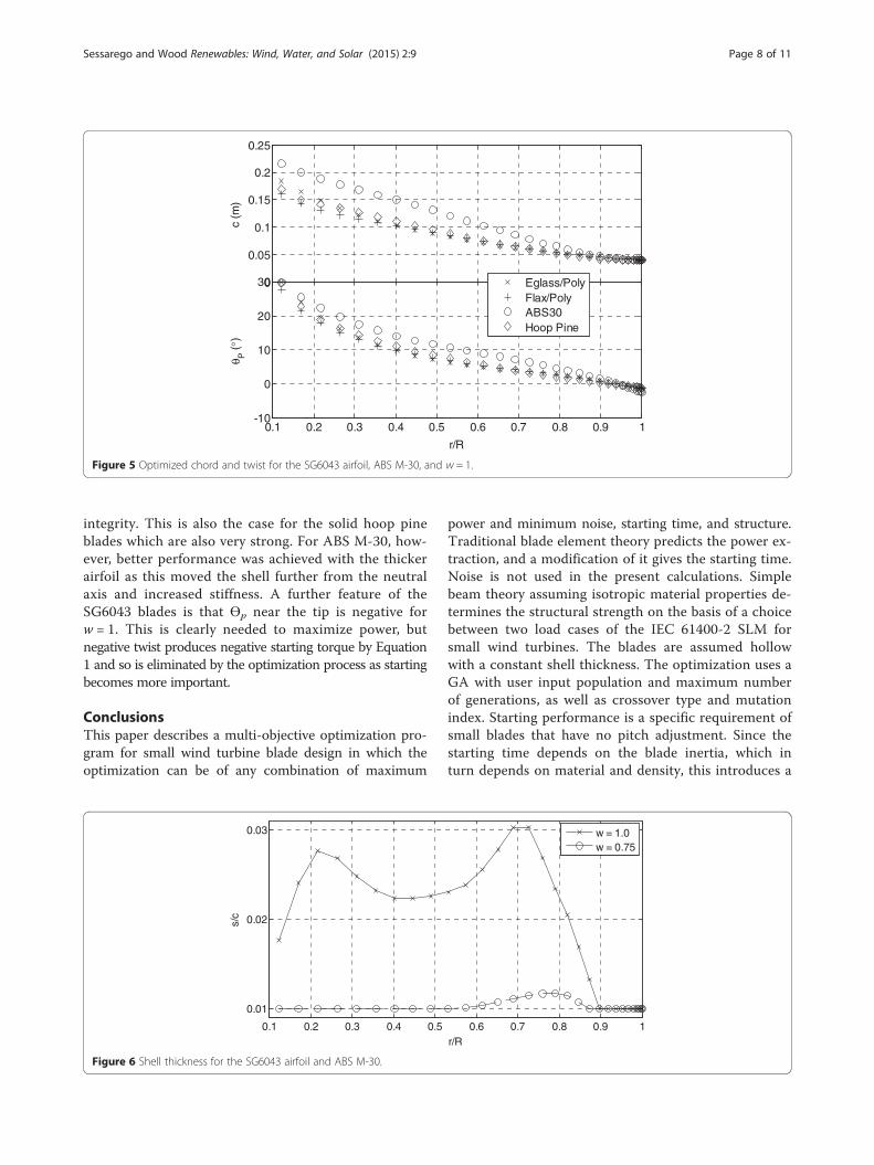
in any blade. Table 2 for the SG6043 airfoil and Table 3for the SD7062 give the power coefficient, starting time,blade mass, and the first flapwise natural frequency ofthe blade (see Hansen 2008) and the tip deflection forIEC load case H. As expected, the SG6043 airfoil pro-duces more power but the approximately 2% differenceis not as large as the difference in the lift to drag ratioshown in Figure 1 and may not be observable in prac-tice. Note that for all materials, Cp and the chord andtwist distributions should all be equal which is true forthe thicker SD7062 (the results are not shown) but notfor the SG6043 blade. The distributions in Figure 5 indi-cate that the ABS M-30 blade is an outlier because itneeds a thicker shell: the thickness is plotted in Figure 6for w = 1.0 and 0.75. In the tip region, where structuraldemands are low, the thickness reduces to the mini-mum and the chord and twist become equal to those ofthe other materials. For w = 0.5, and for all other mate-rials at all w, the minimum s = 0.01c was sufficient toensure structural integrity.The fundamental natural frequency should be well
above the frequency corresponding to the design an-gular velocity of 57.6 rad/s. This is the case for allbut one or two of the ABS M-30 blades. The tipdeflection for IEC load case H is highest for theweakest material, ABS M-30, but in most cases issmall enough to justify the use of simple beam theorywhich does not account for any change in shape dueto the deflection.For w = 1, Ts scales with blade mass as this in turn
scales the inertia for constant shell thickness whichresults in geometrically similar blades. With decreasing w,
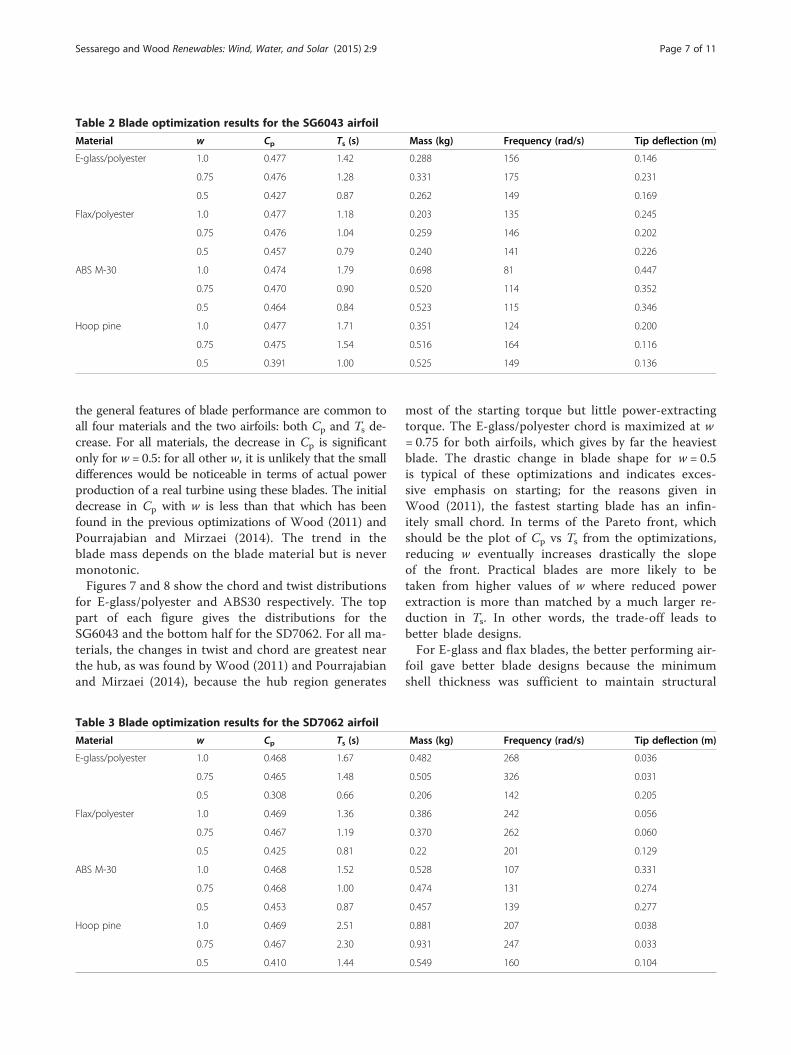
Table 2 Blade optimization results for the SG6043 airfoil
Material w Cp Ts (s) Mass (kg) Frequency (rad/s) Tip deflection (m)
E-glass/polyester 1.0 0.477 1.42 0.288 156 0.146
0.75 0.476 1.28 0.331 175 0.231
0.5 0.427 0.87 0.262 149 0.169
Flax/polyester 1.0 0.477 1.18 0.203 135 0.245
0.75 0.476 1.04 0.259 146 0.202
0.5 0.457 0.79 0.240 141 0.226
ABS M-30 1.0 0.474 1.79 0.698 81 0.447
0.75 0.470 0.90 0.520 114 0.352
0.5 0.464 0.84 0.523 115 0.346
Hoop pine 1.0 0.477 1.71 0.351 124 0.200
0.75 0.475 1.54 0.516 164 0.116
0.5 0.391 1.00 0.525 149 0.136
Sessarego and Wood Renewables: Wind, Water, and Solar (2015) 2:9 Page 7 of 11
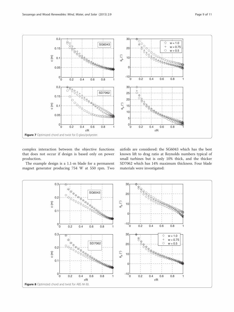
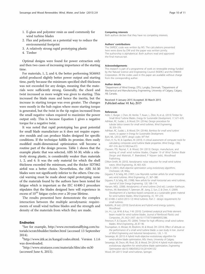
the general features of blade performance are common toall four materials and the two airfoils: both Cp and Ts de-crease. For all materials, the decrease in Cp is significantonly for w = 0.5: for all other w, it is unlikely that the smalldifferences would be noticeable in terms of actual powerproduction of a real turbine using these blades. The initialdecrease in Cp with w is less than that which has beenfound in the previous optimizations of Wood (2011) andPourrajabian and Mirzaei (2014). The trend in theblade mass depends on the blade material but is nevermonotonic.Figures 7 and 8 show the chord and twist distributions
for E-glass/polyester and ABS30 respectively. The toppart of each figure gives the distributions for theSG6043 and the bottom half for the SD7062. For all ma-terials, the changes in twist and chord are greatest nearthe hub, as was found by Wood (2011) and Pourrajabianand Mirzaei (2014), because the hub region generates
Table 3 Blade optimization results for the SD7062 airfoil
Material w Cp Ts (s)
E-glass/polyester 1.0 0.468 1.67
0.75 0.465 1.48
0.5 0.308 0.66
Flax/polyester 1.0 0.469 1.36
0.75 0.467 1.19
0.5 0.425 0.81
ABS M-30 1.0 0.468 1.52
0.75 0.468 1.00
0.5 0.453 0.87
Hoop pine 1.0 0.469 2.51
0.75 0.467 2.30
0.5 0.410 1.44
most of the starting torque but little power-extractingtorque. The E-glass/polyester chord is maximized at w= 0.75 for both airfoils, which gives by far the heaviestblade. The drastic change in blade shape for w = 0.5is typical of these optimizations and indicates exces-sive emphasis on starting; for the reasons given inWood (2011), the fastest starting blade has an infin-itely small chord. In terms of the Pareto front, whichshould be the plot of Cp vs Ts from the optimizations,reducing w eventually increases drastically the slopeof the front. Practical blades are more likely to betaken from higher values of w where reduced powerextraction is more than matched by a much larger re-duction in Ts. In other words, the trade-off leads tobetter blade designs.For E-glass and flax blades, the better performing air-
foil gave better blade designs because the minimumshell thickness was sufficient to maintain structural
Mass (kg) Frequency (rad/s) Tip deflection (m)
0.482 268 0.036
0.505 326 0.031
0.206 142 0.205
0.386 242 0.056
0.370 262 0.060
0.22 201 0.129
0.528 107 0.331
0.474 131 0.274
0.457 139 0.277
0.881 207 0.038
0.931 247 0.033
0.549 160 0.104
0
0.05
0.1
0.15
0.2
0.25
c (m
)
0.1 0.2 0.3 0.4 0.5 0.6 0.7 0.8 0.9 1-10
0
10
20
30
r/R
θ P ( °
)
Eglass/PolyFlax/PolyABS30Hoop Pine
Figure 5 Optimized chord and twist for the SG6043 airfoil, ABS M-30, and w = 1.
Sessarego and Wood Renewables: Wind, Water, and Solar (2015) 2:9 Page 8 of 11
integrity. This is also the case for the solid hoop pineblades which are also very strong. For ABS M-30, how-ever, better performance was achieved with the thickerairfoil as this moved the shell further from the neutralaxis and increased stiffness. A further feature of theSG6043 blades is that Өp near the tip is negative forw = 1. This is clearly needed to maximize power, butnegative twist produces negative starting torque by Equation1 and so is eliminated by the optimization process as startingbecomes more important.
ConclusionsThis paper describes a multi-objective optimization pro-gram for small wind turbine blade design in which theoptimization can be of any combination of maximum
0.1 0.2 0.3 0.4 0.5
0.01
0.02
0.03
s/c
Figure 6 Shell thickness for the SG6043 airfoil and ABS M-30.
power and minimum noise, starting time, and structure.Traditional blade element theory predicts the power ex-traction, and a modification of it gives the starting time.Noise is not used in the present calculations. Simplebeam theory assuming isotropic material properties de-termines the structural strength on the basis of a choicebetween two load cases of the IEC 61400-2 SLM forsmall wind turbines. The blades are assumed hollowwith a constant shell thickness. The optimization uses aGA with user input population and maximum numberof generations, as well as crossover type and mutationindex. Starting performance is a specific requirement ofsmall blades that have no pitch adjustment. Since thestarting time depends on the blade inertia, which inturn depends on material and density, this introduces a
0.6 0.7 0.8 0.9 1r/R
w = 1.0w = 0.75
0 0.2 0.4 0.6 0.8 10
0.05
0.1
0.15
0.2
c (m
)
0 0.2 0.4 0.6 0.8 1-10
0
10
20
30
θ P( °
)
0 0.2 0.4 0.6 0.8 10
0.05
0.1
0.15
0.2
r/R
c (m
)
0 0.2 0.4 0.6 0.8 10
5
10
15
20
25
30
r/R
θ P( °
)
w = 1.0w = 0.75w = 0.5
SD7062
SG6043
Figure 7 Optimized chord and twist for E-glass/polyester.
Sessarego and Wood Renewables: Wind, Water, and Solar (2015) 2:9 Page 9 of 11
complex interaction between the objective functionsthat does not occur if design is based only on powerproduction.The example design is a 1.1-m blade for a permanent
magnet generator producing 754 W at 550 rpm. Two
0 0.2 0.4 0.6 0.8 10
0.1
0.2
0.3
c (m
)
0 0.2 0.4 0.6 0.8 10
0.1
0.2
0.3
r/R
c (m
)
SD7062
SG6043
Figure 8 Optimized chord and twist for ABS M-30.
airfoils are considered: the SG6043 which has the bestknown lift to drag ratio at Reynolds numbers typical ofsmall turbines but is only 10% thick, and the thickerSD7062 which has 14% maximum thickness. Four bladematerials were investigated:
0 0.2 0.4 0.6 0.8 1-10
0
10
20
30
θ P( °
)
0 0.2 0.4 0.6 0.8 1-10
0
10
20
30
r/R
θ P( °
)
w = 1.0w = 0.75w = 0.5
Sessarego and Wood Renewables: Wind, Water, and Solar (2015) 2:9 Page 10 of 11
1. E-glass and polyester resin as used commonly forwind turbine blades
2. Flax and polyester, as a potential way to reduce theenvironmental footprint
3. A relatively strong rapid prototyping plastic4. Timber
Optimal designs were found for power extraction onlyand then two cases of increasing importance of the startingtime.For materials, 1, 2, and 4, the better performing SG6043
airfoil produced slightly better power output and startingtime, partly because the minimum specified shell thicknesswas not exceeded for any design, meaning that the mate-rials were sufficiently strong. Generally, the chord andtwist increased as more weight was given to starting. Thisincreased the blade mass and hence the inertia, but theincrease in starting torque was even greater. The changeswere mostly in the hub region where more starting torqueis generated, but the twist in the tip region increased fromthe small negative values required to maximize the poweroutput only. This is because Equation 1 gives a negativetorque for a negative twist.It was noted that rapid prototyping has great potential
for small blade manufacture as it does not require expen-sive moulds and can produce blades designed for specificconditions. If the technique fulfills its promise, then easilymodified multi-dimensional optimization will become aroutine part of the design process. Table 1 shows that theexample plastic that was selected, ABS M-30, while a rela-tively strong plastic, is considerably weaker than materials1, 2, and 4. It was the only material for which the shellthickness exceeded the minimum, and the thicker SD7062airfoil was a better choice. Nevertheless, the ABS M-30blades were not significantly inferior to the others. One cru-cial warning must be made about rapid prototyping: noneof the materials found by the authors have been tested forfatigue which is important as the IEC 61400-2 procedurestipulates that the blades designed here will experience inexcess of 1010 fatigue cycles over a 20-year lifetime.The results presented here demonstrate the complex
interaction between the multiple aerodynamic require-ments of small wind turbine blades and the strength anddensity of the materials from which they are made.
EndnotesaSee for example, http://www.recreationalflying.com/tu-
torials/scratchbuilder/timber.html (accessed 13 September2014).
bhttp://www.iitk.ac.in/kangal/codes.shtml. Version 1.1.6was downloaded.
chttp://www.stratasys.com/materials/fdm/abs-m30(accessed June 6, 2015).
Competing interestsBoth authors declare that they have no competing interests.
Authors’ contributionsThe SWRDC code was written by MS. The calculations presentedhere were done by DW and the paper was written jointly.The authorship is alphabetical. Both authors read and approvedthe final manuscript.
AcknowledgementsThis research is part of a programme of work on renewable energy fundedby the Natural Science and Engineering Council (NSERC) and the ENMAXCorporation. All the codes used in this paper are available without chargefrom the corresponding author.
Author details1Department of Wind Energy, DTU, Lyngby, Denmark. 2Department ofMechanical and Manufacturing Engineering, University of Calgary, Calgary,AB, Canada.
Received: 9 January 2015 Accepted: 30 March 2015
ReferencesAstle, C, Burger, I, Chen, M, Herrler, T, Kwan, L, Zibin, N, et al,. (2013) Timber for
Small Wind Turbine Blades. Energy for Sustainable Development, 17, 671–676Adhikari, RC, Sudak, L, & Wood, DH. (2014a). Design procedure for
tubular lattice towers for small wind turbines. Wind Engineering,38, 359–376.
Adhikari, RC, Sudak, L, & Wood, DH. (2014b). Bamboo for small wind turbinetowers, to appear in Energy for Sustainable Development.
Buhl, ML. (2012). NWTC design codes: WT Perf.Chen, H, Yu, W, & Capellaro, M. (2010). A critical assessment of computer tools for
calculating composite wind turbine blade properties. Wind Energy, 13(6),497–516. doi:10.1002/we.372.
Clausen, PD, Reynal, F, & Wood, DH (2013) Design, manufacture, andtesting of small wind turbine blades, Chapter 19 of Wind Turbine BladeDesign and Materials, P. Brøndsted, P Nijssen (eds), WoodheadPublishing.
Clifton-Smith, M. (2010). Aerodynamic noise reduction for small wind turbinerotors. Wind Engineering, 34, 403–420.
Deb, K. (2001). Multi-objective optimization using evolutionary algorithms.Chichester, UK: Wiley.
Giguere, P, & Selig, MS. (1997). Low Reynolds number airfoils for small horizontalaxis wind turbines. Wind Engineering, 21, 367–380.
Giguere, P, & Selig, MS. (1998). New airfoils for small horizontal axis wind turbines.Journal of Solar Energy Engineering, 120, 108–114.
Hansen, MOL. (2008). Aerodynamics of wind turbines (2nd ed.). London: Earthscan.Holmes, JW, Brøndsted, P, Sørensen, BF, Jiang, Z, Sun, Z, & Chen, X. (2009).
Development of a bamboo-based composite as a sustainable green materialfor wind turbine blades. Wind Engineering, 33, 197–210.
IEC 61400–2 ed3.0 (2013–12) Wind turbines. Part 2 - design requirements forsmall turbines.
Kaldellis, JK (ed.) (2010) Stand-alone and hybrid wind energy systems,Woodhead
Lin, H-J, Lai, W-M, & Kuo, Y-M. (2010). Combined analytical and finite elementbeam model for wind turbine blades. Journal of Reinforced Plastics andComposites, 29, 2422–2437. doi:10.1177/0731684409352386.
Peterson, P, & Clausen, PD. (2004). Timber for high efficiency small wind turbineblades. Wind Engineering, 28, 87–96.
Pourrajabian, A, Mirzaei, M, Ebrahimi, M, & Wood, DH. (2014). Effect of altitude onthe performance of a small wind turbine blade: a case study in Iran. Journalof Wind Engineering and Industrial Aerodynamics, 126, 1–10.
Sessarego, M. (2013) A hybrid multi-objective evolutionary algorithm forwind-turbine blade optimization, MSc thesis, University of Calgary.
Sessarego, M, Dixon, KR, Rival, DE, & Wood, DH (2014) A hybrid multi-objectiveevolutionary algorithm for wind-turbine blade optimization, EngineeringOptimization doi:10.1080/0305215X.2014.941532
Wood, DH (2011) Small wind turbines, Springer.

Sessarego and Wood Renewables: Wind, Water, and Solar (2015) 2:9 Page 11 of 11
Shah, DU, Schubel, PJ, & Clifford, MJ. (2013). Can flax replace E-glass instructural composites? A small wind turbine blade case study. Composites:Part B, 52, 172–181.
Shah, H, Mathew, S, & Lim, CM. (2014). A novel low Reynolds number airfoildesign for small horizontal axis wind turbines. Wind Engineering, 38, 377–392.
Zhu, W, Heilskov, N, Shen, W, & Sørensen, J. (2005). Modeling of aerodynamicallygenerated noise from wind turbines. Journal of Solar Energy Engineering, 127,517–528.
Submit your manuscript to a journal and benefi t from:
7 Convenient online submission
7 Rigorous peer review
7 Immediate publication on acceptance
7 Open access: articles freely available online
7 High visibility within the fi eld
7 Retaining the copyright to your article
Submit your next manuscript at 7 springeropen.com