multi-channel high speed solution product introduction · multi-channel high speed solution signal...
TRANSCRIPT

Multi-channel high speed solution
Signal Quality Analyzer MP1800A Series 32G Solutions (NRZ / PAM4) 64G Solutions (NRZ / PAM4) High speed serial bus solutions
Product Introduction

2
Multi-channel SQA Solution
Product Overview

3
• Multichannel 20 to 30 Gbit/s is key technology for high-end computers, servers, and 100G / 400G network communications.
• 28 GBaud PAM4 is major technology for 100G / 400G communications. 53G NZR / 53GBaud PAM4 development has started toward the realization of 400 GbE.
Technology trends
GbE/10GbE/10GbE over FEC, 40GbE
52M – 622M 2.4 – 2.6G 9.9G – 10.7G 39.8 – 42.8G
PCIe Gen 1 /2/ 3
SFI5/TFI
Bit rate
Com
mun
icat
ions
Co
mpu
ting
/Dat
a-co
m
1 Gbit/s 10 Gbit/s 40 Gbit/s
11.1G 1.25G 10.3G
Infiniband
2.5G/5G/8GxN
OC-48/OTU1 OC-196/OTU2 OC-768/OTU3 OC-1~12
SFI
2.5G – 10GxN
100 Gbit/s
28Gx4 OTU4
41.3M
XFI CEI-28G
SFI5P2
20 Gbit/s
28G x N
100GbE
14GxN
1GFC, 2GFC, 4GFC, 8GFC, 10GFC+FEC 1.06G x N 10.5G 11.3G
16GFC, 32GFC
32Gx4
25.8GxN
PCIe Gen 4
IB – HDR. NDR IB - FDR, EDR
16GxN
14G, 28G
100G DP-QPSK
USB3.1 Gen1 / Gen2
Thunderbolt
128G FC (28G x 4)
Backplane, Copper: 100GBase-KR4,CR4 100GbE 25.8G x 4
400 Gbit/s
CFP/2/4, QSFP28: 25Gx4, 28Gx4
400GbE 25Gx16
53G PAM4 26.6G PAM4
CEI 28G/56G PAM4
28G NRZ
5G – 10Gbps
OTU5
512G FC

4
NRZ / PAM4 standards • 25G / 50G / 200GbE / 400GbE standardization are on going. • PAM4 becomes major technology for various standards. • Most of PAM4 actual baud-rate is 26.6G. • To assure PAM4 signal Integrity, PAM4 BER measurement is key factors.
Electrical Interface (OIF-CEI) Format Baud-rate
400G CDAUI-16 NRZ 25.8G CDAUI-8 PAM4 26.6G
200G CCAUI-8 NRZ 25.8G CCAUI-4 PAM4 26.6G
100G CAUI-10 NRZ 10.3G CAUI-4 NRZ 25.8G
50G 50GAUI PAM4 26.6G 25G 25GAUI NRZ 25.8G
Optical Interface Electrical Interface Standard Distance Format Baud-rate
400G
400G BASE-SR16 100m NRZ 26.6G 400G BASE-DR4 500m PAM4 53.1G 400G BASE-FR8 2km PAM4 26.6G 400G BASE-LR8 10km PAM4 26.6G
200G
200G BASE-SR8* 100m* NRZ 26.6G 200G BASE-SR4* 100m* PAM4 26.6G 200G BASE-FR4* 2km* PAM4 26.6G 200G BASE-LR4* 10km* PAM4 26.6G
100G
100G BASE-SR10 100m/150m NRZ 10.3G 100G BASE-SR2* 100m* PAM4 26.6G 100G BASE-SR4 70/100m NRZ 25.8G 100G SWDM 400m NRZ 25.8G 100G PSM4 500m NRZ 25.8G CWDM4/CLR4 2km NRZ 25.8G 100G BASE-LR4 10km NRZ 25.8G 100G BASE-ER4 40km NRZ 25.8G 100G BASE-CR4 NRZ 25.8G 100G BASE-KR4 NRZ 25.8G 100G BASE-KP4 PAM4 13.6G
50G 50G BASE-SR* 100m PAM4 26.6G 50G BASE-FR* 2km PAM4 26.6G 50G BASE-LR 10km PAM4 26.6G
25G 25G BASE-SR 100m NRZ 25.8G 25G BASE-FR 2km NRZ 25.8G 25G BASE-LR 10km NRZ 25.8G
*: Under discussion

5
Feature of Anritsu high speed PAM4 / NRZ solutions
32 Gbaud
Multi-channel NRZ solutions
2.4 Gbaud
1 Ch
2 Ch
3 Ch
4 Ch
64 Gbaud
32 Gbit/s PPG + PAM Converter
32 Gbit/s PPG + 64 Gbaud DAC
Multi-channel PAM4 solutions
• Flexible upgradability: Singe channel to Multi channels, PAM4 (Up to 64Gbit/s)
• High quality waveform: Low intrinsic jitter (300 fs @ 28.1Gbps with clock pattern).
• High input sensitivity: 56G/64G DEMUX MP1862A (Typ.25 [email protected] Gbps) 28G/32G ED MU18304xB (Typ.10 [email protected] Gbps)
• Jitter transparent NRZ / PAM4 solutions with various types of jitters

6
Features of 32G All-in-One Jitter BERT Wideband bit rates from 2.4 to 32.1 Gbit/s 1 Tbit/s synchronous BERT : 8ch PPG in one box and 4 boxes
synchronization High-input-sensitivity ED at 10 mV (typical, single-end, Eye Height) Integrated Clock Recovery option with complete jitter tolerance test PAM4 generation and BER measurement
32 Gbit/s x 4ch Tx
32 Gbit/s x 4ch Rx
Various Signal Integrity Analysis Functions
• TJ/DJ/RJ/J2/J9/Bathtub Jitter, Eye Diagram, Eye Margin auto-measurement
• Jitter Tolerance (with MX183000A) SJ = 1UI @ fm: 250 MHz
• 4Tap Emphasis with MP1825B
• Crosstalk testing with individual variable delay
Excellent Signal Quality
and Rx Sensitivity
• Low intrinsic jitter: 300 fs Fast Tr / Tf : 12 ps
• Wide output amplitude range 0.5 to 3.5 V p-p
• High input sensitivity: 10 mV • PAM4 / PAM8 generation
(MZ1834A/MZ1838A) • PAM4 BER Measurement
Supports Data Patterns for Various Applications
• PAM4 PRBS, Gray code etc. • Burst signal test • 256 Mbits / ch max. user
programmable pattern CJTPAT, CJPAT, K28.5 etc.
• Pre-coding, de-coding DQPSK, DP-QPSK

7
MP1861A 56G/64Gbit/s MUX
MP1862A 56G/64Gbit/s DEMUX
2x 32G Data
2x 32G Data
32G Clock
64G Data +
64G Data -
32G Clock
64G Data + 64G Data -
32G Clock
16G Clock
- Jitter Modulator - Synthesizer
- 2ch PPG - 2ch ED
MP1800A Signal Quality Analyzer
Low intrinsic Jitter: RJ = 200 fs rms(typical) Variable amplitude: 0.5 to 3.5 Vp-p Full jitter components generation RJ, BUJ, Dual tone SJ, SSC.
SJ generation 0.55 UI @ fm 250 MHz
High Input sensitivity: 25 mV (typical, single-end, EYE height) Bathtub Analysis as well as Eye Margin, Eye Diagram auto measurement Automatic jitter tolerance test with MX181500A software
PAM4 signal generation up to 64GBaud with DAC Box (G0374A) 56 Gbaud PAM4 BER measurement up to PRBS15
56 Gbit/s signal EYE opening recovery by J1646A (6 dB passive equalizer)
Features of 56G / 64G All-in-One jitter BERT
G0374A 64Gbaud PAM4 DAC
J1646A Passive Equalizer 6 dB(V connector)

8
Multi-channel SQA Solution
28G / 32G Solution

9
Module Lineup
32G PPG 1ch or 2ch
32G ED 1ch or 2ch
Synthesizer (2 Slots)
Synthesizer (2 Slots)
Jitter Generator (2 Slots)
32G ED 4ch (2 Slots)
32G PPG 4ch (2 Slots)
■ 28G/32G BERT Typical Configurations
MP1800A
Max. 6 Slots
28G/32G 8ch Jitter BERT (2 Box ) 32G ED 4ch
(2 Slots) 32G PPG 4ch
(2 Slots)
Jitter (2 Slots)
32G ED 4ch (2 Slots)
Synthesizer (2 Slots)
32G PPG 4ch (2 Slots)
MU183020A 28G/32G bit/s PPG (1ch or 2ch)
MU183021A 28G/32G bit/s 4ch PPG
MU183040B 28G/32G bit/s High Sensitivity ED (1ch or 2ch)
MU183041B 28G/32G bit/s High Sensitivity 4ch ED
■ 28G/32G PPG/ED Module
28G/32 G Jitter BERT 28G/32 G 4ch BERT

10
Features (1) Waveform Quality
• Low-Jitter, High-Quality Waveforms with Output ≤3.5 Vp-p
Output waveform at 28 Gbit/s, 2.0 Vp-p (MU183020A-012)
Output waveform at 28 Gbit/s, 3.5 Vp-p (MU183020A-013)
28 Gbit/s, PPG Intrinsic RJ rms Using sampling oscilloscope with 50 GHz bandwidth and <100 fs rms intrinsic jitter

11
Features (2) Rx Input Sensitivity
• World’s Best Input Sensitivity Error Detector (MU183040B/MU183041B) – EYE amplitude sensitivity: 15 mVp-p (typ., 28.1 Gbit/s, single-end),
25 mVp-p (28.1 Gbit/s, single-end) – EYE Height sensitivity: 10 mVp-p (typ., 28.1 Gbit/s, single-end)
• Passive Equalizer – Insertion before ED recovers EYE opening by correcting transmission-path losses – Combination with MU183040B/MU183041B High Sensitivity ED supports Jitter Tolerance tests
of physical devices with narrow Eye Opening
• Jitter Tolerance Testing for Async SERDES by embedded Clock Recovery – Loop bandwidth: Bit rate/1667, Bit rate/2578, 1 MHz to 17 MHz* – Supports clock recovery and high input sensitivity
*Opt-022
Equalizer

12
• Individual Variable Data Skew for Each Channel – Built-in PPG Data Delay option supports independent phase control for each
channel
• Crosstalk Test – High-accuracy control of data synchronized between channels in 1 mUI steps
supports accurate validation of DUT crosstalk characteristics
Max. 8ch synchronization and individual variable delay
Features (3) Skew testing by synchronous PPGs

13
• Jitter Tolerance Test up to 32.1 Gbit/s – RJ / SJ (2 tone) / BUJ / SSC generation ‒ Automatic Jitter Tolerance test using MX183000A
SJ: 2000UI max., 1UI @ fm = 250 MHz Shorten measurement time by estimating low error rate result
– Half-period Jitter (F/2 Jitter) generation using MU183020A PPG
MU181500B Jitter Modulation Source Setting Screen
MX183000A PL001 Jitter Tolerance Test Software Result Screen
Sine-Wave Jitter Random Jitter Bounded Uncorrelated Jitter Half-Period Jitter (HPJ, F/2 Jitter)
Features (4) Jitter generation capability
Low Intrinsic Jitter (measured value using 50-GHz band sampling
oscilloscope with Residual Jitter of <100 fs)

14
• 4Tap Emphasis Signal Generator up to 32.1 Gbit/s (with MP1825B) High quality Emphasis signal of Low Jitter and steep Tr/Tf Setting by Pre-emphasis, De-emphasis, Co-efficient
Features (5) Emphasis capability
Waveform with PRBS31 Test Pattern Waveform with FF00 Test Pattern

15
Features (6) Various Analysis functions
EYE Margin Measurement
Bathtub Jitter Measurement
Eye Contour Measurement
Q Measurement
PAM BER Measurement

16
• PAM4 Patterns – PRBS13Q, GreyPRBS13Q, SSPR, JP03A, JP03B, Square wave
• DQPSK, DP-QPSK Pre-coding – DQPSK, DPQPSK Pre-code signal generation
• Burst Signal Test – Supports optical circulation loop test – Burst disable time up to 1uS (Typical)
• Maximum 256 Mbit/ch Programmable Data Pattern – Generates any pattern for applications, such as CJTPAT, CJPAT, K28.5
• Pseudo random Patterns (PRBS) – 2n–1 (n = 7, 9, 10, 11, 15, 20, 23, 31)
• Zero-Substitution Pattern – Suitable for clock recovery contiguous “0” / “1” tolerance test – Incremental number of “0” / “1” inside of PRBS pattern up to PRBS23
Features (7) Supports various data patterns

17
• Customize screen – For easy operation, you can select up to 18 items on one screen. – Selected items can be saved / recall from internal memory.
Features (8) Frequent used items on one screen

18
PAM Features (1) PAM signal generation
• PAM4/PAM8 Generation (MZ1834A/MZ1838A 4/8 PAM Converter) – PAM4 Differential signal generation: MZ1834A + PPG 2ch – PAM8 Differential signal generation: MZ1838A + PPG 3ch – Wideband 32.1 Gbaud rate – High-quality EYE opening, high-speed Tr/Tf – PAM Control GUI: Adjustable PPG Data Output for setting PAM signal levels

19
• 32GBaud PAM4 Patterns – Pattern files used for PAM4 signal
generation/BER measurement have been added.
– Select Edit after setting Test Pattern to Data. [1]
– The following PAM4 Data Patterns can be selected from the Pattern Editor file list.[2]
[1]
[2]
Using Combination Mode for PPG_CH1 and PPG_CH2 to generate above PAM4 patterns. Using Independent Mode for ED to measure above PAM4 patterns.
Pattern PPG1
Pattern file PPG2
Pattern file ED
Top EYE Pattern ED
Middle EYE Pattern ED
Bottom EYE Pattern
PRBS13Q PRQS13Q_TX1.txt PRQS13Q_TX2.txt PRBS13Q_Upper.txt PRBS13Q_Middle.txt PRBS13Q_Lower.txt
GrayPRBS13Q GrayPRBS13Q_TX1.txt GrayPRBS13Q_TX2.txt GrayPRBS13Q_Upper.txt GrayPRBS13Q_Middle.txt GraeyPRBS13Q_Lower.txt
PRQS10 PRQS10_TX1.txt PRQS10_TX2.txt PRQS10_Upper.txt PRQS10_Middle.txt PRQS10_Lower.txt
SSPR SSPR_TX1.txt SSPR _TX2.txt SSPR_Upper.txt SSPR_Middle.txt SSPR_Lower.txt
JP03A JP03A.txt JP03A.txt JP03A.txt JP03A.txt JP03A.txt
JP03B JP03B.txt JP03B.txt JP03B.txt JP03B.txt JP03B.txt
Squarewave Squarewave.txt Squarewave.txt Squarewave.txt Squarewave.txt Squarewave.txt
PAM Features (2) Various PAM4 patterns

20
• PAM4 BER measurement with high input sensitivity ED – Two ways of BER measurement
- Sequential PAM4 respective sub eyes BER measurement with single ED - Parallel PAM4 sub eyes BER measurement with 3 EDs.
- Auto Search function for each PAM4 sub eyes
PAM Features (3) PAM4 BER Measurement
21
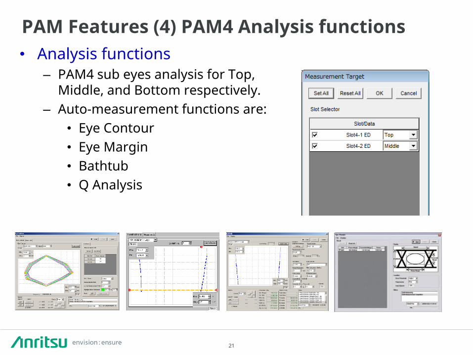
• Analysis functions – PAM4 sub eyes analysis for Top,
Middle, and Bottom respectively. – Auto-measurement functions are:
• Eye Contour • Eye Margin • Bathtub • Q Analysis
PAM Features (4) PAM4 Analysis functions

22
PAM Features (5) Typical waveforms
28.1 Gbaud Rate 25.78125 Gbaud Rate
Conditions Input: 3.5 Vp-p, 1.75 Vp-p, PRBS31 Output: 832 mVp-p, 170 mV/div, 10.0 ps/div

23
28G/32G PPG Specifications Item Specification Operating Bit Rate 2.4 to 28.1 Gbit/s
2.4 to 32.1 Gbit/s (Option) Data Output
Number of Outputs MU183020A 1ch 2 ports (Data/xDdata) (Option) 2ch 4 ports (Data1/xData1, Data2/xData2) (Option) MU183021A 4ch 8 ports (Data1/xData1, Data2/xData2, Data3/xData3, Data4/xData4)
Amplitude 500 mV to 2.0 Vp-p/2 mV step (Option) 500 mV to 3.5 Vp-p/2 mV step (Option)
Offset –2.0 to +3.3 Voh/1 mV step Crosspoint Adjust 20% to 80%/0.1% step @ 28 Gbit/s, 32 Gbit/s
Clock Output Number of Outputs 1 Amplitude 0.3 Vp-p min. 1.0 Vp-p max.
Frequency Selectable clock of 1/1 or 1/2 of bit rate Data Delay Option
Range –1000 to +1000 mUI/2 mUI step Pattern Generation PRBS 2n-1 ( n = 7, 9, 10, 11, 15, 20, 23, 31), Mark Ratio 1/2, Logic POS/NEG
Programmable DATA 2 to 268,435,456 bits/1 bit step, Mark Ratio 1/2, Logic POS/NEG Aux Outputs Divided Clock, Pattern Sync.

24
Item Specification Operating Bit Rate 2.4 to 28.1 Gbit/s, 2.4 to 32.1 Gbit/s (Option) Data Input Number of Inputs MU183040A/B
1ch 2 ports (Data/xData) (Option) 2ch 4 ports (Data1/xData1, Data2/xData2) (Option) MU183041A/B 4ch 8 ports (Data1/xData1, Data2/xData2, Data3/xData3, Data4/xData4
Input Amplitude/ Sensitivity*
Clock Input Number of Inputs 1 Amplitude 0.3 Vp-p min.,1.0 Vp-p max.
Frequency 1/2 of bit rate Clock Delay Range –1000 to +1000 mUI/2 mUI step
Pattern Detection PRBS 2n-1 ( n = 7, 9, 10, 11, 15, 20, 23, 31) , Mark Ratio 1/2, Logic POS/NEG
Programmable DATA 2 to 268,435,456 bits/1 bit step, Mark Ratio 1/2, Logic POS/NEG Aux Outputs Divided clock, Pattern Sync. Analysis Functions Auto Search, Auto Adjust, Bathtub Jitter, EYE Diagram, EYE Margin, Auto Search PAM
Mode, Q-value measurement, Eye Contour, PAM BER Measurement
28G/32G ED Specifications (1/2)
MU183040B/MU183041B
Input Amplitude* 0.05 Vp-p to 1.0 Vp-p
Sensitivity* EYE Amplitude 15 mVp-p (typ.), ≤25 mVp-p
EYE Height 10 mVp-p (typ.)
* Input amplitude is a range where Auto Adjust function operates. Input sensitivity is the minimum input amplitude which becomes error free.
25
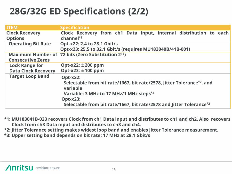
28G/32G ED Specifications (2/2)
*1: MU183041B-023 recovers Clock from ch1 Data input and distributes to ch1 and ch2. Also recovers Clock from ch3 Data input and distributes to ch3 and ch4.
*2: Jitter Tolerance setting makes widest loop band and enables Jitter Tolerance measurement. *3: Upper setting band depends on bit rate: 17 MHz at 28.1 Gbit/s
ITEM Specification Clock Recovery Options
Clock Recovery from ch1 Data input, internal distribution to each channel*1
Operating Bit Rate Opt-x22: 2.4 to 28.1 Gbit/s Opt-x23: 25.5 to 32.1 Gbit/s (requires MU183040B/41B-001)
Maximum Number of Consecutive Zeros
72 bits (Zero Substitution 215)
Lock Range for Data Clock Recovery
Opt-x22: ±200 ppm Opt-x23: ±100 ppm
Target Loop Band Opt-x22: Selectable from bit rate/1667, bit rate/2578, Jitter Tolerance*2, and variable Variable: 3 MHz to 17 MHz/1 MHz steps*3
Opt-x23: Selectable from bit rate/1667, bit rate/2578 and Jitter Tolerance*2

26
Main Applications (Interconnects) (1/2)
• 28G Ultra high speed Interconnect evaluation
– Multichannel Signal Generation Simultaneous Victim and Aggressor signal
generation for multiple channels
– Jitter Tolerance Testing Dual tone SJ/RJ/BUJ/SSC Jitter Tolerance Measuring small amplitude with high-sensitivity ED SERDES measurement with clock recovery
– Compensate for PCB trace losses Emphasis generation – Crosstalk effect testing Timing control and skew control between
channels

27
Main Applications (Interconnects) (2/2)
• Infiniband FDR(14G) / EDR(26G) AOC Evaluation
– 8ch (4ch end-to-end) BER 8ch simultaneous testing
Measuring small swing signal with high- sensitivity ED
– Crosstalk effect test Timing control and skew control between channels – Jitter Tolerance test for CDR SJ/RJ/BUJ/SSC Jitter Tolerance – Output waveform test TJ/DJ/RJ/Bathtub Jitter,
EYE Contour (BER contour mask) analysis
Quad RX CDR
Quad TX CDR
Quad RX CDR
Quad TX CDR

28
Main Applications (CFP2/CFP4)
• CFP2/CFP4 Evaluation
• Crosstalk effect test Timing control and skew control between channels • 25 x 4λ BER All-in-one 4ch simultaneous testing
Measuring small swing signal with high-sensitivity ED • EAM Direct drive 3.5 Vp-p Data out, variable Crosspoint • Jitter Tolerance test for CDR SJ Jitter Tolerance (MU181000 with jitter option can
generate SJ)

29
Main Applications (DP-QPSK, DQPSK) • 32G DP-QPSK Evaluation
• DQPSK Evaluation
- Pre-coding signal generation Synchronized DP-QPSK, DQPSK signal - Optical output waveform optimization Crosspoint adjustment - Timing control between channels Precision data delay - Modulator input level tolerance 3.5 Vp-p Data out, variable Amplitude

30
Multi-channel SQA Solution
56G / 64G Solution

31
MP1861A 56G/64G bit/s MUX
MP1862A 56G/64G bit/s DEMUX
Standard Configurations
MP1800A Max. 6 slot
MP1861A MP1862A
56G/64G Jitter BERT
32G PPG 2ch
Synthesizer (2 Slots)
Jitter Generator (2 Slots)
56G/64G 2ch BERT 56G/64G 4ch BERT (2 box)
4Port Synthesizer
(2 Slots)
32G ED 2ch
64G MUX
64G DEMUX
32G ED 4ch or
32G ED 2ch x 2
4Port Synthesizer
(2 Slots)
64G MUX
64G MUX
64G DEMUX
64G DEMUX
64G MUX
64G MUX
64G MUX
64G MUX
32G PPG 4ch or
32G PPG 2ch x 2
32G PPG 4ch or
32GPPG 2ch x 2
64G DEMUX
64G DEMUX
64G DEMUX
64G DEMUX
32G ED 4ch or
32G ED 2ch x 2
32G ED 4ch or
32G ED 2ch x 2
32G PPG 4ch or
32G PPG 2ch x 2
J1646A Passive Equalizer 6dB (V connector)
Module Lineup

32
• Low-Jitter, High-quality Waveform MUX
50 Gbit/s, 3.5 Vp-p Output Waveform (MP1861A-013)
Features (1) Waveform Quality

33
• High-sensitivity DEMUX Sensitivity: 25 mV (typ.) (56.2 Gbit/s, single-end, EYE Height, PRBS31)
≤40 mV (56.2 Gbit/s, single-end, EYE Height, PRBS31) 30 mV (typ.) (64.2 Gbit/s, single-end, EYE Height, PRBS31)
• Passive equalizer Put passive equalizer upstream of MP1862A 56/64G bit/s DEMUX Compensate transmission path losses, recovery of EYE Opening then possible to
measure BER and execute jitter tolerance
-20
-15
-10
-5
0
0 10 20 30 40 50
S21
[dB
]
Frequency[GHz]
J1646A Passive Equalizer 6dB S21
J1646A
Before
After
※70 mV/div
※50 mV/div
Features (2) Rx Sensitivity and Equalizer

34
• Full jitter components generation: Dual tone SJ, RJ, BUJ, SSC, Half Period Jitter • Automatic jitter tolerance measurements
SJ up to 2000 UI or 0.55 UI high-frequency SJ at 250 MHz (at 56.2Gbps). Low intrinsic jitter: 275 fs rms. (typical).
Generate Various types of jitters
Sine Wave Jitter (SJ) Random Jitter (RJ) Bounded Uncorrelated
Jitter (BUJ) Half Period Jitter (Even/Odd Jitter)
Jitter Generation Mask MX181500A Jitter/Noise Tolerance
Test Software
Features (3) Jitter generation and tolerance test

35
• 4ch Synchronization in one mainframe Ultra high speed synchronized data streams up to 4ch MP1861A 56G /
64G MUX by one MP1800A.
• Crosstalk Tests
Installing MUX Data Delay option offers independent phase control for each channel.
High accurate phase delay setting in 4mUI steps.
Features (4) Synchronous operation

36
Bathtub Jitter Measurement
EYE Diagram Measurement
EYE Margin Measurement
Features (5) Various analysis functions

37
• Burst Signal Tests Supports application evaluation using burst signals, such as optical
circulation loop test Burst disable time up to 1uS (Typical)
• Max 512 Mbit/ch Programmable Data Pattern
Generates any pattern for applications, such as CJTPAT, CJPAT, K28.5
• Pseudorandom Patterns (PRBS) 2 n –1 (n = 7, 9 , 10 , 11 , 15 , 20 , 23 , 31)
• Zero Substitution Patterns
Suitable for clock recovery contiguous 1s and 0s tolerance testing
• Mixed Patterns
Features (6) Various data patterns

38
MP1861A 56G/64G bit/s MUX Bit Rate 8 to 56.2 Gbit/s
8 to 64.2 Gbit/s (MP1861A-001) No. of Channels 1ch, Up to 4ch parallel synchronization by connecting to MP1800A Amplitude 0.5 to 2.5 Vp-p(≤56.2 Gbit/s, MP1861A-011)
1.0 to 2.5 Vp-p(>56.2 Gbit/s, MP1861A-011) 0.5 to 3.5 Vp-p(≤56.2 Gbit/s, MP1861A-013) 1.0 to 3.5 Vp-p(>56.2 Gbit/s, MP1861A-013)
Intrinsic Random Jitter
RJ = 200 fs rms(typ.)
Half Period Jitter 20 Steps
MP1862A 56G/64G bit/s DEMUX Bit Rate 8 to 56.2 Gbit/s
8 to 64.2 Gbit/s (MP1861A-001) No. of Channels 1ch, Up to 4ch parallel synchronization by connecting to MP1800A Amplitude 0.125 to 1.0 Vp-p Sensitivity 25 mV (typ.), ≤40 mV (EYE height, PRBS31, single-ended)
56G/64G bit/s MUX/DEMUX specifications

39
• 56 Gbit/s Band High Speed Semiconductor Chip Measurements
- 56 / 64 Gbit/s BER Measurements For SERDES, Clock Data Recovery(CDR), etc. - Jitter Tolerance Tests Supports dual tone SJ, RJ, BUJ, SSC, etc.,
Jitter Tolerance tests for CEI-56G - Input Sensitivity Tests Wide variable amplitude range
0.5 to 3.5 Vpp (56G, with installed MP1861A-013 option) - Bathtub Jitter Measurements TJ / RJ / DJ separation
Main Applications (Interconnect)

40
- 200 GbE, 56G × 4 lane evaluation Supports EML and optical module evaluations for 200G / 400GbE
- EML evaluation Direct EML driving using variable output function up to 3.5 Vp-p
- Confirming skew and crosstalk effects Pattern Sync and Variable Phase functions support easy verification of Rx device skew tolerance, crosstalk effects
- Auto search functions Data and Clock phase auto alignment
Main Applications (Transmitter)

41
Multi-channel SQA Solution
56G / 64GBaud PAM4 Solution

42
G0374A 64Gbaud PAM4 DAC ・Wide Operating Range: DC to 64 Gbaud ・Generates 64 Gbaud PAM4 signal using half rate 32 Gbit/s x 4 input signals ・1.4 Vp-p (differential, Typ.) output ・Amplitude, duty and Upper / Lower / Middle amplitude ratio control by manual ・Low output Jitter performance of only 300 fs (rms) ・NRZ, PAM4 signal control and jitter addition
Front View Rear View
64Gbaud PAM4 DAC features

43
4ch 32G PPG MU183020A 32G 2ch PPG x2
MU181000A/B Synthesizer
MP1800A Signal Quality Analyzer
DUT or Scope
32Gbit/s Data1A,B(MSB)
32 Gbit/s Data0A,B(LSB)
64 Gbaud PAM4 Data output
32 GHz Clock input
G0374A 64Gbaud PAM4 DAC
64Gbaud PAM4 generation block diagram

44
PAM4 Output Waveforms (41 V -6 ATT +3 4 V V50 Adapter + 70-GHz Band Oscilloscope)
NRZ Output Waveforms (41 V -6 ATT +3 4 V V50 Adapter + 70-GHz Band Oscilloscope)
64 Gbaud 56 Gbaud 28 Gbaud
64 Gbaud 56 Gbaud
Typical waveform from 64Gbaud PAM4 DAC

45
Data3
Data1
Data4
Data2 MU18302xA
MU181500B Jitter generation
MU181000A/B
Data Cablex4
Clock Cable
G0374A 64Gbaud PAM4 DAC has jitter transparency. So jitter stress test is possible on top of PAM4 signal.
Block diagram for jitter injection
Recommended cables: Data Cables 80 cm (J1612A x4) Clock Cable 130 cm (J1611A)
G0374A 64Gbaud PAM4 DAC

46
MP1862A 64G DEMUX MU183040B
32G 2ch ED
MP1862A measures 3 sub eyes BER respectively.
MU183020A 32G 2ch PPG x2
MU181000B Synthesizer
MP1800A Signal
Quality Analyzer
28 Gbit/s Data1A,B(MSB)
28 Gbit/s Data0A,B(LSB)
64 Gbaud PAM4
28 GHz Clock
DUT
・Support 56Gbaud PAM4 BER measurement with PRBS15
56Gbaud PAM4 BER measurement
G0374A 64Gbaud PAM4 DAC

47
Multi-channel SQA Solution
High Speed Serial Bus Solution - Thunderbolt Gen3 - USB3.1 Gen1 / Gen2 - PCIe Gen4

48
Agenda
1. TBT solution 2. USB solution 3. PCIe solution

49
What is Thunderbolt (TBT)? - 10.3125 Gbps for Gen1 & Gen2, 2 x 20.625 Gbps for Gen3. - Integrated multiple applications through ALT mode (TBT, USB, DP) - Power delivery up to 100 W
Anritsu Solution - MP1800A SQA is the first authorized BERT by Intel. - MS46322A VNA is also authorized by Intel. - Anritsu collaborate with GRL (Granite River Labs Inc.) to provide automated solution. - GRL is one of the authorized test house for TBT by Intel. GRL: HQ in Santa Clara US. - High repeatability one button calibration and Rx test based on Thunderbolt CTS (Compliance Test Specification).
Thunderbolt Overview

50
MP1800A #1 Recommended Test Equipment

51
Host/Device RX (DUT)
TBT Plug PPG Emphasis
Crosstalk source SJ RJ SSC
TP2: Case1
Host/Device RX (DUT)
TBT Plug PPG Emphasis
Crosstalk source SJ RJ SSC TP3EQ: Case2
PCB -3.5dB@5GHz
Cable (2m) -12dB@5GHz
CM injection
CM injection
Thunderbolt Receiver tolerance test setup

52
Test case 1 (TP2)
Thunderbolt Receiver tolerance calibration setup
Real time scope

53
Test case 2 (TP3EQ)
Thunderbolt Receiver tolerance calibration setup
Real time scope

54
Thunderbolt calibration procedure (1/2) 1. Set inner eye amplitude (700 mVpp differential)
2. Find minimum DDJ from 16 presets for emphasis
3. CM noise phase adjustment

55
4. CM noise During CM calibration, MP1825B output set to off. After calibrated CM, CM should be turn off.
5. RJ calibration Only RJ set to on during RJ calibration.
6. SJ calibration Calibrate at 5 different SJ frequencies Only SJ set to on during SJ calibration.
7. TJ calibration Set calibrated CM, RJ and SJ value on. Final value should be adjusted by RJ value. Adjusted TJ values should be saved respectively.
Thunderbolt calibration procedure (2/2)

56
Jittered Data
J1510A
MG3740A
DUT
MP1800A 32G PPG MP1825B
4tap emphasis
Jittered Clock
K241C
J1510A K261 Type-C
Cable
Control PC Including Alpine Ridge
Host
K261
Alpine Ridge
DP Device
Receptacle Fixture
Skew Matched Pair Cables
Type-C Cable 10G: 1.8 m 20G: 0.5 m
K-SMP Adapter
Data
xData
Aggressor 1/8 Clock
800 mVp-p, Diff.
TBT3 Rx test configuration at TP3EQ

57
Thunderbolt automated test solution by GRL
Target values for each settings
Calibration & Test item Test point settings

58
Agenda
1. TBT solution 2. USB solution 3. PCIe solution

59
USB 3.1 Gen1 & Gen2 Solution
What is USB3.1? - New connector: Type C - Two speed (Gen1: 5Gbps, Gen2: 10Gbps) - Part of Intel TBT chip (Alpine Ridge) Anritsu solution - Link Generation (MX183000A) - Automated calibration and JTOL (GRL) - USB Adaptor with BER measurement function Features Simple, easy Go / No Go test Support USB3.1 Gen1 & Gen2 Host / Device receiver test Full automatic calibration and test in loopback mode Receiver test with compliance test pattern

60
Test procedure
1. Calibrating stressed waveform by GRL software
2. Setting DUT in loopback mode by MX183000A software LFPS (Low Frequency Periodic Signaling) Low Freq (10M-20Mbps) communication between USB devices. Change USB internal state (LTSSM) to loopback For Rx tolerance test, DUT must be in loopback state. MX183000A can control state transition automatically.
3. BER measurement by external USB adaptor

61
USB 3.1 Gen1&Gen2 loop back link generation MX183000A

62
USB 3.1 Gen1&Gen2 Calibration software (GRL)

63
LFPS RX+
LFPS TX+
GATING
AUX
MP1825B Emphasis
ARTEK USB TEST ADAPTOR
Dataout +
Dataout -
LFPS TX-
LFPS RX- LFPS RX
J1510A Pick OFF Tee
(Direct Connection)
J1349A(0.3m)
J1551A
(0.8m Phase
matched Pair)
J1343A(1.0m)
J1343A(1.0m)
J1343A(1.0m)
J1615A (Pair Cable
0.8m for Data, 1.3m for clock)
Test Fixture
for DUT
Data In
Clock In
J1349A(0.3m)
J1551A (0.8m Phase matched Pair)
MP1800A, MX183000A MU183020A 32G PPG
Data out +
Clock out
Gating out
AUX out+
AUX in
(for LPFS detection)
USB compliance test block diagram
Ethernet
Analyzing BER

64
Gen2 Test points Confirm error free at 1E-10 (Tentative) SJ: 17 ps +/- 10% at 50 MHz 17 ps +/- 10% at 7.5 MHz 37 ps +/- 10% at 4.0 MHz 87 ps +/- 5% at 2.0 MHz 203 ps +/- 5% at 1.0 MHz 476 ps +/- 5% at 500 MHz Gen1 Test points Confirm error free at 1E-10 SJ: 40 ps +/- 10% at 33 MHz 40 ps +/- 10% at 20 MHz 40 ps +/- 10% at 10 MHz 40 ps +/- 10% at 4.9 MHz 100 ps +/- 5% at 2.0 MHz 200 ps +/- 5% at 1.0 MHz 400 ps +/- 5% at 500 kHz
Test points
MX183000A - BER measurement - Pass / Fail display

65
Agenda
1. TBT solution 2. USB solution 3. PCIe solution

66
PCI Express Solution Anritsu target market for PCIe - Multi application interface high speed semiconductor
PCIe + 100GbE, PCIe + Thunderbolt, PCIe + Thunderbolt + USB3.1 Anritsu solution - Based on PCIe Gen4 Base specification revision 0.5 - Link capability (MX183000A) and Automated Cal & JTOL (GRL)
BUS/Backplane : PCIe-Gen3 to Gen4
Inter equipment - Ethernet - InfiniBand 10Gbps 100Gbps (4x25G)
Add-in Card
Chip

67
Different PCIe architecture
PCIe Device A
PCIe Device B
Ref clock
PCIe Channel
PCIe Device A
PCIe Device B
Ref clock
PCIe Channel
Case 1: Common Clock Architecture Case 2: Data Clocked Architecture
PCIe Device A
PCIe Device B
Ref clock #1
PCIe Channel
Case 3: Separate Ref Clock Architecture
Ref clock #2
Connector Cable
Cable
Ref ck for Tx

68
Two improvements will be implemented (1/2)
■Different frequency clock between two PCIe devices
PCIe Device A
PCIe Device B
Ref clock
PCIe Channel
Data Clocked Architecture
Cable Ref ck for Tx
PCIe Device A
PCIe Device B
Ref clock #1
PCIe Channel
Separate Ref Clock Architecture
Ref clock #2
■PCIe TX generates SKP ordered set randomly / automatically
Also in loopback mode, TX generates SKP into transmitting data. ED incoming data is different from PPG transmitted data Future Anritsu solution will support “SKP ordered set ”.
SKP ordered set

69
SSC: Change carrier frequency slowly to save EMI PCIe: 5000 ppm, 33 kHz, Triangle waveform
ppm
kHz
Future Anritsu solution will support SSC data Error Detection
Carrier frequency deviation
SSC (Spread Spectrum Clocking) Two improvements will be implemented (2/2)

70
PCIe Device A
PCIe Device B
Ref clock
PCIe Channel
Common Clock Architecture
Current Anritsu PCIe Solution
Anritsu+GRL-PCIE4-BASE-RXA Key Features Totally Automated PCIe 4.0 Rx Base Spec Test using Anritsu equipment Perform Receiver Jitter Tolerance test at the push of a button Reduce technical risk using an industry-accepted calibration methodology Achieve consistent results with rapid test execution
Current Anritsu Solution without SSC condition

71
PCIe Gen4 Calibration points

72
PCIe base spec calibration test setup for TP1
Real time scope

73
PCIe base spec calibration test setup for TP2
Real time scope

74
PCIe Gen4 Base spec calibration procedure
1. Emphasis eye amplitude calibration 2. De-emphasis and Pre-shoot calibration 3. RJ, SJ calibration 4. ISI loss calibration 5. CMI, DMI calibration 6. Stressed eye calibration

75
PCIe base spec receiver tolerance test setup
76
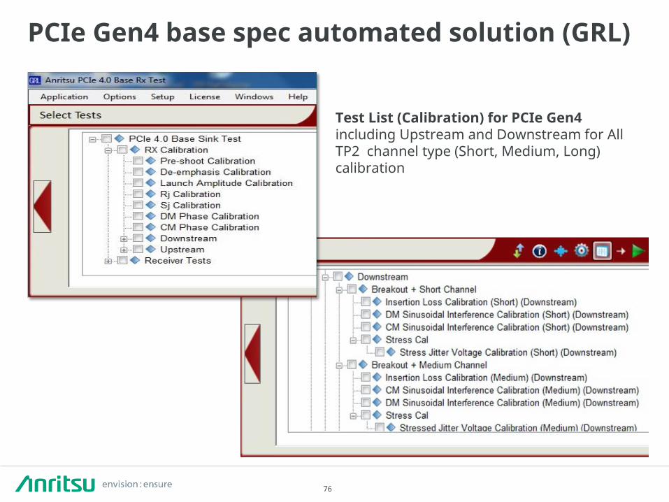
PCIe Gen4 base spec automated solution (GRL)
Test List (Calibration) for PCIe Gen4 including Upstream and Downstream for All TP2 channel type (Short, Medium, Long) calibration

77
PCIe Gen4 base spec automated solution (GRL)
1) Select Rx Test
2) Run Tests (Go / No Go at test points)
3) Generate Report

78
PCIe Gen1 to 4 loop back link generation (Anritsu) MX183000A
- Sets DUT in loop back mode - PCIe Gen 1 to Gen4 - Jitter tolerance “margin” test

79
Anritsu PCIe Solution operation procedure
1. Calibrate waveform by GRL SW
2. Set DUT in loop back mode
3. Jitter tolerance test for two options AAA) Anritsu margin test BBB) GRL Go / No Go test

80
Anritsu / GRL PCIe Solution features GRL-PCIE4-BASE-RXA Key Features Automate PCIe 4.0 Rx Base Spec Test using Anritsu equipment Perform Receiver Jitter Tolerance test at the push of a button Reduce technical risk using an industry-accepted calibration methodology Achieve consistent results with rapid test execution
MX183000A Key Features Establish loop back mode for PCIe Gen1 to Gen4 Jitter tolerance margin test Supporting also USB3.1 Gen1 (5Gbps) & Gen2 (10Gbps)
Application Specifications • Data Rates: 16 GT/s • Supported Receiver Test: Common Clock Architecture without SSC • This application is compatible with:
– Keysight 32 GHz Oscilloscope (DSAX or newer series) – Anritsu MP1800A Signal Quality Analyzer – Artek CLE-1000 A2 Variable ISI Channel

81
A p p e n d i x

82
History of Anritsu BERTS
2000 – 2005 ~ 1999
43.5 Gbit/s BERT System
43.5 Gbit/s MUX/DEMUX
MP1800A Flexible
architecture
3 Gbit/s/1990
3.2 Gbit/s/1998 1600+ Sales
12.5 Gbit/s x 4ch/2001
12.5 Gbit/s x 4ch PPG/1995
12.5 Gbit/s/1994
10 Gbit/s/1990
Small Remote BOX 56 Gbit/s MUX/DEMUX
≤43.5 Gbit/s
≤12.5 Gbit/s
≤3.2 Gbit/s MP2100B BERTWave 10 Gbit/s BERT&Scope
Keep evolving !
2005 – 2010 Today to future
Built-in Scope
Jitter Analysis
>43.5 Gbit/s
1977 2 Gbit/s/1977
Broadband

83
Signal Quality Analyzer MP1800A Series
BERTWave MP2100B Series
Solution: 10/25/32/64 Gbit/s device tests Features: Easy support for latest applications by adding
functions matching customers’ TTM due to flexible/scalable modular architecture
Unique Jitter and Emphasis functions, high sensitivity, built-in Clock Recovery, and PAM signal generation for 32G applications
Solution: 10 Gbit/s BER tests, EYE Pattern measurements Features: All-in-one solution supporting BERT and Scope BERT expansion up to 4 channels Fast remote control and high-speed Eye Mask tests Compact design (180 mm deep)
Anritsu Product Lineup
Manufacturing
R&D Cutting
Edge
Design Verification
Test

2016-8 MG No. MP1800_32G-E-L-1-(6.00)