much more than technology passive das solutions more than technology passive das solutions site...
TRANSCRIPT

Much More Than Technology
Passive DAS Solutions
SITE SOLUTIONS

2
Rosenberger Site Solutions – Much More Than Technology
The Rosenberger Site Solutions Group designs, manufactures and provides solutions for the wireless infrastructure market. Our products and systems offer innovative and leading-edge designs with a focus on high performance and quality. Having an efficient network implementation in mind, we focus on total site kitting, logistics and delivery time leading to reduced cost of ownership. Globally present, the Rosenberger Site Solutions Group offers extensive local support making Rosenberger Site Solutions a partner instead of just a supplier.
3Rosenberger Site Solutions GmbH | www.rosenberger.com/siso
The Rosenberger Online Catalog contains the current standard product range with specific details, including data sheets, assembly instructions, and panel piercings.
www.rosenberger.com/ok
Company 04
Quality and the Environment 06
Competencies & Technology 08
Passive Components 10
Antennas 18
Connectors 20
Tools 23
Jumper Cables 25
Coax Cables 27
Test & Measurement 40
Multi-functional PIM Site Analyzer 46
Index 50
Contents

4
Home of Innovation
A global network of Rosenberger R&D, manufacturing facilities and sales offices provides innovation, optimized cost structure and outstanding local customer service.
The Rosenberger headquarters located in Fridolfing in the southeast part of Bavaria, Germany

5Rosenberger Site Solutions GmbH | www.rosenberger.com/siso
Company ProfileRosenberger is one of the world's leading manufacturers of impedance-controlled and optical-connectivity solutions. We provide these solutions in high-frequency, high- voltage, and fiber-optic technology for mobile communication networks, data centers, test & measurement applications, automotive electronics, as well as high- voltage contact systems, medical electronics and aerospace engineering.
A global network of R&D, manufacturing and assembly locations provides innovation, optimized cost structure and excellent customer services. A total of around 8,500 employees are involved in the development, production, and distribution of our products.
Rosenberger Group
Europe Germany: Fridolfing, Augsburg, Laufen, Radeberg Austria: Timelkam Hungary: Jászárokszállás, Jászberény, Taksony Denmark: Birkerød Sweden: Kista, Solna, Ytterhogdal Spain: Madrid
North America USA: RNA Plano, RNA Akron, RNA Pennsauken,
RSS Lake Charles
South America Brazil: Caçapava – São Paulo Chile: Santiago
Asia China: Beijing, Kunshan, Dongguan India: Manesar, Goa
Company

6
Ensuring the optimum quality of products and services and taking responsibility for our environment are funda-mental elements of Rosenberger's corporate philosophy. Our approach to ensuring quality covers more than just the optimization of parts and products – it also includes the continuous improvement of all company processes: from product development, planning, procurement, production, sales, and logistics right through to environ-mental policy. To summarize, we want to offer maximum benefits for our customers all over the world.
We aim to act in an environmentally conscious manner, use materials economically, protect natural resources, recycle, and ensure energy efficiency.
As we have continuously improved our processes and consistently applied our quality management systems, we have been awarded many certificates.
Certifications ISO / TS 16949 DIN EN 9100 ISO 9001 ISO 14001 DaKKs accreditation according to DIN EN ISO 17025
Rosenberger has won a number of prestigious quality awards and prizes from several renowned customers and organizations for achieving its quality and environ mental objectives.

7Rosenberger Site Solutions GmbH | www.rosenberger.com/siso
Our Promise to You. And to Quality and the Environment.
The quality of our products, solutions, and services is an essential part of our corporate strategy.
Quality and the Environment
8
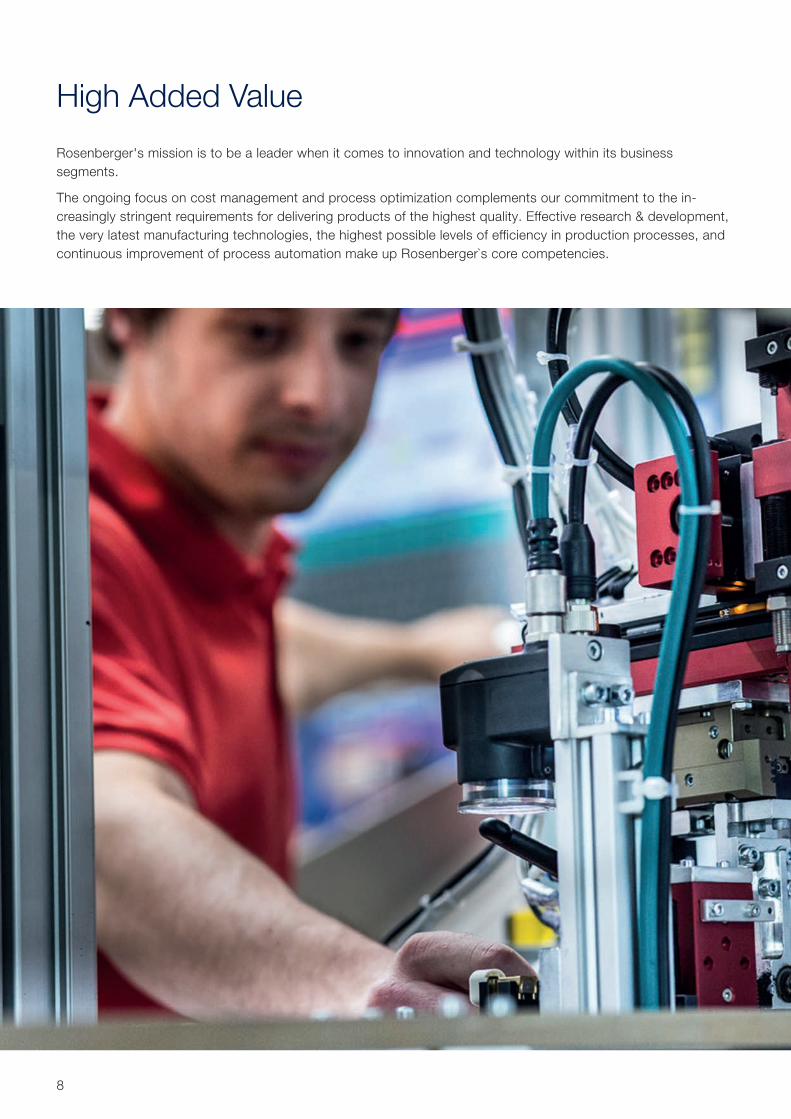
High Added Value
Rosenberger's mission is to be a leader when it comes to innovation and technology within its business segments.
The ongoing focus on cost management and process optimization complements our commitment to the in-creasingly stringent requirements for delivering products of the highest quality. Effective research & development, the very latest manufacturing technologies, the highest possible levels of efficiency in production processes, and continuous improvement of process automation make up Rosenberger`s core competencies.
9Rosenberger Site Solutions GmbH | www.rosenberger.com/siso
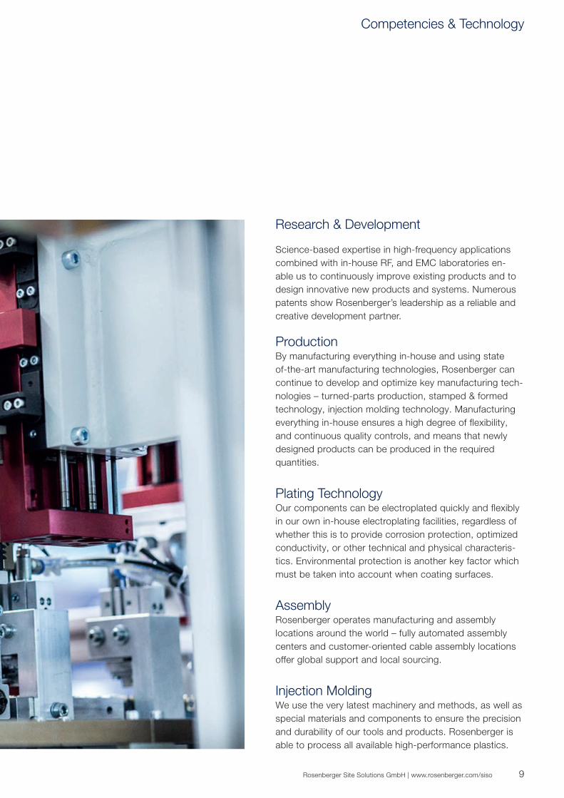
Research & Development
Science-based expertise in high-frequency applications combined with in-house RF, and EMC laboratories en-able us to continuously improve existing products and to design innovative new products and systems. Numerous patents show Rosenberger’s leadership as a reliable and creative development partner.
ProductionBy manufacturing everything in-house and using state of-the-art manufacturing technologies, Rosenberger can continue to develop and optimize key manufacturing tech-nologies – turned-parts production, stamped & formed technology, injection molding technology. Manufacturing everything in-house ensures a high degree of flexibility, and continuous quality controls, and means that newly designed products can be produced in the required quantities.
Plating TechnologyOur components can be electroplated quickly and flexibly in our own in-house electroplating facilities, regardless of whether this is to provide corrosion protection, optimized conductivity, or other technical and physical characteris-tics. Environmental protection is another key factor which must be taken into account when coating surfaces.
AssemblyRosenberger operates manufacturing and assembly locations around the world – fully automated assembly centers and customer-oriented cable assembly locations offer global support and local sourcing.
Injection MoldingWe use the very latest machinery and methods, as well as special materials and components to ensure the precision and durability of our tools and products. Rosenberger is able to process all available high-performance plastics.
Competencies & Technology

10
Passive Components for DAS Systems
With the development of modern wireless communication technologies, mobile communications networks are deployed requiring wideband universal passive components. Rosenberger supplies a complete range of passive components for wireless Distributed Antenna Systems (DAS) for in-building coverage such as splitters, combiners, termination loads, attenuators, and antennas.
Easy to install, Rosenberger DAS components ensure reliable, high quality and low PIM operation.
11Rosenberger Site Solutions GmbH | www.rosenberger.com/siso
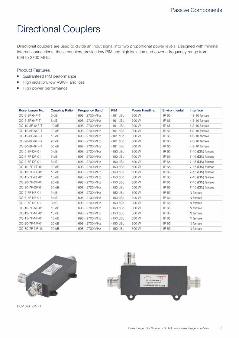
Directional Couplers
Directional couplers are used to divide an input signal into two proportional power levels. Designed with minimal internal connections, these couplers provide low PIM and high isolation and cover a frequency range from 698 to 2700 MHz.
Product Features Guaranteed PIM performance High isolation, low VSWR and loss High power performance
Rosenberger No. Coupling Ratio Frequency Band PIM Power Handling Environmental Interface
DC-6-8F-64F-T 6 dB 698 - 2700 MHz -161 dBc 300 W IP 65 4.3-10 female
DC-8-8F-64F-T 8 dB 698 - 2700 MHz -161 dBc 300 W IP 65 4.3-10 female
DC-10-8F-64F-T 10 dB 698 - 2700 MHz -161 dBc 300 W IP 65 4.3-10 female
DC-12-8F-64F-T 12 dB 698 - 2700 MHz -161 dBc 300 W IP 65 4.3-10 female
DC-15-8F-64F-T 15 dB 698 - 2700 MHz -161 dBc 300 W IP 65 4.3-10 female
DC-20-8F-64F-T 20 dB 698 - 2700 MHz -161 dBc 300 W IP 65 4.3-10 female
DC-30-8F-64F-T 30 dB 698 - 2700 MHz -161 dBc 300 W IP 65 4.3-10 female
DC-5-8F-DF-01 5 dB 698 - 2700 MHz -150 dBc 300 W IP 65 7-16 (DIN) female
DC-6-7F-DF-01 6 dB 698 - 2700 MHz -150 dBc 500 W IP 65 7-16 (DIN) female
DC-8-7F-DF-01 8 dB 698 - 2700 MHz -150 dBc 500 W IP 65 7-16 (DIN) female
DC-10-7F-DF-01 10 dB 698 - 2700 MHz -150 dBc 500 W IP 65 7-16 (DIN) female
DC-13-7F-DF-01 13 dB 698 - 2700 MHz -150 dBc 500 W IP 65 7-16 (DIN) female
DC-15-7F-DF-01 15 dB 698 - 2700 MHz -150 dBc 500 W IP 65 7-16 (DIN) female
DC-20-7F-DF-01 20 dB 698 - 2700 MHz -150 dBc 500 W IP 65 7-16 (DIN) female
DC-30-7F-DF-01 30 dB 698 - 2700 MHz -150 dBc 500 W IP 65 7-16 (DIN) female
DC-5-7F-NF-01 5 dB 698 - 2700 MHz -150 dBc 300 W IP 65 N female
DC-6-7F-NF-01 6 dB 698 - 2700 MHz -150 dBc 300 W IP 65 N female
DC-8-7F-NF-01 8 dB 698 - 2700 MHz -150 dBc 300 W IP 65 N female
DC-10-7F-NF-01 10 dB 698 - 2700 MHz -150 dBc 300 W IP 65 N female
DC-13-7F-NF-01 13 dB 698 - 2700 MHz -150 dBc 300 W IP 65 N female
DC-15-7F-NF-01 15 dB 698 - 2700 MHz -150 dBc 300 W IP 65 N female
DC-20-7F-NF-01 20 dB 698 - 2700 MHz -150 dBc 300 W IP 65 N female
DC-30-7F-NF -01 30 dB 698 - 2700 MHz -150 dBc 300 W IP 65 N female
DC-10-8F-64F-T
Passive Components
12
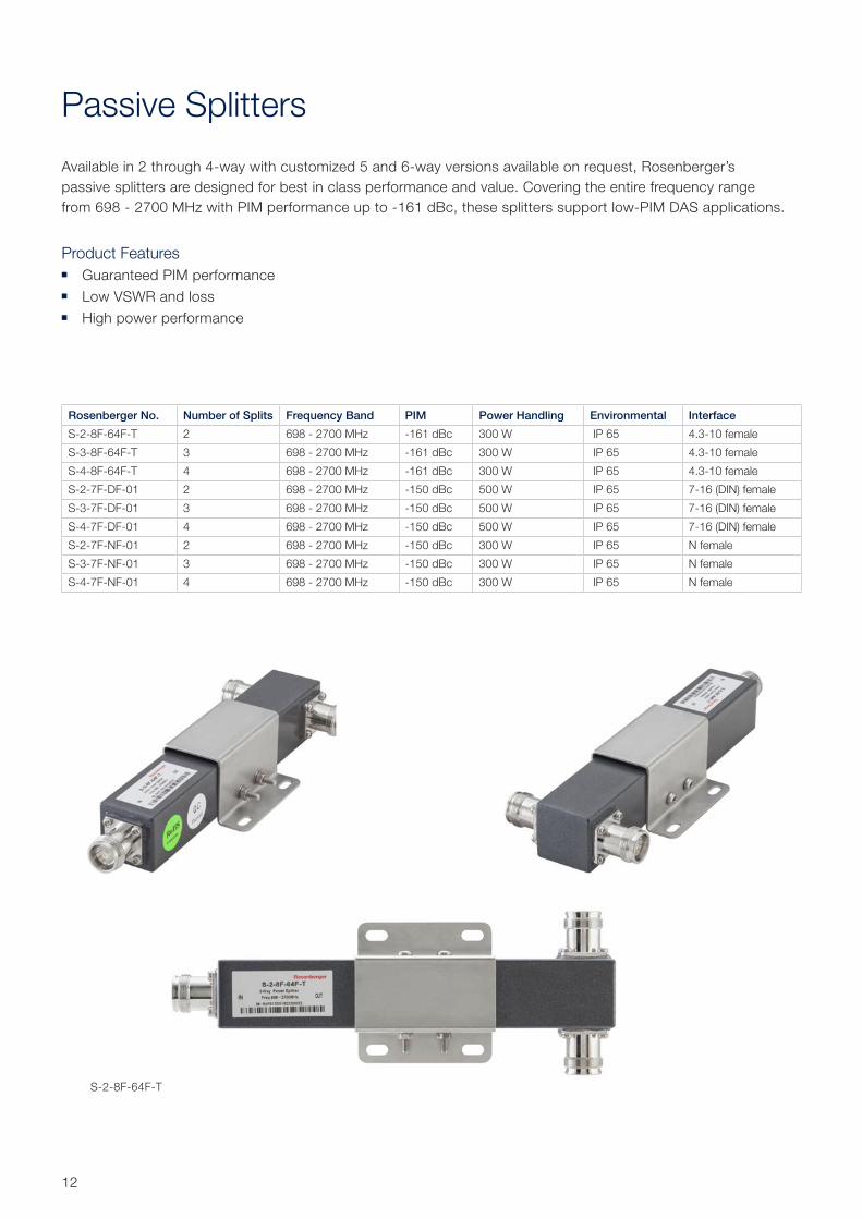
Passive Splitters
Available in 2 through 4-way with customized 5 and 6-way versions available on request, Rosenberger’s passive splitters are designed for best in class performance and value. Covering the entire frequency range from 698 - 2700 MHz with PIM performance up to -161 dBc, these splitters support low-PIM DAS applications.
Product Features Guaranteed PIM performance Low VSWR and loss High power performance
Rosenberger No. Number of Splits Frequency Band PIM Power Handling Environmental Interface
S-2-8F-64F-T 2 698 - 2700 MHz -161 dBc 300 W IP 65 4.3-10 female
S-3-8F-64F-T 3 698 - 2700 MHz -161 dBc 300 W IP 65 4.3-10 female
S-4-8F-64F-T 4 698 - 2700 MHz -161 dBc 300 W IP 65 4.3-10 female
S-2-7F-DF-01 2 698 - 2700 MHz -150 dBc 500 W IP 65 7-16 (DIN) female
S-3-7F-DF-01 3 698 - 2700 MHz -150 dBc 500 W IP 65 7-16 (DIN) female
S-4-7F-DF-01 4 698 - 2700 MHz -150 dBc 500 W IP 65 7-16 (DIN) female
S-2-7F-NF-01 2 698 - 2700 MHz -150 dBc 300 W IP 65 N female
S-3-7F-NF-01 3 698 - 2700 MHz -150 dBc 300 W IP 65 N female
S-4-7F-NF-01 4 698 - 2700 MHz -150 dBc 300 W IP 65 N female
S-2-8F-64F-T

13Rosenberger Site Solutions GmbH | www.rosenberger.com/siso
Hybrid Combiners
Available in broadband and band-specific versions, these hybrid combination allow for the combining of multiple technologies within the same band. The excellent PIM performance of up to -161 dBc, low insertion loss, and low VSWR make these combiners an excellent choice for DAS applications.
Product Features Low PIM and high isolation, low VSWR and insertion loss High reliability Simple installation
Rosenberger No. Number of Splits in/out
Frequency Band PIM Power Handling Environmental Interface
HM-3-8F-64F-T 2/2 698 - 2700 MHz -161 dBc 300 W IP 65 4.3-10 female
HM-6-8F-64F-T 4/4 698 - 2700 MHz -161 dBc 300 W IP 65 4.3-10 female
HM-3-7F-DF-02 2/2 698 - 2700 MHz -150 dBc 500 W IP 65 7-16 (DIN) female
HM-6-8F-DF-01 4/4 698 - 2700 MHz -150 dBc 500 W IP 65 7-16 (DIN) female
HM-3-7F-NF-01 2/2 698 - 2700 MHz -150 dBc 300 W IP 65 N female
HM-6-8F-NF-01 4/4 698 - 2700 MHz -150 dBc 300 W IP 65 N female
HM-3-8F-64F-T
Passive Components

14
Combiners
Rosenberger frequency combiners are deployed in site-sharing or co-siting applications. Suitable for both indoor and outdoor installations, these low-loss combiners are available as single units or for cross-pole antennas as double units. DC blocks can be added as an option.
Product Features Low PIM performance Wall or pole mount High isolation, low VSWR and insertion loss
Rosenberger No. Frequency Band (MHz)* Loss (dB) Return Loss (dB) PIM Power Handling Interface
CB-4-GDWE-64F-01 G, D, W, E ≤ 0.3 ≥ 20 -161 dBc 300 W 4.3-10 female
CB-4-LCAP-64F-02 L, C, A, P ≤ 0.5 ≥ 20 -161 dBc 300 W 4.3-10 female
CB-4-GDWE-DF-08G G, D, W, E ≤ 0.3 ≥ 20 -155 dBc 250 W 7-16 (DIN) female
CB-3-GDU-DF-04 L, D, W ≤ 0.2 ≥ 20 -153 dBc 250 W 7-16 (DIN) female
CB-3-DWE-DF-01 D, W, E ≤ 0.5 ≥ 20 -150 dBc 300 W 7-16 (DIN) female
CB-2-DW-DF-02H-T3 D, W ≤ 0.2 ≥ 20 -160 dBc 250 W 7-16 (DIN) female
CB-2-LH-DF-01 L, HL ≤ 0.2 ≥ 19 -150 dBc 500 W 7-16 (DIN) female
CB-2-FM-DF-01 F, M ≤ 0.5 ≥ 19 -150 dBc 300 W 7-16 (DIN) female
CB-2-LH-NF-01 L / H ≤ 0.5 ≥ 20 -150 dBc 300 W N female
* Letter * Frequency Band
HL 380 -960 MHz
LT 698 - 787 MHZ
LL 698 - 806 MHz
L 790 - 960 MHz
F 806 - 2170 MHz
C 824 - 894 MHz
G 698 - 960 MHz
D 1710 - 1880 MHz
A 1710 - 1755 MHz2110 - 2155 MHz
P 1850 - 1990 MHz
W 1920 - 2170 MHz
M 2400 - 2700 MHz
E 2500 - 2700 MHz
H 1710 - 2700 MHz
CB-4-GDWE-64f-01
15Rosenberger Site Solutions GmbH | www.rosenberger.com/siso
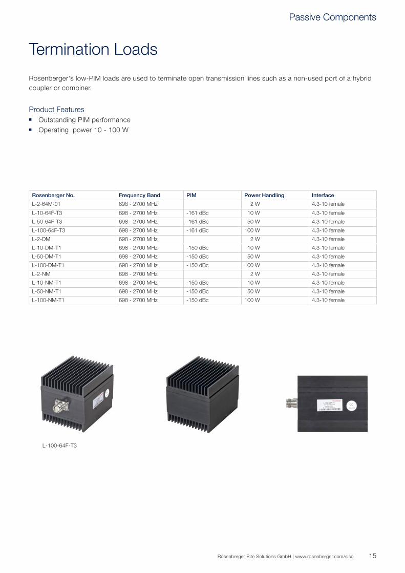
Termination Loads
Rosenberger's low-PIM loads are used to terminate open transmission lines such as a non-used port of a hybrid coupler or combiner.
Product Features Outstanding PIM performance Operating power 10 - 100 W
Rosenberger No. Frequency Band PIM Power Handling Interface
L-2-64M-01 698 - 2700 MHz 2 W 4.3-10 female
L-10-64F-T3 698 - 2700 MHz -161 dBc 10 W 4.3-10 female
L-50-64F-T3 698 - 2700 MHz -161 dBc 50 W 4.3-10 female
L-100-64F-T3 698 - 2700 MHz -161 dBc 100 W 4.3-10 female
L-2-DM 698 - 2700 MHz 2 W 4.3-10 female
L-10-DM-T1 698 - 2700 MHz -150 dBc 10 W 4.3-10 female
L-50-DM-T1 698 - 2700 MHz -150 dBc 50 W 4.3-10 female
L-100-DM-T1 698 - 2700 MHz -150 dBc 100 W 4.3-10 female
L-2-NM 698 - 2700 MHz 2 W 4.3-10 female
L-10-NM-T1 698 - 2700 MHz -150 dBc 10 W 4.3-10 female
L-50-NM-T1 698 - 2700 MHz -150 dBc 50 W 4.3-10 female
L-100-NM-T1 698 - 2700 MHz -150 dBc 100 W 4.3-10 female
L-100-64F-T3
Passive Components

16
Attenuators
Rosenberger offers a wide range of attenuators.
Product Features Guaranteed PIM performance High isolation, low VSWR and loss Rugged aluminum housing for long lasting, reliable performance
Rosenberger No. Frequency Band VSWR PIM Power Handling Interface
A-xx-50-64-T3 698 - 2700 MHz 1.20 -161 dBc 50 W 4.3-10 male to 4.3-10 female
A-xx-100-64-T3 698 - 2700 MHz 1.20 -161 dBc 100 W 4.3-10 male to 4.3-10 female
A-xx-50-D-T1 698 - 2700 MHz 1.20 -150 dBc 50 W 7-16 (DIN) male to 7-16 (DIN) female
A-xx-100-D-T1 698 - 2700 MHz 1.35 -150 dBc 100 W 7-16 (DIN) male to 7-16 (DIN) female
A-xx-50-N-T1 698 - 2700 MHz 1.20 -150 dBc 50 W N male to N female
A-xx-100-N-T1 698 - 2700 MHz 1.35 -150 dBc 100 W N male to N female

17Rosenberger Site Solutions GmbH | www.rosenberger.com/siso
POI – Point of Interface
Rosenberger’s modular POI is a passive system that is used for multiple inputs and outputs. It can combine different operators and systems into the same DAS with high isolation and low PIM interference.
The modular cabinets are easy to modify and update. If the operators upgrade their systems, there is no need to change the whole POI, but just upgrading the relevant modules can solve any problems that might occur. The field installation is very easy because of the "Plug and Play" design between the modular and the POI system.
Product Features Easy upgrade 4.3-10 interface Excellent PIM performance PNP (Plug-and-Play) modular inside
Customized frequency band Better same band isolation Higher power handling
Rosenberger No. Frequency Bands (MHz) Loss (dB)
Isolation Return Loss (dB)
PIM Power Handling
Interface
CB-13-POI-64F-01 iDEN: 806~825 / 851~870 MHzGSM-1: 900~915 / 945~960 MHzGSM-2: 890~900 / 935~945 MHzGSM-3: 880~890 / 925~935 MHzDCS-1: 1710~1715 / 1805~1810 MHz 1735~1740 / 1830~1835 MHzDCS-2: 1760~1785 / 1855~1880 MHzDCS-3: 1715~1720 / 1810~1815 MHz 1740~1760 / 1835~1855 MHz3G-1: 1935.1~1950.1 / 2125.1~2140.1 MHz 1969.9~1974.9 / 2159.9~2164.9 MHz3G-2: 1950.1~1969.9 / 2140.1~2159.9 MHz3G-3: 1920.0~1935.1 / 2110.3~2125.1 MHz 1974.9~1979.7 / 2164.9~2169.7 MHzLTE2600-1: 2500-2520 / 2620-2640 MHzLTE2600-2: 2520-2540 / 2640-2660 MHzLTE2600-3: 2540-2560 / 2660-2680 MHz
≤ 5.5 Same bands: ≥ 33dBDiffer. bands: ≥ 65dB
≥ 18 -155 dBc 100 W 4.3-10 female
Passive Components

18
DAS In-Building Antennas
The Rosenberger broadband in-building antennas are suitable for all indoor distribution systems mainly installed in shopping malls, restaurants, office buildings, or sports facilities.
Product Features Ultra-wideband Indoor Ceiling Mounting Antenna Smooth design Vertical Polarization 2G/3G/LTE Small and compact
Rosenberger No. Frequency Band Antenna Type PIM Connector Product
SL S4935i 698 - 6000 MHz Ceiling mount -153 dBc 4.3-10 female
SL S5606i 698 - 2700 MHz Ceiling mount, ultra flat -153 dBc 4.3-10 female
SL S5379i 698 - 6000 MHz Ceiling mount, small form factor -153 dBc 4.3-10 female
SL M5542i 698 - 2700 MHz Ceiling mount MIMO, small form factor
-153 dBc 4.3-10 female
SL S5490i 698 - 2700 MHz Panel antenna -153 dBc 4.3-10 female
19Rosenberger Site Solutions GmbH | www.rosenberger.com/siso
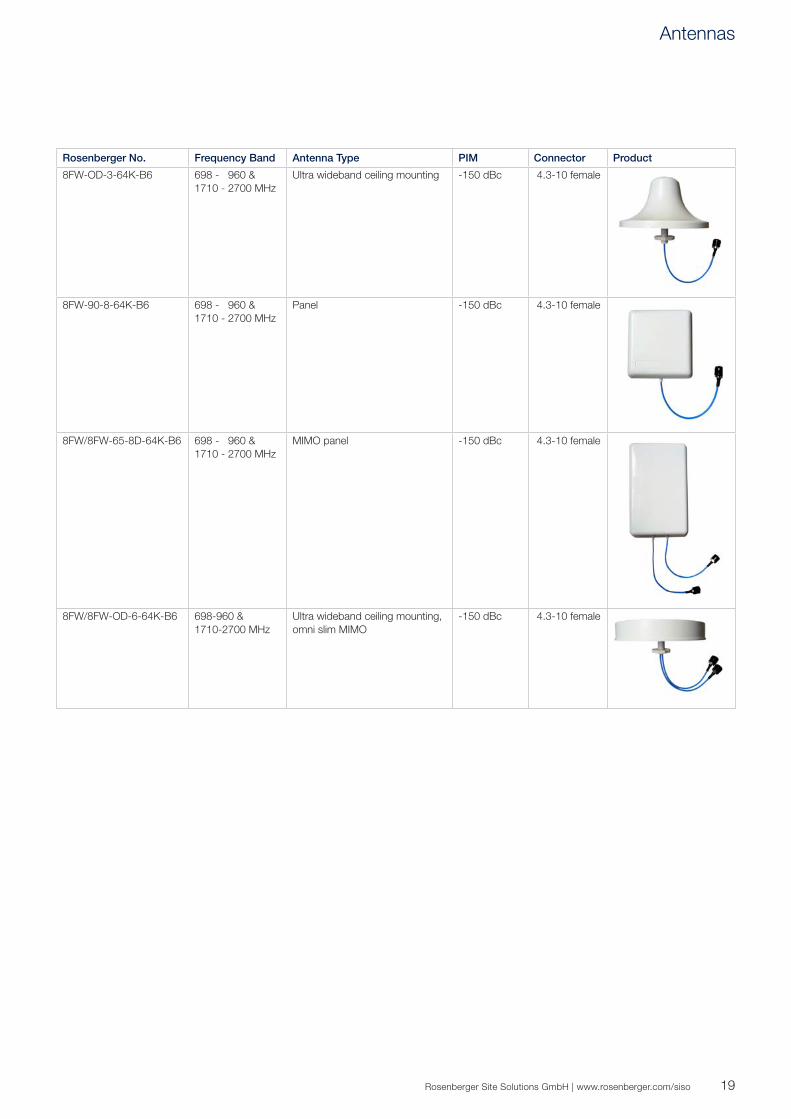
Rosenberger No. Frequency Band Antenna Type PIM Connector Product
8FW-OD-3-64K-B6 698 - 960 & 1710 - 2700 MHz
Ultra wideband ceiling mounting -150 dBc 4.3-10 female
8FW-90-8-64K-B6 698 - 960 & 1710 - 2700 MHz
Panel -150 dBc 4.3-10 female
8FW/8FW-65-8D-64K-B6 698 - 960 & 1710 - 2700 MHz
MIMO panel -150 dBc 4.3-10 female
8FW/8FW-OD-6-64K-B6 698-960 & 1710-2700 MHz
Ultra wideband ceiling mounting, omni slim MIMO
-150 dBc 4.3-10 female
Antennas

4.3-10 Connectors
As a global leader in RF technology, Rosenberger has been an active partner in the development of the 4.3-10 connector series for mobile communications applications.
The 4.3-10 connector series has been designed to meet rising electrical and mechanical performance require-ments – as well as provide for a low footprint due to ongoing space reductions of infrastructure equipment.
Very Low PIM – Independent of TorqueThe 4.3-10 connector series is characterized by optimal electrical performance and very low passive inter-modulation – independent of torque. Due to its dimensions, 4.3-10 connectors are the natural evolution of connector systems used today used in the mobile communications industry.
Electrical and mechanical planes have been separated, leading to significantly lower coupling torque. 4.3-10 connectors are available in three versions: Screw-on (HEX), hand-screw, and push-pull coupling mechanisms.
One Jack for All Plug TypesDue to its mechanical design, the universal 4.3-10 jack type can be mated to all plug types:
Screw Type (HEX) Screw type with recommended tightening
torque of 5 Nm Recommended for harsh environments
Hand Screw Type Hand screw (no torque) Special release to prevent the nut from
unintentionally becoming loose
Push-Pull Type Quick connection type No tools needed Self-locking
Universal Jack One jack for all 4.3-10 plug types
Hand Screw Push-Pull
Universal Jack
Screw (HEX)
20

21Rosenberger Site Solutions GmbH | www.rosenberger.com/siso
Connectors in Comparison – Technical DataConnector Type 4.3-10 7-16 (DIN) N Series
Minimum flange size 25.4 mm 32 mm 32 mm
Return loss ≥ 36 dB @ DC to 4 GHz≥ 32 dB @ 4 GHz to 6 GHz
≥ 36 dB @ DC to 4 GHz≥ 32 dB @ 4 GHz to 6 GHz
≥ 35 dB @ DC to 1 GHz≥ 30 dB @ 1 GHz to 2.7 GHz
RF leakage ≥ 120 dB @ DC to 3 GHz (screw, HEX)≥ 90 dB @ DC to 3 GHz (hand-screw)≥ 70 dB @ 3 to 6 GHz (push-pull)
≥ 110 dB @ DC to 1 GHz (tool types)
≥ 110 dB @ DC to 1 GHz (tool types)
Passive intermodulation ≥ 166 dBc @ 2 x 43 dBm ≥ 160 dBc @ 2 x 43 dBm ≥ 160 dBc @ 2 x 43 dBm
Degree of protection (water tightness) IP 68 (@ 25 m, 1 hour) IP 68 (@ 25 m, 1 hour) IP 68 (@ 25 m, 1 hour)
Mating cycles ≥ 100 ≥ 500 ≥ 500
Coupling mechanisms Screw (HEX), hand-screw, push-pull Screw (HEX) Screw (HEX)
Coupling torque (screw-on type) > 5 Nm > 25 Nm 0.7 – 1.1 Nm
Torque Wrench and SpannersRosenberger No. Description Torque Setting Opening
64W022-001 Torque wrench for 4.3-10 5 ± 0.3 Nm 22 mm
53W010-000 Torque wrench for N 1.1 Nm 18 mm
60W000-002 Torque wrench for 7-16 25 Nm 32 mm
99W057-000 Spanner, adjustable 0 - 35 mm
99W057-001 Spanner, adjustable 0 - 46 mm
4.3-10 Series
64W022-001 99W057-000
7-16 Series N Series
Features and Benefits Low, reliable, and constant PIM independent of torque Outstanding insertion/return loss Small foot print – 40% smaller than 7-16 connectors Low weight – 60% reduction compared to other RF interfaces High flexibility – 3 different plug types to mate with a universal jack
Connectors

4.3-10, 7-16, and N Connectors
22
4.3-10 ConnectorsRosenberger No.
Male Straight Male Right Angle Female Straight Feeder Cable Type
64S1C7-C01N1 64S2C7-C01N1 64K1C7-C01B1 1/4" Standard
64S1C7-C09N1 64S2C7-C09N1 64K1C7-C09B1 1/4" Super Flex
64S1C7-C02N1 64S2C7-C02N1 64K1C7-C02B1 3/8" Super Flex
64S1C7-C03N1 64S2C7-C03N1 64K1C7-C03B1 1/2" Standard
64S1C7-C08N1 64S2C7-C08N1 64K1C7-C08B1 1/2" Super Flex
64S1C7-CX5N1 64K1C7-CX5B1 7/8" Standard
64S1D7-C06N1 64K1D7-C06B1 1 1/4" Standard
64S1D7-C07N1 64K1D7-C07B1 1 5/8" Standard
7-16 ConnectorsRosenberger No.
Male Straight Male Right Angle Female Straight Feeder Cable Type
60S115-C01N1 60S215-C01N1 60K115-C01N1 1/4" Standard
60S115-C09N1 60S215-C09N1 60K115-C09N1 1/4" Super Flex
60S115-C02N1 60S215-C02N1 60K115-C02N1 3/8" Super Flex
60S1C7-C03N1 60S2C7-C03N1 60K1C7-C03N1 1/2" Standard
60S1C7-C08N1 60S2C7-C08N1 60K1C7-C08N1 1/2" Super Flex
60S1C7-CX5N1 60K1C7-CX5N1 7/8" Standard
60S1D7-C06N1 60K1D7-C06N1 1 1/4" Standard
60S1D7-C07N1 60K1D7-C07N1 1 5/8" Standard
N ConnectorsRosenberger No.
Male Straight Male Right Angle Female Straight Feeder Cable Type
53S115-C01N1 53S215-C01N1 53K115-C01N1 1/4" Standard
53S115-C09N1 53S215-C09N1 53K115-C09N1 1/4" Super Flex
53S1C7-C03N1 53S2C7-C03N1 53K1C7-C03N1 1/2" Standard
53S1C7-C08N1 53S2C7-C08N1 53K1C7-C08N1 1/2" Super Flex
53S1C7-CX5N1 53K1C7-CX5N1 7/8" Standard
53S1D7-C06N1 53K1D7-C06N1 1 1/4" Standard
53S1D7-C07N1 53K1D7-C07N1 1 5/8" Standard
Connectors
23Rosenberger Site Solutions GmbH | www.rosenberger.com/siso
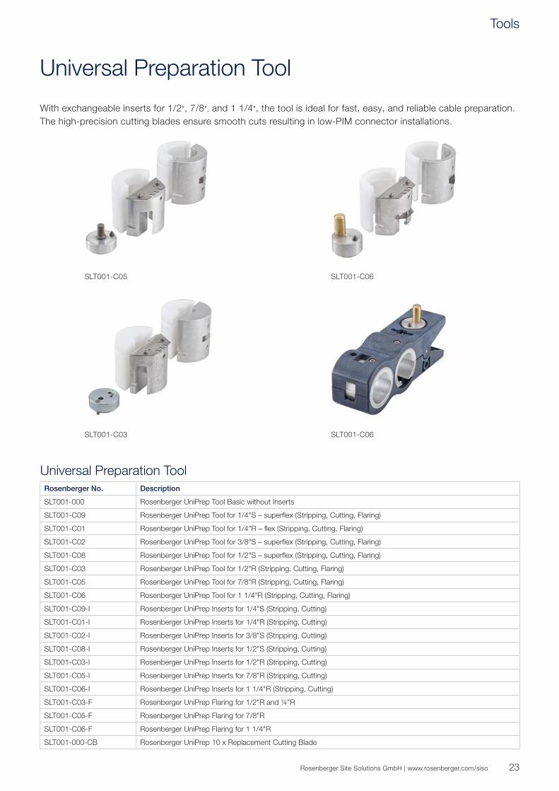
Universal Preparation Tool
With exchangeable inserts for 1/2", 7/8", and 1 1/4", the tool is ideal for fast, easy, and reliable cable preparation. The high-precision cutting blades ensure smooth cuts resulting in low-PIM connector installations.
SLT001-C06
SLT001-C06
SLT001-C05
SLT001-C03
Universal Preparation ToolRosenberger No. Description
SLT001-000 Rosenberger UniPrep Tool Basic without Inserts
SLT001-C09 Rosenberger UniPrep Tool for 1/4"S – superflex (Stripping, Cutting, Flaring)
SLT001-C01 Rosenberger UniPrep Tool for 1/4"R – flex (Stripping, Cutting, Flaring)
SLT001-C02 Rosenberger UniPrep Tool for 3/8"S – superflex (Stripping, Cutting, Flaring)
SLT001-C08 Rosenberger UniPrep Tool for 1/2"S – superflex (Stripping, Cutting, Flaring)
SLT001-C03 Rosenberger UniPrep Tool for 1/2"R (Stripping, Cutting, Flaring)
SLT001-C05 Rosenberger UniPrep Tool for 7/8"R (Stripping, Cutting, Flaring)
SLT001-C06 Rosenberger UniPrep Tool for 1 1/4"R (Stripping, Cutting, Flaring)
SLT001-C09-I Rosenberger UniPrep Inserts for 1/4"S (Stripping, Cutting)
SLT001-C01-I Rosenberger UniPrep Inserts for 1/4"R (Stripping, Cutting)
SLT001-C02-I Rosenberger UniPrep Inserts for 3/8"S (Stripping, Cutting)
SLT001-C08-I Rosenberger UniPrep Inserts for 1/2"S (Stripping, Cutting)
SLT001-C03-I Rosenberger UniPrep Inserts for 1/2"R (Stripping, Cutting)
SLT001-C05-I Rosenberger UniPrep Inserts for 7/8"R (Stripping, Cutting)
SLT001-C06-I Rosenberger UniPrep Inserts for 1 1/4"R (Stripping, Cutting)
SLT001-C03-F Rosenberger UniPrep Flaring for 1/2"R and ¼"R
SLT001-C05-F Rosenberger UniPrep Flaring for 7/8"R
SLT001-C06-F Rosenberger UniPrep Flaring for 1 1/4"R
SLT001-000-CB Rosenberger UniPrep 10 x Replacement Cutting Blade
Tools

24
Low-PIM, On-Site Connector Installation
To achieve the best PIM test results we recommend following the procedures below in addition to the recommendations outlined in the assembly instructions included with each individual connector.
It is very important to keep the prepped cable and connectors absolutely clean of dirt, metal particles, and scratches.
Prepare the cable according to assembly instructions (e.g. with tool SLT001-Cxx).
Use a plastic tool for removing the cut-off bond on the dielectric (e.g. SLT004-000).
Before finally attaching the connector to the cable, clean the contact areas of the cables with alcohol by using non-metallic cleaning brushes/tools (e.g., SLZ0009-000).
SLZ0009-000
On cables with tube inner conduc-tor, remove burrs and sharp edges on the inside of the conductor (e.g. flaring tool integrated in tool SLT001-Cxx).
Tools
25Rosenberger Site Solutions GmbH | www.rosenberger.com/siso
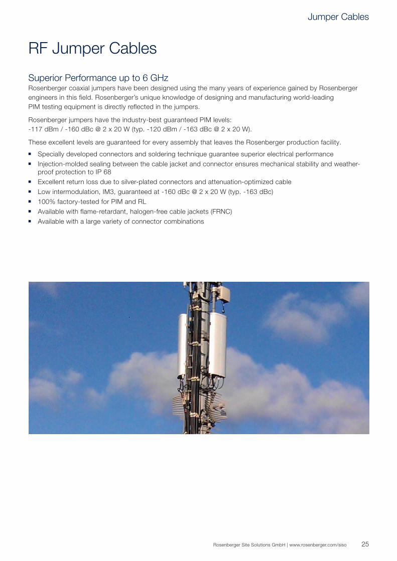
RF Jumper Cables
Superior Performance up to 6 GHzRosenberger coaxial jumpers have been designed using the many years of experience gained by Rosenberger engineers in this field. Rosenberger’s unique knowledge of designing and manufacturing world-leading PIM testing equipment is directly reflected in the jumpers.
Rosenberger jumpers have the industry-best guaranteed PIM levels: -117 dBm / -160 dBc @ 2 x 20 W (typ. -120 dBm / -163 dBc @ 2 x 20 W).
These excellent levels are guaranteed for every assembly that leaves the Rosenberger production facility.
Specially developed connectors and soldering technique guarantee superior electrical performance Injection-molded sealing between the cable jacket and connector ensures mechanical stability and weather-
proof protection to IP 68 Excellent return loss due to silver-plated connectors and attenuation-optimized cable Low intermodulation, IM3, guaranteed at -160 dBc @ 2 x 20 W (typ. -163 dBc) 100% factory-tested for PIM and RL Available with flame-retardant, halogen-free cable jackets (FRNC) Available with a large variety of connector combinations
Jumper Cables
26
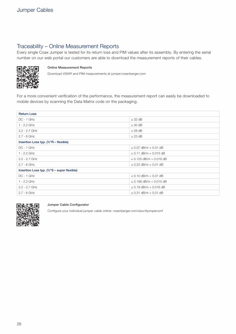
Online Measurement Reports
Download VSWR and PIM measurements at jumper.rosenberger.com
For a more convenient verification of the performance, the measurement report can easily be downloaded to mobile devices by scanning the Data Matrix code on the packaging.
Traceability – Online Measurement ReportsEvery single Coax Jumper is tested for its return loss and PIM values after its assembly. By entering the serial number on our web portal our customers are able to download the measurement reports of their cables.
Return Loss
DC - 1 GHz ≥ 32 dB
1 - 2.2 GHz ≥ 30 dB
2.2 - 2.7 GHz ≥ 28 dB
2.7 - 6 GHz ≥ 23 dB
Insertion Loss typ. (½"R – flexible)
DC - 1 GHz ≤ 0.07 dB/m + 0.01 dB
1 - 2.2 GHz ≤ 0.11 dB/m + 0.015 dB
2.2 - 2.7 GHz ≤ 0.125 dB/m + 0.016 dB
2.7 - 6 GHz ≤ 0.22 dB/m + 0.01 dB
Insertion Loss typ. (½"S – super flexible)
DC - 1 GHz ≤ 0.10 dB/m + 0.01 dB
1 - 2.2 GHz ≤ 0.168 dB/m + 0.015 dB
2.2 - 2.7 GHz ≤ 0.19 dB/m + 0.016 dB
2.7 - 6 GHz ≤ 0.31 dB/m + 0.01 dB
Jumper Cable Configurator
Configure your individual jumper cable online: rosenberger.com/siso/#jumperconf
Jumper Cables

27Rosenberger Site Solutions GmbH | www.rosenberger.com/siso
4.3-10 Coaxial Cable Connectors
Field Installable 4.3-10 Connector – Corrugated CablesRosenberger connectors have excellent mechanical and environmental properties that ensure long-term durability and performance in both indoor and outdoor installations.
All Rosenberger connectors are coated with white bronze plating. This coating has been selected specifically to provide protection against oxidation while delivering exceptional intermodulation performance and electrical conductivity.
4.3-10 Cable Connectors – Super Flexible Corrugated CablesConnector Type Rosenberger No.
1/4" super flexible corrugated 3/8" super flexible corrugated 1/2" super flexible corrugated
4.3-10 male straight; screw type 64S1C7-C09N1 64S1C7-C02N1 64S1C7-C08N1
4.3-10 male right angle; screw type 64S2C7-C09N1 64S2C7-C02N1 64S2C7-C08N1
4.3-10 female straight 64K1C7-C09B1 64K1C7-C02B1 64K1C7-C08B1
4.3-10 Cable Connectors – Flexible Corrugated CablesConnector Type Rosenberger No.
1/2" flexible corrugated 7/8" flexible corrugated 1 1/4" flexible corrugated 1 5/8" flexible corrugated
4.3-10 male straight; screw type 64S1C7-C03N1 64S1C7-CX5N1 64S1D7-C06N1 64S1D7-C07N1
4.3-10 male right angle; screw type 64S2C7-C03N1
4.3-10 female straight 64K1C7-C03B1 64K1C7-CX5B1 64K1D7-C06B1 64K1D7-C07B1
64S1C7-C08N1
Coax Cables
28
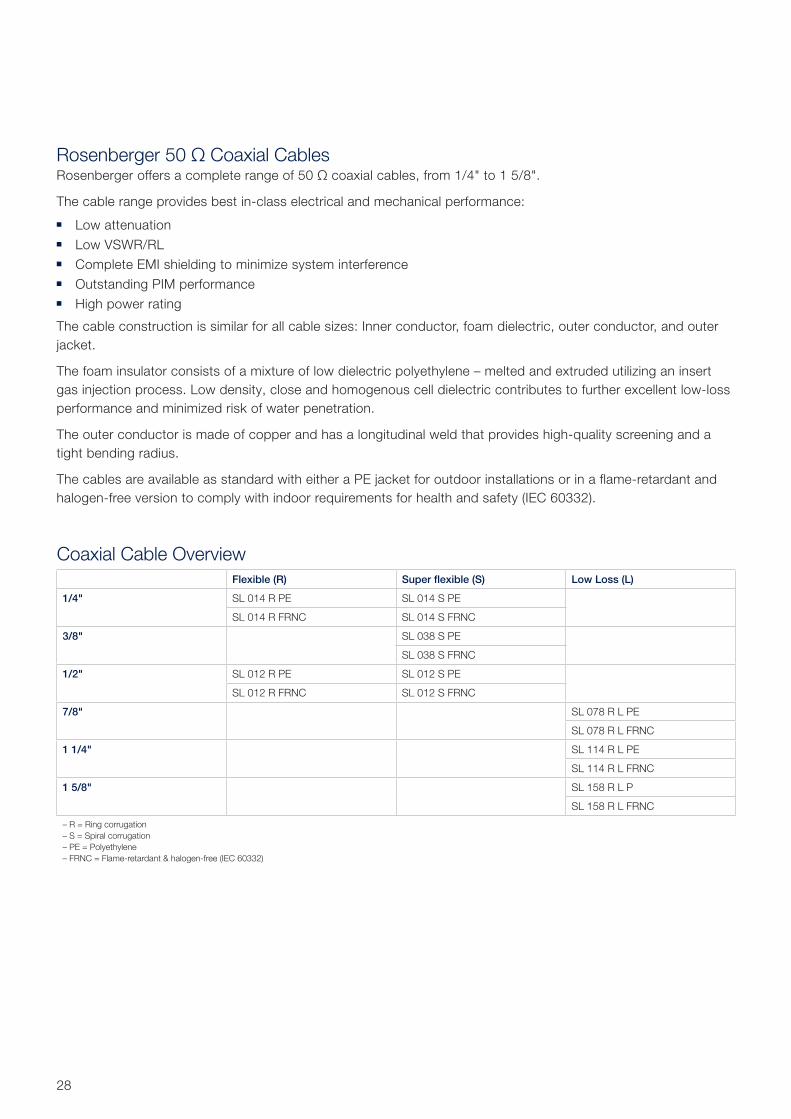
Rosenberger 50 Ω Coaxial CablesRosenberger offers a complete range of 50 Ω coaxial cables, from 1/4" to 1 5/8".
The cable range provides best in-class electrical and mechanical performance:
Low attenuation Low VSWR/RL Complete EMI shielding to minimize system interference Outstanding PIM performance High power rating
The cable construction is similar for all cable sizes: Inner conductor, foam dielectric, outer conductor, and outer jacket.
The foam insulator consists of a mixture of low dielectric polyethylene – melted and extruded utilizing an insert gas injection process. Low density, close and homogenous cell dielectric contributes to further excellent low-loss performance and minimized risk of water penetration.
The outer conductor is made of copper and has a longitudinal weld that provides high-quality screening and a tight bending radius.
The cables are available as standard with either a PE jacket for outdoor installations or in a flame-retardant and halogen-free version to comply with indoor requirements for health and safety (IEC 60332).
Coaxial Cable OverviewFlexible (R) Super flexible (S) Low Loss (L)
1/4" SL 014 R PE SL 014 S PE
SL 014 R FRNC SL 014 S FRNC
3/8" SL 038 S PE
SL 038 S FRNC
1/2" SL 012 R PE SL 012 S PE
SL 012 R FRNC SL 012 S FRNC
7/8" SL 078 R L PE
SL 078 R L FRNC
1 1/4" SL 114 R L PE
SL 114 R L FRNC
1 5/8" SL 158 R L P
SL 158 R L FRNC
– R = Ring corrugation– S = Spiral corrugation– PE = Polyethylene– FRNC = Flame-retardant & halogen-free (IEC 60332)
29Rosenberger Site Solutions GmbH | www.rosenberger.com/siso
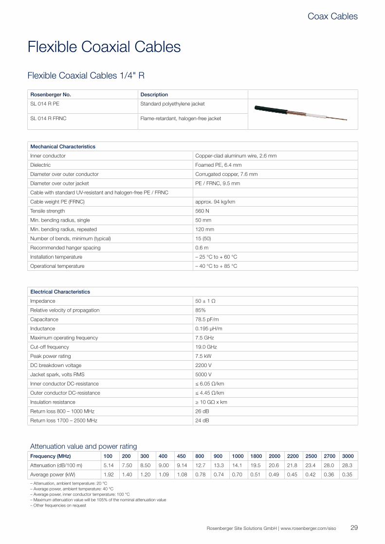
Flexible Coaxial Cables
Flexible Coaxial Cables 1/4" R
Rosenberger No. Description
SL 014 R PE Standard polyethylene jacket
SL 014 R FRNC Flame-retardant, halogen-free jacket
Mechanical Characteristics
Inner conductor Copper-clad aluminum wire, 2.6 mm
Dielectric Foamed PE, 6.4 mm
Diameter over outer conductor Corrugated copper, 7.6 mm
Diameter over outer jacket PE / FRNC, 9.5 mm
Cable with standard UV-resistant and halogen-free PE / FRNC
Cable weight PE (FRNC) approx. 94 kg/km
Tensile strength 560 N
Min. bending radius, single 50 mm
Min. bending radius, repeated 120 mm
Number of bends, minimum (typical) 15 (50)
Recommended hanger spacing 0.6 m
Installation temperature – 25 °C to + 60 °C
Operational temperature – 40 °C to + 85 °C
Electrical Characteristics
Impedance 50 ± 1 Ω
Relative velocity of propagation 85%
Capacitance 78.5 pF/m
Inductance 0.195 μH/m
Maximum operating frequency 7.5 GHz
Cut-off frequency 19.0 GHz
Peak power rating 7.5 kW
DC breakdown voltage 2200 V
Jacket spark, volts RMS 5000 V
Inner conductor DC-resistance ≤ 6.05 Ω/km
Outer conductor DC-resistance ≤ 4.45 Ω/km
Insulation resistance ≥ 10 GΩ x km
Return loss 800 – 1000 MHz 26 dB
Return loss 1700 – 2500 MHz 24 dB
Attenuation value and power ratingFrequency (MHz) 100 200 300 400 450 800 900 1000 1800 2000 2200 2500 2700 3000
Attenuation (dB/100 m) 5.14 7.50 8.50 9.00 9.14 12.7 13.3 14.1 19.5 20.6 21.8 23.4 28.0 28.3
Average power (kW) 1.92 1.40 1.20 1.09 1.08 0.78 0.74 0.70 0.51 0.49 0.45 0.42 0.36 0.35
– Attenuation, ambient temperature: 20 °C– Average power, ambient temperature: 40 °C– Average power, inner conductor temperature: 100 °C– Maximum attenuation value will be 105% of the nominal attenuation value– Other frequencies on request
Coax Cables

30
Flexible Corrugated Cables 1/2" R
Rosenberger No. Description
SL 012 R PE Standard polyethylene jacket
SL 012 R FRNC Flame-retardant, halogen-free jacket
Mechanical Characteristics
Inner conductor Copper-clad aluminum wire, 4.8 mm
Dielectric Foamed PE, 12.1 mm
Diameter over outer conductor Corrugated copper tube, 13.8 mm
Diameter over outer jacket PE / FRNC, 15.9 mm
Cable with standard UV-resistant and halogen-free PE / FRNC
Cable weight PE (FRNC) 210 kg/km (245 kg/km)
Tensile strength 1150 N
Min. bending radius, single 50 mm
Min. bending radius, repeated 125 mm
Number of bends, minimum (typical) 15 (50)
Recommended hanger spacing 0.8 m
Installation temperature – 25 °C to + 60 °C
Operational temperature – 40 °C to + 85 °C
Electrical Characteristics
Impedance 50 ± 1 Ω
Relative velocity of propagation 88%
Capacitance 76 pF/m
Inductance 0.190 μH/m
Maximum operating frequency 8.8 GHz
Cut-off frequency 10.0 GHz
Peak power rating 40 kW
DC breakdown voltage 6000 V
Jacket spark, volts RMS 8000 V
Inner conductor DC-resistance 1.5 Ω/km
Outer conductor DC-resistance 2.3 Ω/km
Insulation resistance ≥ 10 GΩ x km
Return loss 800 – 1000 MHz 26 dB
Return loss 1700 – 2500 MHz 24 dB
Attenuation value and power ratingFrequency (MHz) 100 200 300 400 450 800 900 1000 1800 2000 2200 2500 2700 3000
Attenuation (dB/100 m) 2.15 3.08 3.81 4.46 4.70 6.35 6.75 7.20 9.90 10.50 11.10 11.95 12.47 13.20
Average power (kW) 3.94 2.75 1.99 1.80 1.80 1.33 1.25 1.18 0.86 0.81 0.77 0.73 0.69 0.65
– Attenuation, ambient temperature: 20 °C– Average power, ambient temperature: 40 °C– Average power, inner conductor temperature: 100 °C– Maximum attenuation value will be 105% of the nominal attenuation value– Other frequencies on request

31Rosenberger Site Solutions GmbH | www.rosenberger.com/siso
Rosenberger Super Flexible Coaxial Cables
Rosenberger Super Flexible coaxial cables are designed for use in tight routing spaces. Typical applications include connections inside mobile base stations and jumpers for connecting the base stations, transmission lines, and antennas.
Super Flexible cables have superior electrical and mechanical performance, and are ideal for applications requiring the tightest bending radii, high flexibility, low attenuation, and high shielding.
Rosenberger Super Flexible coaxial cable assemblies achieve the highest standards in the industry including excellent inter modulation (IM3) and return loss performance.
The inner conductor consists of a copper-clad aluminum wire. The outer conductor is made of a welded copper tube with spiral corrugations and marked accordingly with the letter 'S'.
The Rosenberger Super Flexible coaxial cables are available with outer jackets made of either polyethylene or flame-retardant, halogen-free materials.
Coax Cables
32
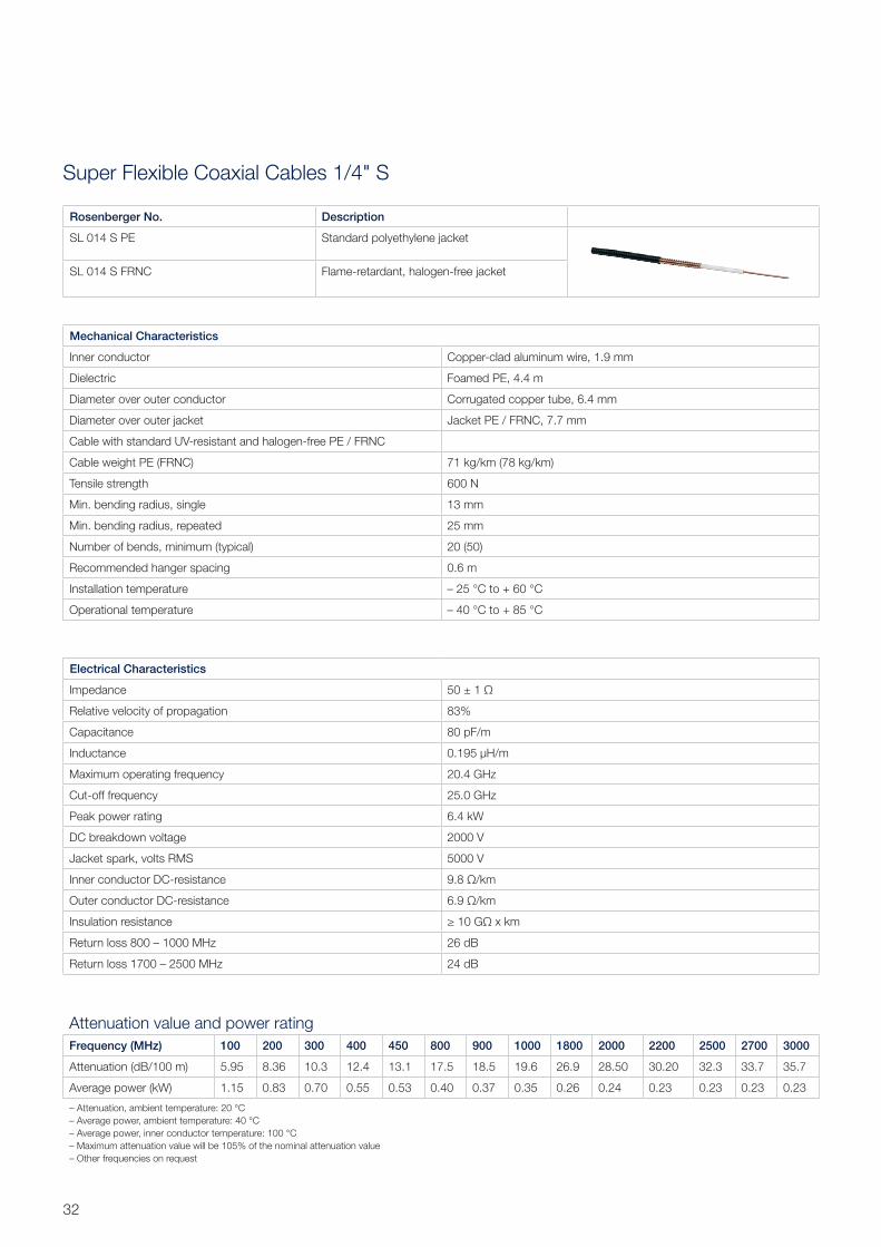
Super Flexible Coaxial Cables 1/4" S
Rosenberger No. Description
SL 014 S PE Standard polyethylene jacket
SL 014 S FRNC Flame-retardant, halogen-free jacket
Mechanical Characteristics
Inner conductor Copper-clad aluminum wire, 1.9 mm
Dielectric Foamed PE, 4.4 m
Diameter over outer conductor Corrugated copper tube, 6.4 mm
Diameter over outer jacket Jacket PE / FRNC, 7.7 mm
Cable with standard UV-resistant and halogen-free PE / FRNC
Cable weight PE (FRNC) 71 kg/km (78 kg/km)
Tensile strength 600 N
Min. bending radius, single 13 mm
Min. bending radius, repeated 25 mm
Number of bends, minimum (typical) 20 (50)
Recommended hanger spacing 0.6 m
Installation temperature – 25 °C to + 60 °C
Operational temperature – 40 °C to + 85 °C
Electrical Characteristics
Impedance 50 ± 1 Ω
Relative velocity of propagation 83%
Capacitance 80 pF/m
Inductance 0.195 μH/m
Maximum operating frequency 20.4 GHz
Cut-off frequency 25.0 GHz
Peak power rating 6.4 kW
DC breakdown voltage 2000 V
Jacket spark, volts RMS 5000 V
Inner conductor DC-resistance 9.8 Ω/km
Outer conductor DC-resistance 6.9 Ω/km
Insulation resistance ≥ 10 GΩ x km
Return loss 800 – 1000 MHz 26 dB
Return loss 1700 – 2500 MHz 24 dB
Attenuation value and power ratingFrequency (MHz) 100 200 300 400 450 800 900 1000 1800 2000 2200 2500 2700 3000
Attenuation (dB/100 m) 5.95 8.36 10.3 12.4 13.1 17.5 18.5 19.6 26.9 28.50 30.20 32.3 33.7 35.7
Average power (kW) 1.15 0.83 0.70 0.55 0.53 0.40 0.37 0.35 0.26 0.24 0.23 0.23 0.23 0.23
– Attenuation, ambient temperature: 20 °C– Average power, ambient temperature: 40 °C– Average power, inner conductor temperature: 100 °C– Maximum attenuation value will be 105% of the nominal attenuation value– Other frequencies on request
33Rosenberger Site Solutions GmbH | www.rosenberger.com/siso
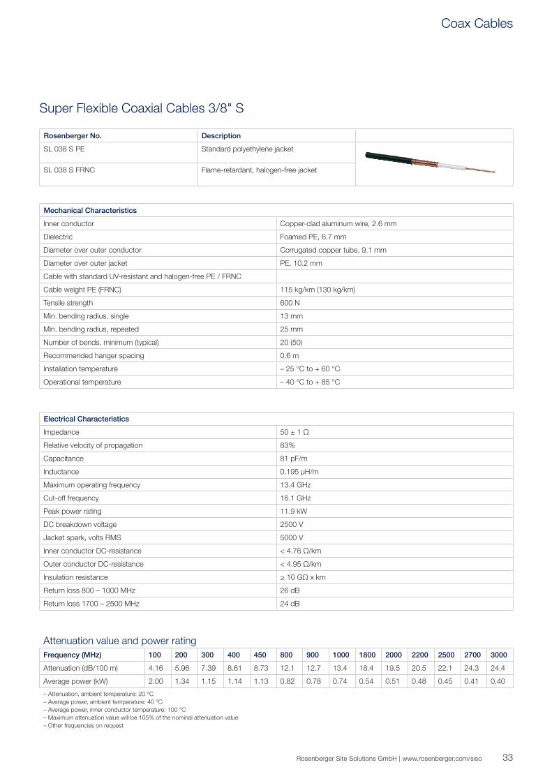
Super Flexible Coaxial Cables 3/8" S
Rosenberger No. Description
SL 038 S PE Standard polyethylene jacket
SL 038 S FRNC Flame-retardant, halogen-free jacket
Mechanical Characteristics
Inner conductor Copper-clad aluminum wire, 2.6 mm
Dielectric Foamed PE, 6.7 mm
Diameter over outer conductor Corrugated copper tube, 9.1 mm
Diameter over outer jacket PE, 10.2 mm
Cable with standard UV-resistant and halogen-free PE / FRNC
Cable weight PE (FRNC) 115 kg/km (130 kg/km)
Tensile strength 600 N
Min. bending radius, single 13 mm
Min. bending radius, repeated 25 mm
Number of bends, minimum (typical) 20 (50)
Recommended hanger spacing 0.6 m
Installation temperature – 25 °C to + 60 °C
Operational temperature – 40 °C to + 85 °C
Electrical Characteristics
Impedance 50 ± 1 Ω
Relative velocity of propagation 83%
Capacitance 81 pF/m
Inductance 0.195 μH/m
Maximum operating frequency 13.4 GHz
Cut-off frequency 16.1 GHz
Peak power rating 11.9 kW
DC breakdown voltage 2500 V
Jacket spark, volts RMS 5000 V
Inner conductor DC-resistance < 4.76 Ω/km
Outer conductor DC-resistance < 4.95 Ω/km
Insulation resistance ≥ 10 GΩ x km
Return loss 800 – 1000 MHz 26 dB
Return loss 1700 – 2500 MHz 24 dB
Attenuation value and power ratingFrequency (MHz) 100 200 300 400 450 800 900 1000 1800 2000 2200 2500 2700 3000
Attenuation (dB/100 m) 4.16 5.96 7.39 8.61 8.73 12.1 12.7 13.4 18.4 19.5 20.5 22.1 24.3 24.4
Average power (kW) 2.00 1.34 1.15 1.14 1.13 0.82 0.78 0.74 0.54 0.51 0.48 0.45 0.41 0.40
– Attenuation, ambient temperature: 20 °C– Average power, ambient temperature: 40 °C– Average power, inner conductor temperature: 100 °C– Maximum attenuation value will be 105% of the nominal attenuation value– Other frequencies on request
Coax Cables

34
Super Flexible Coaxial Cables 1/2" S
Rosenberger No. Description
SL 012 S PE Standard polyethylene jacket
SL 012 S FRNC Flame-retardant, halogen-free jacket
Mechanical Characteristics
Inner conductor Copper-clad aluminum wire, 3.6 mm
Dielectric Foamed PE, 9.0 mm
Diameter over outer conductor Corrugated copper tube, 12.2 mm
Diameter over outer jacket PE / FRNC, 13.4 mm
Cable with standard UV-resistant and halogen-free PE / FRNC
Cable weight PE (FRNC) 171 (184) kg/km
Tensile strength 750 N
Min. bending radius, single 25 mm
Min. bending radius, repeated 35 mm
Number of bends, minimum (typical) 20 (50)
Recommended hanger spacing 0.8 m
Installation temperature – 25 °C to + 60 °C
Operational temperature – 40 °C to + 85 °C
Electrical Characteristics
Impedance 50 ± 1 Ω
Relative velocity of propagation 83%
Capacitance 80 pF/m
Inductance 0.195 μH/m
Maximum operating frequency 10.2 GHz
Cut-off frequency 13.0 GHz
Peak power rating 16 kW
DC breakdown voltage 2500 V
Jacket spark, volts RMS 5000 V
Inner conductor DC-resistance 2.73 Ω/km
Outer conductor DC-resistance 3.68 Ω/km
Insulation resistance ≥ 10 GΩ x km
Return loss 800 – 1000 MHz 26 dB
Return loss 1700 – 2500 MHz 24 dB
Attenuation value and power ratingFrequency (MHz) 100 200 300 400 450 800 900 1000 1800 2000 2200 2500 2700 3000
Attenuation (dB/100 m) 3.31 4.84 6.07 7.11 7.59 10.40 11.20 11.80 16.00 17.20 18.20 19.50 20.50 21.90
Average power (kW) 3.16 2.17 1.71 1.47 1.38 1.01 0.95 0.89 0.63 0.60 0.56 0.52 0.50 0.48
– Attenuation, ambient temperature: 20 °C– Average power, ambient temperature: 40 °C– Average power, inner conductor temperature: 100 °C– Maximum attenuation value will be 105% of the nominal attenuation value– Other frequencies on request
35Rosenberger Site Solutions GmbH | www.rosenberger.com/siso
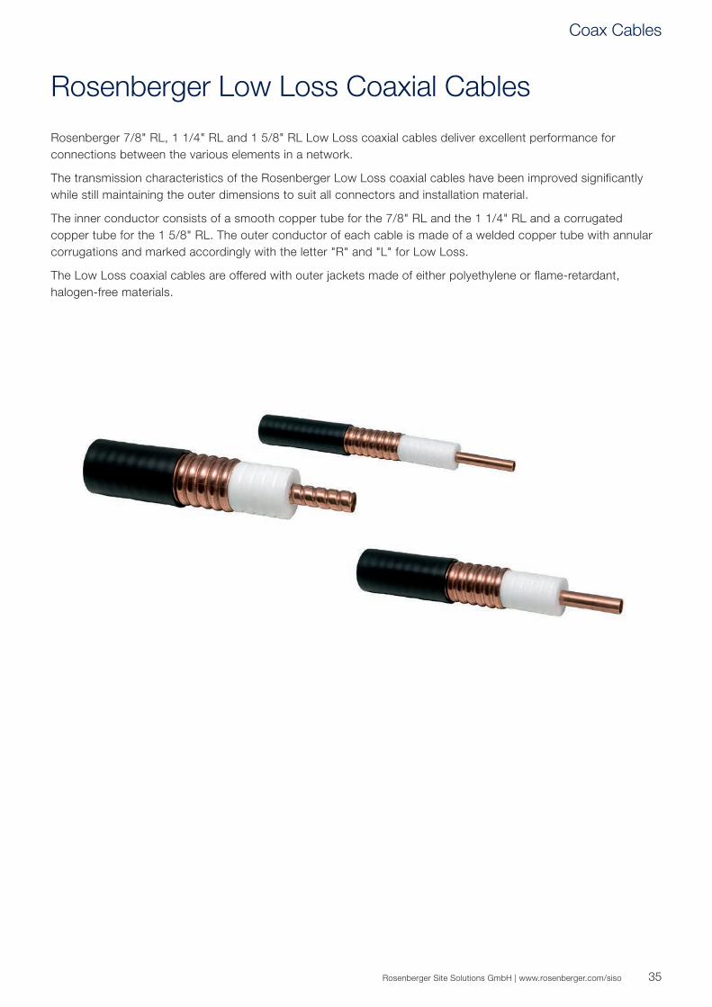
Rosenberger Low Loss Coaxial Cables
Rosenberger 7/8" RL, 1 1/4" RL and 1 5/8" RL Low Loss coaxial cables deliver excellent performance for connections between the various elements in a network.
The transmission characteristics of the Rosenberger Low Loss coaxial cables have been improved significantly while still maintaining the outer dimensions to suit all connectors and installation material.
The inner conductor consists of a smooth copper tube for the 7/8" RL and the 1 1/4" RL and a corrugated copper tube for the 1 5/8" RL. The outer conductor of each cable is made of a welded copper tube with annular corrugations and marked accordingly with the letter "R" and "L" for Low Loss.
The Low Loss coaxial cables are offered with outer jackets made of either polyethylene or flame-retardant, halogen-free materials.
Coax Cables
36
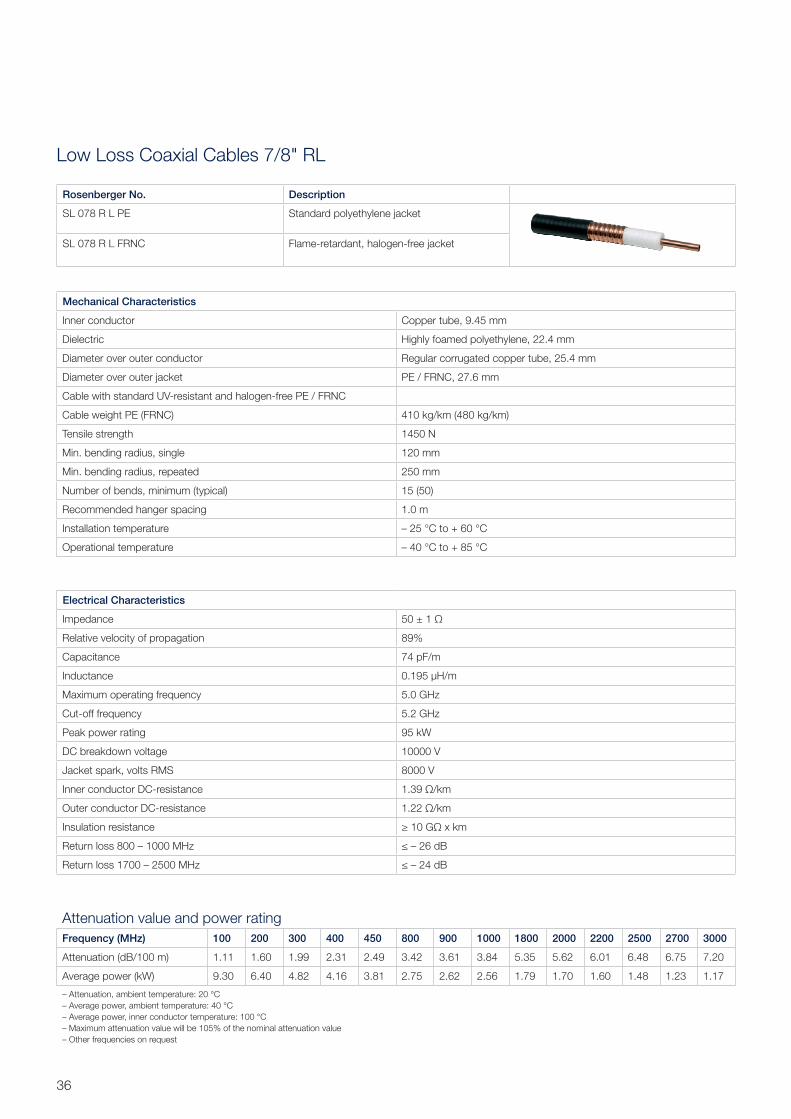
Low Loss Coaxial Cables 7/8" RL
Rosenberger No. Description
SL 078 R L PE Standard polyethylene jacket
SL 078 R L FRNC Flame-retardant, halogen-free jacket
Mechanical Characteristics
Inner conductor Copper tube, 9.45 mm
Dielectric Highly foamed polyethylene, 22.4 mm
Diameter over outer conductor Regular corrugated copper tube, 25.4 mm
Diameter over outer jacket PE / FRNC, 27.6 mm
Cable with standard UV-resistant and halogen-free PE / FRNC
Cable weight PE (FRNC) 410 kg/km (480 kg/km)
Tensile strength 1450 N
Min. bending radius, single 120 mm
Min. bending radius, repeated 250 mm
Number of bends, minimum (typical) 15 (50)
Recommended hanger spacing 1.0 m
Installation temperature – 25 °C to + 60 °C
Operational temperature – 40 °C to + 85 °C
Electrical Characteristics
Impedance 50 ± 1 Ω
Relative velocity of propagation 89%
Capacitance 74 pF/m
Inductance 0.195 μH/m
Maximum operating frequency 5.0 GHz
Cut-off frequency 5.2 GHz
Peak power rating 95 kW
DC breakdown voltage 10000 V
Jacket spark, volts RMS 8000 V
Inner conductor DC-resistance 1.39 Ω/km
Outer conductor DC-resistance 1.22 Ω/km
Insulation resistance ≥ 10 GΩ x km
Return loss 800 – 1000 MHz ≤ – 26 dB
Return loss 1700 – 2500 MHz ≤ – 24 dB
Attenuation value and power ratingFrequency (MHz) 100 200 300 400 450 800 900 1000 1800 2000 2200 2500 2700 3000
Attenuation (dB/100 m) 1.11 1.60 1.99 2.31 2.49 3.42 3.61 3.84 5.35 5.62 6.01 6.48 6.75 7.20
Average power (kW) 9.30 6.40 4.82 4.16 3.81 2.75 2.62 2.56 1.79 1.70 1.60 1.48 1.23 1.17
– Attenuation, ambient temperature: 20 °C– Average power, ambient temperature: 40 °C– Average power, inner conductor temperature: 100 °C– Maximum attenuation value will be 105% of the nominal attenuation value– Other frequencies on request
37Rosenberger Site Solutions GmbH | www.rosenberger.com/siso
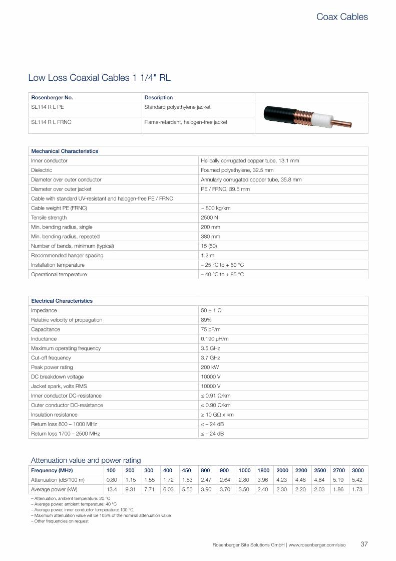
Low Loss Coaxial Cables 1 1/4" RL
Rosenberger No. Description
SL114 R L PE Standard polyethylene jacket
SL114 R L FRNC Flame-retardant, halogen-free jacket
Mechanical Characteristics
Inner conductor Helically corrugated copper tube, 13.1 mm
Dielectric Foamed polyethylene, 32.5 mm
Diameter over outer conductor Annularly corrugated copper tube, 35.8 mm
Diameter over outer jacket PE / FRNC, 39.5 mm
Cable with standard UV-resistant and halogen-free PE / FRNC
Cable weight PE (FRNC) ~ 800 kg/km
Tensile strength 2500 N
Min. bending radius, single 200 mm
Min. bending radius, repeated 380 mm
Number of bends, minimum (typical) 15 (50)
Recommended hanger spacing 1.2 m
Installation temperature – 25 °C to + 60 °C
Operational temperature – 40 °C to + 85 °C
Electrical Characteristics
Impedance 50 ± 1 Ω
Relative velocity of propagation 89%
Capacitance 75 pF/m
Inductance 0.190 μH/m
Maximum operating frequency 3.5 GHz
Cut-off frequency 3.7 GHz
Peak power rating 200 kW
DC breakdown voltage 10000 V
Jacket spark, volts RMS 10000 V
Inner conductor DC-resistance ≤ 0.91 Ω/km
Outer conductor DC-resistance ≤ 0.90 Ω/km
Insulation resistance ≥ 10 GΩ x km
Return loss 800 – 1000 MHz ≤ – 24 dB
Return loss 1700 – 2500 MHz ≤ – 24 dB
Attenuation value and power ratingFrequency (MHz) 100 200 300 400 450 800 900 1000 1800 2000 2200 2500 2700 3000
Attenuation (dB/100 m) 0.80 1.15 1.55 1.72 1.83 2.47 2.64 2.80 3.96 4.23 4.48 4.84 5.19 5.42
Average power (kW) 13.4 9.31 7.71 6.03 5.50 3.90 3.70 3.50 2.40 2.30 2.20 2.03 1.86 1.73
– Attenuation, ambient temperature: 20 °C– Average power, ambient temperature: 40 °C– Average power, inner conductor temperature: 100 °C– Maximum attenuation value will be 105% of the nominal attenuation value– Other frequencies on request
Coax Cables
38
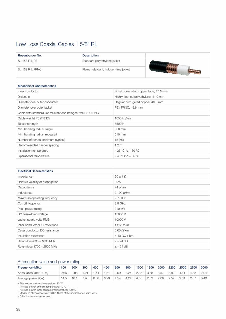
Low Loss Coaxial Cables 1 5/8" RL
Rosenberger No. Description
SL 158 R L PE Standard polyethylene jacket
SL 158 R L FRNC Flame-retardant, halogen-free jacket
Mechanical Characteristics
Inner conductor Spiral corrugated copper tube, 17.6 mm
Dielectric Highly foamed polyethylene, 41.0 mm
Diameter over outer conductor Regular corrugated copper, 46.5 mm
Diameter over outer jacket PE / FRNC, 49.8 mm
Cable with standard UV-resistant and halogen-free PE / FRNC
Cable weight PE (FRNC) 1055 kg/km
Tensile strength 3500 N
Min. bending radius, single 300 mm
Min. bending radius, repeated 510 mm
Number of bends, minimum (typical) 15 (50)
Recommended hanger spacing 1.2 m
Installation temperature – 25 °C to + 60 °C
Operational temperature – 40 °C to + 85 °C
Electrical Characteristics
Impedance 50 ± 1 Ω
Relative velocity of propagation 90%
Capacitance 74 pF/m
Inductance 0.190 μH/m
Maximum operating frequency 2.7 GHz
Cut-off frequency 2.9 GHz
Peak power rating 310 kW
DC breakdown voltage 15000 V
Jacket spark, volts RMS 10000 V
Inner conductor DC-resistance 1.25 Ω/km
Outer conductor DC-resistance 0.65 Ω/km
Insulation resistance ≥ 10 GΩ x km
Return loss 800 – 1000 MHz ≤ – 24 dB
Return loss 1700 – 2500 MHz ≤ – 24 dB
Attenuation value and power ratingFrequency (MHz) 100 200 300 400 450 800 900 1000 1800 2000 2200 2500 2700 3000
Attenuation (dB/100 m) 0.66 0.96 1.21 1.41 1.51 2.09 2.24 2.35 3.38 3.57 3.82 4.11 4.38 24.4
Average power (kW) 14.5 10.1 7.90 6.88 6.29 4.54 4.24 4.05 2.82 2.68 2.52 2.34 2.07 0.40
– Attenuation, ambient temperature: 20 °C– Average power, ambient temperature: 40 °C– Average power, inner conductor temperature: 100 °C– Maximum attenuation value will be 105% of the nominal attenuation value– Other frequencies on request

39Rosenberger Site Solutions GmbH | www.rosenberger.com/siso
4.3-10 Coax Jumper Assemblies
Rosenberger coaxial jumpers have been designed using the many years of experience gained by Rosenberger engineers in this field. Rosenberger’s unique knowledge of designing and manufacturing world-leading PIM testing equipment is directly reflected in the jumpers.
Technical DataRange Return Loss Insertion Loss typ.
(1/2"R – flexible)Insertion Loss typ. (1/2"S – super flexible)
DC - 1 GHz ≥ 32 dB ≤ 0.07 dB/m + 0.01 dB ≤ 0.10 dB/m + 0.01 dB
1 - 2.2 GHz ≥ 30 dB ≤ 0.11 dB/m + 0.015 dB ≤ 0.168 dB/m + 0.015 dB
2.2 - 2.7 GHz ≥ 28 dB ≤ 0.125 dB/m + 0.016 dB ≤ 0.19 dB/m + 0.016 dB
2.7 - 6 GHz ≥ 23 dB ≤ 0.22 dB/m + 0.01 dB ≤ 0.31 dB/m + 0.01 dB
RF Jumper Cables – Superior performance up to 6 GHzRosenberger Coax Jumpers have the industry-best PIM levels -117 dBm / 160 dBc @ 2 x 20 W (typ. -120 dBm / -163 dBc @ 2 x 20 W)
Traceability – Online Measurement ReportsEvery single Coax Jumper is tested for its return loss and PIM values after its assembly. By entering the serial number on our web portal our customers are able to download the measurement reports of their cables.
For a more convenient verification of the performance, the measurement report can easily be downloaded to mobile devices by scanning the Data Matrix code on the packaging.
Online Measurement Reports
Download VSWR and PIM measurements at jumper.rosenberger.com
Coax Cables
40
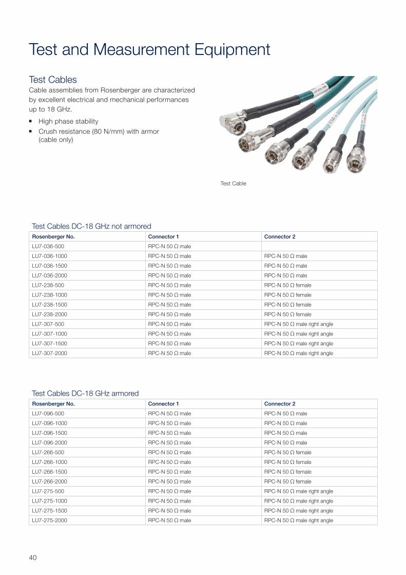
Test and Measurement Equipment
Test CablesCable assemblies from Rosen berger are characterized by excellent electrical and mechanical performances up to 18 GHz.
High phase stability Crush resistance (80 N/mm) with armor
(cable only)
Test Cable
Test Cables DC-18 GHz not armoredRosenberger No. Connector 1 Connector 2
LU7-036-500 RPC-N 50 Ω male
LU7-036-1000 RPC-N 50 Ω male RPC-N 50 Ω male
LU7-036-1500 RPC-N 50 Ω male RPC-N 50 Ω male
LU7-036-2000 RPC-N 50 Ω male RPC-N 50 Ω male
LU7-238-500 RPC-N 50 Ω male RPC-N 50 Ω female
LU7-238-1000 RPC-N 50 Ω male RPC-N 50 Ω female
LU7-238-1500 RPC-N 50 Ω male RPC-N 50 Ω female
LU7-238-2000 RPC-N 50 Ω male RPC-N 50 Ω female
LU7-307-500 RPC-N 50 Ω male RPC-N 50 Ω male right angle
LU7-307-1000 RPC-N 50 Ω male RPC-N 50 Ω male right angle
LU7-307-1500 RPC-N 50 Ω male RPC-N 50 Ω male right angle
LU7-307-2000 RPC-N 50 Ω male RPC-N 50 Ω male right angle
Test Cables DC-18 GHz armoredRosenberger No. Connector 1 Connector 2
LU7-096-500 RPC-N 50 Ω male RPC-N 50 Ω male
LU7-096-1000 RPC-N 50 Ω male RPC-N 50 Ω male
LU7-096-1500 RPC-N 50 Ω male RPC-N 50 Ω male
LU7-096-2000 RPC-N 50 Ω male RPC-N 50 Ω male
LU7-266-500 RPC-N 50 Ω male RPC-N 50 Ω female
LU7-266-1000 RPC-N 50 Ω male RPC-N 50 Ω female
LU7-266-1500 RPC-N 50 Ω male RPC-N 50 Ω female
LU7-266-2000 RPC-N 50 Ω male RPC-N 50 Ω female
LU7-275-500 RPC-N 50 Ω male RPC-N 50 Ω male right angle
LU7-275-1000 RPC-N 50 Ω male RPC-N 50 Ω male right angle
LU7-275-1500 RPC-N 50 Ω male RPC-N 50 Ω male right angle
LU7-275-2000 RPC-N 50 Ω male RPC-N 50 Ω male right angle
41Rosenberger Site Solutions GmbH | www.rosenberger.com/siso
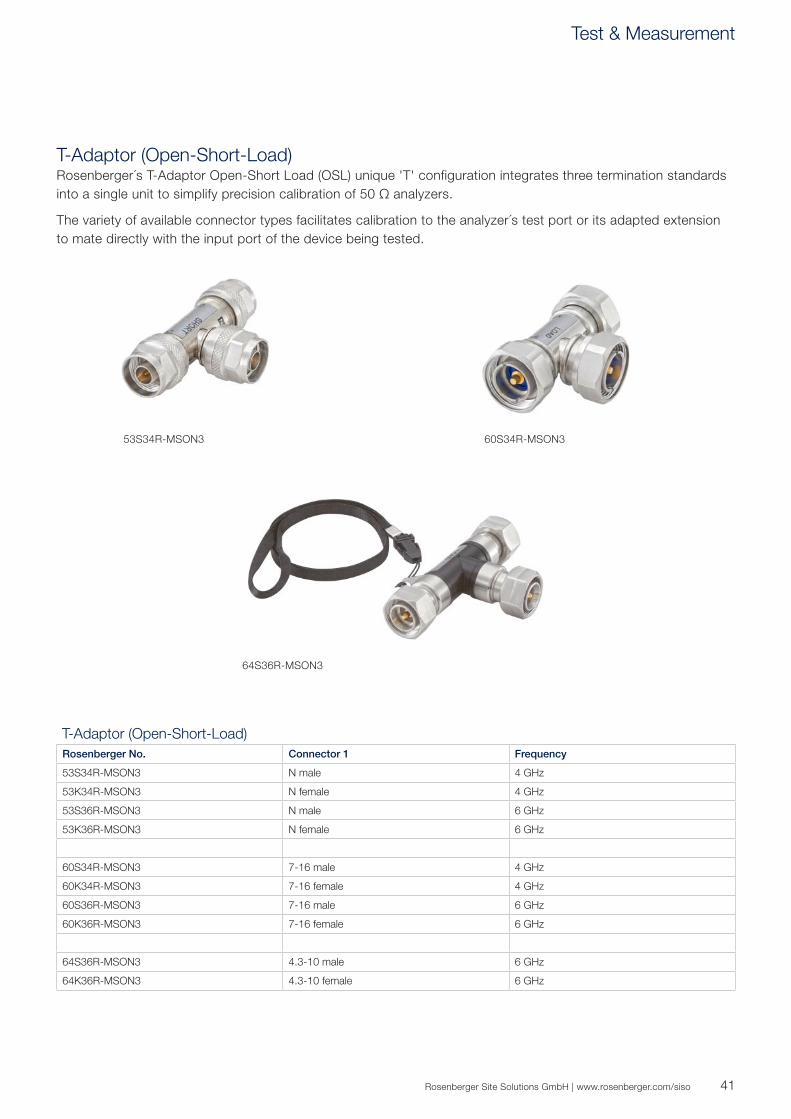
T-Adaptor (Open-Short-Load)Rosenberger´s T-Adaptor Open-Short Load (OSL) unique 'T' configuration integrates three termination standards into a single unit to simplify precision calibration of 50 Ω analyzers.
The variety of available connector types facilitates calibration to the analyzer´s test port or its adapted extension to mate directly with the input port of the device being tested.
53S34R-MSON3
64S36R-MSON3
60S34R-MSON3
T-Adaptor (Open-Short-Load)Rosenberger No. Connector 1 Frequency
53S34R-MSON3 N male 4 GHz
53K34R-MSON3 N female 4 GHz
53S36R-MSON3 N male 6 GHz
53K36R-MSON3 N female 6 GHz
60S34R-MSON3 7-16 male 4 GHz
60K34R-MSON3 7-16 female 4 GHz
60S36R-MSON3 7-16 male 6 GHz
60K36R-MSON3 7-16 female 6 GHz
64S36R-MSON3 4.3-10 male 6 GHz
64K36R-MSON3 4.3-10 female 6 GHz
Test & Measurement

42
LoadsFor testing and troubleshooting, these high-quality, precision loads are typically used to terminate system components at the characteristics impedance.
LoadsRosenberger No. Interface Frequency
05S150-010S3 N male 18 GHz, 0.5 W
05K150-010S3 N female 18 GHz, 0.5 W
60S17R-001N1 7-16 male 8 GHz, 1 W
60K17R-001N1 7-16 female 8 GHz, 1 W
64S17R-001S3 4.3-10 male 6 GHz, 1 W
64K17R-001S3 4.3.10-female 6 GHz, 1 W
05S150-010S3
64S17R-001S3
60S17R-001N1
43Rosenberger Site Solutions GmbH | www.rosenberger.com/siso
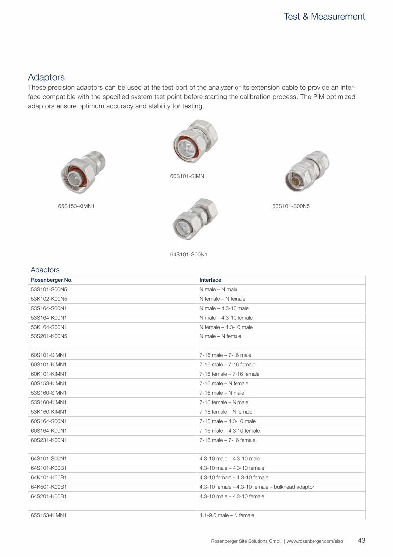
AdaptorsThese precision adaptors can be used at the test port of the analyzer or its extension cable to provide an inter-face compatible with the specified system test point before starting the calibration process. The PIM optimized adaptors ensure optimum accuracy and stability for testing.
AdaptorsRosenberger No. Interface
53S101-S00N5 N male – N male
53K102-K00N5 N female – N female
53S164-S00N1 N male – 4.3-10 male
53S164-K00N1 N male – 4.3-10 female
53K164-S00N1 N female – 4.3-10 male
53S201-K00N5 N male – N female
60S101-SIMN1 7-16 male – 7-16 male
60S101-KIMN1 7-16 male – 7-16 female
60K101-KIMN1 7-16 female – 7-16 female
60S153-KIMN1 7-16 male – N female
53S160-SIMN1 7-16 male – N male
53S160-KIMN1 7-16 female – N male
53K160-KIMN1 7-16 female – N female
60S164-S00N1 7-16 male – 4.3-10 male
60S164-K00N1 7-16 male – 4.3-10 female
60S231-K00N1 7-16 male – 7-16 female
64S101-S00N1 4.3-10 male – 4.3-10 male
64S101-K00B1 4.3-10 male – 4.3-10 female
64K101-K00B1 4.3-10 female – 4.3-10 female
64K501-K00B1 4.3-10 female – 4.3-10 female – bulkhead adaptor
64S201-K00B1 4.3-10 male – 4.3-10 female
65S153-KIMN1 4.1-9.5 male – N female
60S101-SIMN1
64S101-S00N1
65S153-KIMN1 53S101-S00N5
Test & Measurement

44
PIM Measurement
Excellent PIM performance is vital in today's mobile communications network. Rosenberger offers a complete range of PIM loads, measurement assemblies, and adaptors that meet our customers' expectations in terms of outstanding PIM performance.
Rosenberger No. Interface Frequency Product
60Z150-012 4.3-10 / 7-16 700 MHz to 3.6 GHz
60Z150-020 7-16 male – 7-16 female DC to 2.7 GHz
IM-Load-Site 4.3-10 4.3-10 male – 4.3-10 female DC to 2.7 GHz
Rosenberger No. Description Product
IM-Cable-716m-4310m-xxx 7-16 male – 4.3-10 female
IM-Cable-716m-716m-xxx 7-16 male – 7-16 male
IM-Cable-4310m-4310m-xxx 4.3-10 male – 4.3-10 male
xxx = cable length in mm
PIM Load and Test KitFor testing and troubleshooting, these high-quality precision loads are typically used to terminate system components at the characteristic impedance.
Measurement AssembliesThe PIM optimized measurement assemblies ensure optimum accuracy and stability for testing.

45Rosenberger Site Solutions GmbH | www.rosenberger.com/siso
Rosenberger No. Description Product
60S164-K00N1 7-16 male – 4.3-10 male
60S164-S00N1 7-16 male – 4.3-10 female
Rosenberger No. Description Product
SLTK003-000 7-16 contains a high-power, low-PIM load, different adaptors, highly flexible test cable 7-16 male to 7-16 male, torque wrench
SLTK003-001 4.3-10contains a high-power, low-PIM load, different adaptors, highly flexible test cable 4.3-10 male to 4.3-10 male, torque wrench
AdaptorsRosenberger precision adaptors can be used at the test port of the analyzer or its extension cable to provide an interface compatible the specified system test point. The PIM optimized adaptors ensure optimum accuracy and stability for testing.
PIM Test KitsCarry out high-precision and quality test and measurements with the Rosenberger test kits including test cables, adaptors, load, and torque wrench.
Test & Measurement

46
PIM Site Analyzer
Stressed PIM Tests without any Calibration on SiteThe Rosenberger portable and multifunctional broadband PIM Site Analyzer provides the best alternative of performing the most precise and efficient PIM tests on site.
The PIM Site Analyzer consists of a single Master Unit with band-specific, interchangeable filter units, since the form factor of the filter units is the same. Take out one filter unit, e.g., 900 MHz, and replace with another filter unit, e.g., 1800 MHz, without any calibration of the filter unit, potential adaptors, test cable, or operational mode(s). Future-proof Plug and Play concept covering 700 to 2700 MHz.
Benefits Broadband Base Unit 700 - 2700 MHz with field interchangeable, band-specific filter units Stressed PIM tests – continuous wave (CW) signal simulates real operating conditions of the base station
(in conformity with IEC 62037-1) Outstanding PIM performance <-125 dBm (<-130 dBm typ.) No on-site calibration Accuracy of < 0.3 m for PIM Distance to Fault (DTF) measurement Future-proof for upcoming bands Hardware ready for later CPRI SW upgrade
Additional Features In-built WiFi for remote control via optional 10" Android tablet Operation via batteries or external power supply VSWR/return loss measurements Antenna isolation measurement Integrated spectrum analyzer 12" touchscreen Intuitive software operation
Filter Units 700, 800, 900, 1800, 2100, 2600 MHz
(other frequency bands on request)

47Rosenberger Site Solutions GmbH | www.rosenberger.com/siso
PIM Site Analyzer
Base unit includes:
1 filter unit 2 batteries External power unit Charging cable
PIM Site Analyzer Broadband Base UnitRosenberger No. Frequency
Range RXFrequency Range TX
Power Output RX Noise Floor
IM-B-BU-0727 698 - 2700 MHz see filter units 26 / 49 dBm < -135 dBm
Detailed specifications on request
PIM Site Analyzer Filter Units for 7-16Rosenberger No. Frequency Band E-UTRA
BandFrequency Range RX Frequency Range TX Power Output Residual IM
@ 2x43 dBm Reflected IM
IM-B-FI-700/B12-14 LTE 700 LU 12, 13, 14, 17 698 - 716 MHz 776 - 798 MHz
728 - 760 MHz +23 ... +46 dBm < -168 dBc
IM-B-FI-800/B20 DigDiv 20 832 - 862 MHz 792 - 822 MHz +23 ... +46 dBm < -168 dBc
IM-B-FI-850/B5 AMPS 800 5 824 - 849 MHz 869 - 894 MHz +23 ... +46 dBm < -168 dBc
IM-B-FI-900/B8 EGSM 900 8 880 - 915 MHz 925 - 960 MHz +23 ... +46 dBm < -168 dBc
IM-B-FI-1800/B3 DCS 1800 3 1710 - 1785 MHz 1805 - 1880 MHz +23 ... +46 dBm < -168 dBc
IM-B-FI-1900/B2+4 PCS 1900 / AWS 2, 4 1710 - 1910 MHz 1930 - 2155 MHz +23 ... +46 dBm < -168 dBc
IM-B-FI-700/B28 APT 700 28 703 - 748 MHz 758 - 803 MHz +23 ... +46 dBm < -168 dBc
IM-B-FI-1400/B11+21 LTE 1400 11, 21 1427.9 - 1462.9 MHz 1475.9 - 1510.9 MHz +23 ... +46 dBm < -168 dBc
IM-B-FI-2100/B1 UMTS 2100 1 1920 - 2060 MHz 2110 - 2170 MHz +23 ... +46 dBm < -168 dBc
IM-B-FI-2600/B7 UMTS II / LTE 2600 7 2545 - 2580 MHz 2620 - 2695 MHz +23 ... +46 dBm < -168 dBc
Detailed specifications on request
PIM Site Analyzer Filter Units for 4.3-10Rosenberger No. Frequency Band E-UTRA
BandFrequency Range RX Frequency Range TX Power Output Residual IM
@ 2x43 dBm Reflected IM
IM-B-FI-700/B12-14-G LTE 700 LU 12, 13, 14, 17 698 - 716 MHz 776 - 798 MHz
728 - 760 MHz +23 ... +46 dBm < -168 dBc
IM-B-FI-800/B20-G DigDiv 20 832 - 862 MHz 792 - 822 MHz +23 ... +46 dBm < -168 dBc
IM-B-FI-850/B5-G AMPS 800 5 824 - 849 MHz 869 - 894 MHz +23 ... +46 dBm < -168 dBc
IM-B-FI-900/B8-G EGSM 900 8 880 - 915 MHz 925 - 960 MHz +23 ... +46 dBm < -168 dBc
IM-B-FI-1800/B3-G DCS 1800 3 1710 - 1785 MHz 1805 - 1880 MHz +23 ... +46 dBm < -168 dBc
IM-B-FI-1900/B2+4-G PCS 1900 / AWS 2, 4 1710 - 1910 MHz 1930 - 2155 MHz +23 ... +46 dBm < -168 dBc
IM-B-FI-700/B28-G APT 700 28 703 - 748 MHz 758 - 803 MHz +23 ... +46 dBm < -168 dBc
IM-B-FI-1400/B11+21-G LTE 1400 11, 21 1427.9 - 1462.9 MHz 1475.9 - 1510.9 MHz +23 ... +46 dBm < -168 dBc
IM-B-FI-2100/B1-G UMTS 2100 1 1920 - 2060 MHz 2110 - 2170 MHz +23 ... +46 dBm < -168 dBc
IM-B-FI-2600/B7-G UMTS II / LTE 2600 7 2545 - 2580 MHz 2620 - 2695 MHz +23 ... +46 dBm < -168 dBc
Detailed specifications on request
Multi-functional PIM Site Analyzer
48
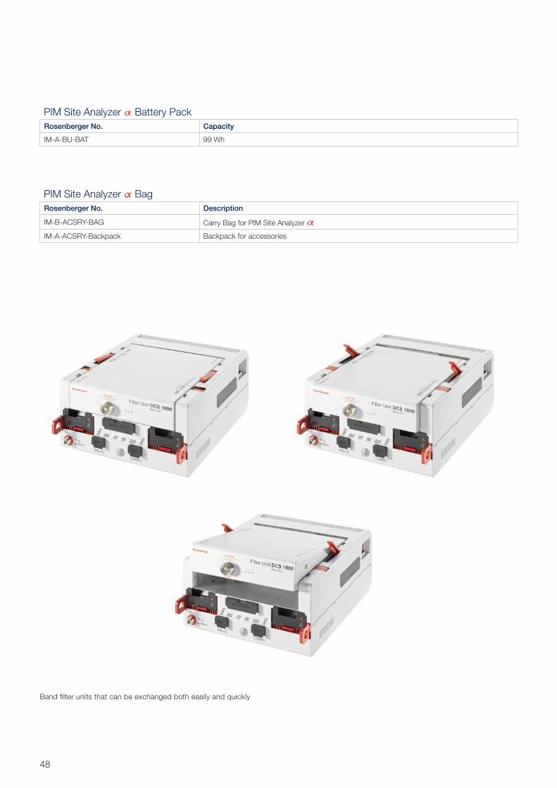
PIM Site Analyzer Battery PackRosenberger No. Capacity
IM-A-BU-BAT 99 Wh
PIM Site Analyzer BagRosenberger No. Description
IM-B-ACSRY-BAG Carry Bag for PIM Site Analyzer
IM-A-ACSRY-Backpack Backpack for accessories
Band filter units that can be exchanged both easily and quickly
49Rosenberger Site Solutions GmbH | www.rosenberger.com/siso
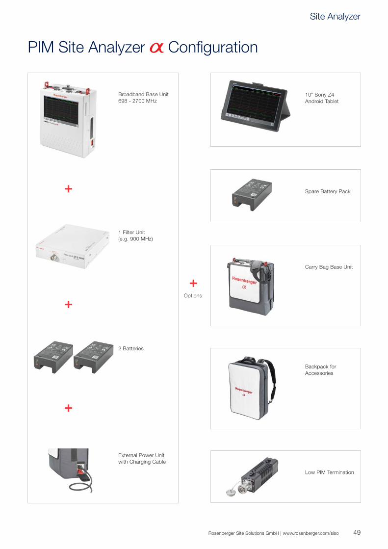
+Options
Spare Battery Pack
Carry Bag Base Unit
Backpack for Accessories
Low PIM Termination
10" Sony Z4 Android Tablet
+
+
2 Batteries
External Power Unit with Charging Cable
1 Filter Unit (e.g. 900 MHz)
Broadband Base Unit 698 - 2700 MHz
+
PIM Site Analyzer Configuration
Site Analyzer

50
Rosenberger No.05K150-010S3 4205S150-010S3 428FW/8FW-65-8D-64K-B6 198FW/8FW-OD-6-64K-B6 198FW-90-8-64K-B6 198FW-OD-3-64K-B6 1953K1C7-C03N1 2253K1C7-C08N1 2253K1C7-CX5N1 2253K1D7-C06N1 2253K1D7-C07N1 2253K34R-MSON3 4153K36R-MSON3 4153K102-K00N5 4353K115-C01N1 2253K115-C09N1 2253K160-KIMN1 4353K164-S00N1 4353S1C7-C03N1 2253S1C7-C08N1 2253S1C7-CX5N1 2253S1D7-C06N1 2253S1D7-C07N1 2253S2C7-C03N1 2253S2C7-C08N1 2253S34R-MSON3 4153S36R-MSON3 4153S101-S00N5 4353S115-C01N1 2253S115-C09N1 2253S160-KIMN1 4353S160-SIMN1 4353S164-K00N1 4353S164-S00N1 4353S201-K00N5 4353S215-C01N1 2253S215-C09N1 2253W010-000 2160K1C7-C03N1 2260K1C7-C08N1 2260K1C7-CX5N1 2260K1D7-C06N1 2260K1D7-C07N1 2260K17R-001N1 4260K34R-MSON3 4160K36R-MSON3 4160K101-KIMN1 4360K115-C01N1 2260K115-C02N1 2260K115-C09N1 2260S1C7-C03N1 2260S1C7-C08N1 2260S1C7-CX5N1 2260S1D7-C06N1 2260S1D7-C07N1 2260S2C7-C03N1 2260S2C7-C08N1 2260S17R-001N1 4260S34R-MSON3 4160S36R-MSON3 4160S101-KIMN1 4360S101-SIMN1 4360S115-C01N1 2260S115-C02N1 2260S115-C09N1 2260S153-KIMN1 4360S164-K00N1 43, 4560S164-S00N1 43, 4560S215-C01N1 2260S215-C02N1 2260S215-C09N1 2260S231-K00N1 43
60W000-002 2160Z150-012 4460Z150-020 4464K1C7-C01B1 2264K1C7-C02B1 22, 2764K1C7-C03B1 22, 2764K1C7-C08B1 22, 2764K1C7-C09B1 22, 2764K1C7-CX5B1 22, 2764K1D7-C06B1 22, 2764K1D7-C07B1 22, 2764K17R-001S3 4264K36R-MSON3 4164K101-K00B1 4364K501-K00B1 4364S1C7-C01N1 2264S1C7-C02N1 22, 2764S1C7-C03N1 22, 2764S1C7-C08N1 22, 2764S1C7-C09N1 22, 2764S1C7-CX5N1 22, 2764S1D7-C06N1 22, 2764S1D7-C07N1 22, 2764S2C7-C01N1 2264S2C7-C02N1 22, 2764S2C7-C03N1 22, 2764S2C7-C08N1 22, 2764S2C7-C09N1 22, 2764S17R-001S3 4264S36R-MSON3 4164S101-K00B1 4364S101-S00N1 4364S201-K00B1 4364W022-001 2165S153-KIMN1 4399W057-000 2199W057-001 21A-xx-50-64-T3 16A-xx-50-D-T1 16A-xx-50-N-T1 16A-xx-100-64-T3 16A-xx-100-D-T1 16A-xx-100-N-T1 16CB-2-DW-DF-02H-T3 14CB-2-FM-DF-01 14CB-2-LH-DF-01 14CB-2-LH-NF-01 14CB-3-DWE-DF-01 14CB-3-GDU-DF-04 14CB-4-GDWE-64F-01 14CB-4-GDWE-DF-08G 14CB-4-LCAP-64F-02 14CB-13-POI-64F-01 17DC-5-7F-NF-01 11DC-5-8F-DF-01 11DC-6-7F-DF-01 11DC-6-7F-NF-01 11DC-6-8F-64F-T 11DC-8-7F-DF-01 11DC-8-7F-NF-01 11DC-8-8F-64F-T 11DC-10-7F-DF-01 11DC-10-7F-NF-01 11DC-10-8F-64F-T 11DC-12-8F-64F-T 11DC-13-7F-DF-01 11DC-13-7F-NF-01 11DC-15-7F-DF-01 11DC-15-7F-NF-01 11DC-15-8F-64F-T 11DC-20-7F-DF-01 11DC-20-7F-NF-01 11

Rosenberger Site Solutions GmbH | www.rosenberger.com/siso 51
Status June 2017 – Technical modifications and errors excepted. Similar images.
DC-20-8F-64F-T 11DC-30-7F-DF-01 11DC-30-7F-NF -01 11DC-30-8F-64F-T 11HM-3-7F-DF-02 13HM-3-7F-NF-01 13HM-3-8F-64F-T 13HM-6-8F-64F-T 13HM-6-8F-DF-01 13HM-6-8F-NF-01 13IM-A-ACSRY-Backpack 48IM-A-BU-BAT 48IM-B-ACSRY-BAG 48IM-B-BU-0727 47IM-B-FI-700/B12-14 47IM-B-FI-700/B12-14-G 47IM-B-FI-700/B28 47IM-B-FI-700/B28-G 47IM-B-FI-800/B20 47IM-B-FI-800/B20-G 47IM-B-FI-850/B5 47IM-B-FI-850/B5-G 47IM-B-FI-900/B8 47IM-B-FI-900/B8-G 47IM-B-FI-1400/B11+21 47IM-B-FI-1400/B11+21-G 47IM-B-FI-1800/B3 47IM-B-FI-1800/B3-G 47IM-B-FI-1900/B2+4 47IM-B-FI-1900/B2+4-G 47IM-B-FI-2100/B1 47IM-B-FI-2100/B1-G 47IM-B-FI-2600/B7 47IM-B-FI-2600/B7-G 47IM-Cable-716m-716m-xxx 44IM-Cable-716m-4310m-xxx 44IM-Cable-4310m-4310m-xxx 44IM-Load-Site 4.3-10 44L-2-64M-01 15L-2-DM 15L-2-NM 15L-10-64F-T3 15L-10-DM-T1 15L-10-NM-T1 15L-50-64F-T3 15L-50-DM-T1 15L-50-NM-T1 15L-100-64F-T3 15L-100-DM-T1 15L-100-NM-T1 15LU7-036-500 40LU7-036-1000 40LU7-036-1500 40LU7-036-2000 40LU7-096-500 40LU7-096-1000 40LU7-096-1500 40LU7-096-2000 40LU7-238-500 40LU7-238-1000 40LU7-238-1500 40LU7-238-2000 40LU7-266-500 40LU7-266-1000 40LU7-266-1500 40LU7-266-2000 40LU7-275-500 40LU7-275-1000 40LU7-275-1500 40LU7-275-2000 40LU7-307-500 40LU7-307-1000 40
LU7-307-1500 40LU7-307-2000 40S-2-7F-DF-01 12S-2-7F-NF-01 12S-2-8F-64F-T 12S-3-7F-DF-01 12S-3-7F-NF-01 12S-3-8F-64F-T 12S-4-7F-DF-01 12S-4-7F-NF-01 12S-4-8F-64F-T 12SL 012 R FRNC 28, 30SL 012 R PE 28, 30SL 012 S FRNC 28, 34SL 012 S PE 28, 34SL 014 R FRNC 28, 29SL 014 R PE 28, 29SL 014 S FRNC 28, 32SL 014 S PE 28, 32SL 038 S FRNC 28, 33SL 038 S PE 28, 33SL 078 R L FRNC 28, 36SL 078 R L PE 28, 36SL 114 R L FRNC 28SL114 R L FRNC 37SL 114 R L PE 28SL114 R L PE 37SL 158 R L FRNC 28, 38SL 158 R L P 28SL 158 R L PE 38SL M5542i 18SL S4935i 18SL S5379i 18SL S5490i 18SL S5606i 18SLT001-000 23SLT001-000-CB 23SLT001-C01 23SLT001-C01-I 23SLT001-C02 23SLT001-C02-I 23SLT001-C03 23SLT001-C03-F 23SLT001-C03-I 23SLT001-C05 23SLT001-C05-F 23SLT001-C05-I 23SLT001-C06 23SLT001-C06-F 23SLT001-C06-I 23SLT001-C08 23SLT001-C08-I 23SLT001-C09 23SLT001-C09-I 23SLTK003-000 45SLTK003-001 45
Index

Rosenberger Site Solutions GmbHMayerhofen 45A | 83410 LaufenGermanyPhone +49 8684 [email protected]
A member of the Rosenberger groupCertified by ISO/TS 16949 · DIN EN 9100 · ISO 9001 · ISO 14001
Order No.pA 340626 · Info540DASCat2000/2017
Rosenberger® is a registered trademark of Rosenberger Hochfrequenztechnik GmbH & Co. KG.All rights reserved.
© Rosenberger 2017
Website For more information refer to our website: www.rosenberger.com/siso