mtech - network programming_assignment
TRANSCRIPT

NETWORK PROGRAMMING
(Assignment –I)
Submitted in partial fulfilment of the requirements for the degree of
Master of Technology in Information Technology
by
Vijayananda D Mohire
(Enrolment No.921DMTE0113)
Information Technology Department
Karnataka State Open University
Manasagangotri, Mysore – 570006
Karnataka, India
(2010)

MT24C-I
2
NETWORK PROGRAMMING

MT24C-I
3
CERTIFICATE
This is to certify that the Assignment-I entitled NETWORK PROGRAMMING,
subject code: MT24C submitted by Vijayananda D Mohire having Roll Number
921DMTE0113 for the partial fulfilment of the requirements of Master of
Technology in Information Technology degree of Karnataka State Open University,
Mysore, embodies the bonafide work done by him under my supervision.
Place: ________________ Signature of the Internal Supervisor
Name
Date: ________________ Designation

MT24C-I
4
For Evaluation
Question
Number
Maximum Marks Marks awarded Comments, if any
1 1
2 1
3 1
4 1
5 1
6 1
7 1
8 1
9 1
10 1
TOTAL 10
Evaluator’s Name and Signature Date

MT24C-I
5
Preface
This document has been prepared specially for the assignments of M.Tech – IT II
Semester. This is mainly intended for evaluation of assignment of the academic
M.Tech - IT, II semester. I have made a sincere attempt to gather and study the
best answers to the assignment questions and have attempted the responses to
the questions. I am confident that the evaluator’s will find this submission
informative and evaluate based on the provide content.
For clarity and ease of use there is a Table of contents and Evaluators section to
make easier navigation and recording of the marks. Evaluator’s are welcome to
provide the necessary comments against each response; suitable space has been
provided at the end of each response.
I am grateful to the Infysys academy, Koramangala, Bangalore in making this a big
success. Many thanks for the timely help and attention in making this possible
within specified timeframe. Special thanks to Mr. Vivek and Mr. Prakash for their
timely help and guidance.
Candidate’s Name and Signature Date
MT24C-I
6
Table of Contents
For Evalua tion................................................................................................................................ 4
Preface.......................................................................................................................................... 5
Question 1..................................................................................................................................... 9
Answer 1 ....................................................................................................................................... 9
Question 2................................................................................................................................... 10
Answer 2 ..................................................................................................................................... 10
Question 3................................................................................................................................... 13
Answer 3 ..................................................................................................................................... 13
Question 4................................................................................................................................... 15
Answer 4 ..................................................................................................................................... 15
Question 5................................................................................................................................... 17
Answer 5 ..................................................................................................................................... 18
Question 6................................................................................................................................... 19
Answer 6 ..................................................................................................................................... 19
Question 7................................................................................................................................... 21
Answer 7 ..................................................................................................................................... 22
Question 8................................................................................................................................... 22
Answer 8 ..................................................................................................................................... 23
Question 9................................................................................................................................... 24
Answer 9 ..................................................................................................................................... 24
Question 10 ................................................................................................................................. 26
Answer 10 ................................................................................................................................... 27

MT24C-I
7
Table of Figures
Figure 1 OSI Reference Model .......................................................................................................... 9
Figure 2 The OSI layers .................................................................................................................. 10
Figure 3 ICMP ................................................................................................................................ 11
Figure 4 ICMP message types ....................................................................................................... 11
Figure 5 The format of fields in a UDP datagram............................................................................ 14
Figure 6 Three way handshaking ................................................................................................... 16
Figure 7 Multiplexing and Demultiplexing....................................................................................... 18
Figure 8 The socket address uniquely identifies an application on a particular server ................... 19
Figure 9 Multiplexing /Demultiplexing ............................................................................................ 19
Figure 10 TCP/IP and OSI............................................................................................................... 23
Figure 11 IPV4 packet format ......................................................................................................... 25
Figure 12 TCP segment data format ............................................................................................... 27
Figure 13 Bits of the CODE field in the TCP header ...................................................................... 28

MT24C-I
8
NETWORK PROGRAMMING
RESPONSE TO ASSIGNMENT – I

MT24C-I
9
Question 1 Explain the OSI Reference Model?
Answer 1
The OSI Reference Model was developed in 1978 by the International
Organization of Standards (ISO) to specify a standard that could be used for
the development of open systems and as a yardstick to compare different
communication systems. Network systems designed according to OSI
framework and specifications speak the same language; that is, they use
similar or compatible methods of communication. This type of network system
enables systems from different vendors to interoperate.
The OSI model has seven layers, as shown in figure 1. The layers, working
from the bottom up, are as follows:
Figure 1 OSI Reference Model
The ISO applied five principles when structuring the layers of the model:
1. A layer should be created only when a different level of abstraction is
needed.
2. Each layer should provide a well-defined function.
3. The function of each layer should define internationally standardized
protocols.
4. The layer boundaries should minimize the information flow across layer
interfaces.

MT24C-I
10
5. Distinct functions should be defined in separate layers, but the number
of layers should be small enough that the architecture does not become
unwieldy.
Details of the functions of each layer depicted in figure 2.
Figure 2 The OSI layers
Evaluator’s Comments if any:
Question 2 Explain the internet control message protocol (ICMP).
Answer 2
IP is a best-effort delivery service that delivers a datagram from its original
source to its final destination. However, it has two deficiencies; lack of error

MT24C-I
11
control and lack of assistance mechanisms.
The Internet Control Message protocol (ICMP) has been designed to
compensate for the above two deficiencies. It is a companion of to the IP.
ICMP itself is a network layer protocol. However, its messages are not
passed directly to the data link layer as would be expected. Instead, the
messages are first encapsulated inside IP datagrams before going to the lower layer.
Figure 3 ICMP
ICMP messages are divided into error-reporting messages and query
messages. The error-reporting messages report problems that a router or a
host (destination) may encounter. The query messages get specific
information from a router or another host.
Figure 4 ICMP message types
Details:
Error-reporting messages:
1. Destination unreachable:

MT24C-I
12
2. Source quench:
3. Time exceeded:
Query messages:
1. Echo request or reply
2. Time stamp request or reply 3. Address mask request or reply
4. Router solicitation or advertisement
Echo request and Reply: The echo-request and echo-reply messages are
designed for diagnostic purposes. Network managers and users utilize their
pair of messages to identify network problems. The combination of echo-
request and echo-reply messages determines whether two systems (hosts
or routers) can communicate with each other.
Time–stamp request and reply: Two machines (hosts and or routers) can
use the time-stamp-request and time-stamp-reply messages to determine
the round trip time needed for an IP datagram to travel between them. It can
also be used to synchronize the clocks in two machines.
Address Mask request and reply: The IP address of a host contains a
network address, subnet address, and host identifier. A host may know its
full IP address, but it may not know which part of the address defines the
network and sub-network address and which part corresponds to the host
identifier. In this case, the host can send an address mask request
message to a router. The router then sends a mask in an address mask
reply message.
Router Solicitation and advertisement: In the redirection message, a host
that wants to send data to a host on another network needs to know the
address of routers connected to its own network. Also, the host must know
if the routers are alive and functioning. The router-solicitation and router-
advertisement messages can help in this situation. A host can broadcast (or
multicast) a router solicitation message. The router(s) that receive the
solicitation message broadcast their routing information using the router-
advertisement message. A router can also periodically send router-
advertisement messages even if no host has solicited. Note that when a
router sends out an advertisement, it announces not only its own presence
but also the presence of all the routers on the network of which it is aware.

MT24C-I
13
Evaluator’s Comments if any:
Question 3 Explain UDP. State the difference between TCP and UDP. ?
Answer 3
First, although UDP is sometimes described as having no error-checking
capabilities, in fact, it is capable of performing rudimentary error checking.
UDP datagram includes a checksum value that the receiving machine can use
to test the integrity of the data... The UDP datagram includes a pseudo-header
that encompasses the destination address for the datagram, thus providing a
means of checking for misdirected datagrams. Also, if the receiving UDP
module receives a datagram directed to an inactive or undefined UDP port, it
returns an ICMP message notifying the source machine that the port is
unreachable.
Second, UDP does not offer the resequencing of data provided by TCP.
Resequencing is most significant on a large network, such as the Internet,
where the segments of data might take different paths and experience
significant delays in router buffers. On local networks, the lack of a
resequencing feature in UDP typically does not lead to unreliable reception.
UDP’s lean, connectionless design makes it the protocol of choice for network
broadcast situations. A broadcast is a single message that will be received and
processed by all computers on the subnet. Understandably, if the source
computer had to simultaneously open a TCP-style connection with every
computer on the subnet in order to send a single broadcast, the result could
be a significant erosion of network performance.
The primary purpose of the UDP protocol is to expose datagrams to the
application layer. The UDP protocol itself does very little and therefore employs
a simple header structure. The RFC that describes this protocol is RFC 768. As
mentioned earlier, UDP does not retransmit missing or corrupted datagrams,
sequence datagrams received out of order, eliminate duplicated datagrams,
acknowledge the receipt of datagrams, or establish or terminate connections.
UDP is primarily a mechanism for application programs to send and receive

MT24C-I
14
datagrams without the overhead of a TCP connection.
Figure 5 The format of fields in a UDP datagram
The UDP header consists of four 16-bit fields. (Figure 5). Details of the fields:
Source port: This field occupies the first 16 bits of the UDP header. This field
typically holds the UDP port number of the application sending this datagram.
The value entered in the source port field is used by the receiving application
as a return address when it is ready to send a response. This field is
considered optional, and it is not required than the sending application include
its port number. If the sending application does not include its port number,
the application is expected to place 16 zero bits into the field. Obviously if
there is no valid source port address, the receiving application will be unable to
send a response. However, this might be the desired functionality, as in the
case of a snmp-trap message, which is a unidirectional message where no
response is expected.
Destination port: This 16 bit field holds the port address to which the UDP
software on the receiving machine will deliver this datagram.
Length: This 16 bit field identifies the length in octets of the UDP datagram.
The length includes the UDP header as well as the UDP data payload. Because
the UDP header is eight octets in length, the value will always be at least 8.
Checksum: This 16 bit field is used to determine whether the datagram was
corrupted during the transmission. The checksum is the result of a special
calculation performed on a string of binary data. In the case of UDP, the
checksum is calculated based on a pseudo header , the UDP header, the UDP
data, and possibly the filler zero octets to build an even octet length checksum
input. The checksums generated at source and verified at the destination allow
the client application to determine if the datagram has been corrupted.
Because the actual UDP header does not include the source or destination IP
address, it is possible for the datagram to be delivered to the wrong computer
or service. Part of the data used for the checksum calculation is a string of
MT24C-I
15
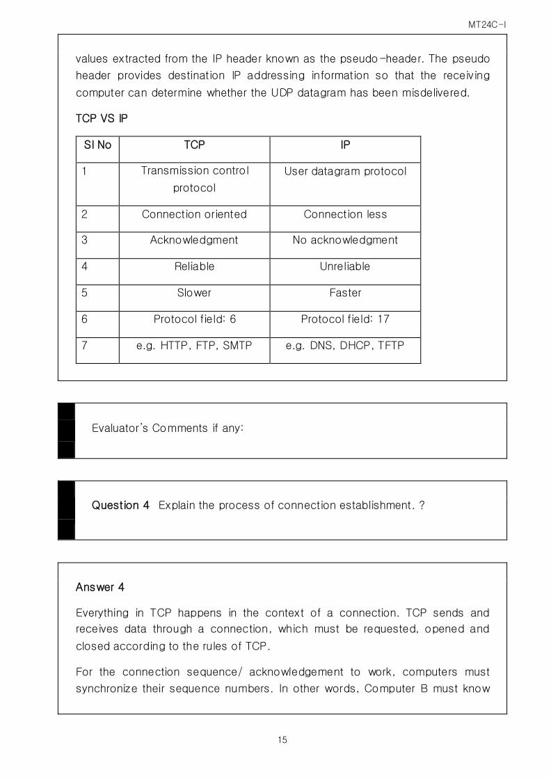
values extracted from the IP header known as the pseudo-header. The pseudo
header provides destination IP addressing information so that the receiving
computer can determine whether the UDP datagram has been misdelivered.
TCP VS IP
Sl No TCP IP
1 Transmission control
protocol
User datagram protocol
2 Connection oriented Connection less
3 Acknowledgment No acknowledgment
4 Reliable Unreliable
5 Slower Faster
6 Protocol field: 6 Protocol field: 17
7 e.g. HTTP, FTP, SMTP e.g. DNS, DHCP, TFTP
Evaluator’s Comments if any:
Question 4 Explain the process of connection establishment. ?
Answer 4
Everything in TCP happens in the context of a connection. TCP sends and
receives data through a connection, which must be requested, opened and
closed according to the rules of TCP.
For the connection sequence/ acknowledgement to work, computers must
synchronize their sequence numbers. In other words, Computer B must know

MT24C-I
16
what initial sequence number (ISN) Computer A used to start the sequence.
Computer A must know what ISN computer B will use to start the sequence for
any data computer B will transmit.
This synchronization of sequence numbers is called a three-way handshake.
The three-way (fig 6) handshake always occurs at the beginning of a TCP
connection. The three steps of a three way handshake are as follows:
Computer A sends a segment with
SYN = 1
ACK =0
Sequence Number = X ( where X is Computer A’s ISN)
Figure 6 Three way handshaking
The active open computer (Computer A) sends a segment with the SYN flag
set to 1 and the ACK flag set to 0. SYN in short for synchronize. This flag, as
described earlier, announces an attempt to open a connection. This first
segment header also contains the initial sequence number (SIN), which marks
the beginning of the sequence numbers for data that Computer A will transmit.
The first byte transmitted to Computer B will have the sequence number ISN+1.
Computer B receives Computer A ‘s segment and returns a segment with
SYN = 1 ( still in synchronization phase)
ACK = 1 ( the acknowledgement number field will contain a value)

MT24C-I
17
Sequence number = Y , where Y is Computer B’s ISN
Acknowledgment number = M+1, where M is the last sequence number
received from Computer A
Computer A sends a segment to Computer B that acknowledges receipt of
Computer B’s ISN:
SYN =0
ACK =1.
Sequence number = Next sequence number in series ( M+1)
Acknowledgment number = N +1( where N is the last sequence number
received from Computer B)
After the three-way handshake, the connection is open, and the TCP modules
transmit and receive data using the sequence and acknowledgment scheme
described earlier.
Active open
Side that sends the first SYN is said to perform an active open.
Passive open
Side which receives the SYN and sends the next SYN performs a passive open.
Simultaneous open
Each end transmits a SYN and the SYNs must pass each other on the network.
Only one connection results from this.
Evaluator’s Comments if any:
Question 5 What is I/O multiplexing?

MT24C-I
18
Answer 5
The socket addressing system enables TCP and UDP to perform another
important Transport layer task: multiplexing and demultiplexing. Multiplexing
is the act of braiding input from several sources into a single output, and
demultiplexing is the act of receiving input from a single source and
delivering it to multiple outputs (Fig 7).
Figure 7 Multiplexing and Demultiplexing
Multiplexing/demultiplexing enables the lower levels of the TCP/IP stack to
process data without regards to which application initiated that data. All
associations with the originating application are settled at the Transport
layer, and data passes to and from the Internet layer in a single, application
independent pipeline.
The key to multiplexing and demultiplexing is the socket address. Because
the socket address combines the IP Number with the port number, it
provides a unique identifier for a specific application on a specific machine.
All client machines use a well-known port address TCP 23 to contact the
Telnet server, but the destination socket for each of the connecting PCs is
unique. Likewise, all networks applications running on the Telnet server use
the server’s IP address, but only the Telnet service uses the socket
address, consisting of the server’s IP address plus port 23.

MT24C-I
19
Figure 8 The socket address uniquely identifies an application on a
particular server
Evaluator’s Comments if any:
Question 6 What is direct and indirect routing?
Answer 6
Figure 9 Multiplexing /Demultiplexing

MT24C-I
20
This diagram shows three examples of IP datagram delivery. The first
transmission (highlighted in green) shows a direct delivery between two
devices on the local network. The second (purple) shows indirect delivery
within the local network, between a client and server separated by a router.
The third shows a more distant indirect delivery, between a client on the
local network and a server across the Internet.
The overall job of the Internet Protocol is to transmit messages from higher
layer protocols over an internetwork of devices. These messages must be
packaged and addressed, and if necessary fragmented, and then they must
be delivered. The process of delivery can be either simple or complex,
depending on the proximity of the source and destination devices.
Datagram Delivery Types
Conceptually, we can divide all IP datagram deliveries into two general
types, shown graphically in Figure 9:
o Direct Datagram Deliveries: When datagrams are sent between two
devices on the same physical network, it is possible for datagrams to
be delivered directly from the source to the destination. Imagine that
you want to deliver a letter to a neighbour on your street. You
probably wouldn't bother mailing it through the post office; you'd just
put the neighbour’s name on the envelope and stick it right into his or her mailbox.
o Indirect Datagram Deliveries: When two devices are not on the same
physical network, the delivery of datagrams from one to the other is
indirect. Since the source device can't see the destination on its local
network, it must send the datagram through one or more intermediate
devices to deliver it. Indirect delivery is analogous to mailing a letter
to a friend in a different city. You don't deliver it yourself—you put it
into the postal system
. The letter journeys through postal system, possibly taking several intermediate steps, and ends up in your friend's neighbourhood,
where a postal carrier puts it into his or her mailbox.
Comparing Direct and Indirect Delivery
Direct delivery is obviously the simpler of these. The source just sends the
IP datagram down to its data link layer implementation. The data link layer
encapsulates the datagram in a frame that is sent over the physical network
MT24C-I
21
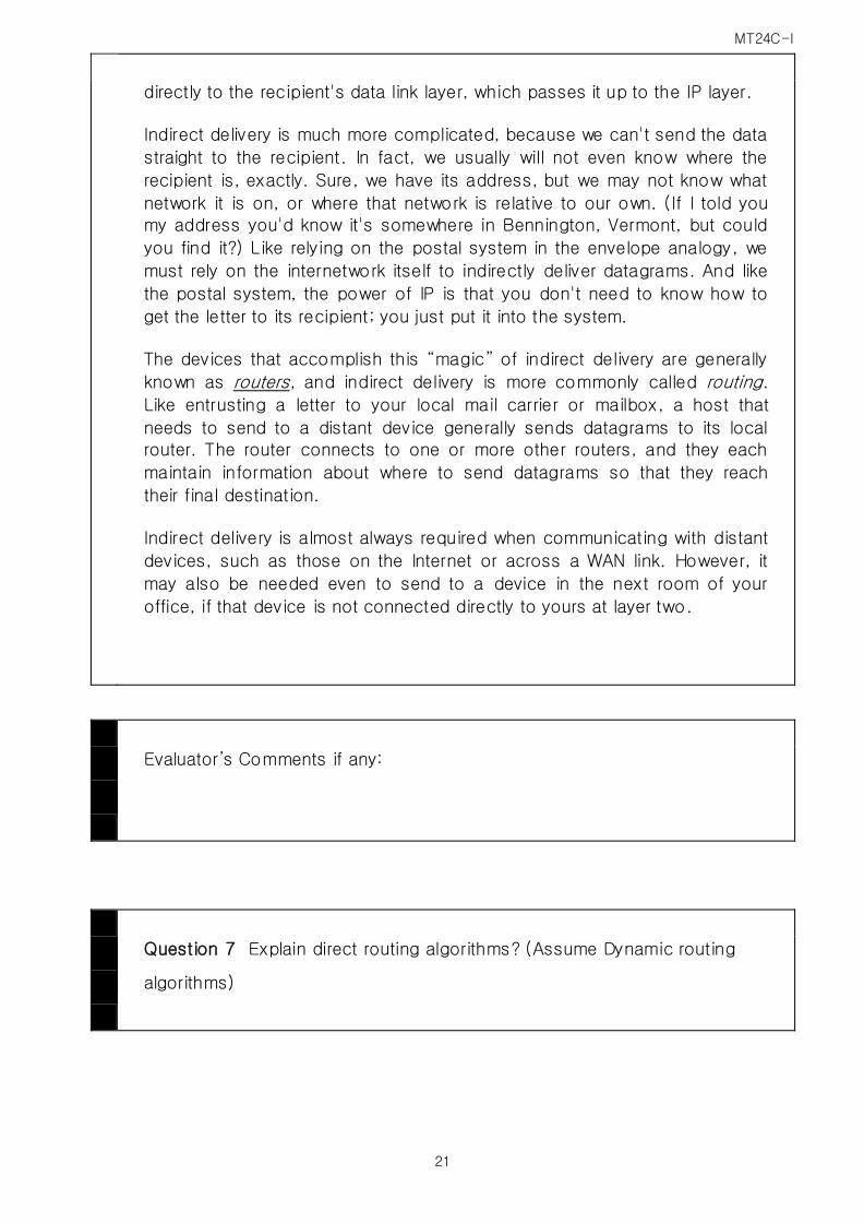
directly to the recipient's data link layer, which passes it up to the IP layer.
Indirect delivery is much more complicated, because we can't send the data
straight to the recipient. In fact, we usually will not even know where the
recipient is, exactly. Sure, we have its address, but we may not know what
network it is on, or where that network is relative to our own. (If I told you
my address you'd know it's somewhere in Bennington, Vermont, but could
you find it?) Like relying on the postal system in the envelope analogy, we
must rely on the internetwork itself to indirectly deliver datagrams. And like
the postal system, the power of IP is that you don't need to know how to
get the letter to its recipient; you just put it into the system.
The devices that accomplish this “magic” of indirect delivery are generally
known as routers, and indirect delivery is more commonly called routing.
Like entrusting a letter to your local mail carrier or mailbox, a host that
needs to send to a distant device generally sends datagrams to its local router. The router connects to one or more other routers, and they each
maintain information about where to send datagrams so that they reach
their final destination.
Indirect delivery is almost always required when communicating with distant
devices, such as those on the Internet or across a WAN link. However, it
may also be needed even to send to a device in the next room of your
office, if that device is not connected directly to yours at layer two.
Evaluator’s Comments if any:
Question 7 Explain direct routing algorithms? (Assume Dynamic routing
algorithms)

MT24C-I
22
Answer 7
Dynamic routing offers several advantages like it does not require human
intervention and it responses to changes in the network. Several algorithms
are used to produce these results. Important ones are:
Distance vector routing
Link state routing
Distance vector routing ( Bellman-ford routing) is an efficient and simple
routing method employed by many routing protocols. The underlying
philosophy of distance vector routing is that a router doenot need to know
the complete pathway to every network segment, it only needs to know in
which direction to send a datagram addressed to the segment( hence the
term vector). Routers using this algorithm attempt to optimize the pathway
by minimizing the number of routers that a datagram must cross. The
distance parameters is canned hop count.
Link state routing is a better alternative to distance vector routing. The
underlying philosophy is that every router attempts to build its own internal
map of the network topology. Each router periodically sends status
messages to the network. The router then builds the map of the network
topology. When it needs to send a datagram it chooses the best path. This
algorithm requires more processing.
Evaluator’s Comments if any:
Question 8 What is the difference b/w OSI Reference Model and TCP/IP
Reference Model?

MT24C-I
23
Answer 8
Figure 10 TCP/IP and OSI
Three concepts are central to the OSI model:
1. Services.
2. Interfaces.
3. Protocols.
Probably the biggest contribution of the OSI model is to make the distinction
between these three concepts explicit. Each layer performs some services
for the layer above it. The service definition tells what the layer does, not
how entities above it access it or how the layer works. It defines the layer's
semantics.
A layer's interface tells the processes above it how to access it. It specifies
what the parameters are and what results to expect. It, too, says nothing
about how the layer works inside.
Finally, the peer protocols used in a layer are the layer's own business. It
can use any protocols it wants to, as long as it gets the job done (i.e.,
provides the offered services). It can also change them at will without
affecting software in higher layers.
The TCP/IP model did not originally clearly distinguish between service,
interface, and protocol, although people have tried to retrofit it after the fact

MT24C-I
24
to make it more OSI-like. For example, the only real services offered by the
internet layer are SEND IP PACKET and RECEIVE IP PACKET.
As a consequence, the protocols in the OSI model are better hidden than in
the TCP/IP model and can be replaced relatively easily as the technology
changes. Being able to make such changes is one of the main purposes of
having layered protocols in the first place.
The OSI reference model was devised before the corresponding protocols
were invented. This ordering means that the model was not biased toward
one particular set of protocols, a fact that made it quite general. The
downside of this ordering is that the designers did not have much
experience with the subject and did not have a good idea of which functionality to put in which layer.
With TCP/IP the reverse was true: the protocols came first, and the model
was really just a description of the existing protocols. There was no problem
with the protocols fitting the model. They fit perfectly. The only trouble was
that the model did not fit any other protocol stacks. Consequently, it was not
especially useful for describing other, non-TCP/IP networks.
Another difference is in the area of connectionless versus connection-
oriented communication. The OSI model supports both connectionless and
connection-oriented communication in the network layer, but only connection oriented communication in the transport layer, where it counts
(because the transport service is visible to the users). The TCP/IP model has
only one mode in the network layer (connectionless) but supports both
modes in the transport layer, giving the users a choice. This choice is
especially important for simple request-response protocols.
Evaluator’s Comments if any:
Question 9 Draw and explain IP V-4 Packet format?
Answer 9
The Internet protocol (IP) is the host-to-host network layer delivery protocol

MT24C-I
25
for the Internet. IP is an unreliable connectionless datagram protocol- a
best effort delivery service. IP uses only an error detection mechanism and
discards the packet if it is corrupted.
IP is connectionless protocol for a packet-switching network which uses
the datagram approach. This means that each datagram is handled
independently and each datagram can follow a different route to the
destination and also arrive in a different order. It relies on upper level
protocol to take care of all these problems.
Figure 11 IPV4 packet format
Version (VER): This field defines the version of the IP. Currently the version
is 4 (IPv4). In the future it will be replaced by IPv6.
Header length (HLEN): Because of the option field, the length of the header
is variable. This field defines the length of the datagram header in 4-byte
words. Its value must be multiplied by 4 to give the length in bytes.
Checksum: The checksum in the IP packet covers only the header, not the
data. There are two good reasons for this. First, all higher level protocols
that encapsulate data in the IP datagram have a checksum field that covers
the whole packet. Therefore the checksum for the IP datagram does not
have to check the encapsulation data. Second, the header of the IP packet
changes with each visited router but the data does not. So the checksum
includes only the part that has changed.
Source Address: This field defines the IP address of the source. This field
must remain unchanged during the time the IP datagram travels from the
source host to the destination host.

MT24C-I
26
Destination address: This field defines the IP address of the destination.
This field must remain unchanged during the time the IP datagram travels
from the source host to the destination host.
Type of service: Specifies how an upper layer protocol would like a current
datagram to be handled, and assigns datagram various levels of
importance.
Total length: Specifies the length, in bytes, of the entire IP packet, including
the data and header.
Identification: Contains an integer that identifies the current datagram. This
field is used to help piece together datagram fragments.
Flags: consists of a 3-bit field of which the two low order bits control
fragmentation. The low order bit specifies whether the packet can be
fragmented. The middle bit specifies whether the packet is the last fragment
in a series of fragmented packets. The third or high order bit is not used.
Fragment offset: Indicates the position of the fragments data relative to the
beginning of the data in the original datagram, which allows the destination
IP process to properly reconstruct the original datagram.
Time-to-Live: maintains a counter that gradually decrements down to zero,
at which point the datagram is discarded. This keeps packets from looping
endlessly.
Protocol: Indicates which upper layer protocol receives incoming packets
after the IP processing is complete.
Options: There are optional and used for network testing and debugging.
Data: Contains upper layer information.
Evaluator’s Comments if any:
Question 10 Draw and explain TCP segment data format?

MT24C-I
27
Answer 10
The unit of transfer between the TCP software on two machines is called a
segment. Segments are exchanged to establish connections, transfer data,
send acknowledgements, advertise window sizes, and close connections.
Because TCP uses piggybacking, an acknowledgement traveling from
machine A to machine B may travel in the same segment as data traveling
from machine A to machine B. Figure 12 shows the TCP segment format.
Figure 12 TCP segment data format
Each segment is divided into two parts, a header followed by data. The
header, known as the TCP header, carries the expected identification and
control information.
Details:
SOURCE PORT (16 bits): The port number assigned to the application on the
source machine.
DESTINATION PORT (16 bits): The port number assigned to the application
on the destination machine.
Sequence number (32 bits): The sequence number of the first byte in this
particular segment, unless the SYN flag is set to 1. If the SYN flag is set to
1, the sequence number field provides the initial sequence number (ISN),
which is used to synchronize sequence numbers. If the SYN flag is set to 1,
the sequence number of the first octet is one greater than the number that
appears in this field( in other words, ISN+1)
ACKNOWLEDGEMENT NUMBER (32 bits): This field acknowledges a received
segment. It identifies the number of the octet that the source expects to

MT24C-I
28
receive next, in other words the sequence number of the last byte received
+1. Note that the sequence number refers to the stream flowing in the same
direction as the segment, while the acknowledgement number refers to the
stream flowing in the opposite direction from the segment.
Data offset (4 bits): A field that tells the receiving TCP software how long the
header is and, therefore, where the data begins. The data offset is
expressed as an integer number of 32-bits words.
Reserved (6 bits): Reserved for future use. This field provides room to
accommodate future developments of TCP and must all be zeros.
Control flags(1 bit each):
The control flags communicate special information about the segment
Figure 13 Bits of the CODE field in the TCP header
Window (16 bit): A parameter used for flow control. TCP software advertises
how much data it is willing to accept every time it sends a segment by
specifying its buffer size in the WINDOW field. The field contains a 16-bit
unsigned integer in network-standard byte order. The window defines the
range of sequence numbers beyond the last acknowledged sequence
number that the sending machine is free to transmit without further
acknowledgment.
Checksum (16 bit): A field used to check the integrity of the segment. A
receiving computer performs a checksum calculation based on the segment
and compares the value to the value stored in this field. TCP and UDP
include a pseudo-header with IP addressing information in the checksum
calculation.
Urgent pointer (16 bits): An offset pointer pointing to the sequence number
that marks the beginning of any urgent information.

MT24C-I
29
Options: Specifies one of a small set of optional settings.
Padding: Extra zero bits (as needed) to ensure that the data begins on a
32-bit boundary.
Data: The data being transmitted with the segment.
Evaluator’s Comments if any: