mt. shasta seismic monitoring improvements...
TRANSCRIPT

1
Proposal
Closing the Seismic Monitoring Gap at Mount Shasta Volcano
Shasta-Trinity National Forest, California
USGS California Volcano Observatory
February 2017
Objective Install three new seismograph stations on the flanks of Mt. Shasta that will provide improved volcanic unrest monitoring capability.
Background Mount Shasta is ranked as a Very High Threat volcano whose explosive behavior and lahar potential can impact both large populations and substantial development (USGS Open-File Report 2005-1164). The California Volcano Observatory (CalVO) is working with the California Office of Emergency Services (CalOES) and the California Geological Survey (CGS) to evaluate volcanic hazard exposure/vulnerability at a statewide level. The USGS will formally release a report in 2017—after a comment period—describing these hazards. It will also be inserted as an annex to the State of California CalOES Emergency Plan. The report presents a geospatial analysis of populations, infrastructure, natural resources, and human activities potentially at risk from future eruptions of the state's eight Moderate-, High-, and Very-High-Threat volcanoes. Our report will show that over 103,000 people live within Mount Shasta's volcano hazard zone and intermittent populations of over 30 million annually pass through the hazard zone on roadways (including Interstate 5) or while visiting popular state and federal recreation sites (the zone includes parts of Shasta-Trinity, Klamath, and Modoc National Forests). And potential damage to locally situated infrastructure from a Mount Shasta eruption can have statewide repercussions (e.g. high voltage transmission lines, water delivery systems).
In a nutshell, our exposure/vulnerability analysis shows that Mount Shasta is not a volcano to play "catch-up" with by hastily deploying temporary seismometers in the midst of volcanic unrest. The three proposed telemetered seismograph stations will provide much improved monitoring capability associated with the Mt. Shasta volcanic center, including: improved detection of smaller earthquakes (lower threshold of earthquake size means we see more earthquakes); improved ability to find and locate seismic tremor (which is indicative of magma movement); and improved hypocenter location (which leads to better understanding of where magma is moving in the system and differentiating between sources).

2
Proposal The USGS requests approval to install new state-of-the-art seismograph equipment co-located with existing geodetic instruments operated by UNAVCO, Inc. Details and proposed locations follow. The USGS proposes to install our equipment near—but just outside—the permitted footprint of the UNAVCO instrumentation at the 3 locations. Two locations are in previously disturbed areas (LBR and LGR), and one (LDL) will be in a previously undisturbed area but next to the disturbed ground surrounding the UNAVCO site. Station LGR will officially replace an existing seismic station (LGB) on the flank of Gray Butte. Upon completion of the installation of station LGR, USGS will remove the equipment at LGB and return the area to its natural state.
As you can see in Station Schematic Diagrams below, the footprint of the seismic site is roughly 5’ x 35’. Excavation will be done by hand except for the coring for the shallow boreholes which will be done by a pickup-truck-mounted (or similar sized vehicle) coring apparatus. Installation typically takes 2-3 days with a team of 4 people and 2-3 vehicles. Future station maintenance visits are conducted only when malfunctions occur or approximately every 5 years. Although the equipment enclosures will be secured by locks, USGS understands the risk of vandalism at these locations.
Regional Maps of Proposed Stations
Figure 1

3
Figure 2

4
Individual Site Details
Station Name: Dillon Ridge Site Code: LDL
Latitude: 41.38124º Longitude: -122.29383º Elevation: 5605ft
Geology: Bedrock basalt/andesite flow Vegetation: Manzanita scrub and
nearby ponderosa pine Proposed Equipment
Instrumentation: Datalogger: Quanterra Q330S, 6-ch; Sensors: Nanometrics Trillium 120PH (installed at 5’ depth), Kinemetrics Episensor EST (installed at surface)
Telemetry: Initial installation: Sierra Wireless RV-50 cellular gateway; Long term: Xetawave Xeta1 162-174MHz NTIA-licensed digital transceiver (max. 2W RF output power)
Power: approximately 160W photovoltaic solar panel array (~2’x4’); approximately 4x 100Ahr deep-cycle AGM-type batteries
Access: publically accessible location with no restrictions; last 3.75 miles of access road is unimproved dirt forest road through a tree plantation; 4WD not necessary except in wet or snowy conditions, but high-clearance is recommended Miscellaneous Notes: excellent sky view for solar; some vegetation will have to be removed to accommodate new enclosures (approximately the size of the site footprint); place new equipment within 50’ of existing UNAVCO GPS site; good cellular coverage because site overlooks Shasta City and I-5 corridor; small to moderate vandalism potential due to remoteness of site but unrestricted public access; solar panels and telemetry antennas will have to be above the expected high snow line (perhaps 6’), although, because the site sits on a small ridge, some snow wind shedding is possible;

5
Maps:
Figure 3

6
Figure 4

7
Station Schematic Diagram:
Figure 5

8
Photos:
Figure 6 – Looking southwest.
Figure 7 – Looking northeast.
9
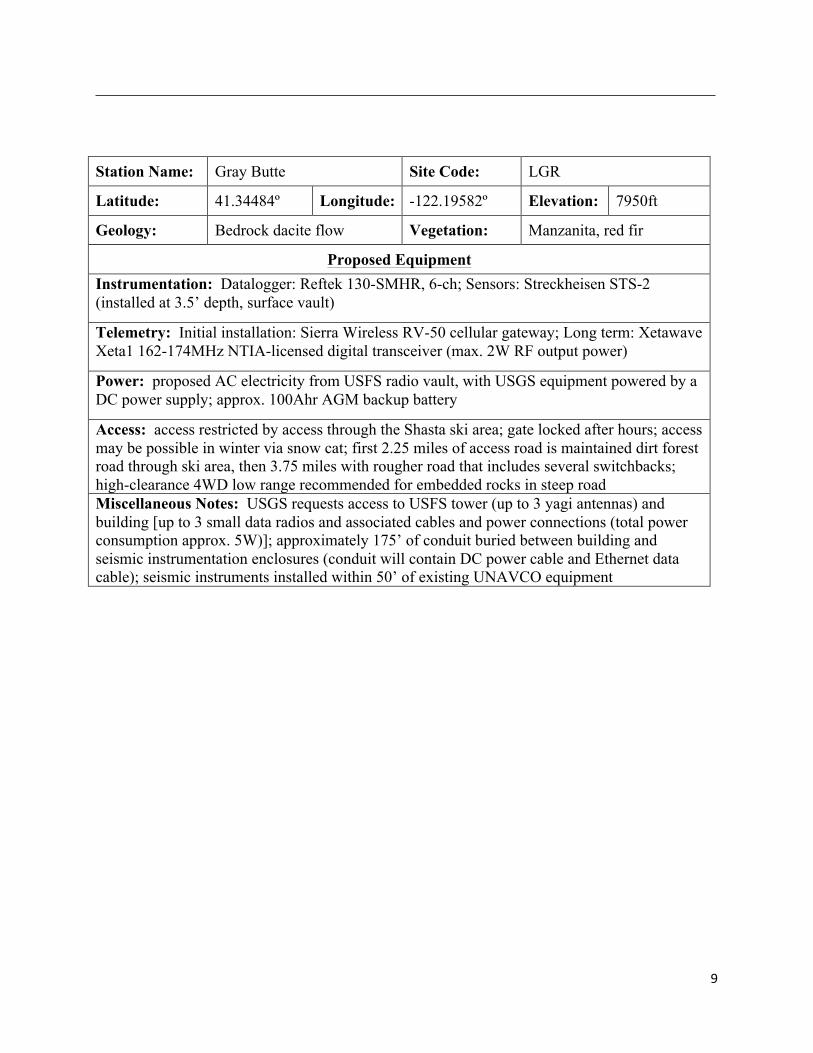
Station Name: Gray Butte Site Code: LGR
Latitude: 41.34484º Longitude: -122.19582º Elevation: 7950ft
Geology: Bedrock dacite flow Vegetation: Manzanita, red fir
Proposed Equipment Instrumentation: Datalogger: Reftek 130-SMHR, 6-ch; Sensors: Streckheisen STS-2 (installed at 3.5’ depth, surface vault)
Telemetry: Initial installation: Sierra Wireless RV-50 cellular gateway; Long term: Xetawave Xeta1 162-174MHz NTIA-licensed digital transceiver (max. 2W RF output power)
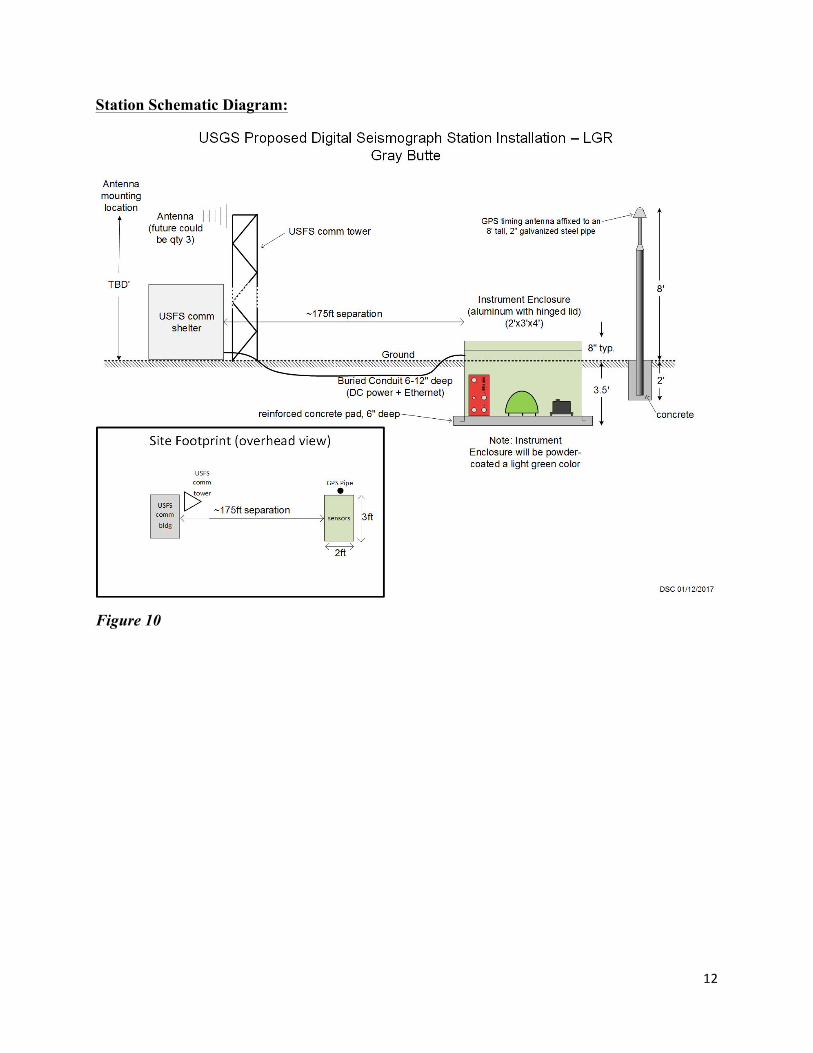
Power: proposed AC electricity from USFS radio vault, with USGS equipment powered by a DC power supply; approx. 100Ahr AGM backup battery
Access: access restricted by access through the Shasta ski area; gate locked after hours; access may be possible in winter via snow cat; first 2.25 miles of access road is maintained dirt forest road through ski area, then 3.75 miles with rougher road that includes several switchbacks; high-clearance 4WD low range recommended for embedded rocks in steep road Miscellaneous Notes: USGS requests access to USFS tower (up to 3 yagi antennas) and building [up to 3 small data radios and associated cables and power connections (total power consumption approx. 5W)]; approximately 175’ of conduit buried between building and seismic instrumentation enclosures (conduit will contain DC power cable and Ethernet data cable); seismic instruments installed within 50’ of existing UNAVCO equipment

10
Maps:
Figure 8

11
Figure 9
12
Station Schematic Diagram:
Figure 10

13
Photos:
Figure 11 – Looking south from commercial communications site.
Figure 12 – Looking north-northwest from proposed site area back towards the commercial communications site and the USFS tower and building.
14
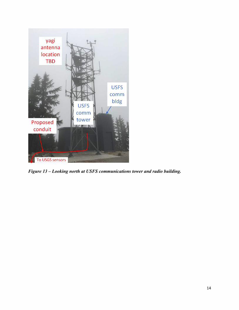
Figure 13 – Looking north at USFS communications tower and radio building.

15
Station Name: Brewer Creek Site Code: LBR
Latitude: 41.40959º Longitude: -122.06766º Elevation: 5287ft
Geology: Unknown depth to bedrock; mix of ash and sand; very loose surface
Vegetation: Open meadow (disturbed) surrounded by ponderosa pine and red fir forest
Proposed Equipment Instrumentation: Datalogger: Quanterra Q330S, 6-ch; Sensors: Nanometrics Trillium 120PH (installed at 20’ depth), Kinemetrics Episensor EST (installed at surface)
Telemetry: Xetawave Xeta1 162-174MHz NTIA-licensed digital transceiver (max. 2W RF output power); 30’ tall lattice tower (18” face), antenna at top, solar array just below
Power: approximately 280W photovoltaic solar panel array (~4’x4’); approximately 6x 100Ahr deep-cycle AGM-type batteries
Access: publically accessible location with no restrictions; Forest Road 19 is wide well-maintained gravel road suitable for any vehicle; last 0.5 miles of access road is unimproved dirt forest road almost flat; 4WD not necessary except in wet or snowy conditions Miscellaneous Notes: somewhat restricted sky view for solar due to forest; ponderosa saplings within 50’ of the equipment should be removed to allow for continued sky view for solar power and to reduce wind-induced seismic noise; place new equipment within 100’ of existing UNAVCO GPS site; no cellular coverage; thick forest will require VHF radio telemetry to Black Fox Mt.; small to moderate vandalism potential due to remoteness of site but unrestricted public access; lattice tower required to raise solar panels and telemetry antennas 5’ above the expected high snow line (site sits in a low area that likely holds snow, perhaps 25-30’?—need to research); nearby Brewer Creek has cut up to 6’ deep into the ash and sand terrain exposing cobbles but no apparent bedrock, thus the proposed deep sensor installation; the meadow area here has been disturbed by former logging operations; may want to consider using a posthole Episensor installed at 20’ depth due to loose top soil (this would mean installing one sensor on top of the other)

16
Maps:
Figure 14

17
Figure 15

18
Station Schematic Diagram:
Figure 16

19
Photos:
Figure 17 – Looking southeast.
Figure 18 – Looking north towards the access road.

20
Photo Examples of Instrumentation (from Existing Sites)
Figure 19 - Typical example of equipment enclosures at all sites, and the solar/antenna mast at proposed station LDL. The sensor vault is on the left and battery/radio vault is on the right. Station LDL will probably have a similar height mast, but the solar panel(s) will be mounted up a little higher. There is no proposed solar/antenna mast at LGR (with permission to use USFS tower and comm shelter), and an example of the proposed mast at LBR is shown in Figure 20.

21
2.
Figure 20 - An example of the proposed solar/antenna mast at station LBR. This photo is from Lassen National Forest. The tall mast is meant to keep the solar panels and radio antenna above a typical high snow accumulation.