mslab.book(mslab create 3d utility graphics.fm)
TRANSCRIPT

Colorado Department of Transportation Page 189
LAB 8 - Create 3D Utility Graphics
In this example, you’ll create a Utility model file, work with references, and then place proposed 3D utility lines using the CDOT Menu and the parallel copy tool. You’ll also modify the graphics as necessary.
Chapter Objectives:
After completing this exercise you will know how to:
Work with nested references
Use the Copy Attachment option for references
Use the CDOT Menu to place custom line styles (Utility lines).
Place elements in 3D using Depth Lock Manipulate elements using the Parallel Copy tool
Modify elements using the Trim tools
Lab 8.1 - Create the Utility Model File
1. Open the MicroStation Manager and set the Project to 12345.
2. Set the directory to \Utilities\Drawings\Reference Files.
3. Open the file 12345UTIL_Model.dgn. The blank Utility model file opens.
4. Select File > Save As...
5. Set the Directory to \Utilities\Working.
Page 190 Colorado Department of Transportation
LAB 8 - Create 3D Utility Graphics Labs for MicroStation V8i SS2
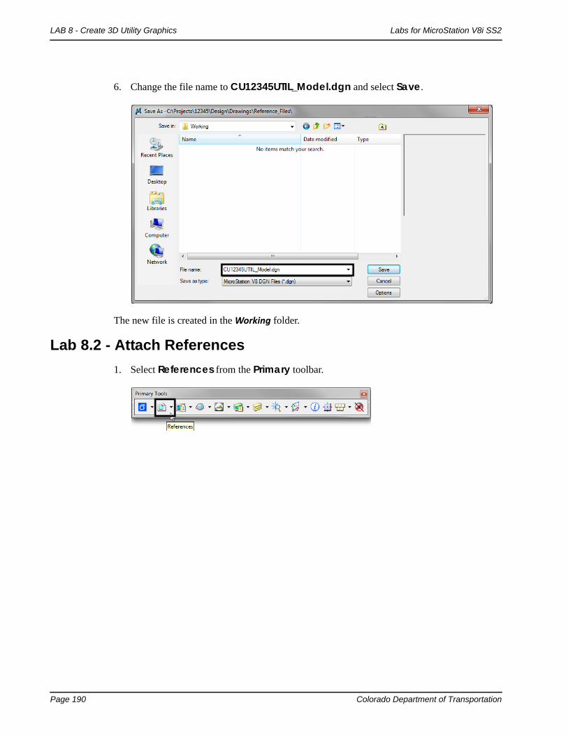
6. Change the file name to CU12345UTIL_Model.dgn and select Save.
The new file is created in the Working folder.
Lab 8.2 - Attach References
1. Select References from the Primary toolbar.

Colorado Department of Transportation Page 191
Labs for MicroStation V8i SS2 LAB 8 - Create 3D Utility Graphics
2. From the References dialog box, select Tools > Attach and select the 12345DES_Model.dgn file from the \Design\Drawings\Reference Files folder.
3. Verify the Attachment Method is set to Interactive and select Open.

Page 192 Colorado Department of Transportation
LAB 8 - Create 3D Utility Graphics Labs for MicroStation V8i SS2
4. In the Attachment Settings box, keyin a Logical Name of Design and a Description of Design Model Plan. Make sure Display Raster Reference is on. Set the other options as shown and select OK.
5. Fit the view.
The Design reference graphics, along with the raster photos, appear in the Utility model file.
Lab 8.3 - Raster Images
Since Display Raster References was turned on when attaching the reference, the aerial photos were attached with the design model file (they were turned on in the Design Model file from the last lab). You can quickly turn them off from the Reference dialog instead of opening the Raster Manager.

Colorado Department of Transportation Page 193
Labs for MicroStation V8i SS2 LAB 8 - Create 3D Utility Graphics
1. In the References box, highlight the Design reference and toggle Display Raster Refer-ences off.
Lab 8.4 - Work with Reference Files
1. Window in on the Intersection.

Page 194 Colorado Department of Transportation
LAB 8 - Create 3D Utility Graphics Labs for MicroStation V8i SS2
2. On the Reference dialog, change No Nesting to Live Nesting and set Depth to 1.
3. In the Hierarchy pane, select the Design reference file as shown below. On the right, select the Survey/Topo nested reference and make sure that Display is toggled on.

Colorado Department of Transportation Page 195
Labs for MicroStation V8i SS2 LAB 8 - Create 3D Utility Graphics
4. Open the Level Display box, make sure the Show Target Tree button is On, and select the Survey/Topo Reference. Right click on the bottom pane and choose All On to turn on all reference levels.
The nested Survey/Topo graphics are displayed.
5. Back in the Reference dialog box, select the upper-level CU12345UTIL_Model.dgn master file in the Hierarchy pane. On the right, select the 12345DES_Model.dgn reference and toggle off Display.
Both Design and Survey/Topo are turned off since Survey/Topo is nested.
6. Turn the display of the Design reference back On.

Page 196 Colorado Department of Transportation
LAB 8 - Create 3D Utility Graphics Labs for MicroStation V8i SS2
7. How would you turn off the Design graphics and leave the Survey/Topo graphics on? Currently, as nested references, you can’t do this. However, in the next section you will accomplish this using Copy Attachments.
Use the Copy Attachments Option
Many times, especially in Model files, you want all your references to be upper level references (as opposed to nested references) so that you can turn on/off the display of individual reference files. To accomplish this you can either reference all the nested files one by one or you can use the Copy Attachments option.
1. With the Design reference selected on the right, change the Live Nested option to Copy Attachments.
Note: Notice that in the Hierarchy pane of the References dialog box both the Design and the Survey/Topo references are now upper level references. As a result of changing Live Nesting to Copy Attachments, the nested Survey/Topo reference was copied in as a direct attachment.

Colorado Department of Transportation Page 197
Labs for MicroStation V8i SS2 LAB 8 - Create 3D Utility Graphics
2. On the right-hand side of the References box, select the reference for the Design model and toggle the Display off.
With both references as direct attachments, each reference can be individually turned on/off. In this example the Design reference is turned off while the Survey/Topo graphics remain on.
Note: As a rule of thumb for Model files, you can reference nested to avoid having to attach multiple times. Then, once the nested references are attached, use the Copy Attachments option to make all nested references direct attachments. For Sheet files (see Chapter 9), you should typically use nested attachments.

Page 198 Colorado Department of Transportation
LAB 8 - Create 3D Utility Graphics Labs for MicroStation V8i SS2
3. Turn the Design reference display back On.
Lab 8.5 - Drawing in 3D (Using ACS Plane Snap Lock)
In the next series of steps, you will practice placing utility graphics from the CDOT Menu with and without ACS Plane Snap lock. The ACS Plane Snap lock sets the elevation of the graphics are placed in a 3D file.
Place overhead electrical lines
1. To check your active depth, key in az=$ then <D> in the view.
The default active depth for the CDOT for the Utility model file is 0.00.
Select the Locks button on the status bar and verify that ACS Plane Snap lock is turned Off.
With ACS Plane Snap lock turned off, you will pick up the elevation of elements you snap to in a 3D file.

Colorado Department of Transportation Page 199
Labs for MicroStation V8i SS2 LAB 8 - Create 3D Utility Graphics
2. Zoom in on the south side of the intersection cross road.
3. On the CDOT Menu highlight the Utilities group and set Status to Proposed.
4. Select the Electric category.
5. Set the Filters category to All.
6. Select the Overhead Line item.
Note that the active level is automatically set to UTIL_ELECTRICAL_Overhead and the Place SmartLine command is started.

Page 200 Colorado Department of Transportation
LAB 8 - Create 3D Utility Graphics Labs for MicroStation V8i SS2
7. AccuSnap to the end of the existing North/South overhead line at the power pole as shown.
8. AccuSnap to the end of the existing east/west overhead line at the power pole as shown.
9. <R> to complete this line.
10. Turn Off the display of the Topo/Survey reference to better see the proposed graphics.

Colorado Department of Transportation Page 201
Labs for MicroStation V8i SS2 LAB 8 - Create 3D Utility Graphics
11. <T> on the end of the proposed overhead electrical line you just placed.
Note: Even though the active depth is 0, since Depth lock is turned off the line was placed at the elevation of the existing overhead line (6627.317).
12. <T> on the other end of the proposed overhead electrical line to check its elevation.
Place proposed gas lines
1. Turn Off the display of the Design reference and turn On the display of the Survey/Topo reference.
2. On the CDOT Menu, select the Gas category.

Page 202 Colorado Department of Transportation
LAB 8 - Create 3D Utility Graphics Labs for MicroStation V8i SS2
3. Select the Gas Line item.
4. <T> on the end of the existing gas line on the east side of the road.
5. Place data points to draw the gas line in the approximate location shown.
6. <R> when done.

Colorado Department of Transportation Page 203
Labs for MicroStation V8i SS2 LAB 8 - Create 3D Utility Graphics
Note: The line does not look as expected. <T> on the East end of East-West section of the newly placed gas line and note the elevation.
<T> on the West end and note the elevation
<T> snapping to an existing element positions the starting point of the new element at the elevation of the original element. Subsequent points that are not snapped to are placed at the Active Depth (Elevation) of 0. In this case, what you see is a proposed gas line that goes from an elevation of +/- 6622 to an elevation of 0 making the utility much longer than it should be. Because there are now so many “G” symbols in a line that is over 6000’ long, it gives the appearance of a thick line.
7. Delete the proposed gas utility line you just placed.
8. Select the Locks from the status bar.
9. Toggle On ACS Plane Snap Lock.

Page 204 Colorado Department of Transportation
LAB 8 - Create 3D Utility Graphics Labs for MicroStation V8i SS2
10. On the Snap Mode toolbar, toggle AccuSnap Off.
Note: AccuSnap doesn’t work consistently when Depth Lock is on. Therefore, to ensure Depth lock works correctly, toggle AccuSnap off.
11. Place the proposed gas line again by a <T> on the end of the existing gas line and then placing the other data points in the approximate location shown.
12. <T> anywhere on the proposed gas line you just placed and note the elevation.
Since ACS Plane Snap lock is on, the proposed gas line was placed at an elevation of 0.
Note: To return to the default settings, turn ACS Plane Snap lock Off and toggle AccuSnap back On.
Place fiber optic lines using parallel copy
Follow the steps below to place a fiber optic line by copying parallel an existing telephone line.
Locate reference graphics for copying
1. Turn off the TOPO_TERRAIN_Break-Lines level in the SurveyTopo reference.

Colorado Department of Transportation Page 205
Labs for MicroStation V8i SS2 LAB 8 - Create 3D Utility Graphics
2. Window in on the existing overhead electrical line in the southeast quadrant of the intersection as shown.
3. Select the Move Parallel tool from the Main task toolbar.
4. In the Tool Settings box, set the options as shown below.
5. <D> on the existing overhead line
6. Move the cursor down to specify the direction of the parallel copy.

Page 206 Colorado Department of Transportation
LAB 8 - Create 3D Utility Graphics Labs for MicroStation V8i SS2
7. <D> to place the copy.
Note: When copying graphics from a Topo file, elements will maintain a hard coded linestyle scale and thus appear at the incorrect scale. This scale needs to be adjusted using the Element Info tool. In this example the linestyle scale of the new utility line need to be changed from a value of 100 to 1.
8. Select the new graphic and <D> on the Element Info tool.
9. Expand the Extended category and Line Style Parameters sub-category.
10. Change the value of the Scale option to 1.
11. Close the Element Info

Colorado Department of Transportation Page 207
Labs for MicroStation V8i SS2 LAB 8 - Create 3D Utility Graphics
Change element attributes
Change the overhead electrical line to an underground fiber optic line using the Change Element Attributes command.
1. Set the active level to UTIL_FIBEROPTICS (hint: use a filter to help you set the level).
2. Select the Change Element Attributes command from the Main task toolbar.
3. Set Method to Change.
4. Toggle On Use Active Attributes.
5. Toggle On Level (this picks up the active level).
6. <D> on the overhead electrical line you just copied as the element to change.

Page 208 Colorado Department of Transportation
LAB 8 - Create 3D Utility Graphics Labs for MicroStation V8i SS2
7. <R> when done.
Since the Use Active Attributes option was turned on, the element was changed to the active level UTIL_FIBEROPTICS.
Set the elevation
1. <T> on the fiber-optics line you just placed.
The proposed fiber-optics line is in the 6615 elevation range (your exact elevation may be vary depending on where you placed a tentative point). This elevation is wrong for the fiber optic line since you copied the overhead electrical line. For now, you can set the elevation of this line to 0 and later, it can be placed as a feature in the InRoads surface at the correct elevation. One way to set the elevation of an element is to use the ModElev command on the CDOT Menu.
2. On the CDOT Menu, select CDOT Tools > ModElev.

Colorado Department of Transportation Page 209
Labs for MicroStation V8i SS2 LAB 8 - Create 3D Utility Graphics
3. In the ModElev tool settings box, set the elevation to 0.
4. Select Single (to identify a single element).
5. <D> on the new fiber-optics line you created.
6. <D> to accept.
7. <R> when done.
8. <T> on the fiber-optics line to check its elevation.
The Z value is now at 0. Use the ModElev command to easily set the elevation of any element or group of elements (selected with a fence).
Trim graphics
The new fiber optic line is only going in on the east side of the intersection cross road. Follow the steps below to use the Extend Element to Intersection command to trim the fiber optic graphics.
1. Select the Trim to Element tcommand from the Main task toolbar.
2. <D> on the fiber optic line to the right of the intersection, this is the section we wish to keep.

Page 210 Colorado Department of Transportation
LAB 8 - Create 3D Utility Graphics Labs for MicroStation V8i SS2
3. <D> on the north/south proposed overhead electrical line as the cutting element.
The fiber-optics lines are trimmed as shown.
4. Turn off the display of the Survey/Topo references.
5. Fit the view.
Only the proposed gas, electric and fiber-optic utility graphics should appear in the CU12345UtilityModel01.dgn file.

Colorado Department of Transportation Page 211
Labs for MicroStation V8i SS2 LAB 8 - Create 3D Utility Graphics
6. Turn the display of the Design reference On and window into the intersection as shown.
Move the utility model to the Reference Files folder
Move the utility model so that other groups can reference your work.
1. Select File > Save As and set the directory to the project’s \Utilities\Drawings\Reference_Files folder.
2. Remove the CU initials from the file name and select Save.

Page 212 Colorado Department of Transportation
LAB 8 - Create 3D Utility Graphics Labs for MicroStation V8i SS2
The file is saved to the new location.
Note: The project template delivers standard dgn’s for model and sheet files as starter files. Use caution when prompted to confirm saving over an existing file as you could lose data.
3. Select File > Close.
4. In the MicroStation Manager verify that the file was saved to the Reference_Files folder.
5. Set the directory to \Utilities\Working.
6. Right-click while hovering over the file and select Delete to delete the file from the Working folder.
7. Cancel the MicroStation Manager to exit.