msk thesis
TRANSCRIPT
A DGPS/Radiobeacon Receiverfor Minimum Shift Keying with
Soft Decision Capabilities
Tim Wescott www.wescottdesign.com
A DGPS/Radiobeacon Receiver for Minimum Shift Keying with Soft Decision Capabilities 2
Tim Wescott www.wescottdesign.com
A DGPS/Radiobeacon Receiver for Minimum Shift Keying with Soft Decision Capabilities 3
A DGPS/Radiobeacon Receiverfor Minimum Shift Keying with
Soft Decision Capabilities
The Global Positioning System (GPS) is now in operation, and many improvements to its performance are being sought. One such improvement is Differential GPS (DGPS), where known errors in the GPS broadcast are identified and the corrections broadcast to the end user [12]. One implementation of DGPS being considered is the use of coastal marine radio direction finding (RDF) radiobeacons in the 285-325kHz band as transmitters for the DGPS broadcast. The normal RDF beacon signal consists of a continuous carrier on a one kilohertz boundary plus a Morse-code identification signal 1025Hz above the carrier. In the DGPS/radiobeacon implementation proposed for the US coastal regions, the the differential data link signal uses minimum shift keying (MSK) at a data rate of 25, 60,100, 200, or 400 baud (the exact baud rate has not yet been decided). This MSK signal is centered between the RDF beacon carrier and identification signal.At the frequencies that these radiobeacons are operated, the prevailing atmospheric noise is both non-Gaussian and very strong. This noise characteristic makes the design of a long-range data link difficult. One solution that has been proposed is the use of forward error correction (FEC) coding of the data. The performance of FEC decoders can be improved by the use of a soft decision receiver, which delivers both bit decisions and information about the validity of the bit decisions [15].This work describes the design of a radio receiver for DGPS/radiobeacon service which is capable of reception of 400 baud MSK in the DGPS/radiobeacon band. The receiver is designed to be easily augmented to provide soft decisions and easily modified to receive MSK at data rates of 25 to 400 baud. The radio is a microprocessor controlled dual conversion superheterodyne with an audio frequency of 1kHz. The demodulator runs on the same microcomputer that controls the radio. The weak-signal performance of the demodulator is very good: the vs. bit error rate performance of the demodulator is only a couple of dB worse than the theoretical performance of differential phase-shift keying. The radio has a noise floor of -114dBm referenced to its 500Hz wide audio bandwidth and a 3rd order inter modulation intercept of +7dBm for a dynamic range of 83dB,This work concludes with a thumbnail analysis of the operations needed to implement a soft bit decision estimator, and some suggestions for the implementation of said soil bit decision estimator.
Tim Wescott www.wescottdesign.com

A DGPS/Radiobeacon Receiver for Minimum Shift Keying with Soft Decision Capabilities 4
PrefaceThe Story of the Web Edition
This Master's Thesis is a companion to a radio receiver that I built for Per Enge, then of Worcester Polytechnic Institute in Worcester, Massachusetts, in 1989 and 1990. The motivation for the receiver on Per's part was to get his hands on something that would receive the then-experimental US Coast Guard differential GPS data link broadcasts. Per needed a radio receiver that would not only receive MSK at the correct frequency, but would make “soft” decisions, so that he and his team of graduate students could experiment with advanced forward-error-correction decoding schemes. I needed a thesis topic.
My search for a thesis advisor was a well-thought out, highly detailed study. Basically, I took a list of all the electrical engineering faculty at WPI that had anything remotely to do with communications equipment, and I went knocking on doors. Fortunately for both Per and I, his was the first office on my list that was occupied. I explained that I was looking for a thesis topic that would involve communications equipment, preferably radio. He pulled out a schematic of a radio receiver and said “can you build something like this?”
I had reservations about the radio he wanted me to build. As I found out much later, he had reservations about my ability to build a radio. But the project worked out well for both of us – I got to build a radio receiver for my Master's Thesis and I got some excellent training in writing book-length documents. Per got what turned out to be only the second receiver designed for USCG DGPS radio beacon service. The receiver served him well for several years, and in the end I was fortunate enough to get it back to add to my collection.
When I wrote down this Master's Thesis, I thought I was doing it to check off a box in my graduation requirements, to learn a bit about writing really long (and even slightly scholarly) documents, and to make my Thesis advisor happy. I kept a copy of it on my bookshelf mostly out of pride, although I did have occasion to refer to one or two tidbits contained within. I assumed that I had wrung all of the use out of it that it was ever going to get.
Then, 15 years after it was written, I started coming across queries on USENET asking how to design and construct MSK receivers. People wanted to build MSK receivers, but were unable to find information on how to do the job. After some fruitless web searches, I decided that since I'd already done it once I should write a comprehensive article on the design and construction of an MSK receiver. After re-reading my Master's thesis, I decided that I already had, and all I needed to do was to post it to the web.
I solicited help on USENET, and Joel Kolstad, KE7CDV, kindly stepped forward and scanned my entire thesis into electronic form. Since that time, this thesis has been popular enough reading that we have run the whole thing through OCR software, turning it into text, and have made it into a document that is (hopefully) more readable than the original scanned-in version.
Keep in mind as you read this that the methods presented in this document are just one way to implement an MSK receiver. I designed this receiver and it worked, but I would never, ever suggest that it is the optimal design – in fact, many of the central design decisions of this radio
Tim Wescott www.wescottdesign.com
A DGPS/Radiobeacon Receiver for Minimum Shift Keying with Soft Decision Capabilities 5
were made late at night under intense schedule pressure by a neophyte engineer. So read it for the basic theory and as an example of how one such radio was built, but don't assume that it can't be vastly improved upon.
Tim Wescott www.wescottdesign.com
A DGPS/Radiobeacon Receiver for Minimum Shift Keying with Soft Decision Capabilities 6
Table of Contents1 Introduction.............................................................................................................................................6
1.1 The Global Positioning System.......................................................................................................61.2 DGFS and Radiobeacons.................................................................................................................71.3 Minimum Shift Keying...................................................................................................................81.4 Atmospheric Noise and Forward Error Correction.........................................................................81.5 Side Information..............................................................................................................................81.6 Outline of Thesis.............................................................................................................................8
2 The Radio.............................................................................................................................................102.1 The Mixing Scheme.....................................................................................................................102.2 The Local Oscillator.....................................................................................................................122.3 Front end Circuitry.......................................................................................................................14
2.3.1 Antenna Coupler...................................................................................................................142.3.2 RF filter, Mixer.....................................................................................................................152.3.3 IF preamp..............................................................................................................................15
2.4 IF Filter.........................................................................................................................................162.5 IF Amplifier..................................................................................................................................162.6 2nd Mixer and 2nd Local Oscillator.............................................................................................172.7 Audio Amplifier and AGC Amplifier...........................................................................................172.8 Microprocessor.............................................................................................................................17
2.8.1 The MC68HC11...................................................................................................................173 The Demodulators................................................................................................................................19
1.7 MSK..............................................................................................................................................203.1.1 MSK Detection.....................................................................................................................233.1.2 Synchronization....................................................................................................................24
3.2 Microprocessor based demodulator..............................................................................................253.3 The Timing Recovery Algorithm..................................................................................................26
3.3.1 Phase error estimation...........................................................................................................293.3.2 The gain blocks.....................................................................................................................293.3.3 Loop Filter Calculations and Bandwidth..............................................................................323.3.4 Limit Cycles..........................................................................................................................333.3.5 Lock Acquisition...................................................................................................................343.3.6 Carrier Stability and Carrier l\Loop Bandwidth...................................................................34
3.4 The Correlation Detector..............................................................................................................364 Tests of Radio Performance.................................................................................................................39
4.1 Bit error rate in the presence of Gaussian noise...........................................................................394.2 BER in the presence of an interfering carrier...............................................................................434.3 3rd Order Inter modulation Performance.....................................................................................454.4 Receiver Noise Floor....................................................................................................................47
5 Summary, Some Comments on Soft Bit Decisions, and Further Work...............................................495.1 Summary......................................................................................................................................495.2 Some Comments on Soft Bit Decisions.......................................................................................49
5.2.1 The Auxiliary Channel Method............................................................................................49
Tim Wescott www.wescottdesign.com
A DGPS/Radiobeacon Receiver for Minimum Shift Keying with Soft Decision Capabilities 7
5.2.2 The In-Channel Method........................................................................................................495.3 Suggestions for Further Work......................................................................................................52
1 Appendix A...........................................................................................................................................541.1 The Continuous-time MSK Demodulator.....................................................................................54
2 Appendix B...........................................................................................................................................572.1 Receiver Software.........................................................................................................................57
3 Appendix C...........................................................................................................................................873.1 Transmitter Software.....................................................................................................................87
4 Appendix D.........................................................................................................................................1044.1 Schematics...................................................................................................................................105
5 Bibliography........................................................................................................................................111
Tim Wescott www.wescottdesign.com
A DGPS/Radiobeacon Receiver for Minimum Shift Keying with Soft Decision Capabilities 8
1 Introduction
1.1 The Global Positioning SystemThe Global Positioning System (GPS) is a worldwide real-time navigation system, currently being developed by the Department of Defense, that will broadcast ranging signals from a constellation of 24 satellites. Various mechanisms limit the accuracy of users' range measurements and ultimately their position determinations. These mechanisms include some errors that vary rapidly in time and space, and others that vary slowly. The slowly varying errors include unmodeled ionospheric delay and "selective availability", which is intentionally introduced for purposes of national defense. Slowly varying errors can be corrected using differential techniques, providing a channel is available to convey the differential correction information to users.
Differential GPS (DGPS) requires a local reference station, a communication link to users, and user GPS receivers [12]. The reference station has its own high quality GPS receiver that continuously measures range to all satellites in view, and determines local range errors using its known surveyed location. Corrections for the local errors arc then communicated to users, who remove the errors from the ranging information determined by their own GPS receiver. Civilian users can improve their position fixing accuracy from 100 meters to better than 30 meters using differential corrections, making DGPS potentially suitable for many precision civilian navigation applications.
Tim Wescott www.wescottdesign.com
A DGPS/Radiobeacon Receiver for Minimum Shift Keying with Soft Decision Capabilities 9
1.2 DGFS and Radiobeacons
The US Coast Guard maintains and operates a system of marine radiobeacons, located along the Atlantic, Gulf and Pacific coasts and on the Great Lakes [4]. These radiobeacons provide a 2-line fix capability out to 50 nautical miles or the 100 fathom curve, whichever is greater. They operate in the 285-325 kHz band, with a nominal channel spacing of 1kHz. Similar radiobeacons are operated by various European countries at a channel spacing of 1kHz, which is currently being reduced to 500Hz [6].
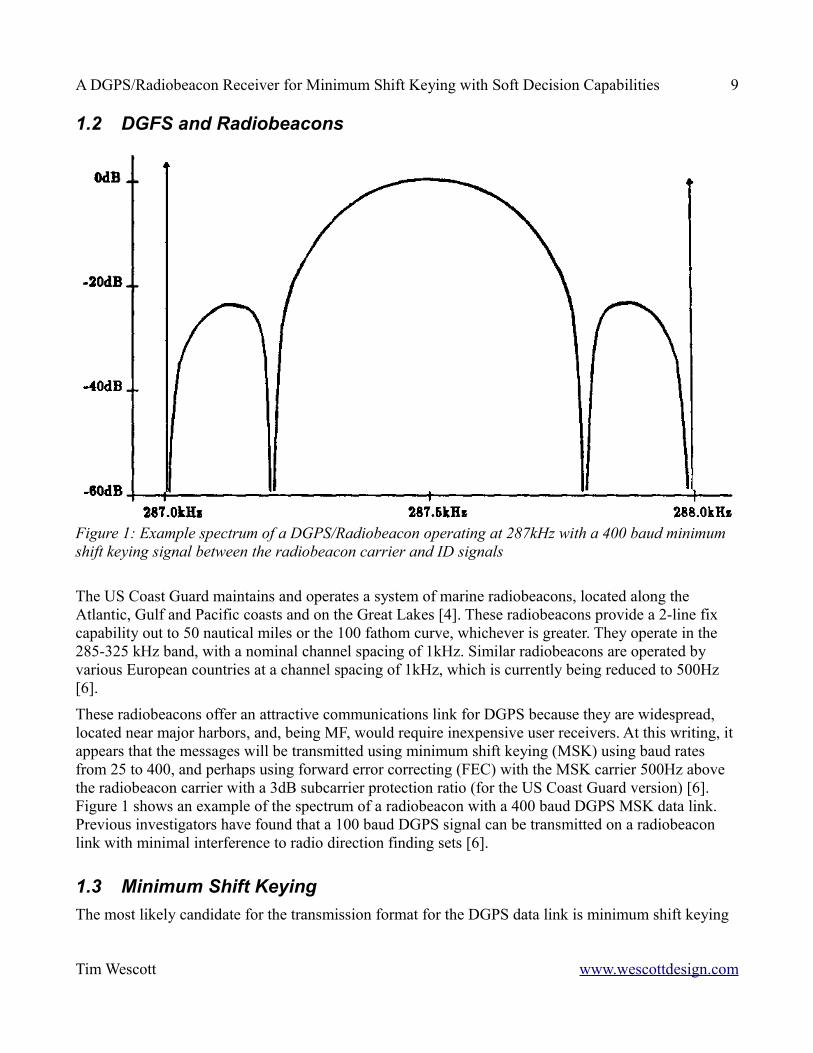
These radiobeacons offer an attractive communications link for DGPS because they are widespread, located near major harbors, and, being MF, would require inexpensive user receivers. At this writing, it appears that the messages will be transmitted using minimum shift keying (MSK) using baud rates from 25 to 400, and perhaps using forward error correcting (FEC) with the MSK carrier 500Hz above the radiobeacon carrier with a 3dB subcarrier protection ratio (for the US Coast Guard version) [6]. Figure 1 shows an example of the spectrum of a radiobeacon with a 400 baud DGPS MSK data link. Previous investigators have found that a 100 baud DGPS signal can be transmitted on a radiobeacon link with minimal interference to radio direction finding sets [6].
1.3 Minimum Shift KeyingThe most likely candidate for the transmission format for the DGPS data link is minimum shift keying
Tim Wescott www.wescottdesign.com
Figure 1: Example spectrum of a DGPS/Radiobeacon operating at 287kHz with a 400 baud minimum shift keying signal between the radiobeacon carrier and ID signals
A DGPS/Radiobeacon Receiver for Minimum Shift Keying with Soft Decision Capabilities 10
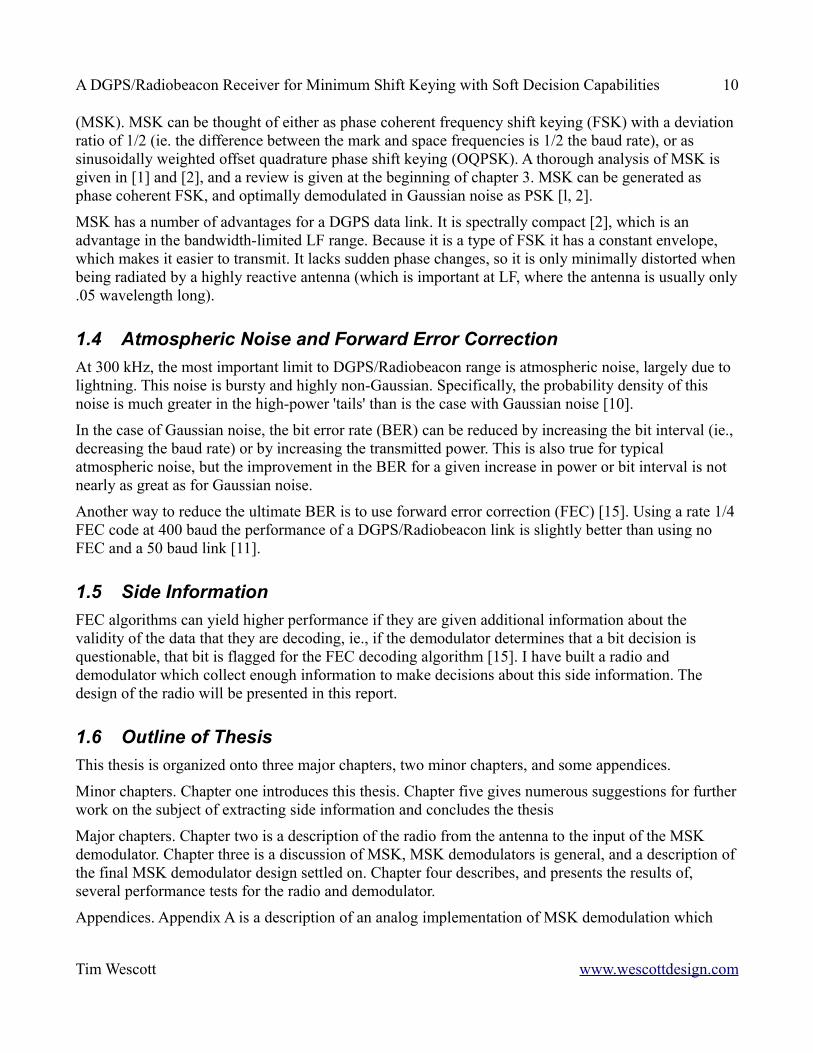
(MSK). MSK can be thought of either as phase coherent frequency shift keying (FSK) with a deviation ratio of 1/2 (ie. the difference between the mark and space frequencies is 1/2 the baud rate), or as sinusoidally weighted offset quadrature phase shift keying (OQPSK). A thorough analysis of MSK is given in [1] and [2], and a review is given at the beginning of chapter 3. MSK can be generated as phase coherent FSK, and optimally demodulated in Gaussian noise as PSK [l, 2].
MSK has a number of advantages for a DGPS data link. It is spectrally compact [2], which is an advantage in the bandwidth-limited LF range. Because it is a type of FSK it has a constant envelope, which makes it easier to transmit. It lacks sudden phase changes, so it is only minimally distorted when being radiated by a highly reactive antenna (which is important at LF, where the antenna is usually only .05 wavelength long).
1.4 Atmospheric Noise and Forward Error CorrectionAt 300 kHz, the most important limit to DGPS/Radiobeacon range is atmospheric noise, largely due to lightning. This noise is bursty and highly non-Gaussian. Specifically, the probability density of this noise is much greater in the high-power 'tails' than is the case with Gaussian noise [10].
In the case of Gaussian noise, the bit error rate (BER) can be reduced by increasing the bit interval (ie., decreasing the baud rate) or by increasing the transmitted power. This is also true for typical atmospheric noise, but the improvement in the BER for a given increase in power or bit interval is not nearly as great as for Gaussian noise.
Another way to reduce the ultimate BER is to use forward error correction (FEC) [15]. Using a rate 1/4 FEC code at 400 baud the performance of a DGPS/Radiobeacon link is slightly better than using no FEC and a 50 baud link [11].
1.5 Side InformationFEC algorithms can yield higher performance if they are given additional information about the validity of the data that they are decoding, ie., if the demodulator determines that a bit decision is questionable, that bit is flagged for the FEC decoding algorithm [15]. I have built a radio and demodulator which collect enough information to make decisions about this side information. The design of the radio will be presented in this report.
1.6 Outline of ThesisThis thesis is organized onto three major chapters, two minor chapters, and some appendices.
Minor chapters. Chapter one introduces this thesis. Chapter five gives numerous suggestions for further work on the subject of extracting side information and concludes the thesis
Major chapters. Chapter two is a description of the radio from the antenna to the input of the MSK demodulator. Chapter three is a discussion of MSK, MSK demodulators is general, and a description of the final MSK demodulator design settled on. Chapter four describes, and presents the results of, several performance tests for the radio and demodulator.
Appendices. Appendix A is a description of an analog implementation of MSK demodulation which
Tim Wescott www.wescottdesign.com
A DGPS/Radiobeacon Receiver for Minimum Shift Keying with Soft Decision Capabilities 11
does not work well in environments where the noise level is high enough to require FEC, but works very well at lower noise levels. Appendix B is a listing of the receiver software in Motorola 68HC11 assembly code.
Tim Wescott www.wescottdesign.com
A DGPS/Radiobeacon Receiver for Minimum Shift Keying with Soft Decision Capabilities 12
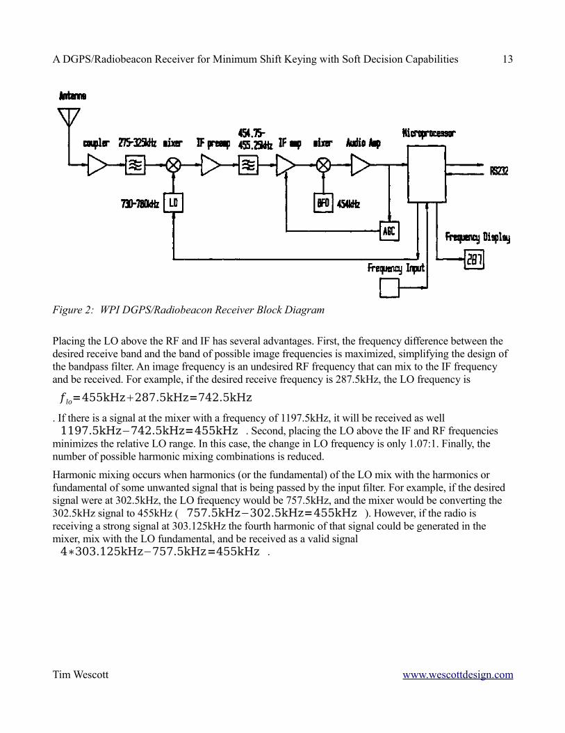
2 The RadioThe basic radio design ahead of the demodulator is a fairly standard double conversion superheterodyne receiver. Figure 3 is a block diagram of the receiver. The antenna is connected to a coupler, which acts as a preamp and an impedance converter, allowing the use of a one-meter whip antenna. The signal from the coupler is fed into the RF filter, which is a five pole Chebychev bandpass filter, designed to pan frequencies in the 275-325 kHz range. The filtered signal is then mixed up to 455 kHz and amplified. This IF signal is filtered by a Collins mechanical filter, which is roughly Gaussian with a 500 Hz bandwidth.
I will start the description of this radio by describing the mixing scheme. Then I will describe the local oscillator (LO). Finally, I will describe the all of the modules along the main signal path: the radio frequency (RF) filter and the mixer, the intermediate (IF) preamp, the IF filter, the IF amplifier, the second mixer and second LO, the audio amplifier and AGC amplifier, and the microprocessor.
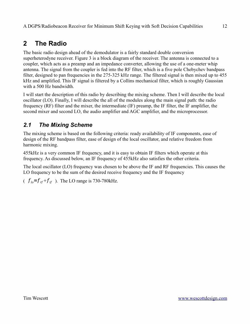
2.1 The Mixing SchemeThe mixing scheme is based on the following criteria: ready availability of IF components, ease of design of the RF bandpass filter, ease of design of the local oscillator, and relative freedom from harmonic mixing.
455kHz is a very common IF frequency, and it is easy to obtain IF filters which operate at this frequency. As discussed below, an IF frequency of 455kHz also satisfies the other criteria.
The local oscillator (LO) frequency was chosen to be above the IF and RF frequencies. This causes the LO frequency to be the sum of the desired receive frequency and the IF frequency
( f lo=f rff if ). The LO range is 730-780kHz.
Tim Wescott www.wescottdesign.com
A DGPS/Radiobeacon Receiver for Minimum Shift Keying with Soft Decision Capabilities 13
Placing the LO above the RF and IF has several advantages. First, the frequency difference between the desired receive band and the band of possible image frequencies is maximized, simplifying the design of the bandpass filter. An image frequency is an undesired RF frequency that can mix to the IF frequency and be received. For example, if the desired receive frequency is 287.5kHz, the LO frequency is
f lo=455kHz287.5kHz=742.5kHz. If there is a signal at the mixer with a frequency of 1197.5kHz, it will be received as well 1197.5kHz−742.5kHz=455kHz . Second, placing the LO above the IF and RF frequencies
minimizes the relative LO range. In this case, the change in LO frequency is only 1.07:1. Finally, the number of possible harmonic mixing combinations is reduced.
Harmonic mixing occurs when harmonics (or the fundamental) of the LO mix with the harmonics or fundamental of some unwanted signal that is being passed by the input filter. For example, if the desired signal were at 302.5kHz, the LO frequency would be 757.5kHz, and the mixer would be converting the 302.5kHz signal to 455kHz ( 757.5kHz−302.5kHz=455kHz ). However, if the radio is receiving a strong signal at 303.125kHz the fourth harmonic of that signal could be generated in the mixer, mix with the LO fundamental, and be received as a valid signal 4∗303.125kHz−757.5kHz=455kHz .
Tim Wescott www.wescottdesign.com
Figure 2: WPI DGPS/Radiobeacon Receiver Block Diagram
A DGPS/Radiobeacon Receiver for Minimum Shift Keying with Soft Decision Capabilities 14
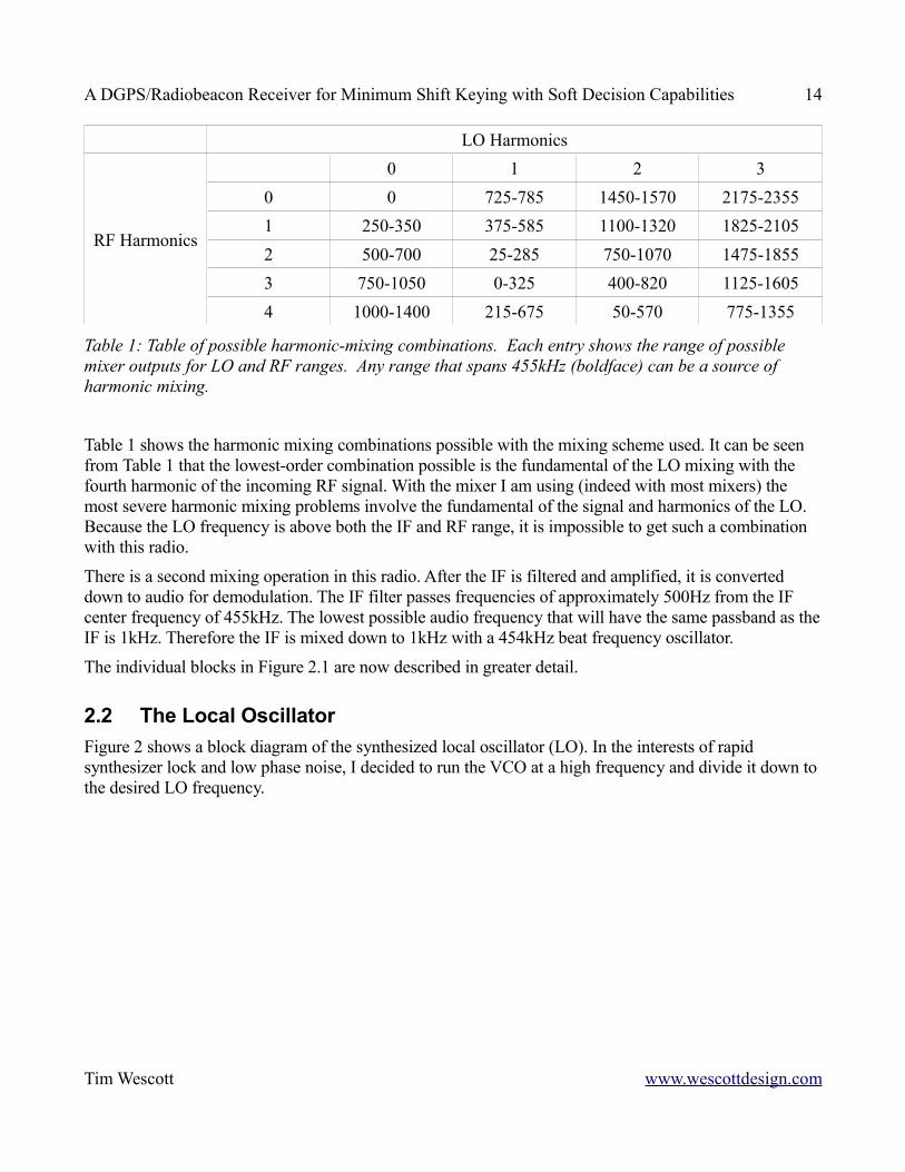
RF Harmonics
LO Harmonics0 1 2 3
0 0 725-785 1450-1570 2175-23551 250-350 375-585 1100-1320 1825-21052 500-700 25-285 750-1070 1475-18553 750-1050 0-325 400-820 1125-16054 1000-1400 215-675 50-570 775-1355
Table 1: Table of possible harmonic-mixing combinations. Each entry shows the range of possible mixer outputs for LO and RF ranges. Any range that spans 455kHz (boldface) can be a source of harmonic mixing.
Table 1 shows the harmonic mixing combinations possible with the mixing scheme used. It can be seen from Table 1 that the lowest-order combination possible is the fundamental of the LO mixing with the fourth harmonic of the incoming RF signal. With the mixer I am using (indeed with most mixers) the most severe harmonic mixing problems involve the fundamental of the signal and harmonics of the LO. Because the LO frequency is above both the IF and RF range, it is impossible to get such a combination with this radio.
There is a second mixing operation in this radio. After the IF is filtered and amplified, it is converted down to audio for demodulation. The IF filter passes frequencies of approximately 500Hz from the IF center frequency of 455kHz. The lowest possible audio frequency that will have the same passband as the IF is 1kHz. Therefore the IF is mixed down to 1kHz with a 454kHz beat frequency oscillator.
The individual blocks in Figure 2.1 are now described in greater detail.
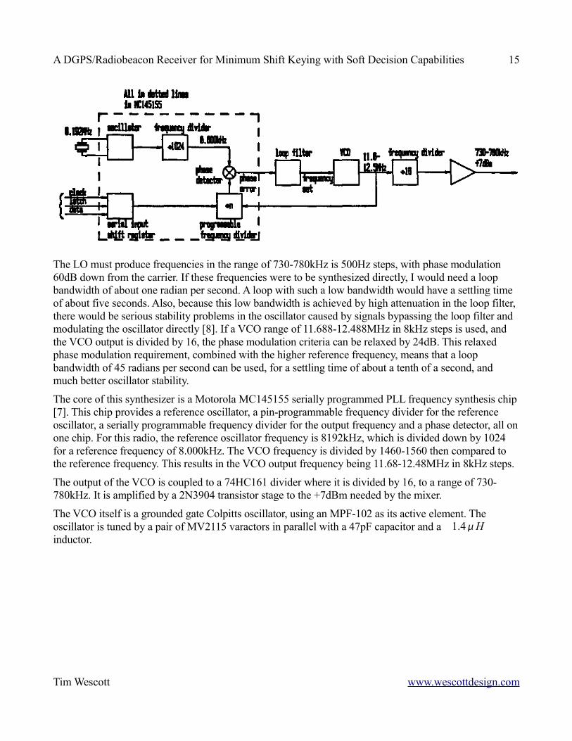
2.2 The Local OscillatorFigure 2 shows a block diagram of the synthesized local oscillator (LO). In the interests of rapid synthesizer lock and low phase noise, I decided to run the VCO at a high frequency and divide it down to the desired LO frequency.
Tim Wescott www.wescottdesign.com
A DGPS/Radiobeacon Receiver for Minimum Shift Keying with Soft Decision Capabilities 15
The LO must produce frequencies in the range of 730-780kHz is 500Hz steps, with phase modulation 60dB down from the carrier. If these frequencies were to be synthesized directly, I would need a loop bandwidth of about one radian per second. A loop with such a low bandwidth would have a settling time of about five seconds. Also, because this low bandwidth is achieved by high attenuation in the loop filter, there would be serious stability problems in the oscillator caused by signals bypassing the loop filter and modulating the oscillator directly [8]. If a VCO range of 11.688-12.488MHz in 8kHz steps is used, and the VCO output is divided by 16, the phase modulation criteria can be relaxed by 24dB. This relaxed phase modulation requirement, combined with the higher reference frequency, means that a loop bandwidth of 45 radians per second can be used, for a settling time of about a tenth of a second, and much better oscillator stability.
The core of this synthesizer is a Motorola MC145155 serially programmed PLL frequency synthesis chip [7]. This chip provides a reference oscillator, a pin-programmable frequency divider for the reference oscillator, a serially programmable frequency divider for the output frequency and a phase detector, all on one chip. For this radio, the reference oscillator frequency is 8192kHz, which is divided down by 1024 for a reference frequency of 8.000kHz. The VCO frequency is divided by 1460-1560 then compared to the reference frequency. This results in the VCO output frequency being 11.68-12.48MHz in 8kHz steps.
The output of the VCO is coupled to a 74HC161 divider where it is divided by 16, to a range of 730-780kHz. It is amplified by a 2N3904 transistor stage to the +7dBm needed by the mixer.
The VCO itself is a grounded gate Colpitts oscillator, using an MPF-102 as its active element. The oscillator is tuned by a pair of MV2115 varactors in parallel with a 47pF capacitor and a 1.4H inductor.
Tim Wescott www.wescottdesign.com
A DGPS/Radiobeacon Receiver for Minimum Shift Keying with Soft Decision Capabilities 16
2.3 Front end CircuitryBecause the ambient atmospheric noise level is quite high at 300 kHz, I paid much more attention in my design to making a radio resistant to overload, rather than making a radio with an incredibly low noise figure. This goal was achieved by minimizing the pre-mixer gain, and using robust designs for the mixer and post-mixer IF preamp.
2.3.1 Antenna CouplerA resonant antenna for this frequency band would be on the order of one quarter of a kilometer long. Such an antenna would be inconvenient, even on a large ship. Standard practice for radios of this type is to use a one meter whip antenna and an active antenna coupler and amplifier that provides an impedance transformation between the whip and the 50 input to the RF filter.
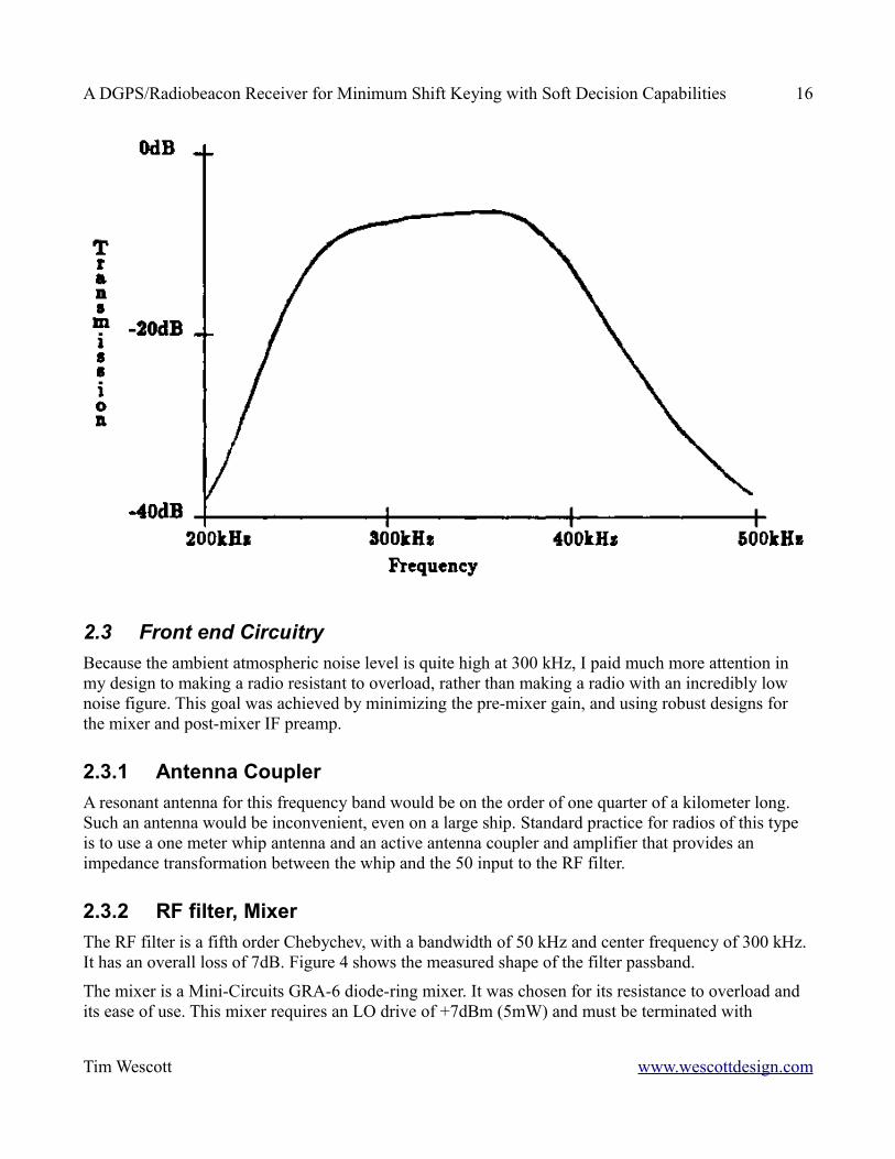
2.3.2 RF filter, MixerThe RF filter is a fifth order Chebychev, with a bandwidth of 50 kHz and center frequency of 300 kHz. It has an overall loss of 7dB. Figure 4 shows the measured shape of the filter passband.
The mixer is a Mini-Circuits GRA-6 diode-ring mixer. It was chosen for its resistance to overload and its ease of use. This mixer requires an LO drive of +7dBm (5mW) and must be terminated with
Tim Wescott www.wescottdesign.com
A DGPS/Radiobeacon Receiver for Minimum Shift Keying with Soft Decision Capabilities 17
50 loads at both the IF and RF ports. If the mixer is driven and terminated properly, it should have a 3rd order intermodulation input intercept of +11dBm1.
2.3.3 IF preampA preamp is inserted between the mixer and the IF filter. This filter solves a variety of problems that would crop up if a passive impedance matching network were attempted. In order to obtain the best mixer performance, the mixer needs to be terminated by a 50 load. The IF filter has an input impedance that varies wildly with frequency around the IF center frequency, and it must be terminated at each end with a 500 resistance in parallel with a 30pF capacitor. Also, the IF filter has about 12dB of attenuation at its center frequency. Furthermore, the match between IF filter and the first IF amplifier was accomplished by a transformer and a ballast resistor, which adds another 2dB of attenuation. Any passive network between the mixer and the IF filter would either have a high amount of loss or would have the same wild impedance variations as the IF filter.
The rated noise figure at the input to the IF amplifier is 6dB [14]. Therefore, the noise figure at the input to the IF filter is about 20dB. In order for the noise figure of the IF preamp to dominate, it had to have a power gain in excess of 20dB. A gain of 24dB was chosen.
The mixer has a 3rd order intermodulation output intercept of +4dBm. Therefore, if the 3rd order intermodulation performance of the radio is to avoid degradation, the IF preamp must have an input intercept that is better than +4dBm. With a gain of 24dB, the output intercept should be +28dBm.
The IF preamp circuit uses heavy feedback both to achieve this intermodulation performance without using too much standing current in the transistor and to provide impedance matching to the mixer and IF filter.
Tim Wescott www.wescottdesign.com
A DGPS/Radiobeacon Receiver for Minimum Shift Keying with Soft Decision Capabilities 18
2.4 IF Filter
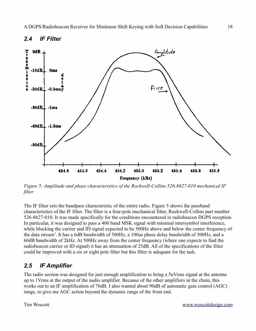
The IF filter sets the bandpass characteristic of the entire radio. Figure 5 shows the passband characteristics of the IF filter. The filter is a four-pole mechanical filter, Rockwell-Collins part number 526-8627-010. It was made specifically for the conditions encountered in radiobeacon DGPS reception. In particular, it was designed to pass a 400 baud MSK signal with minimal intersymbol interference, while blocking the carrier and ID signal expected to be 500Hz above and below the center frequency of the data stream2. It has a 6dB bandwidth of 500Hz, a 100us phase delay bandwidth of 500Hz, and a 60dB bandwidth of 2kHz. At 500Hz away from the center frequency (where one expects to find the radiobeacon carrier or ID signal) it has an attenuation of 25dB. All of the specifications of the filter could be improved with a six or eight pole filter but this filter is adequate for the task.
2.5 IF AmplifierThe radio section was designed for just enough amplification to bring a 5uVrms signal at the antenna up to 1Vrms at the output of the audio amplifier. Because of the other amplifiers in the chain, this works out to an IF amplification of 76dB. I also wanted about 90dB of automatic gain control (AGC) range, to give me AGC action beyond the dynamic range of the front end.
Tim Wescott www.wescottdesign.com
Figure 5: Amplitude and phase characteristics of the Rockwell-Collins 526-8627-010 mechanical IF filter
A DGPS/Radiobeacon Receiver for Minimum Shift Keying with Soft Decision Capabilities 19
The IF amplifier is a pair of Motorola MC1350 IF amplifier ICs. These provide up to 50dB of gain and 56dB of AGC range each. To get maximum gain, I would have had to use transformer or inductive coupling. Since I did not need this much gain, the amplifiers are resistively coupled. In the end, the IF amplifier chain has about 88dB of gain and over 100dB of AGC action.
2.6 2nd Mixer and 2nd Local OscillatorA demodulator which works at audio frequencies is easier to build than one which works at a 455kHz center frequency. Therefore, the 455kHz IF signal is mixed down to a 1kHz center frequency audio signal.
The mixer used is a Signetics NE602 monolithic mixer chip. This chip has input and output impedances of 50 and 1500 , exhibits 18dB of mixer gain, and will provide a 100mV undistorted output. The oscillator in the NE602 is not used. Rather, a CD4060 oscillator/divider and a 7.264MHz crystal are set up to provide a stable 454kHz signal. The output of the CD4060 is attenuated to provide the 200mV p-p signal required by the NE602.
With high IF inputs the NE602 blocks, to the extent that for a large input it can have almost no output at all. This can allow the AGC loop to enter a positive feedback state where increasing IP gain makes the NE602 block and reduce its output, causing the AGC circuit to increase the IF gain, etc. To work around this problem, a pair of diodes were put in parallel across the IF inputs to the mixer, which limits the input amplitude to .6Vp-p. With the input to the mixer limited in this manner, it always has a high enough output to actuate the AGC circuit.
2.7 Audio Amplifier and AGC AmplifierThe audio amplifier is a straightforward differential amplifier that provides a voltage gain of 20dB. 10nF capacitors are used to filter out the high frequency components of the mixer output.
The AGC is designed to keep the signal to the demodulator fairly constant while being insensitive to the large amplitude small duration excursions in the signal envelope that result from lightning noise. The audio peaks are rectified, and the resulting DC is integrated to derive the AGC. The AGC is designed for a time constant of about 200ms.
2.8 MicroprocessorThe radio is entirely microprocessor controlled. This makes it easy to interface a panel control, digital display, and frequency synthesized LO. Microprocessor control also allows for easy modification to the operation of the radio.
2.8.1 The MC68HC11The Motorola MC68HC11 microcontroller was chosen as the radio CPU for a variety of reasons. It has all the features one would expect in a microcontroller, including the ability to use onboard program ROM, onboard RAM, and comprehensive I/O capabilities. More importantly, it has hardware multiply, various timers that can be configured as timed interrupts or as individual vectored hardware interrupts, and an on board sample and hold A/D converter with four or eight inputs.
Tim Wescott www.wescottdesign.com
A DGPS/Radiobeacon Receiver for Minimum Shift Keying with Soft Decision Capabilities 20
As we shall see in later chapters, this processor is fine for my original concept, but it is barely fast enough to run an all software demodulator.
Tim Wescott www.wescottdesign.com
A DGPS/Radiobeacon Receiver for Minimum Shift Keying with Soft Decision Capabilities 21
3 The DemodulatorsTwo different demodulators were built for this radio. One uses the microcontroller to sample the MSK at audio, and has the entire demodulator implemented in software. It was designed for very high frequency stability. Its design will be discussed in this chapter. The other is a purely analog design. It runs at a center frequency of 1kHz, and uses CD4046 phase lock loop ICs as its basic frequency reference element. It works well for low to medium noise levels, but cannot maintain lock for high noise levels. Because the analog design does perform well at bit error rates below 10-3 it is sufficient for non FEC use, so its design is presented in Appendix A.
This chapter is organized as follows. Section 3.1 is an overview of MSK. Once MSK has been explained, a theoretical model for a MSK demodulator is presented. Thus, section 3.2 covers the theoretical model for a MSK detector, assuming that the proper synchronization signals are available, and Section 3.3 covers the theoretical model for the synchronization signal recovery. After the theoretical model is presented (and the reader has an idea of how a MSK demodulator is supposed to work), a microprocessor based demodulator design is presented. Section 3.4 presents the operations performed by the microprocessor based synchronization recovery algorithm and goes in depth into the design of the phase-locked loops in the synchronization recovery algorithm. Finally, section 3.5 presents the operations performed by the microprocessor based detector algorithm.
Tim Wescott www.wescottdesign.com
A DGPS/Radiobeacon Receiver for Minimum Shift Keying with Soft Decision Capabilities 22
1.7 MSK
Tim Wescott www.wescottdesign.com
A DGPS/Radiobeacon Receiver for Minimum Shift Keying with Soft Decision Capabilities 23
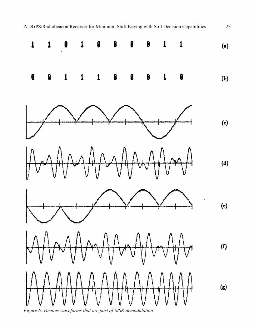
Tim Wescott www.wescottdesign.comFigure 6: Various waveforms that are part of MSK demodulation
A DGPS/Radiobeacon Receiver for Minimum Shift Keying with Soft Decision Capabilities 24
This radio is designed to receive MSK signals. In designing an optimum demodulator for MSK it is best to think of MSK as offset quadrature PSK (OQPSK) with sinusoidal pulse weighting [2]. If ai t and aq t are the bits transmitted by the inphase and quadrature components of the
OQPSK signal, then an MSK signal would be equal to
a t = at tcost /2Tbcos2 ft
aqt sint /2Tbsin2 ft(1)
where T b is one bit interval. Figure 11 shows the ai t , aq t and the various components of the MSK signal defined by (3.1). Figure 11(a) shows an example bit stream to be sent.
Like all types of phase modulation, MSK suffers from phase ambiguity at the demodulator. The cure for this is to use differentially encode the bitstream to be sent. Figure 11(b) shows the bitstream of Figure11(a) after it has been differentially encoded.
This encoded bitstream must be broken up into two parts before being sent over the inphase and quadrature channels. Figure 11(c) shows the inphase multiplier waveform, with the corresponding multiplier values shown as ±1 inside the waveform. This encoded waveform is shown multiplied by the inphase carrier to yield the inphase signal in Figure 11(d) [Figure 11(d) is the first term in (3.1)]. Similarly, the sinusoidally shaped quadrature multiplier and the quadrature signal are shown in Figure11(e) and Figure 11(f). The composite signal, as given by (3.1) is shown in Figure 11(g).
Using a trigonometric identity, (3.1) can be rewritten as
at = cos[2ftbkt t /2Tbk] (2)where bkt =−at t aq t and kt = at t 1/2 . Figure 11 and equation (3.2) show that MSK is an FSK signal with signaling frequencies fm = f1 /4Tb and f a= f−1/4Tb . In addition, a one in our original bitstream corresponds to a high frequency (mark) tone, and a zero in the original bitstream corresponds to a low frequency (space) tone. Indeed (as shall be described later) if one has an easy method to produce phase-coherent FSK with the proper deviation ratio, it is simple indeed to produce MSK.
Tim Wescott www.wescottdesign.com
A DGPS/Radiobeacon Receiver for Minimum Shift Keying with Soft Decision Capabilities 25
3.1.1 MSK Detection
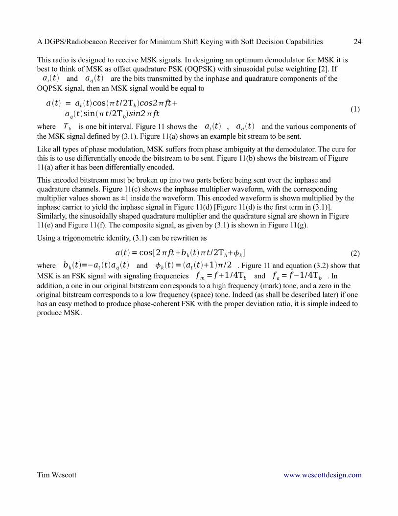
If one treats MSK as OQPSK it is easy to demodulate. Figure 7 shows a typical MSK demodulator [2]. The incoming signal is multiplied by the inphase and quadrature signals
z t = 2cos t /2Tbcos2ftand
y t =2sin t /2Tbsin2ft(the multiplication by two will become clear later) followed by integrate and dump circuits. This multiply-integrate operation constitutes correlation detection or matched filtering, which is an optimum detection operation for a signal in white Gaussian noise with no intersymbol interference.
Note that this detector is not an optimum detector for non-Gaussian noise. However, interference from the radiobeacon carrier and identification signal (which occurs at approximately ±500 Hz) makes wideband signal processing of a 400 baud signal virtually impossible. This detector is near optimum for the signal conditions encountered. If a lower baud rate were to be used with this radio, other, more nearly optimum (wide band) detection schemes for non-Gaussian noise should be investigated (10). These schemes would include hard limiters, clippers, blankers, or some other sort of zero memory non-linearity to suppress the impulse noise.
Tim Wescott www.wescottdesign.com
Figure 7: Basic MSK Correlation Detector. This part of the MSK demodulator implements the multiply and integrate-and-dump functions
A DGPS/Radiobeacon Receiver for Minimum Shift Keying with Soft Decision Capabilities 26
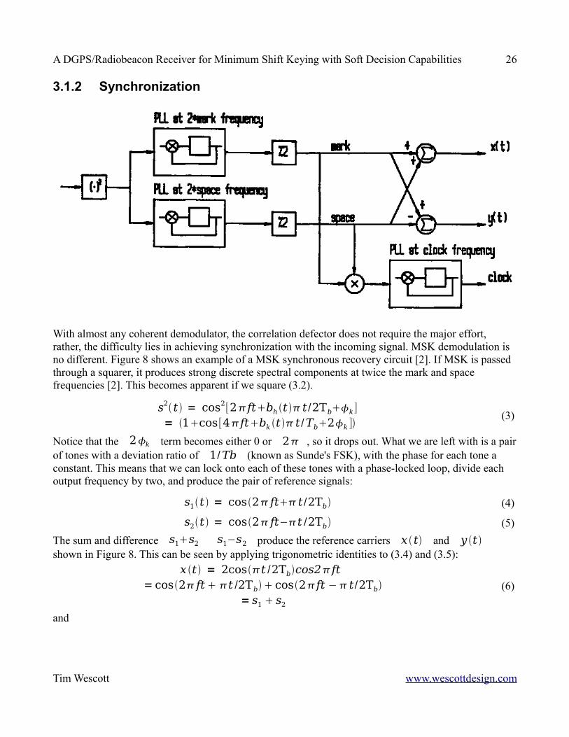
3.1.2 Synchronization
With almost any coherent demodulator, the correlation defector does not require the major effort, rather, the difficulty lies in achieving synchronization with the incoming signal. MSK demodulation is no different. Figure 8 shows an example of a MSK synchronous recovery circuit [2]. If MSK is passed through a squarer, it produces strong discrete spectral components at twice the mark and space frequencies [2]. This becomes apparent if we square (3.2).
s2 t = cos2[2ftbh t t /2Tbk]= 1cos[4ftbk t t /Tb2k ]
(3)
Notice that the 2k term becomes either 0 or 2 , so it drops out. What we are left with is a pair of tones with a deviation ratio of 1/Tb (known as Sunde's FSK), with the phase for each tone a constant. This means that we can lock onto each of these tones with a phase-locked loop, divide each output frequency by two, and produce the pair of reference signals:
s1 t = cos2 ft t /2Tb (4)
s2 t = cos2 ft−t /2Tb (5)The sum and difference s1s2 s1−s2 produce the reference carriers x t and y t shown in Figure 8. This can be seen by applying trigonometric identities to (3.4) and (3.5):
x t = 2cost /2Tbcos2ft
= cos2 ft t /2Tb cos2ft − t /2Tb= s1 s2
(6)
and
Tim Wescott www.wescottdesign.com

A DGPS/Radiobeacon Receiver for Minimum Shift Keying with Soft Decision Capabilities 27
y t = 2sin t /2Tbsin2 ft= cos2 ft t /2Tb − cos2ft − t /2Tb
= s1 − s2 (7)
For a clock reference, s1 and s2 can be multiplied: s1 t s2t = cos2ft t /2Tbcos2 ft− t /2Tb
= cos4 ft cos t /Tb/2 (8)
When this signal is locked onto with a phase-locked loop designed to run at a frequency of 1/2Tb , the output will be proportional to sin t /Tb which is the desired timing waveform.
3.2 Microprocessor based demodulatorThe discrete-time microprocessor based demodulator offers numerous advantages over the continuous-time demodulator. Many of the shortcomings of the continuous-time demodulator could be overcome by careful design and more expensive components, but using a microprocessor based demodulator cures these shortcomings while adding tremendous versatility.
This demodulator is a fairly faithful rendering of the functions delivered by the basic demodulator given in [2] and described at the beginning of this chapter. The block diagrams that describe this demodulator are largely rearrangements of the block diagrams at the start of this chapter (Figure 7 and Figure 8 — basic carrier recovery and basic coherent detector).
A complete listing of the receiver software, including the demodulator routine, is contained in Appendix B.
Frequency stability was the original motivation for going to a microprocessor based demodulator. The low frequency stability available from the CD4046 phase-locked loop chips required such high loop bandwidths that the loops could not maintain lock in the presence of high levels of noise. A crystal based frequency generation scheme would provide the necessary frequency stability. Since a microprocessor based approach offers versatility as well as frequency stability, that approach was chosen. The microprocessor samples data at intervals which are determined by the on board timer. The timer interval is derived from the crystal controlled microprocessor clock, which gives us the required crystal frequency stability.
The demodulator algorithm is implemented as an interrupt routine in the MC68HC11 microcontroller. The routine is called 15 times per bit interval (once every 166.5 s , about six times the audio center frequency) under the control of an output timer on board the microcontroller. It reads the last A/D conversion value, then starts a new conversion.
3.3 The Timing Recovery AlgorithmSince the main motivation for this demodulator was phase stability, I will start my description of the demodulator by describing the phase and bit timing recovery phase-locked loops.
Tim Wescott www.wescottdesign.com
A DGPS/Radiobeacon Receiver for Minimum Shift Keying with Soft Decision Capabilities 28
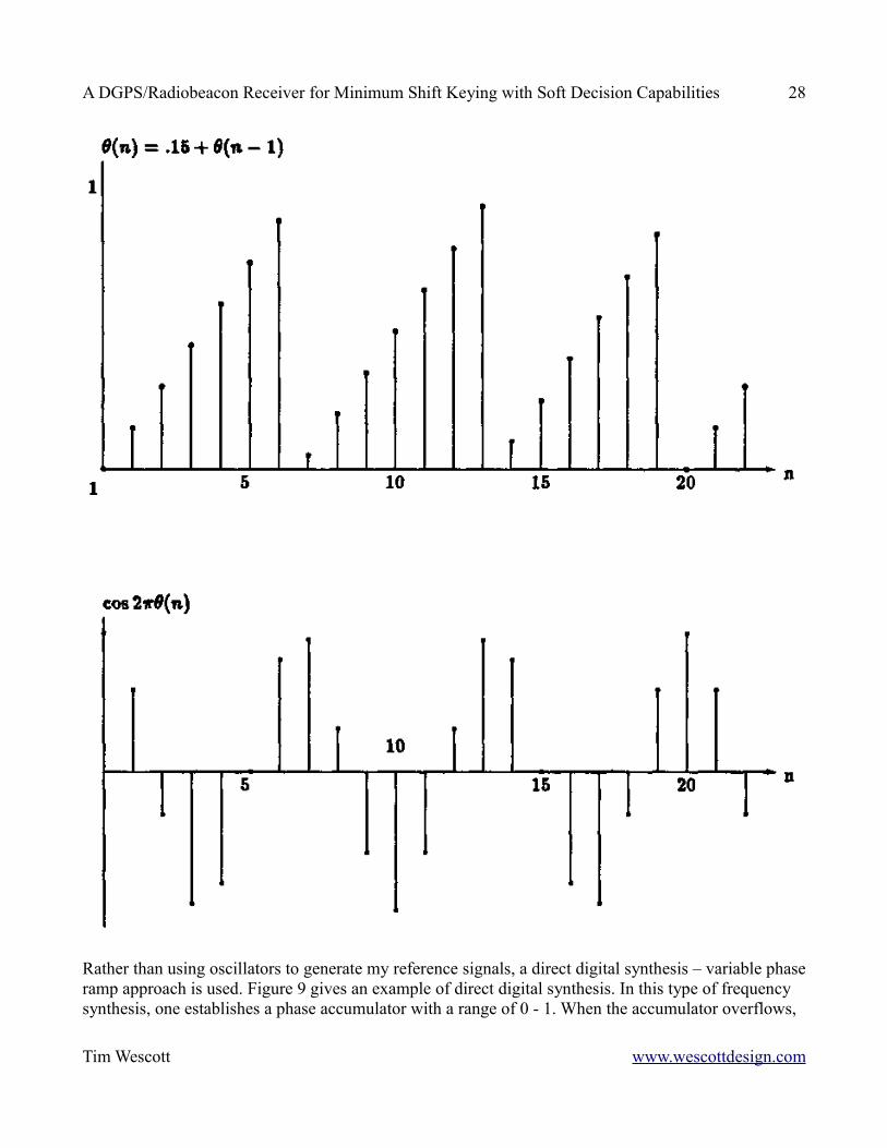
Rather than using oscillators to generate my reference signals, a direct digital synthesis – variable phase ramp approach is used. Figure 9 gives an example of direct digital synthesis. In this type of frequency synthesis, one establishes a phase accumulator with a range of 0 - 1. When the accumulator overflows,
Tim Wescott www.wescottdesign.com
A DGPS/Radiobeacon Receiver for Minimum Shift Keying with Soft Decision Capabilities 29
the phase value just wraps around. If one wants a sinusoidal waveform from the synthesizer, one takes the phase ramp from the accumulator and calculates the sine of the phase.
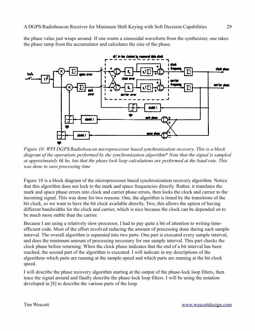
Figure 10 is a block diagram of the microprocessor based synchronization recovery algorithm. Notice that this algorithm does not lock to the mark and space frequencies directly. Rather, it translates the mark and space phase errors into clock and carrier phase errors, then locks the clock and carrier to the incoming signal. This was done for two reasons: One, the algorithm is timed by the transitions of the bit clock, so we want to have the bit clock available directly. Two, this allows the option of having different bandwidths for the clock and carrier, which is nice because the clock can be depended on to be much more stable than the carrier.
Because I am using a relatively slow processor, I had to pay quite a bit of attention to writing time-efficient code. Most of the effort involved reducing the amount of processing done during each sample interval. The overall algorithm is separated into two parts. One part is executed every sample interval, and does the minimum amount of processing necessary for one sample interval. This part checks the clock phase before returning. When the clock phase indicates that the end of a bit interval has been reached, the second part of the algorithm is executed. I will indicate in my descriptions of the algorithms which parts are running at the sample speed and which parts are running at the bit clock speed.
I will describe the phase recovery algorithm starting at the output of the phase-lock loop filters, then trace the signal around and finally describe the phase-lock loop filters. I will be using the notation developed in [8] to describe the various parts of the loop.
Tim Wescott www.wescottdesign.com
Figure 10: WPI DGPS/Radiobeacon microprocessor based synchronization recovery. This is a block diagram of the operations performed by the synchronization algorithm* Note that the signal is sampled at approximately 6k he, but that the phase lock loop calculations are performed at the baud rate. This was done to save processing time
A DGPS/Radiobeacon Receiver for Minimum Shift Keying with Soft Decision Capabilities 30
3.3.1 Phase error estimationAt each sample interval, the clock summer adds the clock increment (proportional to the clock frequency) to the clock phase. Since the clock frequency is approximately 100Hz (one quarter of the bit rate), and the sample interval is 166.5 s , this increment is
f cl= Ts100Hz = 166.5s100Hz = .01665where Ts= 166.5s is the sample interval. The carrier summer works the same, except the increment
f ca = 1000Hz166.5s = .1165The clock and carrier phase become:
clm = [cl m − 1 f clm]mod 1 (9)
cam = [cam− 1 f cam ] mod 1 (10)The mark and space frequencies are symmetrical about the carrier frequency and differ by one half the baud rate. Since the clock frequency is one quarter the bit rate, the mark and space phase can be derived from the clock and earner phase:
mm = [cam cl m] mod 1 (11)
sm = [ca m − cl m ] mod 1 (12)The incoming signal is sampled at approximately 6kHz. For timing recovery, this signal is then squared. The mark error is calculated by multiplying the squared signal by a square wave at twice the mark frequency and the result added to a variable for the mark error. The space error is calculated the same way using a square wave at twice the space frequency. Overall, the summer between the phase detector and the loop filters has an effect on noise and stability similar to that of a low pass filter in a continuous-time phase locked loop. As long as the bandwidth of the phase recovery loops are kept fairly low (which is what we want to do anyway) the effect of this summation step on loop stability can be neglected.In order to execute this multiply and add operation in the minimum of processor time the processor checks the phase, and if it is in the interval [1/4, 1/2) or the interval [3/4, 1) (ie. if the second most significant bit is one) the signal is subtracted from the error variable, otherwise the signal is added to the error variable. This has the effect of a square wave multiply and add, but is much faster for this processor than using the multiply instruction. Ideally, the processor would look up the sine of that phase and do a full multiply and add, but this processor is not fast enough.
3.3.2 The gain blocksAt the end of a bit interval, when the algorithm has collected phase error information, the algorithm goes into the phase-locked loop filter calculations. The clock phase error is calculated from the difference of the mark and space phase errors (the carrier error is calculated from the sum). Because the clock and carrier loops are identical except for the center frequencies and loop bandwidths, I will only describe the clock loop filters. However, I will note any differences between the clock and carrier loops.
Tim Wescott www.wescottdesign.com
A DGPS/Radiobeacon Receiver for Minimum Shift Keying with Soft Decision Capabilities 31
If we look at the squarer-multiplier-summer combination as a phase detector, we can calculate the phase detector gain. The peak-peak voltage of the signal present at the input of the A/D converter is 1Vp-p, and its DC average is 2.5V. Eq. (3.2) can be modified to show the signal received at the A/D converter;
r t = .5V cos[2 ftbh t t /2Tb h ] 2.5V ,= .5V cosr t 2.5V (13)
where rt = 2 ft bk t t /2Tb k . In discrete time, rdm = .5V cosrmTs where the variable m represents one sample interval.
This rd gets sampled and converted by the microprocessor, and turned into a 2's complement fraction;
r m = .1cosr mTs (14)This input signal gets squared, to yield the synchronization signal
r2m = .01cos2rmTs ¿= .011cos[4fmTs bh t mTs/tb 2h]
(15)
The mark and space references can be obtained by locking onto this signal with a pair of phase-locked loops at twice the mark and space frequencies, as is done in the theoretical model. Alternately, the loops can be made to lock onto the clock and carrier phases and the mark and space phases can be calculated from them. This algorithm follows the latter approach.
If we have estimates of the mark and space phase errors we can compute the clock and carrier errors. We define the mark and space errors at the start of a bit interval as smn and esn , respectively (note the use of n as opposed to m to denote that the interval is a bit interval rather than a sample interval). The clock phase is one half the difference between the mark and space phases, while the carrier phase is one half the sum of the mark and space phases. In other words,
ecln = [emn − esn]/2 (16)(clock phase error)
ecan = [emn − es n ] /2 (17)(carrier phase error).
The synchronization signal in (3.15) can be used to get estimates of the mark and space phase errors at every bit interval. In the case of the mark phase, the synchronization signal is multiplied by the sine of twice the mark phase:
Em m=r2msin4m m=.005[1os2rm ]sin4m m
=.005[sin4m mcos2rmsin4m m] (18)
Tim Wescott www.wescottdesign.com
A DGPS/Radiobeacon Receiver for Minimum Shift Keying with Soft Decision Capabilities 32
This signal has components at either the clock frequency or approximately DC, twice the mark frequency, and at approximately four times the mark frequency. Because the phase locked loops are essentially low pass filters, and because the loop filters are preceded by the summation operation, we can ignore all but the DC component. If a mark is transmitted, we can assume that rm − 2m m remains constant over the bit interval such that
rm − 2m m = em nand there will be a DC component to em m :
em m = .0025sin2 [em n]. If a space is transmitted, there will be no DC component, and we can say that
em m = 0The error signal em m is summed over one bit period (15 samples). After this summation, we can assume that all of the AC components of em m have been filtered out, leaving only
edm n = ∑m= 15n
15n 1em m
(because of the low-pass nature of phase-lock loops, any AC that gets passed at this stage will be filtered out later). Note that at the end of a bit period, edm n has one of two different expected values depending on the bit that was transmitted. If we assume that there is equal probability of a mark or a space being sent, the overall expected value is
E {edm n } = .5E {edmn ∣mark transmitted } .5E {edm n∣spacetransmitted }= .515.0025sin 2 [emn ] 0
= .01875sin 2[emn]The forgoing analysis would be identical for the space error, so I won't repeat it here, other than to note that I will use eds n for my space error variable.
In this algorithm, these mark and space error variables are used to obtain clock and carrier error variables. These are calculated as
ecl n = edmn − edsnfor the clock error, and
eca n = edm n eds nfor the carrier error.
If we make the approximation that the sine of a small angle is equal to that angle in radians, then we can find the expected value of the dock error estimate for small mark and space phase errors.
E {eel n } = E {edm n−edsn }= .1875em n − esn
= .0375ecln
Tim Wescott www.wescottdesign.com
A DGPS/Radiobeacon Receiver for Minimum Shift Keying with Soft Decision Capabilities 33
Therefore, the phase detector gain is
Kd =E {ecl n}ecln
= .0375rad−1
The foregoing analysis of the clock loop phase detector gain is exactly the same as the analysis of the carrier loop detector gain. Hence, in my analysis of the carrier loop, I will use eq. (3.23) as the expression for phase detector gain.
The gain of the frequency to phase summer is simply the number of samples per bit times the bit rate;
Ko= 15400Hz = 6000HzThe other two blocks that contribute phase gain around the loop are the khl block, which is the block that the designer can adjust to control the loop bandwidth, and the sin 4 block. The sin 4 block contributes a gain of 4rad /cycle .
3.3.3 Loop Filter Calculations and BandwidthIn a phase locked loop the bandwidth is equal to the gain around the loop, so the bandwidth for this loop is
Kcl = 4KdKhlKo
= 4 rad /cycle.0375rad−16000Hz Khl= 2827 rad /secK hl
. If, for example, Khl = 2−10 ,
Kcl = 2−102827rad /sec= 276rad /sec
For stability the loop filter requires a zero at w2Kcl /8 . In this case, we need w2.35rad /sec [8]. With w2=.39rad /sec ,
w2Tb=.00098=2−10
We can find the RMS phase error for this loop if we know some details about the input noise. For a phase-locked loop with a squarer at the input, the phase error at the output of the loop is related to the loop bandwidth ( BL ), input filter noise bandwidth ( Bi ), and input signal to noise ratio( SNR i ) [8]. If we assume Gaussian noise, this RMS phase error is
c= BL
BiSNR i1 12SNR i
. If we assume that FEC will allow valid data reception at a BER rate of .01 out of the demodulator, then we must have phase lock loops that can perform at this noise Level. The theoretical signal to noise level that would cause a .01 BER with the IF filter in this radio is 4.6dB, and the IF filter noise bandwidth is 490Hz. Therefore, the RMS phase error at the output of the loop with a bandwidth of
Tim Wescott www.wescottdesign.com
A DGPS/Radiobeacon Receiver for Minimum Shift Keying with Soft Decision Capabilities 34
2.76rad/sec would be
a = .44Hz490Hz2.9 1 1
5.8which is more than acceptable.
The carrier phase recovery loop is exactly the same as the clock phase recovery loop, with the exception that the center frequency is 1000Hz rather than 100Hz, and the value of the Kel multiplier may be higher, for a higher loop bandwidth. In practice, it seems that values of Khl=2−10 to 2−6 and Kha=2−6 work best (see chapter 4 for test results).
3.3.4 Limit CyclesThe output of the phase detector in this algorithm is a 16 bit fractional number (the value ranges from -.5 to .5, with the smallest possible increment = 2−16 ). In a digital control system such as this, one must pay attention to the possibility of limit cycles. A limit cycle is a low-level oscillation in a digital control system caused by the finite resolution of the state variables [13, pp345-353]. To avoid limit cycles of magnitude greater than .088 radians (5 degrees), there must be enough bits of precision at the output of the Khl multiplier so that at least its lowest order bit is affected by a .088rad error at the phase detector. Similarly, there must be enough bits of precision at the output of the w2T multiplier so that its lowest bit is affected by a .088rad error at the phase detector. For a .088rad error the output of the phase detector will be:
ecl=.0375rad−1.088r=.00332−6
For Kch=2−10 , the output is less that what can be represented in two bytes;
.00332−102−14
The next larger convenient site for the output of the Khl multiplier is three bytes, which is more than enough precision for our limit cycle criterion. The output of the w2T summer is around 2−10 smaller than the output of the Khl multiplier, so the w2T summer must have one more byte of precision for a total of four bytes.
Overall, the amount of precision provided is enough for keep the limit cycle amplitude below 4 milliradians, which should be below the expected RMS noise at the output of the loops in all but the quietest of conditions.
The instantaneous frequency is determined by the sum of the outputs of the Kcl and w2T summers in Figure 10. In practice, this instantaneous frequency is calculated then stored. The word size chosen for this is three bytes, to match the Kcl summer. Using this size, rather than four bytes, ignores the final byte of the w2T summer, but I feel it will not introduce any more limit cycle problems.
Tim Wescott www.wescottdesign.com

A DGPS/Radiobeacon Receiver for Minimum Shift Keying with Soft Decision Capabilities 35
3.3.5 Lock AcquisitionPhase lock loops have a linear phase detector characteristic is highly non-linear, and the analysis is very involved, so rather than going into it here the reader is referred to [3] and [8]. One result is presented here however. For our carrier loop, if our initial frequency error is w ea and the input noise is negligible, the lock time will be
T pa=wea /K ca
2−1w2
From this we see that the lock time is proportional to the square of the frequency error over the loop bandwidth. Therefore if we want fast lockup and small loop bandwidth, it is important to make sure that the initial frequencies of the clock and carrier loops will be close to their final values. Also, it is a good idea to insure that if the radio receives only noise inputs for a prolonged period of tine the loop frequencies do not wander too far away from the correct values.
Three things have been done to deal with these frequency uncertainty problems. One, when the radio is turned on, the microprocessor initializes the loop frequencies to their nominal values (100Hz for the clock loop, 1000Hz for the carrier loop). Two, after every iteration of the w2T summers (one for the carrier, one for the clock) the frequency value is checked against frequency limits ( 1000±10Hz for the carrier, one for the carrier, 100±.5 Hz for the clock).and if these limits are exceeded, the frequency is set to just inside the limit. Finally, the bandwidth of the carrier loop is larger than the bandwidth of the clock loop.
3.3.6 Carrier Stability and Carrier l\Loop BandwidthI mentioned in th last section that the carrier frequency is much less certain than the clock frequency. In this section I will give a rough analysis of why this is, and I will demonstrate the effects of changing the loop bandwidth on carrier reference stability and loop acquisition time.
I will assume that the DGPS/Radiobeacon clock and carrier frequencies are derived by frequency division (or synthesis) from a single crystal controlled source. Therefore, both the clock and carrier frequencies of the transmitted signal can be depended on the be accurate to at least ±10ppm .
There are some frequency references in the receiver that affect the carrier as well: one, the clock frequency reference at the receiver is synthesized from a single crystal controlled source (the microprocessor crystal), two, the receiver carrier frequency reference is affected by the difference between the LO frequency and the BFO (second LO) frequency, which are crystal controlled by two different crystals. Three, the carrier frequency is also affected by the sampling rate of the microprocessor, which is derived by dividing down the microprocessor clock.
We can assume that the initial frequencies of all of the crystal controlled sources in the receiver are adjusted to ±1ppm to start (this is a calibration which can be carried out by the microprocessor at the time the radio is manufactured). We can also assume that the crystal frequency never varies more than ±10ppm with temperature and that the relative crystal error will approximately track with temperature variations.
Ultimately, the clock frequency only depends on the crystal source at the transmitter and the crystal
Tim Wescott www.wescottdesign.com
A DGPS/Radiobeacon Receiver for Minimum Shift Keying with Soft Decision Capabilities 36
source at the receiver. Since both of these sources are accurate to ±10ppm , the worst that we can expect of the clock is that it will be 200Hz±20ppm (remember that the clock loop reference is one half the bit rate). It follows that the maximum clock frequency variation at the demodulator will be:
e fcl = 200hz 1∗10−3200Hz1∗10−3= 42.5rad / sec
. This is small enough to be ignored.
The carrier frequency can vary much more. If we assume that the transmitter is accurate to ±10ppm, and that the LO and BFO frequencies track, the carrier frequency variation at the demodulator will be:
e fca = 780kHz−454kHz1∗10−5350kHz1∗10−5= 6.76Hz
= 42.5rad / secUnlike the possible dock frequency error, this error is quite significant. If we wanted the carrier loop to be able to acquire this frequency instantly, we would need a bandwidth larger than 42.5rad/sec. For a loop bandwidth of exactly 42.5rad/sec and a theoretical BER of .01, the rms phase noise in the loop output isc = sqrtfrac6.76 490Hz 2.91 frac15.8
= .074 rad
which is rather high. To reduce this phase noise, we must reduce the bandwidth of the loop, thereby increasing the acquisition time.
If we use a K la of 2−8 then the carrier loop bandwidth is K ca = 11.0rad / sec . Using equation (3.27), this gives us an acquisition time of
T pa =
was
K ca2
−1
w2
=42.5rad / sec11.0rad /sec
2
−1
.39 rad /sec= 36sec
if we leave the loop zero at w2 = .39 rad / sec . As a worst case, this acquisition time is bearable, although it could be better. In practice, at room temperature the demodulator attains lock immediately with K ca=11.0rad /sec .
Chapter 4 has some test results for the effect various values of the carrier loop bandwidth have on the error rate performance of the demodulator.
Tim Wescott www.wescottdesign.com
A DGPS/Radiobeacon Receiver for Minimum Shift Keying with Soft Decision Capabilities 37
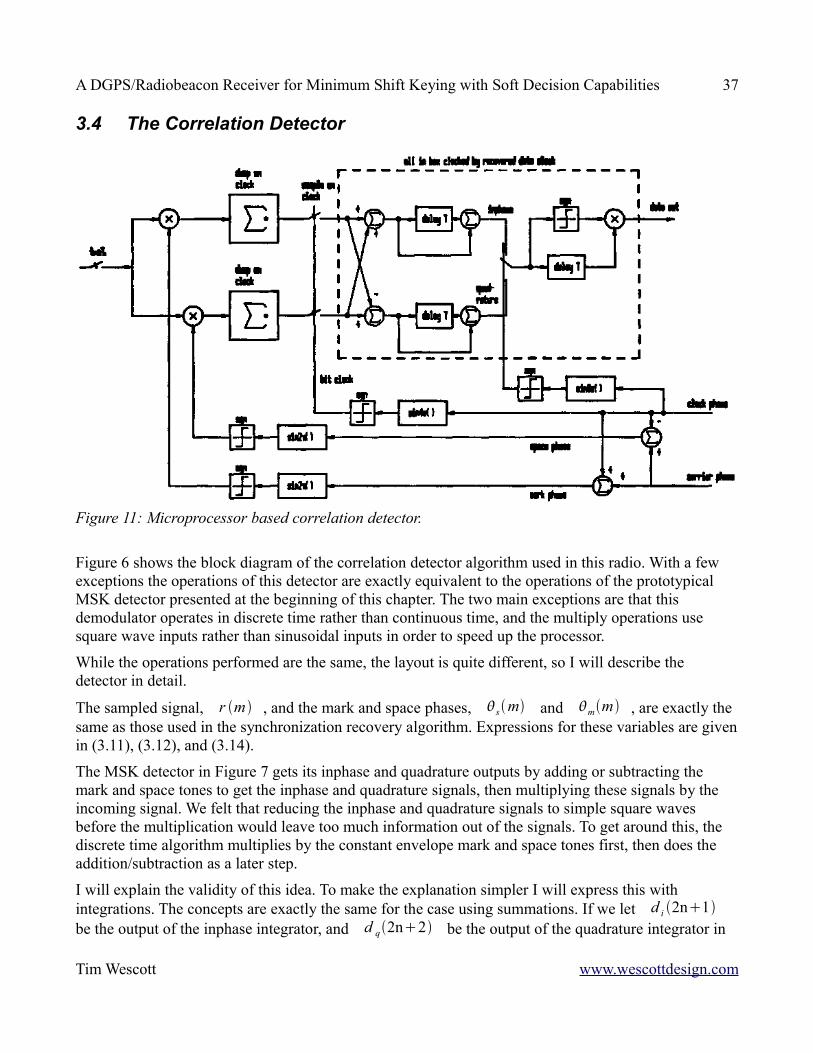
3.4 The Correlation Detector
Figure 6 shows the block diagram of the correlation detector algorithm used in this radio. With a few exceptions the operations of this detector are exactly equivalent to the operations of the prototypical MSK detector presented at the beginning of this chapter. The two main exceptions are that this demodulator operates in discrete time rather than continuous time, and the multiply operations use square wave inputs rather than sinusoidal inputs in order to speed up the processor.
While the operations performed are the same, the layout is quite different, so I will describe the detector in detail.
The sampled signal, r m , and the mark and space phases, sm and mm , are exactly the same as those used in the synchronization recovery algorithm. Expressions for these variables are given in (3.11), (3.12), and (3.14).
The MSK detector in Figure 7 gets its inphase and quadrature outputs by adding or subtracting the mark and space tones to get the inphase and quadrature signals, then multiplying these signals by the incoming signal. We felt that reducing the inphase and quadrature signals to simple square waves before the multiplication would leave too much information out of the signals. To get around this, the discrete time algorithm multiplies by the constant envelope mark and space tones first, then does the addition/subtraction as a later step.
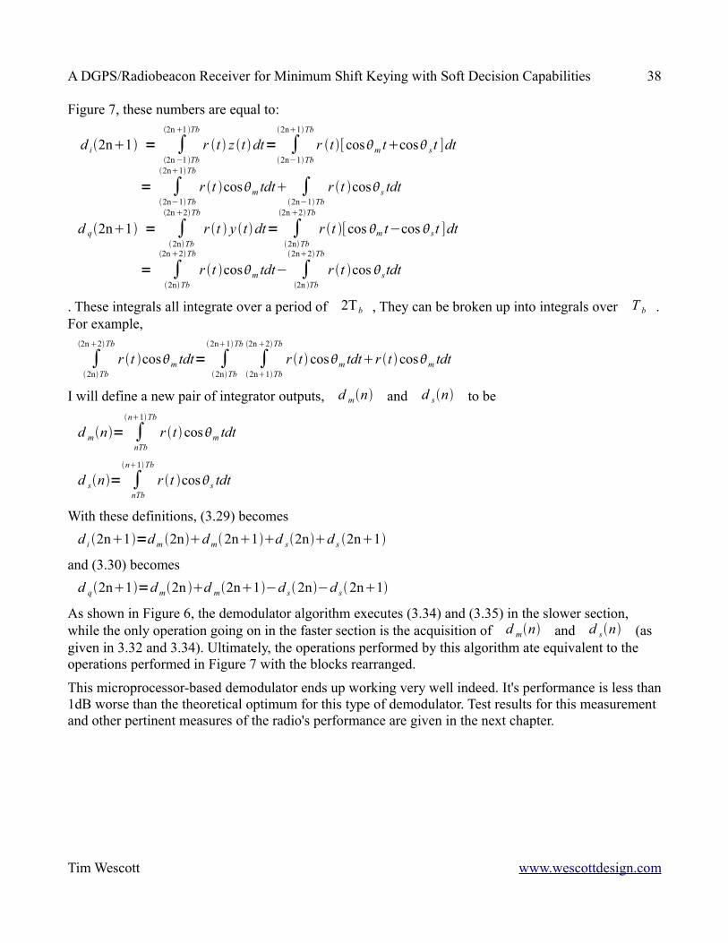
I will explain the validity of this idea. To make the explanation simpler I will express this with integrations. The concepts are exactly the same for the case using summations. If we let d i 2n1 be the output of the inphase integrator, and d q2n2 be the output of the quadrature integrator in
Tim Wescott www.wescottdesign.com
Figure 11: Microprocessor based correlation detector.
A DGPS/Radiobeacon Receiver for Minimum Shift Keying with Soft Decision Capabilities 38
Figure 7, these numbers are equal to:
d i2n1 = ∫2n−1 Tb
2n1 Tb
r t z t dt= ∫2n−1Tb
2n1Tb
r t [cosm tcos s t ]dt
= ∫2n−1Tb
2n1Tb
r t cosm tdt ∫2n−1Tb
r t coss tdt
d q2n1 = ∫2nTb
2n2Tb
r t y tdt= ∫2nTb
2n2Tb
r t [cos m t−cos s t ]dt
= ∫2nTb
2n2Tb
r t cosm tdt− ∫2n Tb
2n2Tb
r t cos stdt
. These integrals all integrate over a period of 2Tb , They can be broken up into integrals over T b . For example,
∫2nTb
2n2Tb
r t cosm tdt= ∫2nTb
2n1Tb
∫2n1Tb
2n2Tb
r t cosm tdtr t cosm tdt
I will define a new pair of integrator outputs, d mn and d sn to be
d mn= ∫nTb
n1Tb
r t cosm tdt
d sn= ∫nTb
n1Tb
r t coss tdt
With these definitions, (3.29) becomesd i 2n1=d m 2nd m2n1d s2nd s 2n1
and (3.30) becomesd q2n1=d m2n d m2n1−d s2n−d s2n1
As shown in Figure 6, the demodulator algorithm executes (3.34) and (3.35) in the slower section, while the only operation going on in the faster section is the acquisition of d mn and d sn (as given in 3.32 and 3.34). Ultimately, the operations performed by this algorithm ate equivalent to the operations performed in Figure 7 with the blocks rearranged.
This microprocessor-based demodulator ends up working very well indeed. It's performance is less than 1dB worse than the theoretical optimum for this type of demodulator. Test results for this measurement and other pertinent measures of the radio's performance are given in the next chapter.
Tim Wescott www.wescottdesign.com
A DGPS/Radiobeacon Receiver for Minimum Shift Keying with Soft Decision Capabilities 39
4 Tests of Radio PerformanceI tested the radio for its performance under a variety of criteria. These were: demodulation performance in the presence of Gaussian noise, demodulation performance in the presence of nearby CW interference (to simulate the effects of the radiobeacon's own carrier on the radio performance), single-signal blocking characteristics, two-tone intermodulation input intercept, and receiver equivalent input noise. Each of these tests are discussed in the following sections.
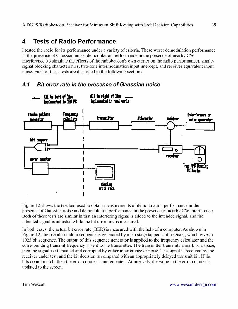
4.1 Bit error rate in the presence of Gaussian noise
Figure 12 shows the test bed used to obtain measurements of demodulation performance in the presence of Gaussian noise and demodulation performance in the presence of nearby CW interference. Both of these tests are similar in that an interfering signal is added to the intended signal, and the intended signal is adjusted while the bit error rate is measured.
In both cases, the actual bit error rate (BER) is measured with the help of a computer. As shown in Figure 12, the pseudo random sequence is generated by a ten stage tapped shift register, which gives a 1023 bit sequence. The output of this sequence generator is applied to the frequency calculator and the corresponding transmit frequency is sent to the transmitter. The transmitter transmits a mark or a space, then the signal is attenuated and corrupted by either interference or noise. The signal is received by the receiver under test, and the bit decision is compared with an appropriately delayed transmit bit. If the bits do not match, then the error counter is incremented. At intervals, the value in the error counter is updated to the screen.
Tim Wescott www.wescottdesign.com

A DGPS/Radiobeacon Receiver for Minimum Shift Keying with Soft Decision Capabilities 40
The following procedure is used to measure the BER vs. signal to (Gaussian) noise ratio (SNR). First, the audio output of the radio is connected to a true RMS reading voltmeter. Then the AGC circuit is defeated, and the radio is connected to a generator of wideband RF Gaussian noise. The IF gain is adjusted until the RMS noise voltage at the the audio output is some convenient value (I used 1V). Next, the noise generator is switched of and the transmitter turned on. The transmitter output is adjusted until the RMS signal voltage is equal to what was established by the noise generator. Finally, the AGC is enabled, and the BER and SNR are measured and recorded for various settings of the transmitter attenuator.
In order to compare the measured performance with the theoretically optimum performance, we must know the relationship that gives Eb and N o given the audio RMS voltage. The filter transmission characteristics (from Figure 2.4) were converted from graphical form to numerical data at 50Hz intervals. This set of data was used to calculate the audio RMS as a function of N o and the audio RMS as a function of Eb . Ultimately, it was found that at a SNR of 0dB the Eb/N o ratio is 0.7dB.
As mentioned in chapter 3, there is a trade off between the carrier loop bandwidth and its acquisition time. To get some data on the effect of carrier loop bandwidths, these tests were conducted for various carrier loop bandwidths. In all cases, the clock loop bandwidth was held constant at 2.76rad/sec.
SNR BER BER BER
(dB) theoretical K ca=2−8
K=5.5rad / secK ea=2−6
K=22rad /sec
10 1.65∗10−6 2.07∗10−5 7.3∗10−5
8 1.41∗10−4 5.0∗10−4 1.00∗10−3
6 2.5∗10−3 4.8∗10−3 7.4∗10−3
4 .0162 .0239 .02852 .055 .072 .0830 .121 .133 .155-2 .203 .222 .254-4 .282 .30 .33-6 .35 .37 .39
Table 2: Bit error rate vs. SNR for various carrier loop bandwidths
Tim Wescott www.wescottdesign.com
A DGPS/Radiobeacon Receiver for Minimum Shift Keying with Soft Decision Capabilities 41
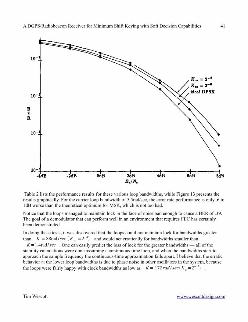
Table 2 lists the performance results for these various loop bandwidths, while Figure 13 presents the results graphically. For the carrier loop bandwidth of 5.5rad/sec, the error rate performance is only .6 to 1dB worse than the theoretical optimum for MSK, which is not too bad.
Notice that the loops managed to maintain lock in the face of noise bad enough to cause a BER of .39. The goal of a demodulator that can perform well in an environment that requires FEC has certainly been demonstrated.
In doing these tests, it was discovered that the loops could not maintain lock for bandwidths greater than K = 88rad /sec K ca =2−4 and would act erratically for bandwidths smaller than
K=1.4rad / sec . One can easily predict the loss of lock for the greater bandwidths — all of the stability calculations were done assuming a continuous time loop, and when the bandwidths start to approach the sample frequency the continuous-time approximation falls apart. I believe that the erratic behavior at the lower loop bandwidths is due to phase noise in other oscillators in the system, because the loops were fairly happy with clock bandwidths as low as K=.172 rad / sec K cl=2−13 .
Tim Wescott www.wescottdesign.com
A DGPS/Radiobeacon Receiver for Minimum Shift Keying with Soft Decision Capabilities 42
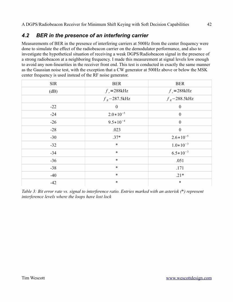
4.2 BER in the presence of an interfering carrierMeasurements of BER in the presence of interfering carriers at 500Hz from the center frequency were done to simulate the effect of the radiobeacon carrier on the demodulator performance, and also to investigate the hypothetical situation of receiving a weak DGPS/Radiobeacon signal in the presence of a strong radiobeacon at a neighboring frequency. I made this measurement at signal levels low enough to avoid any non-linearities in the receiver front end. This test is conducted in exactly the same manner as the Gaussian noise test, with the exception that a CW generator at 500Hz above or below the MSK center frequency is used instead of the RF noise generator.
SIR BER BER
(dB) f r=288kHz f r=288kHz
f R−287.5kHz f R−288.5kHz
-22 0 0
-24 2.0∗10−5 0
-26 9.5∗10−4 0
-28 .023 0
-30 .37* 2.6∗10−5
-32 * 1.0∗10−3
-34 * 6.5∗10−3
-36 * .051-38 * .171-40 * .21*-42 * *
Table 3: Bit error rate vs. signal to interference ratio. Entries marked with an asterisk (*) represent interference levels where the loops have lost lock
Tim Wescott www.wescottdesign.com

A DGPS/Radiobeacon Receiver for Minimum Shift Keying with Soft Decision Capabilities 43
Table 3 lists the results of this test for interfering frequencies that are 500Hz above and 500Hz below the desired receive frequency. Figure 14 presents these results graphically. When the data was taken at high error rates the demodulator took a long time to recover from the interference, which suggests that the input interference affects the phase-lock loops. Notice that the error rate goes from very good to horrible in a very small span of input power. This is most likely because the interfering signal overwhelms the squaring function in the phase locked loops at this point. Also notice that the resistance to this interference is 10dB better when the interference is on the low side of the signal. When the interference is 500Hz below the carrier at RF, it hits a frequency of l500Hz at audio, which places it at the sampling frequency of the demodulator. After sampling, this interference is very close to DC, and should be modulated out of existence in the phase-lock loops.
Tim Wescott www.wescottdesign.com
A DGPS/Radiobeacon Receiver for Minimum Shift Keying with Soft Decision Capabilities 44
4.3 3rd Order Inter modulation Performance
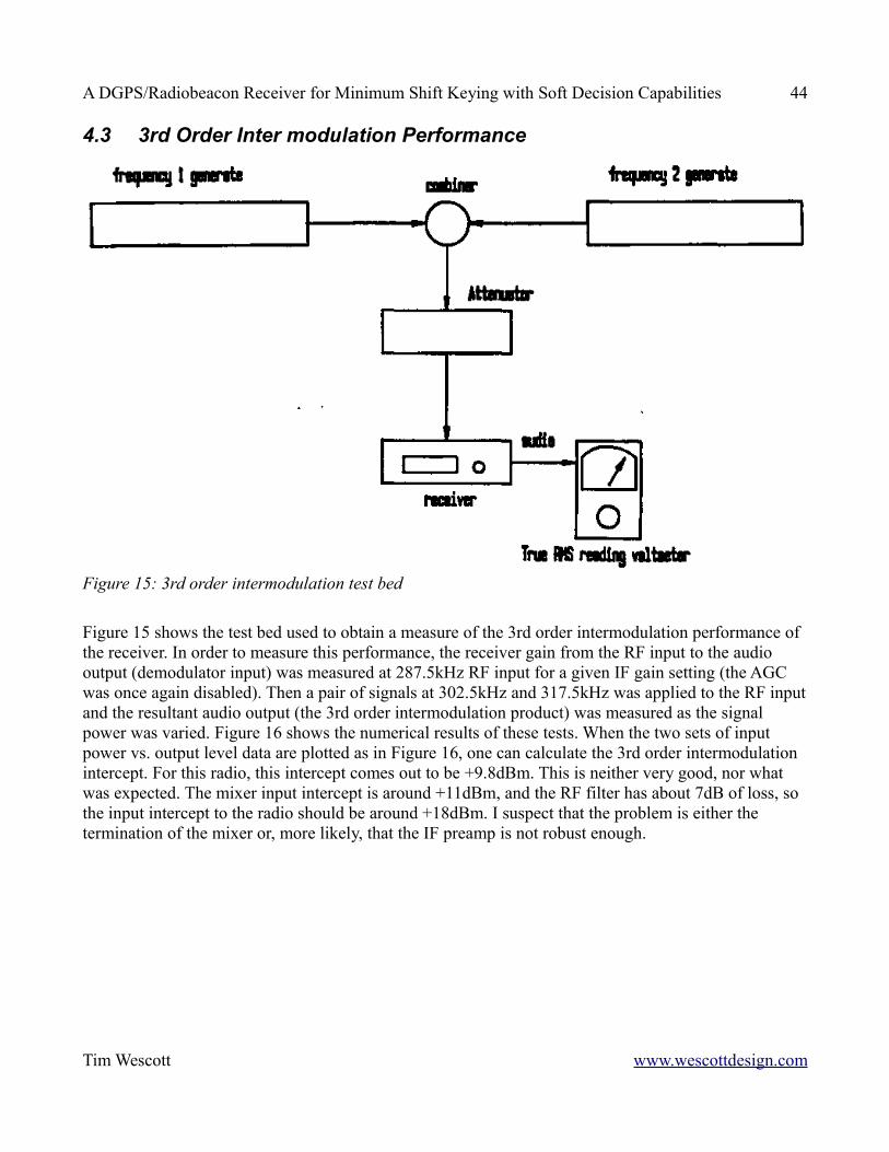
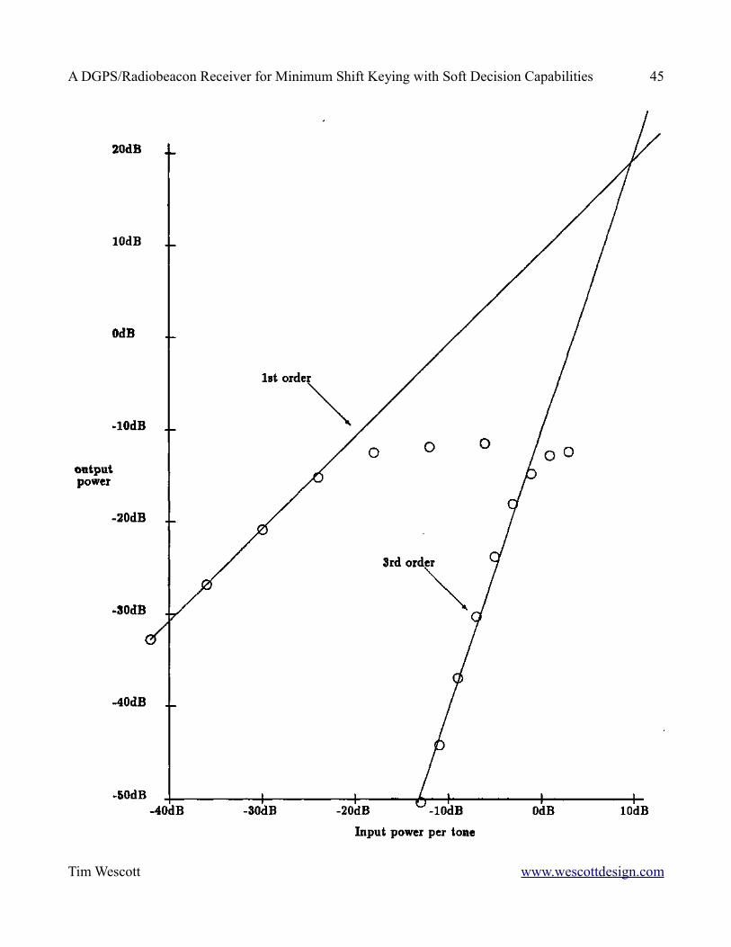
Figure 15 shows the test bed used to obtain a measure of the 3rd order intermodulation performance of the receiver. In order to measure this performance, the receiver gain from the RF input to the audio output (demodulator input) was measured at 287.5kHz RF input for a given IF gain setting (the AGC was once again disabled). Then a pair of signals at 302.5kHz and 317.5kHz was applied to the RF input and the resultant audio output (the 3rd order intermodulation product) was measured as the signal power was varied. Figure 16 shows the numerical results of these tests. When the two sets of input power vs. output level data are plotted as in Figure 16, one can calculate the 3rd order intermodulation intercept. For this radio, this intercept comes out to be +9.8dBm. This is neither very good, nor what was expected. The mixer input intercept is around +11dBm, and the RF filter has about 7dB of loss, so the input intercept to the radio should be around +18dBm. I suspect that the problem is either the termination of the mixer or, more likely, that the IF preamp is not robust enough.
Tim Wescott www.wescottdesign.com
Figure 15: 3rd order intermodulation test bed
A DGPS/Radiobeacon Receiver for Minimum Shift Keying with Soft Decision Capabilities 45
Tim Wescott www.wescottdesign.com
A DGPS/Radiobeacon Receiver for Minimum Shift Keying with Soft Decision Capabilities 46
4.4 Receiver Noise Floor
The test setup in Figure 17 was used to measure the noise characteristics of the receiver. The receiver AGC was disabled, and a small signal was injected to the receiver at its RF port, and the signal magnitude was adjusted until the output at audio was 10dB greater than the output with no signal input. This occurred at an input carrier amplitude of 104.7dBm. From this we can deduce the effective noise power at the input to the receiver. This is
noise power=−104.7dBm−9.5dB=−114.2dBm
. This is also known as the 'noise floor' of the receiver. Knowing the noise floor of the receiver and the effective noise bandwidth of the IF, we can deduce the receiver noise figure:
NF = 168dBmnoise floor−10log Bi= 168dBm−114.2dBm−10log490
= 27dB
Notice that this is not a very good noise figure, but since we are putting the antenna coupler before the RF input to the radio, we can reduce the overall effective input noise by increasing the amplification in the antenna coupler. Overall, the tests of demodulator performance were very encouraging, and the tests of the basic radio performance were rather disappointing. In a way this is not surprising. We ended up expending much more effort on the demodulator design for this radio than we did on the basic radio itself. I think that were one to implement this radio as a practical design, some design effort should be expended to make the radio a little more robust and a little less noisy.
Tim Wescott www.wescottdesign.com
A DGPS/Radiobeacon Receiver for Minimum Shift Keying with Soft Decision Capabilities 47
5 Summary, Some Comments on Soft Bit Decisions, and Further Work
5.1 SummaryI have described a radio receiver built to receive MSK in the 285-325kHz bands. This receiver does this job well. The most notable features of this receiver are its ability to be modified for soft bit decisions, its ability to maintain demodulator lock for very high noise levels, and the microprocessor based demodulator, which is by its nature very flexible.
5.2 Some Comments on Soft Bit DecisionsThe original aim of the work in this thesis was to develop a radio/demodulator combination that could give soft bit decisions (or generate side information - the two are equivalent). While this goal was not achieved, quite a lot of groundwork has been done in the development of hardware and software to get the job done.
According to [15], the soft decision will be sufficient if it is some one-to-one mapping of the probability that a zero was transmitted given the signal received at the demodulator, I will represent this by P(0|s). The easiest such one-to-one mapping that I can think of is an estimate of P(0|s) itself. Note that in the case of a hard bit decision, this probability estimate takes only two values, and becomes the output of the demodulator.
There are two basic ways that soft decisions can be made. One is to extract information about P(0|s) directly from the input to the demodulator. The other is to monitor some other (hopefully empty) channel to detect noise bursts, and use this auxiliary information along with the demodulator output to calculate P(0|s).
5.2.1 The Auxiliary Channel MethodIn the case of ordinary white Gaussian noise, it is useless to use the auxiliary channel method, because the noise processes received in two spectrally disjoint channels will be independent. In the case of atmospheric noise, however, it has shown experimentally that this is not the case [10]. Specifically, the instantaneous noise power of the two channels show positive correlation. This means that a side information generator using an auxiliary channel could be as simple as monitoring the noise power in the auxiliary channel and tagging the output bits as errors when the auxiliary channel noise power exceeds some threshold. The drawback to the auxiliary channel method is that one needs to have an auxiliary channel available. Such a channel is not available on this radio. Furthermore, it would be expensive to build a radio with such an auxiliary channel.
5.2.2 The In-Channel MethodAlthough it is not immediately apparent, there is quite a bit of information about P(0|s) at the input to the demodulator. Again, in the case of ordinary white Gaussian noise, all of this information will be available at the output of the demodulator (i.e., the only processing needed is that provided by the
Tim Wescott www.wescottdesign.com
A DGPS/Radiobeacon Receiver for Minimum Shift Keying with Soft Decision Capabilities 48
demodulator itself). The treatment given in [15] for soft-decision processes gives a good example of the processing necessary for Gaussian noise. In the case of atmospheric noise, there is more information about P(0|s) at the input to the demodulator than at the output.
Tim Wescott www.wescottdesign.com

A DGPS/Radiobeacon Receiver for Minimum Shift Keying with Soft Decision Capabilities 49
Tim Wescott www.wescottdesign.com
Figure 18: P(0|s) vs. incoming signal level for various incoming signal levels and atmospheric conditions

A DGPS/Radiobeacon Receiver for Minimum Shift Keying with Soft Decision Capabilities 50
If we ignore the time structure of the atmospheric noise, then P(0|s) depends only on s, the output of the demodulator, and we can just inspect this output for each bit to decide on our estimate of P(0|s). Figure18 shows P(0|s) for various input signal strengths and weather conditions, using the probability densities for atmospheric noise developed in [10]. If we examine the plots of Figure 18, several things become apparent: First, on a semi-log plot, the shape of the curves do not change for varying signal strengths. Second, on a semi-log plot, the curves are symmetrical about the incoming signal strength.
The shape of the plots in Figure 18 suggest a method for estimating P(0|s). If we know the signal strength, we can divide the demodulator output by the signal strength and get a normalized signal that can be applied to a look-up table to get a quantized estimate of .P(0|s). We notice that with only one look-up table set up for tropical and frontal conditions, this method will be inaccurate for the quiet and quiet-night conditions. However, further thought will reveal that while the estimate will be inaccurate, it will still be a monotonic function of P(0|s), and the raw error rate will be better anyway, so the accuracy is not as necessary.
Unfortunately, the calculations of the the expected value of the absolute value of the signal (E{|z|}) has a bias that changes with signal strength and noise conditions. This means that if we depend on an estimate of the signal strength based on the average of the absolute value of the signal, our estimate of the signal strength will be similarly biased, and our P(0|s) estimate will be flawed. However, if the absolute value of the signal is truncated at twice the signal strength, the bias is removed, which suggests a mechanism to estimate the signal strength accurately.
Figure 19 shows a proposed post-demodulator processor that would take the output of the demodulator and process it into an estimate.
5.3 Suggestions for Further WorkThis radio lacks the ability to make soft decisions in non-Gaussian noise. The greatest area of work that remains to be done with this radio is to develop a soft decision post-processor for the demodulator.
No effort was made with this radio to design the phase lock loops to be optimum in atmospheric noise. It is suggested in [10] that the correct use of non-linearities in the phase lock loop signal path could improve the loop performance.
No effort was made to investigate schemes for demodulation at baud rates lower than 400 baud. While it is straightforward to modify the demodulator algorithm into an optimum demodulator for Gaussian
Tim Wescott www.wescottdesign.com

A DGPS/Radiobeacon Receiver for Minimum Shift Keying with Soft Decision Capabilities 51
noise at any baud late lower than 400, the problem arises that the demodulator is no longer optimum for atmospheric noise. Also, the effect that optimum demodulation has on the soft-decision properties of the demodulator should be investigated.
Tim Wescott www.wescottdesign.com
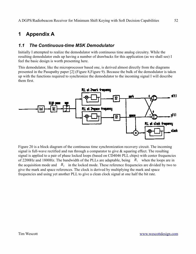
A DGPS/Radiobeacon Receiver for Minimum Shift Keying with Soft Decision Capabilities 52
1 Appendix A
1.1 The Continuous-time MSK DemodulatorInitially I attempted to realize the demodulator with continuous time analog circuitry. While the resulting demodulator ends up having a number of drawbacks for this application (as we shall see) I feel the basic design is worth presenting here.
This demodulator, like the microprocessor based one, is derived almost directly from the diagrams presented in the Pasupathy paper [2] (Figure 8,Figure 9). Because the bulk of the demodulator is taken up with the functions required to synchronize the demodulator to the incoming signal I will describe them first.
Figure 20 is a block diagram of the continuous time synchronization recovery circuit. The incoming signal is full-wave rectified and run through a comparator to give & squaring effect. The resulting signal is applied to a pair of phase locked loops (based on CD4046 PLL chips) with center frequencies of 2200Hz and 1800Hz. The bandwidth of the PLLs are adaptable, being B1 when the loops are in the acquisition mode and B2 in the locked mode. These reference frequencies are divided by two to give the mark and space references. The clock is derived by multiplying the mark and space frequencies and using yet another PLL to give a clean clock signal at one half the bit rate.
Tim Wescott www.wescottdesign.com
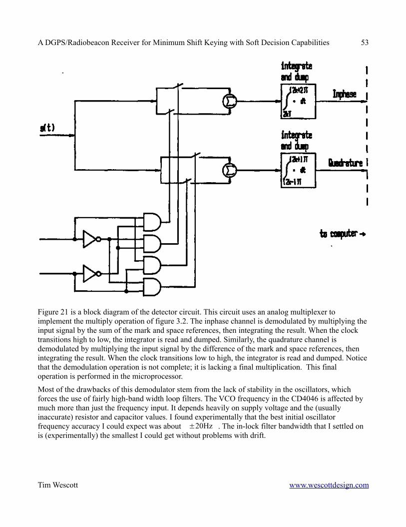
A DGPS/Radiobeacon Receiver for Minimum Shift Keying with Soft Decision Capabilities 53
Figure 21 is a block diagram of the detector circuit. This circuit uses an analog multiplexer to implement the multiply operation of figure 3.2. The inphase channel is demodulated by multiplying the input signal by the sum of the mark and space references, then integrating the result. When the clock transitions high to low, the integrator is read and dumped. Similarly, the quadrature channel is demodulated by multiplying the input signal by the difference of the mark and space references, then integrating the result. When the clock transitions low to high, the integrator is read and dumped. Notice that the demodulation operation is not complete; it is lacking a final multiplication. This final operation is performed in the microprocessor.
Most of the drawbacks of this demodulator stem from the lack of stability in the oscillators, which forces the use of fairly high-band width loop filters. The VCO frequency in the CD4046 is affected by much more than just the frequency input. It depends heavily on supply voltage and the (usually inaccurate) resistor and capacitor values. I found experimentally that the best initial oscillator frequency accuracy I could expect was about ±20Hz . The in-lock filter bandwidth that I settled on is (experimentally) the smallest I could get without problems with drift.
Tim Wescott www.wescottdesign.com

A DGPS/Radiobeacon Receiver for Minimum Shift Keying with Soft Decision Capabilities 54
2 Appendix B
2.1 Receiver Software
This software was written for the Motorola 68HC11 microprocessor. The following is a complete listing of the program that runs the receiver.
************************************************************************** ** Radio version 3.12 ** ** Tim Wescott April 6, 1990 ** ** This is the initial, experimental version of the firmware for ** a differential GPS receiver being built for Per Enge at Worcester ** Polytechnic Institute. The firmware is for a real-time controller ** that is embedded into a fairly standard receiver capable of ** receiving 400 baud MSK data in the 285kHz - 325kHz band. Because ** the tasks are time critical and event driven, the firmware is ** almost entirely interrupt driven. ** ** The functions that this computer in providing are: ** ** Monitor the frequency input knob, and output ** frequency changes to the display and the synthesizers ** ** Implement the demodulator in software, with variable ** loop bandwidth. ** ** Send the bit decisions out to a host computer via ** the RS232 transmitter. ** **************************************************************************
* This section contains the declarations for all of the static* variables and buffers needed by the program
* debounce constantsdbtime equ $100 * 128us delaytimeout equ $2000synofst equ 500+911 * synth setting for 250 kHz rx* with new filterdspofst equ $50 * low byte of 250kHz offsettimer equ $0800 * timeout setting
Tim Wescott www.wescottdesign.com
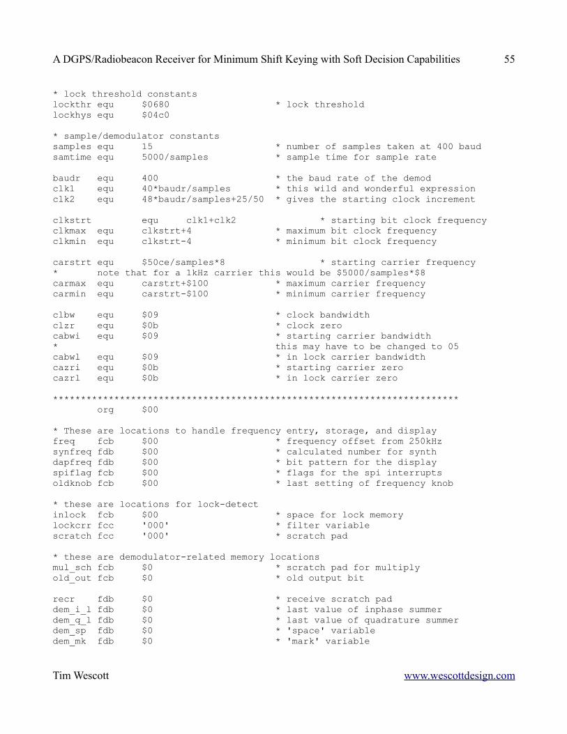
A DGPS/Radiobeacon Receiver for Minimum Shift Keying with Soft Decision Capabilities 55
* lock threshold constantslockthr equ $0680 * lock thresholdlockhys equ $04c0
* sample/demodulator constantssamples equ 15 * number of samples taken at 400 baudsamtime equ 5000/samples * sample time for sample rate
baudr equ 400 * the baud rate of the demodclk1 equ 40*baudr/samples * this wild and wonderful expressionclk2 equ 48*baudr/samples+25/50 * gives the starting clock increment
clkstrt equ clk1+clk2 * starting bit clock frequencyclkmax equ clkstrt+4 * maximum bit clock frequencyclkmin equ clkstrt-4 * minimum bit clock frequency
carstrt equ $50ce/samples*8 * starting carrier frequency* note that for a 1kHz carrier this would be $5000/samples*$8carmax equ carstrt+$100 * maximum carrier frequencycarmin equ carstrt-$100 * minimum carrier frequency
clbw equ $09 * clock bandwidthclzr equ $0b * clock zerocabwi equ $09 * starting carrier bandwidth* this may have to be changed to 05cabwl equ $09 * in lock carrier bandwidthcazri equ $0b * starting carrier zerocazrl equ $0b * in lock carrier zero
************************************************************************* org $00
* These are locations to handle frequency entry, storage, and displayfreq fcb $00 * frequency offset from 250kHzsynfreq fdb $00 * calculated number for synthdapfreq fdb $00 * bit pattern for the displayspiflag fcb $00 * flags for the spi interruptsoldknob fcb $00 * last setting of frequency knob
* these are locations for lock-detectinlock fcb $00 * space for lock memorylockcrr fcc '000' * filter variablescratch fcc '000' * scratch pad
* these are demodulator-related memory locationsmul_sch fcb $0 * scratch pad for multiplyold_out fcb $0 * old output bit
recr fdb $0 * receive scratch paddem_i_l fdb $0 * last value of inphase summerdem_q_l fdb $0 * last value of quadrature summerdem_sp fdb $0 * 'space' variabledem_mk fdb $0 * 'mark' variable
Tim Wescott www.wescottdesign.com

A DGPS/Radiobeacon Receiver for Minimum Shift Keying with Soft Decision Capabilities 56
dem_spe fdb $0 * 'space' phase error variabledem_mke fdb $0 * 'mark' phase error variabledem_scr fdb $0 * scratch pad
clk_pht fdb $0 * temporary clock storagecar_phe fcc 'pea' * carrier phase errorclk_phe fcc 'pel' * clock phase errorcar_ph fcc 'pha' * current value of carrier phaseclk_ph fcc 'phl' * current value of clock phasecar_inc fcc 'ina' * current value of carrier incrementclk_inc fcc 'inl' * current value of clock increment
car_phu fcc 'capu' * carrier phase updateclk_phu fcc 'clpu' * clock phase updatecar_frq fcc 'cafq' * current value of carrier frequencyclk_frq fcc 'clfq' * current value of clock frequency
*************************************************************************
org $e000 * start of ROM
*this is the look - up table for the display digits
disptab fcb $80, $a6, $48, $42, $26, $12, $10, $c6, $00, $06
* First we need to set some values* we will be doing some loads into the register set
startup ldx #base * base address of registers ldw #$00ff * top of ram
* initialize the serial port
ldaa #$31 * 4800 baud staa baud,x
ldaa #$08 * 8 bit word staa sccr1,x
ldaa #$08 * no interrupts, enable TI staa sccr2,x
ldaa #$3a * set port D directions consistent staa ddrd,x * with serial ports
* initialize the SPI port to 62.5Kbaud, positive clock, normal phase,* interrupts off, port D push - pull
ldaa #$53 staa spcr,x bset portd,x #$20 * reset the latch
* turn on the A/D converter
Tim Wescott www.wescottdesign.com
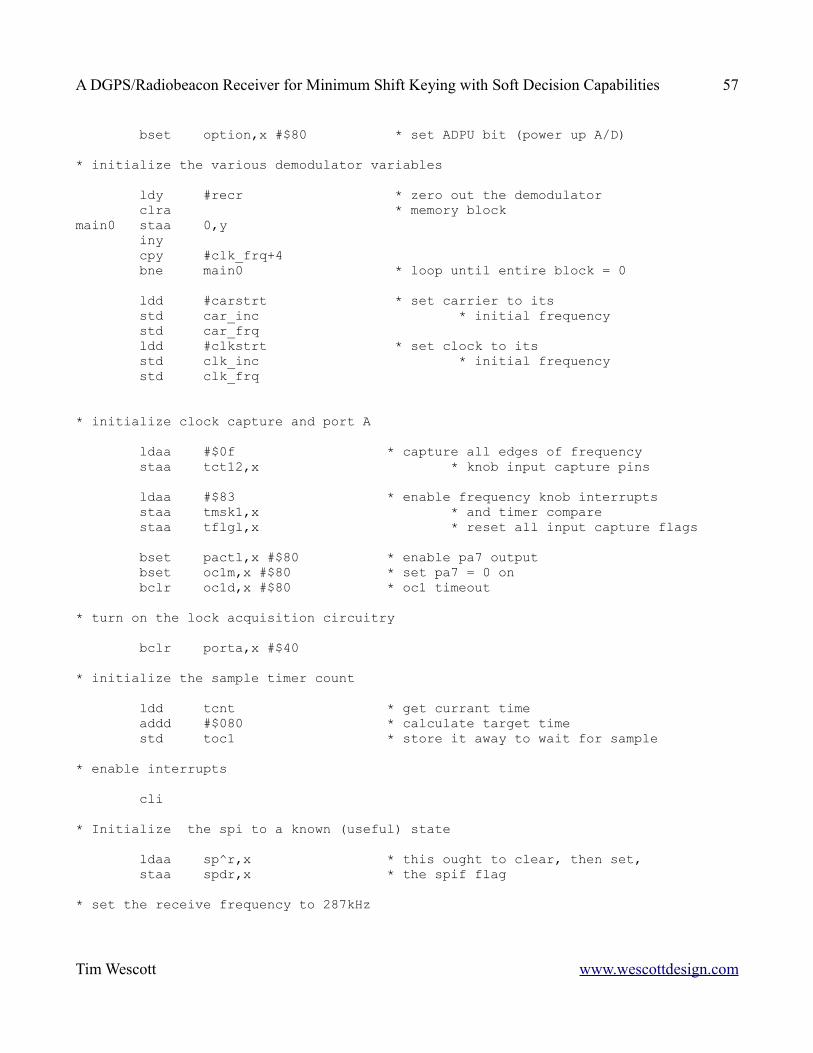
A DGPS/Radiobeacon Receiver for Minimum Shift Keying with Soft Decision Capabilities 57
bset option,x #$80 * set ADPU bit (power up A/D)
* initialize the various demodulator variables
ldy #recr * zero out the demodulator clra * memory blockmain0 staa 0,y iny cpy #clk_frq+4 bne main0 * loop until entire block = 0
ldd #carstrt * set carrier to its std car_inc * initial frequency std car_frq ldd #clkstrt * set clock to its std clk_inc * initial frequency std clk_frq
* initialize clock capture and port A
ldaa #$0f * capture all edges of frequency staa tct12,x * knob input capture pins
ldaa #$83 * enable frequency knob interrupts staa tmsk1,x * and timer compare staa tflgl,x * reset all input capture flags
bset pactl,x #$80 * enable pa7 output bset oc1m,x #$80 * set pa7 = 0 on bclr oc1d,x #$80 * oc1 timeout
* turn on the lock acquisition circuitry
bclr porta,x #$40
* initialize the sample timer count
ldd tcnt * get currant time addd #$080 * calculate target time std toc1 * store it away to wait for sample
* enable interrupts
cli
* Initialize the spi to a known (useful) state
ldaa sp^r,x * this ought to clear, then set, staa spdr,x * the spif flag
* set the receive frequency to 287kHz
Tim Wescott www.wescottdesign.com
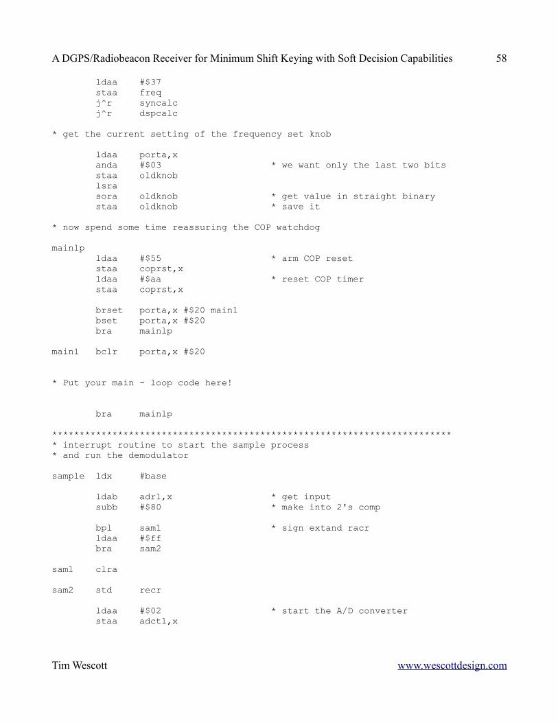
A DGPS/Radiobeacon Receiver for Minimum Shift Keying with Soft Decision Capabilities 58
ldaa #$37 staa freq j^r syncalc j^r dspcalc
* get the current setting of the frequency set knob
ldaa porta,x anda #$03 * we want only the last two bits staa oldknob lsra sora oldknob * get value in straight binary staa oldknob * save it
* now spend some time reassuring the COP watchdog
mainlp ldaa #$55 * arm COP reset staa coprst,x ldaa #$aa * reset COP timer staa coprst,x
brset porta,x #$20 main1 bset porta,x #$20 bra mainlp
main1 bclr porta,x #$20
* Put your main - loop code here!
bra mainlp
************************************************************************** interrupt routine to start the sample process* and run the demodulator
sample ldx #base
ldab adr1,x * get input subb #$80 * make into 2's comp
bpl sam1 * sign extand racr ldaa #$ff bra sam2
sam1 clra
sam2 std recr
ldaa #$02 * start the A/D converter staa adctl,x
Tim Wescott www.wescottdesign.com
A DGPS/Radiobeacon Receiver for Minimum Shift Keying with Soft Decision Capabilities 59
ldd tocl,x * reset the timer for the addd #samtime * next interval std toc1,x bclr tflf1,x #$7f * clear the ocif flag
A_Dco€p ldd clk_ph * update clock phase addd clk_inc * into temporary space std car_ph
adda clk_pht * get mark phase
bpl €_Dc01 * multiply by sign of sin mark ldd dem_mk subd recr std dem_mk bra A_Dc02
A_Dc01 ldd dem_mk addd recr std dem_mk
A_Dc02 ldaa car_ph suba clk_pht * get space phase
bpl A_Dc03 * multiply by sign of sin space ldd dem_sp subd recr std dem_sp bra A_Dc04
A_Dc03 ldd dem_sp addd recr std dem_sp
A_Dc04 ldaa recr+1 * get received input bpl A_Dc05 * get absolute value nega
A_Dc05 tab * and square mul
std recr * stash it away
ldaa car_ph * get mark phase adda clk_pht
bita #$40 * get sign of twice mark phase beq A_Dc06 * multiply by twice mark phase ldd dem_mke * and subtract addd recr std dem_mke bra A_Dc07
A_Dc06 ldd dem_mke
Tim Wescott www.wescottdesign.com
A DGPS/Radiobeacon Receiver for Minimum Shift Keying with Soft Decision Capabilities 60
subd recr std dem_mke
A_Dc07 ldaa car_ph * get space phase suba clk_pht
bita #$40 * get sign of twice space phase beq A_Dc08 * multiply by twice space phase ldd dem_spe * and subtract addd recr std dem_spe bra A_Dc09
A_Dc08 ldd dem_spe subd recr std dem_spe
A_Dc09 ldaa clk_pht * check for clock rolled over eora clk_ph * if bit 6 has changed, then cloc bita #$40 * has rolled over bne A_Dc0A_Dc0A_Dc00 ldd clk_pht std clk_ph ldaa clk_inc+2 * make up for 2-byte add in main loop ldab #400*samples/baudr mul * extra increment to add addd clk_ph+1 std clk_ph+1 ldaa clk_ph adca #0 staa clk_ph * stash it away permanently
ldaa car_inc+2 * make up for 2-byte add in main loop ldab #400*samples/baudr mul * extra increment to add addd car_ph+1 std car_ph+1 ldaa car_ph adca #0 staa car_ph * stash it away permanently
brset clk_ph #$40 A_Dc1 beet porta,x #$08 ldd dem_sp subd dem_mk addd dem_q_l bra A_Dc2
A_Dc1 bclr porta,x #$08 ldd dem_mk addd dem_sp addd dem_i_l * get bit to send
Tim Wescott www.wescottdesign.com
A DGPS/Radiobeacon Receiver for Minimum Shift Keying with Soft Decision Capabilities 61
A_Dc2 tab sorb old_out andb #$80 staa old_out * save old demod output pshb
ldd dem_mk * shift all demods addd dem_sp std dem_i_l
ldd dem_sp subd dem_mk std dem_q_l
ldd dem_mke * get carrier error addd dem_spe std car_phe+1
ldd dem_mke * get clock error subd dem_spe std clk_phe+1
ldd #0 * zero out channel accumulators std dem_mk std dem_sp std dem_mke std dem_spe
cli * it's safe to interrupt
pulbA_Dc3 brclr scsr,x #$80 A_Dc3 * make rs232 available stab scdr,x * and transmit
A_Dc8 ldaa clk_phe+1 * sign extend clock error to mab bpl A_dc11 ldaa #$ff bra A_Dc12
A_Dc11 clraA_Dc12 staa clk_phe staa clk_phu
ldaa car_phe+1 * sign extend carrier error bpl A_Dc13 ldaa #$ff bra A_Dc14
A_Dc13 clraA_Dc14 staa car_phe staa sar_phu
ldd car_phe+1 * low pass filter the carrier error std scratch
Tim Wescott www.wescottdesign.com
A DGPS/Radiobeacon Receiver for Minimum Shift Keying with Soft Decision Capabilities 62
ldd lockcrr+1 * update the in lock filter subd lockcrr std lockcrr+1 ldaa lockcrr abca #0 staa lockcrr
ldd scratch * get the absolute value of bpl A_Dc14a * the phase error
ldd #0 subd scratch
A_Dc14a addd lockcrr+1 * low pass filter the absolute value std lockcrr+1 * of the phase error for ldaa #0 * lock info adca lockcrr staa lockcrr
* Mighty Machineria's spaghetti code city!* or, I wish I had a faster processorA_Dc14e ldd lockcrr * now get filter value & check brset porta,x #$40 A_Dc14c * branch if loop locked subd #lockthr-lockhys * check if loop should lock bhi A_Dc14f bset porta,x #$40 * if should lock, lock bra A_Dc14g
A_Dc14c subd #lockthr * check if loop should inlock bla A_Dc14g bclr porta,x #$40 * if should unlock, unlock
A_Dc14f ldaa #cabwi * unlocked loop gain bra A_Dc14d
A_Dc14g ldaa #cabwl * locked loop gain
A_Dc14d ldy #car_phe * multiply carrier phase jar shift_r * by high-frequency
ldy #clk_phe * multiply clock phase ldaa #clbw jar shift_r
ldaa #$3 ldy #0
A_Dc15 ldab car_phe,y * set car_phu = car_phe stab car_phu+1,y * and clk_phu = clk_phe ldab clk_phe,y stab alk_phu+1,y iny deca
Tim Wescott www.wescottdesign.com
A DGPS/Radiobeacon Receiver for Minimum Shift Keying with Soft Decision Capabilities 63
hne A_Dc15
ldy #car_phu+1 * multiply carrier phase ldd lockcrr * by zero frequency cpd #lockthr+lockhys * use zero frequency if bls A_Dc15a * close to lock ldaa #cazri * else use high frequency bra A_Dc15bA_Dc15a ldaa #cazrlA_Dc15b jar shift_r
sec ldd car_frq+2 * update the carrier frequency abcb car_phu+3 * with carry from phase error sbca car_phu+2 std car_frq+2 ldd car_frq sbcb car_phu+1 sbca car_phu std car_frq
cpd #carmax * check for carrier overflow bls A_Dc16 ldd #carmax * if overflow, set to overflow std car_frq bra A_Dc17
A_Dc16 cpd #carmin * check for carrier underflow bhs A_Dc17 ldd #carmin * if underflow set to minimum std car_frq
A_Dc17 ldy #clk_phu+1 * multiply clock phase ldaa #clzr * by zero frequency jer shift_r
sec ldd clk_frq+2 * update the clock frequency sbcb clk_phu+3 * with carry from phase error sbca clk_phu+2 std clk_frq+2 ldd clk_frq sbcb clk_phu+1 sbca clk_phu std clk_frq
cpd #clkmax * check for carrier overflow bls A_Dc18 ldd #clkmax * if overflow, set to maximum std clk_frq bra A_Dc19
A_Dc18 cpd #clkmin * check for carrier underflow bhs A_Dc19
Tim Wescott www.wescottdesign.com
A DGPS/Radiobeacon Receiver for Minimum Shift Keying with Soft Decision Capabilities 64
ldd #clkmin * if underflow, set to minimum std clk_frq
A_Dc19 sei ldd car_frq+1 * update the carrier increment subd car_phe+1 std car_ing+1 ldaa car_frq sbca car_phe staa car_inc
ldd clk_frq+1 * update the clock increment subd clk_phe+1 std clk_ing+1 ldaa clk_frq sbca clk_phe staa clk_inc
rti
************************************************************************** This routine finds (cos(a+b) + cos(a-b))/2 = cos(a)cos(b)* the adguments come in in registers a and b, and are returned in a
cosab aba * get the sum of the phases psha * save 'em sba * get the difference sba ldy #cos_tab * get base of cosine table tab aby * add offset to proper result
ldaa ,y * get cos(a-b)/2
pulb * retrieve the sum ldy #cos_tab * get base aby * add offset adda ,y * get (cos(a-b) + cos(a+b))/2
rts * this takes 50 instruction cycles
************************************************************************** This routine shifts the 3 byte field pointed to y* a-8 places to the right (an 8-bit right shift is assumed)* if a<8 then the field is shifted the appropriate amount to the left
shift_r suba #$08 * line up a beq sh_end * if a = 8 then shift not necessary bmi sh_lft * if a < 8 then shift left
sh_rt asr 0,y * shift one place to the right
Tim Wescott www.wescottdesign.com
A DGPS/Radiobeacon Receiver for Minimum Shift Keying with Soft Decision Capabilities 65
ror 1,y ror 2,y deca bne sh_rt * repeat as necessary bra sh_end
sh_lft asl 2,y * shift one place to the left rol 1,y rol 0,y inca bne sh_lft * repeat as necessary
sh_end rts
*************************************************************************SCIint rti * hold space for this routine
************************************************************************** interrupt routine to service the spi. The two things it needs to send* are the display information and the synthesizer information* the order of importance is:* if display transfer in process, finish it* if synthesizer transfer is in progress, finish it* if synthesizer transfer is pending, start it* if display transfer is pending, start it
SPIint ldx #$1000 * make sure you have the correct index
brclr spiflag #$10 spi1 * if not synth latch, jump bset portd,x #$20 * else latch onto the synthesizer nop nop bclr portd,x #$20 bclr spiflag #$10 * indicate transfer done bra spi0 * and go to finish
spi1 ldaa spar,x * if spi transfer needed, clear spif
brclr spiflag #$04 spi2 * if not synth transfer active, jump ldaa synfreq+1 * else get low-order byte of synth staa spdr,x * and send it bclr spiflag #$04 * indicate transfer done bset spiflag #$10 * set need latch bit bra spi10 * and go to finish
spi2 brclr spiflag #$01 spi3 * if not display transfer active, jump ldaa dspfreq+1 * else get low-order byte of display staa spdr,x * and send it bclr spiflag #$01 * indicate transfer done bra spi0 * and go to finish
spi3 brclr spiflag #$08 spi4 * if not synth transfer pending jump ldaa synfreq * else get high order byte of display
Tim Wescott www.wescottdesign.com
A DGPS/Radiobeacon Receiver for Minimum Shift Keying with Soft Decision Capabilities 66
staa spdr,x * and send it bclr spiflag #$08 * indicate transfer pending bset spiflag #$04 * set transfer pending bra spi0 * and go to finish
spi4 brclr spiflag #$02 spi0 * if not display transfer pending jump ldaa dspfreq * else get high order byte of synth staa spdr,x * and send it bclr spiflag #$02 * indicate transfer pending bset spiflag #$01 * set transfer pending bra spi0 * and go to finish
spi0 brclr spiflag #$1f spi5 * if operation pending, return rti
spi5 bclr spcr,x #$80 * else disable spi interrupts rti
************************************************************************** This interrupt service routine is turned on by the frequency* knob. It must turn on a debounce timer, which causes the computer* to ignore any switch inputs until things settle down
upfdownf ldx #base * point to base of I/O pile
ldd tcnt,x addd #dbtime * delay std toc2,x * set debounce for 80ms bclr tflg1,x #$bf * clear the debounce flag bset tmsk1,x #$40 * disable debounce interrupt bclr tflg1,x #$fc * clear the switch flags
rti
************************************************************************** If the switches are open for 20ms, this routine is activated. It turns* off the repeat interrupt and turns itself off
dbounce ldx #basebclr tmsk1,x #$40 * disable debounce interrupts
ldaa porta,x * get switch settingsanda #$03
staa scratch lara eora scratch * make into binary
tab * save value suba oldknob * get increasing/decreasing info
stab oldknob * save current knob position
Tim Wescott www.wescottdesign.com

A DGPS/Radiobeacon Receiver for Minimum Shift Keying with Soft Decision Capabilities 67
bita #$01 * check for valid knob readbeq dbnc0 * if not valid, ignore
bita #$02 * check for directionbne dbnc1 * if down, decrement frequencyldaa #$01 * else increment frequencyadda freqdaastaa freqbra dbnc2
dbnc1 ldaa #$99 * decrement frequencyadda freqdaastaa freq
dbnc2 jar syncalc * start the synthesizerjar dspcalc * and the displayldaa #$f4 * turn on demod seekstaa lockcrr
dbnc0 rti
************************************************************************** calculate number to load into synthesizer, and start the spi
* calculate the number
syncalc ldaa freq * get bcd offset bytetab * into both accumulators
andb #$f0 * save high digit in Banda #$0f * low digit in A
lsrb * add 10*(high digit) to lowaba * digit, result in Alsrblsrb * (this is quicker than usingaba * MUL instruction)tabldaa #0
lslb * times two for synthesizeraddd #synofst * add to offset for IF and basestd synfreq * frequency and store
* start the spi
bclr spiflag#$14 * clear the transfer in progress flagsbset spiflag#$08 * set the transfer pending flagbset spcr.x #$80 * enable spi interrupts
rts
Tim Wescott www.wescottdesign.com
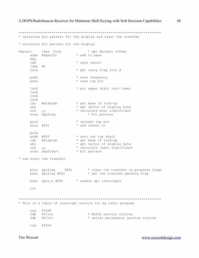
A DGPS/Radiobeacon Receiver for Minimum Shift Keying with Soft Decision Capabilities 68
************************************************************************** calculate bit pattern for the display and start the transfer
* calculate bit pattern for the display
dspcalc ldaa freq * get decimal offsetadda #dspofst * add to basedaatab * save resultldaa #0rola * get carry flag into A
pshb * save frequencypsha * save top bit
lsrb * put upper digit into lowerlsrblsrblsrbldy #disptab * get base of look-upaby * get vector of display byteora ,y * calculate most significantstaa dspfreq * bit pattern
pula * recover top biteora #$01 * and invert it
pulbandb #$0f * zero out top digitldy #disptab * get base of look-upaby * get vector of display byteora ,y * calculate least significantstaa dspfreq+1 * bit pattern
* now start the transfer
bclr spiflag #$01 * clear the transfer in progress flagsbset Spiflag #$02 * set the transfer pending flag
bset spcr,x #$80 * enable spi interrupts
rts
************************************************************************** This is a table of interrupt vectors for my radio program
org $ffd6fdb SCIint * RS232 service routinefdb SPIint * serial peripheral service routine
org $ffe4
Tim Wescott www.wescottdesign.com
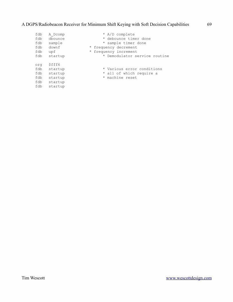
A DGPS/Radiobeacon Receiver for Minimum Shift Keying with Soft Decision Capabilities 69
fdb A_Dcomp * A/D completefdb dbounce * debounce timer donefdb sample * sample timer donefdb downf * frequency decrementfdb upf * frequency incrementfdb startup * Demodulator service routine
org $fff6fdb startup * Various error conditionsfdb startup * all of which require afdb startup * machine resetfdb startupfdb startup
Tim Wescott www.wescottdesign.com
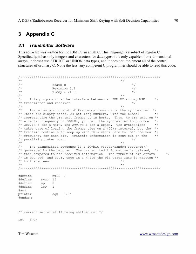
A DGPS/Radiobeacon Receiver for Minimum Shift Keying with Soft Decision Capabilities 70
3 Appendix C
3.1 Transmitter SoftwareThis software was written for the IBM PC in small C. This language is a subset of regular C. Specifically, it has only integers and characters for data types, it is only capable of one-dimensional arrays, it doesn't use STRUCT or UNION data types, and it does not implement all of the control structures of ordinary C. None the less, any competent C programmer should be able to read this code.
/************************************************************************//* *//* erate.c *//* Revision 3.1 *//* Timmy 4-21-90 *//* *//* This program runs the interface between an IBM PC and my MSK *//* transmitter and receiver. *//* *//* Transmissions consist of frequency commands to the synthesizer. *//* These are binary coded, 24 bit long numbers, with the number *//* representing the transmit frequency in hertz. Thus, to transmit on *//* a center frequency of 300kHz, you tell the synthesizer to produce *//* 300.1kHz for a mark, and 299.9kHz for a space. The synthesizer *//* takes care of loading the frequencies on a 400Hz interval, but the *//* transmit routine must keep up with this 400Hz rate to load the new *//* frequency for each bit. Transmit information is sent out on the *//* parallel printer port. *//* *//* The transmitted sequence is a 10-bit pseudo-random sequence*//* generated by the program. The transmitted information is delayed, *//* then compared to the received information. The number of bit errors *//* is counted, and every once in a while the bit error rate is written *//* to the screen. *//* *//************************************************************************/
#define null 0#define sync 15#define up 0#define low 1#asmprinter equ 378h#endasm
/* current set of stuff being shifted out */
int shd;
Tim Wescott www.wescottdesign.com
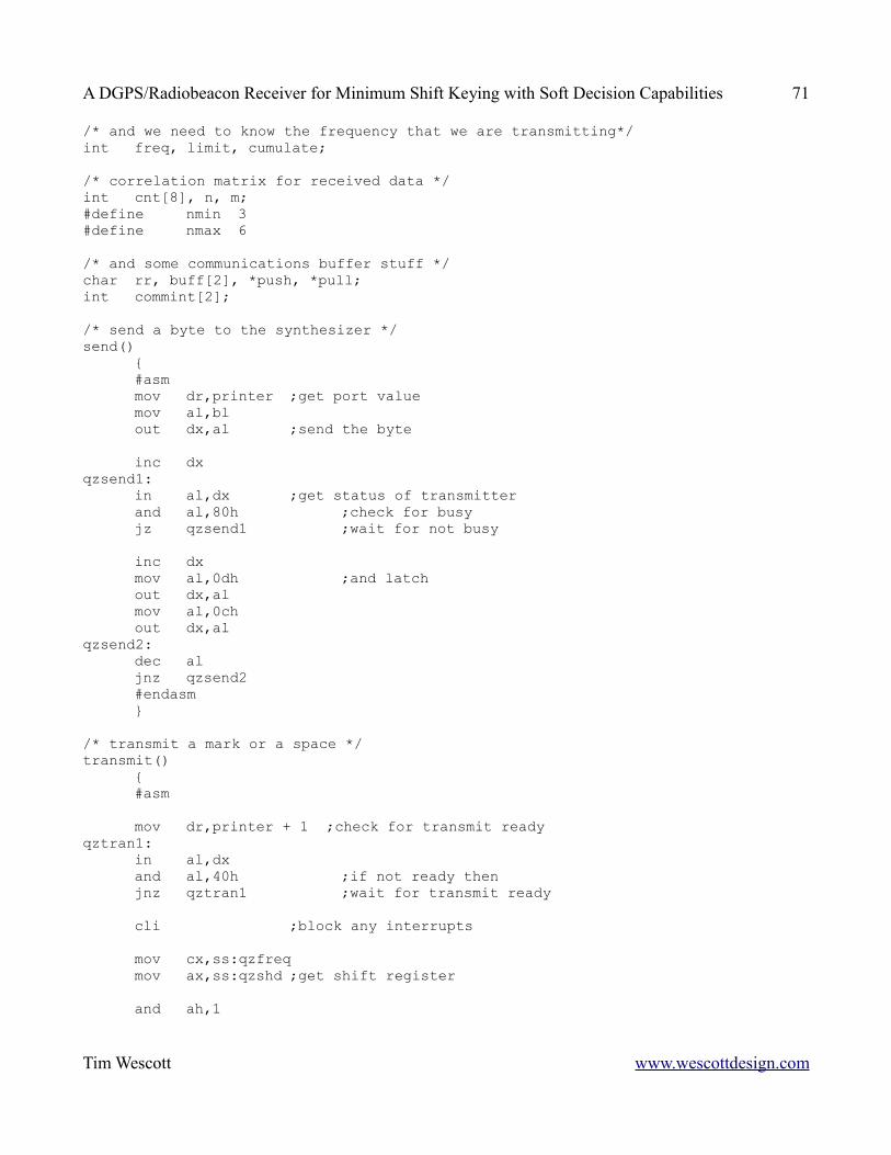
A DGPS/Radiobeacon Receiver for Minimum Shift Keying with Soft Decision Capabilities 71
/* and we need to know the frequency that we are transmitting*/int freq, limit, cumulate;
/* correlation matrix for received data */int cnt[8], n, m;#define nmin 3#define nmax 6
/* and some communications buffer stuff */char rr, buff[2], *push, *pull;int commint[2];
/* send a byte to the synthesizer */send()
{#asmmov dr,printer ;get port valuemov al,blout dx,al ;send the byte
inc dxqzsend1:
in al,dx ;get status of transmitterand al,80h ;check for busyjz qzsend1 ;wait for not busy
inc dxmov al,0dh ;and latchout dx,almov al,0chout dx,al
qzsend2:dec aljnz qzsend2#endasm}
/* transmit a mark or a space */transmit()
{#asm
mov dr,printer + 1 ;check for transmit readyqztran1:
in al,dxand al,40h ;if not ready thenjnz qztran1 ;wait for transmit ready
cli ;block any interrupts
mov cx,ss:qzfreqmov ax,ss:qzshd ;get shift register
and ah,1
Tim Wescott www.wescottdesign.com
A DGPS/Radiobeacon Receiver for Minimum Shift Keying with Soft Decision Capabilities 72
jz qztran2add cx,64h ;if lsb=1 send markjmp qztran3
qztran2:sub cx,64h ;if lsb=0 send space
qztran3:mov bl,4 ;first byte always 4call qzsend
mov bl,ch ;send nextcall qzsendmov bl,cl ;two bytescall qzsend
sti ;reenable interrupts
#andasm}
/* make next entry in random sequence */next()
{#asmmov bp,sp ;this do-hicky implements amov bx,[bp + 2] ;ten-bit shift register sequencemov al,bl ;on the appropriate operandmov cl,3 ;tap on third bitshr al,cland al,1hxor al,bl ;get the new bit to insertand al,1h ;filter out other bitsshl al,1 ;line up to tenth bitshr bx,1 ;shift operandor bh,al ;insert bit#endasm}
/* Get the transmit frequency */getfreq(f)int *f;
{int not_valid;not_valid = 1;while(not_valid)
{puts("enter the transmit frequency in kilohertz");*f = getint(10);puta("\n\r\0");not_valid = (*f >= 327)|(*f <= 262);if (not_valid)
pl("frequency must be between 262kHz and 327kHz");}
Tim Wescott www.wescottdesign.com
A DGPS/Radiobeacon Receiver for Minimum Shift Keying with Soft Decision Capabilities 73
*f = *f*1000 + 500}
/* this is a VERY s^^^^y error handler */error();
/* check for a byte from the receiver and return with it */receive()
{#asm
mov bp,ss:qxpullmov al,qzbuff[bp] ;get current receive characterror bp,1mov ss:qzpull,bpcbwmov bx,ax
#endasm}
/* increment the bit-in-error counter if the bits don't match */count()
{#asm
mov bp,sp ;get a nice little pointermov bx,[bp + 2] ;get receive bit into bland bl,80h ;strip out bitmov ax,ss:qzshd ;get transmit bit into al
mov cx,ss:qznmov bp,cxrol ax,clcmp al,bljs qzcnt1sal bp,1inc qzcnt[bp]
qzcnt1:
#endasm}
/* initialization and interrupt routine for the communications port */comm()
{#asm
push dspush es
mov ax,350ch
Tim Wescott www.wescottdesign.com
A DGPS/Radiobeacon Receiver for Minimum Shift Keying with Soft Decision Capabilities 74
int 21h ;get communications port interrupt vectormov ss:qzcommint,bxmov bx,esmov ss:qzcommint[2],bx
mov dx,csmov ds,dxmov dx,offset rx10mov ax,250chint 21h ;set interrupt vector to interrupt service
mov ax,00c3h ;4800 baud, 1 stop bit, no parity, 8 bit wordmov dx,0int 14h ;initialize the comm port
mov dx,40h ;get segmentmov ds,dxdb 8bh,16h,00,00 ;(mov dr,[0]) get comm port address
cli ;make sure there are no interrupts
add dx,4 ;modem control registermov al,0fh ;DTR, RTS, OUT1, OUT2out dx,al
in al,21h ;get interrupt masksand al,0efh ;turn off comm port maskout 21h,al
sti
;***************** reset the interface ****************
sub dx,3 ;interrupt enable registermov al,0out dx,al
add dx,4 ;line status registerin al,dx
inc dx ;modem status registerin al,dx
db 8bh,16h,00,00 ;(mov dx,[0]) get comm port addressin al,dx ;received character
add dx,2 ;interrupt ID registerin al,dx
dec dx ;enable interrupts on UARTmov al,5 ;received character and rx line statusout dx,al
mov ss:qzpush,00
Tim Wescott www.wescottdesign.com
A DGPS/Radiobeacon Receiver for Minimum Shift Keying with Soft Decision Capabilities 75
mov ss:qzpull,00 ;initialize pointers
mov al,20h ;end-of-interruptout 20h,al
pop espop dsret
;This is the interrupt service routine
rxi0:sti
push dxpush axpush espush dspush bp
mov al,20hout 20h,al ;reenable interrupt controller
mov ax,stack ;all data is in the stack segmentmov es,ax ;(I am using the extra segment here)
mov dx,40h ;get segmentmov ds,dxdb 8bh,16h,00,00 ;(mov dx,[0]) get comm port address
add dx,in al,dxtest al,01jnz rxi1
cmp al,06 ;test for rx line statusjne rxi2add dx,3 ;if line status, read line statusin al,dxjnp rxi1
rxi2: db 8bh,16h,00,00 ;(nov dx,[0]) get comm port addressin al,dx ;assume that other thing is rx registermov bp,es:qzpushmov es:qzbuff[bp],al ;put byte into bufferxor bp,01 ;toggle pointermov es:qzpush,bp
rxi: pop bppop dspop espop axpop dx
Tim Wescott www.wescottdesign.com
A DGPS/Radiobeacon Receiver for Minimum Shift Keying with Soft Decision Capabilities 76
iret
#endasm}
/* set the display for its initial value */initdsp()
{int n;char s[7];clrscreen();
n = 23;while(--n) putchar('-'); /*make a line of dashes*/
n = freq/100; /* convert frequency back to 100Hzs */if (n < 0) n = 3276 + n;else n = 2622 + n ; /* adjust for signed arithmetic */
inttoatr(s,n); /* display number */n = 0;while (++n < 5) a[n] = s[n+1]; /* stick in decimal point */s[4] = '.'; /* for kHz */puts(" transmit frequency =");puts(s);puts("kHz ");
n = 23;while(--n) putchar('-'); /* finish off with more dashes */}
/* turn off interrupts and exit */goodby()
{#asm
cliin al,21hor al,10h ;mask communications interruptout 21h,al
push dsmov ds,ss:qzcommint[0]mov dx,ss:qzcommint[2]mov ax,250chint 21h ;reset interrupt vectorpop ds
mov ax,00c7h ;4800 baud, 1 stop bit, no paritymov dx,0 ;(and turn off interrupts)int 14h ;initialize the comm port
sti
Tim Wescott www.wescottdesign.com
A DGPS/Radiobeacon Receiver for Minimum Shift Keying with Soft Decision Capabilities 77
#endasm
exit();}
main(){int syncflag, running, rx;
getfreq(&freq);initdisp();shd = 1;n = 8;while(--n) cnt[n] = 0;comm();
/* now go into main trancieve loop */while (1)
{
/* if character, see what operator wants */if (pcdoa(11,0))
{/* if character is a space, then reset *//* the cumulative error count */transmit();receive();if (getchar() ++ ' ')
{limit = 0;cumulate = 0;}
else{puts("\n\rdo you wish to stop?");if (getchar() == 'y') goodby();puts("\n\r");getfreq(&freq);initdisp();}
}
m = 20;while (--m) transmit();
/* collect data to find which channel is correct */running = 100;while (running--)
{n = 3;while(++n <= 5)
{transmit();count(receive());
Tim Wescott www.wescottdesign.com
A DGPS/Radiobeacon Receiver for Minimum Shift Keying with Soft Decision Capabilities 78
shd = next(shd);}
}transmit();receive();/* if the sequence is aligned to n=5 then realign */if (cnt[4] > cnt[5]) receive();
transmit();receive();n = 4;cnt[4] = 0;
/* count up the errors in 1000 bits */running = -20;while (++running <= 1000)
{if (running);else m = cnt[4];transmit();count(receive());shd = next(shd);}
cnt[4] = cnt[4] - m;/* check for believable data and *//* add errors to cumulative total */if (cnt[4] < 450)
{cumulate = cumulate + cnt[4];limit++;}
transmit();receive();/* now display, then clear the correlation register */#asm
mov ah,2 ;locate the cursor to the left topmov dx, 0200h ;of screenmov bh, 0 ;page zeroint 10h
#endasmputs("errors per 1000 =");putint(cnt[4]);transmit();receive();
/* and display, then the cumulative register */#asm
mov ah,2mov dx,0400hmov bh, 0 ;page zeroint 10h
#endasmputs("errors per");putint(limit);
Tim Wescott www.wescottdesign.com
A DGPS/Radiobeacon Receiver for Minimum Shift Keying with Soft Decision Capabilities 79
puts("000 =");putint(cumulate);transmit();receive();
/* check for overflow */if (limit > 9999)
{limit = 0;cumulate = 0;}
transmit();receive();
n = 3;while(++n <= 5) cnt[n] = 0;}
}
Tim Wescott www.wescottdesign.com
A DGPS/Radiobeacon Receiver for Minimum Shift Keying with Soft Decision Capabilities 80
4 Appendix D
4.1 Schematics
Tim Wescott www.wescottdesign.com
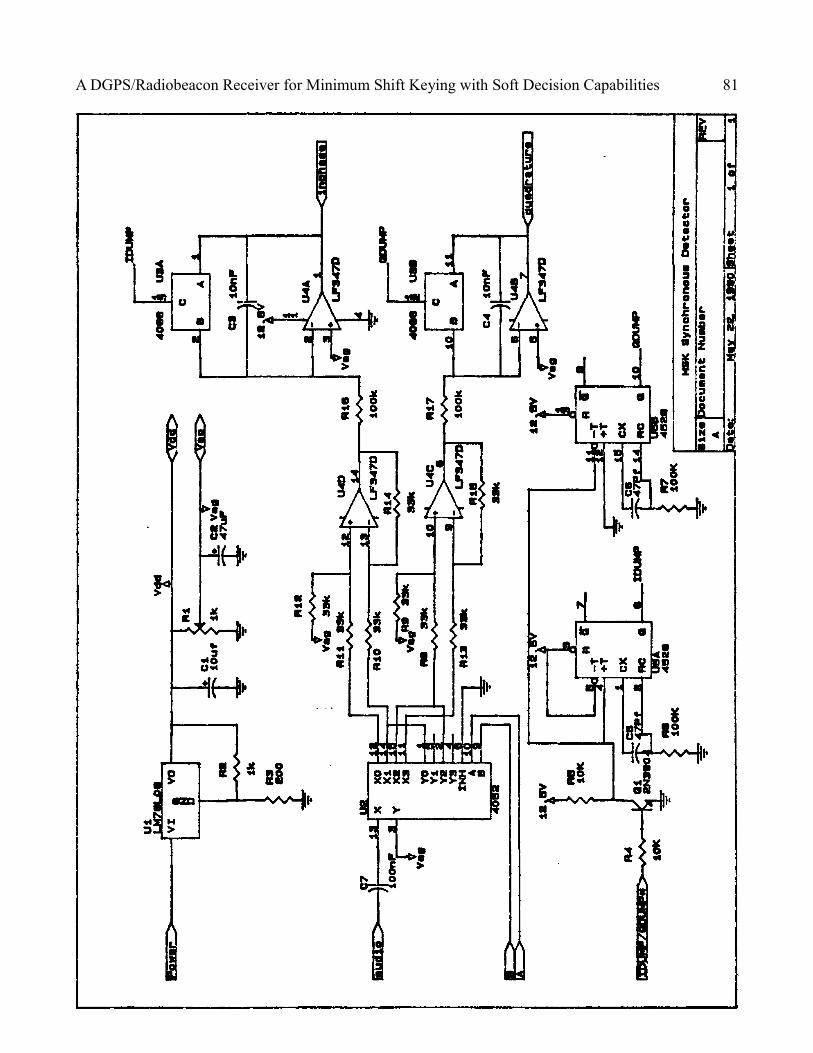
A DGPS/Radiobeacon Receiver for Minimum Shift Keying with Soft Decision Capabilities 81
Tim Wescott www.wescottdesign.com
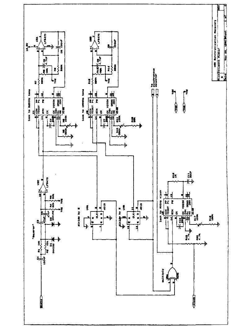
A DGPS/Radiobeacon Receiver for Minimum Shift Keying with Soft Decision Capabilities 82
Tim Wescott www.wescottdesign.com

A DGPS/Radiobeacon Receiver for Minimum Shift Keying with Soft Decision Capabilities 83
Tim Wescott www.wescottdesign.com
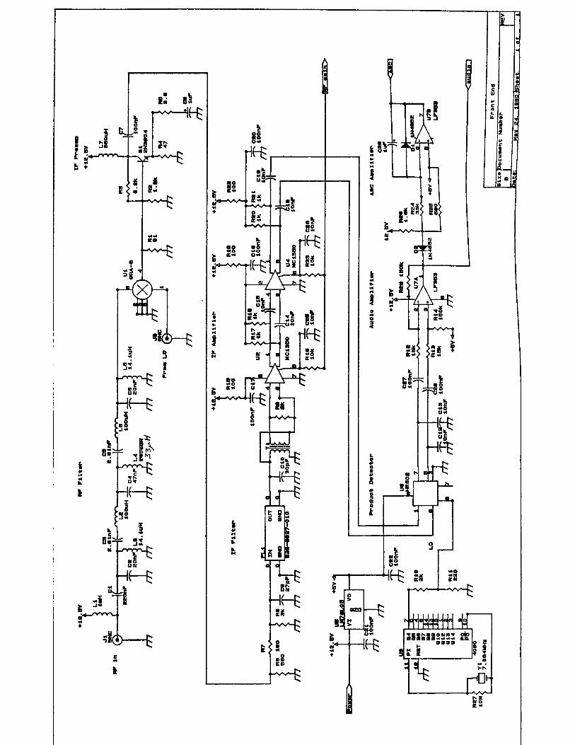
A DGPS/Radiobeacon Receiver for Minimum Shift Keying with Soft Decision Capabilities 84
Tim Wescott www.wescottdesign.com
A DGPS/Radiobeacon Receiver for Minimum Shift Keying with Soft Decision Capabilities 85
Tim Wescott www.wescottdesign.com
A DGPS/Radiobeacon Receiver for Minimum Shift Keying with Soft Decision Capabilities 86
5 Bibliography
[1] R De Buda Coherent demodulation of Frequency-Shift Keying With Low Derivation Ratio
IEEE Transactions, 1972, COM-20, pp. 429-435
[2] S. Pasupathy, Minimum Shift Keying: A Spectrally Efficient Modulation IEEE
Communications Society Magazine, July 1979, Vol. 17, No. 4, pp. 14-22
[3] Floyd Gardner, Phaselock Techniques Second Edition, John Wiley & Sons
[4] Letter from J.T. Noblet, LTJG, US Coast Guard to Dr. Rudolph M. Kalafus dated April 24, 1984
[5] Regional Arrangement concerning Maritime Radiobeacons in the European Area ITU, Paris –
1951
[6] M.F. Ruane, P.E. Enge, K Olson Test Experience using Marine Radiobeacons for DGPS
Communications Record of the 1988 IEEE Position, Location, and Navigation Symposium,
Orlando, FL Nov. 1988
[7] Motorola, Inc CMOS/NMOS Special Functions Data 1988 pp. 6-84 to 6-94
[8] Dan H. Wolaver, Phase-Locked Loop Circuit Design Prentice-Hall, New York, to be published
in 1991
[9] Harry L. Van Trees, Detection, Estimation, and Modulation Theory John Wiley & Sons, New
York, 1968
[10] Donald A. Feldman, An Atmospheric Noise Model with Application to Low Frequency
Navigation Systems Thesis, MIT, Massachusetts Institute of Technology
Tim Wescott www.wescottdesign.com
A DGPS/Radiobeacon Receiver for Minimum Shift Keying with Soft Decision Capabilities 87
[11] M. F. Ruane, P. K. Enge, K.E. Olson and D. Petrassewski, Sea Trials, Message Delay and
Network Design for SGPS/Radiobeacons Proceedings of the Second International Technical
Meeting of the Satellite Division of ION, Colorado Springs Sept 1989
[12] P.K. Enge, R. Kalafus, M.F. Ruane, Differential Operation of the Global Positioning System
IEEE Communications Magazine, vol. 26, no. 7, July 1988
[13] C.H. Houpis, G.B. Lamont Digital Control Systems – Theory, Hardware, Software McGraw-
Hill, Inc., New York, 1985
[14] Motorola Inc., Motorola Linear and Interface ICs 1988, pp 9-15 to 9-18
[15] G.C. Clark, J.B. Cain Error-Correcting Coding for Digital Communications Plenum Press,
New York, 1981
Tim Wescott www.wescottdesign.com

A DGPS/Radiobeacon Receiver for Minimum Shift Keying with Soft Decision Capabilities 88
About the Author:
Tim Wescott has a Master's degree in Electrical Engineering and over 20 years of experience embodying control and communications theory in software. He has designed and written numerous communications and digital control algorithms, which have been implemented on 8, 16, and 32 bit conventional processors as well as DSP chips. He has extensive experience with turning difficult theoretical problems into practical working solutions that can be understood and maintained by ordinary engineers. He has a working knowledge with C, C++ and assembly language for a number of processors, and can write algorithms that are easily translated into practice, or he can translate these algorithms into practice in the above mentioned languages.Mr. Wescott currently owns and operates Wescott Design Services, where he provides expertise to clients all over the USA and in Canada and England.
Tim Wescott www.wescottdesign.com