motor handbook - crescent directional · pdf filefacility locations 1 forward 2 crescent...
TRANSCRIPT

Motor Handbook Edition 1


Motor Handbook
Edition 1
Interpretation of the data presented is the responsibility of individuals
using this data. Crescent Directional Drilling cannot be held
responsible for any loss or damage to any property whatsoever; injury
or death to any persons whatsoever; or any claims, demands, actions,
complaints, proceedings, judgement, losses, damages, compensation,
liabilities, costs or charges, however arising from the unauthorized or
undirected use of this handbook.
Copyright © 2011 by Crescent Directional Drilling LP. All rights
reserved.
Without the express written consent of Crescent Directional Drilling
LP., this handbook or any of its part may NOT be reproduced or
distributed in any form or by any means, including electronic media.

Edition 1 : November 2011
Handbook Designer and Editor:
Brandt Weimar
Tommy Simmons
Brandt Weimar
Cody Christensen
Jeff Pool
Wayne Johnson
Steve McCleskey
BJ Goodnight
Ron Handley
Lynn Hensley
Wayne Mills
John Jordan
Joel McCranie
Jay Hammonds
Clay Nagle
David O’Connell
www.crescentdirectional.com
Technical Contributions:

Facility Locations 1
Forward 2
Crescent Directional Drilling Services 3
Health, Safety, & Environment 4
Crescent Motor Adjustment 5
Tomahawk Motor Adjustment 6
Motor Operation Procedure 7
Motor Diagram 8
Pressure Reduction Factor 9-10
4-3/4” Motor Performance Data 11-20
6-1/2” Motor Performance Data 21-32
6-3/4” Motor Performance Data 33-44
8” Motor Performance Data 45-48
9-5/8” Motor Performance Data 49-50
LCM Tolerances (MWD) 51
MWD Measurements 52
Magnetic Spacing Chart 53
Formulas 54
Fishing Dimensions 55-56
Drill Collar Torques 57-59
Bit Make-Up Torques 60
Directional Radius of Curvature 61
Total Flow Area Chart 62
Bouyancy Factor 63
Float Valve Dimensions 64
Heavy-Weight Drill Pipe 65
Drill Collar Weight 66
Recommended Maximum Drillstring Rotary Speed 67
Build Up Rate Formula 68
4 3/4” Build Up Rates 69
6 1//2” Build Up Rates 70
6 3/4” Build Up Rates 71
8” Build Up Rates 72
9 5/8’ Build Up Rates 73
Table of Contents:
1
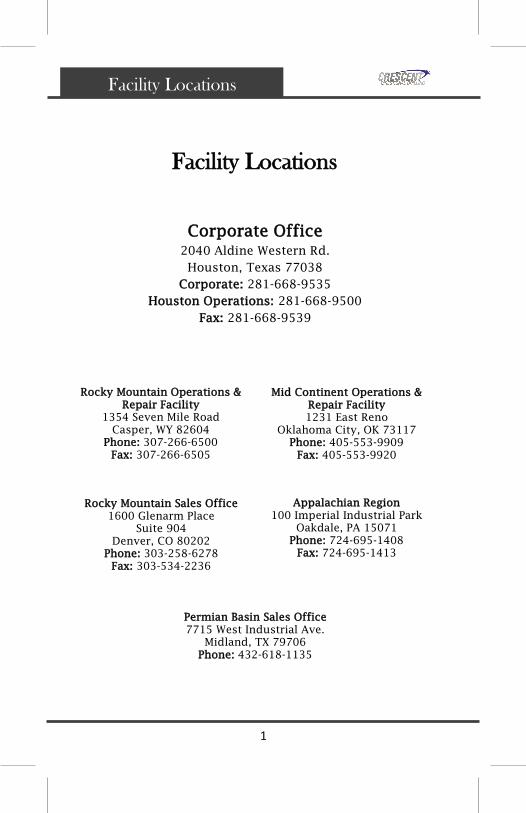
Facility Locations
Corporate Office
2040 Aldine Western Rd.
Houston, Texas 77038
Corporate: 281-668-9535
Houston Operations: 281-668-9500
Fax: 281-668-9539
Facility Locations
Rocky Mountain Sales Office
1600 Glenarm Place
Suite 904
Denver, CO 80202
Phone: 303-258-6278
Fax: 303-534-2236
Rocky Mountain Operations &
Repair Facility
1354 Seven Mile Road
Casper, WY 82604
Phone: 307-266-6500
Fax: 307-266-6505
Mid Continent Operations &
Repair Facility
1231 East Reno
Oklahoma City, OK 73117
Phone: 405-553-9909
Fax: 405-553-9920
Appalachian Region
100 Imperial Industrial Park
Oakdale, PA 15071
Phone: 724-695-1408
Fax: 724-695-1413
Permian Basin Sales Office
7715 West Industrial Ave.
Midland, TX 79706
Phone: 432-618-1135

2
Foreward
Foreward
TAKING YOU IN NEW DIRECTIONS
Crescent Directional Drilling, is a leader in
Directional Drilling - a complex process of drilling
non-vertical wells to increase energy production,
decrease hazardous situations and reduce
environmental impact.
Founded in 2003, the Company has extensive
experience, with its management boasting an average
of 25 years of experience - many with even more.
That expertise also extends to its staff of
coordinators and planners - all with significant
knowledge.
Crescent is a customer-focused, employee-friendly
and technically-advanced company. Known to many
as the "World's best Directional Drilling company,"
Crescent Directional Drilling prides itself on
customer attentiveness, its focus on their employees
and its industry-leading position.
CORE IDEOLOGY
We exist to serve our customers. All else is
secondary. We will accomplish this by fielding the
industry's best Directional Drillers and MWD/EM-
MWD engineers armed with a commitment to go the
extra mile to insure our customer's success in a safe
manner. In addition, office support will be like
minded and employ state of the art technology. An
emphasis on quality will permeate our organization
and the industry's best fit for purpose equipment
will be utilized on all jobs.

3
Conventional Directional Drilling on Land
or Offshore
Extended Reach Wells
3-D Directional Wells
Horizontal Directional Drilling
Casing Jet-in
Jetting / Nudging
Multi-well Platform Drilling
Deepwater Directional Drilling
Cased and Open Hole Sidetracks
Wellbore Correction
Directional Drilling for Underbalanced
Applications
Straight Hole Performance Motor Drilling
Having the proper tools and equipment to
accomplish the job in a quick, efficient and
safe manner is paramount to Crescent
Directional Drilling. We offer our clients a
large selection of in-house products and tools,
each assembled and packaged to meet and
exceed the unique needs of the directional
drilling.
Crescent Directional Drilling Services
Drilling Services

4
Health, Safety, & Environment
Health, Safety, & Environment
Crescent Directional Drilling understands the
importance of providing a safe, accident-free and
healthy work environment. Everyone at Crescent
Directional Drilling takes an active role in safety
and accident avoidance by diligent work and
careful attention to all company policies.
The prevention of occupationally induced injuries
and illnesses is of such significance that we give
it precedence over operating productivity
whenever necessary—no questions asked. Our
safety and accident avoidance programs helped
establish a foundation on which Crescent
Directional Drilling was built—protecting our
greatest assets to ensure our future success.
Crescent Directional Drilling’s primary goal is to
serve our customers by providing the industry’s
best Directional Drillers and MWD/EM-MWD
Engineers to ensure our customer’s success.

5
Crescent Adjustable Motor Instructions
Motor Adjustment
CRESCENT ABH ADJUSTMENT PROCEDURE *ADJUST FROM 0° to 1°

6
Tomahawk Adjustable Motor Instructions
Motor Adjustment

7
Motor Operation
All Crescent motors are sent to the job site with connections
torqued and adjustable housings set to desired angle requested.
Thread protectors are installed on the bit box and top sub. The
motor serial number will be stamped on the bit box of each motor.
Crescent motors can be configured to operate in various conditions
including hot hole, oil based and caustic drilling fluids. The motor
should be visually inspected upon arrival at the rig site for any
damages that may have occurred during shipping and also to make
sure the motor is configured properly.
Thrust bearing wear can be determined by hanging the motor above
the rig floor and taking a measurement between the bit box and the
bottom of the motor bearing housing. Record the measurement.
Then set the bit box on the rig floor allowing the weight of the
motor to compress the bearings, take a measurement from the same
point and subtract from the previous measurement. The difference
between these two measurements should be as follows:
.167” (max.) for 4 3/4” motors
.217” (max.) for 6 1/2” & 6 3/4” motors
.295” (max.) for 8” motors
.333” (max.) for 9 5/8” motors
**Replace the motor if the maximum measurement is exceeded**
A shallow test is recommended to insure proper operation of the
motor and MWD tool. It is also recommended to run a float on top of
the motor to prevent damage to the motor. Some Crescent motors
incorporate a top sub bored for a float, otherwise a float sub will be
provided. When tripping in the hole, it is recommended to break
circulation periodically especially if heat is a factor. Pressure
readings should be recorded for reference later if any problems
should occur.
To start the motor, avoid dropping or ‘spudding’ the motor on the
bottom of the hole. Start circulating a few feet off bottom and raise
the flow rate to recommendations of the particular motor. Apply
weight gradually to achieve optimum differential pressure. Do not
exceed specified maximum differential pressure. The motor may
stall if the power demand exceeds the output of the motor. If the
motor stalls while sliding, immediately shut off the pumps, pull the
motor off bottom, and restart. If the motor stalls while rotating,
shut down the pumps and rotary immediately, pull off bottom, and
then restart. Prolonged stalling will damage the power section. When
the motor run is completed, drain the motor and reinstall thread
protectors.
Motor Operation Procedure

8
FLOW DIVERTER
END NUT & LOWER
INNER RADIAL SLEEVE
BALL BEARING STACKUP
BEARING MANDREL
UPPER INNER & OUTER
RADIAL SLEEVE
TRANSMISSION
ROTOR & STATOR
ROTOR CATCH TOP SUB
CATCH RING
Motor Diagram
FIXED BEND HOUSING

9
Effects of Downhole Temperature
The strength of the elastic liner in the stator diminishes
as the static downhole temperature increases. With an
increase in the downhole temperature, the maximum
recommended pressure drop across the power section
should be adjusted accordingly to avoid premature
deterioration of the stator elastomer.
No adjustment is needed for temperatures up to 140°F.
However, with temperatures above 140°F, the maximum
differential pressure (from the power section charts)
must be multiplied by the ∆P Reduction Factor that
corresponds to the downhole temperature being
experienced by the motor.
Example:
For a maximum recommended differential pressure of
500 psi and a static downhole temperature of 160°F:
∆P Reduction Factor = 87%
500 psi * .87 = 435 psi
As can be seen above, the maximum recommended
differential pressure for this example is 435 psi.
Pressure Reduction Factor

10
Pressure Reduction Factor
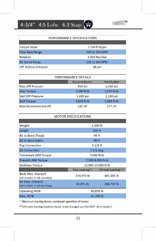
11
4-3/4” 4:5 Lobe 6.3 Stage

12
4-3/4” 4:5 Lobe 6.3 Stage

13
4-3/4” 5:6 Lobe 8.3 Stage

14
4-3/4” 5:6 Lobe 8.3 Stage

15
4-3/4” 7:8 Lobe 2.6 Stage

16
4-3/4” 7:8 Lobe 2.6 Stage

17
4-3/4” 7:8 Lobe 3.8 Stage

18
4-3/4” 7:8 Lobe 3.8 Stage

19
4-3/4” 7:8 Lobe 5.0 Stage

20
4-3/4” 7:8 Lobe 5.0 Stage

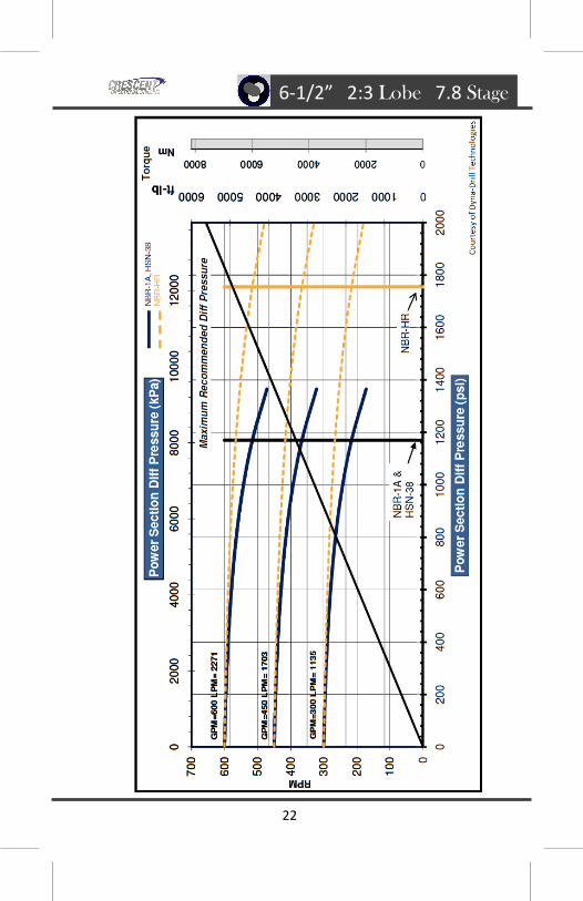
21
6-1/2” 2:3 Lobe 7.8 Stage
22
6-1/2” 2:3 Lobe 7.8 Stage

23
6-1/2” 4:5 Lobe 7.0 Stage

24
6-1/2” 4:5 Lobe 7.0 Stage

25
6-1/2” 7:8 Lobe 2.1 Stage

26
6-1/2” 7:8 Lobe 2.1 Stage

27
6-1/2” SLOW 7:8 Lobe 3.0 Stage

28
6-1/2” SLOW 7:8 Lobe 3.0 Stage

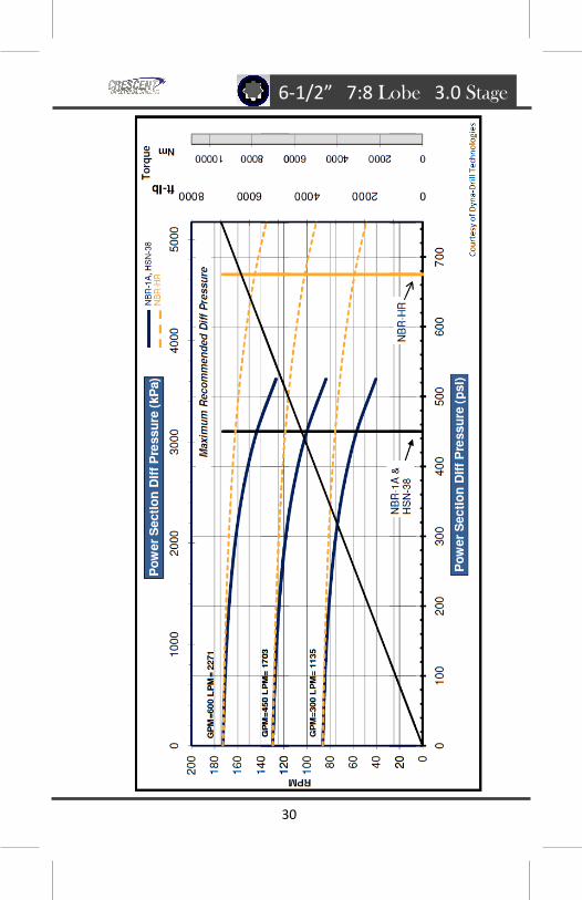
29
6-1/2” 7:8 Lobe 3.0 Stage
30
6-1/2” 7:8 Lobe 3.0 Stage

31
6-1/2” 7:8 Lobe 5.0 Stage

32
6-1/2” 7:8 Lobe 5.0 Stage
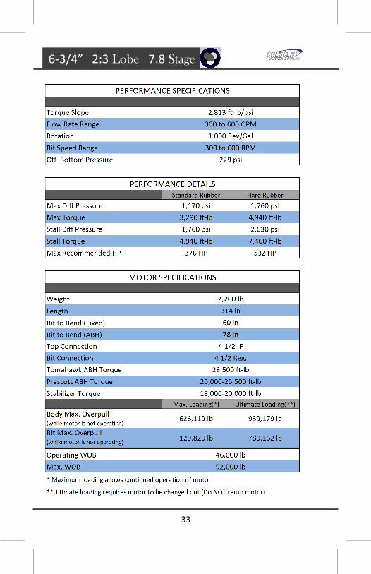
33
6-3/4” 2:3 Lobe 7.8 Stage
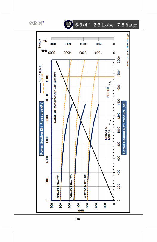
34
6-3/4” 2:3 Lobe 7.8 Stage

35
6-3/4” 4:5 Lobe 7.0 Stage

36
6-3/4” 4:5 Lobe 7.0 Stage

37
6-3/4” 7:8 Lobe 2.1 Stage

38
6-3/4” 7:8 Lobe 2.1 Stage

39
6-3/4” SLOW 7:8 Lobe 3.0 Stage

40
6-3/4” SLOW 7:8 Lobe 3.0 Stage
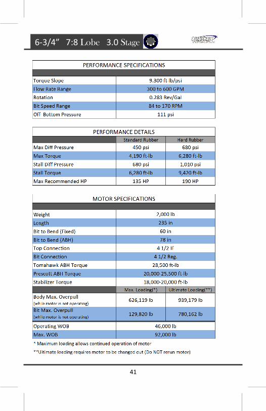
41
6-3/4” 7:8 Lobe 3.0 Stage

42
6-3/4” 7:8 Lobe 3.0 Stage

43
6-3/4” 7:8 Lobe 5.0 Stage

44
6-3/4” 7:8 Lobe 5.0 Stage

45
8” 7:8 Lobe 3.4 Stage

46
8” 7:8 Lobe 3.4 Stage

47
8” 7:8 Lobe 4.0 Stage

48
8” 7:8 Lobe 4.0 Stage

49
9-5/8” 5:6 Lobe 4.0 Stage

50
9-5/8” 5:6 Lobe 4.0 Stage

51
LCM Tolerances M
WD
LC
M T
ole
ran
ces
No
te:
Th
e to
lera
nce
s sh
ow
n a
bo
ve a
re f
or
info
rma
tio
n p
urp
ose
s o
nly
an
d a
re n
ot
gu
ara
nte
ed.

52
MWD Measurements

53
Magnetic Spacing Chart
No
te:
Mo
re t
ha
n o
ne
dri
ll co
llar
is n
eed
ed a
bo
ve t
he
sen
sor
wh
en in
th
e re
gio
n b
elo
w a
nd
to
th
e ri
gh
t o
f th
e re
d c
urv
e.

54
Formulas
Horse Power
T = Torque (lb-ft)
N = Speed (rpm)
P = Pressure Drop (psi)
Q = Flow Rate (gpm)
Pressure
Total Flow Area
P = Pressure Drop (psi)
Q = Flow Rate (gpm)
W = Mud Weight (ppg)
A = Total Flow Area (in2)
Bit Pressure Drop
Hydrostatic D = Vertical Depth (ft)
W = Mud Weight (ppg)
P = Bit Pressure Drop (psi)
Q = Flow Rate (gpm)
W = Mud Weight (ppg)

55
Fishing Dimensions
56
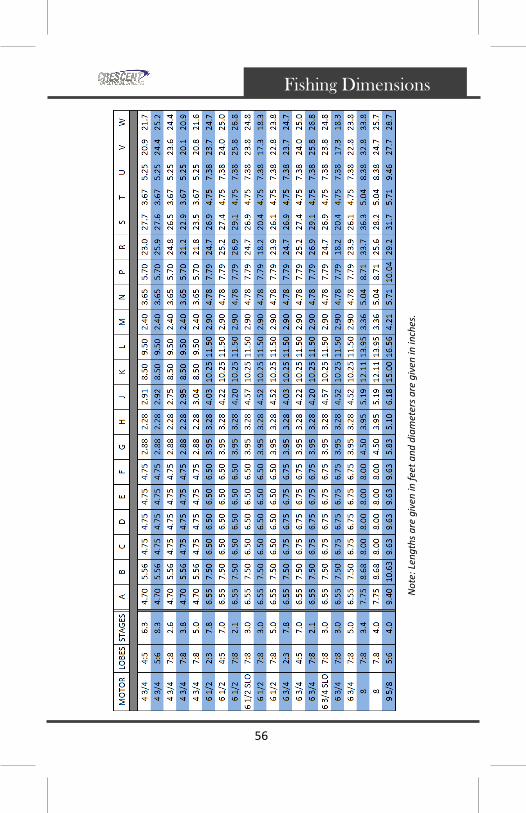
Fishing Dimensions
No
te: L
eng
ths
are
giv
en in
fee
t a
nd
dia
met
ers
are
giv
en in
inch
es.

57
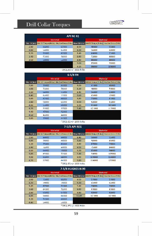
API Drill Collar Torques
Note: Pick the closest value for ID and OD, pick material type,
and use the lowest torque of the values (pin/box).
Drill Collar Torques

58
Drill Collar Torques
59
Drill Collar Torques

60
Reco
mm
en
ded
Bit
Make-u
p T
orq
ues
Bit Make-Up Torques

61
Directional Radius of Curvature
Radius of Curvature

62
Total Flow Area Chart

63
Bouyancy Factor
Bouyancy Factor

64
Float Valve Dimensions
Float Valve Dimensions

65
Heavy-Weight Drill Pipe
Heavy-Weight Drill Pipe

66
Drill Collar Weight
Drill Collar Weight
Linear weight of steel drill collars (lbs/ft)

67
No
te:
Ro
tati
ng
Cre
scen
t M
oto
rs w
ith
ben
d a
ng
les
mo
re t
ha
n 2
deg
rees
is n
ot
reco
mm
end
ed.
Max Drillstring Rotary Speed

68
Build Up Rate Formula
Radius of Curvature =
Build Rate =
Note: Lengths must be in feet.
Build Up Rate
(Three Point Geometry)

69
4 3/4” Build Up Rates
No
te:
Bu
ild r
ate
s g
iven
are
th
eore
tica
l an
d w
ill v
ary
dep
end
ing
on
fo
rma
tio
n, b
it t
ype,
bo
tto
m h
ole
ass
emb
ly, w
eig
ht
on
bit
, a
nd
ho
le c
ha
ract
eris
tics
.

70
6 1/2” Build Up Rates
No
te:
Bu
ild r
ate
s g
iven
are
th
eore
tica
l an
d w
ill v
ary
dep
end
ing
on
fo
rma
tio
n, b
it t
ype,
bo
tto
m h
ole
ass
emb
ly, w
eig
ht
on
bit
, a
nd
ho
le c
ha
ract
eris
tics
.

71
6 3/4” Build Up Rates
No
te:
Bu
ild r
ate
s g
iven
are
th
eore
tica
l an
d w
ill v
ary
dep
end
ing
on
fo
rma
tio
n, b
it t
ype,
bo
tto
m h
ole
ass
emb
ly, w
eig
ht
on
bit
, a
nd
ho
le c
ha
ract
eris
tics
.

72
8” Build Up Rates
No
te:
Bu
ild r
ate
s g
iven
are
th
eore
tica
l an
d w
ill v
ary
dep
end
ing
on
fo
rma
tio
n, b
it t
ype,
bo
tto
m h
ole
ass
emb
ly, w
eig
ht
on
bit
, a
nd
ho
le c
ha
ract
eris
tics
.

73
9 5/8” Build Up Rates
No
te:
Bu
ild r
ate
s g
iven
are
th
eore
tica
l an
d w
ill v
ary
dep
end
ing
on
fo
rma
tio
n, b
it t
ype,
bo
tto
m h
ole
ass
emb
ly, w
eig
ht
on
bit
, a
nd
ho
le c
ha
ract
eris
tics
.

www.crescentdirectional.com
Corporate Office
2040 Aldine Western Rd.
Houston, Texas 77038
Corporate: 281-668-9535
Houston Operations: 281-668-9500
Fax: 281-668-9539
Rocky Mountain Sales Office
1600 Glenarm Place
Suite 904
Denver, CO 80202
Phone: 303-258-6278
Fax: 303-534-2236
Rocky Mountain Operations &
Repair Facility
1354 Seven Mile Road
Casper, WY 82604
Phone: 307-266-6500
Fax: 307-266-6505
Mid Continent Operations &
Repair Facility
1231 East Reno
Oklahoma City, OK 73117
Phone: 405-553-9909
Fax: 405-553-9920
Appalachian Region
100 Imperial Industrial Park
Oakdale, PA 15071
Phone: 724-695-1408
Fax: 724-695-1413
Permian Basin Sales Office
7715 West Industrial Ave.
Midland, TX 79706
Phone: 432-618-1135