moose tower project report - university of colorado denver ... · moose tower lidar scanning...
TRANSCRIPT

1
Moose Tower LIDAR Scanning Project Report
CoPR – Center of Preservation Research College of Architecture and Planning
University of Colorado Denver
1512 Larimer Street, Suite 750, Denver, CO 80202 p 303.315.5871 f 303.315.5872
August 30, 2012
Project Team:
Ekaterini Vlahos Associate Professor of Architecture & Planning Director, Center of Preservation Research
Michael Nulty
Documentation Coordinator
Julia Ausloos
Research Assistant
Contents:
1. Site Evaluation and Assessment 2. Data Gathering and General Site Procedures
o Site Photos 3. Data Management
o Processing Images 4. Data Archiving 5. Data Representation 6. Field Notes
2
1. Site Evaluation and Assessment:
Description of Site: Moose Tower is an impressive free standing structure with a number of associated structures and infrastructure surrounding including several granaries and a reservoir. The tower is composed of three rooms set on top of a large boulder several meters from the cliff edge as well as another 3 story tower next to the boulder. The construction of the tower is a compound masonry with some grout still remaining. The organic nature of the architecture makes traditional documentation methods such as hand measuring very difficult. LiDAR scanning is a powerful tool for this particular site as the tower and surounding context is so complex and non‐linear.
2. Data Gathering and General Site Procedures
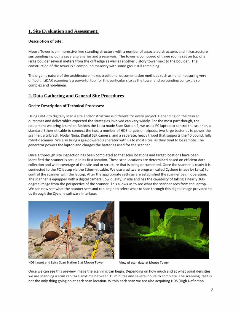
Onsite Description of Technical Processes: Using LiDAR to digitally scan a site and/or structure is different for every project. Depending on the desired outcomes and deliverables expected the strategies involved can vary widely. For the most part though, the equipment we bring is similar. Besides the Leica made Scan Station 2, we use a PC laptop to control the scanner, a standard Ethernet cable to connect the two, a number of HDS targets on tripods, two large batteries to power the scanner, a tribrach, Nodal Ninja, Digital SLR camera, and a separate, heavy tripod that supports the 40 pound, fully robotic scanner. We also bring a gas‐powered generator with us to most sites, as they tend to be remote. The generator powers the laptop and charges the batteries used for the scanner. Once a thorough site inspection has been completed so that scan locations and target locations have been identified the scanner is set up in its first location. These scan locations are determined based on efficient data collection and wide coverage of the site and or structure that is being documented. Once the scanner is ready it is connected to the PC laptop via the Ethernet cable. We use a software program called Cyclone (made by Leica) to control the scanner with the laptop. After the appropriate settings are established the scanner begin operation. The scanner is equipped with a digital camera (low quality) inside and has the capability of taking a nearly 360‐degree image from the perspective of the scanner. This allows us to see what the scanner sees from the laptop. We can now see what the scanner sees and can begin to select what to scan through this digital image provided to us through the Cyclone software interface.
Once we can see this preview image the scanning can begin. Depending on how much and at what point densities we are scanning a scan can take anytime between 15 minutes and several hours to complete. The scanning itself is not the only thing going on at each scan location. Within each scan we are also acquiring HDS (High Definition
HDS target and Leica Scan Station 2 at Moose Tower View of scan data at Moose Tower

3
Group photo from Left to Right: Julia Ausloos, Mike Nulty, Neffra Mathews Tom Noble and Vince MacMillan. With SS2 running in the background
Surveying) targets. These are very precise points in space that allow us to tell the scanner where it was in space in relationship to the other scan locations. This is important for post‐processing efforts once data collection is complete. The process telling the computer where each scan location was in relation to the other scan locations is called registration. This is when we tie all the scans together to create a completed 3D model.
Once scanning and target acquisition is completed we use the Digital SLR camera to collect better image information than the scanner can. We take the time to collect HDR (High Dynamic Range) photography at each location. HDR allows us to capture high quality images that give us more information than standard photography. We also collect RAW images for greatest quality and color range. We collect a 365‐degree sphere of images that we later stitch together and texture map onto the point cloud data for a more photo‐realistic 3D model. Once scanning and HDR photograph is complete at each location the process of moving to the next location must be completed. During the process of moving all the equipment related to the scanning process it is critical to make sure that they stay out of the way of the scans. We often are shifting around the generator, battery boxes, scanner boxes, etc. to ensure we are only capturing the site and its structures. As we move equipment around we are also being very cautious not to shift targets. These HDS targets are so accurate that even an accidental touch can shift the target out of position giving you errors in the post‐processing effort. The target locations are also very specific so they can be seen from multiple scan locations. At each location the scanner is disconnected, powered down and moved with care.

4
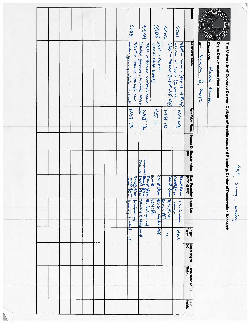
Procedures and Scanning Effort Details:
The University of Colorado Denver scanned Moose Tower and surrounding context using a Leica Scan
Station 2 Scanner from Tuesday, August 7th through August 9th 2012. Two CoPR employees, Julia
Ausloos and Mike Nulty, arrived at the Moose Tower site in the mornings along with Vince MacMillan,
Neffra Mathews and Tom Noble. In total, thirteen different scan locations were acquired on site, and of
those locations seven consisted of 360 degree scans to acquire surrounding context of the site. The
remaining scans consisted of detailed window scans of the tower and other important features. In
addition to scanning, 13 panoramic images were also captured at each location to be used for photo
texturing during post processing. Seven HDS targets were used throughout the site as control points
that would later tie all scan locations together. Five to seven targets were acquired at each location. On
average the 360 degree scan locations took about an hour and a half, while the other window scan
locations took about 45 minutes (please see field notes for a more detailed scan schedule).
The On Site scanning was made more complicated by the fact that a team from the BLM’s NOC was on
site during the same time performing photogrammetry of the same site. The two teams came up with
an initial plan on how best to stay out of each other’s way and maintain an efficient schedule before
meeting on site. Throughout the days there was a lot of communication to confirm where each team
would be and what parts of the site they would be working on.
Both teams documented the survey control for both technologies. For photogrammetry the BLM used
measuring sticks with targets and patterns. The LiDAR team used HDR targets throughout the site.

5
Site Photos
Leica Scan Station 2
Mike Nulty scanning rooms on top of Moose Tower
Team overlooking cliff edge above Moose Tower
Tom Noble with BLM Photogrammetry Team

6
3. Data Management
Initial Post‐Processing:
Towards the middle of August initial post processing of the Moose Tower began. The 13 panoramic
images were processed applied to each scan location making the data look more photo‐realistic. All 13
scan locations were registered together using a combination of target and feature registration with a
Mean Absolute Error (MAE) of only .002 m.
The data will someday be used to produce HABS drawings as part of a future agreement.
Scan Data view of Granary
Scan Data view from above

7
4. Data Archiving:
Archiving strategies used for Moose Tower:
For Moose Tower full copies of raw and processed data will exist in several places and media. UCD will
have a copy of the data backed up on an external hard drive as well as on a local computer. A copy of
the data will eventually be housed on DVDs located in a different geographic location from the hard
drives as extra protection against loss. The data will also be delivered to the BLM for their records. UCD
is not contracted to store or backup the data for any amount of time.
5. Data Representation:
Representation for Moose Tower:
The end goal of this project is to collect the data in such a way that it can be used later to produce HABS
drawings. Main elevations, context and plan information was gathered so that traditional, 2D line
drawings may be produced in the future. One of the strengths of this technology is that it can be mined
for additional visualizations and data for research purposes as well.