monocular vision-based autonomous navigation system on …pingtan/papers/icuas15.pdf · monocular...
TRANSCRIPT

Monocular Vision-Based Autonomous Navigation System on a ToyQuadcopter in Unknown Environments
Rui Huang1, Ping Tan1, Ben M.Chen2
Abstract— In this paper, we present an monocular vision-based autonomous navigation system for a commercial quad-coptor. The quadcoptor communicates with a ground-basedlaptop via wireless connection. The video stream of the frontcamera on the drone and the navigation data measured on-board are sent to the ground station and then processed by avision-based SLAM system. In order to handle motion blur andframe lost in the received video, our SLAM system consists ofa improved robust feature tracking scheme and a relocalisationmodule which achieves fast recovery from tracking failure.An Extended Kalman filter (EKF) is designed for sensorfusion. Thanks to the proposed EKF, accurate 3D positionsand velocities can be estimated as well as the scaling factorof the monocular SLAM. Using a motion capture system withmillimeter-level precision, we also identify the system models ofthe quadcoptor and design the PID controller accordingly. Wedemonstrate that the quadcoptor can navigate along pre-definedpaths in an unknown indoor environment with our system usingits front camera and onboard sensors only after some simplemanual initialization procedures.
I. INTRODUCTION
Autonomous navigation of flying robots has drawn in-creasing attention in recent years. Autonomous unmannedaerial vehicles (UAV) have great potential in military andcivil applications such as surveillance, search and rescue,indoor mapping and 3D reconstruction. Various applicationsof the UAVs have been demonstrated in both indoor andourdoor environments. Kushleyev et al. [1] achieve accurateformation control of twenty micro UAVs that have weightsaround 73 grams using external motion capture system.In the sFly European Project [2], a team of UAVs withdownward facing cameras scan a large outdoor area and builda 3D sparse map collaboratively. Autonomous navigation ofmicro UAVs in GPS-denied unknown environments is still anopen research question. One of the challenges is that microUAVs have limited payload and power supply. Therefore,color cameras are often preferable sensors for the navigationcontrol.
In terms of the autonomous navigation of UAVs usingon-board sensors in GPS-denied indoor environments, L.R.Garcia Carrillo et al. [3] address the road following problemby adopting a downward looking camera for road detectionand tracking. They also design switching controllers forstabilizing the pose of the UAV with respect to the road.As the camera is also used as the major sensor in their
1Rui Huang and Ping Tan are with the School of Computing Science,Simon Fraser University, Canada. {rha55, pingtan}@sfu.ca
2Ben M. Chen is with the Department of Electrical andComputer Engineering, National University of Singapore, [email protected]
system, the approach is limited to the straight line segmentsappeared in the image. Our visual SLAM system is able todeal with more general environments and allows the UAV tofollow arbitrary defined paths. M. Achtelik et al. [4] presenta complete autonomous air vehicle system that is capableof autonomous navigation and exploration in GPS-deniedenvironments. They design a quadrotor platform capableof carrying a laser rangefinder, stereo camera rig, colorcamera, and on-board computer. In contrast, we aim at alightweight approach to autonomous navigation using onlyon-board sensors of a toy quadrotor. Our system can be easilyintegrated with micro UAVs with limited sensing payload.
Visual SLAM techniques use video cameras for simul-taneously localisation and mapping. Klein et al. [5] built asystem called PTAM using a color camera for visual SLAM.Newcombe et al. [6] proposed a dense tracking and mappingsystem which can reconstruct dense surfaces of the sceneusing a single camera. KinectFusion [7] is a accurate real-time SLAM system using a RGB-D camera and commoditygraphics hardware. Compared to color cameras, RGB-Dcameras have larger weight and higher power consumption.Despite these advances in visual SLAM, it is still challengingto use a monocular camera for autonomous navigation ofan UAV. There are two major challenges. Firstly, a microUAV has limited computation power. Thus, a ground stationis often used to carry out the involved computation, witha Wi-Fi link to communicate with the drone. Since noiseand signal loss during data transmission are unavoidablein real flights, the SLAM system must be robust to theseproblems. Secondly, the scaling ambiguity of monocularSLAM needs to be solved so that the results can be fusedwith the measurements from other on-board sensors.
We present an autonomous navigation system for a lowcost toy quadcoptor called AR.Drone. The quadcoptor com-municates with a ground-based laptop via wireless connec-tion. The video stream of the front camera on the droneand the navigation data measured on-board are sent to theground station and then processed by our visual SLAMsystem. In order to handle motion blur and frame loss in thereceived video, our SLAM system consists of an improvedKLT tracker and a relocalisation module which achievesfast recovery from tracking failure. An Extended Kalmanfilter (EKF) is designed for sensor fusion to solve the scaleambiguity in visual SLAM. Our system recovers accurate3D positions and velocities to control the drone with PIDcontrollers. We further evaluate our system performance witha motion capture system with millimeter-level precision. Itis demonstrated that the quadcoptor can navigate along pre-

defined paths in an unknown environment using our system.Similar autonomous navigation system has been developed
in [8] on an AR.Drone. In their system, an extended Kalmanfilter (EKF) is designed to fuse all available measurements.In order to compensate the data transmission latency, dronepose is predicted by a heuristic motion model assuming fixedlatency. However, in practice, we found the data transmissionlatency varies over time. Furthermore, [8] uses a standalonescale estimator to solve the scaling ambiguity. Specifically,given a time interval, both of the visual SLAM and on-board metric sensors estimate the distance traveled by thedrone. Assuming both of the measurements contain Gaussiannoise with constant variance, the scale can be solved by amaximum likelihood approach. This approach to solve thescale ambiguity relies heavily on the drone’s vertical motion,because it requires accurate altitudes from the ultrasonicsensor. However, vertical motion is not common duringindoor navigation. Nutzi et al. [9] present a different methodto solve the scale ambiguity of visual SLAM. They alsodesigned an EKF, where the scale presents in the state spaceand is estimated continuously. The scale is computed bycomparing the position from visual SLAM and the positionfrom integrating IMU measurements. This scale estimationsuffers from drifting errors caused by integration. Motivatedby both of the approaches, we design a novel EKF to fuse thevisual SLAM and velocity measurement from the on-boardsensors. The position estimated by visual SLAM is able tocorrect the position drifting caused by integrating the velocitymeasurements. The velocity measurements in turn providegood reference for the scale estimation. Our EKF fuses bothmeasurements to solve the scale ambiguity and minimizedrifting errors. At the same time, we design our visual SLAMalgorithm to make it robust to data communication errors andlatencies.
The remaining of the paper is organized as following.The platform and software used along with our system isdiscussed in Section 2. Our visual SLAM system is runningon a ground-based laptop. We adopts the idea from PTAMto separate the mapping and tracking process for betterefficiency. To achieve better robustness to data transmissionproblems, we enhance the feature tracking and include are-localization component. The details of our visual SLAMsystem are discussed in Section 3. As described by Bristeauet al. [10], the AR.Drone estimates the linear velocities inthe horizontal plane of the body frame with its on-boardsensors. These velocities are estimated by a navigation filterintegrating the measurements of a downward looking cameraand inertial sensors. We take these on-board measurementsand fuse them with the results of our visual SLAM systemusing a novel Extended Kalman filter which is elaborated inSection 4. Section 5 presents experiment evaluations. Thevideos demonstrating the autonomous path following areavailable online:http://www.sfu.ca/˜rha55/.
II. PLATFORM
The AR.Drone is a micro Unmanned Aerial Vehicle (UAV)developed by the Parrot company for the increasing market
Front Camera
Electronic Assistance including a vertical camera, ultrasound sensor, 3 axis gyroscope, 3 axis accelerometer and ARM A8 processor.
Fig. 1. The Parrot AR.Drone 2.0.
of videos games and home entertainment. The drone is low-cost, safe, and easy to fly by end users. These properties alsomake it a suitable platform for our research.
A. Hardware
The AR.Drone platform is detailed in [10]. We brieflysummarize it here to make this work self-contained. Thedrone is based on a classic quadrotor design with four brush-less motors. The on-board electronics consists of two boards,i.e., Mother-board and Navigation board. The mother-boardis equipped with an ARM9-core processor running at 468MHz. A Linux based operating system and all on-boardcomputations are run on the processor. The mother-boardis connected to two cameras including a front camera anda downward-looking camera. The front camera has a viewangle of 93 degrees and a VGA resolution of 640 × 480.It can capture at up to 30 Hz. The vertical camera is a 64degrees diagonal lens camera used to perform the estimationof the vehicle speed. The navigation board is equipped withthe sensors including a 3-axis accelerometers, a 2-aixs gyro-scope, a 1-axis vertical gyroscope and 2 ultrosonic sensors.The ultrasonic sensors provide the altitude estimation andthe vertical displacements of the UAV. The embedded oper-ating system manages the Wi-Fi communications betweenthe UAV and the ground station. It is also in charge ofvideo sampling and compression, image processing, sensorsacquisition, state estimation and closed-loop control. Oncea computer is connected to the broadcasting Wi-Fi network,the Wi-Fi chip can transmit sensor data and estimated statesat 200Hz, and compressed video frames at up to 30Hz. Theimportant components of the AR.Drone is highlighted inFigure 1.
B. Platform Modeling and Controller Design
The attitude stabilization of the drone is performed on-board and realized by the attitude control loop and theangular rate control loop [10]. The attitude reference is setby sending floating number parameters between [−1, 1] tothe four channels including roll angle, pitch angle, verticalspeed, and yaw rate.

+
-
F G1s
PIDX /Y X /Ye u Pitch / Roll Angle VelocityX /Y
Fig. 2. Control loop for X and Y positions.
+
-H
1s
PIDψ/ ZYaw rate / Z velocityψ/Z e u
Fig. 3. Control loop for yaw angle ψ and altitude Z.
In order to design the outer loop controllers, we need toperform system modeling for the on-board controllers. Thecontrol loop for X,Y positions is illustrated in Figure 2.The control loop for vertical altitude and yaw angle isshown in Figure 3. We use the System Identification Toolboxof MATLAB to fit the system transfer functions for eachchannel separately. Firstly, we sample a sequence of achirp signal as the control parameters. Then we send thecontrol signals at the sampling rate to the drone and recordthe response using a motion capture system called Viconwith millimeter precision. The input control signals of rollangle and corresponding roll measurements are plotted inFigure 4. The input and output signals are then processedby the System Identification Toolbox to generate the transferfunctions.
In Figure 2, the PID controller receives position error ein the local North-East-Down (NED) frame of the drone andcomputes control signal u. The transfer function F describesthe relation of control signal u and roll or pitch angles. Thenthe velocity along X or Y − axis can be predicted by G.By integrating the velocity, the predicted position can beobtained. Figure 3 shows the control loop applied to yawangle and altitude control. The control signal u encodesthe desired yaw rate or vertical velocity. Thus, the transferfunction H estimates the yaw rate and vertical velocity basedon the control signals. The identified transfer functions are
0 100 200 300 400 500−0.5
0
0.5
Time (Second)
Con
trol
Sig
nal
0 100 200 300 400 500−0.5
0
0.5
Time (Second)
Ang
le (
Rad
ian)
Fig. 4. Input control parameters and roll angle measurements by Vicon.
listed as following.
Fx =0.76034
0.0247s2 + 0.3144s+ 1, Gx =
−15.945
1.6583s+ 1(1)
Fy =0.74113
0.0215s2 + 0.2935s+ 1, Gy =
10.130
1.0569s+ 1(2)
Halt =0.879
0.0619s2 + 0.2608s+ 1(3)
Hyaw =1.5203
0.0359s+ 1(4)
With the identified system models, we solve our PIDcontrollers with the filter coefficient parameter N using theSimulink software of MATLAB. The discrete PID controllerin our implementation is presented below. The control signalut is generated at 25 Hz based on the position or angle erroret. the sampling time ∆t = 1
25 seconds. The reference statexref consists of the drone’s 3D position and its yaw angle.
ut = Pt + It +Dt (5)
Pt = et ·Kp (6)
It =
∫et∆t ·Ki (7)
Dt =Dt−1 +Kd ·N · (et − et−1)
1 +N ·∆t(8)
et = xref − xt (9)
The gains of the PID controllers used in our implemen-tation are presented in Table I. Note that the control gainsof X Position Controller are negative. With the driver weare using to control the ARDrone, positive control signals ofthe pitch angle make the drone move towards the negativeX − axis. So the error in X position and the control signalhave opposite signs.
TABLE IPARAMETERS OF OUR PID CONTROLLERS
Controller Kp Kd K i NX Position Controller -0.144 -0.267 -6.362e-6 203.645Y Position Controller 0.247 0.241 1.595e-5 186.796Yaw Angle Controller 6.564 0 0 0
Altitude Controller 0.600 0.100 0.001 138.861
III. VISUAL SLAM
Our visual SLAM system consists of a highly efficientand robust feature tracking component. The feature tracksare then used to register the current camera position to aglobal 3D map. From time to time, new 3D map points aretriangulated and new key-frames are inserted, to enhance sys-tem robustness. A local Bundle Adjustment (BA) optimizethe global map in a parallel thread. Our SLAM system alsoincludes a re-localisation module, which enables it to recoverfrom tracking failure.

A. Feature Tracking
Our feature tracker detects strong corners [11] and trackthem by a sparse iterative version of the Lucas-Kanade opti-cal flow [12]. To facilitate exploration of new environments,it detects new corners every five frames. A feature track willbe terminated whenever its correspondence cannot be found.The drone’s motion could cause blurry frames, especially inrelatively dark indoor environments where longer exposureis required. Blurry frames leads to rapid and significantdrop in the number of tracked corners, and hence poorcamera pose estimation. A re-localization could address thisproblem, while it is relatively computationaly expensive. Weobserve most of the blurs last only a few frames (≤ 3), sowe design a ‘rollback’ scheme for the tracker to deal withfrequent and short blurs. If the number of tracked cornersdrops significantly at the k-th frame, we try to track fromthe frames in [k − 5, k − 1] to the frames in [k + 1, k + 3].If it succeed, re-localization will not be called.
This rollback scheme cannot solve all tracking problems.Sometimes, multiple continuous video frames could be lostdue to poor Wi-Fi connection. When this happens, none ofthe previously visited frames can be tracked to the currentframe. Such an example is provided in Figure 7, where thetwo received consecutive frames have quite a large motion. Inthis case, our system will activate the re-localization moduleto recover from the tracking failure. Specifically, we countthe number of feature tracks with 3D information in thecurrent frame. If the percentage of these feature tracks dropsbelow a threshold, the re-localisation will be triggered. Thedetails of our re-localisation method is in section III-D.
B. Camera Pose Estimation
The camera intrinsics are pre-calibrated and fixed. Wesolve the camera extrinsics Θ = (R, t) by minimizing thefollowing reprojection error,
Θopt = arg minΘ
∑i
ρ(||mi − P(Mi,Θ)||), (10)
where P(Mi,Θ) projects a 3D map point M to the imageplane and m is its corresponding image feature. The functionρ is the Tukey bi-weight function [13]. We minimize Equa-tion 10 by the iteratively re-weighted least squares (IRLS)method. The Θ is initialized as the camera pose at theprevious frame. At each iteration of the IRLS, the Levenberg-Marquart algorithm is used to solve the non-linear leastsquare problem.
C. Keyframe Insertion and Map Generation
The current frame will be inserted as a keyframe if itsatisfies the following criteria. Firstly, it is separated fromthe last keyframe for a certain interval. Secondly, the numberof tracked 3D map points in it is below a threshold. Further-more, the number of unmapped feature tracks are more thana threshold. We cache a keyframe as the full size image, a
downsized thumbnail image, and its tracked corners and theircorresponding 3D map points.
New map points will be generated when the tracking isstable while the number of tracked map points is dropping.We evaluate the stability of tracking by the ratio of thenumber of tracked corners in the current frames and thatnumber in the previous frame. If this ratio is higher thana threshold, we consider the tracking is stable. New mappoints are triangulated [14] using the feature points at thehead and tail of feature tracks. The triangulated map pointsare accepted only if their reprojection errors are smaller thana threshold, they are not behind of any cameras, and thetriangulation angle between the two cameras is larger than athreshold.
D. Relocalisation
Re-localization is critical for the system robustness. Dur-ing re-localisation, each available input frame will be down-sized and compared with the cached thumbnails of thekeyframes. We set the width of the thumbnails to be 100and the threshold of the sum of squared difference (SSD)between two thumbnails to be 100. If a similar keyframeK is successfully found for the input frame F , the currentcamera position will then be registered to the global map viathe keyframe K. In this way, the SLAM system can recoverfrom tracking failures.
To register K and F , we search feature matching betweenthem. In order to obtain high quality matching within rea-sonable processing time, we firstly detect FAST features [15]in F and K. We then compute the SIFT descriptors [16] atthese features and match them within a local neighborhoodwith diameter of 6 pixels. Then the two sets of descriptorsare matched using the FLANN matcher [17]. Although thealgorithm is designed to produce high quality feature match-ing, there are still outliers in the output feature matches. Wefurther eliminate the outliers by fitting the essential matrixwith RANSAC alorithm [14].
In order to boost the number of feature matchings, we de-tect additional correspondences by masking the existing ones.These new features and their corresponds will be triangulatedto generate additional 3D map points. The triangulated 3Dpoint is valid if its reprojection errors are smaller than3 pixels. Otherwise, it is discarded and the correspondingfeature match is considered as an outlier. Empirically, wefind this step is important, since it ensures sufficient featureswith 3D information when the system is recovered. Withoutit, the system is likely fail again soon and re-localization willbe triggered repetitively. The pipeline of our vision systemis illustrated in Figure 5
IV. SENSOR FUSION
The results of visual SLAM are up to a scale. Thisscaling ambiguity must be solved so that the reconstructed3D information can be used for navigation control. On theother hand, the on-board sensors of an AR.Drone estimatethe drone’s altitude and its velocities on the horizontalplane. In principal, we could obtain the drone’s position by

New frameavailable?
FeatureTracking
Enough mappedTracks?
Camera poseestimation
Is the estimated
posevalid?
Add new keyframe
Finish processing one frame
Map generation
Re-localisation
New frame available
Register the new frame
To the global map
Is the registrationsuccessful?
No
No
No
No
Yes
Yes
Yes
Yes
Fig. 5. SLAM system pipeline
integrating its horizontal velocities over time. However, suchan integration suffers from bad drifting errors. We describea sensor fusion algorithm based on extended Kalman filterto fuse the results from visual SLAM and the outputs fromonboard sensors.
While Engel et al.[8] also employed EKF for sensorfusion and scale estimation, our solution has the followingadvantages. Firstly, we use a much simplified state spaceto reduce the computation, thanks for the good accuracyof the on-board attitude and velocity measures. Secondly,unlike [8], our scale estimator does not rely much on verticalmotion of the drone, which is not common in the real flights.Our proposed EFK is inspired by Nutzi et al. [9], wherethe scale is estimated by comparing the results of visualSLAM and integration of IMU measurements. To address thedrifting errors in integrating IMU measurements, we solvethe scale factor by comparing velocities from visual SLAMand onboard sensors.
A. Our EKF
In this section, we introduce the state space of the EKFfollowed by the prediction model and the measurementmodel. We empirically found the attitude returned from thedrone’s onboard sensor is quite robust. So the state spaceonly consists of the position p in meter, velocity p in meterper second and scaling factor s in meter. These are the only
inputs to our controller for generating control commands.The state space is:
x =
pps
. (11)
This state space involves the one-dimensional position p andvelocity p for the sake of simplicity. However, it is easy tobe extended to multiple dimensions.
The prediction model is:
xk|k−1 = f(xk−1,uk−1) + wk−1 (12)
There is no u, since we do not have an input control. Thisprediction model can be further expressed as the following,
xk|k−1 =
1 ∆t 00 1 00 0 1
· xk−1 + G · ak−1 (13)
and
G =
∆t2/2∆t0
(14)
In this constant acceleration model, we assume the accelera-tion a of the drone is constant during ∆t and follows a zero-mean normal distribution with standard deviation. Therefore,the covariance Q of the state transition noise w can becomputed as the following,
Q = GGTσa2 (15)
The state transition matrix is defined by,
F =
1 ∆t 00 1 00 0 1
(16)
and the predicted estimate covariance is obtained by,
Pk|k−1 = FkPk−1|k−1FkT + Qk. (17)
The measurement model considers two measurementsources, i.e., visual tracking and onboard sensors. We obtainthe estimated position directly from the visual SLAM system.To compute the velocity at time t measured by the visualSLAM system, we differentiate the positions pt and pt′ atframes Nt and Nt′ . The time stamps t and t′ are recordedwith the video frames. The frame difference ∆N is set to30 in our experiments to avoid sudden jump in velocityestimation.
The first measurement model for the position pv andvelocity pv from the visual SLAM system is,
zv = h(xv) + vv (18)
where
h(xv) =
[1/s 0 00 1/s 0
]· xv, (19)
zv =
[pvpv
], (20)

t 1Second
Fig. 6. Measurement update scheme
and vv is the observation noise of the visual tracking. Thusthe observation matrix is
Hv =
[1/s 0 −s−2 · p0 1/s −s−2 · p
](21)
The second measurement model for the estimated velocitypn from the navigation data is,
zn = h(xn) + vn (22)
whereh(xn) =
[0 1 0
]· xn, (23)
zn = pn, (24)
and vn is the observation noise of the navigation dataobtained from the onboard sensors. Thus the observationmatrix is
Hn =[0 1 0
]. (25)
Once there is a new measurement from either visualtracking or onboard sensors, the EKF will be updated. Theinnovation residual and covariance are,
yk = zk − h(xk|k−1) (26)
Sk = HkPk|k−1HkT + Rk (27)
The Kalman gain is computed as,
Kk = Pk|k−1HkTSk
−1 (28)
Finally, the state x and covariance P are updated by,
xk = xk|k−1 + Kkyk (29)
andPk|k = (I−KkHk)Pk|k−1 (30)
respectively.
B. Filter Update Scheme
We now consider the update scheme of different mea-surements. The AR.Drone transmits the navigation data andvideo frames to the ground station for processing. Both datatransmission and processing cause latency. We then propose ameasurement update scheme for compensating these delays.
The navigation data including the estimated velocity arebuffered in a queue once received. The EKF will only beupdated permanently when a measurement from the visualtracking is ready. The updates are based on the time stampwhen the data are received from the drone. Then we use thebuffered navigation data to predict the states to the currenttime.
As illustrated in Figure 6, red arrows represent the up-dates of the EKF using available measurements from visual
Frame 508 Frame 509
Fig. 7. The video is discontinuous at frame 508 and 509 due to the frameloss caused by unstable Wi-Fi link
Our Result PTAM
Fig. 8. The left figure shows our results of camera position reconstruction.The relocalisation algorithm is activated in the period highlighted by theorange rectangle. The right figures shows the failed result of PTAM.
tracking at t1, t2. The blue arrows in between represent theupdates of the EKF using the buffered measurements fromnavigation data. To obtain a better estimation of the currentstates before the next visual measurement is available, weonly use the buffered navigation data received after t2 todo the prediction as shown by yellow arrows. The state ofthe EKF will be updated up to time t3 which is closest tothe current time. The latest measurement used for update isshown in the green arrow.
V. EXPERIMENTS
Our visual SLAM system can achieve real-time perfor-mance and the control signal is generated at 25 Hz on theground station and sent to the drone. We first evaluate theindividual SLAM and EKF components respectively. Then,the whole system is tested in real flights and the ground truthpositions measured by the Vicon system are examined. Theexperiment environment is shown in Figure 14.
A. SLAM system
Our system is robust to feature tracking failures whichcan happen due to multiple reasons, including blurry framesand frame loss in transmission. A typical example of frameloss is shown in Figure 7, where two received consecutiveframes have significant change to make feature tracking fail.Our system is robust to these kinds of problems, owing to the‘rollback’ scheme in tracking and the re-localization module.
We show a comparison with the well known monocularSLAM system PTAM [5] on the videos recorded by ourAR.Drone. Figure 8 shows the reconstructed camera trajec-tories from both systems. In this example, the drone is facinga table and moves surround it and then back to the startingpoint. Our system can successfully reconstruct the cameratrajectory for the whole sequence. Note that the position

Frame 508 Frame 509
Fig. 9. Snapshots of tracking from PTAM
Frame 508 Frame 509 Frame 517
Fig. 10. Snapshots of tracking from our system
jumps as highlighted by the orange rectangle in the left ofFigure 8. This sudden change in position is due to the frameloss. Our method can deal with this type of problems better.
Empirically, we find our feature tracking is superior thanthat in PTAM. PTAM’s feature tracker adopts a motion modelto predict the feature’s location in the coming video frame.It only search correspondences nearby the predicted featurelocation. In practice, we find this pre-defined motion modelis often inconsistent with the drone’s motion. Thus, thetrue feature is significantly different in orientation and scalewith the predicted one. This problem makes PTAM’s featuretracking fragile. As presented in Figure 9, the sudden viewchange causes a significant drop in the number of trackedfeatures for PTAM. The estimated plane and the pose areobviously wrong. In comparison, our method is free fromthis problem. As shown in Figure 10, we indicate the trackedfeature points with corresponding 3D map points in green. Asudden viewpoint change will cause significant drop in thenumber of green points (see the middle of Figure 10). Oncethat happens, our relocalisation will be triggered to revivethe system (see the right of Figure 10).
Figure 11 shows another challenging example, where thecamera makes a quick turn at a corner. As the scene changesquickly during the navigation, it is difficult for a visualSLAM system to register map points to image features.Our system tracks feature well and detect new featureswhenever the number of tracked feature drops significantly.Furthermore, our map points triangulation is not limited tothe keyframes. New map points can be generated timelyand added to the map. This makes the system robust toscene occlusion and large view change. Figure 12 showsthe comparison of the results generated by our system andPTAM. It is clear that our system also tracked more featurepoints than PTAM as shown in Figure 13.
B. EKF based Sensor Fusion and Scale Estimation
We evaluate our proposed extended Kalman filter in thissection. Our EKF directly provides the position estimationof the drone in real metric unit. The scaling ambiguity ofthe visual SLAM results is solved as a state in the filter. We
Fig. 11. Camera moving around a corner formed by two planes withtextures
Our Result PTAM
Fig. 12. The left figure shows our results of camera position reconstruction.The right figures shows the result of PTAM. PTAM failed when the camerais turning at the corner
compare the estimated positions with Vicon measurementsto have quantitative evaluation for our approach. This resultis shown in Figure 15. In this flight, the drone is mainlynavigating along the Y − axis. We register the Viconcoordinate system to the one used in our visual SLAM,so that the Vicon measurements can be transformed to theNorth-East-Down (NED) frame of the drone. The blue curvesshows the Vicon measurements of position in Y − axis andour estimated positions are in red. Our estimated positionsmatch the Vicon measurement closely. For a comparison, wealso plot the positions computed by directly integrating theonboard velocity measurement. It is clearly shown that theintegration suffers from large drifting errors.
Figure 16 shows the state space of the EKF along Y−axis.The third row presents the estimation of scaling factor.Although the initial state is far from the correct scale, thefilter can converge in less than 15 seconds. The initializa-tion process can be done manually before the autonomousnavigation starts.
Our Result PTAM
Fig. 13. During the navigation, our system (Left) tracked more featuresthan PTAM (Right).

Fig. 14. The experiments are performed in an unknown environment. Thetextures pasted in the environment are only used to boost the features in theoriginal environment with poor textures.
0 10 20 30 40 50 60 70−500
0
500
1000
1500
2000
2500
3000
Time (Second)
Pos
ition
(m
m)
Vicon MeasurementsIntegrated PositionsFiltered Positions
Fig. 15. The blue curves shows the Vicon measurements of position inY −axis and our estimated positions are in red. The integrated position ingreen shows a large drifting error.
0 10 20 30 40 50 60−1000
0100020003000
Second
Pos
ition
(m
m)
0 10 20 30 40 50 60 70−1000
0
1000
Second
Vel
ocity
(m
m/s
)
0 10 20 30 40 50 60 700
2000
4000
SecondSca
ling
Fac
tor
(mm
)
Fig. 16. The state space of the EKF
−1000
−500
0
500
1000
−1000
−500
0
500
10000
500
1000
1500
2000
X Position (mm)Y Position (mm)
Z P
ositi
on (
mm
)
Fig. 17. 3D position of the UAV measured by Vicon system in the hoveringtest
0 10 20 30 40 50 60 70−500
0
500
Time (Second)
X P
ositi
on (
mm
)0 10 20 30 40 50 60 70
−500
0
500
Time (Second)Y
Pos
ition
(m
m)
0 10 20 30 40 50 60 701000
1100
1200
Time (Second)
Z P
ositi
on (
mm
)
Fig. 18. 2D plot of the hovering test result. The UAV position measuredby the Vicon system is shown in blue and the set point is denoted by thered line.
C. Complete System Performance
We firstly verify our system with a hovering test in anunknown indoor environment. After initializing the visualSLAM system manually, we sent the hovering command tothe AR.Drone. The drone then tries to hold to the referenceposition using the estimated pose. Meanwhile, we use the Vi-con system to record the precise positions of the flying drone.The root-mean-square-error (RMSE) of the drone’s positionis computed for quantitative evaluation. In this hovering test,the RMSE of the position errors are 70.1821mm in X−axis,86.51mm in Y −axis, and 16.75mm in Z−axis. The erroris smaller in the Z−axis because our EKF module fuses thealtitude measure of the ultrasonic sensor. Figure 17 shows theposition of the UAV in 3D space. Figure 18 demonstrates thepositions measured by Vicon system (blue) and the referencepositions (red) along individual axis.
We further carry out path following experiments to makethe drone autonomously follow a pre-defined 3D path. Theinput path is generated with a sequence of set-points withreference positions and velocities. We adopted a similarapproach used in [18] and [19] to generate the reference tra-jectory with continuous and limited velocity and acceleration.
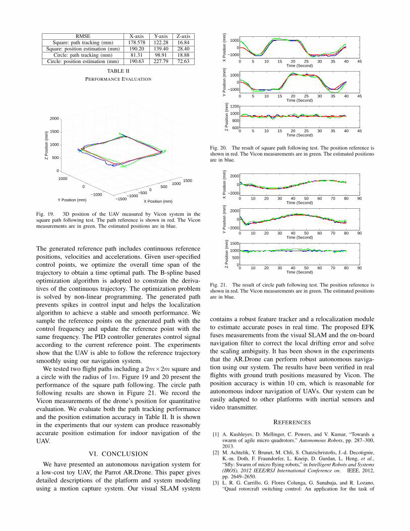
RMSE X-axis Y-axis Z-axisSquare: path tracking (mm) 178.578 122.28 16.84
Square: position estimation (mm) 190.20 139.40 28.40Circle: path tracking (mm) 81.31 98.91 18.88
Circle: position estimation (mm) 190.63 227.79 72.63
TABLE IIPERFORMANCE EVALUATION
−1500−1000
−5000
5001000
1500
−1000
0
1000
0
500
1000
1500
2000
X Position (mm)Y Position (mm)
Z P
ositi
on (
mm
)
Fig. 19. 3D position of the UAV measured by Vicon system in thesquare path following test. The path reference is shown in red. The Viconmeasurements are in green. The estimated positions are in blue.
The generated reference path includes continuous referencepositions, velocities and accelerations. Given user-specifiedcontrol points, we optimize the overall time span of thetrajectory to obtain a time optimal path. The B-spline basedoptimization algorithm is adopted to constrain the deriva-tives of the continuous trajectory. The optimization problemis solved by non-linear programming. The generated pathprevents spikes in control input and helps the localizationalgorithm to achieve a stable and smooth performance. Wesample the reference points on the generated path with thecontrol frequency and update the reference point with thesame frequency. The PID controller generates control signalaccording to the current reference point. The experimentsshow that the UAV is able to follow the reference trajectorysmoothly using our navigation system.
We tested two flight paths including a 2m×2m square anda circle with the radius of 1m. Figure 19 and 20 present theperformance of the square path following. The circle pathfollowing results are shown in Figure 21. We record theVicon measurements of the drone’s position for quantitativeevaluation. We evaluate both the path tracking performanceand the position estimation accuracy in Table II. It is shownin the experiments that our system can produce reasonablyaccurate position estimation for indoor navigation of theUAV.
VI. CONCLUSION
We have presented an autonomous navigation system fora low-cost toy UAV, the Parrot AR.Drone. This paper givesdetailed descriptions of the platform and system modelingusing a motion capture system. Our visual SLAM system
0 5 10 15 20 25 30 35 40 45
−1000
0
1000
Time (Second)
X P
ositi
on (
mm
)
0 5 10 15 20 25 30 35 40 45
−1000
0
1000
Time (Second)
Y P
ositi
on (
mm
)
0 5 10 15 20 25 30 35 40 45600
800
1000
1200
Time (Second)
Z P
ositi
on (
mm
)
Fig. 20. The result of square path following test. The position reference isshown in red. The Vicon measurements are in green. The estimated positionsare in blue.
0 10 20 30 40 50 60 70 80 90−2000
0
2000
Time (Second)
X P
ositi
on (
mm
)
0 10 20 30 40 50 60 70 80 90−2000
0
2000
Time (Second)
Y P
ositi
on (
mm
)
0 10 20 30 40 50 60 70 80 900
500
1000
1500
Time (Second)
Z P
ositi
on (
mm
)
Fig. 21. The result of circle path following test. The position reference isshown in red. The Vicon measurements are in green. The estimated positionsare in blue.
contains a robust feature tracker and a relocalization moduleto estimate accurate poses in real time. The proposed EFKfuses measurements from the visual SLAM and the on-boardnavigation filter to correct the local drifting error and solvethe scaling ambiguity. It has been shown in the experimentsthat the AR.Drone can perform robust autonomous naviga-tion using our system. The results have been verified in realflights with ground truth positions measured by Vicon. Theposition accuracy is within 10 cm, which is reasonable forautonomous indoor navigation of UAVs. Our system can beeasily adapted to other platforms with inertial sensors andvideo transmitter.
REFERENCES
[1] A. Kushleyev, D. Mellinger, C. Powers, and V. Kumar, “Towards aswarm of agile micro quadrotors.” Autonomous Robots, pp. 287–300,2013.
[2] M. Achtelik, Y. Brunet, M. Chli, S. Chatzichristofis, J.-d. Decotignie,K.-m. Doth, F. Fraundorfer, L. Kneip, D. Gurdan, L. Heng, et al.,“Sfly: Swarm of micro flying robots,” in Intelligent Robots and Systems(IROS), 2012 IEEE/RSJ International Conference on. IEEE, 2012,pp. 2649–2650.
[3] L. R. G. Carrillo, G. Flores Colunga, G. Sanahuja, and R. Lozano,“Quad rotorcraft switching control: An application for the task of

path following,” Control Systems Technology, IEEE Transactions on,vol. 22, no. 4, pp. 1255–1267, 2014.
[4] M. Achtelik, A. Bachrach, R. He, S. Prentice, and N. Roy, “Au-tonomous navigation and exploration of a quadrotor helicopter in gps-denied indoor environments,” in First Symposium on Indoor Flight,no. 2009, 2009.
[5] G. Klein and D. Murray, “Parallel tracking and mapping for small arworkspaces,” in Mixed and Augmented Reality, 2007. ISMAR 2007.6th IEEE and ACM International Symposium on. IEEE, 2007, pp.225–234.
[6] R. A. Newcombe, S. J. Lovegrove, and A. J. Davison, “Dtam: Densetracking and mapping in real-time,” in Computer Vision (ICCV), 2011IEEE International Conference on. IEEE, 2011, pp. 2320–2327.
[7] R. A. Newcombe, A. J. Davison, S. Izadi, P. Kohli, O. Hilliges,J. Shotton, D. Molyneaux, S. Hodges, D. Kim, and A. Fitzgibbon,“Kinectfusion: Real-time dense surface mapping and tracking,” inMixed and augmented reality (ISMAR), 2011 10th IEEE internationalsymposium on. IEEE, 2011, pp. 127–136.
[8] J. Engel, J. Sturm, and D. Cremers, “Camera-based navigation ofa low-cost quadrocopter,” in Intelligent Robots and Systems (IROS),2012 IEEE/RSJ International Conference on. IEEE, 2012, pp. 2815–2821.
[9] G. Nutzi, S. Weiss, D. Scaramuzza, and R. Siegwart, “Fusion of imuand vision for absolute scale estimation in monocular slam,” Journalof intelligent & robotic systems, vol. 61, no. 1-4, pp. 287–299, 2011.
[10] P.-J. Bristeau, F. Callou, D. Vissiere, N. Petit, et al., “The navigationand control technology inside the ar. drone micro uav,” in 18th IFACworld congress, vol. 18, no. 1, 2011, pp. 1477–1484.
[11] J. Shi and C. Tomasi, “Good features to track,” in Computer Visionand Pattern Recognition, 1994. Proceedings CVPR’94., 1994 IEEEComputer Society Conference on. IEEE, 1994, pp. 593–600.
[12] J.-Y. Bouguet, “Pyramidal implementation of the affine lucas kanadefeature tracker description of the algorithm,” Intel Corporation, vol. 5,2001.
[13] Z. Zhang, “Parameter estimation techniques: A tutorial with applica-tion to conic fitting,” Image and vision Computing, vol. 15, no. 1, pp.59–76, 1997.
[14] R. Hartley and A. Zisserman, Multiple view geometry in computervision. Cambridge university press, 2003.
[15] E. Rosten and T. Drummond, “Machine learning for high-speed cornerdetection,” in Computer Vision–ECCV 2006. Springer, 2006, pp. 430–443.
[16] D. G. Lowe, “Distinctive image features from scale-invariant key-points,” International journal of computer vision, vol. 60, no. 2, pp.91–110, 2004.
[17] M. Muja and D. G. Lowe, “Fast approximate nearest neighbors withautomatic algorithm configuration.” in VISAPP (1), 2009, pp. 331–340.
[18] K. Li, R. Huang, S. K. Phang, S. Lai, F. Wang, P. Tan, B. M.Chen, and T. H. Lee, “Off-board visual odometry and control ofan ultralight quadrotor mav,” in IMAV 2014: International Micro AirVehicle Conference and Competition 2014, Delft, The Netherlands,August 12-15, 2014. Delft University of Technology, 2014.
[19] S. K. Phang, S. Lai, F. Wang, M. Lan, and B. M. Chen, “Uav cal-ligraphy,” in Control & Automation (ICCA), 11th IEEE InternationalConference on. IEEE, 2014, pp. 422–428.