monochrome camera function chart 3
TRANSCRIPT
www.pro.sony.eu/vision
We make cameras do things you wouldn’t believe
Last update: October 2010
2010Machine Vision Product Catalogue
Intelligent Cameras
Digital Interface – IEEE1394b-2002
Digital Interface – Camera Link
Digital Interface – GigE Vision
Non-TV Format
TV Format
3-CCD Colour Video Cameras
IMAGE SENSING SOLUTIONS
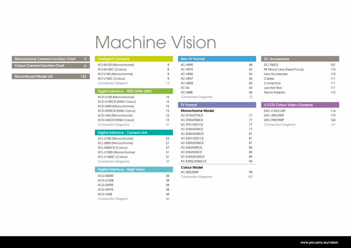
Monochrome Camera Function Chart 3
Colour Camera Function Chart 6
Discontinued Model List 132
Intelligent Cameras
XCI-SX100 (Monochrome) 8
XCI-SX100C (Colour) 8
XCI-V100 (Monochrome) 8
XCI-V100C (Colour) 8
Connection Diagram 13
Digital Interface - IEEE1394b-2002
XCD-U100 (Monochrome) 15
XCD-U100CR (RAW Colour) 15
XCD-SX90 (Monochrome) 15
XCD-SX90CR (RAW Colour) 15
XCD-V60 (Monochrome) 15
XCD-V60CR (RAW Colour) 15
Connection Diagrams 21
Digital Interface - Camera Link
XCL-U100 (Monochrome) 23
XCL-5005 (Monochrome) 27
XCL-5005CR (Colour) 27
XCL-U1000 (Monochrome) 31
XCL-U1000C (Colour) 31
Connection Diagrams 35
Digital Interface - GigE Vision
XCG-5005E 38
XCG-U100E 38
XCG-SX99E 38
XCG-SX97E 38
XCG-V60E 38
Connection Diagram 46
Non-TV Format
XC-HR90 48
XC-HR70 52
XC-HR50 56
XC-HR57 56
XC-HR58 60
XC-56 64
XC-56BB 68
Connection Diagrams 72
TV Format
Monochrome Model XC-ST70/ST70CE 77
XC-ST50/ST50CE 77
XC-ST51/ST51CE 77
XC-ST30/ST30CE 77
XC-ES50/ES50CE 81
XC-ES51/ES51CE 81
XC-ES30/ES30CE 81
XC-EI50/EI50CE 85
XC-EI30/EI30CE 85
XC-EU50/EU50CE 89
XC-ES50L/ES50LCE 94
Colour Model XC-505/505P 98
Connection Diagrams 102
XC Accessories
DC-700CE 107
NF Mount Lens (Fixed Focus) 110
Lens Accessories 110
Cables 111
Connectors 111
Junction Box 111
Tripod Adaptor 112
3-CCD Colour Video Cameras
DXC-C33/C33P 114
DXC-390/390P 119
DXC-990/990P 124
Connection Diagrams 131
Machine Vision
www.pro.sony.eu/vision
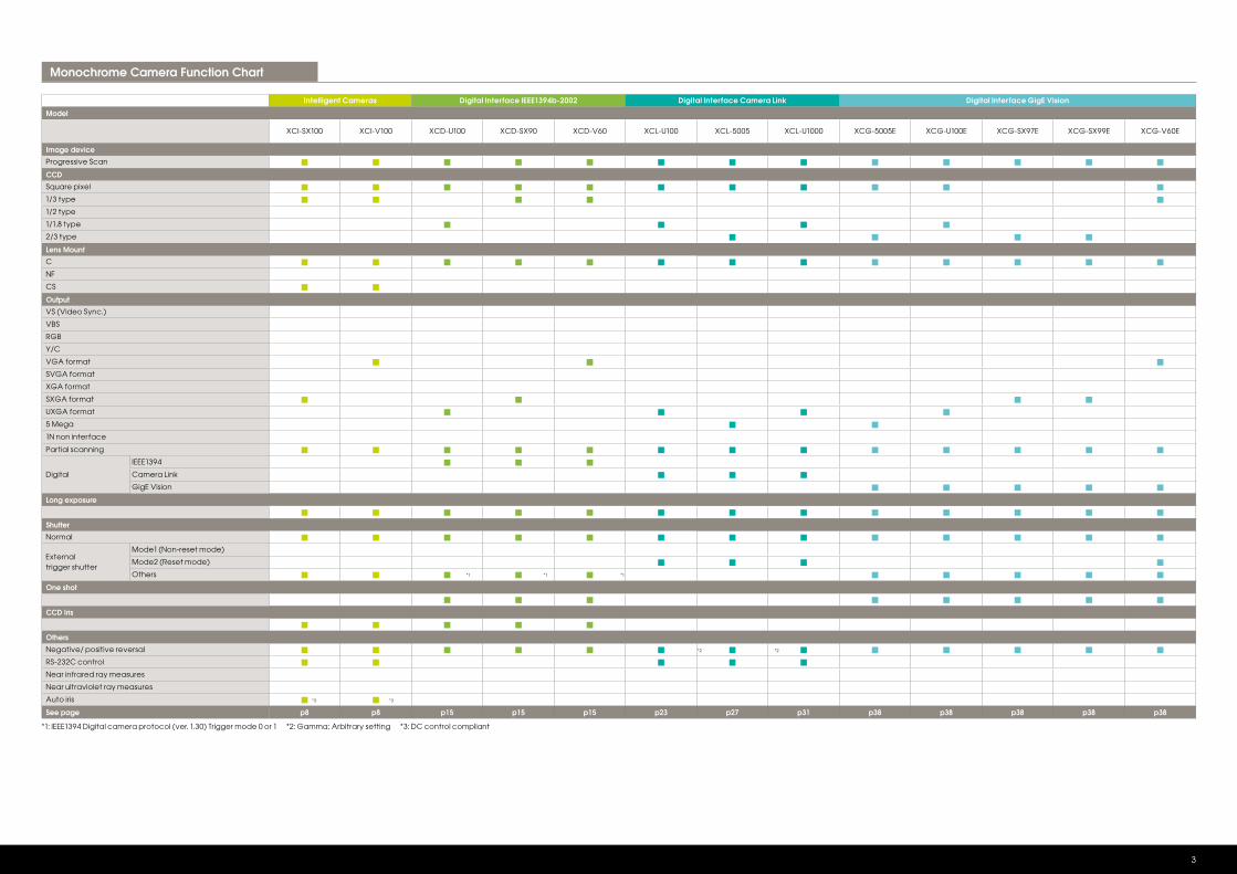
Monochrome Camera Function Chart
3
Intelligent Cameras Digital Interface IEEE1394b-2002 Digital Interface Camera Link Digital Interface GigE Vision
Model
XCI-SX100 XCI-V100 XCD-U100 XCD-SX90 XCD-V60 XCL-U100 XCL-5005 XCL-U1000 XCG-5005E XCG-U100E XCG-SX97E XCG-SX99E XCG-V60E
Image device
Progressive Scan
CCD
Square pixel
1/3 type
1/2 type
1/1.8 type
2/3 type
Lens Mount
C
NF
CS
Output
VS (Video Sync.)
VBS
RGB
Y/C
VGA format
SVGA format
XGA format
SXGA format
UXGA format
5 Mega
1N non interface
Partial scanning
Digital
IEEE1394
Camera Link
GigE Vision
Long exposure
Shutter
Normal
External trigger shutter
Mode1 (Non-reset mode)
Mode2 (Reset mode)
Others
One shot
CCD Iris
Others
Negative/ positive reversal
RS-232C control
Near infrared ray measures
Near ultraviolet ray measures
Auto iris
See page p8 p8 p15 p15 p15 p23 p27 p31 p38 p38 p38 p38 p38
*1: IEEE1394 Digital camera protocol (ver. 1.30) Trigger mode 0 or 1 *2: Gamma; Arbitrary setting *3: DC control compliant
*3 *3
*2 *2
*1 *1 *1
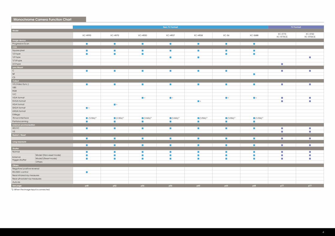
Non-TV Format TV Format
Model
XC-HR90 XC-HR70 XC-HR50 XC-HR57 XC-HR58 XC-56 XC-56BBXC-ST70
XC-ST70CEXC-ST50
XC-ST50CE
Image device
Progressive Scan
CCD
Square pixel
1/3 type
1/2 type
1/1.8 type
2/3 type
Lens Mount
C
NF
CS
Output
VS (Video Sync.)
VBS
RGB
Y/C
VGA format
SVGA format
XGA format
SXGA format
UXGA format
5 Mega
1N non interface
Partial scanning
External synchronization
HD/VC
VS
Restart / Reset
Long exposure
Shutter
Normal
External trigger shutter
Mode1 (Non-reset mode)
Mode2 (Reset mode)
Others
Others
Negative/ positive reversal
RS-232C control
Near infrared ray measures
Near ultraviolet ray measures
Auto iris
See page p48 p52 p56 p56 p60 p64 p68 p77 p77
*2: When the image input is connected
Monochrome Camera Function Chart
4
*2
*2
*2 *2
*2
*2 *2
(1/30s)*2 (1/30s)*2 (1/30s)*2 (1/30s)*2(1/60s)*2 (1/60s)*2 (1/50s)*2
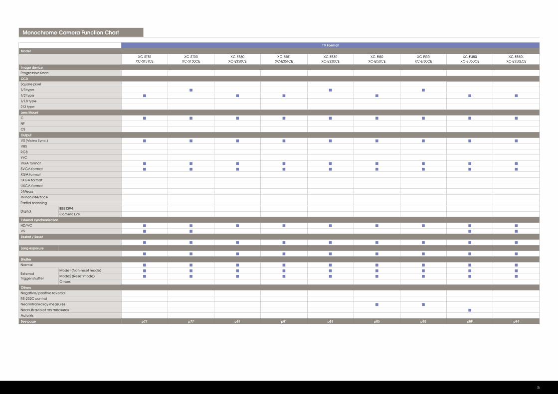
TV Format
Model
XC-ST51XC-ST51CE
XC-ST30XC-ST30CE
XC-ES50XC-ES50CE
XC-ES51XC-ES51CE
XC-ES30XC-ES30CE
XC-EI50XC-EI50CE
XC-EI30XC-EI30CE
XC-EU50XC-EU50CE
XC-ES50LXC-ES50LCE
Image device
Progressive Scan
CCD
Square pixel
1/3 type
1/2 type
1/1.8 type
2/3 type
Lens Mount
C
NF
CS
Output
VS (Video Sync.)
VBS
RGB
Y/C
VGA format
SVGA format
XGA format
SXGA format
UXGA format
5 Mega
1N non interface
Partial scanning
DigitalIEEE1394
Camera Link
External synchronization
HD/VC
VS
Restart / Reset
Long exposure
Shutter
Normal
External trigger shutter
Mode1 (Non-reset mode)
Mode2 (Reset mode)
Others
Others
Negative/ positive reversal
RS-232C control
Near infrared ray measures
Near ultraviolet ray measures
Auto iris
See page p77 p77 p81 p81 p81 p85 p85 p89 p94
Monochrome Camera Function Chart
5
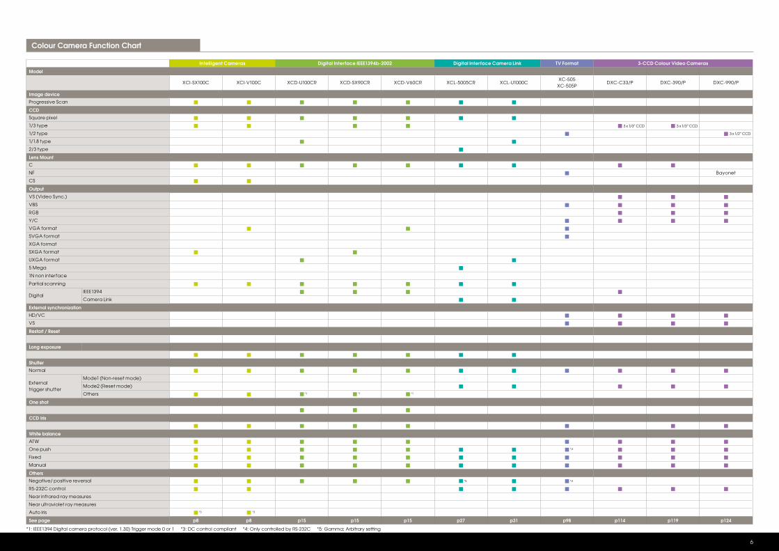
Intelligent Cameras Digital Interface IEEE1394b-2002 Digital Interface Camera Link TV Format 3-CCD Colour Video Cameras
Model
XCI-SX100C XCI-V100C XCD-U100CR XCD-SX90CR XCD-V60CR XCL-5005CR XCL-U1000CXC-505
XC-505PDXC-C33/P DXC-390/P DXC-990/P
Image device
Progressive Scan
CCD
Square pixel
1/3 type
1/2 type
1/1.8 type
2/3 type
Lens Mount
C
NF Bayonet
CS
Output
VS (Video Sync.)
VBS
RGB
Y/C
VGA format
SVGA format
XGA format
SXGA format
UXGA format
5 Mega
1N non interface
Partial scanning
DigitalIEEE1394
Camera Link
External synchronization
HD/VC
VS
Restart / Reset
Long exposure
Shutter
Normal
External trigger shutter
Mode1 (Non-reset mode)
Mode2 (Reset mode)
Others
One shot
CCD Iris
White balance
ATW
One push
Fixed
Manual
Others
Negative/ positive reversal
RS-232C control
Near infrared ray measures
Near ultraviolet ray measures
Auto iris
See page p8 p8 p15 p15 p15 p27 p31 p98 p114 p119 p124
*1: IEEE1394 Digital camera protocol (ver. 1.30) Trigger mode 0 or 1 *3: DC control compliant *4: Only controlled by RS-232C *5: Gamma; Arbitrary setting
Colour Camera Function Chart
6
*1
*3 *3
*5 *4
*4
*1 *1
3 x 1/3” CCD 3 x 1/3” CCD
3 x 1/2” CCD
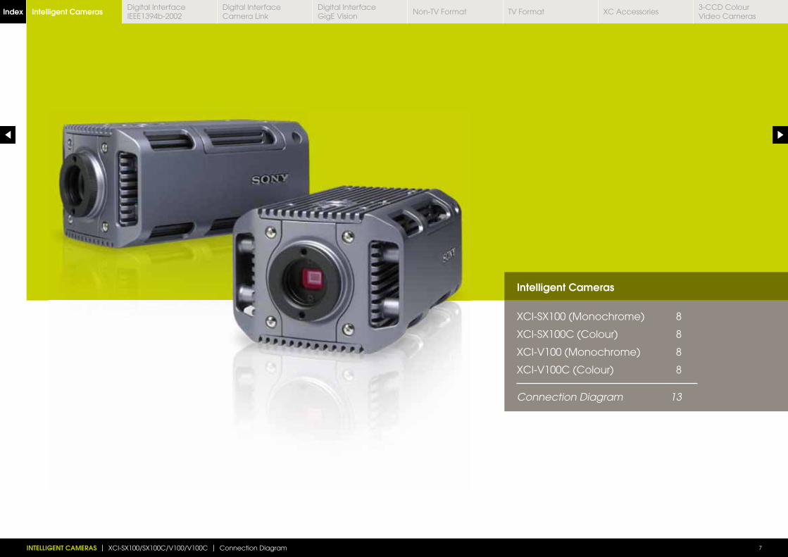
Intelligent Cameras
XCI-SX100 (Monochrome) 8
XCI-SX100C (Colour) 8
XCI-V100 (Monochrome) 8
XCI-V100C (Colour) 8
Connection Diagram 13
INTELLIGENT CAMERAS | XCI-SX100/SX100C/V100/V100C | Connection Diagram 7
Intelligent CamerasIndex Digital Interface IEEE1394b-2002
Digital Interface Camera Link
Digital InterfaceGigE Vision
Non-TV Format TV Format XC Accessories3-CCD Colour Video Cameras
Connection Diagram p13Dimensions (mm)
1
6
XCI-SX100 NEW
XCI-V100 NEW
XCI-SX100C NEW
XCI-V100C NEW
Intelligent Camera ColourIntelligent Camera Monochrome
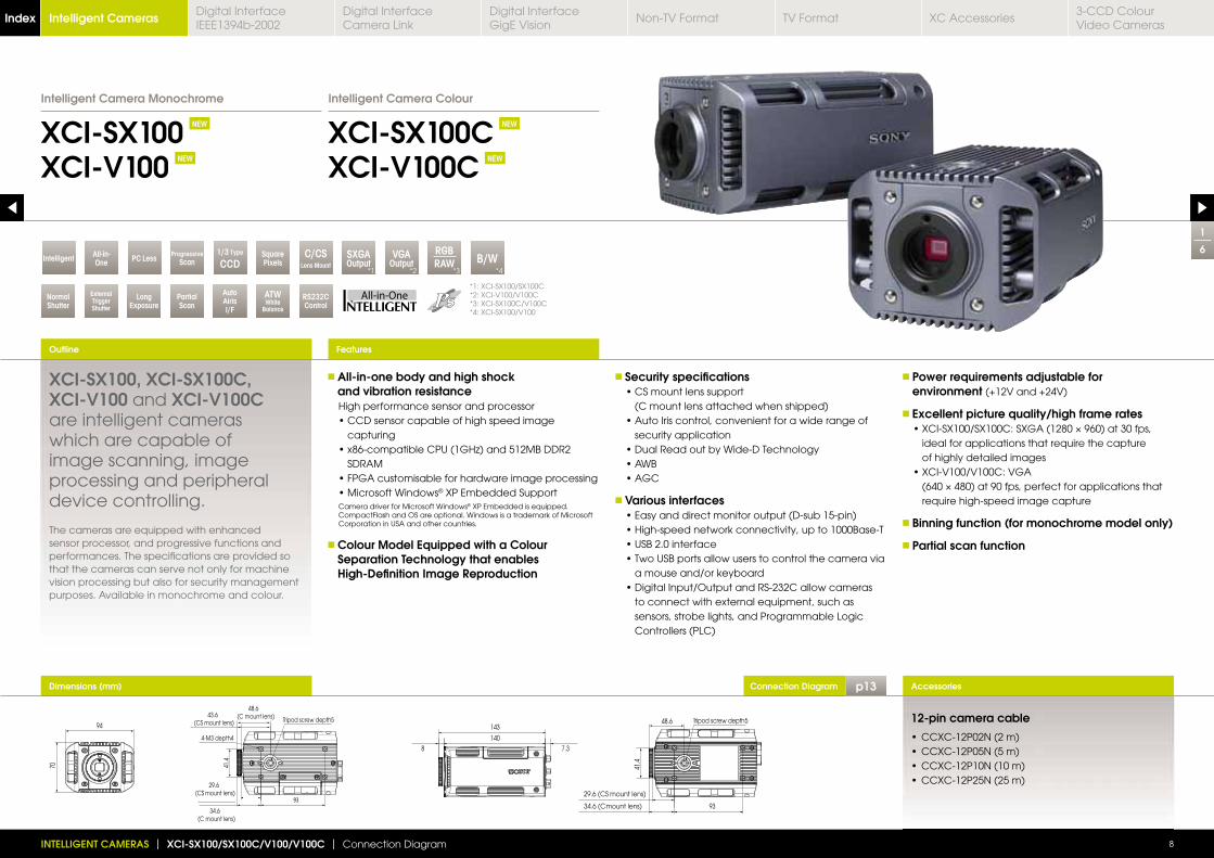
XCI-SX100, XCI-SX100C, XCI-V100 and XCI-V100C are intelligent cameras which are capable of image scanning, image processing and peripheral device controlling.
The cameras are equipped with enhanced sensor processor, and progressive functions and performances. The specifications are provided so that the cameras can serve not only for machine vision processing but also for security management purposes. Available in monochrome and colour.
All-in-one body and high shock and vibration resistance
High performance sensor and processor
capturing
SDRAM
® XP Embedded Support Camera driver for Microsoft Windows® XP Embedded is equipped.
CompactFlash and OS are optional. Windows is a trademark of Microsoft Corporation in USA and other countries.
Colour Model Equipped with a Colour Separation Technology that enables High-Definition Image Reproduction
Security specifications
(C mount lens attached when shipped)
security application
Various interfaces
a mouse and/or keyboard
to connect with external equipment, such as sensors, strobe lights, and Programmable Logic Controllers (PLC)
Power requirements adjustable for environment (+12V and +24V)
Excellent picture quality/high frame rates
ideal for applications that require the capture of highly detailed images
require high-speed image capture
Binning function (for monochrome model only)
Partial scan function
Outline
INTELLIGENT CAMERAS | XCI-SX100/SX100C/V100/V100C | Connection Diagram 8
Accessories
Features
94
70
48.6 (C mount lens)
29.6(CS mount lens)
93
4-M3 depth4
Tripod screw depth543.6
(CS mount lens)
41.4
34.6(C mount lens)
34.6(C mount lens)
140
143
8 7.3
34.6 (C mount lens)
Tripod screw depth5
41.4
48.6
29.6 (CS mount lens)
93
12-pin camera cable
*1: XCI-SX100/SX100C*2: XCI-V100/V100C*3: XCI-SX100C/V100C*4: XCI-SX100/V100
PartialScan
AutoAirisI/F
ATWWhite
Balance
RS232CControl
SXGAOutput
VGAOutput B/W
NormalShutter
ExternalTriggerShutter
LongExposure
RGBRAW
SquarePixels
C/CSLens Mount
1/3 Type
CCDIntelligent*1
All-in-One
*2
PC Less*3
ProgressiveScan
*4
Intelligent CamerasIndex Digital Interface IEEE1394b-2002
Digital Interface Camera Link
Digital InterfaceGigE Vision
Non-TV Format TV Format XC Accessories3-CCD Colour Video Cameras
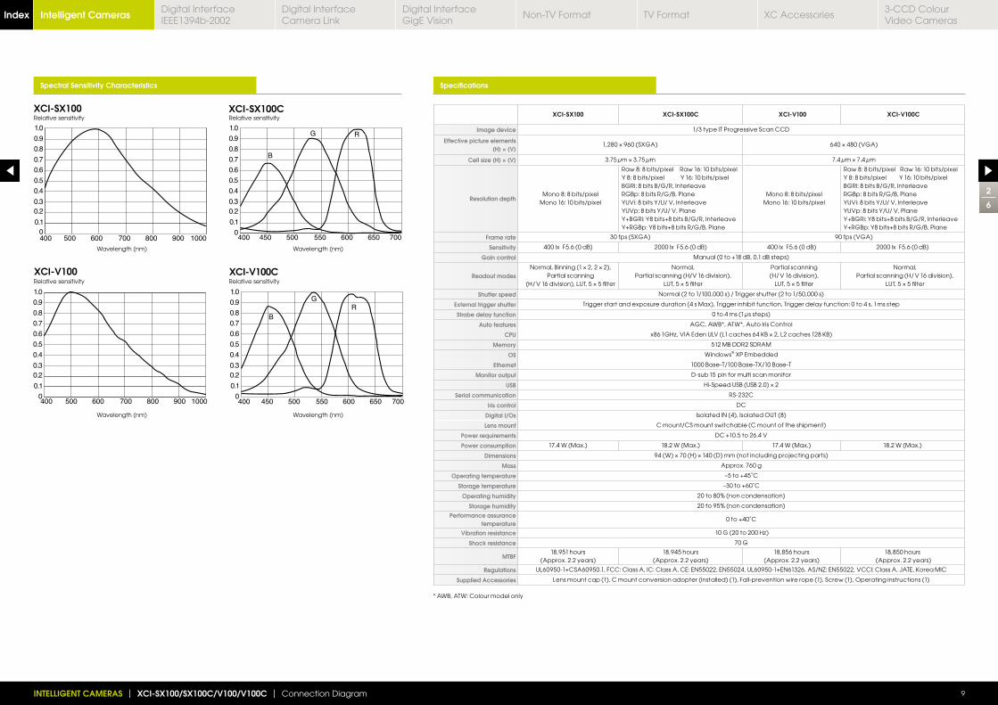
Spectral Sensitivity Characteristics Specifications
XCI-SX100 XCI-SX100C XCI-V100 XCI-V100C
Image device 1/3 type IT Progressive Scan CCD
Effective picture elements (H) × (V)
1,280 960 (SXGA) 640 480 (VGA)
Cell size (H) × (V) 3.75 μm 3.75 μm 7.4 μm 7.4 μm
Resolution depthMono 8: 8 bits/pixel
Mono 16: 10 bits/pixel
Raw 8: 8 bits/pixel Raw 16: 10 bits/pixelY 8: 8 bits/pixel Y 16: 10 bits/pixelBGRi: 8 bits B/G/R, Interleave RGBp: 8 bits R/G/B, PlaneYUVi: 8 bits Y/U/ V, Interleave YUVp: 8 bits Y/U/ V, PlaneY+BGRi: Y8 bits+8 bits B/G/R, InterleaveY+RGBp: Y8 bits+8 bits R/G/B, Plane
Mono 8: 8 bits/pixelMono 16: 10 bits/pixel
Raw 8: 8 bits/pixel Raw 16: 10 bits/pixelY 8: 8 bits/pixel Y 16: 10 bits/pixelBGRi: 8 bits B/G/R, InterleaveRGBp: 8 bits R/G/B, PlaneYUVi: 8 bits Y/U/ V, Interleave YUVp: 8 bits Y/U/ V, PlaneY+BGRi: Y8 bits+8 bits B/G/R, InterleaveY+RGBp: Y8 bits+8 bits R/G/B, Plane
Frame rate 30 fps (SXGA) 90 fps (VGA)
Sensitivity 400 lx F5.6 (0 dB) 2000 lx F5.6 (0 dB) 400 lx F5.6 (0 dB) 2000 lx F5.6 (0 dB)
Gain control Manual (0 to +18 dB, 0.1 dB steps)
Readout modesNormal, Binning (1 2, 2 2),
Partial scanning (H/ V 16 division), LUT, 5 5 filter
Normal,Partial scanning (H/V 16 division),
LUT, 5 5 filter
Partial scanning (H/ V 16 division),
LUT, 5 5 filter
Normal,Partial scanning (H/ V 16 division),
LUT, 5 5 filter
Shutter speed Normal (2 to 1/100,000 s) / Trigger shutter (2 to 1/50,000 s)
External trigger shutter Trigger start and exposure duration (4 s Max), Trigger inhibit function, Trigger delay function: 0 to 4 s, 1 ms step
Strobe delay function 0 to 4 ms (1 μs steps)
Auto features AGC, AWB*, ATW*, Auto Iris Control
CPU
Memory 512 MB DDR2 SDRAM
OS Windows® XP Embedded
Ethernet 1000 Base-T/100 Base-TX/10 Base-T
Monitor output D-sub 15 pin for multi scan monitor
USB Hi-Speed USB (USB 2.0) 2
Serial communication RS-232C
Iris control DC
Digital I/Os Isolated IN (4), Isolated OUT (8)
Lens mount C mount/CS mount switchable (C mount of the shipment)
Power requirements DC +10.5 to 26.4 V
Power consumption 17.4 W (Max.) 18.2 W (Max.) 17.4 W (Max.) 18.2 W (Max.)
Dimensions 94 (W) 70 (H) 140 (D) mm (not including projecting parts)
Mass Approx. 760 g
Operating temperature –5 to +45˚C
Storage temperature –30 to +60˚C
Operating humidity 20 to 80% (non condensation)
Storage humidity 20 to 95% (non condensation)
Performance assurance temperature
0 to +40˚C
Vibration resistance 10 G (
Shock resistance 70 G
MTBF18,951 hours
(Approx. 2.2 years)18,945 hours
(Approx. 2.2 years)18,856 hours
(Approx. 2.2 years)18,850 hours
(Approx. 2.2 years)
Regulations
Supplied Accessories Lens mount cap (1), C mount conversion adopter (installed) (1), Fall-prevention wire rope (1), Screw (1), Operating instructions (1)
XCI-SX100
XCI-V100 XCI-V100C
XCI-SX100CRelative sensitivity Relative sensitivity
Wavelength (nm)
Wavelength (nm)
Wavelength (nm)
Wavelength (nm)
Relative sensitivity Relative sensitivity
2
6
INTELLIGENT CAMERAS | XCI-SX100/SX100C/V100/V100C | Connection Diagram 9
* AWB, ATW: Colour model only
Intelligent CamerasIndex Digital Interface IEEE1394b-2002
Digital Interface Camera Link
Digital InterfaceGigE Vision
Non-TV Format TV Format XC Accessories3-CCD Colour Video Cameras
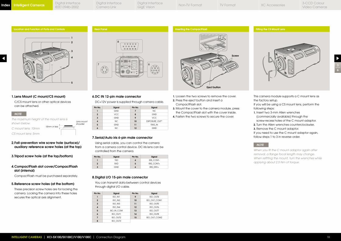
Location and Function of Parts and Controls Rear Panel Inserting the CompactFlash Fitting the CS Mount Lens
67
8
6. DC IN 12-pin male connector
DC+12V power is supplied through camera cable.
1. Lens Mount (C mount/CS mount)
C/CS mount lens or other optical devices can be attached.
NOTE
The maximum height of the mount lens is shown below.
C mount lens: 10mm
CS mount lens: 5mm
2. Fall-prevention wire screw hole (surface)/auxiliary reference screw holes (at the top)
3. Tripod screw hole (at the top/bottom)
4. CompactFlash slot cover/CompactFlash slot (internal)
CompactFlash must be purchased separately.
5. Reference screw holes (at the bottom)
These precision screw holes are for locking the camera. Locking the camera into these holes secures the optical axis alignment.
7. Serial/Auto iris 6-pin male connector
Using serial cable, you can control the camera from a camera control device. DC iris lens can be controlled from the camera.
8. Digital I/O 15-pin male connector
You can transmit data between control devices through digital I/O cable.
Pin No. Signal Pin No. Signal
1 GND 7 NC
2 VCC 8 GND
3 GND 9 VCC
4 NC 10 EXPOSURE_OUT*
5 GND 11 TRIG_IN
6 NC 12 GND
Pin No. Signal Pin No. Signal
1 ISO_IN1 9 ISO_OUT4
2 ISO_IN2 10 ISO_OUT_COM1
3 ISO_IN3 11 ISO_OUT5
4 ISO_IN4 12 ISO_OUT6
5 ISO_IN_COM 13 ISO_OUT7
6 ISO_OUT1 14 ISO_OUT8
7 ISO_OUT2 15 ISO_OUT_COM2
8 ISO_OUT3
Pin No. Signal Pin No. Signal
1 TXD 4 IRIS_CONT-
2 RXD 5 IRIS_CONT+
3 GND 6 IRIS_DRV+
1. Loosen the two screws to remove the cover.2. Press the eject button and insert a
CompactFlash slot. 3. Mount the cover to the camera module, press
the CompactFlash slot with the cover inside.4. Fasten the two screws to secure the cover.
This camera module supports a C mount lens as the factory setup.If you will be using a CS mount lens, perform the following steps:1. Insert two 3-mm Allen wrenches
(commercially available) through the screw-recess holes of the C mount adaptor.
2. Turn the Allen wrenches counterclockwise.3. Remove the C mount adaptor.If you need to use the C mount adaptor again, follow steps 1 to 3 in reverse order.
NOTE
When you fit the C mount adaptor again after removal, a flange focal length may change. When refitting the mount, turn the wrenches while applying about 2.5 Nm of torque.
10mm or less
Lens mount shoulder
1
2
3
4
5
Eject button
Screw
3
6
INTELLIGENT CAMERAS | XCI-SX100/SX100C/V100/V100C | Connection Diagram 10
Intelligent CamerasIndex Digital Interface IEEE1394b-2002
Digital Interface Camera Link
Digital InterfaceGigE Vision
Non-TV Format TV Format XC Accessories3-CCD Colour Video Cameras
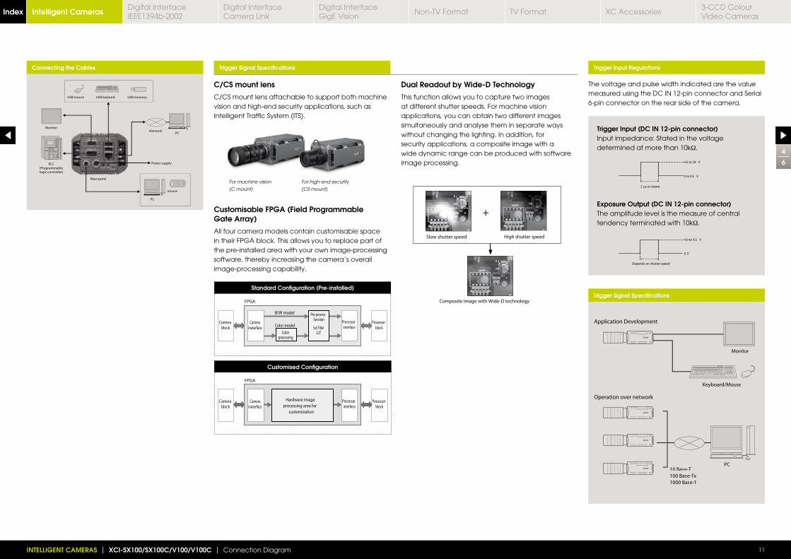
C/CS mount lens
C/CS mount lens attachable to support both machine vision and high-end security applications, such as Intelligent Traffic System (ITS).
Customisable FPGA (Field Programmable Gate Array)
All four camera models contain customisable space in their FPGA block. This allows you to replace part of the pre-installed area with your own image-processing software, thereby increasing the camera’s overall image-processing capability.
Connecting the Cables Trigger Signal Specifications
Trigger Signal Specifications
Trigger Input Regulations
The voltage and pulse width indicated are the value measured using the DC IN 12-pin connector and Serial 6-pin connector on the rear side of the camera.
Trigger Input (DC IN 12-pin connector) Input impedance: Stated in the voltage determined at more than 10kΩ.
Exposure Output (DC IN 12-pin connector)The amplitude level is the measure of central tendency terminated with 10kΩ.
more
Keyboard/Mouse
10 Base-T-100 Base-Tx-1000 Base-T-
For machine vision
(C mount)
For high-end security
(CS mount)
Dual Readout by Wide-D Technology
This function allows you to capture two images at different shutter speeds. For machine vision applications, you can obtain two different images simultaneously and analyse them in separate ways without changing the lighting. In addition, for security applications, a composite image with a wide dynamic range can be produced with software image processing.
Standard Configuration (Pre-installed)
Customised Configuration
4
6
INTELLIGENT CAMERAS | XCI-SX100/SX100C/V100/V100C | Connection Diagram 11
Intelligent CamerasIndex Digital Interface IEEE1394b-2002
Digital Interface Camera Link
Digital InterfaceGigE Vision
Non-TV Format TV Format XC Accessories3-CCD Colour Video Cameras
INTELLIGENT CAMERAS | XCI-SX100/SX100C/V100/V100C | Connection Diagram 12
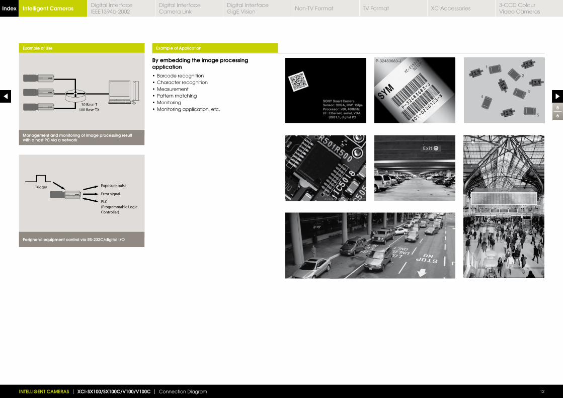
Example of Use
10 Base-T
100 Base-TX
Management and monitoring of image processing result with a host PC via a network
Exposure pulse
Error signal
PLC
(Programmable Logic
Controller)
Trigger
Peripheral equipment control via RS-232C/digital I/O
Example of Application
By embedding the image processing application
5
6
Intelligent CamerasIndex Digital Interface IEEE1394b-2002
Digital Interface Camera Link
Digital InterfaceGigE Vision
Non-TV Format TV Format XC Accessories3-CCD Colour Video Cameras
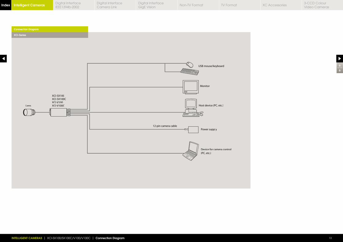
Monitor
Power supply
USB mouse/keyboard
Host device (PC, etc.)
Device for camera controlff
(PC, etc.)
12-pin camera cable
Lens
XCI-SX100XCI-SX100CXCI-V100XCI-V100C
INTELLIGENT CAMERAS | XCI-SX100/SX100C/V100/V100C | Connection Diagram 13
Connection Diagram
XCI-Series
6
6
Intelligent CamerasIndex Digital Interface IEEE1394b-2002
Digital Interface Camera Link
Digital InterfaceGigE Vision
Non-TV Format TV Format XC Accessories3-CCD Colour Video Cameras
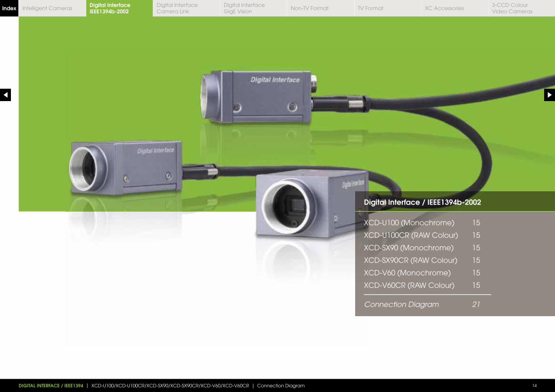
Digital Interface / IEEE1394b-2002
XCD-U100 (Monochrome) 15
XCD-U100CR (RAW Colour) 15
XCD-SX90 (Monochrome) 15
XCD-SX90CR (RAW Colour) 15
XCD-V60 (Monochrome) 15
XCD-V60CR (RAW Colour) 15
Connection Diagram 21
DIGITAL INTERFACE / IEEE1394 | XCD-U100/XCD-U100CR/XCD-SX90/XCD-SX90CR/XCD-V60/XCD-V60CR | Connection Diagram 14
Digital Interface IEEE1394b-2002Index Digital Interface
Camera LinkDigital InterfaceGigE Vision
Non-TV Format TV Format XC Accessories3-CCD Colour Video Cameras
Intelligent Cameras
Connection Diagram p21Dimensions (mm)
1
7
XCD-U100XCD-SX90XCD-V60
XCD-U100CRXCD-SX90CRXCD-V60CR
Digital Camera Module RAW ColourDigital Camera Module Monochrome
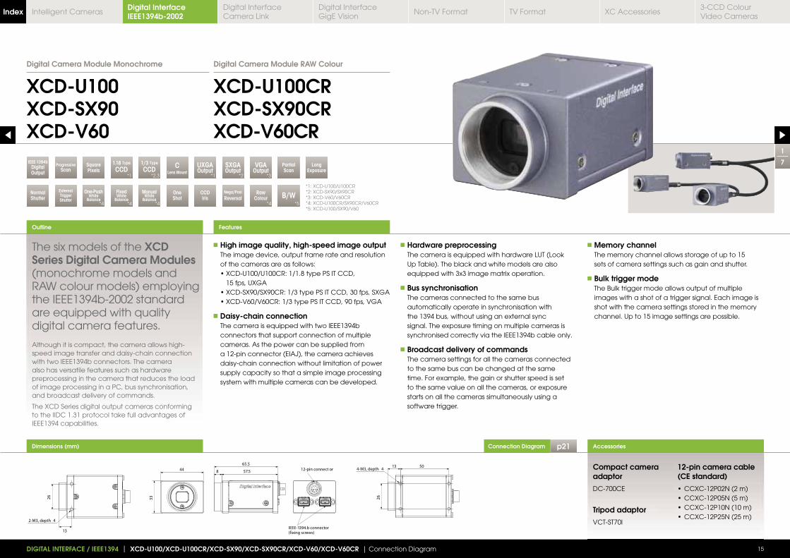
The six models of the XCD Series Digital Camera Modules (monochrome models and RAW colour models) employing the IEEE1394b-2002 standard are equipped with quality digital camera features.
Although it is compact, the camera allows high-speed image transfer and daisy-chain connection with two IEEE1394b connectors. The camera also has versatile features such as hardware preprocessing in the camera that reduces the load of image processing in a PC, bus synchronisation, and broadcast delivery of commands.
The XCD Series digital output cameras conforming to the IIDC 1.31 protocol take full advantages of IEEE1394 capabilities.
High image quality, high-speed image output The image device, output frame rate and resolution
of the cameras are as follows:
15 fps, UXGA
Daisy-chain connection The camera is equipped with two IEEE1394b
connectors that support connection of multiple cameras. As the power can be supplied from a 12-pin connector (EIAJ), the camera achieves daisy-chain connection without limitation of power supply capacity so that a simple image processing system with multiple cameras can be developed.
Hardware preprocessing The camera is equipped with hardware LUT (Look
Up Table). The black and white models are also equipped with 3x3 image matrix operation.
Bus synchronisation The cameras connected to the same bus
automatically operate in synchronisation with the 1394 bus, without using an external sync signal. The exposure timing on multiple cameras is synchronised correctly via the IEEE1394b cable only.
Broadcast delivery of commands The camera settings for all the cameras connected
to the same bus can be changed at the same time. For example, the gain or shutter speed is set to the same value on all the cameras, or exposure starts on all the cameras simultaneously using a software trigger.
Memory channel The memory channel allows storage of up to 15
sets of camera settings such as gain and shutter.
Bulk trigger mode The Bulk trigger mode allows output of multiple
images with a shot of a trigger signal. Each image is shot with the camera settings stored in the memory channel. Up to 15 image settings are possible.
Outline
15
Accessories
Features
Compact camera adaptor
DC-700CE
Tripod adaptor
VCT-ST70I
12-pin camera cable (CE standard)
DIGITAL INTERFACE / IEEE1394 | XCD-U100/XCD-U100CR/XCD-SX90/XCD-SX90CR/XCD-V60/XCD-V60CR | Connection Diagram
PartialScan
OneShot
CCDIris
RawColour
SXGAOutput
UXGAOutput
VGAOutput
B/WNormalShutter
One-PushWhite
Balance
FixedWhite
Balance
ManualWhite
Balance
ExternalTriggerShutter
LongExposure
SquarePixels
CLens Mount
1.18 Type
CCD1/3 Type
CCD
Nega/PosiReversal
IEEE-1394bDigitalOutput
ProgressiveScan
*1: XCD-U100/U100CR*2: XCD-SX90/SX90CR*3: XCD-V60/V60CR*4: XCD-U100CR/SX90CR/V60CR*5: XCD-U100/SX90/V60
*1
*4 *4 *4 *4 *5
*1 *2 *3*2,3
13
26
2-M3, depth 4
50
65.512-pin connect or
IEEE-1394.b connector(fixing screws)
57.5844
13
33
4-M3, depth 4
5013
26
4-M3, depth 4
Digital Interface IEEE1394b-2002Index Digital Interface
Camera LinkDigital InterfaceGigE Vision
Non-TV Format TV Format XC Accessories3-CCD Colour Video Cameras
Intelligent Cameras
Spectral Sensitivity CharacteristicsFeatures
2
7
16DIGITAL INTERFACE / IEEE1394 | XCD-U100/XCD-U100CR/XCD-SX90/XCD-SX90CR/XCD-V60/XCD-V60CR | Connection Diagram
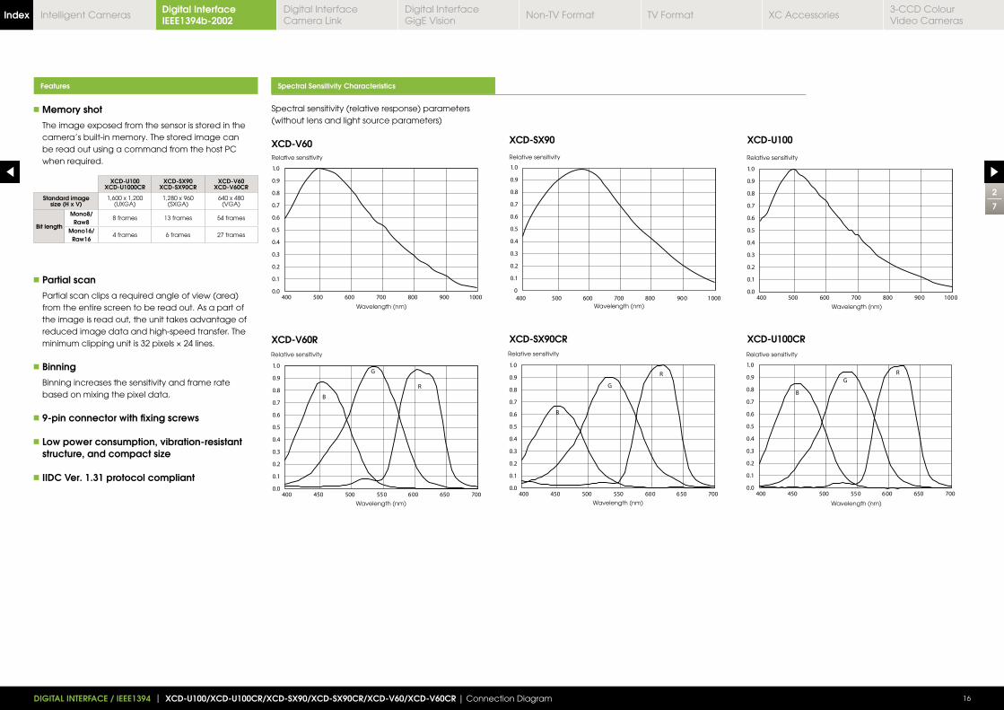
Memory shot
The image exposed from the sensor is stored in the camera’s built-in memory. The stored image can be read out using a command from the host PC when required.
Partial scan
Partial scan clips a required angle of view (area) from the entire screen to be read out. As a part of the image is read out, the unit takes advantage of reduced image data and high-speed transfer. The
Binning
Binning increases the sensitivity and frame rate based on mixing the pixel data.
9-pin connector with fixing screws
Low power consumption, vibration-resistant structure, and compact size
IIDC Ver. 1.31 protocol compliant
Spectral sensitivity (relative response) parameters (without lens and light source parameters)
XCD-V60
XCD-V60R
XCD-SX90
XCD-SX90CR
XCD-U100
XCD-U100CR
Relative sensitivity
Wavelength (nm)
Relative sensitivity
Wavelength (nm)
Relative sensitivity
Wavelength (nm)
Relative sensitivity
Wavelength (nm)
Relative sensitivity
Wavelength (nm)
Relative sensitivity
Wavelength (nm)
XCD-U100XCD-U1000CR
XCD-SX90XCD-SX90CR
XCD-V60XCD-V60CR
Standard image size (H x V)
1,600 x 1,200(UXGA)
1,280 x 960(SXGA)
640 x 480(VGA)
Bit length
Mono8/Raw8
8 frames 13 frames 54 frames
Mono16/Raw16
4 frames 6 frames 27 frames
Digital Interface IEEE1394b-2002Index Digital Interface
Camera LinkDigital InterfaceGigE Vision
Non-TV Format TV Format XC Accessories3-CCD Colour Video Cameras
Intelligent Cameras
Specifications
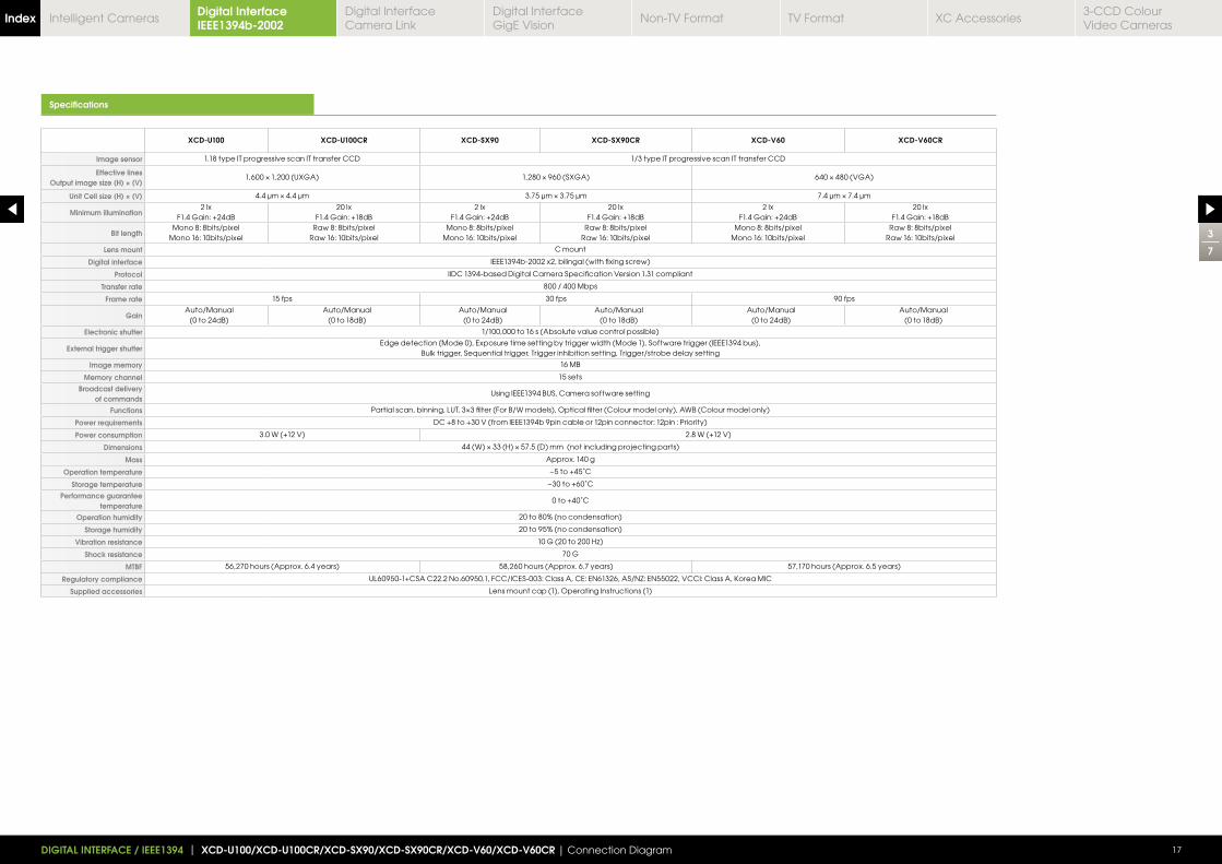
XCD-U100 XCD-U100CR XCD-SX90 XCD-SX90CR XCD-V60 XCD-V60CR
Image sensor 1.18 type IT progressive scan IT transfer CCD 1/3 type IT progressive scan IT transfer CCD
Effective lines Output image size (H) × (V)
1,600 1,200 (UXGA) 1,280 960 (SXGA) 640 480 (VGA)
Unit Cell size (H) × (V) 4.4 μm 4.4 μm 3.75 μm 3.75 μm 7.4 μm 7.4 μm
Minimum illumination2 lx
F1.4 Gain: +24dB20 lx
F1.4 Gain: +18dB2 lx
F1.4 Gain: +24dB20 lx
F1.4 Gain: +18dB2 lx
F1.4 Gain: +24dB20 lx
F1.4 Gain: +18dB
Bit lengthMono 8: 8bits/pixel
Mono 16: 10bits/pixelRaw 8: 8bits/pixel
Raw 16: 10bits/pixelMono 8: 8bits/pixel
Mono 16: 10bits/pixelRaw 8: 8bits/pixel
Raw 16: 10bits/pixelMono 8: 8bits/pixel
Mono 16: 10bits/pixelRaw 8: 8bits/pixel
Raw 16: 10bits/pixel
Lens mount C mount
Digital interface IEEE1394b-2002 x2, bilingal (with fixing screw)
Protocol IIDC 1394-based Digital Camera Specification Version 1.31 compliant
Transfer rate 800 / 400 Mbps
Frame rate 15 fps 30 fps 90 fps
GainAuto/Manual
(0 to 24dB)Auto/Manual
(0 to 18dB)Auto/Manual
(0 to 24dB)Auto/Manual
(0 to 18dB)Auto/Manual
(0 to 24dB)Auto/Manual
(0 to 18dB)
Electronic shutter 1/100,000 to 16 s (Absolute value control possible)
External trigger shutterEdge detection (Mode 0), Exposure time setting by trigger width (Mode 1), Software trigger (IEEE1394 bus),
Bulk trigger, Sequential trigger, Trigger inhibition setting, Trigger/strobe delay setting
Image memory 16 MB
Memory channel 15 sets
Broadcast delivery of commands
Using IEEE1394 BUS, Camera software setting
Functions
Power requirements DC +8 to +30 V (from IEEE1394b 9pin cable or 12pin connector: 12pin : Priority)
Power consumption 3.0 W (+12 V) 2.8 W (+12 V)
Dimensions
Mass Approx. 140 g
Operation temperature −5 to +45˚C
Storage temperature −30 to +60˚C
Performance guarantee temperature
0 to +40˚C
Operation humidity 20 to 80% (no condensation)
Storage humidity 20 to 95% (no condensation)
Vibration resistance
Shock resistance 70 G
MTBF 56,270 hours (Approx. 6.4 years) 58,260 hours (Approx. 6.7 years) 57,170 hours (Approx. 6.5 years)
Regulatory compliance
Supplied accessories Lens mount cap (1), Operating Instructions (1)
3
7
17DIGITAL INTERFACE / IEEE1394 | XCD-U100/XCD-U100CR/XCD-SX90/XCD-SX90CR/XCD-V60/XCD-V60CR | Connection Diagram
Digital Interface IEEE1394b-2002Index Digital Interface
Camera LinkDigital InterfaceGigE Vision
Non-TV Format TV Format XC Accessories3-CCD Colour Video Cameras
Intelligent Cameras
Location and Function of Parts and Controls Rear and Connector Pin Assignments Gain Shutter
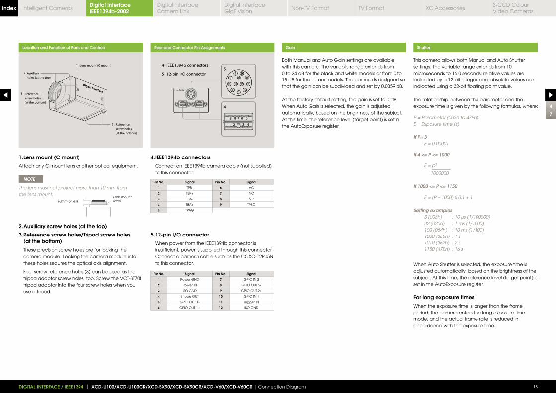
4. IEEE1394b connectors
Connect an IEEE1394b camera cable (not supplied) to this connector.
1. Lens mount (C mount)
Attach any C mount lens or other optical equipment.
NOTE
The lens must not project more than 10 mm from the lens mount.
2. Auxiliary screw holes (at the top)
3. Reference screw holes/Tripod screw holes (at the bottom)
These precision screw holes are for locking the camera module. Locking the camera module into these holes secures the optical axis alignment.
Four screw reference holes (3) can be used as the tripod adaptor screw holes, too. Screw the VCT-ST70I tripod adaptor into the four screw holes when you use a tripod.
5. 12-pin I/O connector
When power from the IEEE1394b connector is insufficient, power is supplied through this connector.
Connect a camera cable such as the CCXC-12P05N to this connector.
Pin No. Signal Pin No. Signal
1 TPB- 6 VG
2 TBP+ 7 NC
3 TBA- 8 VP
4 TBA+ 9 TPBG
5 TPAG
Pin No. Signal Pin No. Signal
1 Power GND 7 GPIO IN 2
2 Power IN 8 GPIO OUT 2-
3 ISO GND 9 GPIO OUT 2+
4 Strobe OUT 10 GPIO IN 1
5 GPIO OUT 1- 11 Trigger IN
6 GPIO OUT 1+ 12 ISO GND
Both Manual and Auto Gain settings are available with this camera. The variable range extends from 0 to 24 dB for the black and white models or from 0 to 18 dB for the colour models. The camera is designed so that the gain can be subdivided and set by 0.0359 dB.
At the factory default setting, the gain is set to 0 dB. When Auto Gain is selected, the gain is adjusted automatically, based on the brightness of the subject. At this time, the reference level (target point) is set in the AutoExposure register.
This camera allows both Manual and Auto Shutter settings. The variable range extends from 10 microseconds to 16.0 seconds; relative values are indicated by a 12-bit integer, and absolute values are indicated using a 32-bit floating point value.
The relationship between the parameter and the exposure time is given by the following formulas, where:
P = Parameter (003h to 47Eh)E = Exposure time (s) If P= 3 E = 0.00001
If 4 <= P <= 1000
E = p2
1000000 If 1000 <= P <= 1150
E = (P – 1000) x 0.1 + 1
Setting examples 3 (003h) : 10 μs (1/100000) 32 (020h) : 1 ms (1/1000) 100 (064h) : 10 ms (1/100) 1000 (3E8h) : 1 s 1010 (3F2h) : 2 s 1150 (47Eh) : 16 s
When Auto Shutter is selected, the exposure time is adjusted automatically, based on the brightness of the subject. At this time, the reference level (target point) is set in the AutoExposure register.
For long exposure times
When the exposure time is longer than the frame period, the camera enters the long exposure time mode, and the actual frame rate is reduced in accordance with the exposure time.
10mm or lessLens mount face
4
7
18DIGITAL INTERFACE / IEEE1394 | XCD-U100/XCD-U100CR/XCD-SX90/XCD-SX90CR/XCD-V60/XCD-V60CR | Connection Diagram
Digital Interface IEEE1394b-2002Index Digital Interface
Camera LinkDigital InterfaceGigE Vision
Non-TV Format TV Format XC Accessories3-CCD Colour Video Cameras
Intelligent Cameras
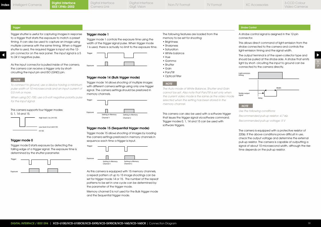
Trigger shutter is useful for capturing images in response to a trigger that starts the exposure to match a preset timing. It can also be used to capture an image using multiple cameras with the same timing. When a trigger shutter is used, the required trigger is input via the 12-pin connector on the rear panel. The input signal is a 5 to 24 V negative pulse.
As the input connector is pulled inside of the camera, the camera can receive a trigger only by short-circuiting the input pin and ISO (GND) pin.
NOTE
To connect to ground, use a device having a minimum pulse width of 10 microseconds and an input current of 0.5 mA or more.
When using DC-700, use a 5-volt negative polarity pulse for the input signal.
This camera supports four trigger modes: 0, 1, 14 and 15.
Trigger mode 0
Trigger mode 0 starts exposure by detecting the falling edge of a trigger signal. The exposure time is determined by the shutter parameter.
Trigger mode 1
Trigger mode 1 controls the exposure time using the width of the trigger signal pulse. When trigger mode 1 is used, there is actually no limit to the exposure time.
Trigger mode 14 (Bulk trigger mode)
Trigger mode 14 allows shooting of multiple images with different camera settings using only one trigger signal. The camera settings should be prestored in memory channels.
Trigger mode 15 (Sequential trigger mode)
Trigger mode 15 allows shooting of images by loading the camera settings prestored in memory channels in sequence each time a trigger is input.
As this camera is equipped with 15 memory channels, a repeat pattern of up to 15 image shootings can be set for trigger mode 14 or 15. The number of the repeat patterns to be set in one cycle can be determined by the parameter of the trigger mode.
Memory channel 0 is not used for the Bulk trigger mode and the Sequential trigger mode.
The following features are loaded from the memory to be set for shooting:
NOTE
The Auto mode of White Balance, Shutter and Gain cannot be set. Also note that Pan/Tilt is set only when the current video mode is the same as the video mode selected when the setting has been stored in the memory channel.
This camera can also be used with a software trigger that issues the trigger signal via software command. Trigger modes 0, 1, 14 and 15 can be used with software triggers.
Trigger Strobe Control
A strobe control signal is assigned in the 12-pin connector.
This allows direct command of light-emission from the strobe connected to the camera and controls the light-emission timing and the signal width.
The output terminal is of the open-collector type and should be pulled at the strobe side. A strobe that emits light by short- circuiting the input to ground can be connected to the camera directly.
NOTE
Use the following conditions:
Recommended pull-up resistor: 4.7 kΩ
Recommended pull-up voltage: 5 V
The camera is equipped with a protective resistor of 220Ω. If the above conditions prove difficult in use, check the output voltage and determine the external pull-up resistor. The camera is capable of outputting a signal of about 10 microsecond width, although the rise time depends on the pull-up resistor.
5
7
19DIGITAL INTERFACE / IEEE1394 | XCD-U100/XCD-U100CR/XCD-SX90/XCD-SX90CR/XCD-V60/XCD-V60CR | Connection Diagram
Digital Interface IEEE1394b-2002Index Digital Interface
Camera LinkDigital InterfaceGigE Vision
Non-TV Format TV Format XC Accessories3-CCD Colour Video Cameras
Intelligent Cameras
The camera is equipped with Memory Shot that temporarily stores an image in the frame memory inside the camera and transfers it later.
When multiple cameras are connected in the same bus, all the cameras may not output images at the same time due to the restriction of 800 Mbps band. Memory Shot may resolve this inconvenience.
When exposure starts, each camera stores an image in the frame memory without allocating the isochronous resource.
When outputting, each PC outputs the image from the camera allocating the isochronous resource.
The number of images to be stored depends on the video mode.
Timing used to start exposure is synchronised with the 1394 bus time cycle register.
If cameras are connected to the same bus, they are automatically synchronised in a 1394 bus operation. As 800 Mbps band restriction can affect the synchronisation, you must set the video mode in which the cameras can transmit a video signal at the same time.
1394 synchronisation does not work in long exposure mode and Partial scan mode. In a long exposure, the exposure time is set longer than the image transmission cycle.
1394 bus synchronisation includes up to 1H cycle jitter. Hardware external synchronisation will ensure greater accuracy.
This feature controls the colour density.
This feature controls the white balance by setting the R and B levels relative to the G level.
The camera also supports the Auto white balance by which the camera automatically adjusts the white balance.
The normal 1394 communication method specifies the node number at the host side so that only a specified camera responds to the command.
If the node number is set to 63, all the cameras connected to the same bus can receive the command simultaneously, i.e., only one command issued from the host can control multiple cameras at the same time.
All the commands including the video mode setting and the feature control are capable of broadcasting except the block writing command.
When setting different types of cameras using a broadcast command, be careful not to issue a command that the cameras do not support.
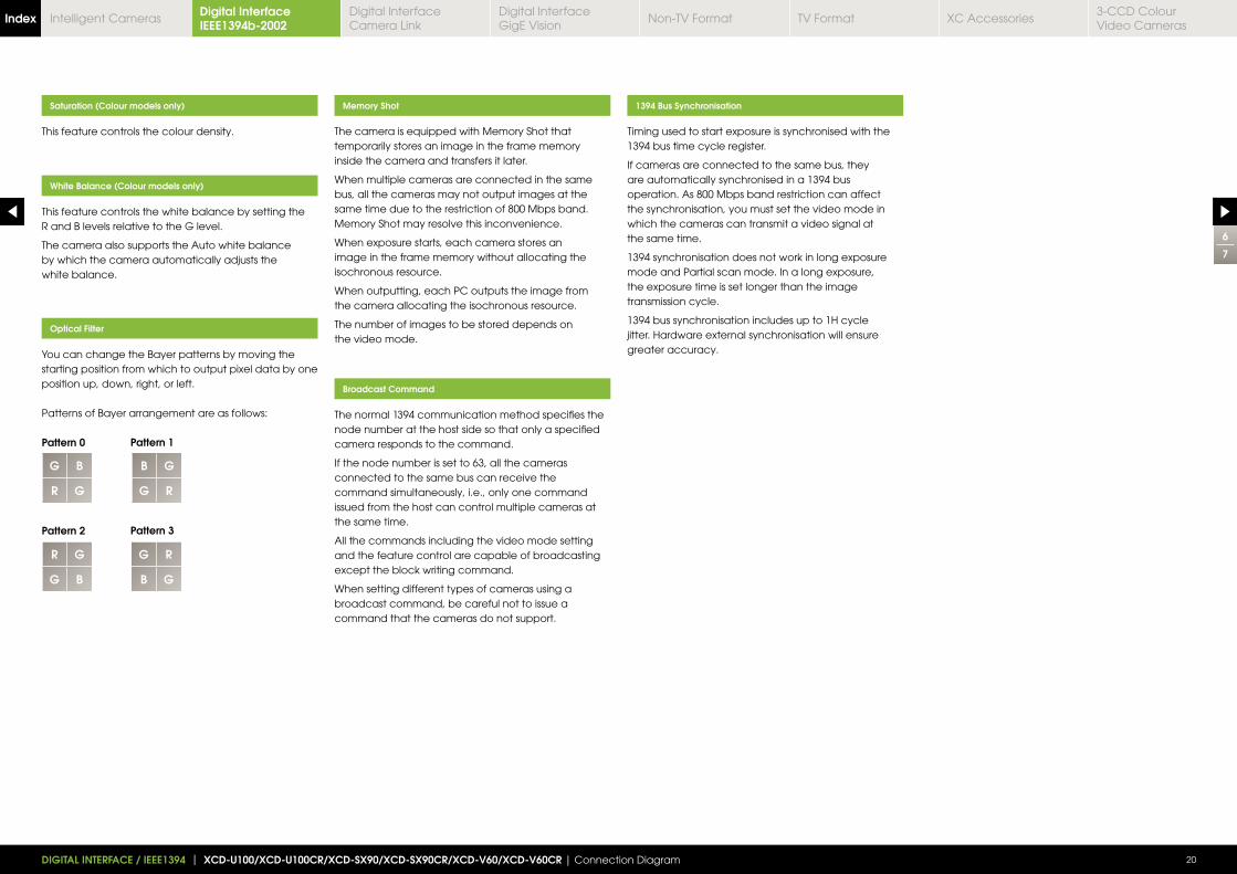
You can change the Bayer patterns by moving the starting position from which to output pixel data by one position up, down, right, or left.
Patterns of Bayer arrangement are as follows:
Pattern 0
Pattern 2
Saturation (Colour models only)
White Balance (Colour models only)
Broadcast Command
Optical Filter
Memory Shot 1394 Bus Synchronisation
6
7
20DIGITAL INTERFACE / IEEE1394 | XCD-U100/XCD-U100CR/XCD-SX90/XCD-SX90CR/XCD-V60/XCD-V60CR | Connection Diagram
G B
R G
B G
G R
Pattern 1
Pattern 3
R G
G B
G R
B G
Digital Interface IEEE1394b-2002Index Digital Interface
Camera LinkDigital InterfaceGigE Vision
Non-TV Format TV Format XC Accessories3-CCD Colour Video Cameras
Intelligent Cameras
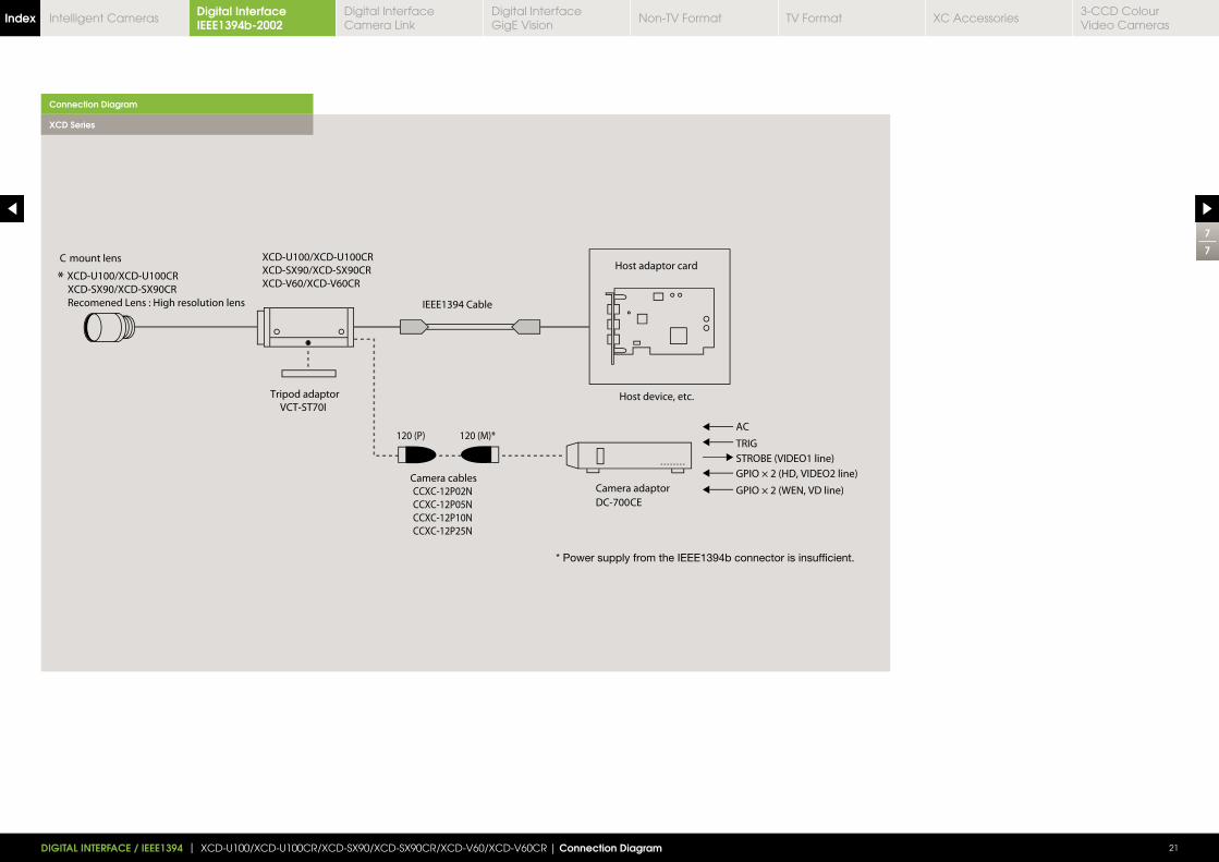
Connection Diagram
7
7
21DIGITAL INTERFACE / IEEE1394 | XCD-U100/XCD-U100CR/XCD-SX90/XCD-SX90CR/XCD-V60/XCD-V60CR | Connection Diagram
XCD Series
Digital Interface IEEE1394b-2002Index Digital Interface
Camera LinkDigital InterfaceGigE Vision
Non-TV Format TV Format XC Accessories3-CCD Colour Video Cameras
Intelligent Cameras
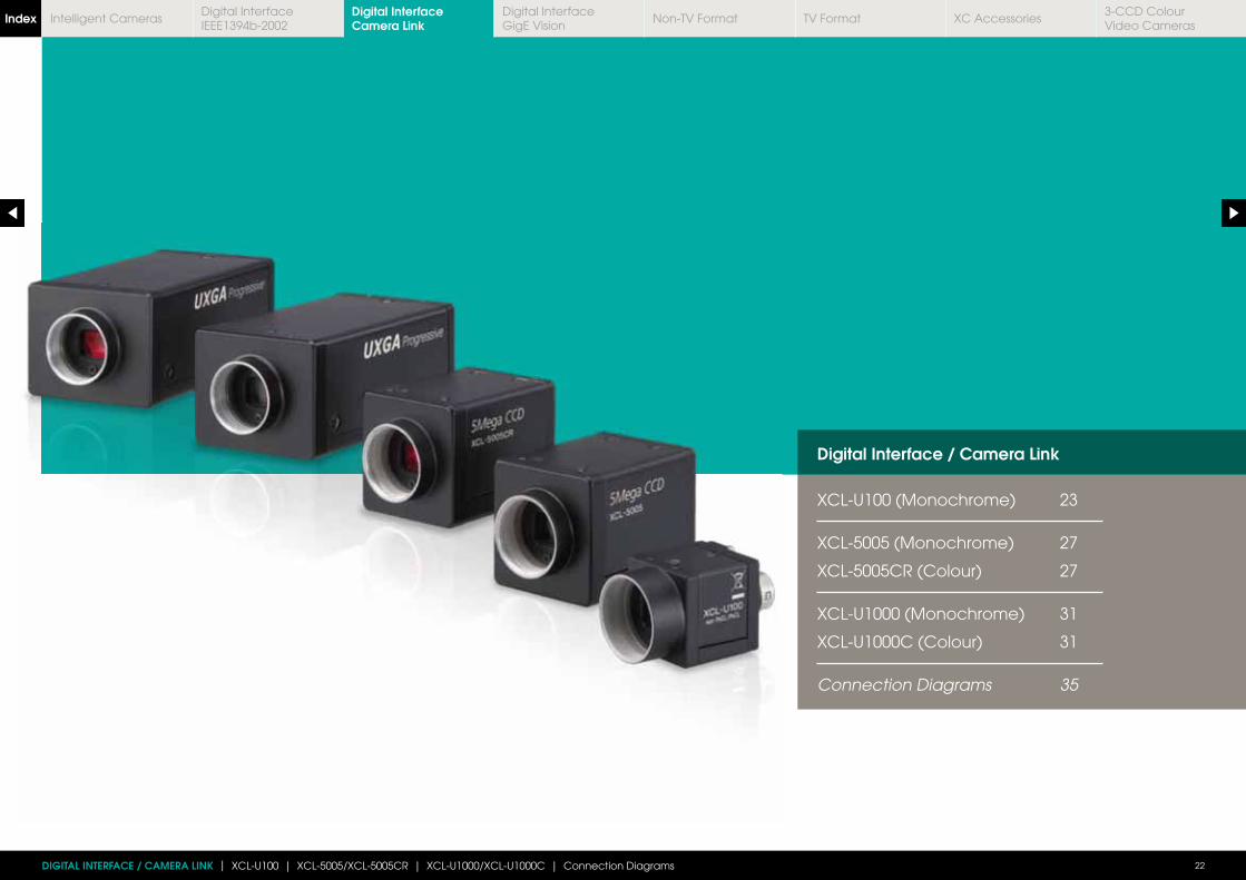
Digital Interface / Camera Link
XCL-U100 (Monochrome) 23
XCL-5005 (Monochrome) 27
XCL-5005CR (Colour) 27
XCL-U1000 (Monochrome) 31
XCL-U1000C (Colour) 31
Connection Diagrams 35
DIGITAL INTERFACE / CAMERA LINK | XCL-U100 | XCL-5005/XCL-5005CR | XCL-U1000/XCL-U1000C | Connection Diagrams 22
Digital Interface Camera LinkIndex Digital Interface
IEEE1394b-2002Digital InterfaceGigE Vision
Non-TV Format TV Format XC Accessories3-CCD Colour Video Cameras
Intelligent Cameras
Connection Diagram p35Dimensions (mm)
1
4
XCL-U100 NEW
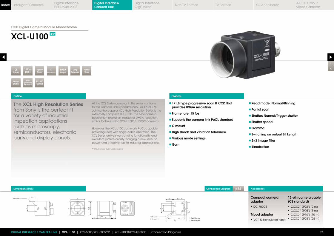
CCD Digital Camera Module Monochrome
The XCL High Resolution Series from Sony is the perfect fit for a variety of industrial inspection applications such as microscopy, semiconductors, electronic parts and display panels.
All the XCL Series cameras in this series conform to the Camera Link standard (non-PoCL/PoCL*). Joining the popular XCL High Resolution Series is the extremely compact XCL-U100. This new camera boasts high-resolution images of UXGA resolution, similar to the existing XCL-U1000/U1000C cameras.
However, the XCL-U100 camera is PoCL-capable, providing users with single-cable operation. The XCL Series delivers outstanding functionality and excellent picture quality, bringing a new level of power and effectiveness to industrial applications.
*PoCL (Power over Camera Link)
1/1.8 type progressive scan IT CCD that provides UXGA resolution
Frame rate: 15 fps
Supports the camera link PoCL standard
C mount
High shock and vibration tolerance
Various mode settings
Gain
Read mode: Normal/Binning
Partial scan
Shutter: Normal/Trigger shutter
Shutter speed
Gamma
Switching an output Bit Length
3×3 image filter
Binarisation
Outline
23
Accessories
Features
Compact camera adaptor
Tripod adaptor
12-pin camera cable (CE standard)
DIGITAL INTERFACE / CAMERA LINK | XCL-U100 | XCL-5005/XCL-5005CR | XCL-U1000/XCL-U1000C | Connection Diagrams
Mode 2(Non-Reset mode)
Reversal
PartialScan
UXGAOutput
NormalShutter
LongExposure
SquarePixels
CLens Mount
1.18 Type
CCDCL
Output
RS232CControl
Digital Interface Camera LinkIndex Digital Interface
IEEE1394b-2002Digital InterfaceGigE Vision
Non-TV Format TV Format XC Accessories3-CCD Colour Video Cameras
Intelligent Cameras
Spectral Sensitivity Characteristics Specifications
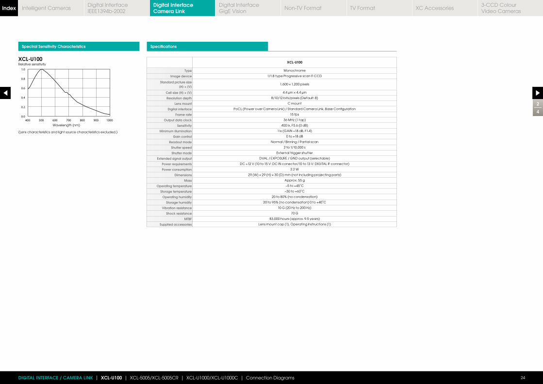
XCL-U100
Type Monochrome
Image device 1/1.8 type Progressive scan IT CCD
Standard picture size (H) × (V)
Cell size (H) × (V)
Resolution depth 8/10/12 bits/pixels (Default: 8)
Lens mount C mount
Digital interface PoCL (Power over Camera Link) / Standard Camera Link, Base Configuration
Frame rate 15 fps
Output data clock
Sensitivity 400 lx, F5.6 (0 dB)
Minimum illumination 1 lx (GAIN +18 dB, F1.4)
Gain control 0 to +18 dB
Readout mode Normal / Binning / Partial scan
Shutter speed 2 to 1/10,000 s
Shutter mode External trigger shutter
Extended signal output DVAL / EXPOSURE / GND output (selectable)
Power requirements DC +12 V (10 to 15 V: DC IN conector/10 to 13 V: DIGITAL IF connector)
Power consumption 2.2 W
Dimensions
Mass Approx. 55 g
Operating temperature –5 to +45˚C
Storage temperature –30 to +60˚C
Operating humidity 20 to 80% (no condensation)
Storage humidity 20 to 95% (no condensation) 0 to +40˚C
Vibration resistance
Shock resistance 70 G
MTBF 83.000 hours (approx. 9.5 years)
Supplied accessories Lens mount cap (1), Operating Instructions (1)
XCL-U100Relative sensitivity
Wavelength (nm)
(Lens characteristics and light source characteristics excluded.)
2
4
24DIGITAL INTERFACE / CAMERA LINK | XCL-U100 | XCL-5005/XCL-5005CR | XCL-U1000/XCL-U1000C | Connection Diagrams
Digital Interface Camera LinkIndex Digital Interface
IEEE1394b-2002Digital InterfaceGigE Vision
Non-TV Format TV Format XC Accessories3-CCD Colour Video Cameras
Intelligent Cameras
Location and Function of Parts and Controls Rear Panel Connector Pin Assignments
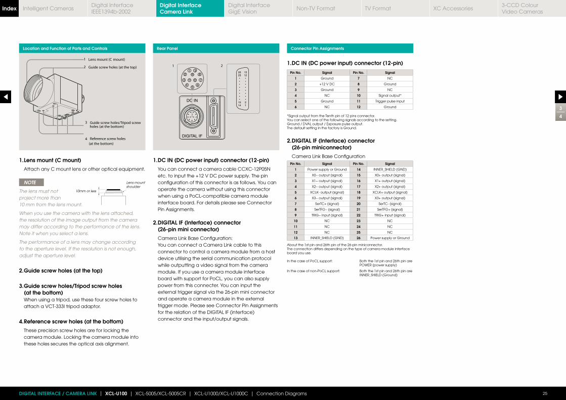
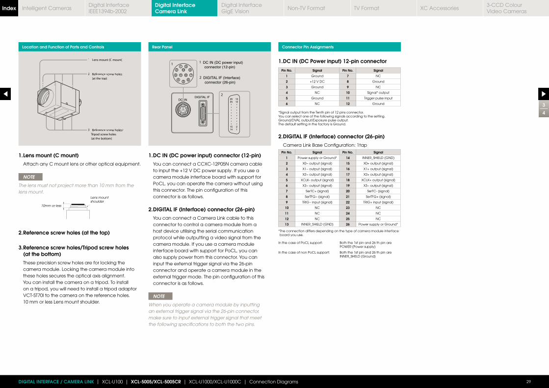
1. DC IN (DC power input) connector (12-pin)
You can connect a camera cable CCXC-12P05N etc. to input the +12 V DC power supply. The pin configuration of this connector is as follows. You can operate the camera without using this connector when using a PoCL-compatible camera module interface board. For details please see Connector Pin Assignments.
2. DIGITAL IF (Interface) connector (26-pin mini connector)
Camera Link Base Configuration: You can connect a Camera Link cable to this
connector to control a camera module from a host device utilising the serial communication protocol while outputting a video signal from the camera module. If you use a camera module interface board with support for PoCL, you can also supply power from this connecter. You can input the external trigger signal via the 26-pin mini connector and operate a camera module in the external trigger mode. Please see Connector Pin Assignments for the relation of the DIGITAL IF (interface) connector and the input/output signals.
1. Lens mount (C mount)
Attach any C mount lens or other optical equipment.
NOTE
The lens must not project more than 10 mm from the lens mount.
When you use the camera with the lens attached, the resolution of the image output from the camera may differ according to the performance of the lens. Note it when you select a lens.
The performance of a lens may change according to the aperture level. If the resolution is not enough, adjust the aperture level.
2. Guide screw holes (at the top)
3. Guide screw holes/Tripod screw holes (at the bottom) When using a tripod, use these four screw holes to attach a VCT-333I tripod adaptor.
4. Reference screw holes (at the bottom)
These precision screw holes are for locking the camera module. Locking the camera module into these holes secures the optical axis alignment.
1. DC IN (DC power input) connector (12-pin)
Pin No. Signal Pin No. Signal
1 Ground 7 NC
2 +12 V DC 8 Ground
3 Ground 9 NC
4 NC 10 Signal output*
5 Ground 11 Trigger pulse input
6 NC 12 Ground *Signal output from the Tenth pin of 12 pins connector. You can select one of the following signals according to the setting. Ground / DVAL output / Exposure pulse output. The default setting in the factory is Ground.
2. DIGITAL IF (Interface) connector (26-pin miniconnector)
Camera Link Base Configuration
Pin No. Signal Pin No. Signal
1 Power supply or Ground 14 INNER_SHIELD (GND)
2 X0− output (signal) 15 X0+ output (signal)
3 X1− output (signal) 16 X1+ output (signal)
4 X2− output (signal) 17 X2+ output (signal)
5 18
6 X3− output (signal) 19 X3+ output (signal)
7 SerTC+ (signal) 20 SerTC- (signal)
8 SerTFG− (signal) 21 SerTFG+ (signal)
9 TRIG− input (signal) 22 TRIG+ input (signal)
10 NC 23 NC
11 NC 24 NC
12 NC 25 NC
13 INNER_SHIELD (GND) 26 Power supply or Ground About the 1st pin and 26th pin of the 26-pin miniconnector.The connection differs depending on the type of camera module interface board you use.
In the case of PoCL support: Both the 1st pin and 26th pin are POWER (power supply)
In the case of non-PoCL support: Both the 1st pin and 26th pin are INNER_SHIELD (Ground)
10mm or less
Lens mount shoulder
3
4
25DIGITAL INTERFACE / CAMERA LINK | XCL-U100 | XCL-5005/XCL-5005CR | XCL-U1000/XCL-U1000C | Connection Diagrams
Digital Interface Camera LinkIndex Digital Interface
IEEE1394b-2002Digital InterfaceGigE Vision
Non-TV Format TV Format XC Accessories3-CCD Colour Video Cameras
Intelligent Cameras
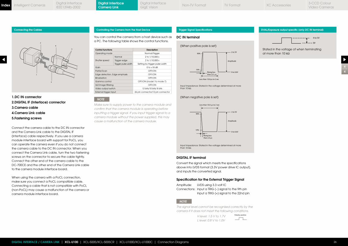
You can control the camera from a host device such as a PC. The following table shows the control functions.
Control functions Description
Operating mode Normal/Trigger
Shutter speed
Normal 2 to 1/10,000 s
Trigger edge 2 to 1/10,000 s
Trigger pulse width Setting by trigger pulse width
Gain 0 to +18 dB
Partial Scan OFF/ON
Edge detection, Edge emphasis OFF/ON
Binarisation OFF/ON
Gamma control OFF/ON (mode1 to mode 7)
3x3 Image filtering OFF/ON
Video output switch 12 bits/10 bits/ 8 bits
External trigger input 26 pin connector/12 pin connector
NOTE
Make sure to supply power to the camera module and confirm that the camera module is operating before inputting a trigger signal. If you input trigger signal to a camera module without the power supplied, this may cause a malfunction of the camera module.
1. DC IN connector
2.DIGITAL IF (Interface) connector
3.Camera cable
4.Camera Link cable
5.Fastening screws
Connect the camera cable to the DC IN connector and the Camera Link cable to the DIGITAL IF (interface) cable respectively. If you use a camera module interface board with support for PoCL, you can operate the camera even if you do not connect the camera cable to the DC IN connector. When you connect the Camera Link cable, turn the two fastening screws on the connector to secure the cable tightly. Connect the other end of the camera cable to the DC-700CE and the other end of the Camera Link cable to the camera module interface board.
When using the camera with a PoCL connection, make sure you connect a PoCL compatible cable. Connecting a cable that is not compatible with PoCL (non-PoCL) may cause a malfunction of the camera or camera module interface board.
Connecting the Cables Controlling the Camera from the Host Device Trigger Signal Specifications DVAL/Exposure output specific (only DC IN terminal)
Stated in the voltage of when terminating at more than 10 kΩ
(When positive pole is set)
Input Impedance: Stated in the voltage determined at more than 10 kΩ.
(When negative pole is set)
Input Impedance: Stated in the voltage determined at more than 10 kΩ.
DC IN terminal
4
4
26DIGITAL INTERFACE / CAMERA LINK | XCL-U100 | XCL-5005/XCL-5005CR | XCL-U1000/XCL-U1000C | Connection Diagrams
DIGITAL IF terminal
Convert the signal which meets the specifications above into LVDS format (3.3V power drive IC output), and inputs the converted signal.
Specification for the External Trigger Signal
Amplitude: LVDS using 3.3 volt ICConnections: Input a TRIG (−) signal to the 9th pin Input a TRIG (+) signal to the 22nd pin
NOTE
The signal level cannot be recognised correctly by the camera if it does not meet the following conditions.
H level: 1.5 V to 1.7V L level: 0.8 V to 1.0V
Digital Interface Camera LinkIndex Digital Interface
IEEE1394b-2002Digital InterfaceGigE Vision
Non-TV Format TV Format XC Accessories3-CCD Colour Video Cameras
Intelligent Cameras
Connection Diagram p35Dimensions (mm)
1
4
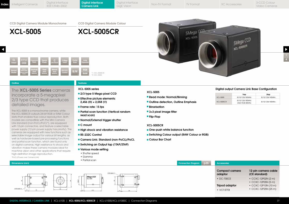
XCL-5005 XCL-5005CRCCD Digital Camera Module Colour
The XCL-5005 Series cameras incorporate a 5-megapixel 2/3 type CCD that produces detailed images. The XCL-5005 is a monochrome camera, while the XCL-5005CR outputs 24-bit RGB or RAW Colour data that enables true colour reproduction. Both models are compatible with the Mini Camera Link standard (non-PoCL/PoCL*), are equipped with 12-pin connectors, and feature a selectable power supply (12-pin power supply has priority). The cameras are equipped with new functions such as selectable image output for various bit lengths, as well as hardware-based pre-processing functions and partial scan function, which are found only on digital cameras. High resistance to shock and vibration makes these camera modules ideal for machine vision and other applications that require high-definition image reproduction.*PoCL (Power over Camera Link)
XCL-5005 series
2/3 type 5 Mega pixel CCD
Effective picture elements: 2,456 (H) × 2,058 (V)
Frame rate: 15 fps
Partial scan function (Vertical random read scan)
Normal/External trigger shutter
C mount
High shock and vibration resistance
RS-232C Control
Camera Link: Standard (non-PoCL)/PoCL
Switching an Output tap (1TAP/2TAP)
Various mode setting
XCL-5005
Read mode: Normal/Binning
Outline detection, Outline Emphasis
Binarisation
3×3 pixel image filter
Flip-Flop
XCL-5005CR
One-push white balance function
Switching Colour output (RAW Colour or RGB)
Colour Bar Chart
Digital output Camera Link Base Configuration
1tap 2tap
XCL-5005
XCL-5005CR
Outline
27
Accessories
Features
*1: XCL-5005CR*2: XCL-5005
DIGITAL INTERFACE / CAMERA LINK | XCL-U100 | XCL-5005/XCL-5005CR | XCL-U1000/XCL-U1000C | Connection Diagrams
LongExposure
PartialScan
NormalShutter
5 MegaOutput
SquarePixels
CLens MountOutput
CL 2/3 Type
CCDProgressive
Scan
Mode 2(Reset mode)
External Trigger Shutter
One-PushWhite
Balance*1
RGBRAW
*1
FixedWhite
Balance*1
ManualWhite
Balance*1
B/W*2
RS232CControl
Compact camera adaptor
Tripod adaptor
12-pin camera cable (CE standard)
CCD Digital Camera Module Monochrome
Digital Interface Camera LinkIndex Digital Interface
IEEE1394b-2002Digital InterfaceGigE Vision
Non-TV Format TV Format XC Accessories3-CCD Colour Video Cameras
Intelligent Cameras
Spectral Sensitivity Characteristics Specifications
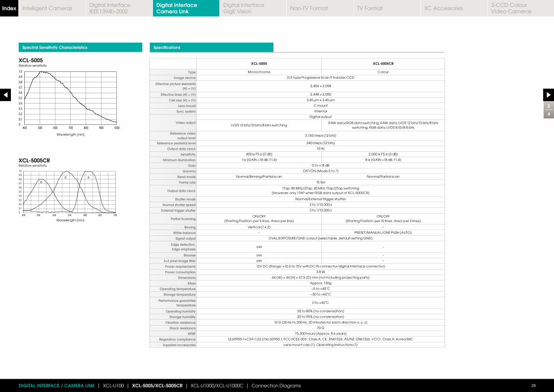
XCL-5005 XCL-5005CR
Type Monochrome Colour
Image device 2/3 type Progressive Scan IT transfer CCD
Effective picture elements (H) × (V)
Effective lines (H) × (V)
Cell size (H) × (V)
Lens mount C mount
Sync system Internal
Video output
Digital output
LVDS 12 bits/10 bits/8 bits switchingRAW data/RGB data switching, RAW data: LVDS 12 bits/10 bits/8 bits
switching, RGB data: LVDS R/G/B 8 bits
Reference video output level
3,760 steps (12 bits)
Reference pedestal level 240 steps (12 bits)
Output data clock
Sensitivity 400 lx F5.6 (0 dB) 2,000 lx F5.6 (0 dB)
Minimum illumination 1 lx (GAIN +18 dB, F1.4) 8 lx (GAIN +18 dB, F1.4)
Gain 0 to +18 dB
Gamma OFF/ON (Mode 0 to 7)
Read mode Normal/Binning/Partial scan Normal/Partial scan
Frame rate 15 fps
Output data clock(However, only 1TAP when RGB data output of XCL-5005CR)
Shutter mode Normal/External trigger shutter
Normal shutter speed 2 to 1/10,000 s
External trigger shutter 2 to 1/10,000 s
Partial ScanningON/OFF
(Starting Position: per 5 lines, Area: per line)ON/OFF
(Starting Position: per 10 lines, Area: per 2 lines)
Binning –
White balance – PRESET/MANUAL/ONE PUSH (AUTO)
Signal output DVAL/EXPOSURE/GND output (selectable, default setting GND)
Edge detection, Edge emphasis
yes –
Binarise yes –
3×3 pixel image filter yes –
Power requirements 12V DC (Range: +10.5 to 15V with DC IN connector/digital interface connector)
Power consumption 3.8 W
Dimensions
Mass Approx. 130g
Operating temperature −5 to +45˚C
Storage temperature −30 to +60˚C
Performance guarantee temperature
0 to +40˚C
Operating humidity 20 to 80% (no condensation)
Storage humidity 20 to 95% (no condensation)
Vibration resistance
Shock resistance 70 G
MTBF 75,300 hours (Approx. 8.6 years)
Regulatory compliance
Supplied accessories Lens mount cap (1), Operating Instructions (1)
XCL-5005
XCL-5005CR
Relative sensitivity
Relative sensitivity
Wavelength (nm)
Wavelength (nm)
2
4
28DIGITAL INTERFACE / CAMERA LINK | XCL-U100 | XCL-5005/XCL-5005CR | XCL-U1000/XCL-U1000C | Connection Diagrams
Digital Interface Camera LinkIndex Digital Interface
IEEE1394b-2002Digital InterfaceGigE Vision
Non-TV Format TV Format XC Accessories3-CCD Colour Video Cameras
Intelligent Cameras
Location and Function of Parts and Controls Rear Panel Connector Pin Assignments
2 Reference screw holes
(at the top)
3 Reference screw holes/
Tripod screw holes
(at the bottom)
1 Lens mount (C mount)
1. DC IN (DC power input) connector (12-pin)
You can connect a CCXC-12P05N camera cable to input the +12 V DC power supply. If you use a camera module interface board with support for PoCL, you can operate the camera without using this connector. The pin configuration of this connector is as follows.
2. DIGITAL IF (Interface) connector (26-pin)
You can connect a Camera Link cable to this connector to control a camera module from a host device utilising the serial communication protocol while outputting a video signal from the camera module. If you use a camera module interface board with support for PoCL, you can also supply power from this connector. You can input the external trigger signal via the 26-pin connector and operate a camera module in the external trigger mode. The pin configuration of this connector is as follows.
NOTE
When you operate a camera module by inputting an external trigger signal via the 26-pin connector, make sure to input external trigger signal that meet the following specifications to both the two pins.
1. Lens mount (C mount)
Attach any C mount lens or other optical equipment.
NOTE
The lens must not project more than 10 mm from the lens mount.
2. Reference screw holes (at the top)
3. Reference screw holes/Tripod screw holes (at the bottom)
These precision screw holes are for locking the camera module. Locking the camera module into these holes secures the optical axis alignment. You can install the camera on a tripod. To install on a tripod, you will need to install a tripod adaptor VCT-ST70I to the camera on the reference holes. 10 mm or less Lens mount shoulder.
10mm or less
Lens mount shoulder
3
4
29DIGITAL INTERFACE / CAMERA LINK | XCL-U100 | XCL-5005/XCL-5005CR | XCL-U1000/XCL-U1000C | Connection Diagrams
1. DC IN (DC Power input) 12-pin connector
Pin No. Signal Pin No. Signal
1 Ground 7 NC
2 +12 V DC 8 Ground
3 Ground 9 NC
4 NC 10 Signal* output
5 Ground 11 Trigger pulse input
6 NC 12 Ground *Signal output from the Tenth pin of 12 pins connector.You can select one of the following signals according to the setting.Ground/DVAL output/Exposure pulse output.The default setting in the factory is Ground.
2. DIGITAL IF (Interface) connector (26-pin)
Camera Link Base Configuration: 1tap
Pin No. Signal Pin No. Signal
1 Power supply or Ground* 14 INNER_SHIELD (GND)
2 X0− output (signal) 15 X0+ output (signal)
3 X1− output (signal) 16 X1+ output (signal)
4 X2− output (signal) 17 X2+ output (signal)
5 18
6 X3− output (signal) 19 X3− output (signal)
7 SerTC+ (signal) 20 SerTC- (signal)
8 SerTFG− (signal) 21 SerTFG+ (signal)
9 TRIG− input (signal) 22 TRIG+ input (signal)
10 NC 23 NC
11 NC 24 NC
12 NC 25 NC
13 INNER_SHIELD (GND) 26 Power supply or Ground* * The connection differs depending on the type of camera module interface board you use.
In the case of PoCL support: Both the 1st pin and 26 th pin are POWER (Power supply)
In the case of non PoCL support: Both the 1st pin and 26 th pin are INNER_SHELD (Ground)
Digital Interface Camera LinkIndex Digital Interface
IEEE1394b-2002Digital InterfaceGigE Vision
Non-TV Format TV Format XC Accessories3-CCD Colour Video Cameras
Intelligent Cameras
4
4
30DIGITAL INTERFACE / CAMERA LINK | XCL-U100 | XCL-5005/XCL-5005CR | XCL-U1000/XCL-U1000C | Connection Diagrams
You can control the camera from a host device such as a PC. The following table shows the control functions.
Control functions XCL-5005 XCL-5005CR
Operating mode Normal/Trigger
Shutter speed
Normal 2 to 1/10,000 s
TriggerTrigger edge: 2 to 1/10000s
Trigger pulse width: Setting by trigger pulse width
Gain 0 to +18 dB
Binning OFF/ON –
Partial Scan OFF/ON
Edge detection, Edge emphasis
OFF/ON –
Binarisation OFF/ON –
Gamma control OFF/ON (mode1 to mode 7)
3x3 Image filtering OFF/ON –
Video output switch 12 bits/10 bits/8 bits
External trigger input 26 pin connector/12 pin connector
Switch output tap 1 Tap/2 Tap
White balance RESET/MANUAL/ONE PUSH (AUTO)
Switch Colour output RAW data/RGB data
NOTE
Make sure to supply power to the camera module and confirm that the camera module is operating before inputting a trigger signal. If you input external signals to a camera module without the power supplied, this may cause a malfunction of the camera module.
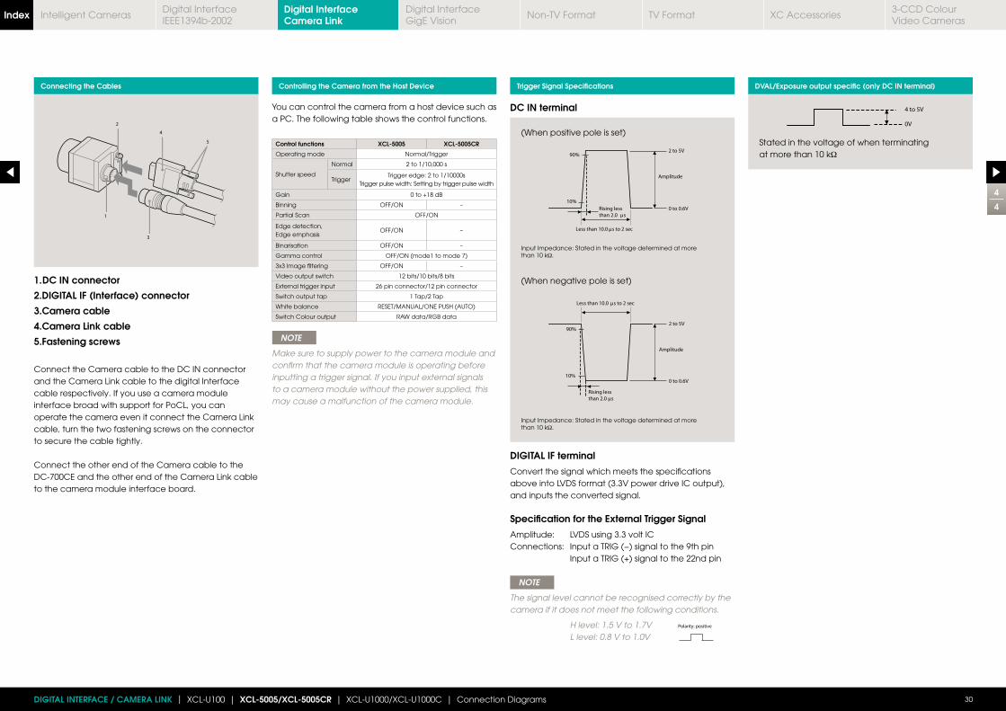
1. DC IN connector
2.DIGITAL IF (Interface) connector
3.Camera cable
4.Camera Link cable
5.Fastening screws
Connect the Camera cable to the DC IN connector and the Camera Link cable to the digital Interface cable respectively. If you use a camera module interface broad with support for PoCL, you can operate the camera even it connect the Camera Link cable, turn the two fastening screws on the connector to secure the cable tightly.
Connect the other end of the Camera cable to the DC-700CE and the other end of the Camera Link cable to the camera module interface board.
Connecting the Cables Controlling the Camera from the Host Device Trigger Signal Specifications DVAL/Exposure output specific (only DC IN terminal)
Stated in the voltage of when terminating at more than 10 kΩ
(When positive pole is set)
Input Impedance: Stated in the voltage determined at more than 10 kΩ.
(When negative pole is set)
Input Impedance: Stated in the voltage determined at more than 10 kΩ.
DC IN terminal
DIGITAL IF terminal
Convert the signal which meets the specifications above into LVDS format (3.3V power drive IC output), and inputs the converted signal.
Specification for the External Trigger Signal
Amplitude: LVDS using 3.3 volt ICConnections: Input a TRIG (−) signal to the 9th pin Input a TRIG (+) signal to the 22nd pin
NOTE
The signal level cannot be recognised correctly by the camera if it does not meet the following conditions.
H level: 1.5 V to 1.7V L level: 0.8 V to 1.0V
Digital Interface Camera LinkIndex Digital Interface
IEEE1394b-2002Digital InterfaceGigE Vision
Non-TV Format TV Format XC Accessories3-CCD Colour Video Cameras
Intelligent Cameras
Connection Diagram p36Dimensions (mm)
1
4
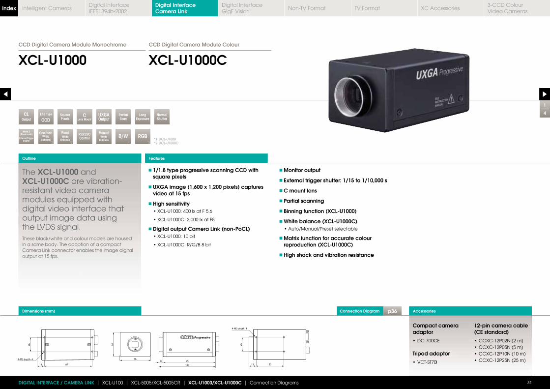
XCL-U1000 XCL-U1000CCCD Digital Camera Module ColourCCD Digital Camera Module Monochrome
The XCL-U1000 and XCL-U1000C are vibration-resistant video camera modules equipped with digital video interface that output image data using the LVDS signal. These black/white and colour models are housed in a same body. The adoption of a compact Camera Link connector enables the image digital output at 15 fps.
1/1.8 type progressive scanning CCD with square pixels
UXGA image (1,600 x 1,200 pixels) captures video at 15 fps
High sensitivity
Digital output Camera Link (non-PoCL)
Monitor output
External trigger shutter: 1/15 to 1/10,000 s
C mount lens
Partial scanning
Binning function (XCL-U1000)
White balance (XCL-U1000C)
Matrix function for accurate colour reproduction (XCL-U1000C)
High shock and vibration resistance
Outline
31
Accessories
Features
*1: XCL-U1000*2: XCL-U1000C
DIGITAL INTERFACE / CAMERA LINK | XCL-U100 | XCL-5005/XCL-5005CR | XCL-U1000/XCL-U1000C | Connection Diagrams
LongExposure
PartialScan
ManualWhite
Balance
SquarePixels
CLens MountOutput
CL 1.18 Type
CCDNormalShutter
Mode 2(Reset mode)
External Trigger Shutter
RS232CControl
UXGAOutput
FixedWhite
Balance*2
One-PushWhite
Balance*2
RGB*2
B/W*1
Compact camera adaptor
Tripod adaptor
12-pin camera cable (CE standard)
Digital Interface Camera LinkIndex Digital Interface
IEEE1394b-2002Digital InterfaceGigE Vision
Non-TV Format TV Format XC Accessories3-CCD Colour Video Cameras
Intelligent Cameras
Spectral Sensitivity Characteristics Specifications
XCL-U1000 (Typical Values)
XCL-U1000C (Typical Values)
Relative sensitivity
Relative sensitivity
Wavelength (nm)
Wavelength (nm)
2
4
32DIGITAL INTERFACE / CAMERA LINK | XCL-U100 | XCL-5005/XCL-5005CR | XCL-U1000/XCL-U1000C | Connection Diagrams
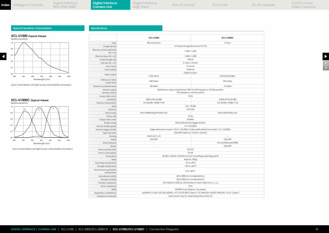
XCL-U1000 XCL-U1000C
Type Monochrome Colour
Image device 1/1.8 type Progressive scan IT CCD
Effective picture elements (H) × (V)
Effective lines (H) × (V)
Output image size UXGA
Cell size (H) × (V)
Lens mount C mount
Sync system Internal
Video outputDigital output
LVDS 10 bit LDVS R/G/B 8bit
Reference video output level
940 steps 235 steps
Reference pedestal level 64 steps 16 steps
Monitor output (analog output)
Output data clock
Sensitivity 400 lx F5.6 (0 dB) 2,000 lx F5.6 (0 dB)
Minimum illumination 2 lx (GAIN +18dB, F1.4) 4 lx (GAIN +18dB, F1.4)
Gain 0 to +18 dB
Gamma OFF/ON
Read mode Normal/Binning/Partial scan Normal/Partial scan
Frame rate 15 fps
Output data clock
Shutter mode Normal/External trigger shutter
Normal shutter speed 1 to 1/10,000 s
External trigger shutter Edge detection mode: 1/15 to 1/10,000 s, Pulse width detection mode: 1 to 1/10,000 s
High rate scan ON/OFF (Vertical 1/16V to 15/16V)
Binning –
Detail ON/OFF ON/OFF
White balance – Pre-set/Manual/AWB
Matrix – ON/OFF
Power requirements 12V DC
Power consumption 5.5 W
Dimensions
Mass Approx. 250g
Operating temperature −5 to +45˚C
Storage temperature −30 to +60˚C
Performance guarantee temperature
0 to +40˚C
Operating humidity 20 to 80% (no condensation)
Storage humidity 20 to 95% (no condensation)
Vibration resistance
Shock resistance 70 G
MTBF 49,059 hours (Approx. 5.6 years)
Regulatory compliance UL60950-1+CSA C22.2 No.60950.1, FCC/ICES-003: Class A, CE: EN61326, AS/NZ: EN61326, VCCI: Class A
Supplied accessories Lens mount cap (1), Operating Instructions (1)
(Lens characteristics and light source characteristics excluded.)
(Lens characteristics and light source characteristics excluded.)
Digital Interface Camera LinkIndex Digital Interface
IEEE1394b-2002Digital InterfaceGigE Vision
Non-TV Format TV Format XC Accessories3-CCD Colour Video Cameras
Intelligent Cameras
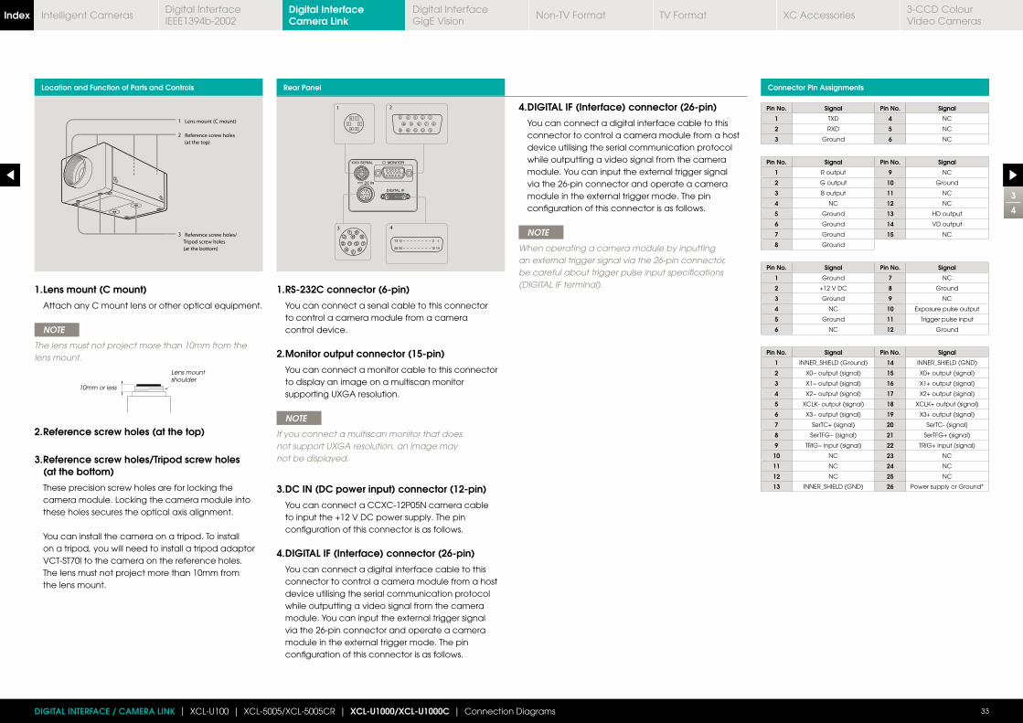
Location and Function of Parts and Controls Rear Panel Connector Pin Assignments
1. RS-232C connector (6-pin)
You can connect a senal cable to this connector to control a camera module from a camera control device.
2. Monitor output connector (15-pin)
You can connect a monitor cable to this connector to display an image on a multiscan monitor supporting UXGA resolution.
NOTE
If you connect a multiscan monitor that does not support UXGA resolution, an image may not be displayed.
3. DC IN (DC power input) connector (12-pin)
You can connect a CCXC-12P05N camera cable to input the +12 V DC power supply. The pin configuration of this connector is as follows.
4. DIGITAL IF (Interface) connector (26-pin)
You can connect a digital interface cable to this connector to control a camera module from a host device utilising the serial communication protocol while outputting a video signal from the camera module. You can input the external trigger signal via the 26-pin connector and operate a camera module in the external trigger mode. The pin configuration of this connector is as follows.
NOTE
When operating a camera module by inputting an external trigger signal via the 26-pin connector, be careful about trigger pulse input specifications (DIGITAL IF terminal).1. Lens mount (C mount)
Attach any C mount lens or other optical equipment.
NOTE
The lens must not project more than 10mm from the lens mount.
2. Reference screw holes (at the top)
3. Reference screw holes/Tripod screw holes (at the bottom)
These precision screw holes are for locking the camera module. Locking the camera module into these holes secures the optical axis alignment. You can install the camera on a tripod. To install on a tripod, you will need to install a tripod adaptor VCT-ST70I to the camera on the reference holes. The lens must not project more than 10mm from the lens mount.
Pin No. Signal Pin No. Signal
1 TXD 4 NC
2 RXD 5 NC
3 Ground 6 NC
Pin No. Signal Pin No. Signal
1 R output 9 NC
2 G output 10 Ground
3 B output 11 NC
4 NC 12 NC
5 Ground 13 HD output
6 Ground 14 VD output
7 Ground 15 NC
8 Ground
Pin No. Signal Pin No. Signal
1 Ground 7 NC
2 +12 V DC 8 Ground
3 Ground 9 NC
4 NC 10 Exposure pulse output
5 Ground 11 Trigger pulse input
6 NC 12 Ground
Pin No. Signal Pin No. Signal
1 INNER_SHIELD (Ground) 14 INNER_SHIELD (GND)
2 X0− output (signal) 15 X0+ output (signal)
3 X1− output (signal) 16 X1+ output (signal)
4 X2− output (signal) 17 X2+ output (signal)
5 18
6 X3− output (signal) 19 X3+ output (signal)
7 SerTC+ (signal) 20 SerTC- (signal)
8 SerTFG− (signal) 21 SerTFG+ (signal)
9 TRIG− input (signal) 22 TRIG+ input (signal)
10 NC 23 NC
11 NC 24 NC
12 NC 25 NC
13 INNER_SHIELD (GND) 26 Power supply or Ground*
10mm or less
Lens mount shoulder
3
4
33DIGITAL INTERFACE / CAMERA LINK | XCL-U100 | XCL-5005/XCL-5005CR | XCL-U1000/XCL-U1000C | Connection Diagrams
Digital Interface Camera LinkIndex Digital Interface
IEEE1394b-2002Digital InterfaceGigE Vision
Non-TV Format TV Format XC Accessories3-CCD Colour Video Cameras
Intelligent Cameras
You can control the camera from a host device such as a PC. The following table shows the control functions.You can send a command corresponding to the control items, with parameters for the desired settings, if necessary, from the host device to control the camera.
Control functions Description
Operating mode Normal/Trigger
Shutter speed
Normal 1 to 1/10000
Trigger edgeInternal setting: 1/15 to 1/10000
Setting by trigger pulse width
Gain 0 to +18 dB
Binning function (XCL-U1000 only) OFF/ON
Partial Scan function OFF/ON
Detail OFF/ON
External trigger input 26 pin connector/ 12 pin connector
White balance (XCL-U1000C only) Preset/Manual/AWB
Matrix (XCL-U1000C only) OFF/ON
NOTE
Make sure to supply power to the camera module and confirm that the camera module is operating before inputting a trigger signal.
If you input external signals to a camera module without the power supplied, this may cause a malfunction of the camera module.
4
4
34DIGITAL INTERFACE / CAMERA LINK | XCL-U100 | XCL-5005/XCL-5005CR | XCL-U1000/XCL-U1000C
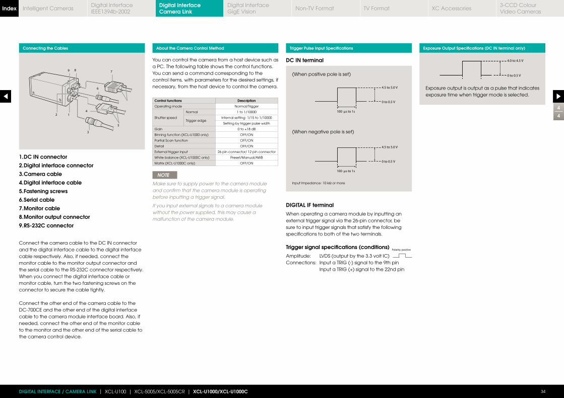
1. DC IN connector
2. Digital interface connector
3. Camera cable
4. Digital interface cable
5. Fastening screws
6. Serial cable
7. Monitor cable
8. Monitor output connector
9. RS-232C connector
Connect the camera cable to the DC IN connector and the digital interface cable to the digital interface cable respectively. Also, if needed, connect the monitor cable to the monitor output connector and the serial cable to the RS-232C connector respectively. When you connect the digital interface cable or monitor cable, turn the two fastening screws on the connector to secure the cable tightly.
Connect the other end of the camera cable to the DC-700CE and the other end of the digital interface cable to the camera module interface board. Also, if needed, connect the other end of the monitor cable to the monitor and the other end of the serial cable to the camera control device.
Connecting the Cables About the Camera Control Method Trigger Pulse Input Specifications Exposure Output Specifications (DC IN terminal only)
Exposure output is output as a pulse that indicates exposure time when trigger mode is selected.
(When positive pole is set)
(When negative pole is set)
Input Impedance: 10 kΩ or more
DC IN terminal
DIGITAL IF terminal
When operating a camera module by inputting an external trigger signal via the 26-pin connector, be sure to input trigger signals that satisfy the following specifications to both of the two terminals.
Trigger signal specifications (conditions)
Amplitude: LVDS (output by the 3.3 volt IC)Connections: Input a TRIG (-) signal to the 9th pin Input a TRIG (+) signal to the 22nd pin
Digital Interface Camera LinkIndex Digital Interface
IEEE1394b-2002Digital InterfaceGigE Vision
Non-TV Format TV Format XC Accessories3-CCD Colour Video Cameras
Intelligent Cameras
1
2
35DIGITAL INTERFACE / CAMERA LINK | XCL-U100 | XCL-5005/XCL-5005CR | XCL-U1000/XCL-U1000C | XCL-X700/XCL-V500 | Connection Diagrams
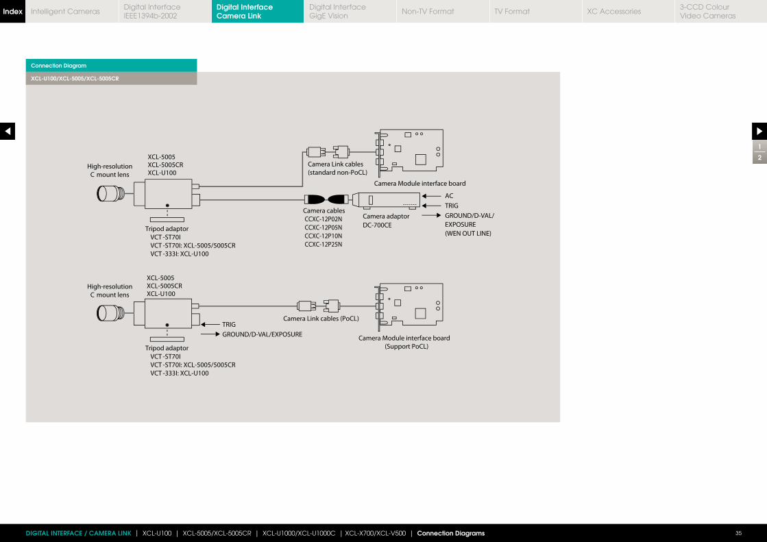
Connection Diagram
XCL-U100/XCL-5005/XCL-5005CR
Digital Interface Camera LinkIndex Digital Interface
IEEE1394b-2002Digital InterfaceGigE Vision
Non-TV Format TV Format XC Accessories3-CCD Colour Video Cameras
Intelligent Cameras
2
2
36DIGITAL INTERFACE / CAMERA LINK | XCL-U100 | XCL-5005/XCL-5005CR | XCL-U1000/XCL-U1000C | XCL-X700/XCL-V500 | Connection Diagrams
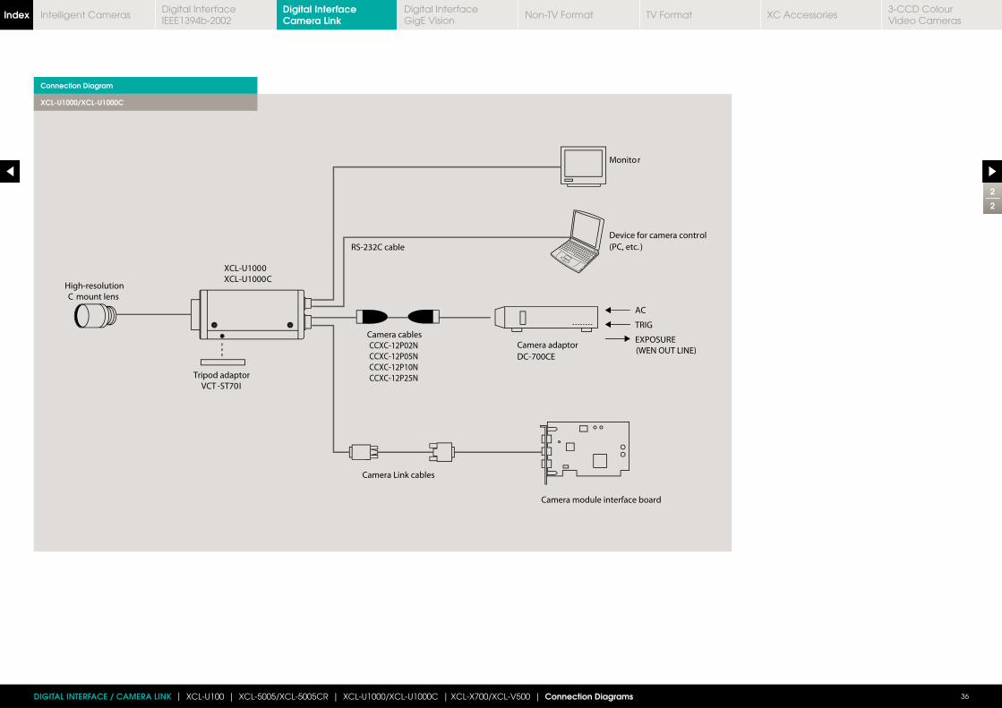
Connection Diagram
XCL-U1000/XCL-U1000C
Digital Interface Camera LinkIndex Digital Interface
IEEE1394b-2002Digital InterfaceGigE Vision
Non-TV Format TV Format XC Accessories3-CCD Colour Video Cameras
Intelligent Cameras
Digital Interface / GigE Vision
XCG-V60E 38
XCG-SX97E 38
XCG-SX99E 38
XCG-U100E 38
XCG-5005E 38
Connection Diagram 46
DIGITAL INTERFACE / GigE VISION | XCG-V60E | XCG-SX97E | XCG-SX99E | XCG-U100E | XCG-5005E | Connection Diagram 37
Digital InterfaceGigE VisionIndex Digital Interface
IEEE1394b-2002Digital Interface Camera Link
Non-TV Format TV Format XC Accessories3-CCD Colour Video Cameras
Intelligent Cameras
Connection Diagram p46
UXGAOutput
B/W
2/3 Type
CCD*4*2
1/1.8 Type
CCD*3
Dimensions (mm)
1
8
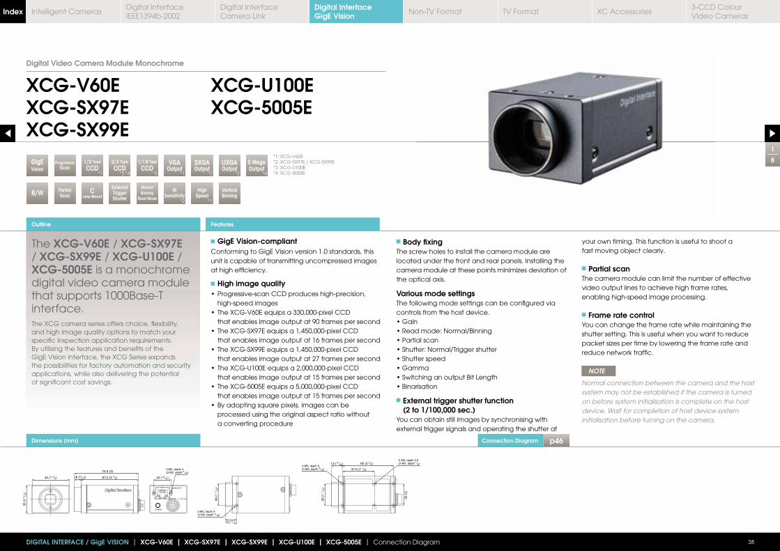
GigE Vision-compliantConforming to GigE Vision version 1.0 standards, thisunit is capable of transmitting uncompressed images at high efficiency.
High image quality
high-speed images
that enables image output at 90 frames per second
that enables image output at 16 frames per second
that enables image output at 27 frames per second
that enables image output at 15 frames per second
that enables image output at 15 frames per second
processed using the original aspect ratio without a converting procedure
Body fixingThe screw holes to install the camera module are located under the front and rear panels. Installing the
the optical axis.
Various mode settingsThe following mode settings can be configured via controls from the host device.
External trigger shutter function (2 to 1/100,000 sec.)
You can obtain still images by synchronising withexternal trigger signals and operating the shutter at
your own timing. This function is useful to shoot afast moving object clearly.
Partial scanThe camera module can limit the number of effectivevideo output lines to achieve high frame rates, enabling high-speed image processing.
Frame rate controlYou can change the frame rate while maintaining theshutter setting. This is useful when you want to reduce
reduce network traffic.
NOTE
Normal connection between the camera and the hostsystem may not be established if the camera is turned on before system initialisation is complete on the hostdevice. Wait for completion of host device systeminitialisation before turning on the camera.
Outline
DIGITAL INTERFACE / GigE VISION | XCG-V60E | XCG-SX97E | XCG-SX99E | XCG-U100E | XCG-5005E | Connection Diagram 38
Features
XCG-V60EXCG-SX97EXCG-SX99E
XCG-U100EXCG-5005E
Digital Video Camera Module Monochrome
2-M3, depth 4(2-M3, depth 3/16)
2-M2, depth 4(2-M2, depth 3/16)
4-M3, depth 4(4-M3, depth 3/16)
2-M2, depth 2.6(2-M2, depth 1/8)
The XCG-V60E / XCG-SX97E / XCG-SX99E / XCG-U100E / XCG-5005E is a monochrome digital video camera module that supports 1000Base-T interface.The XCG camera series offers choice, flexibility, and high image quality options to match your specific inspection application requirements. By utilising the features and benefits of the GigE Vision interface, the XCG Series expands the possibilities for factory automation and security applications, while also delivering the potential of significant cost savings.
External Trigger Shutter
High Speed
IR Sensitivity
PartialScan
CLens Mount
VisionGigE
Normal Binning
Read Mode
VGAOutput
SXGAOutput
5 MegaOutput
ProgressiveScan
Vertical Binning
*1: XCG-V60E*2: XCG-SX97E / XCG-SX99E*3: XCG-U100E*4: XCG-5005E
1/3 Type
CCD*1 *1
*2
*2
*1
*3 *4
Digital InterfaceGigE VisionIndex Digital Interface
IEEE1394b-2002Digital Interface Camera Link
Non-TV Format TV Format XC Accessories3-CCD Colour Video Cameras
Intelligent Cameras
Accessories
2
8
39DIGITAL INTERFACE / GigE VISION | XCG-V60E | XCG-SX97E | XCG-SX99E | XCG-U100E | XCG-5005E | Connection Diagram
CCXC-12P02N (2 m) / 05N (5 m) / 10N (10 m) / 25N (25 m) camera cableThis is attached to the DC IN connector of the camera module and is used for power supply and exchange of trigger signals.
C mount lensFor XCG-SX97E/SX99E/U100E/5005E, use a high-resolution lens.
DC-700/700CE camera adaptorThis is connected to the camera module to enable power supply from ordinaryAC power source.
VCT-ST701 tripod adaptorThis attaches to the bottom of the camera module to fix the camera module to a tripod.
Network card (commercially available)Install the board in the expansionslot of the host device (ex: computer).Select a card that is appropriatefor your system and thatsupports 1000Base-T andjumbo packets.
LAN cable (commercially available)This cable connects to the RJ45 connector on the rear panel of the camera module.Image/control signals are transmittedvia this cable. Select a LAN cable thatsupports 1000Base-T (CAT5e or higher cable standard). Depending on the attributesof the LAN cable, images may becomeless clear and the camera module maybecome unstable. Be sure to use aLAN cable that has sufficientnoise reduction.
ate
Spectral Sensitivity Characteristics
XCG-V60E
XCG-SX97E / XCG SX99E XCG-5005E
XCG-U100ERelative sensitivity Relative sensitivity
Wavelength (nm)(Without lens and light source parameters.)
Wavelength (nm)(Without lens and light source parameters.)
Wavelength (nm)(Without lens and light source parameters.)
Wavelength (nm)(Without lens and light source parameters.)
Relative sensitivity Relative sensitivity
Digital InterfaceGigE VisionIndex Digital Interface
IEEE1394b-2002Digital Interface Camera Link
Non-TV Format TV Format XC Accessories3-CCD Colour Video Cameras
Intelligent Cameras
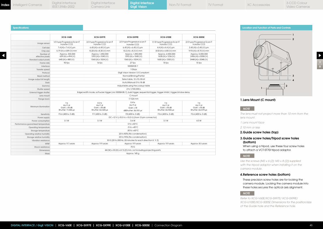
Specifications
XCG-V60E XCG-SX97E XCG-SX99E XCG-U100E XCG-5005E
Image sensor1/3 type Progressive Scan IT
transfer CCD2/3 type Progressive Scan IT
transfer CCD2/3-type Progressive scan IT
transfer CCD1/1.8 type Progressive Scan IT
transfer CCD2/3 type Progressive Scan IT
transfer CCD
Cell size 7.4 (H) x 7.4 (V) μm 6.45 (H) x 6.45 (V) μm 4.4 (H) x 4.4 (V) μm 3.45 (H) x 3.45 (V) μm
Chip size 5.79 (H) x 4.89 (V) mm 10.20 (H) x 8.30 (V) mm 8.50 (H) x 6.80 (V) mm 9.93 (H) x 8.70 (V) mm
Number of effective pixels
Approx. 330,000659 (H) x 494 (V)
Approx. 1,450,0001392 (H) x 1040 (V)
Approx. 1,450,000 Approx. 2,000,0001628 (H) x 1236 (V)
Approx. 5,000,0002456 (H) x 2058 (V)
Standard output pixels 640 (H) x 480 (V) 1360 (H) x 1024 (V) 1600 (H) x 1200 (V) 2448 (H) x 2048 (V)
Frame rate 90 fps 16 fps 27 fps 15 fps 15 fps
Interface 1000BASE-T
Transfer speed 1 Gbps
Protocol GigE Vision Version 1.0 Compliant
Read method Normal/Binning/Partial
Image output bit length Selectable, 12-/10-/8-bit
Gain Auto/Manual: 0 to 18 dB
Gamma Adjustable using the Lookup table
Shutter speed 2 to 1/100,000 s
External trigger shutter Edge/width mode, software trigger (via 1000BASE-T), bulk trigger, sequential trigger, trigger inhibit, trigger/strobe delay
Lens mount C mount
Flange back 17.526 mm
Minimum illumination
1 lxIris: F1.4
Gain: +18 dBShutter: 11,046 μs
0.2 lxIris: F1.4
Gain: +18 dBShutter: 62,320 μs
0.4 lxIris: F1.4
Gain: +18dBShutter: 36,931 μs
1 lxIris: F1.4
Gain: +18 dBShutter: 66,506 μs
1 lxIris: F1.4
Gain: +18 dBShutter: 66,570 μs
Sensitivity F5.6 (400 lx, 0 dB) F11 (400 lx, 0 dB) F8 (400 lx, 0 dB) F5.6 (400 lx, 0 dB) F5.6 (400 lx, 0 dB)
Power supply DC +12 V (+10.5 to +15.0 V) (from 12-pin connector)
Power consumption 3.1 W 3.1 W 3.6 W 3.1 W 4.3 W
Performance guaranteed temperature 0 to +40°C
Operating temperature -5 to +45°C
Storage temperature -30 to +60°C
Operating relative humidity 20 to 80% (No condensation)
Storage relative humidity 20 to 95% (No condensation)
Vibration resistance
MTBF Approx. 9.7 years Approx. 9.9 years Approx. 9.9 years Approx. 9.9 years Approx. 8.5 years
Shock resistance 70 G
Dimensions 44 (W) x 33 (H) x 67.5 (D) mm, not including projecting parts
Mass Approx. 145 g
3
8
40DIGITAL INTERFACE / GigE VISION | XCG-V60E | XCG-SX97E | XCG-SX99E | XCG-U100E | XCG-5005E | Connection Diagram
Location and Function of Parts and Controls
1. Lens Mount (C mount)
NOTE
The lens must not project more than 10 mm from the lens mount.
1 Lens mount face
2 10 mm or less
2. Guide screw holes (top)
3. Guide screw holes/Tripod screw holes (bottom) When using a tripod, use these four screw holes to attach a VCT-ST70I tripod adaptor.
NOTE
Use the screws (M2 × 6 (2); M3 × 8 (2)) supplied with the tripod adaptor when installing it on the camera module.
4. Reference screw holes (bottom)
These precision screw holes are for locking the camera module. Locking the camera module into these holes secures the optical axis alignment.
NOTE
Refer to XCG-V60E/XCG-SX97E/ XCG-SX99E/ XCG-U100E/XCG-5005E Dimensions for the position/size of the Guide hole and the Reference hole.
1
2
3
4
12
Digital InterfaceGigE VisionIndex Digital Interface
IEEE1394b-2002Digital Interface Camera Link
Non-TV Format TV Format XC Accessories3-CCD Colour Video Cameras
Intelligent Cameras
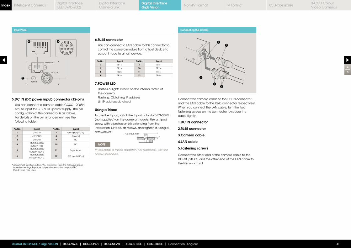
Rear Panel
5. DC IN (DC power input) connector (12-pin)
You can connect a camera cable CCXC-12P05N etc. to input the +12 V DC power supply. The pin configuration of this connector is as follows. For details on the pin arrangement, see the following table.
* About multi-function output. You can select from the following signals based on settings. Exposure output/strobe control outputs/GPO (fixed value Hi or Low).
Pin No. Signal Pin No. Signal
1 Ground 7 GPI input (ISO +)
2 +12 V DC 8 Ground
3 Ground 9 NC
4Multi-functionoutput* (TTL)
10 NC
5Multi-functionoutput* (ISO –)
11 Triger input
6Multi-function
output* (ISO +)12 GPI input (ISO –)
Pin No. Signal Pin No. Signal
1 TP1 + 9 TP3 –
2 TP1 – 10 TP2 –
3 TP2 + 11 TP4 +
4 TP3 + 12 TP4 –
6. RJ45 connector
You can connect a LAN cable to this connector to control the camera module from a host device to output image to a host device.
7. POWER LED
Flashes or lights based on the internal status of the camera. Flashing: Obtaining IP address Lit: IP address obtained
Using a Tripod
To use the tripod, install the tripod adaptor VCT-ST70I(not supplied) on the camera module. Use a tripod screw with a protrusion (4) extending from the installation surface, as follows, and tighten it, using a screwdriver.
NOTE
If you install a tripod adaptor (not supplied), use thescrews provided.
4
8
41DIGITAL INTERFACE / GigE VISION | XCG-V60E | XCG-SX97E | XCG-SX99E | XCG-U100E | XCG-5005E | Connection Diagram
4.5 to 5.5 mm
Connecting the Cables
Connect the camera cable to the DC IN connector and the LAN cable to the RJ45 connector respectively. When you connect the LAN cable, turn the two fastening screws on the connector to secure the cable tightly.
1.DC IN connector
2.RJ45 connector
3.Camera cable
4.LAN cable
5.Fastening screws
Connect the other end of the camera cable to theDC-700/700CE and the other end of the LAN cable tothe Network card.
Digital InterfaceGigE VisionIndex Digital Interface
IEEE1394b-2002Digital Interface Camera Link
Non-TV Format TV Format XC Accessories3-CCD Colour Video Cameras
Intelligent Cameras
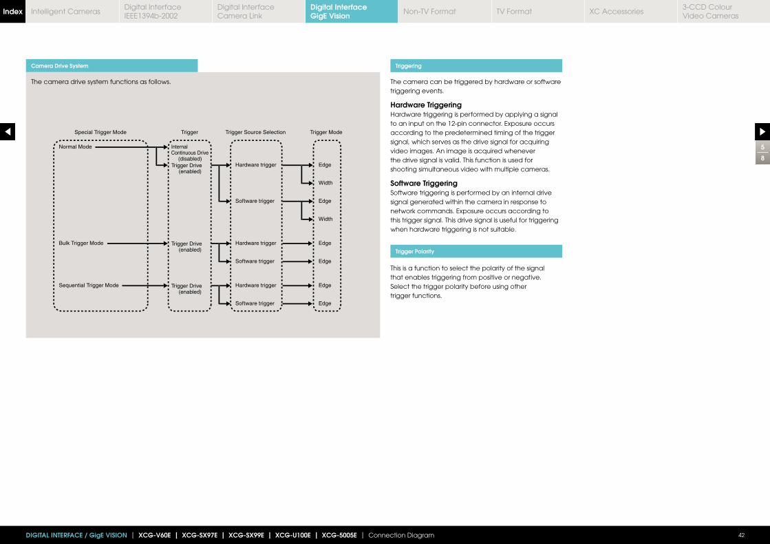
5
8
42DIGITAL INTERFACE / GigE VISION | XCG-V60E | XCG-SX97E | XCG-SX99E | XCG-U100E | XCG-5005E | Connection Diagram
Camera Drive System
The camera drive system functions as follows.
Triggering
Trigger Polarity
The camera can be triggered by hardware or softwaretriggering events.
Hardware TriggeringHardware triggering is performed by applying a signalto an input on the 12-pin connector. Exposure occurs according to the predetermined timing of the trigger signal, which serves as the drive signal for acquiring video images. An image is acquired wheneverthe drive signal is valid. This function is used forshooting simultaneous video with multiple cameras.
Software TriggeringSoftware triggering is performed by an internal drivesignal generated within the camera in response tonetwork commands. Exposure occurs according to this trigger signal. This drive signal is useful for triggeringwhen hardware triggering is not suitable.
This is a function to select the polarity of the signal that enables triggering from positive or negative.Select the trigger polarity before using other trigger functions.
Digital InterfaceGigE VisionIndex Digital Interface
IEEE1394b-2002Digital Interface Camera Link
Non-TV Format TV Format XC Accessories3-CCD Colour Video Cameras
Intelligent Cameras
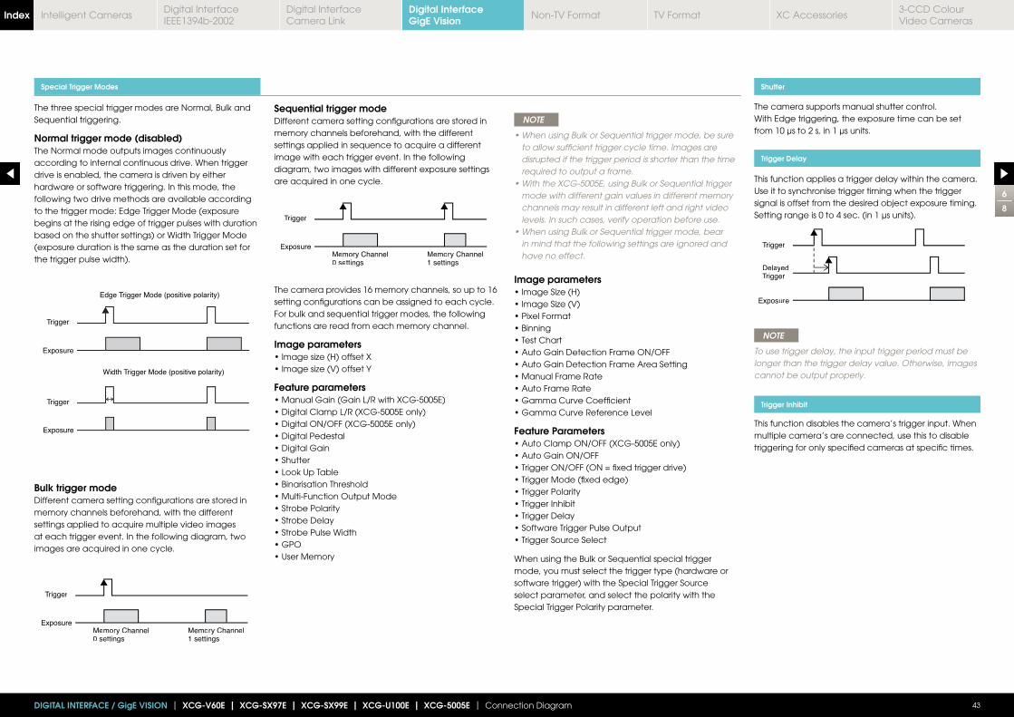
The three special trigger modes are Normal, Bulk andSequential triggering.
Normal trigger mode (disabled)The Normal mode outputs images continuouslyaccording to internal continuous drive. When triggerdrive is enabled, the camera is driven by either hardware or software triggering. In this mode, the following two drive methods are available according to the trigger mode: Edge Trigger Mode (exposure begins at the rising edge of trigger pulses with duration based on the shutter settings) or Width Trigger Mode (exposure duration is the same as the duration set for the trigger pulse width).
Bulk trigger modeDifferent camera setting configurations are stored inmemory channels beforehand, with the different settings applied to acquire multiple video images at each trigger event. In the following diagram, two images are acquired in one cycle.
Special Trigger Modes
Trigger
ExposureMemory Channel 0 settings
Memory Channel1 settings
NOTE
to allow sufficient trigger cycle time. Images are disrupted if the trigger period is shorter than the time required to output a frame.
mode with different gain values in different memory channels may result in different left and right video levels. In such cases, verify operation before use.
in mind that the following settings are ignored and have no effect.
Image parameters
Feature Parameters
When using the Bulk or Sequential special triggermode, you must select the trigger type (hardware orsoftware trigger) with the Special Trigger Sourceselect parameter, and select the polarity with theSpecial Trigger Polarity parameter.
Sequential trigger modeDifferent camera setting configurations are stored inmemory channels beforehand, with the different settings applied in sequence to acquire a different image with each trigger event. In the following diagram, two images with different exposure settings are acquired in one cycle.
The camera provides 16 memory channels, so up to 16setting configurations can be assigned to each cycle.For bulk and sequential trigger modes, the followingfunctions are read from each memory channel.
Image parameters
Feature parameters
6
8
43DIGITAL INTERFACE / GigE VISION | XCG-V60E | XCG-SX97E | XCG-SX99E | XCG-U100E | XCG-5005E | Connection Diagram
Trigger
ExposureMemory Channel0 settings
Memory Channel1 settings
The camera supports manual shutter control.With Edge triggering, the exposure time can be set from 10 μs to 2 s, in 1 μs units.
This function applies a trigger delay within the camera. Use it to synchronise trigger timing when the trigger signal is offset from the desired object exposure timing. Setting range is 0 to 4 sec. (in 1 μs units).
NOTE
To use trigger delay, the input trigger period must belonger than the trigger delay value. Otherwise, imagescannot be output properly.
This function disables the camera’s trigger input. When multiple camera’s are connected, use this to disable triggering for only specified cameras at specific times.
Shutter
Trigger Delay
Trigger Inhibit
Trigger
DelayedTrigger
Exposure
Digital InterfaceGigE VisionIndex Digital Interface
IEEE1394b-2002Digital Interface Camera Link
Non-TV Format TV Format XC Accessories3-CCD Colour Video Cameras
Intelligent Cameras
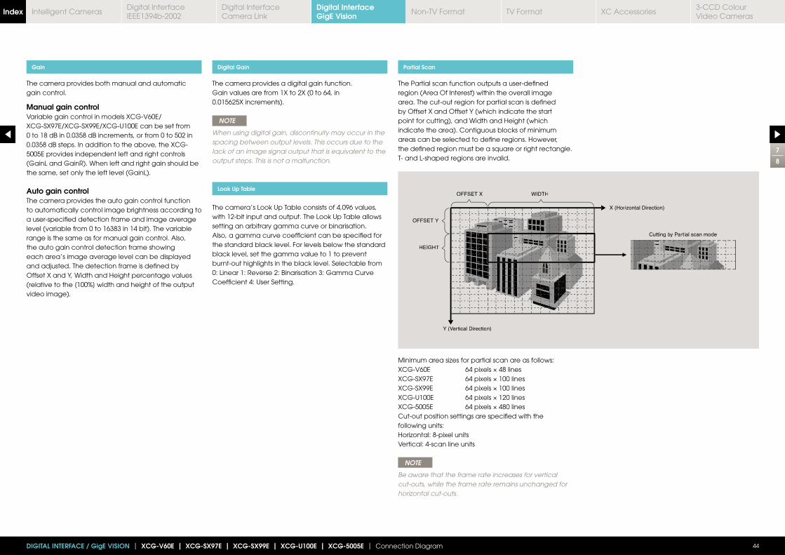
Gain
The camera provides both manual and automatic gain control.
Manual gain controlVariable gain control in models XCG-V60E/XCG-SX97E/XCG-SX99E/XCG-U100E can be set from 0 to 18 dB in 0.0358 dB increments, or from 0 to 502 in 0.0358 dB steps. In addition to the above, the XCG-5005E provides independent left and right controls (GainL and GainR). When left and right gain should be the same, set only the left level (GainL).
Auto gain controlThe camera provides the auto gain control function to automatically control image brightness according to a user-specified detection frame and image average level (variable from 0 to 16383 in 14 bit). The variable range is the same as for manual gain control. Also, the auto gain control detection frame showing each area’s image average level can be displayed and adjusted. The detection frame is defined by Offset X and Y, Width and Height percentage values (relative to the [100%] width and height of the output video image).
7
8
44DIGITAL INTERFACE / GigE VISION | XCG-V60E | XCG-SX97E | XCG-SX99E | XCG-U100E | XCG-5005E | Connection Diagram
The camera provides a digital gain function. Gain values are from 1X to 2X (0 to 64, in 0.015625X increments).
NOTE
When using digital gain, discontinuity may occur in thespacing between output levels. This occurs due to thelack of an image signal output that is equivalent to theoutput steps. This is not a malfunction.
The camera’s Look Up Table consists of 4,096 values,with 12-bit input and output. The Look Up Table allowssetting an arbitrary gamma curve or binarisation. Also, a gamma curve coefficient can be specified for the standard black level. For levels below the standard black level, set the gamma value to 1 to prevent burnt-out highlights in the black level. Selectable from 0: Linear 1: Reverse 2: Binarisation 3: Gamma Curve Coefficient 4: User Setting.
The Partial scan function outputs a user-defined region (Area Of Interest) within the overall image area. The cut-out region for partial scan is defined by Offset X and Offset Y (which indicate the start point for cutting), and Width and Height (which indicate the area). Contiguous blocks of minimum areas can be selected to define regions. However, the defined region must be a square or right rectangle. T- and L-shaped regions are invalid.
Cut-out position settings are specified with the following units:
Vertical: 4-scan line units
NOTE
Be aware that the frame rate increases for vertical cut-outs, while the frame rate remains unchanged for horizontal cut-outs.
Digital Gain
Look Up Table
Partial Scan
OFFSET X
OFFSET Y
WIDTH
HEIGHT
Y (VerVV tical Direction)
X (Horizontal Direction)
Cutting by Partial scan mode
Digital InterfaceGigE VisionIndex Digital Interface
IEEE1394b-2002Digital Interface Camera Link
Non-TV Format TV Format XC Accessories3-CCD Colour Video Cameras
Intelligent Cameras
8
8
45DIGITAL INTERFACE / GigE VISION | XCG-V60E | XCG-SX97E | XCG-SX99E | XCG-U100E | XCG-5005E | Connection Diagram
Binning Mode Image Acquisition Modes
The following three image acquisition modes areavailable:
(from 1 to 255)
Memory channelsSixteen memory channels are provided for cameraparameters that can be switched at each frame when using bulk and sequential trigger modes. The memory channels can also be used to store user settings when the special trigger mode is set to Normal, to be applied when switching the camera state for particular situations.
User MemoriesEach memory channel provides 64 bytes of non-volatile read-write storage for users to store data freely.Stored data is preserved even when the power is turned off.
This mode increases sensitivity and frame rate by combining vertically adjacent pixel data from the CCD.
NOTE
Binning mode approximately doubles sensitivity by combining vertical signals on alternate pairs of adjacent lines. However, because the frame rate is also doubled, available exposure time that is consequently halved. Setting a shorter exposure time enhances the effect, and sensitivity is further increased. Consider the effect on exposure time when using the Binning mode.
Memory Channels and User Memories
Digital InterfaceGigE VisionIndex Digital Interface
IEEE1394b-2002Digital Interface Camera Link
Non-TV Format TV Format XC Accessories3-CCD Colour Video Cameras
Intelligent Cameras
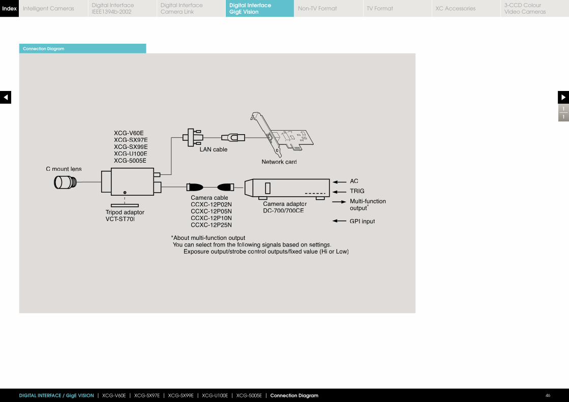
46DIGITAL INTERFACE / GigE VISION | XCG-V60E | XCG-SX97E | XCG-SX99E | XCG-U100E | XCG-5005E | Connection Diagram
Connection Diagram
C mmount lens
Tripod adaptorVCT-ST70I
Camera cableCCXC-12P02NCCXC-12P05NCCXC-12P10NCCXC-12P25N
Camera adaptorDC-700/700CE
AC
TRIG
LAN cable
Network card
XCG-V60EXCG-SX97EXCG-SX99EXCG-U100EXCG-5005E
*About multi-function outputYou can select from the following signals based on settings.
Exposure output/strobe control outputs/fi// xed value (Hi or Low)
Multi-functionoutput*
GPI input
1
1
Digital InterfaceGigE VisionIndex Digital Interface
IEEE1394b-2002Digital Interface Camera Link
Non-TV Format TV Format XC Accessories3-CCD Colour Video Cameras
Intelligent Cameras
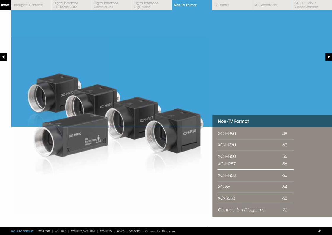
Non-TV Format
XC-HR90 48
XC-HR70 52
XC-HR50 56
XC-HR57 56
XC-HR58 60
XC-56 64
XC-56BB 68
Connection Diagrams 72
NON-TV FORMAT | XC-HR90 | XC-HR70 | XC-HR50/XC-HR57 | XC-HR58 | XC-56 | XC-56BB | Connection Diagrams 47
Non-TV FormatIndex Digital Interface IEEE1394b-2002
Digital Interface Camera Link
Digital InterfaceGigE Vision
TV Format XC Accessories3-CCD Colour Video Cameras
Intelligent Cameras
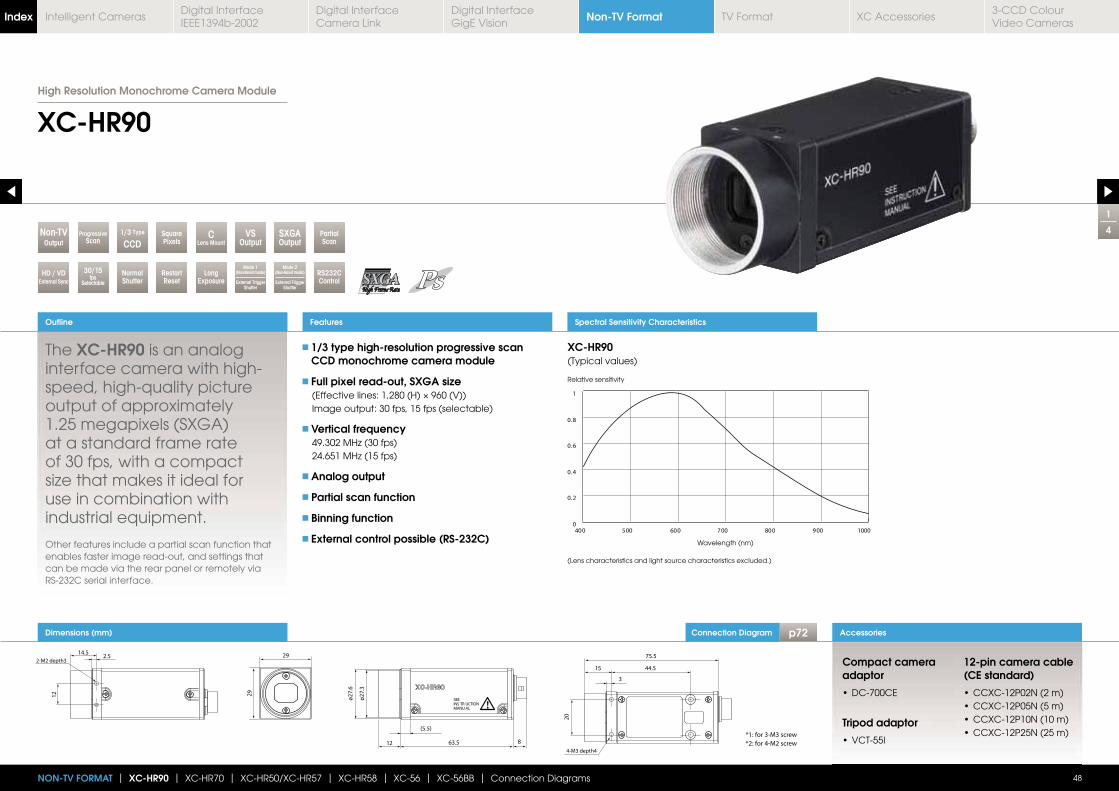
Connection Diagram p72Dimensions (mm)
1
4
XC-HR90
The XC-HR90 is an analog interface camera with high-speed, high-quality picture output of approximately 1.25 megapixels (SXGA) at a standard frame rate of 30 fps, with a compact
use in combination with industrial equipment.
Other features include a partial scan function that enables faster image read-out, and settings that can be made via the rear panel or remotely via RS-232C serial interface.
1/3 type high-resolution progressive scan CCD monochrome camera module
Full pixel read-out, SXGA size
Image output: 30 fps, 15 fps (selectable)
Vertical frequency
Analog output
Partial scan function
Binning function
External control possible (RS-232C)
Outline
48
Accessories
Features Spectral Sensitivity Characteristics
Compact camera adaptor
Tripod adaptor
12-pin camera cable (CE standard)
NON-TV FORMAT | XC-HR90 | XC-HR70 | XC-HR50/XC-HR57 | XC-HR58 | XC-56 | XC-56BB | Connection Diagrams
RestartReset
1/3 Type
CCDPartialScan
SquarePixels
CLens MountOutput
Non-TV
Mode 2(Non-Reset mode)
External Trigger Shutter
LongExposure
30/15fps
Selectable
NormalShutter
Mode 1(Non-Reset mode)
External Trigger Shutter
VSOutput
SXGAOutput
ProgressiveScan
RS232CControl
HD / VDExternal Sync
XC-HR90(Typical values)
Relative sensitivity
Wavelength (nm)
(Lens characteristics and light source characteristics excluded.)
High Resolution Monochrome Camera Module
Non-TV FormatIndex Digital Interface IEEE1394b-2002
Digital Interface Camera Link
Digital InterfaceGigE Vision
TV Format XC Accessories3-CCD Colour Video Cameras
Intelligent Cameras
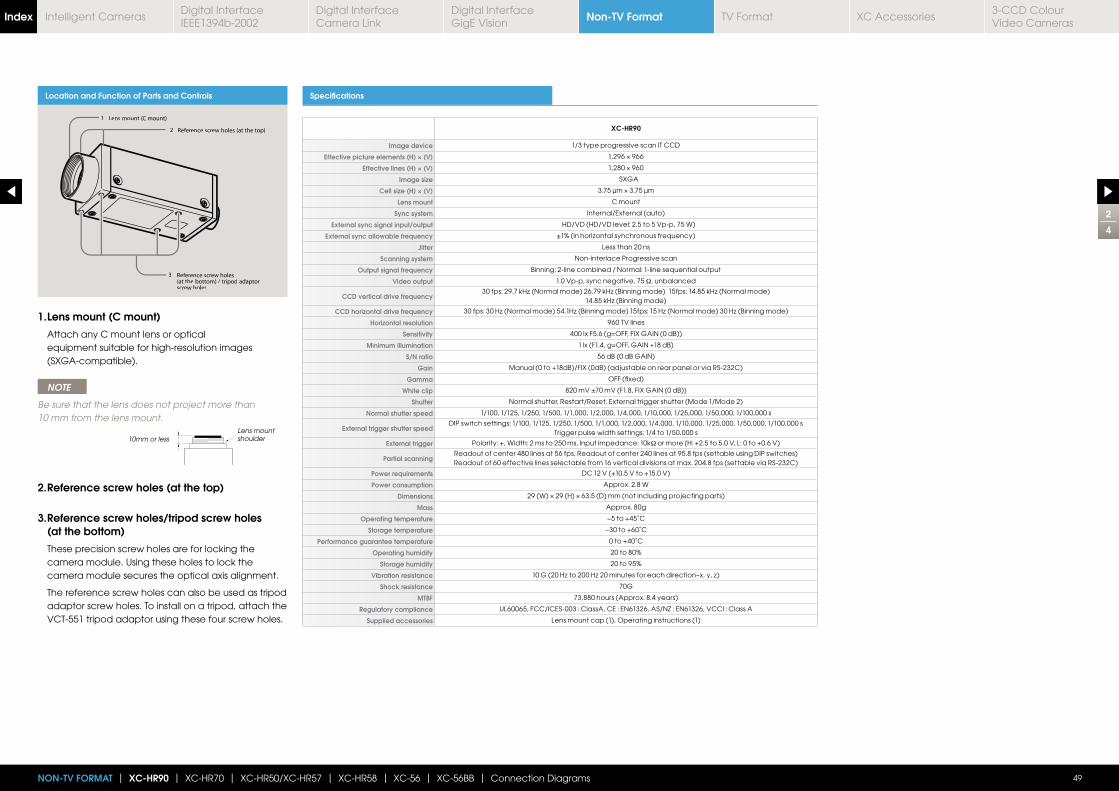
Location and Function of Parts and Controls Specifications
XC-HR90
Image device 1/3 type progressive scan IT CCD
Effective picture elements (H) × (V)
Effective lines (H) × (V)
Image size SXGA
Cell size (H) × (V)
Lens mount C mount
Sync system Internal/External (auto)
External sync signal input/output HD/VD (HD/VD level: 2.5 to 5 Vp-p, 75 W)
External sync allowable frequency
Jitter Less than 20 ns
Scanning system Non-interlace Progressive scan
Output signal frequency Binning: 2-line combined / Normal: 1-line sequential output
Video output 1.0 Vp-p, sync negative, 75 Ω, unbalanced
CCD vertical drive frequency
CCD horizontal drive frequency
Horizontal resolution 960 TV lines
Sensitivity
Minimum illumination
S/N ratio 56 dB (0 dB GAIN)
Gain Manual (0 to +18dB)/FIX (0dB) (adjustable on rear panel or via RS-232C)
Gamma OFF (fixed)
White clip 820 mV ±70 mV (F1.8, FIX GAIN (0 dB))
Shutter Normal shutter, Restart/Reset, External trigger shutter (Mode 1/Mode 2)
Normal shutter speed 1/100, 1/125, 1/250, 1/500, 1/1,000, 1/2,000, 1/4,000, 1/10,000, 1/25,000, 1/50,000, 1/100,000 s
External trigger shutter speedDIP switch settings: 1/100, 1/125, 1/250, 1/500, 1/1,000, 1/2,000, 1/4,000, 1/10,000, 1/25,000, 1/50,000, 1/100,000 s
Trigger pulse width settings: 1/4 to 1/50,000 s
External trigger Polarity: +, Width: 2 ms to 250 ms, Input impedance: 10kΩ or more (H: +2.5 to 5.0 V, L: 0 to +0.6 V)
Partial scanningReadout of center 480 lines at 56 fps, Readout of center 240 lines at 95.8 fps (settable using DIP switches) Readout of 60 effective lines selectable from 16 vertical divisions at max. 204.8 fps (settable via RS-232C)
Power requirements DC 12 V (+10.5 V to +15.0 V)
Power consumption Approx. 2.8 W
Dimensions
Mass Approx. 80g
Operating temperature −5 to +45˚C
Storage temperature −30 to +60˚C
Performance guarantee temperature 0 to +40˚C
Operating humidity 20 to 80%
Storage humidity 20 to 95%
Vibration resistance
Shock resistance 70G
MTBF 73,880 hours (Approx. 8.4 years)
Regulatory compliance UL60065, FCC/ICES-003 : ClassA, CE : EN61326, AS/NZ : EN61326, VCCI : Class A
Supplied accessories Lens mount cap (1), Operating instructions (1)
2
4
49NON-TV FORMAT | XC-HR90 | XC-HR70 | XC-HR50/XC-HR57 | XC-HR58 | XC-56 | XC-56BB | Connection Diagrams
1 Lens mount (C mount)
2 Reference screw holes (at the top)
3 Reference screw holes (at the bottom) / tripod adaptorscrew holes
1. Lens mount (C mount)
Attach any C mount lens or optical equipment suitable for high-resolution images (SXGA-compatible).
NOTE
Be sure that the lens does not project more than 10 mm from the lens mount.
2. Reference screw holes (at the top)
3. Reference screw holes/tripod screw holes (at the bottom)
These precision screw holes are for locking the camera module. Using these holes to lock the camera module secures the optical axis alignment.
The reference screw holes can also be used as tripod adaptor screw holes. To install on a tripod, attach the VCT-551 tripod adaptor using these four screw holes.
10mm or lessLens mount shoulder
Non-TV FormatIndex Digital Interface IEEE1394b-2002
Digital Interface Camera Link
Digital InterfaceGigE Vision
TV Format XC Accessories3-CCD Colour Video Cameras
Intelligent Cameras
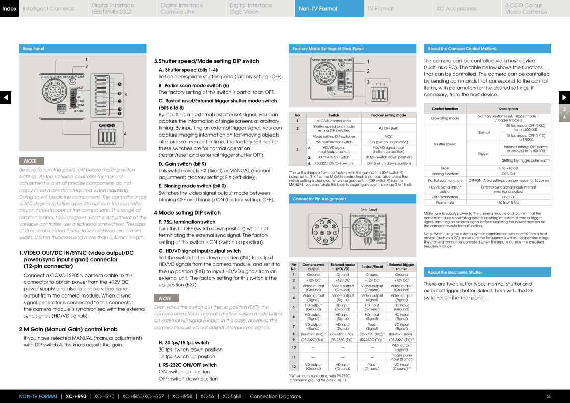
Rear Panel
Rear Panel Factory Mode Settings of Rear Panel
Connector Pin Assignments
About the Camera Control Method
AAA
BB
CCC
DDDDEE
FF GG HH II
NOTE
Be sure to turn the power off before making switch settings. As the variable controller for manual adjustment is a small precise component, do not apply force more than required when adjusting. Doing so will break the component. The controller is not a 360-degree rotation type. Do not turn the controller beyond the stopper of the component. The range of rotation is about 230 degrees. For the adjustment of the variable controller, use a flathead screwdriver. The sizes of a recommended flathead screwdrivers are 1.9mm width, 0.5mm thickness and more than 0.45mm length.
1. VIDEO OUT/DC IN/SYNC (video output/DC power/sync input signal) connector (12-pin connector)
Connect a CCXC-12P05N camera cable to this connector to obtain power from the +12V DC power supply and also to enable video signal output from the camera module. When a sync signal generator is connected to this connector, the camera module is synchronised with the external sync signals (HD/VD signals).
2. M Gain (Manual Gain) control knob
If you have selected MANUAL (manual adjustment) with DIP switch 4, this knob adjusts the gain.
No. Switch Factory setting mode
1 M GAIN control knob — *
2 Shutter speed and mode setting DIP switches
All OFF (left)
3
Mode setting DIP switches VCC
75Ω termination switch ON (switch up position)
HD/VD signal input/output switch
HD/VD signal input (switch up position)
30 fps/15 fps switch 30 fps (switch down position)
RS-232C ON/OFF switch OFF (switch down position)
Pin No.
Camera sync output
External mode (HD/VD) Restart/Reset External trigger
shutter
1 Ground Ground Ground Ground
2 +12V DC +12V DC +12V DC +12V DC
3 Video output (Ground)
Video output (Ground)
Video output (Ground)
Video output (Ground)
4 Video output (Signal)
Video output (Signal)
Video output (Signal)
Video output (Signal)
5 HD output (Ground)
HD input (Ground)
HD input (Ground)
HD input (Ground)
6 HD output (Signal)
HD input(Signal)
HD input(Signal)
HD input(Signal)
7 VD output (Signal)
VD input(Signal)
Reset(Signal)
VD input(Signal)
8 (RS-232C (Rx)) *1 (RS-232C (Rx)) *1 (RS-232C (Rx)) *1 (RS-232C (Rx)) *1
9 (RS-232C (Tx)) *1 (RS-232C (Tx)) *1 (RS-232C (Tx)) *1 (RS-232C (Tx)) *1
10 — — —WEN output
(Signal)
11 — — —Trigger pulse input (Signal)
12 VD output (Ground)
VD input (Ground)
Reset(Ground)
VD input (Ground) *2
Control function Description
Operating modeNormal/ Restart reset/ Trigger mode 1
/ Trigger mode 2
Shutter speed
Normal
30 fps mode: OFF (1/30) to 1/1,000,000
15 fps mode: OFF (1/15) to 1/5000
Trigger
Internal setting: OFF (same as above) to 1/100,000
Setting by trigger pulse width
Gain 0 to +18 dB
Binning function OFF/ON
Partial scan function
HD/VD signal input/output
External sync signal input/Internal sync signal output
75Ω termination ON/OFF
Frame rate 30 fps/15 fps
3
4
50NON-TV FORMAT | XC-HR90 | XC-HR70 | XC-HR50/XC-HR57 | XC-HR58 | XC-56 | XC-56BB | Connection Diagrams
3. Shutter speed/Mode setting DIP switch
A. Shutter speed (bits 1-4) Set an appropriate shutter speed (factory setting: OFF).
B. Partial scan mode switch (5) The factory setting of this switch is partial scan OFF.
C. Restart reset/External trigger shutter mode switch (bits 6 to 8)
By inputting an external restart/reset signal, you can capture the information of single screens at arbitrary timing. By inputting an external trigger signal, you can capture imaging information on fast-moving objects at a precise moment in time. The factory settings for these switches are for normal operation
(restart/reset and external trigger shutter OFF).
D. Gain switch (bit 9) This switch selects FIX (fixed) or MANUAL (manual
adjustment) (factory setting: FIX (left side)).
E. Binning mode switch (bit 0) Switches the video signal output mode between
binning OFF and binning ON (factory setting: OFF).
4 Mode setting DIP switch
F. 75Ω termination switch Turn this to OFF (switch down position) when not
terminating the external sync signal. The factory setting of this switch is ON (switch up position).
G. HD/VD signal input/output switch Set the switch to the down position (INT) to output
HD/VD signals from the camera module, and set it to the up position (EXT) to input HD/VD signals from an external unit. The factory setting for this switch is the up position (EXT).
NOTE
Even when the switch is in the up position (EXT), the camera operates in internal synchronisation mode unless an external HD signal is input. In this case, however, the camera module will not output internal sync signals.
H. 30 fps/15 fps switch 30 fps: switch down position 15 fps: switch up position
I. RS-232C ON/OFF switch ON: switch up position OFF: switch down position
This camera can be controlled via a host device (such as a PC). The table below shows the functions that can be controlled. The camera can be controlled by sending commands that correspond to the control items, with parameters for the desired settings, if necessary, from the host device.
1.
2.
3.
4.
*This unit is shipped from the factory with the gain switch (DIP switch 9) being set to “FIX,” so the M GAIN control knob is not operative unless the switch setting is changed. When the gain switch (DIP switch 9) is set to MANUAL, you can rotate this knob to adjust gain over the range 0 to 18 dB.
Make sure to supply power to the camera module and confirm that the camera module is operating before inputting an external sync or trigger signal. Inputting an external signal before supplying the power may cause the camera module to malfunction.
Note: When using the external sync in combination with control from a host device (such as a PC), make sure the frequency is within the specified range. The camera cannot be controlled when the input is outside the specified frequency range.
*1 When communicating with RS-232C.*2 Common ground for pins 7, 10, 11.
About the Electronic Shutter
There are two shutter types: normal shutter and external trigger shutter. Select them with the DIP switches on the rear panel.
Non-TV FormatIndex Digital Interface IEEE1394b-2002
Digital Interface Camera Link
Digital InterfaceGigE Vision
TV Format XC Accessories3-CCD Colour Video Cameras
Intelligent Cameras
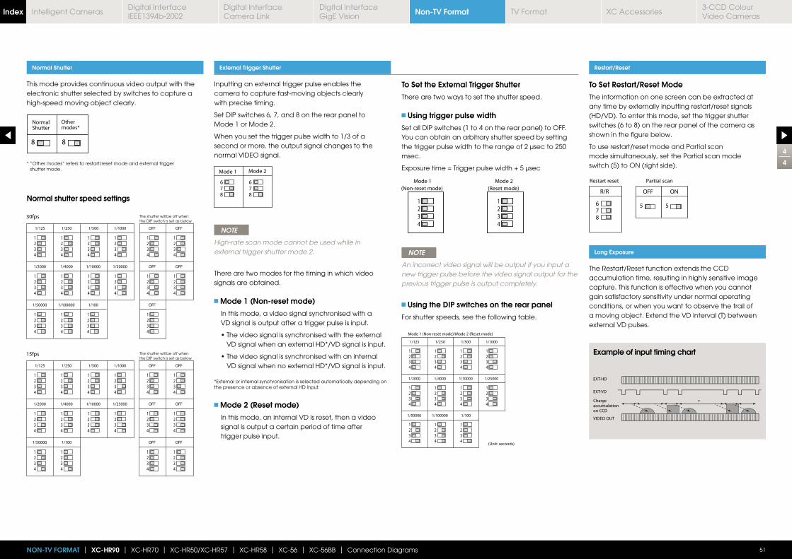
Inputting an external trigger pulse enables the camera to capture fast-moving objects clearly with precise timing.
Set DIP switches 6, 7, and 8 on the rear panel to Mode 1 or Mode 2.
When you set the trigger pulse width to 1/3 of a second or more, the output signal changes to the normal VIDEO signal.
NOTE
High-rate scan mode cannot be used while in external trigger shutter mode 2.
There are two modes for the timing in which video signals are obtained.
Mode 1 (Non-reset mode)
In this mode, a video signal synchronised with a VD signal is output after a trigger pulse is input.
VD signal when an external HD*/VD signal is input.
VD signal when no external HD*/VD signal is input.
*External or internal synchronisation is selected automatically depending on the presence or absence of external HD input.
Mode 2 (Reset mode)
In this mode, an internal VD is reset, then a video signal is output a certain period of time after trigger pulse input.
To Set the External Trigger Shutter
There are two ways to set the shutter speed.
Using trigger pulse width
Set all DIP switches (1 to 4 on the rear panel) to OFF.You can obtain an arbitrary shutter speed by setting the trigger pulse width to the range of 2 μsec to 250 msec.
NOTE
An incorrect video signal will be output if you input a new trigger pulse before the video signal output for the previous trigger pulse is output completely.
Using the DIP switches on the rear panel
For shutter speeds, see the following table.
This mode provides continuous video output with the electronic shutter selected by switches to capture a high-speed moving object clearly.
Normal Shutter External Trigger Shutter
4
4
51NON-TV FORMAT | XC-HR90 | XC-HR70 | XC-HR50/XC-HR57 | XC-HR58 | XC-56 | XC-56BB | Connection Diagrams
* “Other modes” refers to restart/reset mode and external trigger shutter mode.
Normal shutter speed settings
The shutter will be off when the DIP switch is set as below
The shutter will be off when the DIP switch is set as below
Restart/Reset
Long Exposure
To Set Restart/Reset Mode
The information on one screen can be extracted at any time by externally inputting restart/reset signals (HD/VD). To enter this mode, set the trigger shutter switches (6 to 8) on the rear panel of the camera as shown in the figure below.
To use restart/reset mode and Partial scan mode simultaneously, set the Partial scan mode switch (5) to ON (right side).
The Restart/Reset function extends the CCD accumulation time, resulting in highly sensitive image capture. This function is effective when you cannot gain satisfactory sensitivity under normal operating conditions, or when you want to observe the trail of a moving object. Extend the VD interval (T) between external VD pulses.
Example of input timing chart
Non-TV FormatIndex Digital Interface IEEE1394b-2002
Digital Interface Camera Link
Digital InterfaceGigE Vision
TV Format XC Accessories3-CCD Colour Video Cameras
Intelligent Cameras
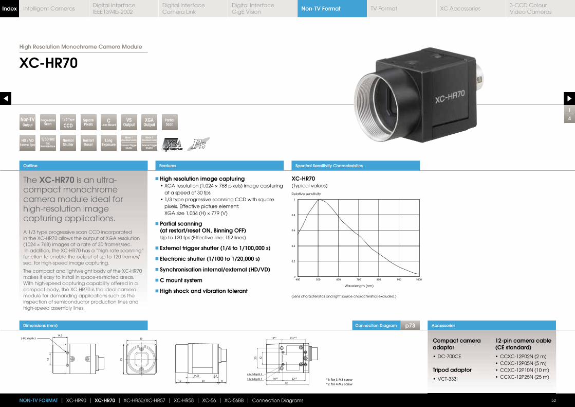
Connection Diagram p73
0
0.2
0.4
0.6
0.8
1
400 500 600 700 800 900 1000
Spectral Sensitivity Characteristics
XC-HR70(Typical values)
Relative sensitivity
Wavelength (nm)
(Lens characteristics and light source characteristics excluded.)
Dimensions (mm)
1
4
XC-HR70
The XC-HR70 is an ultra-compact monochrome camera module ideal for high-resolution image capturing applications.
High resolution image capturing
at a speed of 30 fps
pixels. Effective picture element:
Partial scanning (at restart/reset ON, Binning OFF)
Up to 120 fps (Effective line: 152 lines)
External trigger shutter (1/4 to 1/100,000 s)
Electronic shutter (1/100 to 1/20,000 s)
Synchronisation internal/external (HD/VD)
C mount system
High shock and vibration tolerant
Outline
52
Accessories
Features
NON-TV FORMAT | XC-HR90 | XC-HR70 | XC-HR50/XC-HR57 | XC-HR58 | XC-56 | XC-56BB | Connection Diagrams
RestartReset
PartialScan
SquarePixels
LongExposure
1/30 sec1N:
Non-interface
NormalShutter
VSOutput
XGAOutput
ProgressiveScan
1/3 Type
CCDC
Lens MountOutputNon-TV
Mode 2(Non-Reset mode)
External Trigger Shutter
HD / VDExternal Sync
Mode 1(Non-Reset mode)
External Trigger Shutter
A 1/3 type progressive scan CCD incorporated in the XC-HR70 allows the output of XGA resolution
In addition, the XC-HR70 has a “high rate scanning” function to enable the output of up to 120 frames/sec. for high-speed image capturing.
The compact and lightweight body of the XC-HR70 makes it easy to install in space-restricted areas. With high-speed capturing capability offered in a compact body, the XC-HR70 is the ideal camera module for demanding applications such as the inspection of semiconductor production lines and high-speed assembly lines.
Compact camera adaptor
Tripod adaptor
12-pin camera cable (CE standard)
29
29
14.5
12
2-M2 depth 3
12 30 8
(4.9) 5.1
Ø27
.6
0.15
Ø27
.3
0.15
15*1 23.7* 1
20 12
3-M3 depth 3
42
4-M2 depth 3
16*2 22*2*1: for 3-M3 screw
*2: for 4-M2 screw
High Resolution Monochrome Camera Module
Non-TV FormatIndex Digital Interface IEEE1394b-2002
Digital Interface Camera Link
Digital InterfaceGigE Vision
TV Format XC Accessories3-CCD Colour Video Cameras
Intelligent Cameras
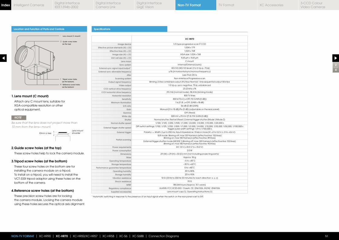
2
4
53NON-TV FORMAT | XC-HR90 | XC-HR70 | XC-HR50/XC-HR57 | XC-HR58 | XC-56 | XC-56BB | Connection Diagrams
Location and Function of Parts and Controls Specifications
XC-HR70
Image device 1/3 type progressive scan IT CCD
Effective picture elements (H) × (V)
Effective lines (H) × (V)
Image size (H) × (V)
Unit cell size (H) × (V)
Lens moun C mount
Sync system Internal/External (auto)
External sync signal input/output*1 HD/VD (HD/VD level: 2 to 5 Vp-p, 75 Ω)
External sync allowable frequency
Jitter Less than 20 ns
Scanning system Non-interlace Progressive scan
Output signal frequency Binning: 2-line combined output 29.2 fps/ Normal: 1-line sequential output 58.4 fps
Video output 1.0 Vp-p, sync negative, 75 Ω, unbalanced
CCD vertical drive frequency
CCD horizontal drive frequency
Horizontal resolution 800 TV lines
Sensitivity 400 lx F5.6 (γ
Minimum illumination 1 lx (F1.8, γ
S/N ratio 56 dB (0 dB GAIN)
Gain Manual (0 to 18 dB)/Fix (0 dB) (adjustable on the rear panel)
Gamma OFF (fixed)
White clip 820 mV ±70 mV (F1.8, FIX GAIN (0 dB))
Shutter Normal shutter, Restart/Reset, External trigger shutter (Mode 1/Mode 2)
Normal shutter speed 1/100, 1/125, 1/250, 1/500, 1/1,000, 1/2,000, 1/4,000, 1/10,000, 1/20,000 s
External trigger shutter speedDIP switch settings: 1/100, 1/125, 1/250, 1/500, 1/1,000, 1/2,000, 1/4,000, 1/10,000, 1/25,000, 1/50,000, 1/100,000 s
Trigger pulse width settings: 1/4 to 1/100,000 s
External trigger Polarity: +, Width: 2 μs to 250 ms, Input impedance: 10 kΩ or more (H: +2 to 5.0 V, L: 0 to +0.6 V)
Partial scanning
R/R mode Binning off: max 120 frames/s (effective line: 152 lines)Binning on: max 180 frames/s (effective line: 89 lines)
External trigger shutter mode (MODE 1) Binning off: max 120 frames/s (effective line: 153 lines)Binning on: max 180 frames/s (effective line: 90 lines)
Power requirements DC 12 V (+10.5 V to +15.0 V)
Power consumption 2.0 W
Dimensions
Mass Approx. 50 g
Operating temperature −5 to +45˚C
Storage temperature −30 to +60˚C
Performance guarantee temperature 0 to +40˚C
Operating humidity 20 to 80%
Storage humidity 20 to 95%
Vibration resistance
Shock resistance 70 G
MTBF 88,044 hours (Approx. 10.1 years)
Regulatory compliance UL6500, FCC/ICES-003 : ClassA, CE : EN61326, AS/NZ : EN61326
Supplied accessories Lens mount cap (1), Operating instructions (1)
1 Lens mount (C mount)
2 Guide screw holes
(at the top)
3 Tripod screw holes
(at the bottom)
4 Reference screw holes
(at the bottom)
1. Lens mount (C mount)
Attach any C mount lens, suitable for XGA-compatible resolution or other optical equipment.
NOTE
Be sure that the lens does not project more than 10 mm from the lens= mount.
2. Guide screw holes (at the top)
These screw holes help to lock the camera module.
3. Tripod screw holes (at the bottom)
These four screw holes on the bottom are for installing the camera module on a tripod. To install on a tripod, you will need to install the VCT-333I tripod adaptor using these holes on the bottom of the camera.
4. Reference screw holes (at the bottom)
These precision screw holes are for locking the camera module. Locking the camera module using these holes secures the optical axis alignment.
10mm or lessLens mount shoulder
*1 Automatic switching in response to the presence of an input signal when the switch on the rear panel is set to EXT.
Non-TV FormatIndex Digital Interface IEEE1394b-2002
Digital Interface Camera Link
Digital InterfaceGigE Vision
TV Format XC Accessories3-CCD Colour Video Cameras
Intelligent Cameras
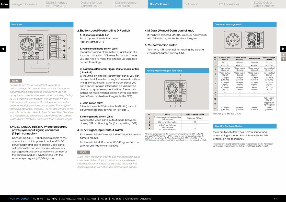
3
4
54NON-TV FORMAT | XC-HR90 | XC-HR70 | XC-HR50/XC-HR57 | XC-HR58 | XC-56 | XC-56BB | Connection Diagrams
Rear Panel
Factory Mode Settings of Rear Panel
2
1
3
4
5
AA
BB
DDDEE
CC
NOTE
Be sure to turn the power off before making switch settings. As the variable controller for manual adjustment is a small precise component, do not apply force more than required when adjusting. Doing so will break the component. The controller is not a 360-degree rotation type. Do not turn the controller beyond the stopper of the component. The range of rotation is about 260 degrees. For the adjustment of the variable controller, use a flathead screwdriver. The sizes of a recommended flathead screwdrivers are 1.9mm width, 0.5mm thickness and more than 0.45mm length.
1. VIDEO OUT/DC IN/SYNC (video output/DC power/sync input signal) connector (12-pin connector)
Connect a CCXC-12P05N camera cable to this connector to obtain power from the +12V DC power supply and also to enable video signal output from the camera module. When a sync signal generator is connected to this connector, the camera module is synchronised with the external sync signals (HD/VD signals).
No. Switch Factory setting mode
1 Shutter speed and mode setting DIP switches
All bits are OFF (left)
2 75Ω termination switch ON
3 M GAIN control knob — *
4 HD/VD signal input/output switch
EXT
2. Shutter speed/Mode setting DIP switch
A. Shutter speed (bits 1-4) Set an appropriate shutter speed
(factory setting: OFF).
B. Partial scan mode switch (bit 5) The factory setting of this switch is Partial scan OFF.
If you turn this switch ON to use Partial scan mode, you also need to make the external VD pulse rate and width settings.
C. Restart reset/External trigger shutter mode switch (bits 6 to 8)
By inputting an external restart/reset signal, you can capture the information of single screens at arbitrary timing. By inputting an external trigger signal, you can capture imaging information on fast-moving objects at a precise moment in time. The factory settings for these switches are for normal operation (restart/reset and external trigger shutter OFF).
D. Gain switch (bit 9) This switch selects FIX (fixed) or MANUAL (manual
adjustment) (factory setting: FIX (left side)).
E. Binning mode switch (bit 0) Switches the video signal output mode between
binning OFF and binning ON (factory setting: OFF).
3. HD/VD signal input/output switch
Set the switch to INT to output HD/VD signals from the camera module.
Set the switch to EXT to input HD/VD signals from an external unit (factory setting: EXT).
NOTE:
Even when the switch is set to EXT, the camera module operates in internal synchronisation mode when no external HD signal is input. In this case, however, the camera module will not output internal sync signals.
4. M Gain (Manual Gain) control knob
If you have selected MANUAL (manual adjustment) with DIP switch 4, this knob adjusts the gain.
5. 75Ω termination switch
Turn this to OFF when not terminating the external sync signal (factory setting: ON).
* This unit is shipped from the factory with the gain switch (DIP switch 9) being set to “FIX,” so the M GAIN control knob is not operative unless the switch setting is changed. When the gain switch (DIP switch 9) is set to MANUAL, you can rotate this knob to adjust gain over the range 0 to 18 dB.
Connector Pin Assignments
Pin No.
Camera sync output
External mode (HD/VD) Restart/Reset External trigger
shutter
1 Ground Ground Ground Ground
2 +12V DC +12V DC +12V DC +12V DC
3 Video output (Ground)
Video output (Ground)
Video output 1 (Ground)
Video output (Ground)
4 Video output (Signal)
Video output (Signal)
Video output 1 (Signal)
Video output (Signal)
5 HD output (Ground)
HD input (Ground)
HD input (Ground)
HD input (Ground)
6 HD output (Signal)
HD input(Signal)
HD input(Signal)
HD input(Signal)
7 VD output (Signal)
VD input(Signal)
Reset(Signal)
VD input(Signal)
8 — — — —
9 — — — —
10 — —WEN output
(Signal)
11 — — —Trigger pulse input (Signal)
12 VD output (Ground)
VD input (Ground)
Reset(Ground)
Reset(Ground)*
* Common ground for pins 7, 10, 11.
About the Electronic Shutter
There are two shutter types: normal shutter and external trigger shutter. Select them with the DIP switches on the rear panel.
* The electronic shutter cannot be used in restart/reset mode. Partial scan can be used in restart/reset mode in external trigger shutter mode1.
Non-TV FormatIndex Digital Interface IEEE1394b-2002
Digital Interface Camera Link
Digital InterfaceGigE Vision
TV Format XC Accessories3-CCD Colour Video Cameras
Intelligent Cameras
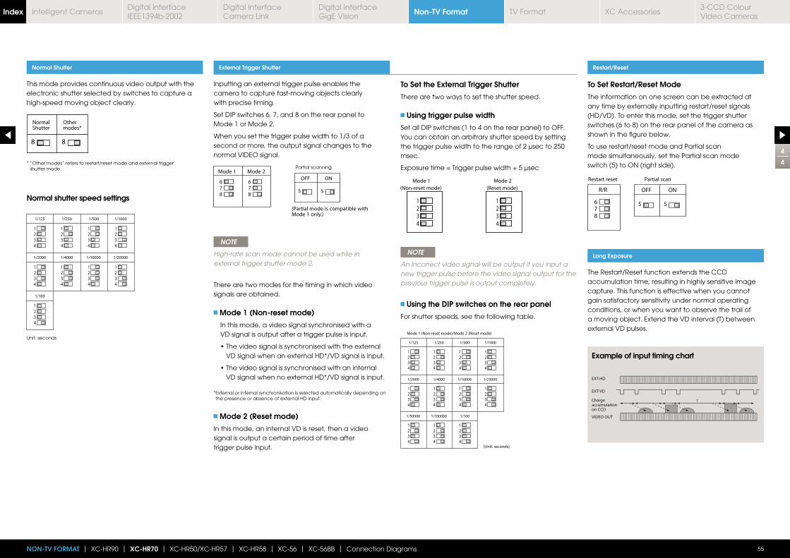
4
4
55NON-TV FORMAT | XC-HR90 | XC-HR70 | XC-HR50/XC-HR57 | XC-HR58 | XC-56 | XC-56BB | Connection Diagrams
Inputting an external trigger pulse enables the camera to capture fast-moving objects clearly with precise timing.
Set DIP switches 6, 7, and 8 on the rear panel to Mode 1 or Mode 2.
When you set the trigger pulse width to 1/3 of a second or more, the output signal changes to the normal VIDEO signal.
NOTE
High-rate scan mode cannot be used while in external trigger shutter mode 2.
There are two modes for the timing in which video signals are obtained.
Mode 1 (Non-reset mode)
In this mode, a video signal synchronised with a VD signal is output after a trigger pulse is input.
VD signal when an external HD*/VD signal is input.
VD signal when no external HD*/VD signal is input.
* External or internal synchronisation is selected automatically depending on the presence or absence of external HD input.
Mode 2 (Reset mode)
In this mode, an internal VD is reset, then a video signal is output a certain period of time after trigger pulse input.
To Set the External Trigger Shutter
There are two ways to set the shutter speed.
Using trigger pulse width
Set all DIP switches (1 to 4 on the rear panel) to OFF.You can obtain an arbitrary shutter speed by setting the trigger pulse width to the range of 2 μsec to 250 msec.
NOTE
An incorrect video signal will be output if you input a new trigger pulse before the video signal output for the previous trigger pulse is output completely.
Using the DIP switches on the rear panel
For shutter speeds, see the following table.
This mode provides continuous video output with the electronic shutter selected by switches to capture a high-speed moving object clearly.
Normal Shutter External Trigger Shutter Restart/Reset
Long Exposure
To Set Restart/Reset Mode
The information on one screen can be extracted at any time by externally inputting restart/reset signals (HD/VD). To enter this mode, set the trigger shutter switches (6 to 8) on the rear panel of the camera as shown in the figure below.
To use restart/reset mode and Partial scan mode simultaneously, set the Partial scan mode switch (5) to ON (right side).
The Restart/Reset function extends the CCD accumulation time, resulting in highly sensitive image capture. This function is effective when you cannot gain satisfactory sensitivity under normal operating conditions, or when you want to observe the trail of a moving object. Extend the VD interval (T) between external VD pulses.
* “Other modes” refers to restart/reset mode and external trigger shutter mode.
Normal shutter speed settings
Example of input timing chart
Unit: seconds
Partial scanning
Non-TV FormatIndex Digital Interface IEEE1394b-2002
Digital Interface Camera Link
Digital InterfaceGigE Vision
TV Format XC Accessories3-CCD Colour Video Cameras
Intelligent Cameras
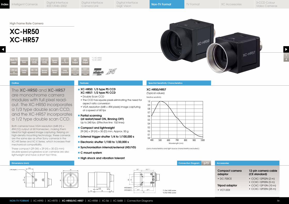
Connection Diagram p73Dimensions (mm)
1
4
XC-HR50XC-HR57
Outline
56
Accessories
Features
NON-TV FORMAT | XC-HR90 | XC-HR70 | XC-HR50/XC-HR57 | XC-HR58 | XC-56 | XC-56BB | Connection Diagrams
1/3 Type
CCD1/2 Type
CCDSquarePixelsOutput
Non-TV
RestartReset
LongExposure
HD / VDExternal Sync
NormalShutter
VSOutput
VGAOutput
ProgressiveScan
1/60 sec1N:
Non-interface
PartialScan
The XC-HR50 and XC-HR57 are monochrome camera modules with full pixel read-out. The XC-HR50 incorporates a 1/3 type double scan CCD, and the XC-HR57 incorporates a 1/2 type double scan CCD.
494 (V)) output at 60 frames/sec, making them ideal for high-speed image capturing. Relying on high-density mounting technology, these cameras
XC-HR Series and XC-E Series, which increases their mechanical compatibility.
double-speed progressive scan cameras are also lightweight and have a short tact time.
Spectral Sensitivity Characteristics
XC-HR50/HR57(Typical values)
Relative sensitivity
Wavelength (nm)
(Lens characteristics and light source characteristics excluded.)
XC-HR50: 1/3 type PS CCD XC-HR57: 1/2 type PS CCD
aspect ratio conversion
at a speed of 60 fps
Partial scanning (at restart/reset ON, Binning OFF)
Up to 240 fps. (Effective line: 102 lines)
Compact and lightweight
External trigger shutter 1/4 to 1/100,000 s
Electronic shutter 1/100 to 1/20,000 s
Synchronisation internal/external (HD/VD)
C mount system
High shock and vibration tolerant
Compact camera adaptor
Tripod adaptor
12-pin camera cable (CE standard)
CLens Mount
Mode 2(Non-Reset mode)
External Trigger Shutter
Mode 1(Non-Reset mode)
External Trigger Shutter
High Frame Rate Camera
*1: XC-HR50*2: XC-HR57
*1 *2
Non-TV FormatIndex Digital Interface IEEE1394b-2002
Digital Interface Camera Link
Digital InterfaceGigE Vision
TV Format XC Accessories3-CCD Colour Video Cameras
Intelligent Cameras
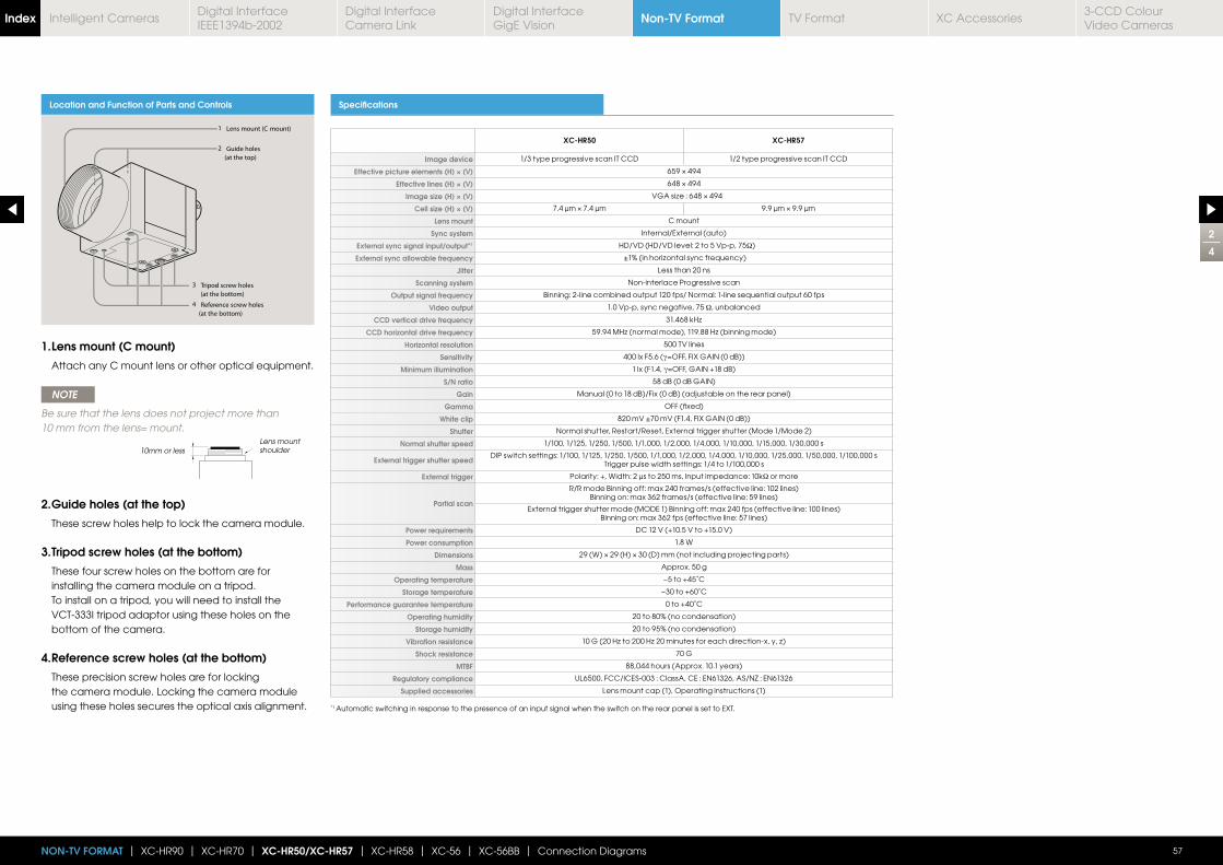
2
4
57NON-TV FORMAT | XC-HR90 | XC-HR70 | XC-HR50/XC-HR57 | XC-HR58 | XC-56 | XC-56BB | Connection Diagrams
Location and Function of Parts and Controls Specifications
XC-HR50 XC-HR57
Image device 1/3 type progressive scan IT CCD 1/2 type progressive scan IT CCD
Effective picture elements (H) × (V)
Effective lines (H) × (V)
Image size (H) × (V)
Cell size (H) × (V)
Lens mount C mount
Sync system Internal/External (auto)
External sync signal input/output*1 HD/VD (HD/VD level: 2 to 5 Vp-p, 75Ω)
External sync allowable frequency
Jitter Less than 20 ns
Scanning system Non-interlace Progressive scan
Output signal frequency Binning: 2-line combined output 120 fps/ Normal: 1-line sequential output 60 fps
Video output 1.0 Vp-p, sync negative, 75 Ω, unbalanced
CCD vertical drive frequency
CCD horizontal drive frequency
Horizontal resolution 500 TV lines
Sensitivity 400 lx F5.6 (γ
Minimum illumination 1 lx (F1.4, γ
S/N ratio 58 dB (0 dB GAIN)
Gain Manual (0 to 18 dB)/Fix (0 dB) (adjustable on the rear panel)
Gamma OFF (fixed)
White clip 820 mV ±70 mV (F1.4, FIX GAIN (0 dB))
Shutter Normal shutter, Restart/Reset, External trigger shutter (Mode 1/Mode 2)
Normal shutter speed 1/100, 1/125, 1/250, 1/500, 1/1,000, 1/2,000, 1/4,000, 1/10,000, 1/15,000, 1/30,000 s
External trigger shutter speedDIP switch settings: 1/100, 1/125, 1/250, 1/500, 1/1,000, 1/2,000, 1/4,000, 1/10,000, 1/25,000, 1/50,000, 1/100,000 s
Trigger pulse width settings: 1/4 to 1/100,000 s
External trigger Polarity: +, Width: 2 μs to 250 ms, Input impedance: 10kΩ or more
Partial scan
R/R mode Binning off: max 240 frames/s (effective line: 102 lines)Binning on: max 362 frames/s (effective line: 59 lines)
External trigger shutter mode (MODE 1) Binning off: max 240 fps (effective line: 100 lines)Binning on: max 362 fps (effective line: 57 lines)
Power requirements DC 12 V (+10.5 V to +15.0 V)
Power consumption 1.8 W
Dimensions
Mass Approx. 50 g
Operating temperature −5 to +45˚C
Storage temperature −30 to +60˚C
Performance guarantee temperature 0 to +40˚C
Operating humidity 20 to 80% (no condensation)
Storage humidity 20 to 95% (no condensation)
Vibration resistance
Shock resistance 70 G
MTBF 88,044 hours (Approx. 10.1 years)
Regulatory compliance UL6500, FCC/ICES-003 : ClassA, CE : EN61326, AS/NZ : EN61326
Supplied accessories Lens mount cap (1), Operating instructions (1)
1. Lens mount (C mount)
Attach any C mount lens or other optical equipment.
NOTE
Be sure that the lens does not project more than 10 mm from the lens= mount.
2. Guide holes (at the top)
These screw holes help to lock the camera module.
3. Tripod screw holes (at the bottom)
These four screw holes on the bottom are for installing the camera module on a tripod. To install on a tripod, you will need to install the VCT-333I tripod adaptor using these holes on the bottom of the camera.
4. Reference screw holes (at the bottom)
These precision screw holes are for locking the camera module. Locking the camera module using these holes secures the optical axis alignment.
10mm or lessLens mount shoulder
*1 Automatic switching in response to the presence of an input signal when the switch on the rear panel is set to EXT.
Non-TV FormatIndex Digital Interface IEEE1394b-2002
Digital Interface Camera Link
Digital InterfaceGigE Vision
TV Format XC Accessories3-CCD Colour Video Cameras
Intelligent Cameras
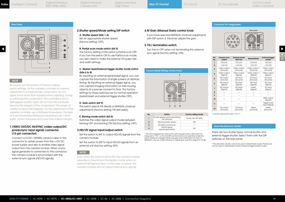
3
4
58NON-TV FORMAT | XC-HR90 | XC-HR70 | XC-HR50/XC-HR57 | XC-HR58 | XC-56 | XC-56BB | Connection Diagrams
Rear Panel
AA
BB
DDDEE
CC
NOTE
Be sure to turn the power off before making switch settings. As the variable controller for manual adjustment is a small precise component, do not apply force more than required when adjusting. Doing so will break the component. The controller is not a 360-degree rotation type. Do not turn the controller beyond the stopper of the component. The range of rotation is about 260 degrees. For the adjustment of the variable controller, use a flathead screwdriver. The sizes of a recommended flathead screwdrivers are 1.9mm width, 0.5mm thickness and more than 0.45mm length.
1. VIDEO OUT/DC IN/SYNC (video output/DC power/sync input signal) connector (12-pin connector)
Connect a CCXC-12P05N camera cable to this connector to obtain power from the +12V DC power supply and also to enable video signal output from the camera module. When a sync signal generator is connected to this connector, the camera module is synchronised with the external sync signals (HD/VD signals).
2. Shutter speed/Mode setting DIP switch
A. Shutter speed (bits 1-4) Set an appropriate shutter speed
(factory setting: OFF).
B. Partial scan mode switch (bit 5) The factory setting of this switch is Partial scan OFF.
If you turn this switch ON to use Partial scan mode, you also need to make the external VD pulse rate and width settings.
C. Restart reset/External trigger shutter mode switch (bits 6 to 8)
By inputting an external restart/reset signal, you can capture the information of single screens at arbitrary timing. By inputting an external trigger signal, you can capture imaging information on fast-moving objects at a precise moment in time. The factory settings for these switches are for normal operation (restart/reset and external trigger shutter OFF).
D. Gain switch (bit 9) This switch selects FIX (fixed) or MANUAL (manual
adjustment) (factory setting: FIX (left side)).
E. Binning mode switch (bit 0) Switches the video signal output mode between
binning OFF and binning ON (factory setting: OFF).
3. HD/VD signal input/output switch
Set the switch to INT to output HD/VD signals from the camera module.
Set the switch to EXT to input HD/VD signals from an external unit (factory setting: EXT).
NOTE:
Even when the switch is set to EXT, the camera module operates in internal synchronisation mode when no external HD signal is input. In this case, however, the camera module will not output internal sync signals.
4. M Gain (Manual Gain) control knob
If you have selected MANUAL (manual adjustment) with DIP switch 4, this knob adjusts the gain.
5. 75Ω termination switch
Turn this to OFF when not terminating the external sync signal (factory setting: ON).
Connector Pin Assignments
Pin No.
Camera sync output
External mode (HD/VD) Restart/Reset External trigger
shutter
1 Ground Ground Ground Ground
2 +12V DC +12V DC +12V DC +12V DC
3 Video output (Ground)
Video output (Ground)
Video output 1 (Ground)
Video output (Ground)
4 Video output (Signal)
Video output (Signal)
Video output 1 (Signal)
Video output (Signal)
5 HD output (Ground)
HD input (Ground)
HD input (Ground)
HD input (Ground)
6 HD output (Signal)
HD input(Signal)
HD input(Signal)
HD input(Signal)
7 VD output (Signal)
VD input(Signal)
Reset(Signal)
VD input(Signal)
8 — — — —
9 — — — —
10 — —WEN output
(Signal)
11 — — —Trigger pulse input (Signal)
12 VD output (Ground)
VD input (Ground)
Reset(Ground)
Reset(Ground)*
* Common ground for pins 7, 10, 11.
About the Electronic Shutter
There are two shutter types: normal shutter and external trigger shutter. Select them with the DIP switches on the rear panel.
* The electronic shutter cannot be used in restart/reset mode. Partial scan can be used in restart/reset mode in external trigger shutter mode1.
Factory Mode Settings of Rear Panel
No. Switch Factory setting mode
1 Shutter speed and mode setting DIP switches
All bits are OFF (left)
2 75Ω termination switch ON
3 M GAIN control knob — *
4 HD/VD signal input/output switch
EXT
* This unit is shipped from the factory with the gain switch (DIP switch 9) being set to “FIX,” so the M GAIN control knob is not operative unless the switch setting is changed. When the gain switch (DIP switch 9) is set to MANUAL, you can rotate this knob to adjust gain over the range 0 to 18 dB.
Non-TV FormatIndex Digital Interface IEEE1394b-2002
Digital Interface Camera Link
Digital InterfaceGigE Vision
TV Format XC Accessories3-CCD Colour Video Cameras
Intelligent Cameras
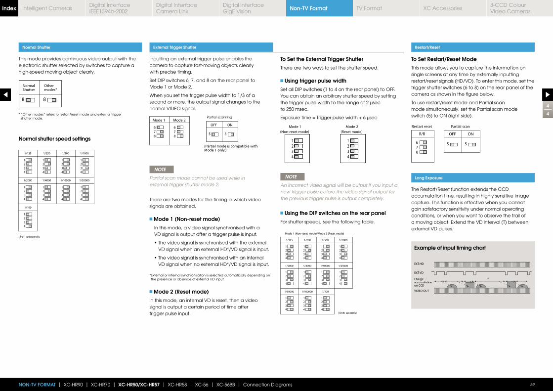
4
4
59NON-TV FORMAT | XC-HR90 | XC-HR70 | XC-HR50/XC-HR57 | XC-HR58 | XC-56 | XC-56BB | Connection Diagrams
Inputting an external trigger pulse enables the camera to capture fast-moving objects clearly with precise timing.
Set DIP switches 6, 7, and 8 on the rear panel to Mode 1 or Mode 2.
When you set the trigger pulse width to 1/3 of a second or more, the output signal changes to the normal VIDEO signal.
NOTE
Partial scan mode cannot be used while in external trigger shutter mode 2.
There are two modes for the timing in which video signals are obtained.
Mode 1 (Non-reset mode)
In this mode, a video signal synchronised with a VD signal is output after a trigger pulse is input.
VD signal when an external HD*/VD signal is input.
VD signal when no external HD*/VD signal is input.
* External or internal synchronisation is selected automatically depending on the presence or absence of external HD input.
Mode 2 (Reset mode)
In this mode, an internal VD is reset, then a video signal is output a certain period of time after trigger pulse input.
To Set the External Trigger Shutter
There are two ways to set the shutter speed.
Using trigger pulse width
Set all DIP switches (1 to 4 on the rear panel) to OFF.You can obtain an arbitrary shutter speed by setting the trigger pulse width to the range of 2 μsec to 250 msec.
NOTE
An incorrect video signal will be output if you input a new trigger pulse before the video signal output for the previous trigger pulse is output completely.
Using the DIP switches on the rear panel
For shutter speeds, see the following table.
This mode provides continuous video output with the electronic shutter selected by switches to capture a high-speed moving object clearly.
Normal Shutter External Trigger Shutter Restart/Reset
Long Exposure
To Set Restart/Reset Mode
This mode allows you to capture the information on single screens at any time by externally inputting restart/reset signals (HD/VD). To enter this mode, set the trigger shutter switches (6 to 8) on the rear panel of the camera as shown in the figure below.
To use restart/reset mode and Partial scan mode simultaneously, set the Partial scan mode switch (5) to ON (right side).
The Restart/Reset function extends the CCD accumulation time, resulting in highly sensitive image capture. This function is effective when you cannot gain satisfactory sensitivity under normal operating conditions, or when you want to observe the trail of a moving object. Extend the VD interval (T) between external VD pulses.
* “Other modes” refers to restart/reset mode and external trigger shutter mode.
Unit: seconds
Normal shutter speed settings
Example of input timing chart
Partial scanning
Non-TV FormatIndex Digital Interface IEEE1394b-2002
Digital Interface Camera Link
Digital InterfaceGigE Vision
TV Format XC Accessories3-CCD Colour Video Cameras
Intelligent Cameras
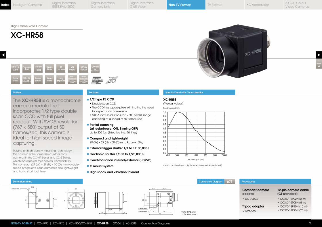
Dimensions (mm)
1
4
XC-HR58
The XC-HR58 is a monochrome camera module that incorporates 1/2 type double scan CCD with full pixel readout. With SVGA resolution
frames/sec, this camera is ideal for high-speed image capturing.
Relying on high-density mounting technology,
cameras in the XC-HR Series and XC-E Series, which increases its mechanical compatibility.
speed progressive scan camera is also lightweight and has a short tact time.
Outline
60
Accessories
Features
NON-TV FORMAT | XC-HR90 | XC-HR70 | XC-HR50/XC-HR57 | XC-HR58 | XC-56 | XC-56BB | Connection Diagrams
SquarePixels
1/2 Type
CCDOutputNon-TV
RestartReset
LongExposure
HD / VDExternal Sync
NormalShutter
VSOutput
SVGAOutput
ProgressiveScan
1/50 sec1N:
Non-interface
PartialScan
Features Spectral Sensitivity Characteristics
XC-HR58(Typical values)
Relative sensitivity
Wavelength (nm)
(Lens characteristics and light source characteristics excluded.)
1/2 type PS CCD
for aspect ratio conversion
capturing at a speed of 50 frames/sec
Partial scanning (at restart/reset ON, Binning OFF)
Up to 200 fps. (Effective line: 90 lines)
Compact and lightweight
External trigger shutter 1/4 to 1/100,000 s
Electronic shutter 1/100 to 1/20,000 s
Synchronisation internal/external (HD/VD)
C mount system
High shock and vibration tolerant
Compact camera adaptor
Tripod adaptor
12-pin camera cable (CE standard)
CLens Mount
Mode 2(Non-Reset mode)
External Trigger Shutter
Mode 1(Non-Reset mode)
External Trigger Shutter
High Frame Rate Camera
Connection Diagram p73
Non-TV FormatIndex Digital Interface IEEE1394b-2002
Digital Interface Camera Link
Digital InterfaceGigE Vision
TV Format XC Accessories3-CCD Colour Video Cameras
Intelligent Cameras
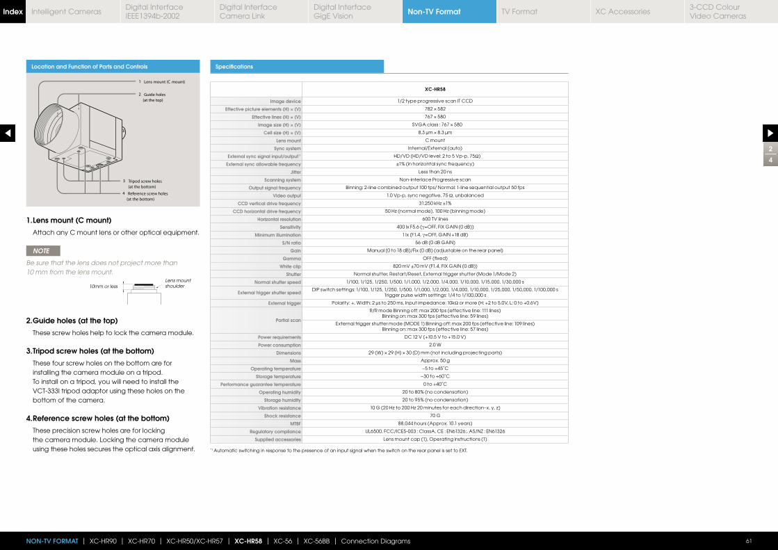
2
4
61NON-TV FORMAT | XC-HR90 | XC-HR70 | XC-HR50/XC-HR57 | XC-HR58 | XC-56 | XC-56BB | Connection Diagrams
Location and Function of Parts and Controls Specifications
XC-HR58
Image device 1/2 type progressive scan IT CCD
Effective picture elements (H) × (V)
Effective lines (H) × (V)
Image size (H) × (V)
Cell size (H) × (V)
Lens mount C mount
Sync system Internal/External (auto)
External sync signal input/output*1 HD/VD (HD/VD level: 2 to 5 Vp-p, 75Ω)
External sync allowable frequency
Jitter Less than 20 ns
Scanning system Non-interlace Progressive scan
Output signal frequency Binning: 2-line combined output 100 fps/ Normal: 1-line sequential output 50 fps
Video output 1.0 Vp-p, sync negative, 75 Ω, unbalanced
CCD vertical drive frequency
CCD horizontal drive frequency
Horizontal resolution 600 TV lines
Sensitivity 400 lx F5.6 (γ
Minimum illumination 1 lx (F1.4, γ
S/N ratio 56 dB (0 dB GAIN)
Gain Manual (0 to 18 dB)/Fix (0 dB) (adjustable on the rear panel)
Gamma OFF (fixed)
White clip 820 mV ±70 mV (F1.4, FIX GAIN (0 dB))
Shutter Normal shutter, Restart/Reset, External trigger shutter (Mode 1/Mode 2)
Normal shutter speed 1/100, 1/125, 1/250, 1/500, 1/1,000, 1/2,000, 1/4,000, 1/10,000, 1/15,000, 1/30,000 s
External trigger shutter speedDIP switch settings: 1/100, 1/125, 1/250, 1/500, 1/1,000, 1/2,000, 1/4,000, 1/10,000, 1/25,000, 1/50,000, 1/100,000 s
Trigger pulse width settings: 1/4 to 1/100,000 s
External trigger Polarity: +, Width: 2 μs to 250 ms, Input impedance: 10kΩ or more (H: +2 to 5.0V, L: 0 to +0.6V)
Partial scan
R/R mode Binning off: max 200 fps (effective line: 111 lines)Binning on: max 300 fps (effective line: 59 lines)
External trigger shutter mode (MODE 1) Binning off: max 200 fps (effective line: 109 lines)Binning on: max 300 fps (effective line: 57 lines)
Power requirements DC 12 V (+10.5 V to +15.0 V)
Power consumption 2.0 W
Dimensions
Mass Approx. 50 g
Operating temperature −5 to +45˚C
Storage temperature −30 to +60˚C
Performance guarantee temperature 0 to +40˚C
Operating humidity 20 to 80% (no condensation)
Storage humidity 20 to 95% (no condensation)
Vibration resistance
Shock resistance 70 G
MTBF 88,044 hours (Approx. 10.1 years)
Regulatory compliance UL6500, FCC/ICES-003 : ClassA, CE : EN61326:, AS/NZ : EN61326
Supplied accessories Lens mount cap (1), Operating instructions (1)
1. Lens mount (C mount)
Attach any C mount lens or other optical equipment.
NOTE
Be sure that the lens does not project more than 10 mm from the lens mount.
2. Guide holes (at the top)
These screw holes help to lock the camera module.
3. Tripod screw holes (at the bottom)
These four screw holes on the bottom are for installing the camera module on a tripod. To install on a tripod, you will need to install the VCT-333I tripod adaptor using these holes on the bottom of the camera.
4. Reference screw holes (at the bottom)
These precision screw holes are for locking the camera module. Locking the camera module using these holes secures the optical axis alignment.
10mm or lessLens mount shoulder
*1 Automatic switching in response to the presence of an input signal when the switch on the rear panel is set to EXT.
Non-TV FormatIndex Digital Interface IEEE1394b-2002
Digital Interface Camera Link
Digital InterfaceGigE Vision
TV Format XC Accessories3-CCD Colour Video Cameras
Intelligent Cameras
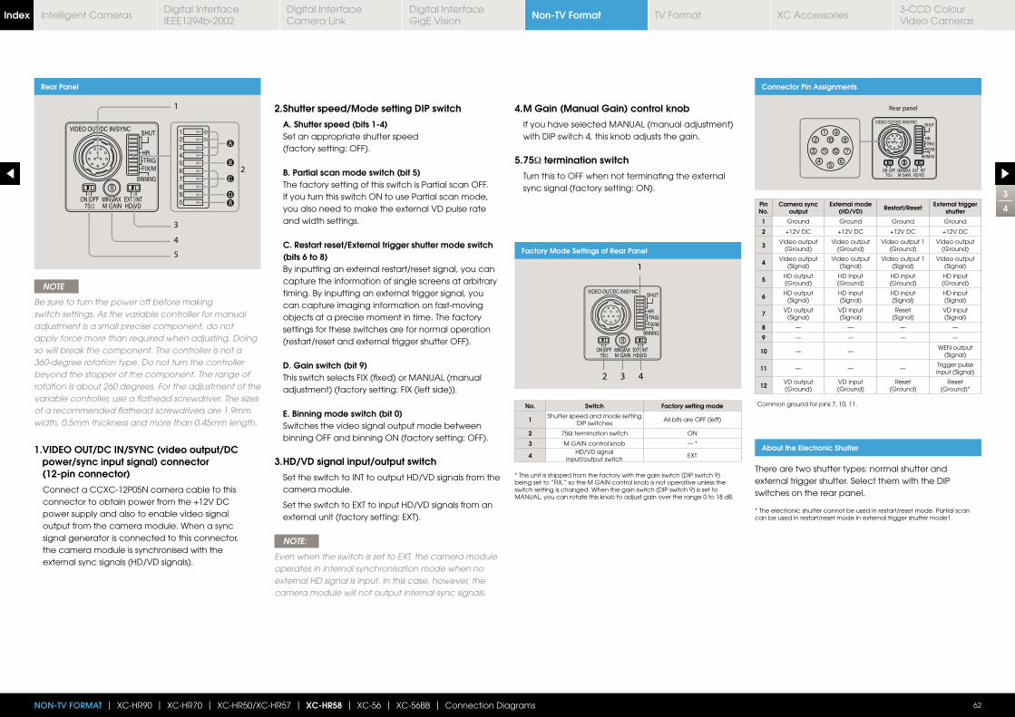
3
4
62NON-TV FORMAT | XC-HR90 | XC-HR70 | XC-HR50/XC-HR57 | XC-HR58 | XC-56 | XC-56BB | Connection Diagrams
Rear Panel
AA
BB
DDDEE
CC
NOTE
Be sure to turn the power off before making switch settings. As the variable controller for manual adjustment is a small precise component, do not apply force more than required when adjusting. Doing so will break the component. The controller is not a 360-degree rotation type. Do not turn the controller beyond the stopper of the component. The range of rotation is about 260 degrees. For the adjustment of the variable controller, use a flathead screwdriver. The sizes of a recommended flathead screwdrivers are 1.9mm width, 0.5mm thickness and more than 0.45mm length.
1. VIDEO OUT/DC IN/SYNC (video output/DC power/sync input signal) connector (12-pin connector)
Connect a CCXC-12P05N camera cable to this connector to obtain power from the +12V DC power supply and also to enable video signal output from the camera module. When a sync signal generator is connected to this connector, the camera module is synchronised with the external sync signals (HD/VD signals).
2. Shutter speed/Mode setting DIP switch
A. Shutter speed (bits 1-4) Set an appropriate shutter speed
(factory setting: OFF).
B. Partial scan mode switch (bit 5) The factory setting of this switch is Partial scan OFF.
If you turn this switch ON to use Partial scan mode, you also need to make the external VD pulse rate and width settings.
C. Restart reset/External trigger shutter mode switch (bits 6 to 8)
By inputting an external restart/reset signal, you can capture the information of single screens at arbitrary timing. By inputting an external trigger signal, you can capture imaging information on fast-moving objects at a precise moment in time. The factory settings for these switches are for normal operation (restart/reset and external trigger shutter OFF).
D. Gain switch (bit 9) This switch selects FIX (fixed) or MANUAL (manual
adjustment) (factory setting: FIX (left side)).
E. Binning mode switch (bit 0) Switches the video signal output mode between
binning OFF and binning ON (factory setting: OFF).
3. HD/VD signal input/output switch
Set the switch to INT to output HD/VD signals from the camera module.
Set the switch to EXT to input HD/VD signals from an external unit (factory setting: EXT).
NOTE:
Even when the switch is set to EXT, the camera module operates in internal synchronisation mode when no external HD signal is input. In this case, however, the camera module will not output internal sync signals.
4. M Gain (Manual Gain) control knob
If you have selected MANUAL (manual adjustment) with DIP switch 4, this knob adjusts the gain.
5. 75Ω termination switch
Turn this to OFF when not terminating the external sync signal (factory setting: ON).
Connector Pin Assignments
Pin No.
Camera sync output
External mode (HD/VD) Restart/Reset External trigger
shutter
1 Ground Ground Ground Ground
2 +12V DC +12V DC +12V DC +12V DC
3 Video output (Ground)
Video output (Ground)
Video output 1 (Ground)
Video output (Ground)
4 Video output (Signal)
Video output (Signal)
Video output 1 (Signal)
Video output (Signal)
5 HD output (Ground)
HD input (Ground)
HD input (Ground)
HD input (Ground)
6 HD output (Signal)
HD input(Signal)
HD input(Signal)
HD input(Signal)
7 VD output (Signal)
VD input(Signal)
Reset(Signal)
VD input(Signal)
8 — — — —
9 — — — —
10 — —WEN output
(Signal)
11 — — —Trigger pulse input (Signal)
12 VD output (Ground)
VD input (Ground)
Reset(Ground)
Reset(Ground)*
* Common ground for pins 7, 10, 11.
About the Electronic Shutter
There are two shutter types: normal shutter and external trigger shutter. Select them with the DIP switches on the rear panel.
* The electronic shutter cannot be used in restart/reset mode. Partial scan can be used in restart/reset mode in external trigger shutter mode1.
Factory Mode Settings of Rear Panel
No. Switch Factory setting mode
1 Shutter speed and mode setting DIP switches
All bits are OFF (left)
2 75Ω termination switch ON
3 M GAIN control knob — *
4 HD/VD signal input/output switch
EXT
* This unit is shipped from the factory with the gain switch (DIP switch 9) being set to “FIX,” so the M GAIN control knob is not operative unless the switch setting is changed. When the gain switch (DIP switch 9) is set to MANUAL, you can rotate this knob to adjust gain over the range 0 to 18 dB.
Non-TV FormatIndex Digital Interface IEEE1394b-2002
Digital Interface Camera Link
Digital InterfaceGigE Vision
TV Format XC Accessories3-CCD Colour Video Cameras
Intelligent Cameras

4
4
63NON-TV FORMAT | XC-HR90 | XC-HR70 | XC-HR50/XC-HR57 | XC-HR58 | XC-56 | XC-56BB | Connection Diagrams
Inputting an external trigger pulse enables the camera to capture fast-moving objects clearly with precise timing.
Set DIP switches 6, 7, and 8 on the rear panel to Mode 1 or Mode 2.
When you set the trigger pulse width to 1/3 of a second or more, the output signal changes to the normal VIDEO signal.
NOTE
Partial scan mode cannot be used while in external trigger shutter mode 2.
There are two modes for the timing in which video signals are obtained.
Mode 1 (Non-reset mode)
In this mode, a video signal synchronised with a VD signal is output after a trigger pulse is input.
VD signal when an external HD*/VD signal is input.
VD signal when no external HD*/VD signal is input.
* External or internal synchronisation is selected automatically depending on the presence or absence of external HD input.
Mode 2 (Reset mode)
In this mode, an internal VD is reset, then a video signal is output a certain period of time after trigger pulse input.
To Set the External Trigger Shutter
There are two ways to set the shutter speed.
Using trigger pulse width
Set all DIP switches (1 to 4 on the rear panel) to OFF.You can obtain an arbitrary shutter speed by setting the trigger pulse width to the range of 2 μsec to 250 msec.
NOTE
An incorrect video signal will be output if you input a new trigger pulse before the video signal output for the previous trigger pulse is output completely.
Using the DIP switches on the rear panel
For shutter speeds, see the following table.
This mode provides continuous video output with the electronic shutter selected by switches to capture a high-speed moving object clearly.
Normal Shutter External Trigger Shutter Restart/Reset
Long Exposure
To Set Restart/Reset Mode
This mode allows you to capture the information on single screens at any time by externally inputting restart/reset signals (HD/VD). To enter this mode, set the trigger shutter switches (6 to 8) on the rear panel of the camera as shown in the figure below.
To use restart/reset mode and Partial scan mode simultaneously, set the Partial scan mode switch (5) to ON (right side).
The Restart/Reset function extends the CCD accumulation time, resulting in highly sensitive image capture. This function is effective when you cannot gain satisfactory sensitivity under normal operating conditions, or when you want to observe the trail of a moving object. Extend the VD interval (T) between external VD pulses.
* “Other modes” refers to restart/reset mode and external trigger shutter mode.
Unit: seconds
Normal shutter speed settings
Example of input timing chart
Partial scanning
Non-TV FormatIndex Digital Interface IEEE1394b-2002
Digital Interface Camera Link
Digital InterfaceGigE Vision
TV Format XC Accessories3-CCD Colour Video Cameras
Intelligent Cameras

Connection Diagram p74Dimensions (mm)
Features Spectral Sensitivity Characteristics
1
4
XC-56
The XC-56 is a monochrome camera module that incorporates a 1/3 type progressive scan CCD. The XC-56 has VGA-class
output at 30 frames/sec. and 60 frames/sec. by the binning function.
which are the same as those of XC-HR Series. The pin assignment is compatible to the current XC-55.
Outline
64
Accessories
Features
NON-TV FORMAT | XC-HR90 | XC-HR70 | XC-HR50/XC-HR57 | XC-HR58 | XC-56 | XC-56BB | Connection Diagrams
SquarePixels
1/3 Type
CCDOutputNon-TV
RestartReset
LongExposure
HD / VDExternal Sync
NormalShutter
VSOutput
ProgressiveScan
1/30 sec1N:
Non-interface
PartialScan
VGAOutput*
XC-HR56(Typical values)
Relative sensitivity
Wavelength (nm)
(Lens characteristics and light source characteristics excluded.)
1/3 type progressive scan CCD
Non-TV format
Square pixel/ Full pixel read-out
VGA-class resolution image output, 30 frames/sec
Partial scanning function
External trigger shutter
Various settings are available on the rear panel
Compact camera adaptor
Tripod adaptor
12-pin camera cable (CE standard)
*When the image input board is connected
CLens Mount
Mode 2(Non-Reset mode)
External Trigger Shutter
Mode 1(Non-Reset mode)
External Trigger Shutter
Progressive Scan Camera Module
Non-TV FormatIndex Digital Interface IEEE1394b-2002
Digital Interface Camera Link
Digital InterfaceGigE Vision
TV Format XC Accessories3-CCD Colour Video Cameras
Intelligent Cameras
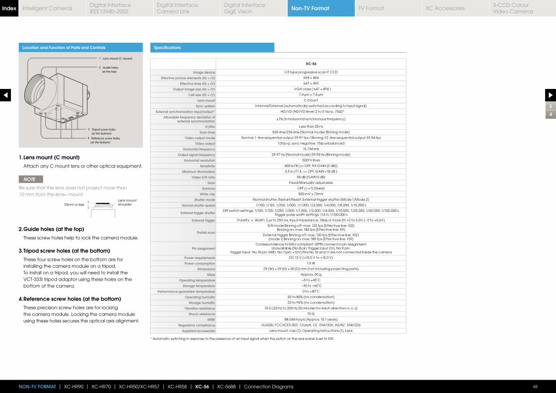
2
4
65NON-TV FORMAT | XC-HR90 | XC-HR70 | XC-HR50/XC-HR57 | XC-HR58 | XC-56 | XC-56BB | Connection Diagrams
Location and Function of Parts and Controls Specifications
XC-56
Image device 1/3 type progressive scan IT CCD
Effective picture elements (H) × (V)
Effective lines (H) × (V)
Output image size (H) × (V)
Cell size (H) × (V)
Lens mount C mount
Sync system Internal/External (automatically switched according to input signal)
External synchronization input/output*1 HD/VD (HD/VD level: 2 to 5 Vp-p, 75Ω)*
Allowable frequency deviation of external synchronization
H jitter Less than 20 ns
Scan lines 525-line/236-line (Normal mode/ Binning mode)
Video output mode Normal: 1 -line sequential output 29.97 fps / Binning: F2 -line sequential output 59.94 fps
Video output 1.0Vp-p, sync negative, 75Ω unbalanced
Horizontal frequency
Output signal frequency
Horizontal resolution 500TV lines
Sensitivity 400 lx F8 (γ
Minimum illumination 0.5 lx ( F1.4, γ
Video S/N ratio 58 dB (GAIN 0 dB)
Gain Fixed/Manually adjustable
Gamma OFF (γ
White clip 820 mV ± 70mV
Shutter mode Normal shutter, Restart/Reset, External trigger shutter (Mode 1/Mode 2)
Normal shutter speed 1/100, 1/125, 1/250, 1/500, 1/1,000, 1/2,000, 1/4,000, 1/8,000, 1/15,000 s
External trigger shutterDIP switch settings: 1/100, 1/125, 1/250, 1/500, 1/1,000, 1/2,000, 1/4,000, 1/10,000, 1/25,000, 1/50,000, 1/100,000 s
Trigger pulse width settings: 1/4 to 1/100,000 s
External trigger Polarity: +, Width: 2 μs to 250 ms, Input impedance: 10kΩ or more (H: +2 to 5.0V, L: 0 to +0.6V)
Partial scan
R/R mode Binning off: max: 120 fps (Effective line: 102)Binning on: max: 180 fps (Effective line: 59)
External trigger Binning off: max: 120 fps (Effective line: 102)(mode 1) Binning on: max: 180 fps (Effective line: 159)
Pin assignmentCorrespondence to EIAJ compliant 12PIN connector pin assignment
Unavailable (No.8 pin: Trigger input (G), No.9 pin:Trigger input, No.10 pin: GRD, No.11pin: +12V) Pins No.10 and 11 are not connected inside the camera
Power requirements DC 12 V (+10.5 V to +15.0 V)
Power consumption 1.5 W
Dimensions
Mass Approx. 50 g
Operating temperature −5 to +45˚C
Storage temperature −30 to +60˚C
Performance guarantee temperature 0 to +40˚C
Operating humidity 20 to 80% (no condensation)
Storage humidity 20 to 95% (no condensation)
Vibration resistance
Shock resistance 70 G
MTBF 88,044 hours (Approx. 10.1 years)
Regulatory compliance UL6500, FCC/ICES-003 : ClassA, CE : EN61326, AS/NZ : EN61326
Supplied accessories Lens mount cap (1), Operating instructions (1), Lens
1. Lens mount (C mount)
Attach any C mount lens or other optical equipment.
NOTE
Be sure that the lens does not project more than 10 mm from the lens= mount.
2. Guide holes (at the top)
These screw holes help to lock the camera module.
3. Tripod screw holes (at the bottom)
These four screw holes on the bottom are for installing the camera module on a tripod. To install on a tripod, you will need to install the VCT-333I tripod adaptor using these holes on the bottom of the camera.
4. Reference screw holes (at the bottom)
These precision screw holes are for locking the camera module. Locking the camera module using these holes secures the optical axis alignment.
10mm or lessLens mount shoulder
*1 Automatic switching in response to the presence of an input signal when the switch on the rear panel is set to EXT.
Non-TV FormatIndex Digital Interface IEEE1394b-2002
Digital Interface Camera Link
Digital InterfaceGigE Vision
TV Format XC Accessories3-CCD Colour Video Cameras
Intelligent Cameras
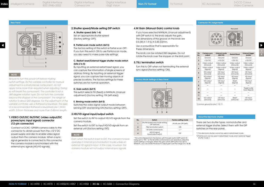
3
4
66NON-TV FORMAT | XC-HR90 | XC-HR70 | XC-HR50/XC-HR57 | XC-HR58 | XC-56 | XC-56BB | Connection Diagrams
Rear Panel
AA
BB
DDDEE
CC
NOTE
Be sure to turn the power off before making switch settings. As the variable controller for manual adjustment is a small precise component, do not apply force more than required when adjusting. Doing so will break the component. The controller is not a 360-degree rotation type. Do not turn the controller beyond the stopper of the component. The range of rotation is about 260 degrees. For the adjustment of the variable controller, use a flathead screwdriver. The sizes of a recommended flathead screwdrivers are 1.9mm width, 0.5mm thickness and more than 0.45mm length.
1. VIDEO OUT/DC IN/SYNC (video output/DC power/sync input signal) connector (12-pin connector)
Connect a CCXC-12P05N camera cable to this connector to obtain power from the +12 V DC power supply and also to enable video signal output from the camera module. When a sync signal generator is connected to this connector, the camera module is synchronised with the external sync signals (HD/VD signals).
2. Shutter speed/Mode setting DIP switch
A. Shutter speed (bits 1-4) Set an appropriate shutter speed
(factory setting: OFF).
B. Partial scan mode switch (bit 5) The factory setting of this switch is Partial scan OFF.
If you turn this switch ON to use Partial scan mode, you also need to make pulse rate settings.
C. Restart reset/External trigger shutter mode switch (bits 6 to 8)
By inputting an external restart/reset signal, you can capture the information of single screens at arbitrary timing. By inputting an external trigger signal, you can capture fast-moving objects at precise locations. The factory settings for these switches are for normal operation.
D. Gain switch (bit 9) This switch selects FIX (fixed) or MANUAL (manual
adjustment) (factory setting: FIX (left side)).
E. Binning mode switch (bit 0) Switches the video signal output mode between
binning OFF and binning ON (factory setting: OFF).
3. HD/VD signal input/output switch
Set the switch to INT to output HD/VD signals from the camera module.
Set the switch to EXT to input HD/VD signals from an external unit (factory setting: EXT).
NOTE:
Even when the switch is set to EXT, the camera module operates in internal synchronisation mode unless an external HD signal is input. In this case, however, the camera module will not output internal sync signals.
.
4. M Gain (Manual Gain) control knob
If you have selected MANUAL (manual adjustment) with DIP switch 4, this knob adjusts the gain. The dimensions of the groove on the knob are 0.5 (W) X 1.9 (L) X 0.45 (D)mm.
Use a screwdriver that is appropriate for these dimensions.
The knob can be rotated 260 degrees. Do not rotate the knob over the stopper on the limit point.
5. 75Ω termination switch
Turn this to OFF when not terminating the external sync signal (factory setting: ON).
Connector Pin Assignments
Pin No.
Camera sync output
External mode (HD/VD) Restart/Reset External trigger
shutter
1 Ground Ground Ground Ground
2 +12V DC +12V DC +12V DC +12V DC
3 Video output (Ground)
Video output (Ground)
Video output (Ground)
Video output (Ground)
4 Video output (Signal)
Video output (Signal)
Video output (Signal)
Video output (Signal)
5 HD output (Ground)
HD input (Ground)
HD input (Ground)
HD input (Ground)
6 HD output (Signal)
HD input(Signal)
HD input(Signal)
HD input(Signal)
7 VD output (Signal)
VD input(Signal)
Reset(Signal)
VD input(Signal)
8 — — — —
9 — — —Trigger pulse input (Signal)
10 — — — —
11 — — — —
12 VD output (Ground)
VD input (Ground)
Reset(Ground)
VD input (Ground)*
* Common ground for pins 7, 10, 11.
About the Electronic Shutter
There are two shutter types: normal shutter and external trigger shutter. Select them with the DIP switches on the rear panel.
*1 The electronic shutter cannot be used in restart/reset mode.
*2 Partial scan can be used in restart/reset mode and in external trigger shutter mode 1.
Factory Mode Settings of Rear Panel
No. Switch Factory setting mode
1 Shutter speed and mode setting DIP switches
All bits are OFF (left)
2 75Ω termination switch ON
3 M GAIN control knob — *
4 HD/VD signal input/output switch
EXT
* This unit is shipped from the factory with the gain switch (DIP switch 9) being set to “FIX,” so the M GAIN control knob is not operative unless the switch setting is changed. When the gain switch (DIP switch 9) is set to MANUAL, you can rotate this knob to adjust gain over the range 0 to 18 dB.
Non-TV FormatIndex Digital Interface IEEE1394b-2002
Digital Interface Camera Link
Digital InterfaceGigE Vision
TV Format XC Accessories3-CCD Colour Video Cameras
Intelligent Cameras
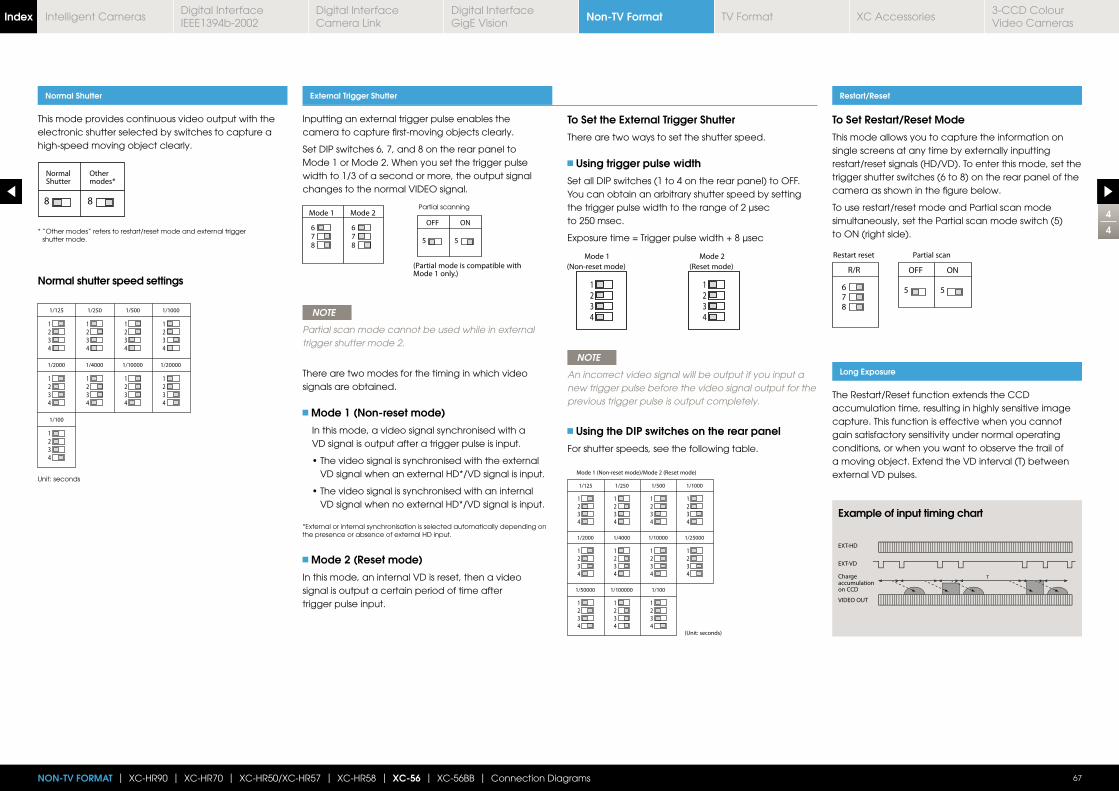
4
4
67NON-TV FORMAT | XC-HR90 | XC-HR70 | XC-HR50/XC-HR57 | XC-HR58 | XC-56 | XC-56BB | Connection Diagrams
Inputting an external trigger pulse enables the camera to capture first-moving objects clearly.
Set DIP switches 6, 7, and 8 on the rear panel to Mode 1 or Mode 2. When you set the trigger pulse width to 1/3 of a second or more, the output signal changes to the normal VIDEO signal.
NOTE
Partial scan mode cannot be used while in external trigger shutter mode 2.
There are two modes for the timing in which video signals are obtained.
Mode 1 (Non-reset mode)
In this mode, a video signal synchronised with a VD signal is output after a trigger pulse is input.
VD signal when an external HD*/VD signal is input.
VD signal when no external HD*/VD signal is input.
*External or internal synchronisation is selected automatically depending on the presence or absence of external HD input.
Mode 2 (Reset mode)
In this mode, an internal VD is reset, then a video signal is output a certain period of time after trigger pulse input.
To Set the External Trigger Shutter
There are two ways to set the shutter speed.
Using trigger pulse width
Set all DIP switches (1 to 4 on the rear panel) to OFF.You can obtain an arbitrary shutter speed by setting the trigger pulse width to the range of 2 μsec to 250 msec.
NOTE
An incorrect video signal will be output if you input a new trigger pulse before the video signal output for the previous trigger pulse is output completely.
Using the DIP switches on the rear panel
For shutter speeds, see the following table.
This mode provides continuous video output with the electronic shutter selected by switches to capture a high-speed moving object clearly.
Normal Shutter External Trigger Shutter Restart/Reset
Long Exposure
To Set Restart/Reset Mode
This mode allows you to capture the information on single screens at any time by externally inputting restart/reset signals (HD/VD). To enter this mode, set the trigger shutter switches (6 to 8) on the rear panel of the camera as shown in the figure below.
To use restart/reset mode and Partial scan mode simultaneously, set the Partial scan mode switch (5) to ON (right side).
The Restart/Reset function extends the CCD accumulation time, resulting in highly sensitive image capture. This function is effective when you cannot gain satisfactory sensitivity under normal operating conditions, or when you want to observe the trail of a moving object. Extend the VD interval (T) between external VD pulses.
* “Other modes” refers to restart/reset mode and external trigger shutter mode.
Unit: seconds
Normal shutter speed settings
Example of input timing chart
Partial scanning
Non-TV FormatIndex Digital Interface IEEE1394b-2002
Digital Interface Camera Link
Digital InterfaceGigE Vision
TV Format XC Accessories3-CCD Colour Video Cameras
Intelligent Cameras
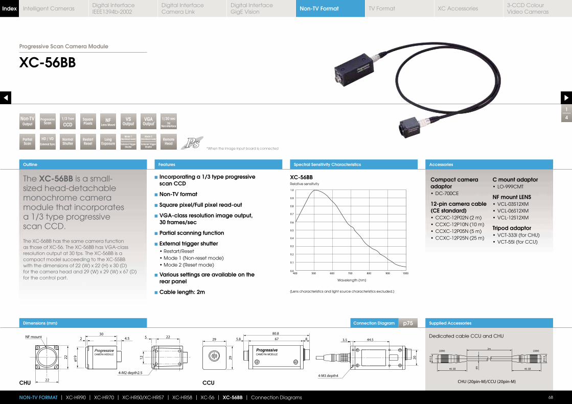
Connection Diagram p75 Supplied Accessories
Dedicated cable CCU and CHU
Compact camera adaptor
12-pin camera cable (CE standard)
C mount adaptor
NF mount LENS
Tripod adaptor
Dimensions (mm)
1
4
XC-56BB
The XC-56BB is a small-
monochrome camera module that incorporates a 1/3 type progressive scan CCD.
The XC-56BB has the same camera function as those of XC-56. The XC-56BB has VGA-class resolution output at 30 fps. The XC-56BB is a compact model succeeding to the XC-55BB with the dimensions of 22 (W) x 22 (H) x 30 (D) for the camera head and 29 (W) x 29 (W) x 67 (D) for the control part.
Outline
68
Features
NON-TV FORMAT | XC-HR90 | XC-HR70 | XC-HR50/XC-HR57 | XC-HR58 | XC-56 | XC-56BB | Connection Diagrams
SquarePixels
1/3 Type
CCDNF
Lens MountOutputNon-TV
RestartReset
LongExposure
HD / VDExternal Sync
NormalShutter
VSOutput
ProgressiveScan
1/30 sec1N:
Non-interface
PartialScan
Remote Head
VGAOutput*
Spectral Sensitivity Characteristics Accessories
XC-56BB
CHU CCU
Relative sensitivity
Wavelength (nm)
(Lens characteristics and light source characteristics excluded.)
Incorporating a 1/3 type progressive scan CCD
Non-TV format
Square pixel/Full pixel read-out
VGA-class resolution image output, 30 frames/sec
Partial scanning function
External trigger shutter
Various settings are available on the rear panel
Cable length: 2m
*When the image input board is connected
Mode 2(Non-Reset mode)
External Trigger Shutter
Mode 1(Non-Reset mode)
External Trigger Shutter
Progressive Scan Camera Module
Non-TV FormatIndex Digital Interface IEEE1394b-2002
Digital Interface Camera Link
Digital InterfaceGigE Vision
TV Format XC Accessories3-CCD Colour Video Cameras
Intelligent Cameras
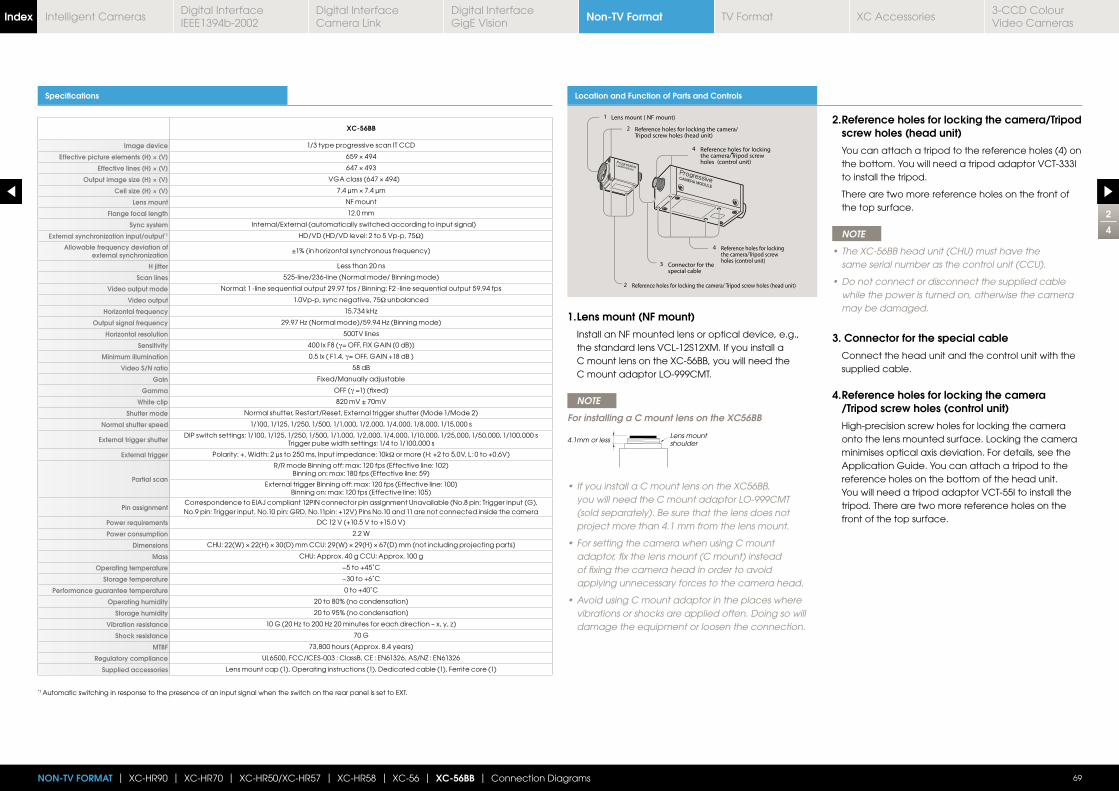
2
4
69NON-TV FORMAT | XC-HR90 | XC-HR70 | XC-HR50/XC-HR57 | XC-HR58 | XC-56 | XC-56BB | Connection Diagrams
Specifications
XC-56BB
Image device 1/3 type progressive scan IT CCD
Effective picture elements (H) × (V)
Effective lines (H) × (V)
Output image size (H) × (V)
Cell size (H) × (V)
Lens mount NF mount
Flange focal length 12.0 mm
Sync system Internal/External (automatically switched according to input signal)
External synchronization input/output*1 HD/VD (HD/VD level: 2 to 5 Vp-p, 75Ω)
Allowable frequency deviation of external synchronization
H jitter Less than 20 ns
Scan lines 525-line/236-line (Normal mode/ Binning mode)
Video output mode Normal: 1 -line sequential output 29.97 fps / Binning: F2 -line sequential output 59.94 fps
Video output 1.0Vp-p, sync negative, 75Ω unbalanced
Horizontal frequency
Output signal frequency
Horizontal resolution 500TV lines
Sensitivity 400 lx F8 (γ
Minimum illumination 0.5 lx ( F1.4, γ
Video S/N ratio 58 dB
Gain Fixed/Manually adjustable
Gamma OFF (γ
White clip 820 mV ± 70mV
Shutter mode Normal shutter, Restart/Reset, External trigger shutter (Mode 1/Mode 2)
Normal shutter speed 1/100, 1/125, 1/250, 1/500, 1/1,000, 1/2,000, 1/4,000, 1/8,000, 1/15,000 s
External trigger shutterDIP switch settings: 1/100, 1/125, 1/250, 1/500, 1/1,000, 1/2,000, 1/4,000, 1/10,000, 1/25,000, 1/50,000, 1/100,000 s
Trigger pulse width settings: 1/4 to 1/100,000 s
External trigger Polarity: +, Width: 2 μs to 250 ms, Input impedance: 10kΩ or more (H: +2 to 5.0V, L: 0 to +0.6V)
Partial scan
R/R mode Binning off: max: 120 fps (Effective line: 102)Binning on: max: 180 fps (Effective line: 59)
External trigger Binning off: max: 120 fps (Effective line: 100)Binning on: max: 120 fps (Effective line: 105)
Pin assignmentCorrespondence to EIAJ compliant 12PIN connector pin assignment Unavailable (No.8 pin: Trigger input (G), No.9 pin: Trigger input, No.10 pin: GRD, No.11pin: +12V) Pins No.10 and 11 are not connected inside the camera
Power requirements DC 12 V (+10.5 V to +15.0 V)
Power consumption 2.2 W
Dimensions
Mass CHU: Approx. 40 g CCU: Approx. 100 g
Operating temperature −5 to +45˚C
Storage temperature −30 to +6˚C
Performance guarantee temperature 0 to +40˚C
Operating humidity 20 to 80% (no condensation)
Storage humidity 20 to 95% (no condensation)
Vibration resistance
Shock resistance 70 G
MTBF 73,800 hours (Approx. 8.4 years)
Regulatory compliance UL6500, FCC/ICES-003 : ClassB, CE : EN61326, AS/NZ : EN61326
Supplied accessories Lens mount cap (1), Operating instructions (1), Dedicated cable (1), Ferrite core (1)
*1 Automatic switching in response to the presence of an input signal when the switch on the rear panel is set to EXT.
Location and Function of Parts and Controls
1. Lens mount (NF mount)
Install an NF mounted lens or optical device, e.g., the standard lens VCL-12S12XM. If you install a C mount lens on the XC-56BB, you will need the C mount adaptor LO-999CMT.
NOTE
For installing a C mount lens on the XC56BB
you will need the C mount adaptor LO-999CMT (sold separately). Be sure that the lens does not project more than 4.1 mm from the lens mount.
adaptor, fix the lens mount (C mount) instead of fixing the camera head in order to avoid applying unnecessary forces to the camera head.
vibrations or shocks are applied often. Doing so will damage the equipment or loosen the connection.
4.1mm or lessLens mountshoulder
2. Reference holes for locking the camera/Tripod screw holes (head unit)
You can attach a tripod to the reference holes (4) on the bottom. You will need a tripod adaptor VCT-333I to install the tripod.
There are two more reference holes on the front of the top surface.
NOTE
same serial number as the control unit (CCU).
while the power is turned on, otherwise the camera may be damaged.
3. Connector for the special cable
Connect the head unit and the control unit with the supplied cable.
4. Reference holes for locking the camera /Tripod screw holes (control unit)
High-precision screw holes for locking the camera onto the lens mounted surface. Locking the camera minimises optical axis deviation. For details, see the Application Guide. You can attach a tripod to the reference holes on the bottom of the head unit. You will need a tripod adaptor VCT-55I to install the tripod. There are two more reference holes on the front of the top surface.
Non-TV FormatIndex Digital Interface IEEE1394b-2002
Digital Interface Camera Link
Digital InterfaceGigE Vision
TV Format XC Accessories3-CCD Colour Video Cameras
Intelligent Cameras
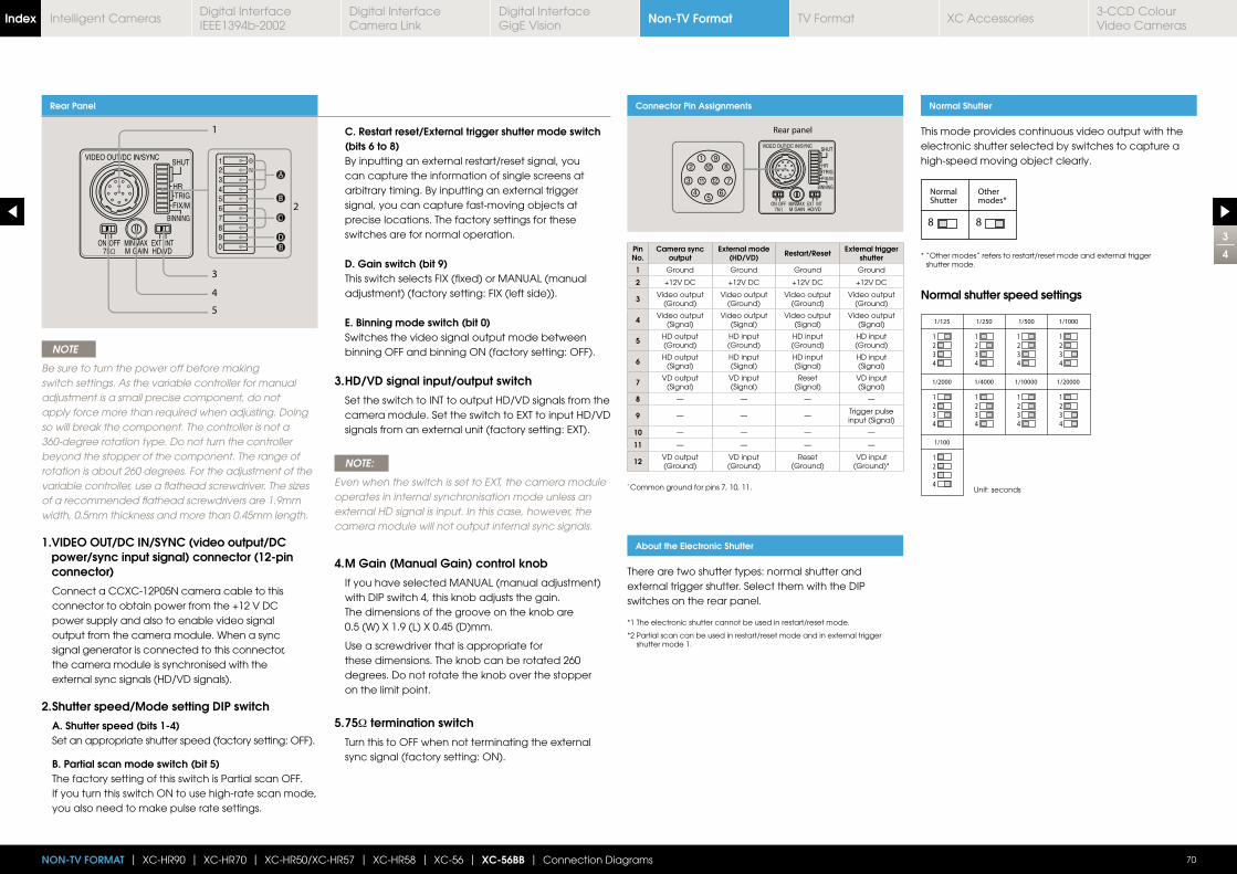
3
4
70NON-TV FORMAT | XC-HR90 | XC-HR70 | XC-HR50/XC-HR57 | XC-HR58 | XC-56 | XC-56BB | Connection Diagrams
Rear Panel
AA
BB
DDDEE
CC
NOTE
Be sure to turn the power off before making switch settings. As the variable controller for manual adjustment is a small precise component, do not apply force more than required when adjusting. Doing so will break the component. The controller is not a 360-degree rotation type. Do not turn the controller beyond the stopper of the component. The range of rotation is about 260 degrees. For the adjustment of the variable controller, use a flathead screwdriver. The sizes of a recommended flathead screwdrivers are 1.9mm width, 0.5mm thickness and more than 0.45mm length.
1. VIDEO OUT/DC IN/SYNC (video output/DC power/sync input signal) connector (12-pin connector)
Connect a CCXC-12P05N camera cable to this connector to obtain power from the +12 V DC power supply and also to enable video signal output from the camera module. When a sync signal generator is connected to this connector, the camera module is synchronised with the external sync signals (HD/VD signals).
2. Shutter speed/Mode setting DIP switch
A. Shutter speed (bits 1-4) Set an appropriate shutter speed (factory setting: OFF).
B. Partial scan mode switch (bit 5) The factory setting of this switch is Partial scan OFF.
If you turn this switch ON to use high-rate scan mode, you also need to make pulse rate settings.
C. Restart reset/External trigger shutter mode switch (bits 6 to 8)
By inputting an external restart/reset signal, you can capture the information of single screens at arbitrary timing. By inputting an external trigger signal, you can capture fast-moving objects at precise locations. The factory settings for these switches are for normal operation.
D. Gain switch (bit 9) This switch selects FIX (fixed) or MANUAL (manual
adjustment) (factory setting: FIX (left side)).
E. Binning mode switch (bit 0) Switches the video signal output mode between
binning OFF and binning ON (factory setting: OFF).
3. HD/VD signal input/output switch
Set the switch to INT to output HD/VD signals from the camera module. Set the switch to EXT to input HD/VD signals from an external unit (factory setting: EXT).
NOTE:
Even when the switch is set to EXT, the camera module operates in internal synchronisation mode unless an external HD signal is input. In this case, however, the camera module will not output internal sync signals.
4. M Gain (Manual Gain) control knob
If you have selected MANUAL (manual adjustment) with DIP switch 4, this knob adjusts the gain. The dimensions of the groove on the knob are 0.5 (W) X 1.9 (L) X 0.45 (D)mm.
Use a screwdriver that is appropriate for these dimensions. The knob can be rotated 260 degrees. Do not rotate the knob over the stopper on the limit point.
5. 75Ω termination switch
Turn this to OFF when not terminating the external sync signal (factory setting: ON).
Connector Pin Assignments
Pin No.
Camera sync output
External mode (HD/VD) Restart/Reset External trigger
shutter
1 Ground Ground Ground Ground
2 +12V DC +12V DC +12V DC +12V DC
3 Video output (Ground)
Video output (Ground)
Video output (Ground)
Video output (Ground)
4 Video output (Signal)
Video output (Signal)
Video output (Signal)
Video output (Signal)
5 HD output (Ground)
HD input (Ground)
HD input (Ground)
HD input (Ground)
6 HD output (Signal)
HD input(Signal)
HD input(Signal)
HD input(Signal)
7 VD output (Signal)
VD input(Signal)
Reset(Signal)
VD input(Signal)
8 — — — —
9 — — —Trigger pulse input (Signal)
10 — — — —
11 — — — —
12 VD output (Ground)
VD input (Ground)
Reset(Ground)
VD input (Ground)*
* Common ground for pins 7, 10, 11.
About the Electronic Shutter
There are two shutter types: normal shutter and external trigger shutter. Select them with the DIP switches on the rear panel.
*1 The electronic shutter cannot be used in restart/reset mode.
*2 Partial scan can be used in restart/reset mode and in external trigger shutter mode 1.
Unit: seconds
This mode provides continuous video output with the electronic shutter selected by switches to capture a high-speed moving object clearly.
Normal Shutter
* “Other modes” refers to restart/reset mode and external trigger shutter mode.
Normal shutter speed settings
Non-TV FormatIndex Digital Interface IEEE1394b-2002
Digital Interface Camera Link
Digital InterfaceGigE Vision
TV Format XC Accessories3-CCD Colour Video Cameras
Intelligent Cameras
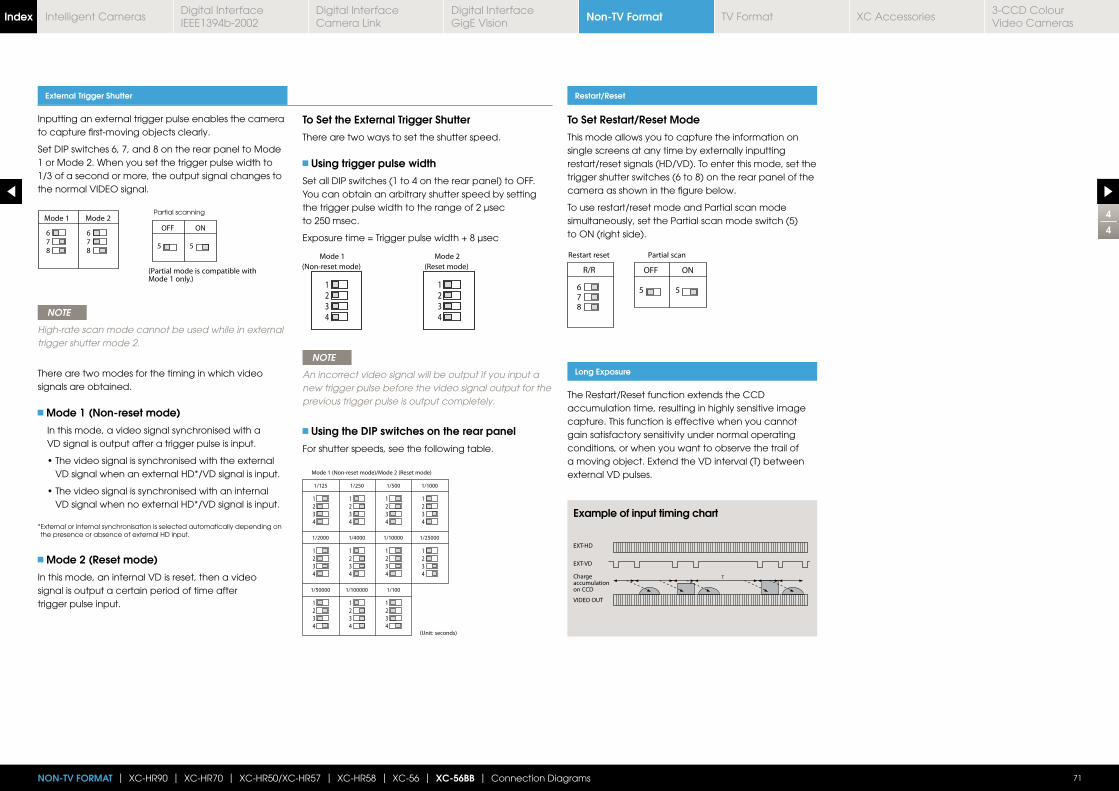
4
4
71NON-TV FORMAT | XC-HR90 | XC-HR70 | XC-HR50/XC-HR57 | XC-HR58 | XC-56 | XC-56BB | Connection Diagrams
Inputting an external trigger pulse enables the camera to capture first-moving objects clearly.
Set DIP switches 6, 7, and 8 on the rear panel to Mode 1 or Mode 2. When you set the trigger pulse width to 1/3 of a second or more, the output signal changes to the normal VIDEO signal.
NOTE
High-rate scan mode cannot be used while in external trigger shutter mode 2.
There are two modes for the timing in which video signals are obtained.
Mode 1 (Non-reset mode)
In this mode, a video signal synchronised with a VD signal is output after a trigger pulse is input.
VD signal when an external HD*/VD signal is input.
VD signal when no external HD*/VD signal is input.
* External or internal synchronisation is selected automatically depending on the presence or absence of external HD input.
Mode 2 (Reset mode)
In this mode, an internal VD is reset, then a video signal is output a certain period of time after trigger pulse input.
To Set the External Trigger Shutter
There are two ways to set the shutter speed.
Using trigger pulse width
Set all DIP switches (1 to 4 on the rear panel) to OFF.You can obtain an arbitrary shutter speed by setting the trigger pulse width to the range of 2 μsec to 250 msec.
NOTE
An incorrect video signal will be output if you input a new trigger pulse before the video signal output for the previous trigger pulse is output completely.
Using the DIP switches on the rear panel
For shutter speeds, see the following table.
External Trigger Shutter Restart/Reset
Long Exposure
To Set Restart/Reset Mode
This mode allows you to capture the information on single screens at any time by externally inputting restart/reset signals (HD/VD). To enter this mode, set the trigger shutter switches (6 to 8) on the rear panel of the camera as shown in the figure below.
To use restart/reset mode and Partial scan mode simultaneously, set the Partial scan mode switch (5) to ON (right side).
The Restart/Reset function extends the CCD accumulation time, resulting in highly sensitive image capture. This function is effective when you cannot gain satisfactory sensitivity under normal operating conditions, or when you want to observe the trail of a moving object. Extend the VD interval (T) between external VD pulses.
Example of input timing chart
Partial scanning
Non-TV FormatIndex Digital Interface IEEE1394b-2002
Digital Interface Camera Link
Digital InterfaceGigE Vision
TV Format XC Accessories3-CCD Colour Video Cameras
Intelligent Cameras
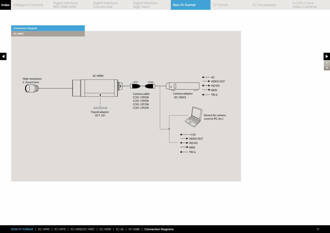
1
4
72NON-TV FORMAT | XC-HR90 | XC-HR70 | XC-HR50/XC-HR57 | XC-HR58 | XC-56 | XC-56BB | Connection Diagrams
Connection Diagram
XC-HR90
Non-TV FormatIndex Digital Interface IEEE1394b-2002
Digital Interface Camera Link
Digital InterfaceGigE Vision
TV Format XC Accessories3-CCD Colour Video Cameras
Intelligent Cameras
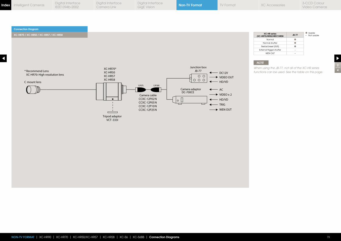
73NON-TV FORMAT | XC-HR90 | XC-HR70 | XC-HR50/XC-HR57 | XC-HR58 | XC-56 | XC-56BB | Connection Diagrams
2
4
Connection Diagram
XC-HR70 / XC-HR50 / XC-HR57 / XC-HR58
NOTE
When using the JB-77, not all of the XC-HR series functions can be used. See the table on this page.
XC-HR series(XC-HR70/HR50/HR57/HR58 JB-77
Normal
Normal shutter
Restart/reset (R/R)
External trigger shutter –
WEN OUT –
Usable– Not usable
Non-TV FormatIndex Digital Interface IEEE1394b-2002
Digital Interface Camera Link
Digital InterfaceGigE Vision
TV Format XC Accessories3-CCD Colour Video Cameras
Intelligent Cameras
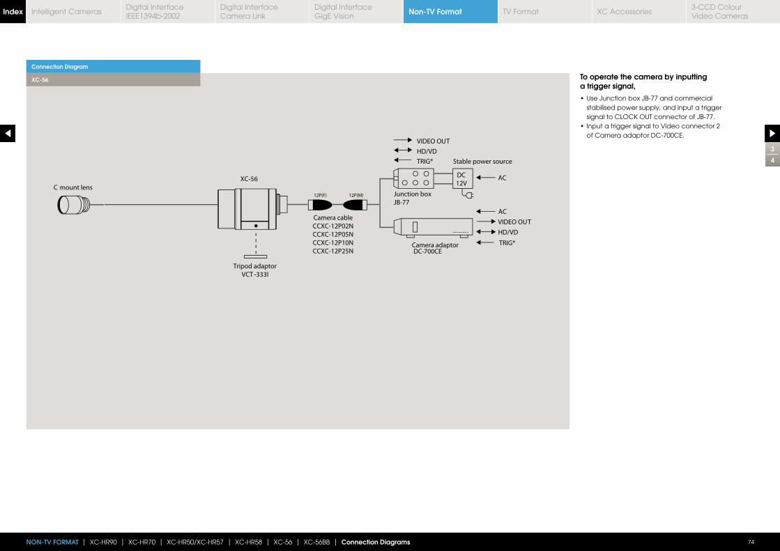
74NON-TV FORMAT | XC-HR90 | XC-HR70 | XC-HR50/XC-HR57 | XC-HR58 | XC-56 | XC-56BB | Connection Diagrams
3
4
Connection Diagram
XC-56 To operate the camera by inputting a trigger signal,
stabilised power supply, and input a trigger
of Camera adaptor DC-700CE.
Non-TV FormatIndex Digital Interface IEEE1394b-2002
Digital Interface Camera Link
Digital InterfaceGigE Vision
TV Format XC Accessories3-CCD Colour Video Cameras
Intelligent Cameras
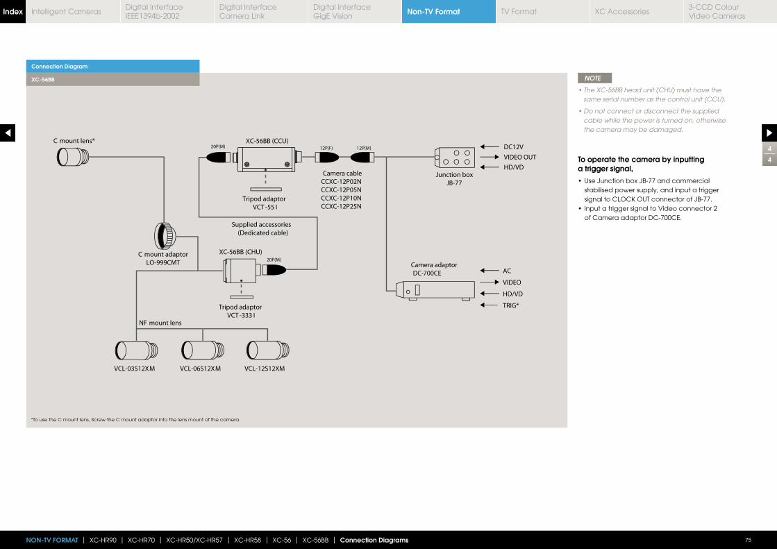
75NON-TV FORMAT | XC-HR90 | XC-HR70 | XC-HR50/XC-HR57 | XC-HR58 | XC-56 | XC-56BB | Connection Diagrams
4
4
Connection Diagram
XC-56BB NOTE
same serial number as the control unit (CCU).
cable while the power is turned on, otherwise the camera may be damaged.
To operate the camera by inputting a trigger signal,
stabilised power supply, and input a trigger
of Camera adaptor DC-700CE.
*To use the C mount lens, Screw the C mount adaptor into the lens mount of the camera.
Non-TV FormatIndex Digital Interface IEEE1394b-2002
Digital Interface Camera Link
Digital InterfaceGigE Vision
TV Format XC Accessories3-CCD Colour Video Cameras
Intelligent Cameras
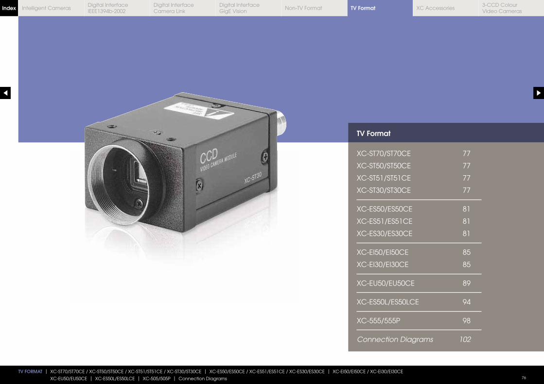
TV Format
XC-ST70/ST70CE 77
XC-ST50/ST50CE 77
XC-ST51/ST51CE 77
XC-ST30/ST30CE 77
XC-ES50/ES50CE 81
XC-ES51/ES51CE 81
XC-ES30/ES30CE 81
XC-EI50/EI50CE 85
XC-EI30/EI30CE 85
XC-EU50/EU50CE 89
XC-ES50L/ES50LCE 94
XC-555/555P 98
Connection Diagrams 102
TV FORMAT | XC-ST70/ST70CE / XC-ST50/ST50CE / XC-ST51/ST51CE / XC-ST30/ST30CE | XC-ES50/ES50CE / XC-ES51/ES51CE / XC-ES30/ES30CE | XC-EI50/EI50CE / XC-EI30/EI30CE
XC-EU50/EU50CE | XC-ES50L/ES50LCE | XC-505/505P | Connection Diagrams 76
TV FormatIndex Digital Interface IEEE1394b-2002
Digital Interface Camera Link
Digital InterfaceGigE Vision
Non-TV Format XC Accessories3-CCD Colour Video Cameras
Intelligent Cameras
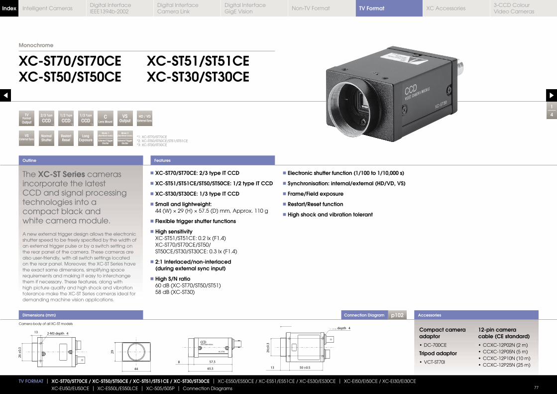
Connection Diagram p102Dimensions (mm)
1
4
XC-ST70/ST70CEXC-ST50/ST50CE
XC-ST51/ST51CEXC-ST30/ST30CE
The XC-ST Series cameras incorporate the latest CCD and signal processing technologies into a compact black and white camera module.
A new external trigger design allows the electronic shutter speed to be freely specified by the width of an external trigger pulse or by a switch setting on the rear panel of the camera. These cameras are also user-friendly, with all switch settings located on the rear panel. Moreover, the XC-ST Series have the exact same dimensions, simplifying space requirements and making it easy to interchange them if necessary. These features, along with high picture quality and high shock and vibration tolerance make the XC-ST Series cameras ideal for demanding machine vision applications.
XC-ST70/ST70CE: 2/3 type IT CCD
XC-ST51/ST51CE/ST50/ST50CE: 1/2 type IT CCD
XC-ST30/ST30CE: 1/3 type IT CCD
Small and lightweight:
Flexible trigger shutter functions
High sensitivity XC-ST51/ST51CE: 0.2 lx (F1.4) XC-ST70/ST70CE/ST50/ ST50CE/ST30/ST30CE: 0.3 lx (F1.4)
2:1 Interlaced/non-interlaced (during external sync input)
High S/N ratio 60 dB (XC-ST70/ST50/ST51) 58 dB (XC-ST30)
Electronic shutter function (1/100 to 1/10,000 s)
Synchronisation: internal/external (HD/VD, VS)
Frame/Field exposure
Restart/Reset function
High shock and vibration tolerant
Outline
Accessories
Features
Compact camera adaptor
Tripod adaptor
12-pin camera cable (CE standard)
*1: XC-ST70/ST70CE*2: XC-ST50/ST50CE/ST51/ST51CE*3: XC-ST30/ST30CE
Monochrome
TV FORMAT | XC-ST70/ST70CE / XC-ST50/ST50CE / XC-ST51/ST51CE / XC-ST30/ST30CE | XC-ES50/ES50CE / XC-ES51/ES51CE / XC-ES30/ES30CE | XC-EI50/EI50CE / XC-EI30/EI30CE
XC-EU50/EU50CE | XC-ES50L/ES50LCE | XC-505/505P | Connection Diagrams 77
2/3 Type
CCDC
Lens Mount
TVFormatOutput
Mode 2(Non-Reset mode)
External Trigger Shutter
RestartReset
LongExposure
HD / VDExternal Sync
VSExternal Sync
NormalShutter
Mode 1(Non-Reset mode)
External Trigger Shutter
VSOutput
1/2 Type
CCD*2
1/3 Type
CCD*3*1
Camera body of all XC-ST models
TV FormatIndex Digital Interface IEEE1394b-2002
Digital Interface Camera Link
Digital InterfaceGigE Vision
Non-TV Format XC Accessories3-CCD Colour Video Cameras
Intelligent Cameras
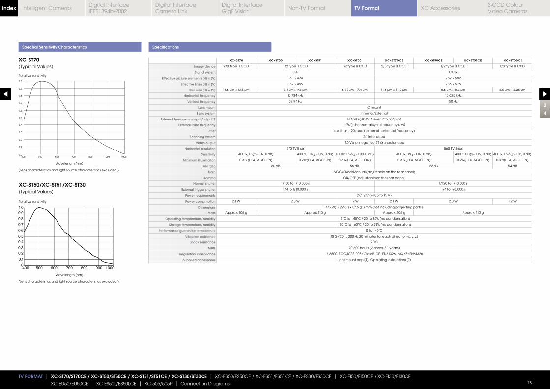
Spectral Sensitivity Characteristics Specifications
XC-ST70 XC-ST50 XC-ST51 XC-ST30 XC-ST70CE XC-ST50CE XC-ST51CE XC-ST30CE
Image device 2/3 type IT CCD 1/2 type IT CCD 1/3 type IT CCD 2/3 type IT CCD 1/2 type IT CCD 1/3 type IT CCD
Signal system EIA CCIR
Effective picture elements (H) × (V)
Effective lines (H) × (V)
Cell size (H) × (V)
Horizontal frequency
Vertical frequency
Lens mount C mount
Sync system Internal/External
External Sync system input/output*1 HD/VD (HD/VD level: 2 to 5 Vp-p)
External Sync frequency
Jitter
Scanning system 2:1 Interlaced
Video output 1.0 Vp-p, negative, 75 Ω unbalanced
Horizontal resolution 570 TV lines 560 TV lines
Sensitivity 400 lx, F8(γ 400 lx, F11(γ 400 lx, F5.6(γ 400 lx, F8(γ 400 lx, F11(γ 400 lx, F5.6(γ
Minimum illumination 0.3 lx (F1.4, AGC ON) 0.2 lx(F1.4, AGC ON) 0.3 lx(F1.4, AGC ON) 0.3 lx (F1.4, AGC ON) 0.2 lx(F1.4, AGC ON) 0.3 lx(F1.4, AGC ON)
S/N ratio 60 dB 56 dB 58 dB 54 dB
Gain AGC/Fixed/Manual (adjustable on the rear panel)
Gamma ON/OFF (adjustable on the rear panel)
Normal shutter 1/100 to 1/10,000 s 1/120 to 1/10,000 s
External trigger shutter 1/4 to 1/10,000 s 1/4 to 1/8,000 s
Power requirements DC12 V (+10.5 to 15 V)
Power consumption 2.1 W 2.0 W 1.9 W 2.1 W 2.0 W 1.9 W
Dimensions
Mass Approx. 105 g Approx. 110 g Approx. 105 g Approx. 110 g
Operating temperature/humidity −5˚C to +45˚C / 20 to 80% (no condensation)
Storage temperature/humidity −30˚C to +60˚C / 20 to 95% (no condensation)
Performance guarantee temperature 0 to +40˚C
Vibration resistance
Shock resistance 70 G
MTBF 70,600 hours (Approx. 8.1 years)
Regulatory compliance UL6500, FCC/ICES-003 : ClassB, CE : EN61326, AS/NZ : EN61326
Supplied accessories Lens mount cap (1), Operating instructions (1)
XC-ST70 (Typical Values)
XC-ST50/XC-ST51/XC-ST30(Typical Values)
Relative sensitivity
Wavelength (nm)
(Lens characteristics and light source characteristics excluded.)
Wavelength (nm)
(Lens characteristics and light source characteristics excluded.)
Relative sensitivity
2
4
TV FORMAT | XC-ST70/ST70CE / XC-ST50/ST50CE / XC-ST51/ST51CE / XC-ST30/ST30CE | XC-ES50/ES50CE / XC-ES51/ES51CE / XC-ES30/ES30CE | XC-EI50/EI50CE / XC-EI30/EI30CE
XC-EU50/EU50CE | XC-ES50L/ES50LCE | XC-505/505P | Connection Diagrams 78
TV FormatIndex Digital Interface IEEE1394b-2002
Digital Interface Camera Link
Digital InterfaceGigE Vision
Non-TV Format XC Accessories3-CCD Colour Video Cameras
Intelligent Cameras
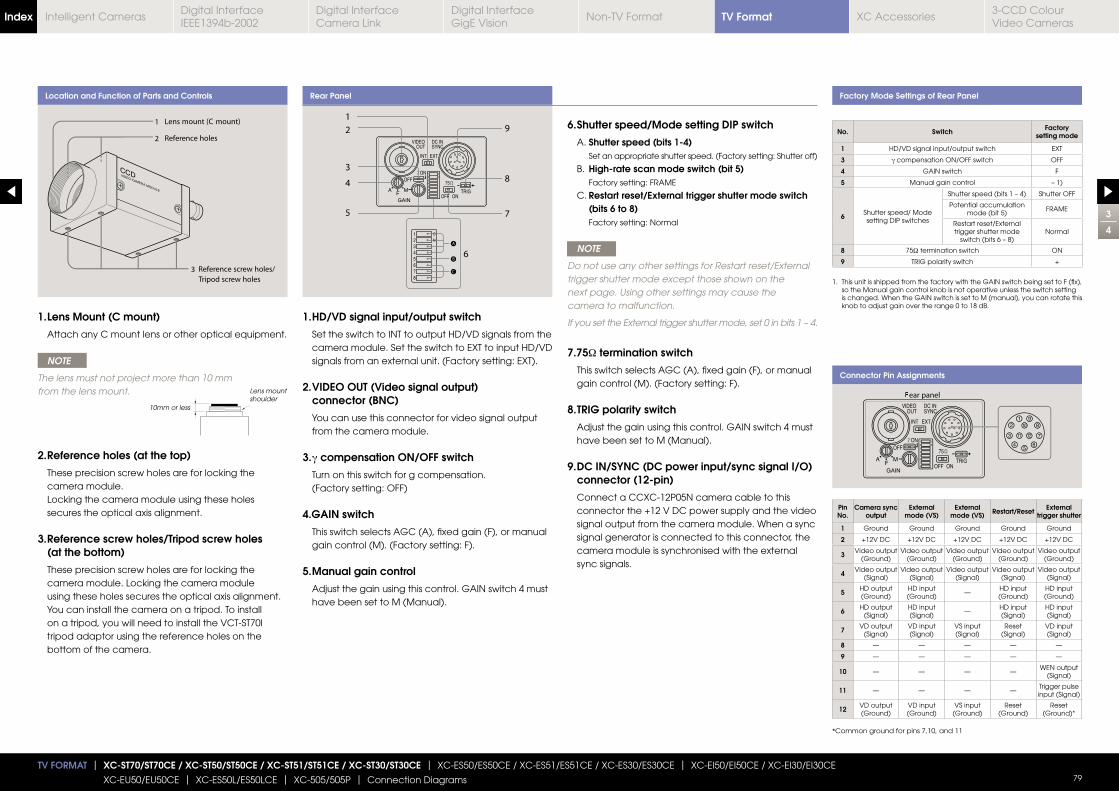
Location and Function of Parts and Controls Rear Panel Factory Mode Settings of Rear Panel
Connector Pin Assignments
A
B
C
1. HD/VD signal input/output switch
Set the switch to INT to output HD/VD signals from the camera module. Set the switch to EXT to input HD/VD signals from an external unit. (Factory setting: EXT).
2. VIDEO OUT (Video signal output) connector (BNC)
You can use this connector for video signal output from the camera module.
3. γ compensation ON/OFF switch
Turn on this switch for g compensation. (Factory setting: OFF)
4.GAIN switch
This switch selects AGC (A), fixed gain (F), or manual gain control (M). (Factory setting: F).
5. Manual gain control
Adjust the gain using this control. GAIN switch 4 must have been set to M (Manual).
1. Lens Mount (C mount)
Attach any C mount lens or other optical equipment.
NOTE
The lens must not project more than 10 mm from the lens mount.
2. Reference holes (at the top)
These precision screw holes are for locking the camera module. Locking the camera module using these holes secures the optical axis alignment.
3. Reference screw holes/Tripod screw holes (at the bottom)
These precision screw holes are for locking the camera module. Locking the camera module using these holes secures the optical axis alignment. You can install the camera on a tripod. To install on a tripod, you will need to install the VCT-ST70I tripod adaptor using the reference holes on the bottom of the camera.
6. Shutter speed/Mode setting DIP switch
A. Shutter speed (bits 1-4) Set an appropriate shutter speed. (Factory setting: Shutter off)
B. High-rate scan mode switch (bit 5) Factory setting: FRAME
C. Restart reset/External trigger shutter mode switch (bits 6 to 8) Factory setting: Normal
NOTE
Do not use any other settings for Restart reset/External trigger shutter mode except those shown on the next page. Using other settings may cause the camera to malfunction.
If you set the External trigger shutter mode, set 0 in bits 1 – 4.
7.75Ω termination switch
This switch selects AGC (A), fixed gain (F), or manual gain control (M). (Factory setting: F).
8. TRIG polarity switch
Adjust the gain using this control. GAIN switch 4 must have been set to M (Manual).
9. DC IN/SYNC (DC power input/sync signal I/O) connector (12-pin)
Connect a CCXC-12P05N camera cable to this connector the +12 V DC power supply and the video signal output from the camera module. When a sync signal generator is connected to this connector, the camera module is synchronised with the external sync signals.
1. This unit is shipped from the factory with the GAIN switch being set to F (fix), so the Manual gain control knob is not operative unless the switch setting is changed. When the GAIN switch is set to M (manual), you can rotate this knob to adjust gain over the range 0 to 18 dB.
*Common ground for pins 7,10, and 11
10mm or less
Lens mount shoulder
3
4
TV FORMAT | XC-ST70/ST70CE / XC-ST50/ST50CE / XC-ST51/ST51CE / XC-ST30/ST30CE | XC-ES50/ES50CE / XC-ES51/ES51CE / XC-ES30/ES30CE | XC-EI50/EI50CE / XC-EI30/EI30CE
XC-EU50/EU50CE | XC-ES50L/ES50LCE | XC-505/505P | Connection Diagrams 79
No. Switch Factory setting mode
1 HD/VD signal input/output switch EXT
3 γ compensation ON/OFF switch OFF
4 GAIN switch F
5 Manual gain control – 1)
6 Shutter speed/ Modesetting DIP switches
Shutter speed (bits 1 – 4) Shutter OFF
Potential accumulation mode (bit 5)
FRAME
Restart reset/External trigger shutter mode
switch (bits 6 – 8)Normal
8 75Ω termination switch ON
9 TRIG polarity switch +
Pin No.
Camera sync output
External mode (VS)
External mode (VS) Restart/Reset External
trigger shutter
1 Ground Ground Ground Ground Ground
2 +12V DC +12V DC +12V DC +12V DC +12V DC
3 Video output (Ground)
Video output (Ground)
Video output (Ground)
Video output (Ground)
Video output (Ground)
4 Video output (Signal)
Video output (Signal)
Video output (Signal)
Video output (Signal)
Video output (Signal)
5 HD output (Ground)
HD input (Ground)
—HD input (Ground)
HD input (Ground)
6 HD output (Signal)
HD input (Signal)
— HD input (Signal)
HD input (Signal)
7 VD output (Signal)
VD input (Signal)
VS input (Signal)
Reset(Signal)
VD input (Signal)
8 — — — — —
9 — — — — —
10 — — — —WEN output
(Signal)
11 — — — —Trigger pulse input (Signal)
12 VD output (Ground)
VD input (Ground)
VS input (Ground)
Reset (Ground)
Reset (Ground)*
TV FormatIndex Digital Interface IEEE1394b-2002
Digital Interface Camera Link
Digital InterfaceGigE Vision
Non-TV Format XC Accessories3-CCD Colour Video Cameras
Intelligent Cameras
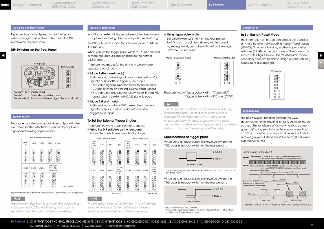
Inputting an external trigger pulse enables the camera to capture fast-moving objects clearly with precise timing.
Set DIP switches 6, 7, and 8 on the rear panel to Mode 1 or Mode 2.
When you set the trigger pulse width to 1/3 of a second or more, the output signal changes to the normal VIDEO signal.
There are two modes for the timing in which video signals are obtained.
Mode 1 (Non-reset mode) In this mode, a video signal synchronised with a VD signal is output after a trigger pulse is input.
VD signal when an external HD/VD signal is input.
signal when no external HD/VD signal is input.
Mode 2 (Reset mode) In this mode, an internal VD is reset, then a video signal is output a certain period of time after trigger pulse input.
To Set the External Trigger Shutter
There are two ways to set the shutter speed. Using the DIP switches on the rear panel For shutter speeds, see the following table.
There are two shutter types: normal shutter and external trigger shutter. Select them with the DIP switches on the rear panel.
DIP Switches on the Rear Panel
This mode provides continuous video output with the electronic shutter selected by switches to capture a high-speed moving object clearly.
NOTE
The DIP switch 5 position is optional. (The field setting is recommended.) The field setting can obtain a sensitivity that is twice that of the frame setting.
NOTE
The DIP switch 5 position is optional. (The field setting is recommended.) The field setting can obtain a sensitivity that is twice that of the frame setting.
About the Electronic Shutter
Normal Shutter
External Trigger Shutter
Long Exposure
Mode 2 (Reset mode)
(Unit: second)
1/100
(EIA)
1/120
(CCIR)
1/125
1/10000
(EIA)
1/8000
(CCIR)
1/250 1/500
1/1000 1/2000 1/4000
1/100
(EIA)
1/120
(CCIR)
1/125
1/10000
(EIA)
1/8000
(CCIR)
1/25 10 /500
1/1000 1/2000 1/4000
(Unit: second)
Mode 1 (Non-reset mode)
Restart/Reset
To Set Restart/Reset Mode
The information on one screen can be extracted at any time by externally inputting Restart/Reset signals (HD/VD). To enter this mode, set the trigger shutter switches (6 to 8) on the rear panel of the camera as shown in the figure below. The Reset/Restart mode is especially effective for frame image output with long exposure or a strobe light.
The Restart/Reset function extends the CCD accumulation time, resulting in highly sensitive image capture. This function is effective when you cannot gain satisfactory sensitivity under normal operating conditions, or when you want to observe the trail of a moving object. Extend the VD interval (T) between external VD pulses.
Using trigger pulse width Set all DIP switches (1 to 4 on the rear panel) to 0. You can obtain an arbitrary shutter speed by setting the trigger pulse width within the range of 2 msec to 250 msec.
Trigger pulse width + 120 μsec (CCIR)
NOTE
The DIP switch 5 position is optional. (The field setting is recommended.) The field setting can obtain a sensitivity that is twice that of the frame setting. If you input another trigger pulse before the video signal output for the previous trigger pulse is completely output, an incorrect video signal will be output.
Specifications of trigger pulse When using a trigger pulse like shown below, set the TRIG polarity selector switch on the rear panel to + :
When using a trigger pulse like shown below, set the TRIG polarity selector switch on the rear panel to - :
4
4
TV FORMAT | XC-ST70/ST70CE / XC-ST50/ST50CE / XC-ST51/ST51CE / XC-ST30/ST30CE | XC-ES50/ES50CE / XC-ES51/ES51CE / XC-ES30/ES30CE | XC-EI50/EI50CE / XC-EI30/EI30CE
XC-EU50/EU50CE | XC-ES50L/ES50LCE | XC-505/505P | Connection Diagrams 80
*If you set the mode to flickerless, the positions of DIP switches 1 to 3 are optional.
1. If you set the trigger pulse with the DIP switches, use the 100 μsec to 1/4 sec pulse width
Ω or more.
multi-connector on the rear panel.
μ
μ
TV FormatIndex Digital Interface IEEE1394b-2002
Digital Interface Camera Link
Digital InterfaceGigE Vision
Non-TV Format XC Accessories3-CCD Colour Video Cameras
Intelligent Cameras
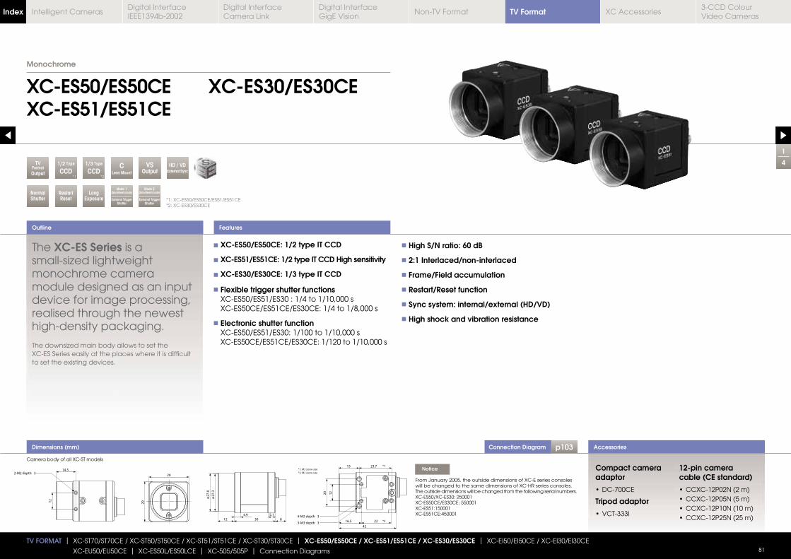
Connection Diagram p103
1
4
XC-ES50/ES50CEXC-ES51/ES51CE
XC-ES30/ES30CE
The XC-ES Series is a
monochrome camera module designed as an input device for image processing, realised through the newest high-density packaging.
XC-ES Series easily at the places where it is difficult to set the existing devices.
XC-ES50/ES50CE: 1/2 type IT CCD
XC-ES51/ES51CE: 1/2 type IT CCD High sensitivity
XC-ES30/ES30CE: 1/3 type IT CCD
Flexible trigger shutter functions XC-ES50/ES51/ES30 : 1/4 to 1/10,000 s
XC-ES50CE/ES51CE/ES30CE: 1/4 to 1/8,000 s
Electronic shutter function XC-ES50/ES51/ES30: 1/100 to 1/10,000 s
XC-ES50CE/ES51CE/ES30CE: 1/120 to 1/10,000 s
High S/N ratio: 60 dB
2:1 Interlaced/non-interlaced
Frame/Field accumulation
Restart/Reset function
Sync system: internal/external (HD/VD)
High shock and vibration resistance
Outline
Accessories
*1: XC-ES50/ES50CE/ES51/ES51CE*2: XC-ES30/ES30CE
Monochrome
TV FORMAT | XC-ST70/ST70CE / XC-ST50/ST50CE / XC-ST51/ST51CE / XC-ST30/ST30CE | XC-ES50/ES50CE / XC-ES51/ES51CE / XC-ES30/ES30CE | XC-EI50/EI50CE / XC-EI30/EI30CE
XC-EU50/EU50CE | XC-ES50L/ES50LCE | XC-505/505P | Connection Diagrams 81
RestartReset
LongExposure
NormalShutter
VSOutput
CLens Mount
TVFormatOutput
Mode 2(Non-Reset mode)
External Trigger Shutter
HD / VDExternal Sync
Mode 1(Non-Reset mode)
External Trigger Shutter
1/2 Type
CCD*1
1/3 Type
CCD*2
Features
Dimensions (mm)
Compact camera adaptor
Tripod adaptor
12-pin camera cable (CE standard)
Camera body of all XC-ST models
Notice
From January 2005, the outside dimensions of XC-E series consoles will be changed to the same dimensions of XC-HR series consoles.The outside dimensions will be changed from the following serial numbers.XC-ES50/XC-ES30: 250001XC-ES50CE/ES30CE: 550001XC-ES51:150001XC-ES51CE:450001
TV FormatIndex Digital Interface IEEE1394b-2002
Digital Interface Camera Link
Digital InterfaceGigE Vision
Non-TV Format XC Accessories3-CCD Colour Video Cameras
Intelligent Cameras
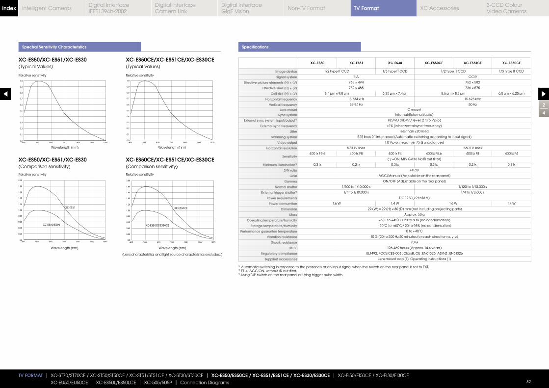
Spectral Sensitivity Characteristics Specifications
XC-ES50 XC-ES51 XC-ES30 XC-ES50CE XC-ES51CE XC-ES30CE
Image device 1/2 type IT CCD 1/3 type IT CCD 1/2 type IT CCD 1/3 type IT CCD
Signal system EIA CCIR
Effective picture elements (H) × (V)
Effective lines (H) × (V)
Cell size (H) × (V)
Horizontal frequency
Vertical frequencyLens mount C mount
Sync system Internal/External (auto)
External sync system input/output*1 HD/VD (HD/VD level: 2 to 5 Vp-p)
External sync frequency
Jitter less than ±20 nsec
Scanning system 525 lines 2:1 Interlaced (Automatic switching according to input signal)
Video output 1.0 Vp-p, negative, 75 Ω unbalanced
Horizontal resolution 570 TV lines 560 TV lines
Sensitivity 400 lx F5.6 400 lx F8 400 lx F4 400 lx F5.6 400 lx F8 400 lx F4
( γ
Minimum illumination*2 0.3 lx 0.2 lx 0.3 lx 0.3 lx 0.2 lx 0.3 lx
S/N ratio 60 dB
Gain AGC/Manual (Adjustable on the rear panel)
Gamma ON/OFF (Adjustable on the rear panel)
Normal shutter 1/100 to 1/10,000 s 1/120 to 1/10,000 s
External trigger shutter*3 1/4 to 1/10,000 s 1/4 to 1/8,000 s
Power requirements DC 12 V (+9 to16 V)
Power consumtion 1.6 W 1.4 W 1.6 W 1.4 W
Dimension
Mass Approx. 50 g
Operating temperature/humidity −5˚C to +45˚C / 20 to 80% (no condensation)
Storage temperature/humidity −20˚C to +60˚C / 20 to 95% (no condensation)
Performance guarantee temperature 0 to +40˚C
Vibration resistance
Shock resistance 70 G
MTBF 126,469 hours (Approx. 14.4 years)
Regulatory compliance UL1492, FCC/ICES-003 : ClassB, CE : EN61326, AS/NZ : EN61326
Supplied accessories Lens mount cap (1), Operating instructions (1)
XC-ES50/XC-ES51/XC-ES30(Typical Values)
XC-ES50/XC-ES51/XC-ES30(Comparison sensitivity)
XC-ES50CE/XC-ES51CE/XC-ES30CE(Typical Values)
XC-ES50CE/XC-ES51CE/XC-ES30CE(Comparison sensitivity)
Relative sensitivity Relative sensitivity
Wavelength (nm)
Wavelength (nm)
Wavelength (nm)
Wavelength (nm)
(Lens characteristics and light source characteristics excluded.)
Relative sensitivity Relative sensitivity
2
4
TV FORMAT | XC-ST70/ST70CE / XC-ST50/ST50CE / XC-ST51/ST51CE / XC-ST30/ST30CE | XC-ES50/ES50CE / XC-ES51/ES51CE / XC-ES30/ES30CE | XC-EI50/EI50CE / XC-EI30/EI30CE
XC-EU50/EU50CE | XC-ES50L/ES50LCE | XC-505/505P | Connection Diagrams 82
*1 Automatic switching in response to the presence of an input signal when the switch on the rear panel is set to EXT.*2 F1.4, AGC ON, without IR cut filter.*3 Using DIP switch on the rear panel or Using trigger pulse width.
TV FormatIndex Digital Interface IEEE1394b-2002
Digital Interface Camera Link
Digital InterfaceGigE Vision
Non-TV Format XC Accessories3-CCD Colour Video Cameras
Intelligent Cameras

3
4
TV FORMAT | XC-ST70/ST70CE / XC-ST50/ST50CE / XC-ST51/ST51CE / XC-ST30/ST30CE | XC-ES50/ES50CE / XC-ES51/ES51CE / XC-ES30/ES30CE | XC-EI50/EI50CE / XC-EI30/EI30CE
XC-EU50/EU50CE | XC-ES50L/ES50LCE | XC-505/505P | Connection Diagrams 83
Location and Function of Parts and Controls Rear Panel Factory Mode Settings of Rear Panel
Connector Pin Assignments1. 12-pin multi-connector
DC IN/HD/VD (DC power/sync signal input) VIDEO OUT terminal.
2. 75Ω termination selector switch
3. HD/VD input-output selector switch
4.Shutter speed/mode setting DIP switch
5. Volume control switch
This switch can be changed in the range of Switch 0 to 18 dB when the GAIN switch is set to “M”. * During factory setting, this switch is adjusted to the mechanical center.
1. Lens Mount (C mount)
Attach any C-mount lens or other optical equipment.
NOTE
Be sure that the lens does not project more than 10 mm from the lens mount.
2. Guide holes (at the top)
These screw holes help to lock the camera module.
3. Tripod screw holes (at the bottom)
These four screw holes on the bottom are for installing the camera module on a tripod. To install on a tripod, you will need to install the VCT-333I tripod adaptor using these holes on the bottom of the camera.
4. Reference screw holes (at the bottom)
These precision screw holes are for locking the camera module. Locking the camera module using these holes secures the optical axis alignment.
NOTE
When setting DIP switch 5 to the frame integration, set the volume control switch 8 to the MAX side from the mechanical center (because of CCD characteristics).
Be sure to turn the power off before making switch settings. As the variable controller for manual adjustment is a small precise component, do not apply force more than required when adjusting. Doing so will break the component. The controller is not a 360-degree rotation type. Do not turn the controller beyond the stopper of the component. The range of rotation is about 260 degrees. For the adjustment of the variable controller, use a flathead screwdriver. The sizes of a recommended flathead screwdrivers are 1.9mm width, 0.5mm thickness and more than 0.45mm length.
10mm or less
Lens mount shoulder
Pin No. External HD/VD synchronisation Internal HD/VD synchronisation
1 GND GND
2 +12 V +12 V
3 GND GND
4 VIDEO output VIDEO output
5 GND GND
6 External HD input Internal HD output
7 External VD input *1 Internal VD output
8 GND GND
9 — —
10 WEN output *2 WEN output *2
11 TRIG input TRIG input
12 GND GND
* The rear panel is different for the serial numbers shown below. XC-ES50/ES30 : 200001 XC-ES50CE/ES30CE : 500001
*1 An input VD signal is required when the restart/reset mode is used.*2 A WEN output signal is valid only in the external trigger shutter mode.
No. Switch Factory setting mode
2 75Ω termination selector switch ON
3 HD/VD signal input/output switch EXT
4 Shutter speed/ Modesetting DIP switches
Switches 1 to 4: Select the shutter speed.
OFF
Switch 5: Selects the frame or field integration.
FRAME
Switches 6 to 8: Select the trigger shutter mode
Normal
Switch 9: Selects correction on/off
OFF
Switch 0: Selects the gain Manual
5 Volume control switchMechanical
center
TV FormatIndex Digital Interface IEEE1394b-2002
Digital Interface Camera Link
Digital InterfaceGigE Vision
Non-TV Format XC Accessories3-CCD Colour Video Cameras
Intelligent Cameras
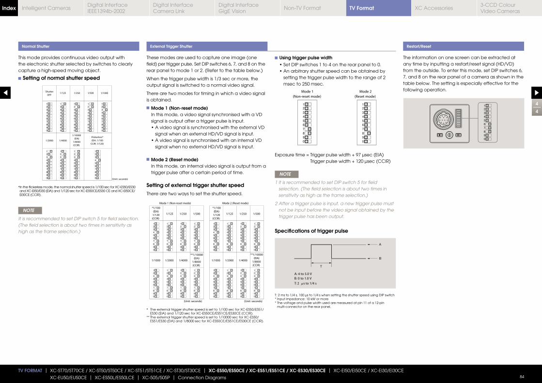
4
4
TV FORMAT | XC-ST70/ST70CE / XC-ST50/ST50CE / XC-ST51/ST51CE / XC-ST30/ST30CE | XC-ES50/ES50CE / XC-ES51/ES51CE / XC-ES30/ES30CE | XC-EI50/EI50CE / XC-EI30/EI30CE
XC-EU50/EU50CE | XC-ES50L/ES50LCE | XC-505/505P | Connection Diagrams 84
This mode provides continuous video output with the electronic shutter selected by switches to clearly capture a high-speed moving object.
Setting of normal shutter speed
NOTE
It is recommended to set DIP switch 5 for field selection. (The field selection is about two times in sensitivity as high as the frame selection.)
Normal Shutter External Trigger Shutter Restart/Reset
The information on one screen can be extracted at any time by inputting a restart/reset signal (HD/VD) from the outside. To enter this mode, set DIP switches 6, 7, and 8 on the rear panel of a camera as shown in the table below. The setting is especially effective for the following operation.
Using trigger pulse width
setting the trigger pulse width to the range of 2 msec to 250 msec.
Trigger pulse width + 120 μsec (CCIR)
NOTE
1 lt is recommended to set DIP switch 5 for field selection. (The field selection is about two times in sensitivity as high as the frame selection.)
2 After a trigger pulse is input, a new trigger pulse must not be input before the video signal obtained by the trigger pulse has been output.
Specifications of trigger pulse
T: 2 ms to 1/4 s, 100 μs to 1/4 s when setting the shutter speed using DIP switch* Input impedance: 10 kW or more* The voltage and pulse width used are measured at pin 11 of a 12-pin
multi-connector on the rear panel.
* In the flickerless mode, the normal shutter speed is 1/100 sec for XC-ES50/ES30 and XC-EI50/EI30 (EIA) and 1/120 sec for XC-ES50CE/ES30 CE and XC-EI50CE/EI30CE (CCIR).
These modes are used to capture one image (one field) per trigger pulse. Set DIP switches 6, 7, and 8 on the rear panel to mode 1 or 2. (Refer to the table below.)
When the trigger pulse width is 1/3 sec or more, the output signal is switched to a normal video signal.
There are two modes for timing in which a video signal is obtained.
Mode 1 (Non-reset mode) In this mode, a video signal synchronised with a VD signal is output after a trigger pulse is input.
signal when an external HD/VD signal is input.
signal when no external HD/VD signal is input.
Mode 2 (Reset mode) In this mode, an internal video signal is output from a trigger pulse after a certain period of time.
Setting of external trigger shutter speed
There are two ways to set the shutter speed.
* The external trigger shutter speed is set to 1/100 sec for XC-ES50/ES51/ES30 (EIA) and 1/120 sec for XC-ES50CE/ES51CE/ES30CE (CCIR).
** The external trigger shutter speed is set to 1/10000 sec for XC-ES50/ ES51/ES30 (EIA) and 1/8000 sec for XC-ES50CE/ES51CE/ES30CE (CCIR).
TV FormatIndex Digital Interface IEEE1394b-2002
Digital Interface Camera Link
Digital InterfaceGigE Vision
Non-TV Format XC Accessories3-CCD Colour Video Cameras
Intelligent Cameras
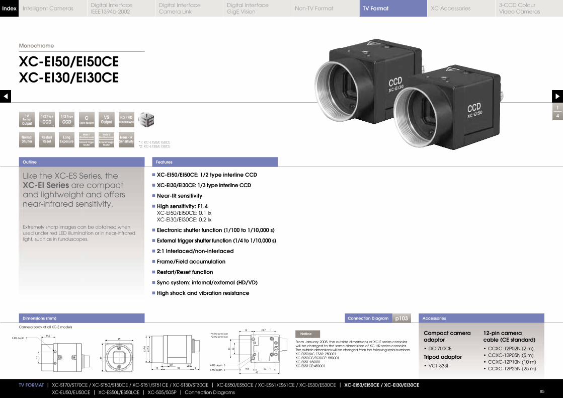
Connection Diagram p103
1/3 Type
CCD
1
4
XC-EI50/EI50CEXC-EI30/EI30CE
Outline
Accessories
*1: XC-E150/E150CE*2: XC-E130/E130CE
Monochrome
TV FORMAT | XC-ST70/ST70CE / XC-ST50/ST50CE / XC-ST51/ST51CE / XC-ST30/ST30CE | XC-ES50/ES50CE / XC-ES51/ES51CE / XC-ES30/ES30CE | XC-EI50/EI50CE / XC-EI30/EI30CE
XC-EU50/EU50CE | XC-ES50L/ES50LCE | XC-505/505P | Connection Diagrams 85
RestartReset
LongExposure
Near - IRSensitivity
NormalShutter
VSOutput
*2
CLens Mount
TVFormatOutput
Mode 2(Non-Reset mode)
External Trigger Shutter
HD / VDExternal Sync
Mode 1(Non-Reset mode)
External Trigger Shutter
1/2 Type
CCD*1
Features
Dimensions (mm)
Like the XC-ES Series, the XC-EI Series are compact and lightweight and offers near-infrared sensitivity.
Extremely sharp images can be obtained when used under red LED illumination or in near-infrared light, such as in funduscopes.
XC-EI50/EI50CE: 1/2 type interline CCD
XC-EI30/EI30CE: 1/3 type interline CCD
Near-IR sensitivity
High sensitivity: F1.4 XC-EI50/EI50CE: 0.1 lx XC-EI30/EI30CE: 0.2 lx
Electronic shutter function (1/100 to 1/10,000 s)
External trigger shutter function (1/4 to 1/10,000 s)
2:1 Interlaced/non-interlaced
Frame/Field accumulation
Restart/Reset function
Sync system: internal/external (HD/VD)
High shock and vibration resistance
Compact camera adaptor
Tripod adaptor
12-pin camera cable (CE standard)
Notice
From January 2005, the outside dimensions of XC-E series consoles will be changed to the same dimensions of XC-HR series consoles.The outside dimensions will be changed from the following serial numbers.XC-ES50/XC-ES30: 250001XC-ES50CE/ES30CE: 550001XC-ES51:150001XC-ES51CE:450001
Camera body of all XC-E models
TV FormatIndex Digital Interface IEEE1394b-2002
Digital Interface Camera Link
Digital InterfaceGigE Vision
Non-TV Format XC Accessories3-CCD Colour Video Cameras
Intelligent Cameras
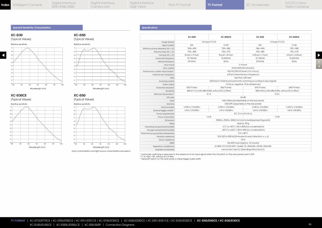
2
4
TV FORMAT | XC-ST70/ST70CE / XC-ST50/ST50CE / XC-ST51/ST51CE / XC-ST30/ST30CE | XC-ES50/ES50CE / XC-ES51/ES51CE / XC-ES30/ES30CE | XC-EI50/EI50CE / XC-EI30/EI30CE
XC-EU50/EU50CE | XC-ES50L/ES50LCE | XC-505/505P | Connection Diagrams 86
Spectral Sensitivity Characteristics Specifications
XC-EI50 XC-EI50CE XC-EI30 XC-EI30CE
Image device 1/2 type IT CCD 1/3 type IT CCD
Signal system EIA CCIR EIA CCIR
Effective picture elements (H) × (V)
Effective lines (H) × (V)
Cell size (H) × (V)
Horizontal frequency
Vertical frequency
Lens mount C mount
Sync system Internal/External (auto)
External sync system input/output*1 HD/VD (HD/VD level: 2 to 5 Vp-p)
External sync frequency
Jitter less than ±20 nsec
Scanning system 525 lines 2:1 Interlaced (automatic switching according to input signal)
Video output 1.0 Vp-p, negative, 75 Ω unbalanced
Horizontal resolution 570 TV lines 560 TV lines 570 TV lines 560 TV lines
Sensitivity 400 lx F11 (γ 400 lx F8 (γ
Minimum illumination*2 0.1 lx 0.2 lx
S/N ratio 60 dB
Gain AGC/Manual (adjustable on the rear panel)
Gamma ON/OFF (adjustable on the rear panel)
Normal shutter 1/100 to 1/10,000 s 1/120 to 1/10,000 s 1/100 to 1/10,000 s 1/120 to 1/10,000 s
External trigger shutter*3 1/4 to 1/10,000 s 1/4 to 1/8,000 s 1/4 to 1/10,000 s 1/4 to 1/8,000 s
Power requirements DC 12 V (+9 to16 V)
Power consumtion 1.6 W 1.4 W
Dimension
Mass Approx. 50 g
Operating temperature/humidity −5˚C to +45˚C / 20 to 80% (no condensation)
Storage temperature/humidity −20˚C to +60˚C / 20 to 95% (no condensation)
Performance guarantee temperature 0 to +40˚C
Vibration resistance
Shock resistance 70 G
MTBF 126,469 hours (Approx. 14.4 years)
Regulatory compliance UL1492, FCC/ICES-003 : ClassB, CE : EN61326, AS/NZ : EN61326
Supplied accessories Lens mount cap (1), Operating instructions (1)
XC-EI30(Typical Values)
XC-EI30CE(Typical Values)
XC-EI50(Typical Values)
XC-EI50(Typical Values)
Relative sensitivity Relative sensitivity
Wavelength (nm)
Wavelength (nm)
Wavelength (nm)
Wavelength (nm)
(Lens characteristics and light source characteristics excluded.)
Relative sensitivity Relative sensitivity
*1 Automatic switching in response to the presence of an input signal when the VS switch on the rear panel is set to EXT.*2 F1.4, AGC ON, without IR cut filter.*3 Using DIP switch on the rear panel or Using trigger pulse width.
TV FormatIndex Digital Interface IEEE1394b-2002
Digital Interface Camera Link
Digital InterfaceGigE Vision
Non-TV Format XC Accessories3-CCD Colour Video Cameras
Intelligent Cameras
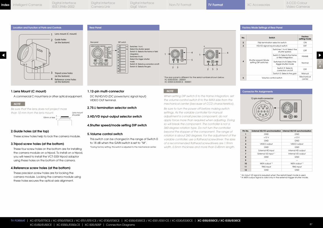
3
4
TV FORMAT | XC-ST70/ST70CE / XC-ST50/ST50CE / XC-ST51/ST51CE / XC-ST30/ST30CE | XC-ES50/ES50CE / XC-ES51/ES51CE / XC-ES30/ES30CE | XC-EI50/EI50CE / XC-EI30/EI30CE
XC-EU50/EU50CE | XC-ES50L/ES50LCE | XC-505/505P | Connection Diagrams 87
Location and Function of Parts and Controls Rear Panel Factory Mode Settings of Rear Panel
Connector Pin Assignments1. 12-pin multi-connector
DC IN/HD/VD (DC power/sync signal input) VIDEO OUT terminal.
2. 75 termination selector switch
3. HD/VD input-output selector switch
4.Shutter speed/mode setting DIP switch
5. Volume control switch
This switch can be changed in the range of Switch 0 to 18 dB when the GAIN switch is set to “M”. * During factory setting, this switch is adjusted to the mechanical center.
1. Lens Mount (C mount)
A commercial C mount lens or other optical equipment.
NOTE
Be sure that the lens does not project more than 10 mm from the lens mount.
2. Guide holes (at the top)
These screw holes help to lock the camera module.
3. Tripod screw holes (at the bottom)
These four screw holes on the bottom are for installing the camera module on a tripod. To install on a tripod, you will need to install the VCT-333I tripod adaptor using these holes on the bottom of the camera.
4. Reference screw holes (at the bottom)
These precision screw holes are for locking the camera module. Locking the camera module using these holes secures the optical axis alignment.
NOTE
When setting DIP switch 5 to the frame integration, set the volume control switch 8 to the MAX side from the mechanical center (because of CCD characteristics).
Be sure to turn the power off before making switch settings. As the variable controller for manual adjustment is a small precise component, do not apply force more than required when adjusting. Doing so will break the component. The controller is not a 360-degree rotation type. Do not turn the controller beyond the stopper of the component. The range of rotation is about 260 degrees. For the adjustment of the variable controller, use a flathead screwdriver. The sizes of a recommended flathead screwdrivers are 1.9mm width, 0.5mm thickness and more than 0.45mm length.
10mm or less
Lens mount shoulder
Pin No. External HD/VD synchronisation Internal HD/VD synchronisation
1 GND GND
2 +12 V +12 V
3 GND GND
4 VIDEO output VIDEO output
5 GND GND
6 External HD input Internal HD output
7 External VD input *1 Internal VD output
8 GND GND
9 — —
10 WEN output *2 WEN output *2
11 TRIG input TRIG input
12 GND GND
* The rear panel is different for the serial numbers shown below. XC-ES50/ES30 : 200001 XC-ES50CE/ES30CE : 500001
*1 An input VD signal is required when the restart/reset mode is used.*2 A WEN output signal is valid only in the external trigger shutter mode.
No. Switch Factory setting mode
2 75Ω termination selector switch ON
3 HD/VD signal input/output switch EXT
4 Shutter speed/ Modesetting DIP switches
Switches 1 to 4: Select the shutter speed.
OFF
Switch 5: Selects the frame or field integration.
FRAME
Switches 6 to 8: Select the trigger shutter mode
Normal
Switch 9: Selects correction on/off
OFF
Switch 0: Selects the gain Manual
5 Volume control switchMechanical
center
TV FormatIndex Digital Interface IEEE1394b-2002
Digital Interface Camera Link
Digital InterfaceGigE Vision
Non-TV Format XC Accessories3-CCD Colour Video Cameras
Intelligent Cameras
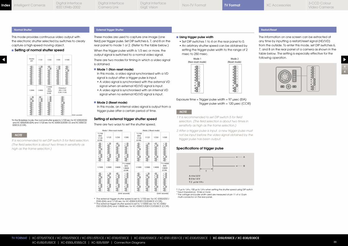
4
4
TV FORMAT | XC-ST70/ST70CE / XC-ST50/ST50CE / XC-ST51/ST51CE / XC-ST30/ST30CE | XC-ES50/ES50CE / XC-ES51/ES51CE / XC-ES30/ES30CE | XC-EI50/EI50CE / XC-EI30/EI30CE
XC-EU50/EU50CE | XC-ES50L/ES50LCE | XC-505/505P | Connection Diagrams 88
These modes are used to capture one image (one field) per trigger pulse. Set DIP switches 6, 7, and 8 on the rear panel to mode 1 or 2. (Refer to the table below.)
When the trigger pulse width is 1/3 sec or more, the output signal is switched to a normal video signal.
There are two modes for timing in which a video signal is obtained.
Mode 1 (Non-reset mode) In this mode, a video signal synchronised with a VD signal is output after a trigger pulse is input.
signal when an external HD/VD signal is input.
signal when no external HD/VD signal is input.
Mode 2 (Reset mode) In this mode, an internal video signal is output from a trigger pulse after a certain period of time.
Setting of external trigger shutter speed
There are two ways to set the shutter speed.
This mode provides continuous video output with the electronic shutter selected by switches to clearly capture a high-speed moving object.
Setting of normal shutter speed
NOTE
It is recommended to set DIP switch 5 for field selection. (The field selection is about two times in sensitivity as high as the frame selection.)
Normal Shutter External Trigger Shutter Restart/Reset
The information on one screen can be extracted at any time by inputting a restart/reset signal (HD/VD) from the outside. To enter this mode, set DIP switches 6, 7, and 8 on the rear panel of a camera as shown in the table below. The setting is especially effective for the following operation.
Using trigger pulse width
setting the trigger pulse width to the range of 2 msec to 250 msec.
Trigger pulse width + 120 μsec (CCIR)
NOTE
1 lt is recommended to set DIP switch 5 for field selection. (The field selection is about two times in sensitivity as high as the frame selection.)
2 After a trigger pulse is input, a new trigger pulse must not be input before the video signal obtained by the trigger pulse has been output.
Specifications of trigger pulse
T: 2 μs to 1/4 s, 100 μs to 1/4 s when setting the shutter speed using DIP switch* Input impedance: 10 kΩ or more* The voltage and pulse width used are measured at pin 11 of a 12-pin
multi-connector on the rear panel.
* In the flickerless mode, the normal shutter speed is 1/100 sec for XC-ES50/ES30 and XC-EI50/EI30 (EIA) and 1/120 sec for XC-ES50CE/ES30 CE and XC-EI50CE/EI30CE (CCIR).
* The external trigger shutter speed is set to 1/100 sec for XC-ES50/ES51/ES30 (EIA) and 1/120 sec for XC-ES50CE/ES51CE/ES30CE (CCIR).
** The external trigger shutter speed is set to 1/10000 sec for XC-ES50/ ES51/ES30 (EIA) and 1/8000 sec for XC-ES50CE/ES51CE/ES30CE (CCIR).
TV FormatIndex Digital Interface IEEE1394b-2002
Digital Interface Camera Link
Digital InterfaceGigE Vision
Non-TV Format XC Accessories3-CCD Colour Video Cameras
Intelligent Cameras
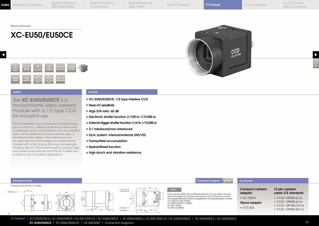
Connection Diagram p103
1
5
XC-EU50/EU50CE
Outline
Accessories
Monochrome
TV FORMAT | XC-ST70/ST70CE / XC-ST50/ST50CE / XC-ST51/ST51CE / XC-ST30/ST30CE | XC-ES50/ES50CE / XC-ES51/ES51CE / XC-ES30/ES30CE | XC-EI50/EI50CE / XC-EI30/EI30CE
XC-EU50/EU50CE | XC-ES50L/ES50LCE | XC-505/505P | Connection Diagrams 89
RestartReset
LongExposure
Near - IRSensitivity
NormalShutter
VSOutput
CLens Mount
TVFormatOutput
Mode 2(Non-Reset mode)
External Trigger Shutter
HD / VDExternal Sync
Mode 1(Non-Reset mode)
External Trigger Shutter
1/2 Type
CCD
Features
Dimensions (mm)
The XC-EU50/EU50CE is a monochrome video camera module with a 1/2 type CCD for industrial use.
With its sensitivity around the near ultraviolet range (around 365 nm), utilised the feature of the shorter wavelength range characteristics and very detailed data can be detected. Small scratches, dust or blemishes hardly visible to the naked eye can be captured as a clear image by combining the camera with a light source that has a wavelength
rear panel mode switches from the XC-E series and is ideal for use in industrial applications.
XC-EU50/EU50CE: 1/2 type interline CCD
Near-UV sensitivity
High S/N ratio: 60 dB
Electronic shutter function (1/100 to 1/10,000 s)
External trigger shutter function (1/4 to 1/10,000 s)
2:1 Interlaced/non-interlaced
Sync system: internal/external (HD/VD)
Frame/field accumulation
Restart/Reset function
High shock and vibration resistance
Compact camera adaptor
Tripod adaptor
12-pin camera cable (CE standard)
Notice
From January 2005, the outside dimensions of XC-E series consoles will be changed to the same dimensions of XC-HR series consoles.The outside dimensions will be changed from the following serial numbers.XC-ES50/XC-ES30: 250001XC-ES50CE/ES30CE: 550001XC-ES51:150001XC-ES51CE:450001
Camera body of all XC-E models
TV FormatIndex Digital Interface IEEE1394b-2002
Digital Interface Camera Link
Digital InterfaceGigE Vision
Non-TV Format XC Accessories3-CCD Colour Video Cameras
Intelligent Cameras
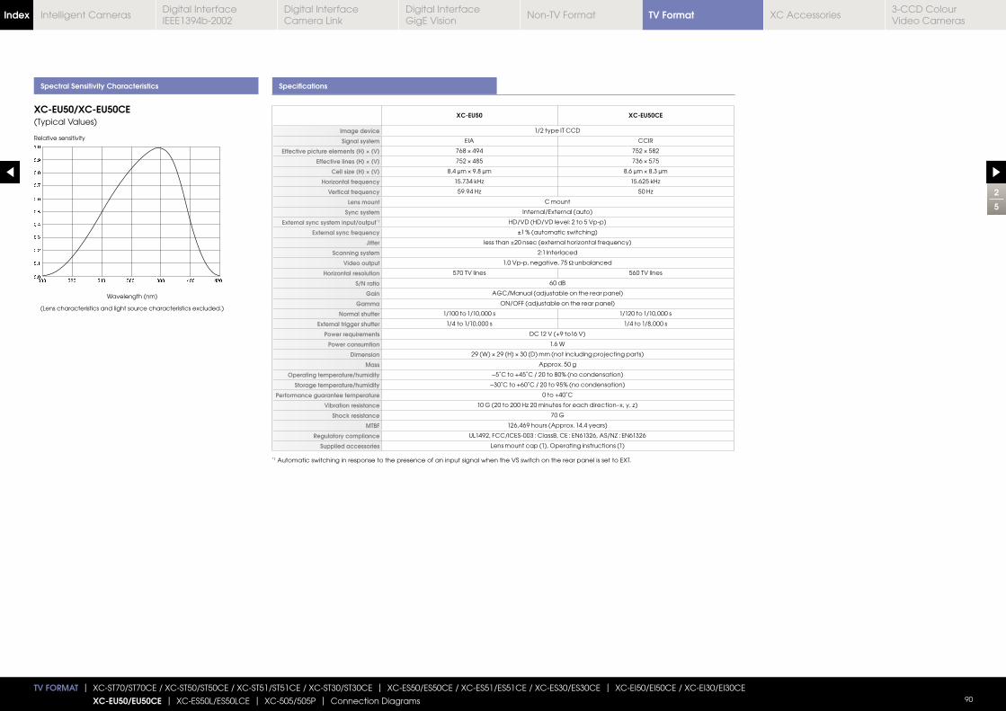
2
5
TV FORMAT | XC-ST70/ST70CE / XC-ST50/ST50CE / XC-ST51/ST51CE / XC-ST30/ST30CE | XC-ES50/ES50CE / XC-ES51/ES51CE / XC-ES30/ES30CE | XC-EI50/EI50CE / XC-EI30/EI30CE
XC-EU50/EU50CE | XC-ES50L/ES50LCE | XC-505/505P | Connection Diagrams 90
Spectral Sensitivity Characteristics Specifications
XC-EU50 XC-EU50CE
Image device 1/2 type IT CCD
Signal system EIA CCIR
Effective picture elements (H) × (V)
Effective lines (H) × (V)
Cell size (H) × (V)
Horizontal frequency
Vertical frequency
Lens mount C mount
Sync system Internal/External (auto)
External sync system input/output*1 HD/VD (HD/VD level: 2 to 5 Vp-p)
External sync frequency ±1 % (automatic switching)
Jitter
Scanning system 2:1 Interlaced
Video output 1.0 Vp-p, negative, 75 Ω unbalanced
Horizontal resolution 570 TV lines 560 TV lines
S/N ratio 60 dB
Gain AGC/Manual (adjustable on the rear panel)
Gamma ON/OFF (adjustable on the rear panel)
Normal shutter 1/100 to 1/10,000 s 1/120 to 1/10,000 s
External trigger shutter 1/4 to 1/10,000 s 1/4 to 1/8,000 s
Power requirements DC 12 V (+9 to16 V)
Power consumtion 1.6 W
Dimension
Mass Approx. 50 g
Operating temperature/humidity −5˚C to +45˚C / 20 to 80% (no condensation)
Storage temperature/humidity −30˚C to +60˚C / 20 to 95% (no condensation)
Performance guarantee temperature 0 to +40˚C
Vibration resistance
Shock resistance 70 G
MTBF 126,469 hours (Approx. 14.4 years)
Regulatory compliance UL1492, FCC/ICES-003 : ClassB, CE : EN61326, AS/NZ : EN61326
Supplied accessories Lens mount cap (1), Operating instructions (1)
XC-EU50/XC-EU50CE(Typical Values)
Relative sensitivity
Wavelength (nm)
(Lens characteristics and light source characteristics excluded.)
*1 Automatic switching in response to the presence of an input signal when the VS switch on the rear panel is set to EXT.
TV FormatIndex Digital Interface IEEE1394b-2002
Digital Interface Camera Link
Digital InterfaceGigE Vision
Non-TV Format XC Accessories3-CCD Colour Video Cameras
Intelligent Cameras
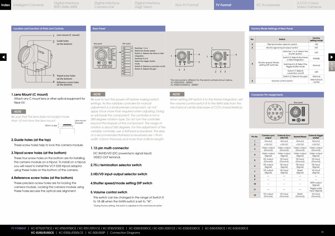
3
5
TV FORMAT | XC-ST70/ST70CE / XC-ST50/ST50CE / XC-ST51/ST51CE / XC-ST30/ST30CE | XC-ES50/ES50CE / XC-ES51/ES51CE / XC-ES30/ES30CE | XC-EI50/EI50CE / XC-EI30/EI30CE
XC-EU50/EU50CE | XC-ES50L/ES50LCE | XC-505/505P | Connection Diagrams 91
Location and Function of Parts and Controls Rear Panel Factory Mode Settings of Rear Panel
Connector Pin Assignments NOTE
Be sure to turn the power off before making switch settings. As the variable controller for manual adjustment is a small precise component, do not apply force more than required when adjusting. Doing so will break the component. The controller is not a 360-degree rotation type. Do not turn the controller beyond the stopper of the component. The range of rotation is about 260 degrees. For the adjustment of the variable controller, use a flathead screwdriver. The sizes of a recommended flathead screwdrivers are 1.9mm width, 0.5mm thickness and more than 0.45mm length.
1. 12-pin multi-connector
DC IN/HD/VD (DC power/sync signal input) VIDEO OUT terminal.
2.75 termination selector switch
3. HD/VD input-output selector switch
4.Shutter speed/mode setting DIP switch
5. Volume control switch
This switch can be changed in the range of Switch 0 to 18 dB when the GAIN switch is set to “M”. * During factory setting, this switch is adjusted to the mechanical center.
1. Lens Mount (C mount) Attach any C mount lens or other optical equipment for Near UV.
NOTE
Be sure that the lens does not project more than 10 mm from the lens mount.
2. Guide holes (at the top)
These screw holes help to lock the camera module.
3. Tripod screw holes (at the bottom)
These four screw holes on the bottom are for installing the camera module on a tripod. To install on a tripod, you will need to install the VCT-333I tripod adaptor using these holes on the bottom of the camera.
4. Reference screw holes (at the bottom)
These precision screw holes are for locking the camera module. Locking the camera module using these holes secures the optical axis alignment.
NOTE
When setting DIP switch 5 to the frame integration, set the volume control switch 8 to the MAX side from the mechanical center (because of CCD characteristics).
10mm or less
Lens mount shoulder
Pin No. Camera sync output
External Sync (HD/VD) Restart/Reset External trigger
shutter
1 Ground Ground Ground Ground
2 +12V DC +12V DC +12V DC +12V DC
3 Video output (Ground)
Video output (Ground)
Video output (Ground)
Video output (Ground)
4 Video output (Signal)
Video output (Signal)
Video output (Signal)
Video output (Signal)
5 HD output (Ground)
HD input (Ground)
HD input (Ground)
HD input (Ground)
6 HD output (Signal)
HD input (Signal)
HD input (Signal)
HD input (Signal)
7 VD output (Signal)
VD input (Signal)
Reset(Signal)
VD input (Signal)
8 — — — —
9 — — — —
10 — — —WEN output
(Signal)
11 — — —Trigger pulse input (Signal)
12 VD output (Ground)
VD input (Ground)
Reset(Ground)
VD input (Ground)
* The rear panel is different for the serial numbers shown below. XC-ES50/ES30 : 200001 XC-ES50CE/ES30CE : 500001
No. Switch Factory setting mode
2 75Ω termination selector switch ON
3 HD/VD signal input/output switch EXT
4 Shutter speed/ Modesetting DIP switches
Switches 1 to 4: Select the shutter speed.
OFF
Switch 5: Selects the frame or field integration.
FRAME
Switches 6 to 8: Select the trigger shutter mode
Normal
Switch 9: Selects correction on/off
OFF
Switch 0: Selects the gain Manual
5 Volume control switchMechanical
center
TV FormatIndex Digital Interface IEEE1394b-2002
Digital Interface Camera Link
Digital InterfaceGigE Vision
Non-TV Format XC Accessories3-CCD Colour Video Cameras
Intelligent Cameras
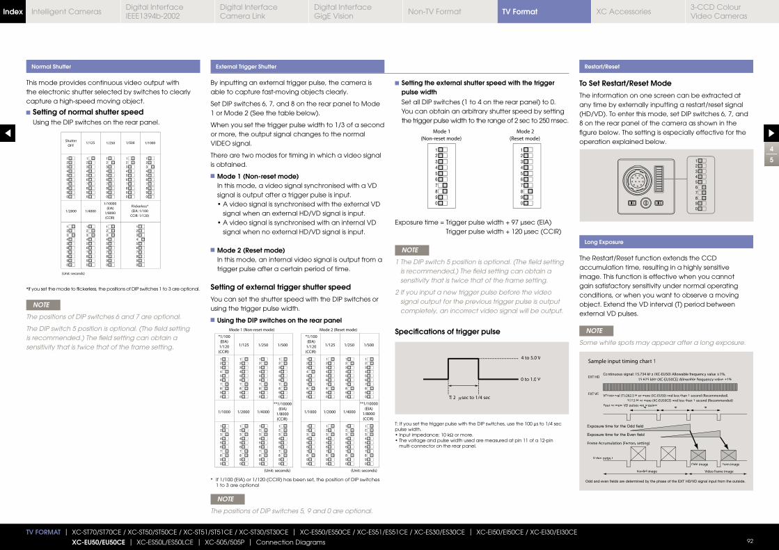
4
5
TV FORMAT | XC-ST70/ST70CE / XC-ST50/ST50CE / XC-ST51/ST51CE / XC-ST30/ST30CE | XC-ES50/ES50CE / XC-ES51/ES51CE / XC-ES30/ES30CE | XC-EI50/EI50CE / XC-EI30/EI30CE
XC-EU50/EU50CE | XC-ES50L/ES50LCE | XC-505/505P | Connection Diagrams 92
By inputting an external trigger pulse, the camera is able to capture fast-moving objects clearly.
Set DIP switches 6, 7, and 8 on the rear panel to Mode 1 or Mode 2 (See the table below).
When you set the trigger pulse width to 1/3 of a second or more, the output signal changes to the normal VIDEO signal.
There are two modes for timing in which a video signal is obtained.
Mode 1 (Non-reset mode) In this mode, a video signal synchronised with a VD signal is output after a trigger pulse is input.
signal when an external HD/VD signal is input.
signal when no external HD/VD signal is input.
Mode 2 (Reset mode) In this mode, an internal video signal is output from a trigger pulse after a certain period of time.
Setting of external trigger shutter speed
You can set the shutter speed with the DIP switches or using the trigger pulse width.
Using the DIP switches on the rear panel
This mode provides continuous video output with the electronic shutter selected by switches to clearly capture a high-speed moving object.
Setting of normal shutter speed Using the DIP switches on the rear panel.
NOTE
The positions of DIP switches 6 and 7 are optional.
The DIP switch 5 position is optional. (The field setting is recommended.) The field setting can obtain a sensitivity that is twice that of the frame setting.
NOTE
The positions of DIP switches 5, 9 and 0 are optional.
NOTE
Some white spots may appear after a long exposure.
Normal Shutter External Trigger Shutter Restart/Reset
Long Exposure
To Set Restart/Reset Mode
The information on one screen can be extracted at any time by externally inputting a restart/reset signal (HD/VD). To enter this mode, set DIP switches 6, 7, and 8 on the rear panel of the camera as shown in the figure below. The setting is especially effective for the operation explained below.
The Restart/Reset function extends the CCD accumulation time, resulting in a highly sensitive image. This function is effective when you cannot gain satisfactory sensitivity under normal operating conditions, or when you want to observe a moving object. Extend the VD interval (T) period between external VD pulses.
Setting the external shutter speed with the trigger pulse width Set all DIP switches (1 to 4 on the rear panel) to 0. You can obtain an arbitrary shutter speed by setting the trigger pulse width to the range of 2 sec to 250 msec.
Trigger pulse width + 120 μsec (CCIR)
NOTE
1 The DIP switch 5 position is optional. (The field setting is recommended.) The field setting can obtain a sensitivity that is twice that of the frame setting.
2 If you input a new trigger pulse before the video signal output for the previous trigger pulse is output completely, an incorrect video signal will be output.
Specifications of trigger pulse
T: If you set the trigger pulse with the DIP switches, use the 100 μs to 1/4 sec pulse width.
Ω or more.
multi-connector on the rear panel.
* If you set the mode to flickerless, the positions of DIP switches 1 to 3 are optional.
* If 1/100 (EIA) or 1/120 (CCIR) has been set, the position of DIP switches 1 to 3 are optional
T: 2 sec to 1/4 sec
4 to 5.0 V
0 to 1.0 VEXT HD
EXT VD
Sample input timing chart 1
Frame Accumulation (Factory setting)
Video frame imageInvalid image
Odd image Even image
Video output
Continuous signal: 15.734 kHz (XC-EU50) Allowable frequency value ±1%,
15.625 kHz (XC-EU50CE) Allowable frequency value ±1%
VD interval (T):262.5 H or more (XC-EU50) and less than 1 second (Recommended),
312.5 H or more (XC-EU50CE) and less than 1 second (Recommended)
Four or more VD pulses are required.
TV FormatIndex Digital Interface IEEE1394b-2002
Digital Interface Camera Link
Digital InterfaceGigE Vision
Non-TV Format XC Accessories3-CCD Colour Video Cameras
Intelligent Cameras

New Dimensions Old Dimensions
5
5
TV FORMAT | XC-ST70/ST70CE / XC-ST50/ST50CE / XC-ST51/ST51CE / XC-ST30/ST30CE | XC-ES50/ES50CE / XC-ES51/ES51CE / XC-ES30/ES30CE | XC-EI50/EI50CE / XC-EI30/EI30CE
XC-EU50/EU50CE | XC-ES50L/ES50LCE | XC-505/505P | Connection Diagrams 93
Information of XC-E Series Console Modification From Janurary 2005, the outside dimensions of XC-E series consoles will be changed to the same dimensions of XC-HR series consoles.
The oustide dimensions will be changed from the following serial number.XC-ES50/ES30 : 250001XC-ES50CE/ES30CE : 550001XC-ES51 : 150001XC-ES51CE : 450001XC-EI50/EI30 : 250001XC-EI50CE/EI30CE : 550001XC-EU50 : 250001XC-EU50CE : 550001
TV FormatIndex Digital Interface IEEE1394b-2002
Digital Interface Camera Link
Digital InterfaceGigE Vision
Non-TV Format XC Accessories3-CCD Colour Video Cameras
Intelligent Cameras
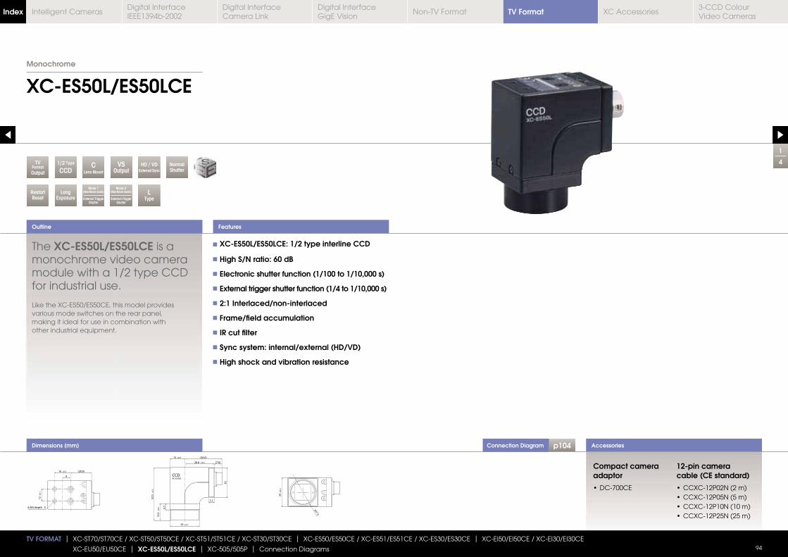
Connection Diagram p104
1
4
XC-ES50L/ES50LCE
Outline
Accessories
TV FORMAT | XC-ST70/ST70CE / XC-ST50/ST50CE / XC-ST51/ST51CE / XC-ST30/ST30CE | XC-ES50/ES50CE / XC-ES51/ES51CE / XC-ES30/ES30CE | XC-EI50/EI50CE / XC-EI30/EI30CE
XC-EU50/EU50CE | XC-ES50L/ES50LCE | XC-505/505P | Connection Diagrams 94
RestartReset
LongExposure
L Type
VSOutput
CLens Mount
TVFormatOutput
Mode 2(Non-Reset mode)
External Trigger Shutter
NormalShutter
HD / VDExternal Sync
Mode 1(Non-Reset mode)
External Trigger Shutter
1/2 Type
CCD
Features
Dimensions (mm)
The XC-ES50L/ES50LCE is a monochrome video camera module with a 1/2 type CCD for industrial use.
Like the XC-ES50/ES50CE, this model provides various mode switches on the rear panel, making it ideal for use in combination with other industrial equipment.
XC-ES50L/ES50LCE: 1/2 type interline CCD
High S/N ratio: 60 dB
Electronic shutter function (1/100 to 1/10,000 s)
External trigger shutter function (1/4 to 1/10,000 s)
2:1 Interlaced/non-interlaced
Frame/field accumulation
IR cut filter
Sync system: internal/external (HD/VD)
High shock and vibration resistance
Compact camera adaptor
12-pin camera cable (CE standard)
Monochrome
TV FormatIndex Digital Interface IEEE1394b-2002
Digital Interface Camera Link
Digital InterfaceGigE Vision
Non-TV Format XC Accessories3-CCD Colour Video Cameras
Intelligent Cameras
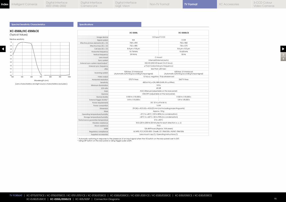
2
4
TV FORMAT | XC-ST70/ST70CE / XC-ST50/ST50CE / XC-ST51/ST51CE / XC-ST30/ST30CE | XC-ES50/ES50CE / XC-ES51/ES51CE / XC-ES30/ES30CE | XC-EI50/EI50CE / XC-EI30/EI30CE
XC-EU50/EU50CE | XC-ES50L/ES50LCE | XC-505/505P | Connection Diagrams 95
Spectral Sensitivity Characteristics Specifications
XC-ES50L XC-ES50LCE
Image device 1/2 type IT CCD
Signal system EIA CCIR
Effective picture elements (H) × (V)
Effective lines (H) × (V)
Cell size (H) × (V)
Horizontal frequency
Vertical frequency
Lens mount C mount
Sync system Internal/External (auto)
External sync system input/output*1 HD/VD (HD/VD level: 2 to 5 Vp-p)
External sync frequency
Jitter less than ±20 nsec
Scanning system525 lines 2:1 Interlaced
(Automatic switching according to input signal)625 lines 2:1 Interlaced
(Automatic switching according to input signal)
Video output 1.0 Vp-p, negative, 75 Ω unbalanced
Horizontal resolution 570 TV lines 560 TV lines
Sensitivity 400 lx F4 (γ
Minimum illumination 3.0 lx
S/N ratio 60 dB
Gain AGC/Manual (adjustable on the rear panel)
Gamma ON/OFF (adjustable on the rear panel)
Normal shutter 1/100 to 1/10,000 s 1/120 to 1/10,000 s
External trigger shutter*2 1/4 to 1/10,000 s 1/4 to 1/8,000 s
Power requirements DC 12 V (+9 to16 V)
Power consumtion 1.6 W
Dimension
Mass Approx. 110 g
Operating temperature/humidity −5˚C to +45˚C / 20 to 80% (no condensation)
Storage temperature/humidity −20˚C to +60˚C / 20 to 95% (no condensation)
Performance guarantee temperature 0 to +40˚C
Vibration resistance
Shock resistance 70 G
MTBF 126,469 hours (Approx. 14.4 years)
Regulatory compliance UL1492, FCC/ICES-003 : ClassB, CE : EN61326, AS/NZ : EN61326
Supplied accessories Lens mount cap (1), Operating instructions (1)
XC-ES50L/XC-ES50LCE(Typical Values)
Relative sensitivity
Wavelength (nm)
(Lens characteristics and light source characteristics excluded.)
*1 Automatic switching in response to the presence of an input signal when the VS switch on the rear panel is set to EXT.*2 Using DIP switch on the rear panel or Using trigger pulse width.
TV FormatIndex Digital Interface IEEE1394b-2002
Digital Interface Camera Link
Digital InterfaceGigE Vision
Non-TV Format XC Accessories3-CCD Colour Video Cameras
Intelligent Cameras
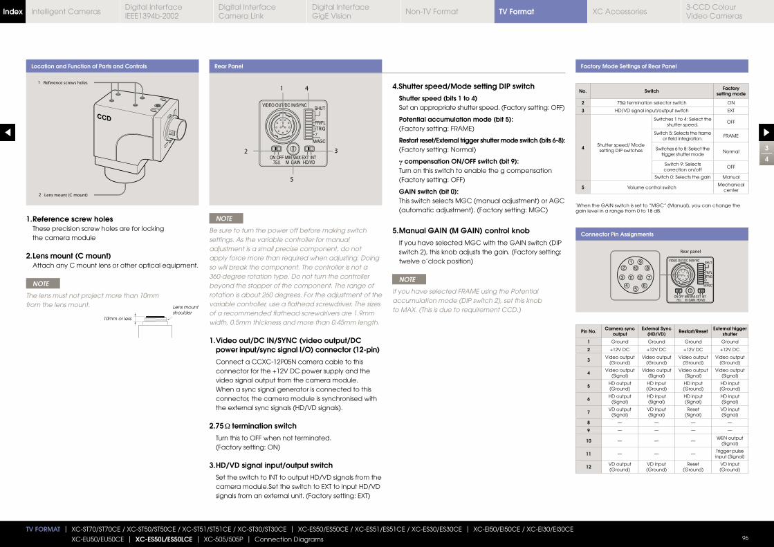
3
4
TV FORMAT | XC-ST70/ST70CE / XC-ST50/ST50CE / XC-ST51/ST51CE / XC-ST30/ST30CE | XC-ES50/ES50CE / XC-ES51/ES51CE / XC-ES30/ES30CE | XC-EI50/EI50CE / XC-EI30/EI30CE
XC-EU50/EU50CE | XC-ES50L/ES50LCE | XC-505/505P | Connection Diagrams 96
Location and Function of Parts and Controls Factory Mode Settings of Rear Panel
Connector Pin Assignments
1. Reference screw holes These precision screw holes are for locking the camera module
2. Lens mount (C mount) Attach any C mount lens or other optical equipment.
NOTE
The lens must not project more than 10mm from the lens mount.
10mm or less
Lens mount shoulder
Pin No. Camera sync output
External Sync (HD/VD) Restart/Reset External trigger
shutter
1 Ground Ground Ground Ground
2 +12V DC +12V DC +12V DC +12V DC
3 Video output (Ground)
Video output (Ground)
Video output (Ground)
Video output (Ground)
4 Video output (Signal)
Video output (Signal)
Video output (Signal)
Video output (Signal)
5 HD output (Ground)
HD input (Ground)
HD input (Ground)
HD input (Ground)
6 HD output (Signal)
HD input (Signal)
HD input (Signal)
HD input (Signal)
7 VD output (Signal)
VD input (Signal)
Reset(Signal)
VD input (Signal)
8 — — — —
9 — — — —
10 — — —WEN output
(Signal)
11 — — —Trigger pulse input (Signal)
12 VD output (Ground)
VD input (Ground)
Reset(Ground)
VD input (Ground)
Rear Panel
NOTE
Be sure to turn the power off before making switch settings. As the variable controller for manual adjustment is a small precise component, do not apply force more than required when adjusting. Doing so will break the component. The controller is not a 360-degree rotation type. Do not turn the controller beyond the stopper of the component. The range of rotation is about 260 degrees. For the adjustment of the variable controller, use a flathead screwdriver. The sizes of a recommended flathead screwdrivers are 1.9mm width, 0.5mm thickness and more than 0.45mm length.
1. Video out/DC IN/SYNC (video output/DC power input/sync signal I/O) connector (12-pin)
Connect a CCXC-12P05N camera cable to this connector for the +12V DC power supply and the video signal output from the camera module. When a sync signal generator is connected to this connector, the camera module is synchronised with the external sync signals (HD/VD signals).
2.75 termination switch
Turn this to OFF when not terminated. (Factory setting: ON)
3. HD/VD signal input/output switch
Set the switch to INT to output HD/VD signals from the camera module.Set the switch to EXT to input HD/VD signals from an external unit. (Factory setting: EXT)
4. Shutter speed/Mode setting DIP switch
Shutter speed (bits 1 to 4) Set an appropriate shutter speed. (Factory setting: OFF)
Potential accumulation mode (bit 5): (Factory setting: FRAME)
Restart reset/External trigger shutter mode switch (bits 6-8): (Factory setting: Normal)
γ compensation ON/OFF switch (bit 9): Turn on this switch to enable the g compensation (Factory setting: OFF)
GAIN switch (bit 0): This switch selects MGC (manual adjustment) or AGC (automatic adjustment). (Factory setting: MGC)
5. Manual GAIN (M GAIN) control knob
If you have selected MGC with the GAIN switch (DIP switch 2), this knob adjusts the gain. (Factory setting: twelve o’clock position)
NOTE
If you have selected FRAME using the Potential accumulation mode (DIP switch 2), set this knob to MAX. (This is due to requirement CCD.)
*When the GAIN switch is set to “MGC” (Manual), you can change the gain level in a range from 0 to 18 dB.
No. Switch Factory setting mode
2 75Ω termination selector switch ON
3 HD/VD signal input/output switch EXT
4 Shutter speed/ Modesetting DIP switches
Switches 1 to 4: Select the shutter speed.
OFF
Switch 5: Selects the frame or field integration.
FRAME
Switches 6 to 8: Select the trigger shutter mode
Normal
Switch 9: Selects correction on/off
OFF
Switch 0: Selects the gain Manual
5 Volume control switchMechanical
center
TV FormatIndex Digital Interface IEEE1394b-2002
Digital Interface Camera Link
Digital InterfaceGigE Vision
Non-TV Format XC Accessories3-CCD Colour Video Cameras
Intelligent Cameras
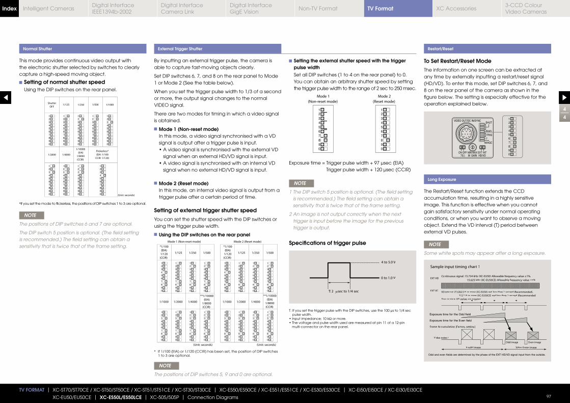
4
4
TV FORMAT | XC-ST70/ST70CE / XC-ST50/ST50CE / XC-ST51/ST51CE / XC-ST30/ST30CE | XC-ES50/ES50CE / XC-ES51/ES51CE / XC-ES30/ES30CE | XC-EI50/EI50CE / XC-EI30/EI30CE
XC-EU50/EU50CE | XC-ES50L/ES50LCE | XC-505/505P | Connection Diagrams 97
By inputting an external trigger pulse, the camera is able to capture fast-moving objects clearly.
Set DIP switches 6, 7, and 8 on the rear panel to Mode 1 or Mode 2 (See the table below).
When you set the trigger pulse width to 1/3 of a second or more, the output signal changes to the normal VIDEO signal.
There are two modes for timing in which a video signal is obtained.
Mode 1 (Non-reset mode) In this mode, a video signal synchronised with a VD signal is output after a trigger pulse is input.
signal when an external HD/VD signal is input.
signal when no external HD/VD signal is input.
Mode 2 (Reset mode) In this mode, an internal video signal is output from a trigger pulse after a certain period of time.
Setting of external trigger shutter speed
You can set the shutter speed with the DIP switches or using the trigger pulse width.
Using the DIP switches on the rear panel
This mode provides continuous video output with the electronic shutter selected by switches to clearly capture a high-speed moving object.
Setting of normal shutter speed Using the DIP switches on the rear panel.
NOTE
The positions of DIP switches 6 and 7 are optional.
The DIP switch 5 position is optional. (The field setting is recommended.) The field setting can obtain a sensitivity that is twice that of the frame setting.
NOTE
The positions of DIP switches 5, 9 and 0 are optional.
NOTE
Some white spots may appear after a long exposure.
Normal Shutter External Trigger Shutter Restart/Reset
Long Exposure
To Set Restart/Reset Mode
The information on one screen can be extracted at any time by externally inputting a restart/reset signal (HD/VD). To enter this mode, set DIP switches 6, 7, and 8 on the rear panel of the camera as shown in the figure below. The setting is especially effective for the operation explained below.
The Restart/Reset function extends the CCD accumulation time, resulting in a highly sensitive image. This function is effective when you cannot gain satisfactory sensitivity under normal operating conditions, or when you want to observe a moving object. Extend the VD interval (T) period between external VD pulses.
Setting the external shutter speed with the trigger pulse width Set all DIP switches (1 to 4 on the rear panel) to 0. You can obtain an arbitrary shutter speed by setting the trigger pulse width to the range of 2 sec to 250 msec.
Trigger pulse width + 120 μsec (CCIR)
NOTE
1 The DIP switch 5 position is optional. (The field setting is recommended.) The field setting can obtain a sensitivity that is twice that of the frame setting.
2 An image is not output correctly when the next trigger is input before the image for the previous trigger is output.
Specifications of trigger pulse
T: If you set the trigger pulse with the DIP switches, use the 100 μs to 1/4 sec pulse width.
Ω or more.
multi-connector on the rear panel.
* If you set the mode to flickerless, the positions of DIP switches 1 to 3 are optional.
* If 1/100 (EIA) or 1/120 (CCIR) has been set, the position of DIP switches 1 to 3 are optional.
T: 2 sec to 1/4 sec
4 to 5.0 V
0 to 1.0 V EXT HD
EXT VD
Sample input timing chart 1
Frame Accumulation (Factory setting)
Video frame imageInvalid image
Odd image Even image
Video output
Continuous signal: 15.734 kHz (XC-EU50) Allowable frequency value ±1%,
15.625 kHz (XC-EU50CE) Allowable frequency value ±1%
VD interval (T):262.5 H or more (XC-EU50) and less than 1 second (Recommended),
312.5 H or more (XC-EU50CE) and less than 1 second (Recommended)
Four or more VD pulses are required.
TV FormatIndex Digital Interface IEEE1394b-2002
Digital Interface Camera Link
Digital InterfaceGigE Vision
Non-TV Format XC Accessories3-CCD Colour Video Cameras
Intelligent Cameras
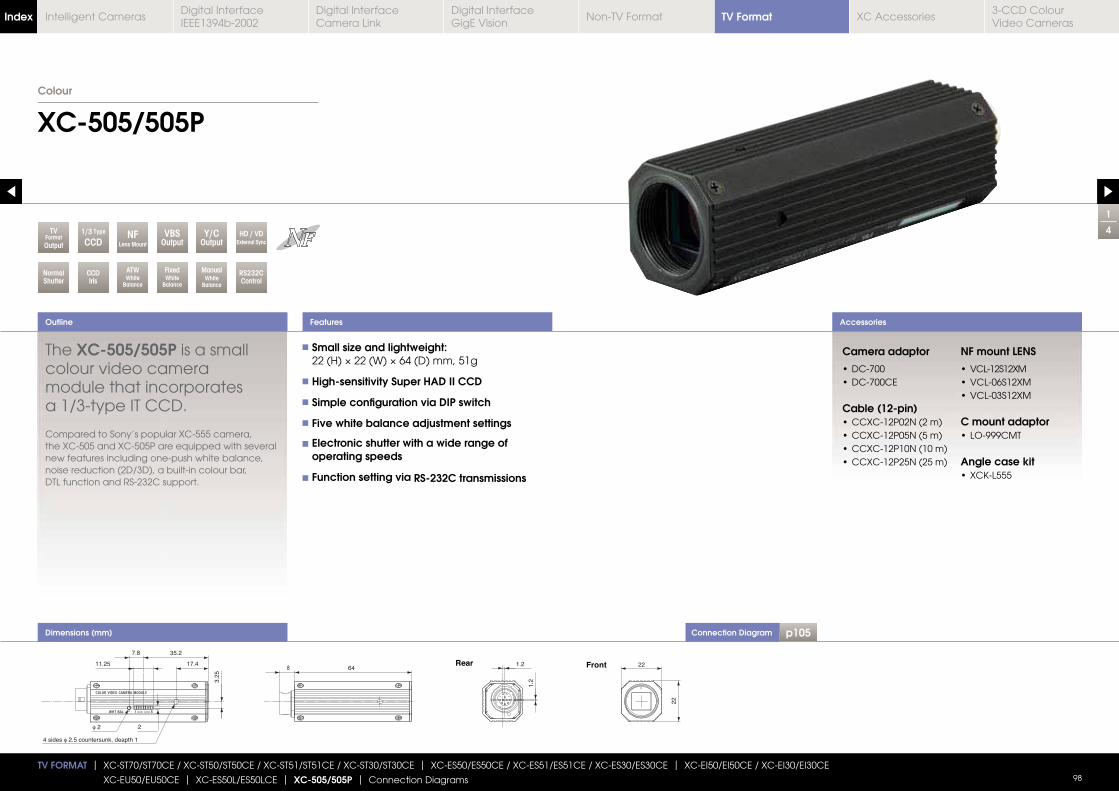
Connection Diagram p105
1
4
XC-505/505P
Outline Accessories
Colour
TV FORMAT | XC-ST70/ST70CE / XC-ST50/ST50CE / XC-ST51/ST51CE / XC-ST30/ST30CE | XC-ES50/ES50CE / XC-ES51/ES51CE / XC-ES30/ES30CE | XC-EI50/EI50CE / XC-EI30/EI30CE
XC-EU50/EU50CE | XC-ES50L/ES50LCE | XC-505/505P | Connection Diagrams 98
NormalShutter
VBSOutput
Y/COutput
ManualWhite
Balance
CCDIris
FixedWhite
Balance
ATWWhite
Balance
RS232CControl
NFLens Mount
TVFormatOutput
HD / VDExternal Sync
1/3 Type
CCD
Features
Dimensions (mm)
The XC-505/505P is a small colour video camera module that incorporates a 1/3-type IT CCD.
Compared to Sony’s popular XC-555 camera, the XC-505 and XC-505P are equipped with several new features including one-push white balance, noise reduction (2D/3D), a built-in colour bar, DTL function and RS-232C support.
Small size and lightweight:
High-sensitivity Super HAD II CCD
Simple configuration via DIP switch
Five white balance adjustment settings
Electronic shutter with a wide range of operating speeds
Function setting via RS-232C transmissions
8 64
7.8
11.25 17.4
35.2
3.25
4 sides 2.5 countersunk, deapth 1
2 2
1.2
1.2
raeR 2222
tnorF
Camera adaptor
Cable (12-pin)
NF mount LENS
C mount adaptor
Angle case kit
TV FormatIndex Digital Interface IEEE1394b-2002
Digital Interface Camera Link
Digital InterfaceGigE Vision
Non-TV Format XC Accessories3-CCD Colour Video Cameras
Intelligent Cameras
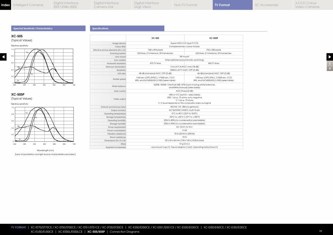
2
4
TV FORMAT | XC-ST70/ST70CE / XC-ST50/ST50CE / XC-ST51/ST51CE / XC-ST30/ST30CE | XC-ES50/ES50CE / XC-ES51/ES51CE / XC-ES30/ES30CE | XC-EI50/EI50CE / XC-EI30/EI30CE
XC-EU50/EU50CE | XC-ES50L/ES50LCE | XC-505/505P | Connection Diagrams 99
Spectral Sensitivity Characteristics Specifications
0
0.2
0.4
0.6
0.8
1.0
Mg
Ye
Gr
Cy
400 450 500 550 600 650 700
0
0.2
0.4
0.6
0.8
1.0
Mg
Ye
Gr
Cy
400 450 500 550 600 650 700
XC-505 XC-505P
Image device Super HAD II 1/3-type IT CCD
Colour filter Complementary colour mosaic
Effective picture elements (H) x (V) 768 x 494 pixels 752 x 582 pixels
Scanning system 525 lines, 2:1 interlace, 30 frames/sec 625 lines, 2:1 interlace, 25 frames/sec
Lens mount NF mount
Sync system Internal/External (automatic switching)
Horizontal resolution 470 TV lines 460 TV lines
Minimum illumination 1.5 lx at F1.4 AGC: max (18 dB)
Sensitivity 2000 lx at F11 AGC: OFF (0 dB)
S/N ratio 48 dB (standard) AGC: OFF (0 dB) 46 dB (standard) AGC: OFF (0 dB)
Shutter speed1/60 sec (OFF) (NTSC), 1/1000 sec, CCD 1/50 sec (OFF) (PAL), 1/1000 sec, CCD
White balanceand MAN (manual) (selectable)
Gain control AGC/Fixed (0 dB)
Video output
VBS or Y/C (switch – selectable)VBS: 1 Vp-p, 75 ohms, sync negative
Y: 1 Vp-p, 75 ohmsC: C level depends on the composite video out signal
External synchronous input HD/VD, VS, VBS (no genlock)
Output connect DC IN/SYNC/VIDEO: multi 12-pin
Operating temperature 0°C to 40°C (32°F to 104°F)
Storage temperature -30°C to +60°C (-22°F to +140°F)
Operating humidity 20% to 80% (no condensation permissible)
Storage humidity 20% to 90% (no condensation permissible)
Power requirement DC 10.5 V to 15 V
Power consumption 1.5 W
Vibration resistance
Shock resistance 70 G
Dimensions (W x H x D) 22 x 22 x 64 mm (7/8 x 7/8 x 2 5/8 inches)
Mass
Supplied Accessories Lens mount cap (1), Tripod adaptor (1 set), Operating instructions (1)
XC-505(Typical Values)
XC-505P(Typical Values)
Relative sensitivity
Relative sensitivity
Wavelength (nm)
(Lens characteristics and light source characteristics excluded.)
TV FormatIndex Digital Interface IEEE1394b-2002
Digital Interface Camera Link
Digital InterfaceGigE Vision
Non-TV Format XC Accessories3-CCD Colour Video Cameras
Intelligent Cameras
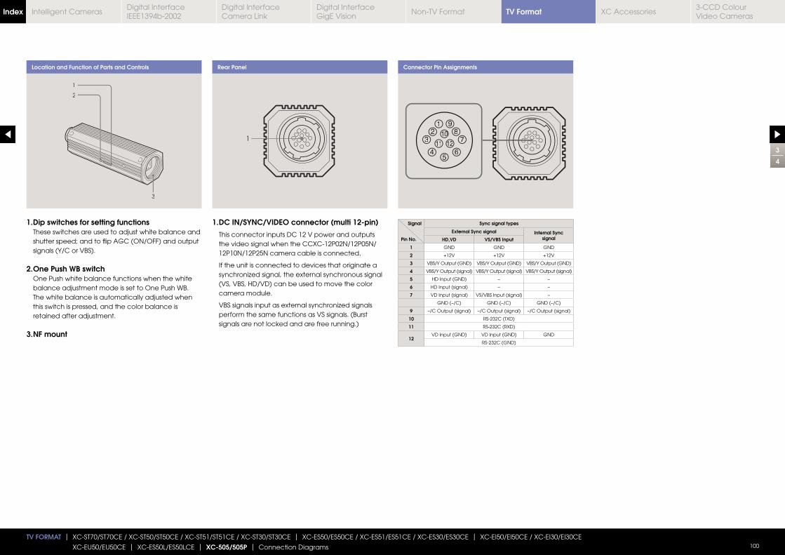
3
4
TV FORMAT | XC-ST70/ST70CE / XC-ST50/ST50CE / XC-ST51/ST51CE / XC-ST30/ST30CE | XC-ES50/ES50CE / XC-ES51/ES51CE / XC-ES30/ES30CE | XC-EI50/EI50CE / XC-EI30/EI30CE
XC-EU50/EU50CE | XC-ES50L/ES50LCE | XC-505/505P | Connection Diagrams 100
Location and Function of Parts and Controls Connector Pin Assignments
1
2
3
12
3
45
6
78
91010
111 1212
1. Dip switches for setting functions These switches are used to adjust white balance and shutter speed; and to flip AGC (ON/OFF) and output signals (Y/C or VBS).
2. One Push WB switch One Push white balance functions when the white balance adjustment mode is set to One Push WB. The white balance is automatically adjusted when this switch is pressed, and the color balance is retained after adjustment.
3. NF mount
Rear Panel
1
1. DC IN/SYNC/VIDEO connector (multi 12-pin)
This connector inputs DC 12 V power and outputs the video signal when the CCXC-12P02N/12P05N/ 12P10N/12P25N camera cable is connected.
If the unit is connected to devices that originate a
(VS, VBS, HD/VD) can be used to move the color camera module.
perform the same functions as VS signals. (Burst signals are not locked and are free running.)
Signal
Pin No.
Sync signal types
External Sync signal Internal Sync signalHD,VD VS/VBS Input
1 GND GND GND
2 +12V +12V +12V
3 VBS/Y Output (GND) VBS/Y Output (GND) VBS/Y Output (GND)
4 VBS/Y Output (signal) VBS/Y Output (signal) VBS/Y Output (signal)
5 HD Input (GND) – –
6 HD Input (signal) – –
7 VD Input (signal) VS/VBS Input (signal) –
GND (–/C) GND (–/C) GND (–/C)
9 –/C Output (signal) –/C Output (signal) –/C Output (signal)
10 RS-232C (TXD)
11 RS-232C (RXD)
12VD Input (GND) VD Input (GND) GND
RS-232C (GND)
TV FormatIndex Digital Interface IEEE1394b-2002
Digital Interface Camera Link
Digital InterfaceGigE Vision
Non-TV Format XC Accessories3-CCD Colour Video Cameras
Intelligent Cameras
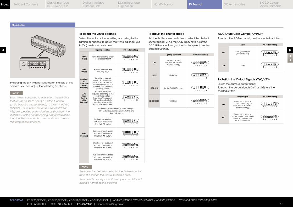
Mode Setting
4
4
TV FORMAT | XC-ST70/ST70CE / XC-ST50/ST50CE / XC-ST51/ST51CE / XC-ST30/ST30CE | XC-ES50/ES50CE / XC-ES51/ES51CE / XC-ES30/ES30CE | XC-EI50/EI50CE / XC-EI30/EI30CE
XC-EU50/EU50CE | XC-ES50L/ES50LCE | XC-505/505P | Connection Diagrams 101
By flipping the DIP switches located on the side of thiscamera, you can adjust the following functions.
NOTE
Each switch is assigned to a function. The switches that should be set to adjust a certain function (white balance, shutter speed), to switch the AGC (ON/OFF), or to switch the output signals (Y/C or VBS) are specified and indicated by shading in the illustrations of the corresponding descriptions of the function. The switches that are not shaded are not related to these functions.
NOTE
The correct white balance is obtained when a white subject is shot on the whole detection area.
The correct color reproduction may not be obtained during a normal scene shooting.
To adjust the white balance
Select the white balance setting according to the lighting conditions. To adjust the white balance, use bitXX (the shaded switches).
To adjust the shutter speed
Set the shutter speed switches to select the desired shutter speed. Using the CCD IRIS function, set the CCD IRIS mode. To adjust the shutter speed, use the shaded switches.
AGC (Auto Gain Control) ON/OFF
To switch the ACG on or off, use the shaded switches.
To Switch the Output Signals (Y/C/VBS)
Select the camera output signal.To switch the output signals (Y/C or VBS), use the shaded switch.
Lighting condition DIP switch setting
3200K (fixed)
For indoor shooting under incandescent light 1 · · · · · · 8
5600K (fixed)
For outdoor shooting on sunny days. 1 · · · · · · 8
One Push WB
(One Pushwhite
balance)
The white balance isautomatically adjustedwhen the One Push WB
switch is pressed, and thecolor balance is retained
after adjustment.
1 · · · · · · 8
ATW(auto
tracingwhite
balance)
The white balance isadjusted according to the
color temperaturetransition of the subject.This mode is suitable forshooting with variable
lighting (factory setting).
1 · · · · · · 8
MAN(manual)
Manual white balance is adjusted using theDIP switches in combination with the One
Push WB switch.
Red hues are subduedwith each press of theOne Push WB switch. 1 · · · · · · 8
Red hues are enhancedwith each press of theOne Push WB switch. 1 · · · · · · 8
Blue hues are subduedwith each press of theOne Push WB switch. 1 · · · · · · 8
Blue hues are enhancedwith each press of theOne Push WB switch. 1 · · · · · · 8
Lighting condition DIP switch setting
OFF1/60 sec. (XC-505)
1/50 sec. (XC-505P)(factory setting) 1 · · · · · · 8
1/1000 1/1,000 sec.1 · · · · · · 8
CCD IRIS Set the CCD IRIS mode. 1 · · · · · · 8
FLICKERLESS 1/100 sec.1 · · · · · · 8
Gain DIP switch setting
ON Auto gain control (factory setting)
1 · · · · · · 8
OFF 0 dB1 · · · · · · 8
Output signal DIP switch setting
VBS
Select this position tooutput the VBS signalfrom the DC IN/VIDEO
(factory setting). 1 · · · · · · 8
Y/C
Select this position tooutput the Y/C separated
signal from the DC IN/VIDEO connector.
1 · · · · · · 8
TV FormatIndex Digital Interface IEEE1394b-2002
Digital Interface Camera Link
Digital InterfaceGigE Vision
Non-TV Format XC Accessories3-CCD Colour Video Cameras
Intelligent Cameras
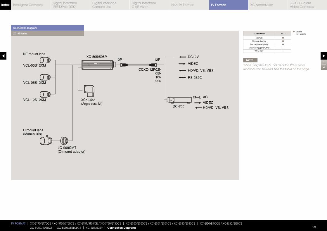
TV FORMAT | XC-ST70/ST70CE / XC-ST50/ST50CE / XC-ST51/ST51CE / XC-ST30/ST30CE | XC-ES50/ES50CE / XC-ES51/ES51CE / XC-ES30/ES30CE | XC-EI50/EI50CE / XC-EI30/EI30CE
XC-EU50/EU50CE | XC-ES50L/ES50LCE | XC-505/505P | Connection Diagrams 102
VCL-12S122XM
VCL-06S122XM
C mount lens(Manual iriss)
LO-999CMT(C-mount adaptor)
12P 12P
CCXC-12P02N05N10N25N
NF mount lens
VCL-03S122XM
DC12DC12VV
VIDEO
DC-700 HD/VD, VS, VBS
AC
VIDEO
XCXC 5-505/505P05/505P
VS, VBHD/VD, V S
RS-232C
XCK-L555(Angle case kit)
Connection Diagram
XC-ST Series
NOTE
When using the JB-77, not all of the XC-ST series functions can be used. See the table on this page.
XC-ST Series JB-77
Normal
Normal shutter
Restart/Reset (R/R)
External trigger shutter –
WEN OUT –
Usable– Not usable
1
4
TV FormatIndex Digital Interface IEEE1394b-2002
Digital Interface Camera Link
Digital InterfaceGigE Vision
Non-TV Format XC Accessories3-CCD Colour Video Cameras
Intelligent Cameras
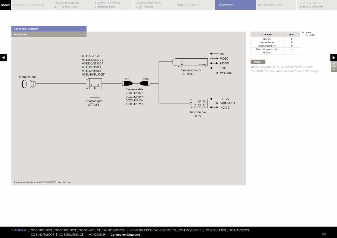
TV FORMAT | XC-ST70/ST70CE / XC-ST50/ST50CE / XC-ST51/ST51CE / XC-ST30/ST30CE | XC-ES50/ES50CE / XC-ES51/ES51CE / XC-ES30/ES30CE | XC-EI50/EI50CE / XC-EI30/EI30CE
XC-EU50/EU50CE | XC-ES50L/ES50LCE | XC-505/505P | Connection Diagrams 103
C mount lens
VIDEO
HD/VD
TRIG
AC
WEN OUT
XC-ES50/ES50CE
XC-ES51/ES51CE
XC-ES30/ES30CE
XC-EI50/EI50CE
XC-EI30/EI30CE
XC-EU50/EU50CE*
Tripod adaptor
VCT -333 I
Camera adaptor
DC-700CE
Camera cable
CCXC-12P02N
CCXC-12P05N
CCXC-12P10N
CCXC-12P25N
12P(F) 12P(M)
DC12V
VIDEO OUT
HD/V D
Junction box
JB-77
Connection Diagram
XC-E Series
NOTE
When using the JB-77, not all of the XC-E series functions can be used. See the table on this page.
XC-E Series JB-77
Normal
Normal shutter
Restart/Reset (R/R)
External trigger shutter –
WEN OUT –
Usable– Not usable
*Recommended lens for XC-EU50/EU50CE : Near UV Lens
2
4
TV FormatIndex Digital Interface IEEE1394b-2002
Digital Interface Camera Link
Digital InterfaceGigE Vision
Non-TV Format XC Accessories3-CCD Colour Video Cameras
Intelligent Cameras
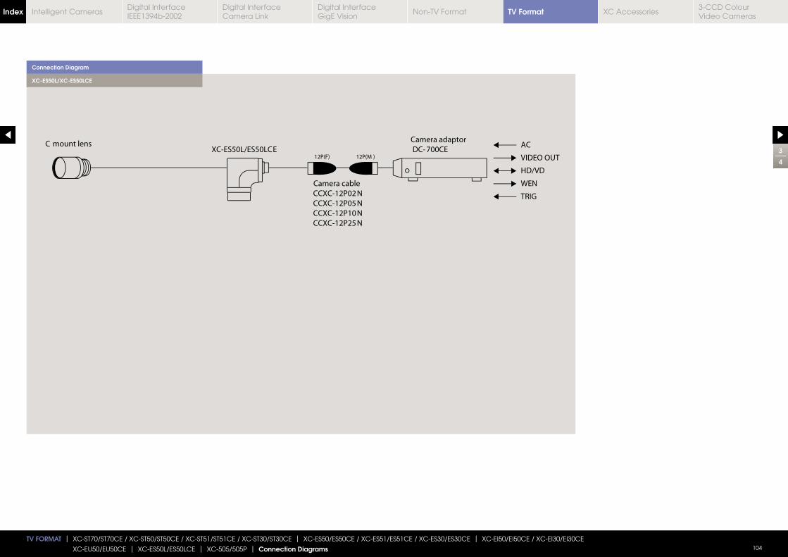
TV FORMAT | XC-ST70/ST70CE / XC-ST50/ST50CE / XC-ST51/ST51CE / XC-ST30/ST30CE | XC-ES50/ES50CE / XC-ES51/ES51CE / XC-ES30/ES30CE | XC-EI50/EI50CE / XC-EI30/EI30CE
XC-EU50/EU50CE | XC-ES50L/ES50LCE | XC-505/505P | Connection Diagrams 104
Connection Diagram
XC-ES50L/XC-ES50LCE
3
4
TV FormatIndex Digital Interface IEEE1394b-2002
Digital Interface Camera Link
Digital InterfaceGigE Vision
Non-TV Format XC Accessories3-CCD Colour Video Cameras
Intelligent Cameras
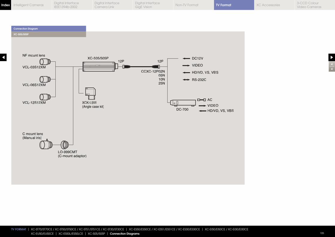
TV FORMAT | XC-ST70/ST70CE / XC-ST50/ST50CE / XC-ST51/ST51CE / XC-ST30/ST30CE | XC-ES50/ES50CE / XC-ES51/ES51CE / XC-ES30/ES30CE | XC-EI50/EI50CE / XC-EI30/EI30CE
XC-EU50/EU50CE | XC-ES50L/ES50LCE | XC-505/505P | Connection Diagrams 105
VCL-12S122XM
VCL-06S122XM
C mount lens(Manual iriss)
LO-999CMT(C-mount adaptor)
12P 12P
CCXC-12P02N05N10N25N
NF mount lens
VCL-03S122XM
DC12DC12VV
VIDEO
DC-700 HD/VD, VS, VBS
AC
VIDEO
XCXC 5-505/505P05/505P
VS, VBHD/VD, V S
RS-232C
XCK-L555(Angle case kit)
Connection Diagram
XC-505/505P
4
4
TV FormatIndex Digital Interface IEEE1394b-2002
Digital Interface Camera Link
Digital InterfaceGigE Vision
Non-TV Format XC Accessories3-CCD Colour Video Cameras
Intelligent Cameras
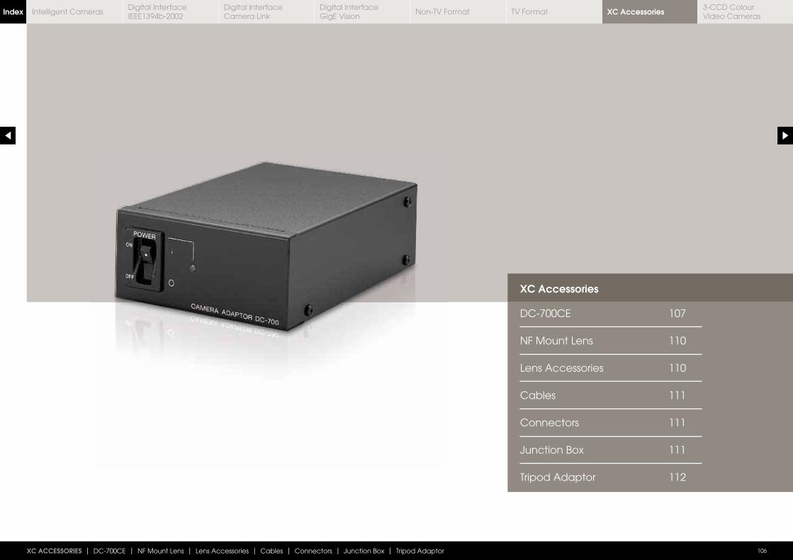
XC Accessories
DC-700CE 107
NF Mount Lens 110
Lens Accessories 110
Cables 111
Connectors 111
Junction Box 111
Tripod Adaptor 112
XC ACCESSORIES | DC-700CE | NF Mount Lens | Lens Accessories | Cables | Connectors | Junction Box | Tripod Adaptor 106
XC AccessoriesIndex Digital Interface IEEE1394b-2002
Digital Interface Camera Link
Digital InterfaceGigE Vision
Non-TV Format TV Format3-CCD Colour Video Cameras
Intelligent Cameras
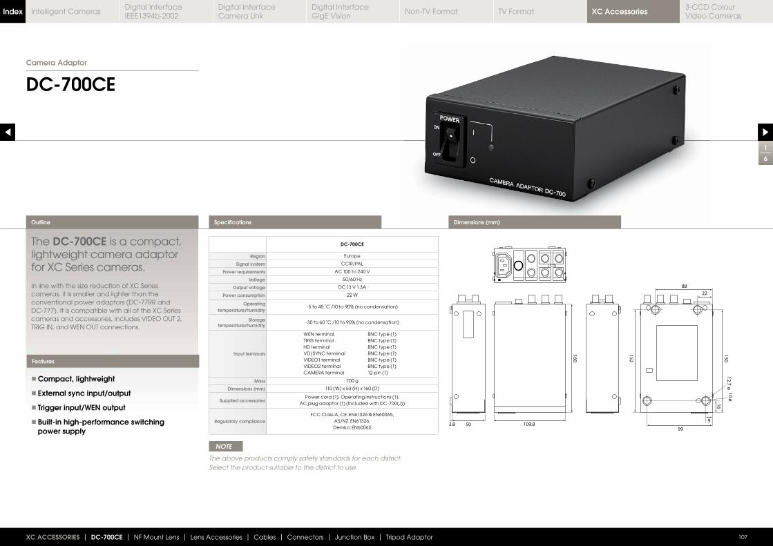
1
6
DC-700CE
The DC-700CE is a compact, lightweight camera adaptor for XC Series cameras.
cameras, it is smaller and lighter than the conventional power adaptors (DC-77RR and DC-777). It is compatible with all of the XC Series cameras and accessories, includes VIDEO OUT 2, TRIG IN, and WEN OUT connections.
Compact, lightweight
External sync input/output
Trigger input/WEN output
Built-in high-performance switching power supply
Outline
107
Features
XC ACCESSORIES | DC-700CE | NF Mount Lens | Lens Accessories | Cables | Connectors | Junction Box | Tripod Adaptor
Dimensions (mm)Specifications
DC-700CE
Region Europe
Signal system CCIR/PAL
Power requirements AC 100 to 240 V
Voltage
Output voltage DC 13 V 1.3A
Power consumption 22 W
Operating temperature/humidity
-5 to 45 ˚C /10 to 90% (no condensation)
Storage temperature/humidity
-30 to 60 ˚C /10 to 90% (no condensation)
Input terminals
WEN terminal BNC type (1) TRIG terminal BNC type (1) HD terminal BNC type (1) VD/SYNC terminal BNC type (1) VIDEO1 terminal BNC type (1) VIDEO2 terminal BNC type (1) CAMERA terminal 12-pin (1)
Mass 700 g
Dimensions (mm) 110 (W) x 53 (H) x 160 (D)
Supplied accessories Power cord (1), Operating instructions (1),
AC plug adaptor (1) (Included with DC-700(J))
Regulatory complianceFCC Class A, CE: EN61326 & EN60065,
AS/NZ: EN61326, Demko: EN60065
Camera Adaptor
NOTE
The above products comply safety standards for each district. Select the product suitable to the district to use.
XC AccessoriesIndex Digital Interface IEEE1394b-2002
Digital Interface Camera Link
Digital InterfaceGigE Vision
Non-TV Format TV Format3-CCD Colour Video Cameras
Intelligent Cameras
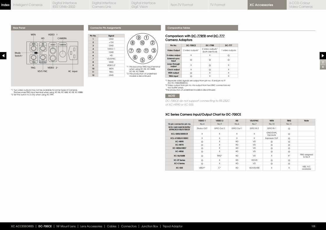
Comparative Tables
2
6
108XC ACCESSORIES | DC-700CE | NF Mount Lens | Lens Accessories | Cables | Connectors | Junction Box | Tripod Adaptor
Rear Panel Connector Pin Assignments
*1 Two video outputs may not be available for some types of cameras. This becomes TRIG input terminal when using, XC-56, XC-56B, XC-55, XC-55BB.
*2 Set the switch to 2 only when using XC-999.
*1 This becomes TRIG input terminal when using XC-55, XC-55BB, XC-56, XC-56BB.
*2 The production of underlined models is discontinued.
*1 Separate video signals are output from pin no. 4 and pin no 9 (for XC-7500/8500CE).
*2 Video output from pin no. 4 is output from two BNC connectors via two buffer amps.
*The production of underlined models is discontinued.
NOTE
DC-700CE do not support connecting to RS-232C of XC-HR90 or XC-555.
XC Series Camera Input/Output Chart for DC-700CE
Pin No. Signal
1 GND
2 +13V
3 GND
4 VIDEO 1
5 GND
6 HD
7 VD/SYNC
8 GND
9 VIDEO 2*
10 WEN
11 TRIG
12 GND
Pin No. DC-700CE DC-77RR DC-777
Video Output 2 video outputs*12 video outputs*2 (both identical)
1 video outputs
S-video output X X oExternal sync
input o o o
Loop-through output X o X
Clock output X o X
WEN output o X X
TRIG input o X X
VIDEO 1 VIDEO 2 HD VD/SYNC WEN TRIG Note
12-pin connector pin no. No.4 No.9 No.6 No.7 No.10 No.11
XCD-V60/V60CR/SX90/ SX90CR/U100/U100CR Strobo OUT GPIO Out 2 GPIO Out 1 GPIO IN 2 GPIO IN 1 o
XCL-5005/5005CR X X X XGND/DVAL Exposure o
XCL-U1000/U1000C X X X X Exposure OUT oXC-HR90 o X HD VD o oXC-HR70 o X HD VD o o
XC-HR50/HR57 o X HD VD o oXC-HR58 o X HD VD o o
XC-56/56BB o TRIG* HD VD X X*TRIG assigned
to No.9
XC-ST Series o X HD VD/VS o oXC-E Series o X HD VD o o
XC-555 VBS/Y* C* HD VD/VS/VBS X XVBS, Y/C available
Comparison with DC-77RFR and DC-777 Camera Adaptors
XC AccessoriesIndex Digital Interface IEEE1394b-2002
Digital Interface Camera Link
Digital InterfaceGigE Vision
Non-TV Format TV Format3-CCD Colour Video Cameras
Intelligent Cameras
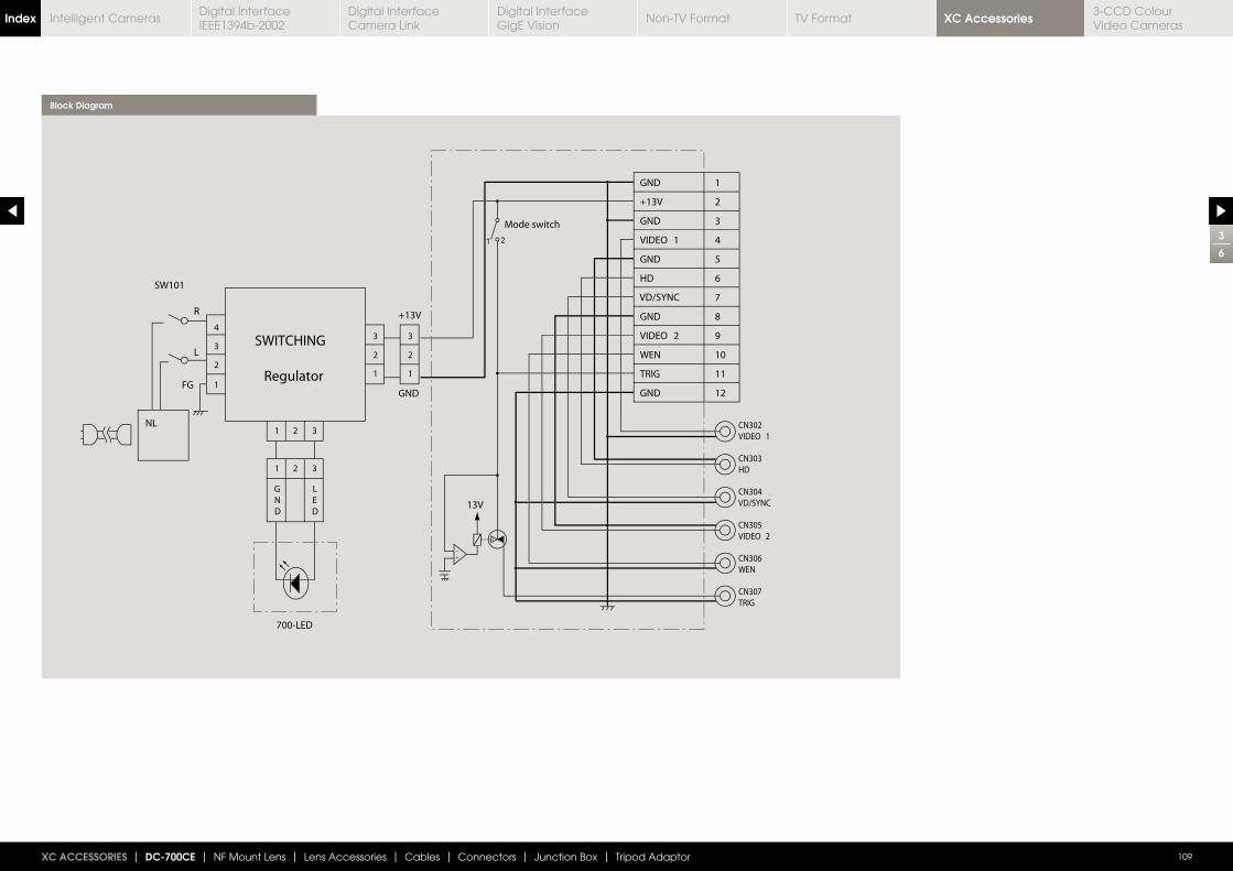
3
6
109XC ACCESSORIES | DC-700CE | NF Mount Lens | Lens Accessories | Cables | Connectors | Junction Box | Tripod Adaptor
Block Diagram
XC AccessoriesIndex Digital Interface IEEE1394b-2002
Digital Interface Camera Link
Digital InterfaceGigE Vision
Non-TV Format TV Format3-CCD Colour Video Cameras
Intelligent Cameras
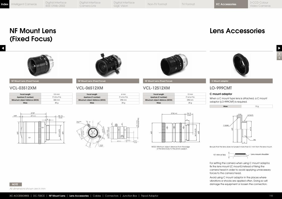
4
6
NF Mount Lens (Fixed Focus)
Lens Accessories
VCL-03S12XM VCL-06S12XM VCL-12S12XM LO-999CMT
NF Mount Lens (Fixed Focus)
110
NF Mount Lens (Fixed Focus) NF Mount Lens (Fixed Focus) C Mount adaptor
XC ACCESSORIES | DC-700CE | NF Mount Lens | Lens Accessories | Cables | Connectors | Junction Box | Tripod Adaptor
Focal Length 3.5 mm
Aperture (F-number) F1.8 to F16
Minumum object distance (MOD) 300 mm
Mass 40 g
Focal Length 6 mm
Aperture (F-number) F1.4 to F16
Minumum object distance (MOD) 298 mm
Mass 25 g
Focal Length 12 mm
Aperture (F-number) F1.4 to F16
Minumum object distance (MOD) 298 mm
Mass 25 g
Mass 12 g
MOD: Minimum object distance from the edge of the lens body to the photo subject.
Be sure that the lens does not project more than 4.1 mm from the lens mount.
C mount adaptor
When a C mount type lens is attached, a C mount adaptor (LO-999CMT) is required.
For setting the camera when using C mount adaptor, fix the lens mount (C mount) instead of fixing the camera head in order to avoid applying unnecessary forces to the camera head.
Avoid using C mount adaptor in the places where vibrations or shocks are applied often. Doing so will damage the equipment or loosen the connection. NOTE
All dimensions shown are in mm
XC AccessoriesIndex Digital Interface IEEE1394b-2002
Digital Interface Camera Link
Digital InterfaceGigE Vision
Non-TV Format TV Format3-CCD Colour Video Cameras
Intelligent Cameras
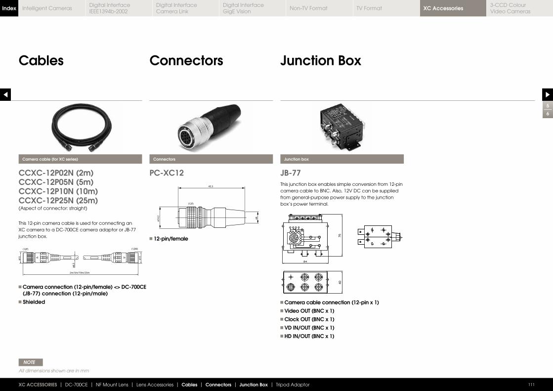
5
6
Cables Connectors
111XC ACCESSORIES | DC-700CE | NF Mount Lens | Lens Accessories | Cables | Connectors | Junction Box | Tripod Adaptor
Junction Box
CCXC-12P02N (2m)CCXC-12P05N (5m)CCXC-12P10N (10m)CCXC-12P25N (25m)(Aspect of connector: straight)
PC-XC12 JB-77
Camera cable (for XC series) Connectors Junction box
This 12-pin camera cable is used for connecting an XC camera to a DC-700CE camera adaptor or JB-77 junction box.
Camera connection (12-pin/female) <> DC-700CE (JB-77) connection (12-pin/male) Shielded Camera cable connection (12-pin x 1)
Video OUT (BNC x 1) Clock OUT (BNC x 1) VD IN/OUT (BNC x 1) HD IN/OUT (BNC x 1)
12-pin/female
This junction box enables simple conversion from 12-pin camera cable to BNC. Also, 12V DC can be supplied from general-purpose power supply to the junction box’s power terminal.
NOTE
All dimensions shown are in mm
XC AccessoriesIndex Digital Interface IEEE1394b-2002
Digital Interface Camera Link
Digital InterfaceGigE Vision
Non-TV Format TV Format3-CCD Colour Video Cameras
Intelligent Cameras
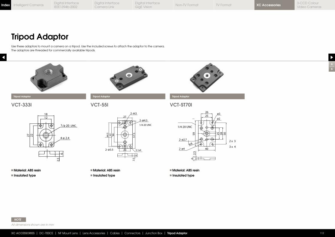
6
6
112XC ACCESSORIES | DC-700CE | NF Mount Lens | Lens Accessories | Cables | Connectors | Junction Box | Tripod Adaptor
Tripod Adaptor
VCT-333I VCT-55I VCT-ST70I
Tripod Adaptor Tripod Adaptor Tripod Adaptor
Material: ABS resin Insulated type
Material: ABS resin Insulated type
Material: ABS resin Insulated type
Use these adaptors to mount a camera on a tripod. Use the included screws to attach the adaptor to the camera. The adaptors are threaded for commercially available tripods.
NOTE
All dimensions shown are in mm
XC AccessoriesIndex Digital Interface IEEE1394b-2002
Digital Interface Camera Link
Digital InterfaceGigE Vision
Non-TV Format TV Format3-CCD Colour Video Cameras
Intelligent Cameras
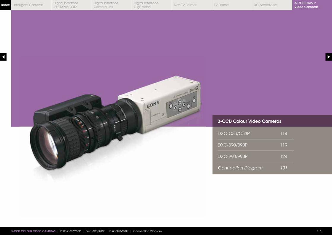
3-CCD Colour Video Cameras
DXC-C33/C33P 114
DXC-390/390P 119
DXC-990/990P 124
Connection Diagram 131
3-CCD COLOUR VIDEO CAMERAS | DXC-C33/C33P | DXC-390/390P | DXC-990/990P | Connection Diagram 113
3-CCD Colour Video CamerasIndex Digital Interface
IEEE1394b-2002Digital Interface Camera Link
Digital InterfaceGigE Vision
Non-TV Format TV Format XC AccessoriesIntelligent Cameras
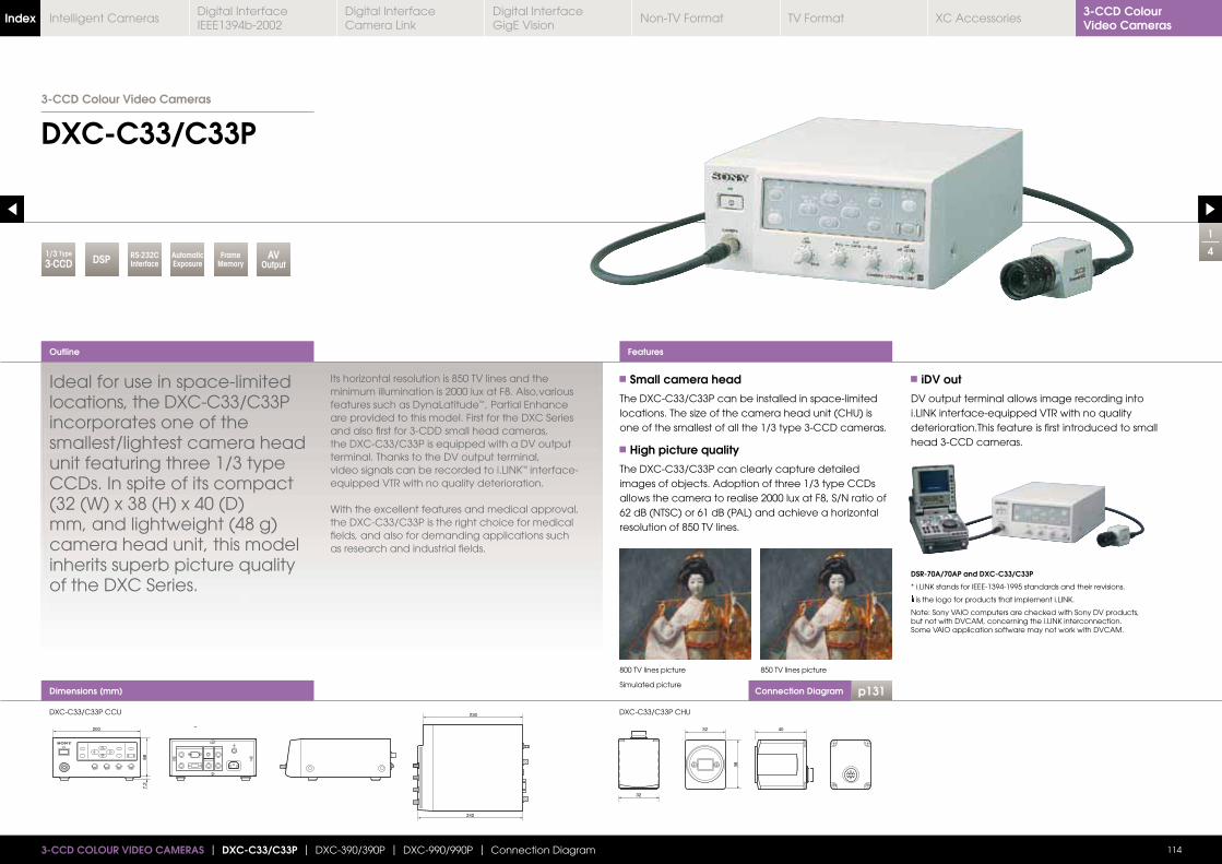
Connection Diagram p131
1/3 Type
3-CCD
1
4
DXC-C33/C33P
1143-CCD COLOUR VIDEO CAMERAS | DXC-C33/C33P | DXC-390/390P | DXC-990/990P | Connection Diagram
Dimensions (mm)
Ideal for use in space-limited locations, the DXC-C33/C33P incorporates one of the smallest/lightest camera head unit featuring three 1/3 type CCDs. In spite of its compact (32 (W) x 38 (H) x 40 (D) mm, and lightweight (48 g) camera head unit, this model inherits superb picture quality of the DXC Series.
minimum illumination is 2000 lux at F8. Also,various features such as DynaLatitude™, Partial Enhance are provided to this model. First for the DXC Series and also first for 3-CDD small head cameras, the DXC-C33/C33P is equipped with a DV output terminal. Thanks to the DV output terminal,
™ interface-equipped VTR with no quality deterioration.
With the excellent features and medical approval, the DXC-C33/C33P is the right choice for medical fields, and also for demanding applications such as research and industrial fields.
Small camera head
The DXC-C33/C33P can be installed in space-limited
one of the smallest of all the 1/3 type 3-CCD cameras.
High picture quality
The DXC-C33/C33P can clearly capture detailed images of objects. Adoption of three 1/3 type CCDs allows the camera to realise 2000 lux at F8, S/N ratio of
resolution of 850 TV lines.
iDV out
DV output terminal allows image recording into
deterioration.This feature is first introduced to small head 3-CCD cameras.
DSR-70A/70AP and DXC-C33/C33P
Note: Sony VAIO computers are checked with Sony DV products,
Some VAIO application software may not work with DVCAM.
Outline Features
800 TV lines picture
Simulated picture
DXC-C33/C33P CCU DXC-C33/C33P CHU
850 TV lines picture
32 4038
32
7.2
88
200
242
230
3-CCD Colour Video Cameras
CCDAV
OutputDSP RS-232CInterface
AutomaticExposure
Frame Memory
3-CCD Colour Video CamerasIndex Digital Interface
IEEE1394b-2002Digital Interface Camera Link
Digital InterfaceGigE Vision
Non-TV Format TV Format XC AccessoriesIntelligent Cameras
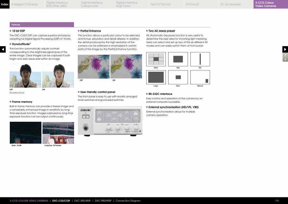
10 bit DSP
The DXC-C33/C33P can capture superior pictures by adopting full Digital Signal Processing (DSP) of 10 bits.
DynaLatitude™
This function automatically adjusts contrast corresponding to the brightness signal level of the entire image. Clear images can be captured if both bright and dark areas exist within an image.
Frame memory
a remarkably enhanced image in sensitivity by long-time exposure function. Images captured by long-time exposure function can be output continuously.
Partial Enhance
This function allows a particular colour to be selected, and its hue, saturation and detail altered. In addition, the detail produced by the high resolution of the camera can be softened or emphasised in certain parts of the image by the Partial Enhance function.
User-friendly control panel
The front panel is easy to use with smartly arranged
Two AE areas preset
AE (Automatic Exposure) function is very useful to determine the best area for incoming light metering. Users can select and set up two of the six different AE modes and can easily switch them at front panel.
RS-232C interface
Easy control and operation of the camera by an external computer is possible.
External synchronisation (HD/VD, VBS)
External synchronisation allows for multiple camera operation.
Features
2
4
OFF
OFF
Gain: 18 dB
ON
ON
Long Exp: 32 frames
1153-CCD COLOUR VIDEO CAMERAS | DXC-C33/C33P | DXC-390/390P | DXC-990/990P | Connection Diagram
Simulated picture
3-CCD Colour Video CamerasIndex Digital Interface
IEEE1394b-2002Digital Interface Camera Link
Digital InterfaceGigE Vision
Non-TV Format TV Format XC AccessoriesIntelligent Cameras
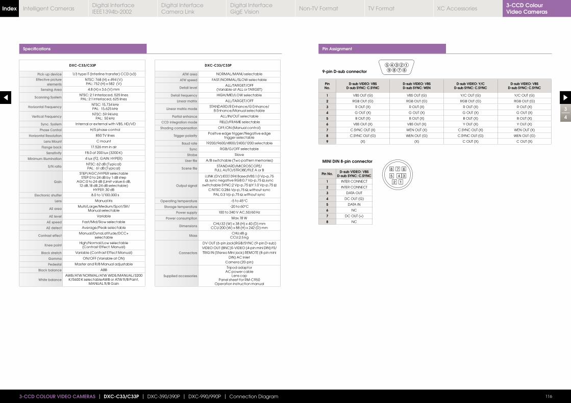
3
4
1163-CCD COLOUR VIDEO CAMERAS | DXC-C33/C33P | DXC-390/390P | DXC-990/990P | Connection Diagram
Specifications Pin Assignment
PinNo.
D-sub VIDEO: VBSD-sub SYNC: C.SYNC
D-sub VIDEO: VBSD-sub SYNC: WEN
D-sub VIDEO: Y/CD-sub SYNC: C.SYNC
D-sub VIDEO: VBSD-sub SYNC: C.SYNC
1 VBS OUT (G) VBS OUT (G) Y/C OUT (G) Y/C OUT (G)
2 RGB OUT (G) RGB OUT (G) RGB OUT (G) RGB OUT (G)
3 R OUT (X) R OUT (X) R OUT (X) R OUT (X)
4 G OUT (X) G OUT (X) G OUT (X) G OUT (X)
5 B OUT (X) B OUT (X) B OUT (X) B OUT (X)
6 VBS OUT (X) VBS OUT (X) Y OUT (X) Y OUT (X)
7 C.SYNC OUT (X) WEN OUT (X) C.SYNC OUT (X) WEN OUT (X)
8 C.SYNC OUT (G) WEN OUT (G) C.SYNC OUT (G) WEN OUT (G)
9 (X) (X) C OUT (X) C OUT (X)
Pin No. D-sub VIDEO: VBSD-sub SYNC: C.SYNC
1 INTER CONNECT
2 INTER CONNECT
3 DATA OUT
4 DC OUT (G)
5 DATA IN
6 NC
7 DC OUT (+)
8 NC
5 4 3 2 19 8 7 6
8 7 6
345
2 1
MINI DIN 8-pin connector
9-pin D-sub connectorDXC-C33/C33P
Pick-up device 1/3 type IT (Interline transfer) CCD (x3)
Effective picture elements
NTSC: 768 (H) x 494 (V)PAL: 752 (H) x 582 (V)
Sensing Area 4.8 (H) x 3.6 (V) mm
Scanning SystemNTSC: 2:1 interlaced, 525 linesPAL: 2:1 interlaced, 625 lines
Horizontal Frequency
Vertical Frequency
Sync. System Internal or external with VBS, HD/VD
Phase Control H/S phase control
Horizontal Resolution 850 TV lines
Lens Mount C mount
Flange back 17.526 mm in air
Sensitivity
Minimum Illumination 4 lux (F2, GAIN: HYPER)
S/N ratioNTSC: 62 dB (Typical)PAL: 61 dB (Typical)
Gain
STEP/AGC/HYPER selectableSTEP:0 to 24 dB by 1 dB step
AGC:0 to 24 dB (Limit value:6 dB,12 dB,18 dB,24 dB selectable)
HYPER: 30 dB
Electronic shutter 8.0 to 1/100,000 s
Lens Manual Iris
AE areaMulti/Large/Medium/Spot/Slit/
Manual selectable
AE level Variable
AE speed Fast/Mid/Slow selectable
AE detect Average/Peak selectable
Contrast effectManual/DynaLatitude/DCC+
selectable
Knee pointHigh/Normal/Low selectable
(Contrast Effect: Manual)
Black stretch Variable (Contrast Effect:Manual)
Gamma ON/OFF (Variable at ON)
Pedestal Master and R/B Manual adjustable
Black balance ABB
White balanceAWB/ATW NORMAL/ATW WIDE/MANUAL/3200
MANUAL R/B Gain
DXC-C33/C33P
ATW area NORMAL/MANU selectable
ATW speed FAST/NORMAL/SLOW selectable
Detail levelALL/TARGET/OFF
(Variable at ALL or TARGET)
Detail frequency HIGH/MID/LOW selectable
Linear matrix ALL/TARGET/OFF
Linear matrix modeSTANDARD/R Enhance/G Enhance/
B Enhance/Manual selectable
Partial enhance ALL/IN/OUT selectable
CCD integration mode FIELD/FRAME selectable
Shading compensation OFF/ON (Manual control)
Trigger polarityPositive edge trigger/Negative edge
trigger selectable
Baud rate 19200/9600/4800/2400/1200 selectable
Sync RGB/G/OFF selectable
Strobe Slave
User file A/B switchable (Two pattern memories)
Scene fileSTANDARD/MICROSCOPE/
FULL AUTO/STROBE/FILE A or B
Output signalΩ, sync negative RGB:0.7 Vp-p,75 Ω,sync
switchable SYNC:2 Vp-p,75 ΩY:1.0 Vp-p,75 Ω C:NTSC 0.286 Vp-p,75 Ω,without sync
PAL 0.3 Vp-p,75 Ω,without sync
Operating temperature -5 to 45°C
Storage temperature -20 to 60°C
Power supply
Power consumption Max.18 W
DimensionsCHU:32 (W) x 38 (H) x 40 (D) mm
CCU:200 (W) x 88 (H) x 242 (D) mm
MassCHU:48 g
CCU:2.5 kg
Connectors
DV OUT (6-pin jack)RGB/SYNC (9-pin D-sub)VIDEO OUT (BNC)S-VIDEO (4-pin mini DIN) FS/TRIG IN (Stereo Mini jack) REMOTE (8-pin mini
DIN) AC InletCamera (20-pin)
Supplied accessories
Tripod adaptorAC power cable
Lens capPanel sheet for RM-C950
Operation instruction manual
3-CCD Colour Video CamerasIndex Digital Interface
IEEE1394b-2002Digital Interface Camera Link
Digital InterfaceGigE Vision
Non-TV Format TV Format XC AccessoriesIntelligent Cameras
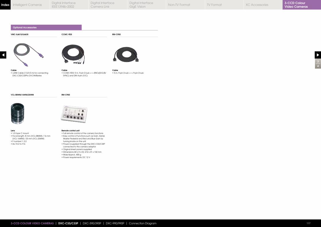
3
4
1173-CCD COLOUR VIDEO CAMERAS | DXC-C33/C33P | DXC-390/390P | DXC-990/990P | Connection Diagram
Optional Accessories
Cable
DXC-C33/C33Pto DVCAMSeries
Cable
SYNC) and DIN 4-pin (Y/C)
Cable
Lens
(VCL-16WM) / 25 mm (VCL-25WM)
Remote control unit
Master Pedestal and Red and Blue Gain by turning knobs on the unit
connected to the camera adaptor
VMC-IL4615/IL4635 CCMC-9DS RM-C950
VCL-08WM/16WM/25WM RM-C950
3-CCD Colour Video CamerasIndex Digital Interface
IEEE1394b-2002Digital Interface Camera Link
Digital InterfaceGigE Vision
Non-TV Format TV Format XC AccessoriesIntelligent Cameras
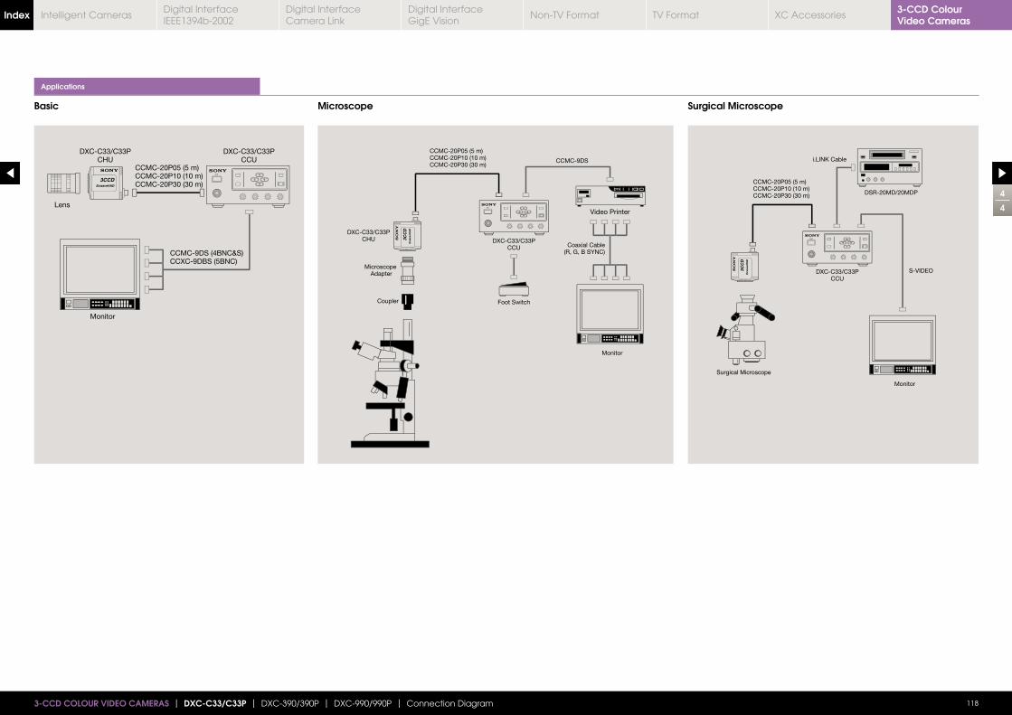
Applications
Basic Microscope Surgical Microscope
4
4
1183-CCD COLOUR VIDEO CAMERAS | DXC-C33/C33P | DXC-390/390P | DXC-990/990P | Connection Diagram
3-CCD Colour Video CamerasIndex Digital Interface
IEEE1394b-2002Digital Interface Camera Link
Digital InterfaceGigE Vision
Non-TV Format TV Format XC AccessoriesIntelligent Cameras
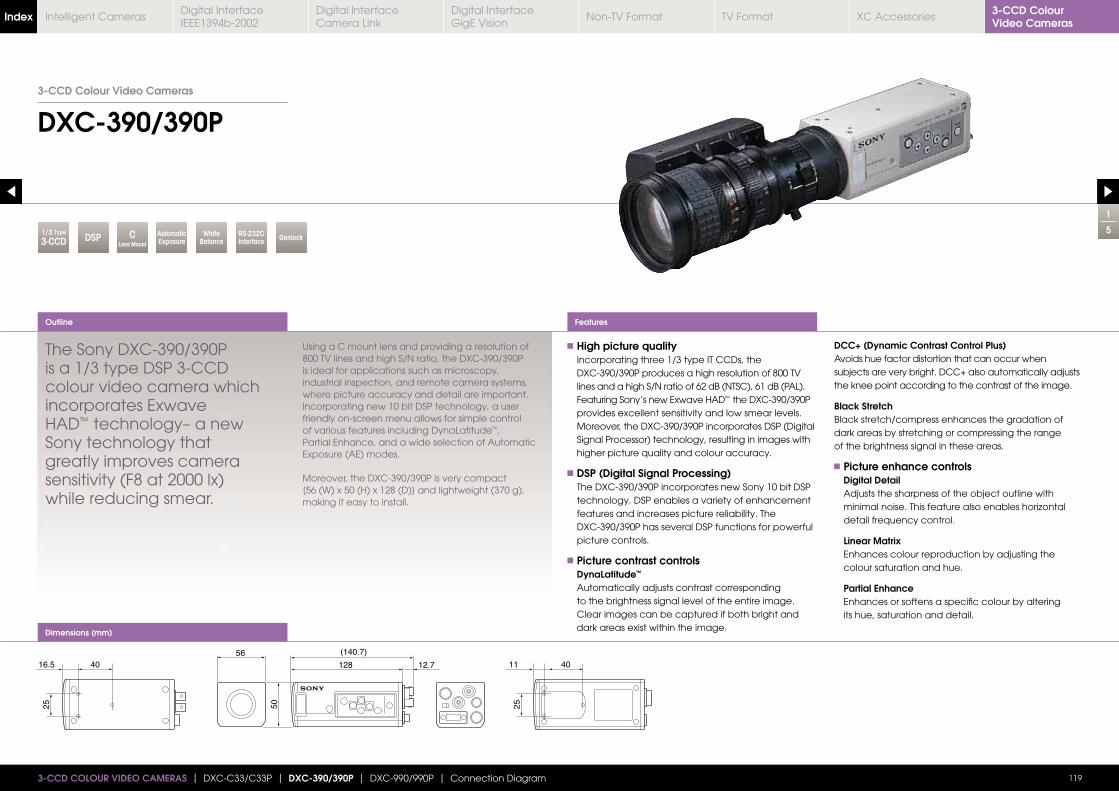
CLens Mount
Dimensions (mm)
1
5
DXC-390/390P
The Sony DXC-390/390P is a 1/3 type DSP 3-CCDcolour video camera which incorporates ExwaveHAD™ technology– a new Sony technology thatgreatly improves camera sensitivity (F8 at 2000 lx)while reducing smear.
Using a C mount lens and providing a resolution of 800 TV lines and high S/N ratio, the DXC-390/390P is ideal for applications such as microscopy, industrial inspection, and remote camera systems, where picture accuracy and detail are important. Incorporating new 10 bit DSP technology, a user friendly on-screen menu allows for simple control of various features including DynaLatitude™, Partial Enhance, and a wide selection of Automatic Exposure (AE) modes.
Moreover, the DXC-390/390P is very compact [56 (W) x 50 (H) x 128 (D)] and lightweight (370 g), making it easy to install.
High picture quality Incorporating three 1/3 type IT CCDs, the DXC-390/390P produces a high resolution of 800 TV lines and a high S/N ratio of 62 dB (NTSC), 61 dB (PAL). Featuring Sony’s new Exwave HAD™ the DXC-390/390P provides excellent sensitivity and low smear levels. Moreover, the DXC-390/390P incorporates DSP (Digital Signal Processor) technology, resulting in images with higher picture quality and colour accuracy.
DSP (Digital Signal Processing) The DXC-390/390P incorporates new Sony 10 bit DSP
technology. DSP enables a variety of enhancement features and increases picture reliability. The DXC-390/390P has several DSP functions for powerful picture controls.
Picture contrast controls DynaLatitude™ Automatically adjusts contrast corresponding to the brightness signal level of the entire image. Clear images can be captured if both bright and dark areas exist within the image.
DCC+ (Dynamic Contrast Control Plus) Avoids hue factor distortion that can occur when subjects are very bright. DCC+ also automatically adjusts the knee point according to the contrast of the image.
Black Stretch Black stretch/compress enhances the gradation of dark areas by stretching or compressing the range of the brightness signal in these areas.
Picture enhance controls Digital Detail
Adjusts the sharpness of the object outline with
detail frequency control.
Linear Matrix Enhances colour reproduction by adjusting the colour saturation and hue.
Partial Enhance Enhances or softens a specific colour by altering its hue, saturation and detail.
Outline
119
Features
3-CCD COLOUR VIDEO CAMERAS | DXC-C33/C33P | DXC-390/390P | DXC-990/990P | Connection Diagram
3-CCD Colour Video Cameras
16.5 40
25
56
50
128 12.7
(140.7)
11 40
25
1/3 Type
3-CCD CCDDSP AutomaticExposure
White Balance
RS-232CInterface Genlock
3-CCD Colour Video CamerasIndex Digital Interface
IEEE1394b-2002Digital Interface Camera Link
Digital InterfaceGigE Vision
Non-TV Format TV Format XC AccessoriesIntelligent Cameras
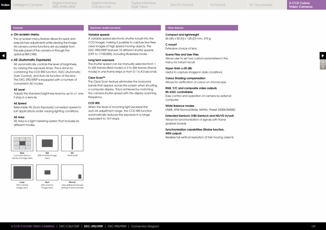
On-screen menu The on-screen menu feature allows for quick and easy picture adjustments while viewing the image. All camera control functions are accessible from the side panel of the camera or through the optional RM-C950.
AE (Automatic Exposure) AE automatically controls the level of brightness by varying the exposure times. This is done by combining the CCD IRIS function, AGC (Automatic Gain Control), and Auto Iris function of the lens. The DXC-390/390P is equipped with a number of convenient AE modes.
AE Level Adjusts the standard brightness level by up to +/- one
F-stop in a lens iris.
AE Speed Selectable AE (Auto Exposure) conversion speed to
suit applications under varying lighting conditions.
AE Area AE Area is a light metering system that includes six
different modes.
Variable speedsA variable speed electronic shutter is built into the CCD imager, making it possible to capture blur-free, clear images of high speed moving objects. The DXC-390/390P features 10 different shutter speeds (OFF to 1/100,000), including flickerless mode.
Long term exposureThe shutter speed can be manually selected from 1 to 255 frames (field mode) or 2 to 256 frames (frame mode) in one-frame steps or from 0.1 to 8.0 seconds.
Clear Scan™
bands that appear across the screen when shooting a computer display. This is achieved by matching the camera shutter speed with the display scanning frequency.
CCD IRISWhen the level of incoming light exceeds the auto iris adjustment range, the CCD IRIS function automatically reduces the exposure in a range equivalent to 10 F-stops.
Compact and lightweight56 (W) x 50 (H) x 128 (D) mm, 370 g
C mountExtensive choice of lens
Scene Files and User FilesAllows user to set two custom parameters in themenu for instant recall
Hyper Gain (+30 dB)Useful to capture images in dark conditions
Colour Shading compensationAllows for verification of colour on microscope
RGB, Y/C and composite video outputsRS-232C controllableEasy control and operation of camera by externalcomputer
White Balance modes
Extended Genlock (VBS Genlock and HD/VD in/out)Allows for synchronisation of signals with framegrabber boards
Synchronisation capabilities (Strobe function, WEN output)Realises full vertical resolution of fast moving objects
Features Electronic shutter functions Other features
2
5
1203-CCD COLOUR VIDEO CAMERAS | DXC-C33/C33P | DXC-390/390P | DXC-990/990P | Connection Diagram
Concentrates on center of image area
75% of entire image area
50% of entire image area
25% of entire image area
Vertical slit
User defined (manual)
3-CCD Colour Video CamerasIndex Digital Interface
IEEE1394b-2002Digital Interface Camera Link
Digital InterfaceGigE Vision
Non-TV Format TV Format XC AccessoriesIntelligent Cameras
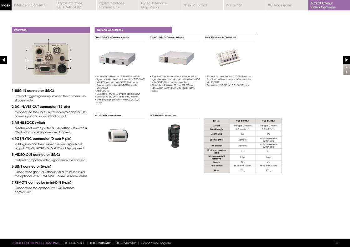
1. TRIG IN connector (BNC)
External trigger signals input when the camera is in strobe mode.
2. DC IN/VBS OUT connector (12-pin)
Connects to the CMA-D2/CE camera adaptor. DC power input and video signal output.
3. MENU LOCK switch
Mechanical switch protects user settings. If switch is ON, buttons on side panel are disabled.
4. RGB/SYNC connector (D-sub 9-pin)
RGB signals and their respective sync signals are output. CCMC-9DS/CCXC- 9DBS cables are used.
5. VIDEO OUT connector (BNC)
Outputs composite video signals from the camera.
6. LENS connector (6-pin)
Connects to general video servo auto iris lenses or
7. REMOTE connector (mini-DIN 8-pin)
Connects to the optional RM-C950 remote control unit.
Rear Panel
3
5
1213-CCD COLOUR VIDEO CAMERAS | DXC-C33/C33P | DXC-390/390P | DXC-990/990P | Connection Diagram
Pin No. VCL-610WEA VCL-614WEA
Mount 1/3 type C mount 1/3 type C mount
Focal length 6.5 to 65 mm 5.5 to 77 mm
Zoom ratio 10x 14x
Zoom control RemoteManual/Remote
switchable
Iris control RemoteManual/Remote
switchable
Maximum aperture ratio 1.4 1.4
Minimum object distance 1.2 m 1.0 m
Macro No Yes
Filter thread
Mass 500 g 900 g
1
2
3
4
6
5
7
Optional Accessories
signal between the adaptor and the DXC-390/P with CCZ-A cable and CCMC-3MZ cable
control unit
cable
signal between the adaptor and the DXC-390/P with CCMC 12-pin multi-core cable
cable
via RS-232C
CMA-D3/D3CE - Camera Adaptor CMA-D2/D2CE - Camera Adaptor RM-C950 - Remote Control Unit
VCL-610WEA - Mount Lens VCL-614WEA - Mount Lens
3-CCD Colour Video CamerasIndex Digital Interface
IEEE1394b-2002Digital Interface Camera Link
Digital InterfaceGigE Vision
Non-TV Format TV Format XC AccessoriesIntelligent Cameras
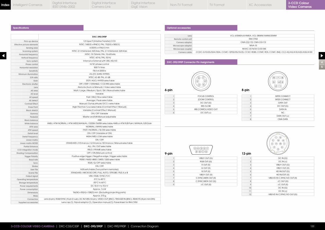
Specifications Optional accessories
DXC-390/390P Connector Pin Assignments
DXC-390/390P
Pick-up device 1/3 type IT (Interline Transfer) CCD
Effective picture elements NTSC: 768(H) x 494(V), PAL: 752(H) x 582(V)
Sensing area 6.00(H) x 4.96(V) mm
Scanning system NTSC: 2:1 interlaced, 525 lines, PAL: 2:1 interlaced, 625 lines
Horizontal frequency
Vertical frequency
Sync system Internal or External with VBS, HD/VD
Phase control H/ SC phase control
Horizontal resolution 800 TV lines
Sensitivity F8.0 at 2000 lx
Minimum illumination 4 lx (F2, GAIN: HYPER)
S/N ratio NTSC: 62 dB, PAL: 61 dB
Gain STEP/ AGC/ HYPER selectable
Electronic shutter OFF / STEP / VARIABLE / CCD IRIS selectable
Lens Remote (Auto or Manual) / Video selectable
AE area Multi / Large / Medium / Spot / Slit / Manual selectable
AE level Variable
AE speed Fast / Mid / Slow selectable
AE detect Average / Peak selectable
Contrast Effect Manual / DynaLatitude/ DCC+ selectable
Knee Point High/ Normal / Low selectable (Contrast Effect: Manual)
Black stretch Variable (Contrast Effect: Manual)
Gamma ON / OFF Variable
Pedestal Master and R/B Manual adjustable
Black balance ABB
White balance
ATW area NORMAL / MANU selectable
ATW speed FAST / NORMAL / SLOW selectable
Detail level ON / OFF (Variable at ON)
Detail Frequency HIGH/ MID/ LOW selectable
Linear matrix ON / OFF
Linear matrix MODE STANDARD / R Enhance / G Enhance / B Enhance / Manual selectable
Partial Enhance ALL / IN / OUT selectable
CCD integration mode FIELD / FRAME selectable
Shading Compensation OFF / ON (Manual control)
Trigger Polarity Positive edge trigger / Negative edge / trigger selectable
Baud rate 19200 / 9600/ 4800 / 2400 / 1200 selectable
Sync RGB / G/ OFF selectable
Strobe ON / OFF
User File A/B switchable (Two pattern memories)
Scene File STANDARD / MICROSCOPE / FULL AUTO / STROBE / FILE A or B
Output signal VBS / RGB / SYNC/Y/C
Operating temperature -5°C to 45°C
Storage temperature -20°C to 60°C
Power requirements DC 10.5 V to 15.0 V
Power consumption Approx. 7.6 W
Dimensions 56(W) x 50(H) x 128(D) mm (Excluding projecting parts)
Mass Approx. 370 g
Connectors Lens (6 pin), RGB/SYNC (9 pin D-sub), DC IN/VBS (12 pin), VIDEO OUT (BNC), TRIGGER IN (BNC), REMOTE (8 pin mini DIN)
Supplied accessories Lens cap (1), Tripod adaptor (1), Operation manual (1), Panel sheet for RM-C950
Lens VCL-610WEA/614WEA, VCL-08WM/16WM/25WM
Remote control unit RM-C950
Camera adaptor CMA-D2/ CE, CMA-D3/ CE
Microscope adaptor MVA-15
Microscope coupler MVAC-33-N/33-O/33-SM
Camera cable CCDC-5/10/25/50A/100A, CCMC-12P02/05/10/25, CCXC-9DBS, CCMC-9DS, CCMC-3MZ, CCZ-A2/A5/A10/A25/A50/A100
4
5
1223-CCD COLOUR VIDEO CAMERAS | DXC-C33/C33P | DXC-390/390P | DXC-990/990P | Connection Diagram
1
5
4 3
2
6
5 4 3 2 1
6789
8
5 4 3
2 1
7 6
1 9
2 10 8
73 11 12
4 65
6-pin
9-pin 12-pin
8-pin
1 FOCUS CONTROL
2 ZOOM CONTROL
3 DC OUT (G)
4 IRIS CLOSE
5 IRIS CONROL/VIDEO OUT
6 DC OUT (+)
1 VBS/Y OUT (G)
2 RGB OUT (G)
3 R OUT (X)
4 G OUT (X)
5 B OUT (X)
6 VBS/Y OUT (X)
7 C.SYNC/WEN OUT (X)
8 C.SYNC/WEN OUT (G)
9 -/C OUT (X)
1 DC IN (G)
2 DC IN (+)
3 VBS/Y OUT (G)
4 VBS/Y OUT (X)
5 HD IN/OUT (G)
6 HD IN/OUT (X)
7 VBS/VD IN C.SYNC/VD OUT (X)
8 -/C OUT (G)
9 -/C OUT (X)
10 DC IN (G)
11 DC IN (+)
12 VBS/VD IN C.SYNC/VD OUT (G)
1 INTER CONNECT
2 INTER CONNECT
3 DATA OUT
4 DC OUT (G)
5 DATA IN
6 NC
7 DATA OUT (+)
8 CMA DATA
3-CCD Colour Video CamerasIndex Digital Interface
IEEE1394b-2002Digital Interface Camera Link
Digital InterfaceGigE Vision
Non-TV Format TV Format XC AccessoriesIntelligent Cameras
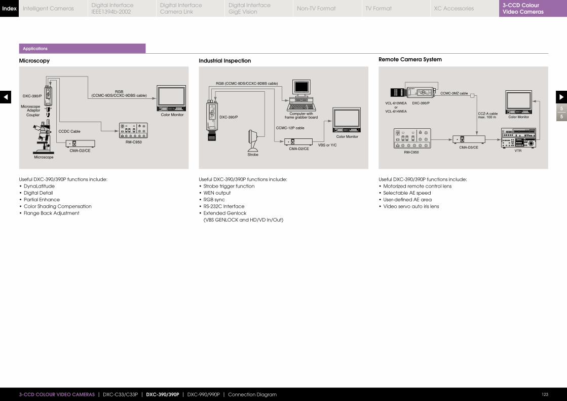
5
5
123
Applications
Microscopy Industrial Inspection Remote Camera System
Useful DXC-390/390P functions include: Useful DXC-390/390P functions include:
Useful DXC-390/390P functions include:
1233-CCD COLOUR VIDEO CAMERAS | DXC-C33/C33P | DXC-390/390P | DXC-990/990P | Connection Diagram
3-CCD Colour Video CamerasIndex Digital Interface
IEEE1394b-2002Digital Interface Camera Link
Digital InterfaceGigE Vision
Non-TV Format TV Format XC AccessoriesIntelligent Cameras
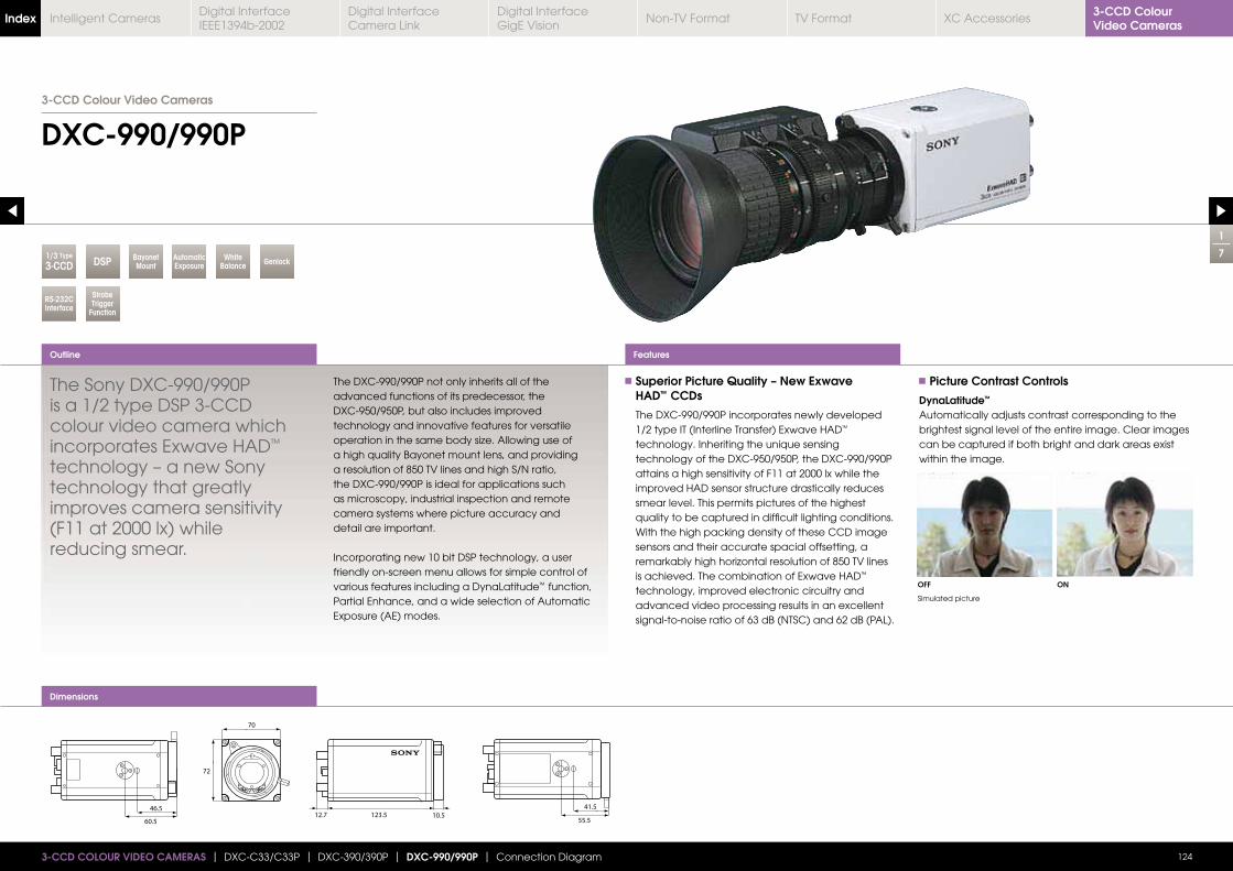
Dimensions
1
7
DXC-990/990P
Outline
124
Features
3-CCD COLOUR VIDEO CAMERAS | DXC-C33/C33P | DXC-390/390P | DXC-990/990P | Connection Diagram
3-CCD Colour Video Cameras
1/3 Type
3-CCD DSP AutomaticExposure
Bayonet Mount
White Balance Genlock
RS-232CInterface
Strobe Trigger
Function
The Sony DXC-990/990P is a 1/2 type DSP 3-CCDcolour video camera whichincorporates Exwave HAD™ technology – a new Sony technology that greatly improves camera sensitivity (F11 at 2000 lx) while reducing smear.
The DXC-990/990P not only inherits all of the advanced functions of its predecessor, the DXC-950/950P, but also includes improved technology and innovative features for versatile
a high quality Bayonet mount lens, and providing a resolution of 850 TV lines and high S/N ratio, the DXC-990/990P is ideal for applications such as microscopy, industrial inspection and remote camera systems where picture accuracy and detail are important.
Incorporating new 10 bit DSP technology, a user friendly on-screen menu allows for simple control of various features including a DynaLatitude™ function, Partial Enhance, and a wide selection of Automatic Exposure (AE) modes.
Superior Picture Quality – New Exwave HAD™ CCDs
The DXC-990/990P incorporates newly developed 1/2 type IT (Interline Transfer) Exwave HAD™ technology. Inheriting the unique sensing technology of the DXC-950/950P, the DXC-990/990P attains a high sensitivity of F11 at 2000 lx while the improved HAD sensor structure drastically reduces smear level. This permits pictures of the highest quality to be captured in difficult lighting conditions. With the high packing density of these CCD image sensors and their accurate spacial offsetting, a
is achieved. The combination of Exwave HAD™
technology, improved electronic circuitry and advanced video processing results in an excellent signal-to-noise ratio of 63 dB (NTSC) and 62 dB (PAL).
Picture Contrast Controls
DynaLatitude™
Automatically adjusts contrast corresponding to the brightest signal level of the entire image. Clear images can be captured if both bright and dark areas existwithin the image.
OFF ON
Simulated picture
3-CCD Colour Video CamerasIndex Digital Interface
IEEE1394b-2002Digital Interface Camera Link
Digital InterfaceGigE Vision
Non-TV Format TV Format XC AccessoriesIntelligent Cameras
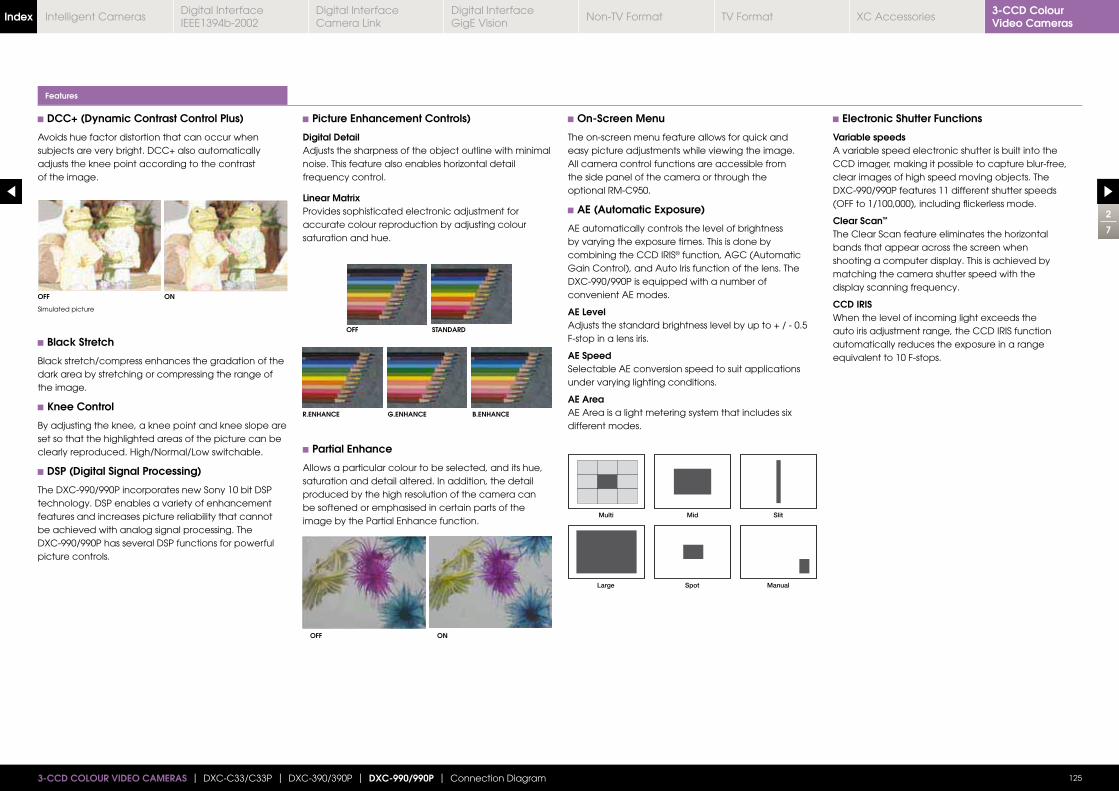
DCC+ (Dynamic Contrast Control Plus)
Avoids hue factor distortion that can occur when subjects are very bright. DCC+ also automatically adjusts the knee point according to the contrast of the image.
Black Stretch
Black stretch/compress enhances the gradation of the dark area by stretching or compressing the range of the image.
Knee Control
By adjusting the knee, a knee point and knee slope are set so that the highlighted areas of the picture can be clearly reproduced. High/Normal/Low switchable.
DSP (Digital Signal Processing)
The DXC-990/990P incorporates new Sony 10 bit DSP technology. DSP enables a variety of enhancement features and increases picture reliability that cannot be achieved with analog signal processing. The DXC-990/990P has several DSP functions for powerful picture controls.
Picture Enhancement Controls)
Digital DetailAdjusts the sharpness of the object outline with minimal
frequency control.
Linear MatrixProvides sophisticated electronic adjustment for accurate colour reproduction by adjusting colour saturation and hue.
Partial Enhance
Allows a particular colour to be selected, and its hue, saturation and detail altered. In addition, the detail produced by the high resolution of the camera canbe softened or emphasised in certain parts of the image by the Partial Enhance function.
On-Screen Menu
The on-screen menu feature allows for quick and easy picture adjustments while viewing the image. All camera control functions are accessible fromthe side panel of the camera or through the optional RM-C950.
AE (Automatic Exposure)
AE automatically controls the level of brightness by varying the exposure times. This is done by combining the CCD IRIS® function, AGC (Automatic Gain Control), and Auto Iris function of the lens. The DXC-990/990P is equipped with a number of convenient AE modes.
AE LevelAdjusts the standard brightness level by up to + / - 0.5 F-stop in a lens iris.
AE SpeedSelectable AE conversion speed to suit applications under varying lighting conditions.
AE AreaAE Area is a light metering system that includes six different modes.
Electronic Shutter Functions
Variable speedsA variable speed electronic shutter is built into the CCD imager, making it possible to capture blur-free, clear images of high speed moving objects. The DXC-990/990P features 11 different shutter speeds (OFF to 1/100,000), including flickerless mode.
Clear Scan™
bands that appear across the screen when shooting a computer display. This is achieved by matching the camera shutter speed with the display scanning frequency.
CCD IRISWhen the level of incoming light exceeds the auto iris adjustment range, the CCD IRIS function automatically reduces the exposure in a range equivalent to 10 F-stops.
Features
2
7
OFF
OFF STANDARD
R.ENHANCE G.ENHANCE B.ENHANCE
OFF
ON
ON
125
Simulated picture
3-CCD COLOUR VIDEO CAMERAS | DXC-C33/C33P | DXC-390/390P | DXC-990/990P | Connection Diagram
3-CCD Colour Video CamerasIndex Digital Interface
IEEE1394b-2002Digital Interface Camera Link
Digital InterfaceGigE Vision
Non-TV Format TV Format XC AccessoriesIntelligent Cameras
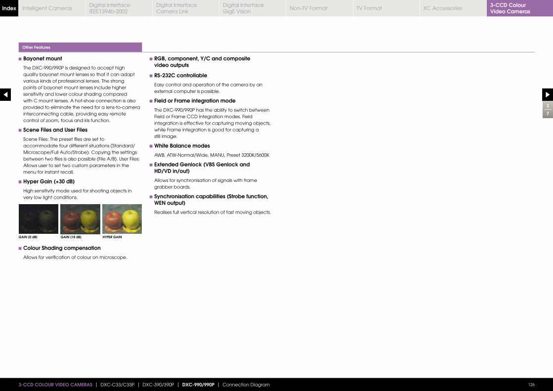
Bayonet mount
The DXC-990/990P is designed to accept high quality bayonet mount lenses so that it can adapt various kinds of professional lenses. The strong points of bayonet mount lenses include higher sensitivity and lower colour shading compared with C mount lenses. A hot-shoe connection is also provided to eliminate the need for a lens-to-camera interconnecting cable, providing easy remote
Scene Files and User Files
Scene Files: The preset files are set to accommodate four different situations (Standard/Microscope/Full Auto/Strobe). Copying the settings between two files is also possible (File A/B). User Files: Allows user to set two custom parameters in the menu for instant recall.
Hyper Gain (+30 dB)
High sensitivity mode used for shooting objects in very low light conditions.
Colour Shading compensation
Allows for verification of colour on microscope.
RGB, component, Y/C and composite video outputs
RS-232C controllable
Easy control and operation of the camera by an external computer is possible.
Field or Frame integration mode
The DXC-990/990P has the ability to switch between Field or Frame CCD integration modes. Field integration is effective for capturing moving objects, while Frame integration is good for capturing a still image.
White Balance modes
Extended Genlock (VBS Genlock and HD/VD in/out)
Allows for synchronisation of signals with frame grabber boards.
Synchronisation capabilities (Strobe function, WEN output)
Realises full vertical resolution of fast moving objects.
Other Features
3
7
GAIN (0 dB) GAIN (18 dB) HYPER GAIN
1263-CCD COLOUR VIDEO CAMERAS | DXC-C33/C33P | DXC-390/390P | DXC-990/990P | Connection Diagram
3-CCD Colour Video CamerasIndex Digital Interface
IEEE1394b-2002Digital Interface Camera Link
Digital InterfaceGigE Vision
Non-TV Format TV Format XC AccessoriesIntelligent Cameras
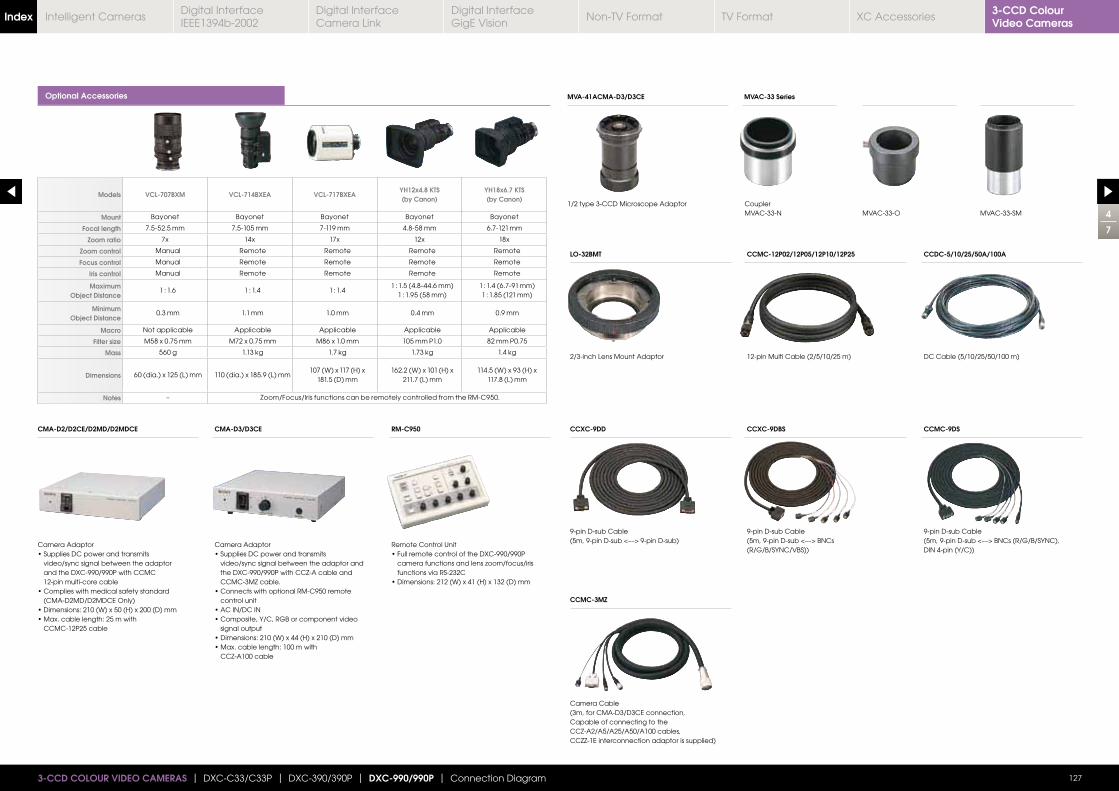
4
7
1273-CCD COLOUR VIDEO CAMERAS | DXC-C33/C33P | DXC-390/390P | DXC-990/990P | Connection Diagram
Optional Accessories
Models VCL-707BXM VCL-714BXEA VCL-717BXEAYH12x4.8 KTS(by Canon)
YH18x6.7 KTS(by Canon)
Mount Bayonet Bayonet Bayonet Bayonet Bayonet
Focal length 7.5-52.5 mm 7.5-105 mm 7-119 mm 4.8-58 mm 6.7-121 mm
Zoom ratio 7x 14x 17x 12x 18x
Zoom control Manual Remote Remote Remote Remote
Focus control Manual Remote Remote Remote Remote
Iris control Manual Remote Remote Remote Remote
MaximumObject Distance
1 : 1.6 1 : 1.4 1 : 1.41 : 1.5 (4.8-44.6 mm)
1 : 1.95 (58 mm)1 : 1.4 (6.7-91 mm)1 : 1.85 (121 mm)
MinimumObject Distance
0.3 mm 1.1 mm 1.0 mm 0.4 mm 0.9 mm
Macro Not applicable Applicable Applicable Applicable Applicable
Filter size M58 x 0.75 mm M72 x 0.75 mm M86 x 1.0 mm 105 mm P1.0 82 mm P0.75
Mass 560 g 1.13 kg 1.7 kg 1.73 kg 1.4 kg
Dimensions 60 (dia.) x 125 (L) mm 110 (dia.) x 185.9 (L) mm107 (W) x 117 (H) x
181.5 (D) mm 162.2 (W) x 101 (H) x
211.7 (L) mm 114.5 (W) x 93 (H) x
117.8 (L) mm
Notes – Zoom/Focus/Iris functions can be remotely controlled from the RM-C950.
2/3-inch Lens Mount Adaptor 12-pin Multi Cable (2/5/10/25 m) DC Cable (5/10/25/50/100 m)
9-pin D-sub Cable 9-pin D-sub Cable
(R/G/B/SYNC/VBS))
9-pin D-sub Cable
DIN 4-pin (Y/C))
Camera Cable(3m, for CMA-D3/D3CE connection, Capable of connecting to theCCZ-A2/A5/A25/A50/A100 cables,CCZZ-1E interconnection adaptor is supplied)
1/2 type 3-CCD Microscope Adaptor CouplerMVAC-33-N MVAC-33-O MVAC-33-SM
LO-32BMT CCMC-12P02/12P05/12P10/12P25 CCDC-5/10/25/50A/100A
CCXC-9DD CCXC-9DBS CCMC-9DS
CCMC-3MZ
MVA-41ACMA-D3/D3CE MVAC-33 Series
Camera Adaptor
video/sync signal between the adaptor and the DXC-990/990P with CCMC 12-pin multi-core cable
(CMA-D2MD/D2MDCE Only)
CCMC-12P25 cable
Camera Adaptor
video/sync signal between the adaptor and the DXC-990/990P with CCZ-A cable and CCMC-3MZ cable.
control unit
signal output
CCZ-A100 cable
Remote Control Unit
functions via RS-232C
CMA-D2/D2CE/D2MD/D2MDCE CMA-D3/D3CE RM-C950
3-CCD Colour Video CamerasIndex Digital Interface
IEEE1394b-2002Digital Interface Camera Link
Digital InterfaceGigE Vision
Non-TV Format TV Format XC AccessoriesIntelligent Cameras
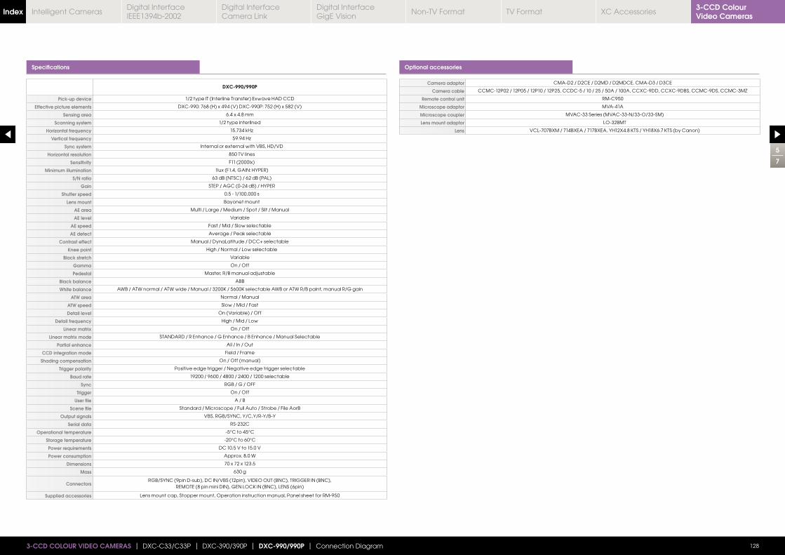
5
7
1283-CCD COLOUR VIDEO CAMERAS | DXC-C33/C33P | DXC-390/390P | DXC-990/990P | Connection Diagram
Specifications Optional accessories
DXC-990/990P
Pick-up device 1/2 type IT (Interline Transfer) Exwave HAD CCD
Effective picture elements DXC-990: 768 (H) x 494 (V) DXC-990P: 752 (H) x 582 (V)
Sensing area 6.4 x 4.8 mm
Scanning system 1/2 type interlined
Horizontal frequency
Vertical frequency
Sync system Internal or external with VBS, HD/VD
Horizontal resolution 850 TV lines
Sensitivity F11 (2000lx)
Minimum illumination 1lux (F1.4, GAIN: HYPER)
S/N ratio 63 dB (NTSC) / 62 dB (PAL)
Gain STEP / AGC (0-24 dB) / HYPER
Shutter speed 0.5 - 1/100,000 s
Lens mount Bayonet mount
AE area Multi / Large / Medium / Spot / Slit / Manual
AE level Variable
AE speed Fast / Mid / Slow selectable
AE detect Average / Peak selectable
Contrast effect Manual / DynaLatitude / DCC+ selectable
Knee point High / Normal / Low selectable
Black stretch Variable
Gamma On / Off
Pedestal Master, R/B manual adjustable
Black balance ABB
White balance
ATW area Normal / Manual
ATW speed Slow / Mid / Fast
Detail level On (Variable) / Off
Detail frequency High / Mid / Low
Linear matrix On / Off
Linear matrix mode STANDARD / R Enhance / G Enhance / B Enhance / Manual Selectable
Partial enhance All / In / Out
CCD integration mode Field / Frame
Shading compensation On / Off (manual)
Trigger polarity Positive edge trigger / Negative edge trigger selectable
Baud rate 19200 / 9600 / 4800 / 2400 / 1200 selectable
Sync RGB / G / OFF
Trigger On / Off
User file A / B
Scene file Standard / Microscope / Full Auto / Strobe / File AorB
Output signals VBS, RGB/SYNC, Y/C,Y/R-Y/B-Y
Serial data RS-232C
Operational temperature -5°C to 45°C
Storage temperature -20°C to 60°C
Power requirements DC 10.5 V to 15.0 V
Power consumption Approx. 8.0 W
Dimensions 70 x 72 x 123.5
Mass 630 g
ConnectorsRGB/SYNC (9pin D-sub), DC IN/VBS (12pin), VIDEO OUT (BNC), TRIGGER IN (BNC),
Supplied accessories Lens mount cap, Stopper mount, Operation instruction manual, Panel sheet for RM-950
Camera adaptor CMA-D2 / D2CE / D2MD / D2MDCE, CMA-D3 / D3CE
Camera cable CCMC-12P02 / 12P05 / 12P10 / 12P25, CCDC-5 / 10 / 25 / 50A / 100A, CCXC-9DD, CCXC-9DBS, CCMC-9DS, CCMC-3MZ
Remote control unit RM-C950
Microscope adaptor MVA-41A
Microscope coupler MVAC-33 Series (MVAC-33-N/33-O/33-SM)
Lens mount adaptor LO-32BMT
Lens
3-CCD Colour Video CamerasIndex Digital Interface
IEEE1394b-2002Digital Interface Camera Link
Digital InterfaceGigE Vision
Non-TV Format TV Format XC AccessoriesIntelligent Cameras
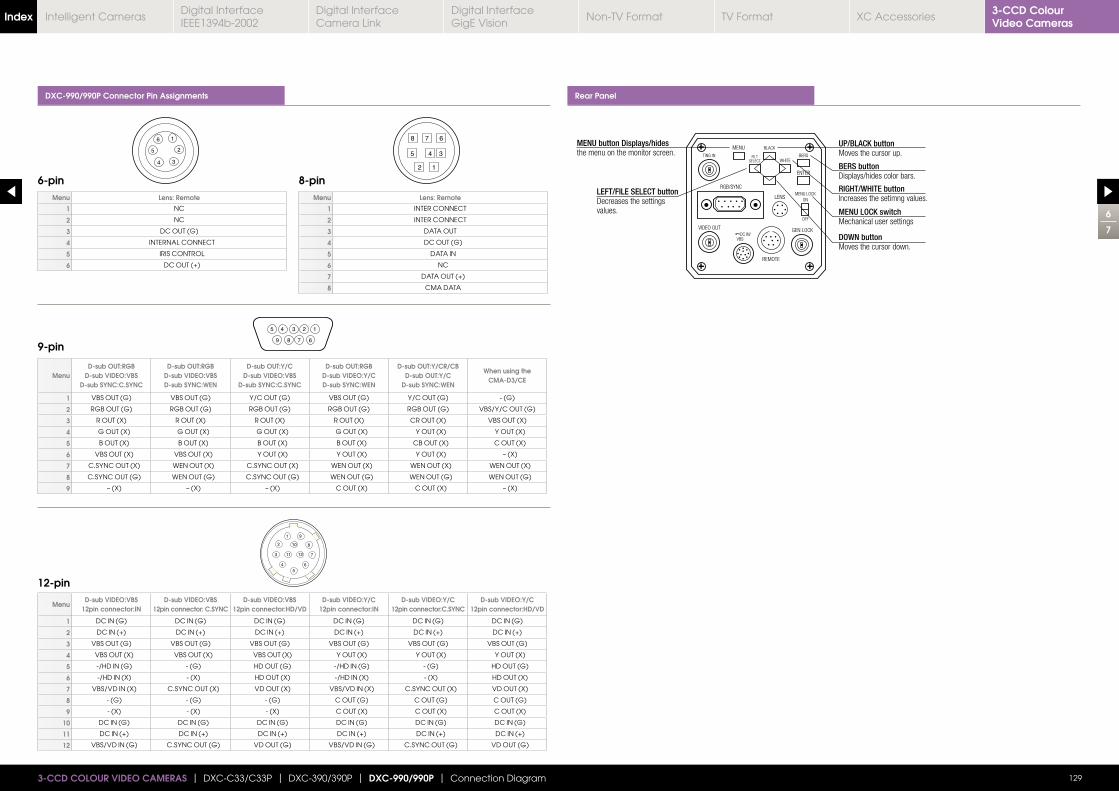
DXC-990/990P Connector Pin Assignments Rear Panel
Menu Lens: Remote
1 NC
2 NC
3 DC OUT (G)
4 INTERNAL CONNECT
5 IRIS CONTROL
6 DC OUT (+)
MenuD-sub VIDEO:VBS
12pin connector:IND-sub VIDEO:VBS
12pin connector: C.SYNCD-sub VIDEO:VBS
12pin connector:HD/VDD-sub VIDEO:Y/C
12pin connector:IND-sub VIDEO:Y/C
12pin connector:C.SYNCD-sub VIDEO:Y/C
12pin connector:HD/VD
1 DC IN (G) DC IN (G) DC IN (G) DC IN (G) DC IN (G) DC IN (G)
2 DC IN (+) DC IN (+) DC IN (+) DC IN (+) DC IN (+) DC IN (+)
3 VBS OUT (G) VBS OUT (G) VBS OUT (G) VBS OUT (G) VBS OUT (G) VBS OUT (G)
4 VBS OUT (X) VBS OUT (X) VBS OUT (X) Y OUT (X) Y OUT (X) Y OUT (X)
5 -/HD IN (G) - (G) HD OUT (G) -/HD IN (G) - (G) HD OUT (G)
6 -/HD IN (X) - (X) HD OUT (X) -/HD IN (X) - (X) HD OUT (X)
7 VBS/VD IN (X) C.SYNC OUT (X) VD OUT (X) VBS/VD IN (X) C.SYNC OUT (X) VD OUT (X)
8 - (G) - (G) - (G) C OUT (G) C OUT (G) C OUT (G)
9 - (X) - (X) - (X) C OUT (X) C OUT (X) C OUT (X)
10 DC IN (G) DC IN (G) DC IN (G) DC IN (G) DC IN (G) DC IN (G)
11 DC IN (+) DC IN (+) DC IN (+) DC IN (+) DC IN (+) DC IN (+)
12 VBS/VD IN (G) C.SYNC OUT (G) VD OUT (G) VBS/VD IN (G) C.SYNC OUT (G) VD OUT (G)
Menu Lens: Remote
1 INTER CONNECT
2 INTER CONNECT
3 DATA OUT
4 DC OUT (G)
5 DATA IN
6 NC
7 DATA OUT (+)
8 CMA DATA
6-pin
9-pin
12-pin
8-pin
1
5
4 3
2
6
5 4 3 2 1
6789
8
5 4 3
2 1
7 6
1 9
2 10 8
73 11 12
4 65
6
7
1293-CCD COLOUR VIDEO CAMERAS | DXC-C33/C33P | DXC-390/390P | DXC-990/990P | Connection Diagram
MenuD-sub OUT:RGB
D-sub VIDEO:VBSD-sub SYNC:C.SYNC
D-sub OUT:RGBD-sub VIDEO:VBSD-sub SYNC:WEN
D-sub OUT:Y/CD-sub VIDEO:VBS
D-sub SYNC:C.SYNC
D-sub OUT:RGBD-sub VIDEO:Y/CD-sub SYNC:WEN
D-sub OUT:Y/CR/CBD-sub OUT:Y/C
D-sub SYNC:WEN
When using theCMA-D3/CE
1 VBS OUT (G) VBS OUT (G) Y/C OUT (G) VBS OUT (G) Y/C OUT (G) - (G)
2 RGB OUT (G) RGB OUT (G) RGB OUT (G) RGB OUT (G) RGB OUT (G) VBS/Y/C OUT (G)
3 R OUT (X) R OUT (X) R OUT (X) R OUT (X) CR OUT (X) VBS OUT (X)
4 G OUT (X) G OUT (X) G OUT (X) G OUT (X) Y OUT (X) Y OUT (X)
5 B OUT (X) B OUT (X) B OUT (X) B OUT (X) CB OUT (X) C OUT (X)
6 VBS OUT (X) VBS OUT (X) Y OUT (X) Y OUT (X) Y OUT (X) – (X)
7 C.SYNC OUT (X) WEN OUT (X) C.SYNC OUT (X) WEN OUT (X) WEN OUT (X) WEN OUT (X)
8 C.SYNC OUT (G) WEN OUT (G) C.SYNC OUT (G) WEN OUT (G) WEN OUT (G) WEN OUT (G)
9 – (X) – (X) – (X) C OUT (X) C OUT (X) – (X)
3-CCD Colour Video CamerasIndex Digital Interface
IEEE1394b-2002Digital Interface Camera Link
Digital InterfaceGigE Vision
Non-TV Format TV Format XC AccessoriesIntelligent Cameras
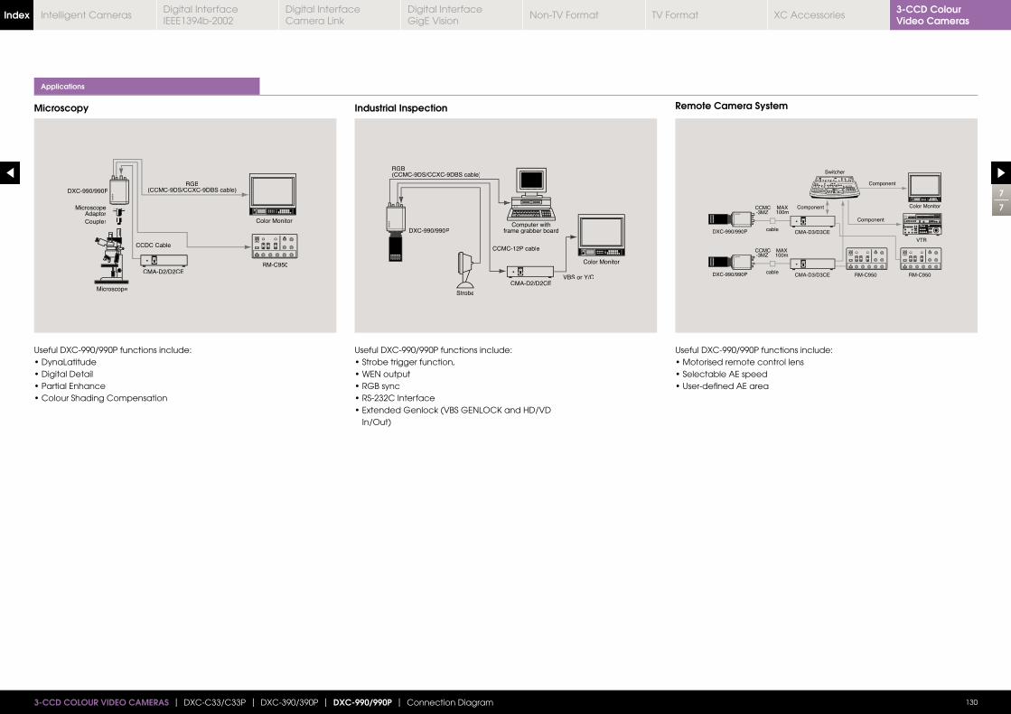
4
4
1303-CCD COLOUR VIDEO CAMERAS | DXC-C33/C33P | DXC-390/390P | DXC-990/990P | Connection Diagram
7
7
DXC-990/990P
MicroscopeAdaptorCoupler
Microscope
CCDC Cable
CMA-D2/D2CERM-C950
Color Monitor
RGB(CCMC-9DS/CCXC-9DBS cable)
CMA-D2/D2CE
Color Monitor
Strobe
VBS or Y/C
Computer withframe grabber boardDXC-990/990P
RGB(CCMC-9DS/CCXC-9DBS cable)
CCMC-12P cable
Applications
Microscopy Industrial Inspection Remote Camera System
Useful DXC-990/990P functions include: Useful DXC-990/990P functions include:
In/Out)
Useful DXC-990/990P functions include:
3-CCD Colour Video CamerasIndex Digital Interface
IEEE1394b-2002Digital Interface Camera Link
Digital InterfaceGigE Vision
Non-TV Format TV Format XC AccessoriesIntelligent Cameras
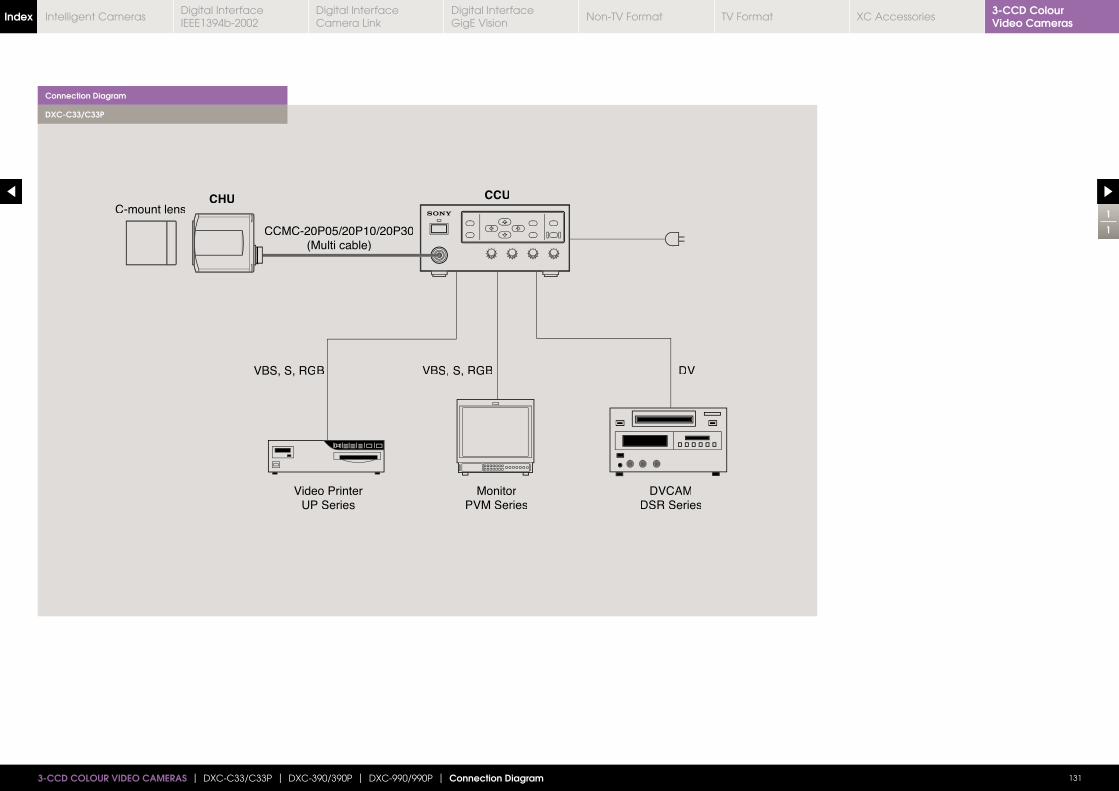
1
1
1313-CCD COLOUR VIDEO CAMERAS | DXC-C33/C33P | DXC-390/390P | DXC-990/990P | Connection Diagram
MonitorPVM Series
Video PrinterUP Series
VDBGR,S,SBVVBS, S, RGB
CCU
DVCAMDSR Series
CCMC-20P05/20P10/20P30(Multi cable)
CHUC-mount lens
Connection Diagram
DXC-C33/C33P
3-CCD Colour Video CamerasIndex Digital Interface
IEEE1394b-2002Digital Interface Camera Link
Digital InterfaceGigE Vision
Non-TV Format TV Format XC AccessoriesIntelligent Cameras
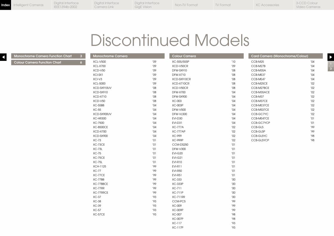
Monochrome Camera Function Chart 3
Colour Camera Function Chart 6
Monochrome Camera
XCL-V500 ‘09
XCL-X700 ‘09
XCD-V50 ‘09
XCI-SX1 ‘09
XCI-V3 ‘09
XCL-5000 ‘09
XCD-SX910UV ‘08
XCD-SX910 ‘08
XCD-X710 ‘08
XCD-V50 ‘08
XC-55BB ‘04
XC-55 ‘04
XCD-SX900UV ‘04
XC-HR300 ‘04
XC-7500 ‘04
XC-8500CE ‘04
XCD-X700 ‘04
XCD-SX900 ‘04
XC-73 ‘01
XC-73CE ‘01
XC-73L ‘01
XC-75 ‘01
XC-75CE ‘01
XC-75L ‘01
XCH-1125 ‘99
XC-77 ‘99
XC-77CE ‘99
XC-77BB ‘99
XC-77BBCE ‘99
XC-77RR ‘99
XC-77RRCE ‘99
XC-37 ‘93
XC-38 ‘93
XC-39 ‘93
XC-57 ‘93
XC-57CE ‘93
Colour Camera
XC-555/555P ‘10
XCD-V50CR ‘09
DFW-SX910 ‘08
DFW-X710 ‘08
XCD-SX910CR ‘08
XCD-X710CR ‘08
XCD-V50CR ‘08
DFW-X700 ‘04
DFW-SX900 ‘04
XC-003 ‘04
XC-003P ‘04
DFW-V500 ‘04
DFW-VL500 ‘04
EVI-D30 ‘04
EVI-D31 ‘04
XC-777A ‘02
XC-777AP ‘02
XC-999 ‘02
XC-999P ‘02
CCM-DS250 ‘01
DFW-V300 ‘01
EVI-G20 ‘01
EVI-G21 ‘01
EVI-R10 ‘01
EVI-R11 ‘01
EVI-R50 ‘01
EVI-R51 ‘01
XC-333 ‘00
XC-333P ‘00
XC-711 ‘00
XC-711P ‘00
XC-711RR ‘00
CCM-PC5 ‘99
XC-009 ‘99
XC-009P ‘99
XC-007 ‘98
XC-007P ‘98
XC-117 ‘93
XC-117P ‘93
Card Camera (Monochrome/Colour)
CCB-M25 ‘04
CCB-M27B ‘04
CCB-M35A ‘04
CCB-ME37 ‘04
CCB-ME47 ‘04
CCB-M25CE ‘02
CCB-M27BCE ‘02
CCB-M35ACE ‘02
CCB-M37 ‘02
CCB-M37CE ‘02
CCB-ME37CE ‘02
CCB-MS37CE ‘02
CCB-GC7YC ‘02
CCB-ME47CE ‘01
CCB-GC7YCP ‘01
CCB-GL5 ‘99
CCB-GL5P ‘99
CCB-GL5YC ‘98
CCB-GL5YCP ‘98
Discontinued Models1
3
Index Digital Interface IEEE1394b-2002
Digital Interface Camera Link
Digital InterfaceGigE Vision
Non-TV Format TV Format XC Accessories3-CCD Colour Video Cameras
Intelligent Cameras
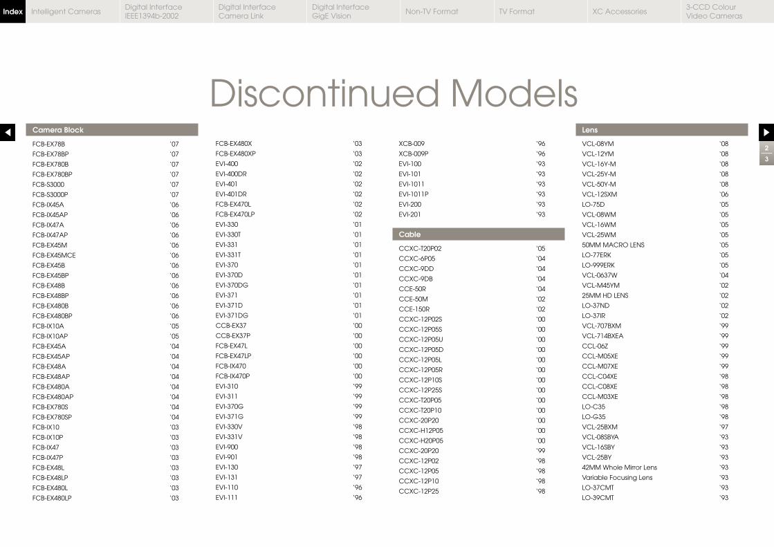
Camera Block
FCB-EX78B ‘07
FCB-EX78BP ‘07
FCB-EX780B ‘07
FCB-EX780BP ‘07
FCB-S3000 ‘07
FCB-S3000P ‘07
FCB-IX45A ‘06
FCB-IX45AP ‘06
FCB-IX47A ‘06
FCB-IX47AP ‘06
FCB-EX45M ‘06
FCB-EX45MCE ‘06
FCB-EX45B ‘06
FCB-EX45BP ‘06
FCB-EX48B ‘06
FCB-EX48BP ‘06
FCB-EX480B ‘06
FCB-EX480BP ‘06
FCB-IX10A ‘05
FCB-IX10AP ‘05
FCB-EX45A ‘04
FCB-EX45AP ‘04
FCB-EX48A ‘04
FCB-EX48AP ‘04
FCB-EX480A ‘04
FCB-EX480AP ‘04
FCB-EX780S ‘04
FCB-EX780SP ‘04
FCB-IX10 ‘03
FCB-IX10P ‘03
FCB-IX47 ‘03
FCB-IX47P ‘03
FCB-EX48L ‘03
FCB-EX48LP ‘03
FCB-EX480L ‘03
FCB-EX480LP ‘03
FCB-EX480X ‘03
FCB-EX480XP ‘03
EVI-400 ‘02
EVI-400DR ‘02
EVI-401 ‘02
EVI-401DR ‘02
FCB-EX470L ‘02
FCB-EX470LP ‘02
EVI-330 ‘01
EVI-330T ‘01
EVI-331 ‘01
EVI-331T ‘01
EVI-370 ‘01
EVI-370D ‘01
EVI-370DG ‘01
EVI-371 ‘01
EVI-371D ‘01
EVI-371DG ‘01
CCB-EX37 ‘00
CCB-EX37P ‘00
FCB-EX47L ‘00
FCB-EX47LP ‘00
FCB-IX470 ‘00
FCB-IX470P ‘00
EVI-310 ‘99
EVI-311 ‘99
EVI-370G ‘99
EVI-371G ‘99
EVI-330V ‘98
EVI-331V ‘98
EVI-900 ‘98
EVI-901 ‘98
EVI-130 ‘97
EVI-131 ‘97
EVI-110 ‘96
EVI-111 ‘96
XCB-009 ‘96
XCB-009P ‘96
EVI-100 ‘93
EVI-101 ‘93
EVI-1011 ‘93
EVI-1011P ‘93
EVI-200 ‘93
EVI-201 ‘93
Cable
CCXC-T20P02 ‘05
CCXC-6P05 ‘04
CCXC-9DD ‘04
CCXC-9DB ‘04
CCE-50R ‘04
CCE-50M ‘02
CCE-150R ‘02
CCXC-12P02S ‘00
CCXC-12P05S ‘00
CCXC-12P05U ‘00
CCXC-12P05D ‘00
CCXC-12P05L ‘00
CCXC-12P05R ‘00
CCXC-12P10S ‘00
CCXC-12P25S ‘00
CCXC-T20P05 ‘00
CCXC-T20P10 ‘00
CCXC-20P20 ‘00
CCXC-H12P05 ‘00
CCXC-H20P05 ‘00
CCXC-20P20 ‘99
CCXC-12P02 ‘98
CCXC-12P05 ‘98
CCXC-12P10 ‘98
CCXC-12P25 ‘98
Lens
VCL-08YM ‘08
VCL-12YM ‘08
VCL-16Y-M ‘08
VCL-25Y-M ‘08
VCL-50Y-M ‘08
VCL-12SXM ‘06
LO-75D ‘05
VCL-08WM ‘05
VCL-16WM ‘05
VCL-25WM ‘05
50MM MACRO LENS ‘05
VCL-0637W ‘04
VCL-M45YM ‘02
25MM HD LENS ‘02
LO-37ND ‘02
LO-37IR ‘02
VCL-707BXM ‘99
VCL-714BXEA ‘99
CCL-06Z ‘99
CCL-M05XE ‘99
CCL-M07XE ‘99
CCL-C04XE ‘98
CCL-C08XE ‘98
CCL-M03XE ‘98
LO-C35 ‘98
LO-G35 ‘98
VCL-25BXM ‘97
VCL-08SBYA ‘93
VCL-16SBY ‘93
VCL-25BY ‘93
42MM Whole Mirror Lens ‘93
Variable Focusing Lens ‘93
LO-37CMT ‘93
LO-39CMT ‘93
Discontinued Models2
3
Index Digital Interface IEEE1394b-2002
Digital Interface Camera Link
Digital InterfaceGigE Vision
Non-TV Format TV Format XC Accessories3-CCD Colour Video Cameras
Intelligent Cameras
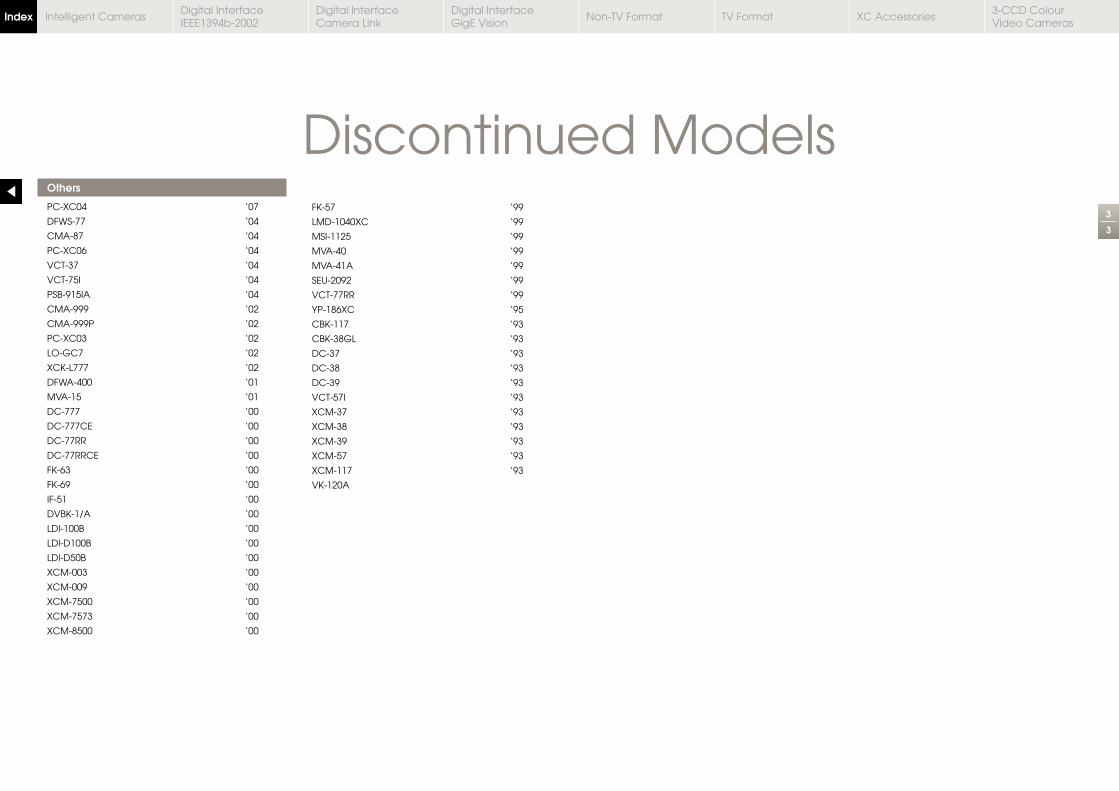
Others
PC-XC04 ‘07
DFWS-77 ‘04
CMA-87 ‘04
PC-XC06 ‘04
VCT-37 ‘04
VCT-75I ‘04
PSB-915IA ‘04
CMA-999 ‘02
CMA-999P ‘02
PC-XC03 ‘02
LO-GC7 ‘02
DFWA-400 ‘01
MVA-15 ‘01
DC-777 ‘00
DC-777CE ‘00
DC-77RR ‘00
DC-77RRCE ‘00
IF-51 ‘00
LDI-100B ‘00
LDI-D100B ‘00
LDI-D50B ‘00
XCM-003 ‘00
XCM-009 ‘00
XCM-7500 ‘00
XCM-7573 ‘00
XCM-8500 ‘00
LMD-1040XC ‘99
MSI-1125 ‘99
MVA-40 ‘99
MVA-41A ‘99
SEU-2092 ‘99
VCT-77RR ‘99
YP-186XC ‘95
DC-37 ‘93
DC-38 ‘93
DC-39 ‘93
VCT-57I ‘93
XCM-37 ‘93
XCM-38 ‘93
XCM-39 ‘93
XCM-57 ‘93
XCM-117 ‘93
Discontinued Models3
3
Index Digital Interface IEEE1394b-2002
Digital Interface Camera Link
Digital InterfaceGigE Vision
Non-TV Format TV Format XC Accessories3-CCD Colour Video Cameras
Intelligent Cameras