monitoring and management of subsidence induced by ... · monitoring and management of subsidence...
TRANSCRIPT

Monitoring and management of subsidence induced by longwall coal mining activity
This report was commissioned by the Department of the Environment on the
advice of the Independent Expert Scientific Committee on Coal Seam Gas and
Large Coal Mining Development. The review was prepared by Jacobs Group
(Australia) with input from Mine Engineering Subsidence Consultants and Strata
Control Technology.
August 2015

Monitoring and management of subsidence induced by longwall coal mining activity
page ii
Copyright
© Copyright Commonwealth of Australia, 2015.
Monitoring and management of subsidence induced by longwall coal mining activity is licensed by the Commonwealth of Australia for use under a Creative Commons By Attribution 3.0 Australia licence with the exception of the Coat of Arms of the Commonwealth of Australia, the logo of the agency responsible for publishing the report, content supplied by third parties, and any images depicting people. For licence conditions see: http://creativecommons.org/licenses/by/3.0/au/
This report should be attributed as ‘Commonwealth of Australia 2015, Management and monitoring of subsidence induced by longwall coal mining activity, prepared by Jacobs Group (Australia) for the Department of the Environment, Commonwealth of Australia, Canberra’.
The Commonwealth of Australia has made all reasonable efforts to identify content supplied by third parties using the following format ‘© Copyright, [name of third party] ’.
Enquiries concerning reproduction and rights should be addressed to:
Department of the Environment, Public Affairs GPO Box 787 Canberra ACT 2601
Or by email to: [email protected]
This publication can be accessed at: www.iesc.environment.gov.au
Acknowledgements
This report was commissioned by the Department of the Environment on the advice of the Independent Expert Scientific Committee on Coal Seam Gas and Large Coal Mining Development (IESC). The report was prepared by Jacobs Group (Australia) with input from Mine Subsidence Engineering Consultants (MSEC) and Strata Control Technology.
The report was peer reviewed by Professor Derek Ellsworth (Chair of Departments of Energy and Mineral Engineering and of Geosciences and the Center for Geomechanics, Geofluids, and Geohazards, Pennsylvania State University) and Ms Karina Barbosa (Research Engineer, School of Earth Sciences, University of Queensland). Consultation with various Queensland and New South Wales Government agencies (the only Australian states with longwall mines) was undertaken via a project workshop (November 2014) and the opportunity to provide comments on the draft report.
Disclaimer
The views and opinions expressed in this publication are those of the authors and do not necessarily reflect those of the Australian Government or the Minister for the Environment or the IESC.
While reasonable efforts have been made to ensure that the contents of this publication are factually correct, the Commonwealth and IESC do not accept responsibility for the accuracy or completeness of the contents, and shall not be liable for any loss or damage that may be occasioned directly or indirectly through the use of, or reliance on, the contents of this publication.

Monitoring and management of subsidence induced by longwall coal mining activity
page iii
Contents
Summary ............................................................................................................................................... viii
Abbreviations .......................................................................................................................................... xii
Glossary.................................................................................................................................................. xv
1 Introduction ......................................................................................................................................... 1
1.1 Outline ........................................................................................................................................ 1
1.2 Background ................................................................................................................................ 1
2 Review of subsidence impacts on groundwater and surface water resources .................................. 3
2.1 Longwall coal mining method ..................................................................................................... 3
2.2 Longwall coal mining subsidence............................................................................................. 10
2.3 Impact of longwall coal mine subsidence on groundwater ...................................................... 24
2.4 Impact of longwall coal mining on surface water resources .................................................... 32
2.5 Subsidence mitigation and remediation methods .................................................................... 43
3 Evaluation of modelling tools ............................................................................................................ 52
3.1 Subsidence modelling methods ............................................................................................... 52
3.2 Groundwater modelling methods ............................................................................................. 85
3.3 Surface water modelling methods ............................................................................................ 97
4 Evaluation of monitoring and measurement approaches ............................................................... 113
4.1 Monitoring subsidence ........................................................................................................... 113
4.2 Groundwater monitoring ......................................................................................................... 127
4.3 Surface water monitoring ....................................................................................................... 132
5 Generic approach for investigating subsidence related impacts on groundwater and surface water resources ........................................................................................................................................ 138
5.1 Step 1: Identify water resource assets ................................................................................... 140
5.2 Step 2: Characterise the assets and determine management objectives ............................. 141
5.3 Step 3: Qualitative risk assessment ....................................................................................... 142
5.4 Step 4: Baseline monitoring ................................................................................................... 144
5.5 Step 5: Conceptual model development ................................................................................ 146
5.6 Step 6: Quantitative estimate of subsidence .......................................................................... 150
5.7 Step 7a: Quantitative estimate of the impact of subsidence on groundwater resources ....... 150
5.8 Step 7b: Quantitative estimate of the impact of subsidence on surface water resources ..... 151
5.9 Step 4, 5, 6 and 7 iterations ................................................................................................... 152
5.10 Step 8: Quantitative risk assessment ................................................................................... 152
5.11 Step 9: Assessment of mitigation measures ........................................................................ 153
5.12 Step 10: Post-mining monitoring .......................................................................................... 153
5.13 Step 11: Validation of predictions ........................................................................................ 154
5.14 How the generic approach fits Queensland environmental regulation ................................ 155
6 Description of coal deposits in Queensland amenable to longwall coal mining ............................. 158

Monitoring and management of subsidence induced by longwall coal mining activity
page iv
6.1 Introduction to coal deposits in Queensland .......................................................................... 158
6.2 Description of the Bowen Basin ............................................................................................. 165
6.3 Description of the Galilee Basin ............................................................................................. 183
6.4 Differences between NSW and Queensland coal deposits ................................................... 207
6.5 Summary of conceptual models ............................................................................................. 214
7 Knowledge gaps and limitations ..................................................................................................... 218
7.1 Subsidence mechanisms ....................................................................................................... 218
7.2 Impacts on groundwater ......................................................................................................... 219
7.3 Impacts on surface water and connected groundwater ......................................................... 220
7.4 Predictive methods ................................................................................................................. 220
7.5 Understanding of Queensland coal basins ............................................................................ 221
7.6 Subsidence management ...................................................................................................... 222
8 Findings and implications ............................................................................................................... 223
8.1 Subsidence prediction methods ............................................................................................. 223
8.2 Subsidence mechanisms and impact on groundwater and surface water resources............ 224
8.3 Monitoring and measurement methods ................................................................................. 224
8.4 Generic approach for assessing the impacts of longwall coal mine subsidence ................... 225
8.5 Conceptual models of Queensland coal deposits amenable to longwall coal mining ........... 225
8.6 Management and mitigation of longwall coal mine subsidence ............................................. 226
9 References ..................................................................................................................................... 228
Appendix A: MSEC report on the accuracy of the Incremental Profile Method .................................. 244
Appendix B: Surface water assets in coal basins ............................................................................... 245
Tables
Table 3.1 Subsidence simulation and prediction methods described in this report .............................. 52
Table 3.2 Summary of RMS and SRMS errors for analysis of IPM predictions of maximum subsidence .................................................................................................................................. 67
Table 3.3 Summary of subsidence modelling methods ........................................................................ 82
Table 3.4 Catchment hydrology models for surface waters impacted by subsidence .......................... 99
Table 3.5 Stream/river hydraulic models for surface waters impacted by subsidence ......................... 99
Table 3.6 Rainfall/runoff catchment hydrology model data requirements ........................................... 100
Table 3.7 Stream/river hydraulic model data requirements ................................................................ 100
Table 3.8 Water quality models for surface waters impacted by subsidence ..................................... 101
Table 3.9 Surface and groundwater interaction models for surface waters impacted by subsidence ................................................................................................................................ 102
Table 3.10 Stream and landscape geomorphology models for surface waters impacted by subsidence ................................................................................................................................ 102
Table 4.1 Summary of InSAR-based methods .................................................................................... 121
Table 4.2 Summary table of past, operational and future satellite radar missions (not exhaustive) ................................................................................................................................ 122
Table 4.3 Summary of remote sensing methods for subsidence monitoring ...................................... 124
Table 6.1 Longwall coal mines in Queensland .................................................................................... 163
Monitoring and management of subsidence induced by longwall coal mining activity
page v
Table 6.2 Generalised stratigraphy for the Bowen Basin .................................................................... 165
Table 6.3 Generalised hydrostratigraphy of the Bowen Basin including aquifer quality, yield and management ...................................................................................................................... 168
Table 6.4 Coal seam geotechnical parameters for subsidence prediction at the Ellensfield Coal Mine, northern Bowen Basin ............................................................................................ 172
Table 6.5 Overburden geotechnical parameters for subsidence prediction at the Ellensfield Coal Mine, northern Bowen Basin ............................................................................................ 173
Table 6.6 Information used to characterise surface water resources ................................................. 174
Table 6.7 Estimated number of GDEs in the Bowen Basin ................................................................. 178
Table 6.8 Thickness of stratigraphic units at various coal mine sites collated from EIS information ................................................................................................................................ 186
Table 6.9 Generalised hydrostratigraphy of the Galilee Basin including aquifer quality, yield and management ...................................................................................................................... 191
Table 6.10 Coal seam geotechnical input parameters for subsidence prediction at the Alpha Coal Mine, Galilee Basin .......................................................................................................... 200
Table 6.11 Overburden geotechnical input parameters used for subsidence prediction at the Alpha Coal Mine, Galilee Basin .......................................................................................... 200
Table 6.12 Galilee Basin estimated number of GDEs (reliant on the surface expression of groundwater) by coal basin ....................................................................................................... 202
Table 6.13 Summary of differences in geotechnical, groundwater and surface water characteristics of the Queensland coal basins amenable to coal mining relative to the Sydney Basin in NSW ............................................................................................................... 215
Figures
Figure 2.1 Australian coal resources ....................................................................................................... 4
Figure 2.2 An operating longwall coal mine face..................................................................................... 5
Figure 2.3 Schematic cutaway view of a typical longwall coal mine ....................................................... 6
Figure 2.4 Plan layout of a typical longwall mine, also showing some bord and pillar workings ........................................................................................................................................ 7
Figure 2.5 Typical shearer, conveyor and hydraulic support chocks ...................................................... 8
Figure 2.6 A line of hydraulic longwall face supports, each about 1.75 m wide, which can each move forward sequentially in a snaking motion ................................................................... 8
Figure 2.7 Cross-section of a typical longwall showing the fracturing occurring as the overlying strata collapse into the goaf .......................................................................................... 9
Figure 2.8 Redistribution of forces around a narrow excavation ........................................................... 11
Figure 2.9 Physical model of subsided longwall panel being extracted from left to right ...................... 11
Figure 2.10 Caving, fracturing and subsidence above a longwall panel ............................................... 12
Figure 2.11 Development of subsidence parameters in relation to the mining void geometry ............. 13
Figure 2.12 Development of a subsidence trough (to an exaggerated vertical scale; noting that subsidence in reality does not exceed the height of the working face) ............................... 18
Figure 2.13 Conceptual model for piezometric response of a fractured rock aquifer above a longwall fractured zone ............................................................................................................... 26
Figure 2.14 Comparison of modelled and measured conductivity data with empirical data relating strain and inflow ............................................................................................................. 27
Figure 2.15 Conceptual timeline showing time lags between first, second and third order impacts ........................................................................................................................................ 32
Figure 2.16 Distance of observed fractures to closest edge of longwall ............................................... 33
Monitoring and management of subsidence induced by longwall coal mining activity
page vi
Figure 2.17 Representation of surface water diversion into subterranean flow and rock bar leakage, and how rates of flows are potentially affected by subsidence induced fracturing ..................................................................................................................................... 35
Figure 2.18 Effect of subsidence induced surface flow diversion showing loss of stream flow during low flow events ......................................................................................................... 36
Figure 2.19 Geomorphic response to sediment extraction ................................................................... 40
Figure 3.1 An output of the surface deformation prediction system (SDPS) showing a shaded relief surface of subsided topography ............................................................................ 59
Figure 3.2 Example of an incremental subsidence profile during the mining of any one longwall panel; the total subsidence on completion of mining any one panel; and the total subsidence at the end of mining a series of panels ............................................................ 62
Figure 3.3 Comparison of predicted versus observed valley closures using the ACARP method ........................................................................................................................................ 70
Figure 3.4 A comparison of predicted and observed valley upsidence using the ACARP method ........................................................................................................................................ 74
Figure 3.5 Average overburden conductivity characteristics relative to subsidence and depth criteria ............................................................................................................................... 78
Figure 3.6 Numerical modelling process ............................................................................................... 98
Figure 3.7 Quality assured surface water modelling process ............................................................. 104
Figure 3.8 Ensham Central Project location and layout ...................................................................... 109
Figure 3.9 Location of the Bulli Seam Operations and nearby surface waters ................................... 111
Figure 3.10 Water balance model schematic for a rock bar pool ........................................................ 111
Figure 3.11 Modelled flow exceedance curves for a pool showing the effect of subsidence ............. 112
Figure 4.1 Results of subsidence monitoring from a single line of pegs at Westcliff Colliery (labelled as B084 to B234) during extraction of a longwall panel ............................................. 115
Figure 4.2 Measurements made in a control traverse ......................................................................... 116
Figure 4.3 A pair of GPS survey receivers recording carrier phase measurements used to derive an accurate baseline between receivers ....................................................................... 117
Figure 4.4 A real time kinematic GNSS survey ................................................................................... 118
Figure 4.5 Three underground coal mines in close proximity: Tower (blue; left), Appin (red; centre) and West Cliff (orange; right) which can be monitored in a single satellite scene under a single analysis, compared to the single ground transects (yellow lines) which are more field intensive and costly to survey ........................................................ 119
Figure 4.6 DInSAR mine subsidence map in southwest NSW ............................................................ 122
Figure 4.7 Simple set up of an extensometer measuring subsurface subsidence.............................. 126
Figure 4.8 Example of a piezometer used to monitor groundwater levels and quality (Jacobs file diagram) ................................................................................................................. 129
Figure 4.9 Example of groundwater chemistry results plotted on a Piper diagram for the proposed Carmichael Coal Mine in the Galilee Basin in Queensland ...................................... 131
Figure 4.10 Possible pathway for surface water impacts of subsidence ............................................ 133
Figure 5.1 Flow chart for investigating the impacts of longwall coal mine subsidence on groundwater and surface water resources ............................................................................... 139
Figure 5.2 Example of a risk rating table for combining likelihood and consequence ratings ............ 143
Figure 5.3 Simple conceptual model of Lockyer Creek and catchment .............................................. 148
Figure 5.4 Possible scheduling of proposed generic approach for investigating longwall coal mine subsidence within the Queensland environmental regulatory process............................ 157
Figure 6.1 Location of coal deposits and coal mines in the Central Queensland region .................... 159
Figure 6.2 Location of coal deposits and coal mines in the Western Central Queensland region ........................................................................................................................................ 160

Monitoring and management of subsidence induced by longwall coal mining activity
page vii
Figure 6.3 Location of coal deposits and coal mines in the south-eastern Queensland region ........................................................................................................................................ 161
Figure 6.4 Location of longwall coal mines in the Bowen and Galilee Basins .................................... 162
Figure 6.5 Regional correlation sections through Supermodel 2000 tiles showing general thickness and splitting patterns of the major superseams over a section length of 200 km from 75 km north of Moranbah to 25 km north of Emerald, Qld ......................................... 167
Figure 6.6 Significant wetlands and GDEs in the northern Bowen Basin ........................................... 176
Figure 6.7 Significant wetlands and GDEs in the southern Bowen Basin ........................................... 177
Figure 6.8 Schematic depiction of wetland systems present in Queensland ...................................... 179
Figure 6.9 Conceptual model diagram for the Bowen Basin illustrating some of the concepts described in Sections 6.2.1 to 6.2.5 .......................................................................... 182
Figure 6.10 The Galilee Basin and its subdivisions, provenances/basement, contemporaneous basins and underlying basins ..................................................................... 184
Figure 6.11 Simplified hydrostratigraphy of the Galilee and Eromanga Basins .................................. 185
Figure 6.12 Northwest to southeast stratigraphic cross-section of the Galilee Basin ......................... 187
Figure 6.13 Southwest to northeast stratigraphic cross-section of the Galilee Basin ......................... 188
Figure 6.14 Significant wetlands and GDEs in the Galilee Basin........................................................ 203
Figure 6.15 Conceptual model diagram for the Galilee Basin illustrating some of the concepts described in Sections 6.3.1 to 6.3.5 .......................................................................... 206
Figure 6.16 Stratigraphic framework for the major coal regions of the Sydney Basin ........................ 209

Monitoring and management of subsidence induced by longwall coal mining activity
page viii
Summary
This report describes modelling tools and approaches for predicting, monitoring and measuring subsidence due to longwall coal mining and its impacts on groundwater and surface water resources. Based on a long history of longwall coal mining in New South Wales, a generic approach is presented for investigating subsidence related impacts on groundwater and surface water resources that can be applied in Queensland where longwall coal mining is at an earlier stage.
Longwall coal mining is the most common underground coal extraction method in Australia because of its relatively low cost, strong safety record and efficiency in removing coal from deep seams.
The longwall method extracts large rectangular panels of coal at depth. The coal is progressively mined by a shearer that shaves off slices of coal up to 1 m thick from the longwall face, under the protection of hydraulic supports, until the panel is fully extracted. As the shearer progresses forward, the roof and overlying rock collapse into the void behind. Eventually the mined-out void becomes too wide to be self-supporting, causing the roof of the void to sag, which starts a process that results in caving that extends both horizontally and vertically beyond the footprint of the mine excavation. Subsidence in the ‘caving zone’ in and around the void created by mining propagates upwards into the ‘fracture zone’ and, finally, to the surface.
Longwall coal mining subsidence can affect groundwater resources in the collapse and fracture zone immediately above the mined coal seam and the overlying strata. The process causes changes in permeability, porosity and groundwater levels. In the collapse and fracture zones, the aquifer permeability increases with a corresponding drop in groundwater levels. Above the fracture zone the typical groundwater response to changes in physical rock properties is a gradual lowering of groundwater levels ahead of the face, leading to a fairly rapid and large drop in head as the face passes beneath the point of interest, followed by a gradual recovery over time (either to pre-mining levels or below).
Subsidence caused by longwall mining techniques has been found to have impacts on surface water assets including rivers and wetlands and associated ecosystems. Much of the information on the type of impact comes from New South Wales (NSW) examples especially in the peat swamp areas of the Sydney Basin. The magnitude of change in surface and subsurface flow is dependent on the extent to which subsidence changes the structure of the overlying strata. The level of impact is dependent on the degree of subsidence, the substrate, slope, and geomorphology of the surface water environment. The types and ranges of impacts can be divided into impacts on topography, geomorphology, hydrology and ecology.
The damaging effects of subsidence are primarily mitigated by modifying mine layouts to protect specific surface structures and water resource assets. The usual aim is to minimise the more critical subsidence parameters (i.e. tensile strains and tilt) rather than to reduce vertical movement. Where protection of surface waters and aquifers is the primary concern, the aim is to limit vertical crack propagation. Subsidence is primarily minimised by retaining sections of coal to support the overlying strata. This is now supplemented by much more intensive geological investigations, rock mechanical testing and numerical modelling of alternative mine layouts and dimensions. Other methods to reduce the impact of subsidence

Monitoring and management of subsidence induced by longwall coal mining activity
page ix
have not been generally implemented in Australia but include backfilling or ‘stowing’ of the mined out void, and bed separation grouting.
Subsidence prediction methods can be classified into the following groups:
Empirical methods: patterns of rock and soil behaviour are developed from field
measurements, which are used to predict the impacts of various mining scenarios in
similar geotechnical environments.
Numerical modelling methods: numerical simulation using known equations of rock,
water and soil behaviour.
Empirical methods are commonly used in Australia for predicting surface subsidence. These include the Incremental Profile Method (IPM) developed by consulting company Mine Subsidence Engineering Consultants (MSEC) which has developed an application of the IPM using a database developed since 1996 using more than 800 000 subsidence measurements from over 50 collieries in NSW and four collieries in Queensland. The application of the IPM by MSEC is designed to be conservative with predictions being skewed towards an over-estimate of maximum subsidence to reduce the chance that predicted subsidence values will be exceeded. The accuracy of prediction is greatly improved by calibrating the results of the IPM to local subsidence data.
Numerical modelling methods are favoured over empirical techniques in the cases where the geotechnical conditions are substantially different from those used to develop the empirical techniques; and information on changes to groundwater resources in the caving or fracture zone is required.
Techniques for monitoring subsurface subsidence and subsidence impacts have historically been confined to traditional ground survey techniques. While satellite radar imaging has been shown to provide the level of accuracy required for meaningful analysis of surface subsidence impacts, it has yet to gain widespread acceptance for single mine situations due to its cost (although it is reasonably cost-effective when used over multiple mine sites at the same time).As new satellites and new processing techniques become available, satellite radar technology is likely to become more cost-effective and popular for monitoring mine subsidence.
A generic approach is outlined for investigating longwall coal mine subsidence. This provides a suggested approach to proponents and regulators on the appropriate components and sequence of investigation, spanning the life of a mine (from exploration through to pre-feasibility, feasibility, production and rehabilitation, closure, and post-mining management stages).The approach uses a broad risk assessment to first identify and document the value of assets at possible risk from mine subsidence, then uses predictive techniques to identify the likelihood of impact and monitoring results to validate the assessment and refine the risk assessment.
The approach tailors the effort depending on the type and value of the environmental assets at possible risk. Complex and expensive modelling exercises can be avoided if there are no high value water resource assets within the potential area of influence of the mine, or if the assets have a very low risk of being affected. Following the procedure will help the complexity, time, and expense of the investigation to remain commensurate with the economic, social, and environmental value of the assets and level of potential risk, although the method needs to be applied, tested and refined before wholesale adoption.

Monitoring and management of subsidence induced by longwall coal mining activity
page x
In Queensland, longwall mining methods are currently used in the Bowen Basin and are planned in the Galilee Basin. There is a general paucity of data and experience on the behaviour and impact of longwall coal mine subsidence in Queensland (particularly in the Galilee Basin). There is a need for caution when applying empirical methods primarily derived from NSW examples to the Galilee and Bowen Basins in Queensland. In the Bowen Basin, the area of planned and historic longwall coal mining has the potential to impact the Tertiary basalt and Quaternary alluvial aquifers, both of which already support existing water users. In most cases, there are significant thicknesses of the low permeability Rewan Formation that may hydraulically separate the coal measures from overlying units. The effectiveness of this seal has not been field-validated and structural features may enhance preferential flow paths through the Rewan Formation aquitard. Given that all of the longwall mining developments in the Bowen Basin (historic, current and planned) are well outside the Great Artesian Basin (GAB) boundary, the likelihood of impact of longwall coal mine subsidence on GAB units (including the Clematis Sandstone Aquifer) may be considered low. However, there are isolated outcrops of Clematis Sandstone outside the GAB which could potentially be impacted by longwall coal mining, such as in and around the Karborough Range and Kerlong Range north of Coppabella (e.g. near the Ellensfield Mine).
Areas for further research in understanding and predicting subsidence include:
methods to predict horizontal movements (often the cause of significant damage to
surface infrastructure)
understanding the reason for the sudden change in subsidence behaviour when the
‘critical width’ of extraction is exceeded, and the lack of methods available to predict this
width
methods to predict near surface anomalous movements (generally small and very
localised but can be damaging to surface structures)
understanding mechanisms and prediction methods for far field movements (largely
horizontal) away from the main area of surface subsidence
methods for predicting subsidence for multi-seam mining
predicting subsidence in three dimensions (currently modelling outputs are usually
confined to two-dimensional cross sections, mainly due to the limitation of computing
power and modelling software packages).
Areas for further research on the impacts of subsidence on groundwater and surface water resources include:
the capacity of streams affected by bedrock cracking to ‘self-heal’ and possible actions
to accelerate this process
the chemical processes occurring when groundwater and surface waters mix in
situations of bedrock cracking
the behaviour of groundwater in the caved and fractured zones display many departures
from theoretical conceptual models
the effectiveness of engineering methods to reduce subsidence, including backfilling or
‘stowing’, and bed separation grouting

Monitoring and management of subsidence induced by longwall coal mining activity
page xi
the hydraulic behaviour of shales and mudstones under subsidence conditions and their
capacity to behave in either a brittle (crack generating) or plastic (self sealing, like putty)
manner, which can dramatically change the impact on overlying aquifers.

Monitoring and management of subsidence induced by longwall coal mining activity
page xii
Abbreviations
General abbreviations
Description
ACARP Australian Coal Association Research Program
ALS Airborne Laser Scanning
ANU Australian National University
ANZECC Australian and New Zealand Environment and Conservation Council
AoD Angle of Draw
ARI Average Recurrence Interval
ARMCANZ Agriculture and Resource Management Council of Australia and New Zealand
BACI Before-After Control Impact
BM Bench Mark
CSG Coal seam gas
CSIRO Commonwealth Scientific and Industrial Research Organisation
COAG Council of Australian Governments
COI Commissioners of Inquiry
DEH NSW Department of Environment and Heritage
DERM Queensland Department of Environment and Resource Management
DEM Digital Elevation Model
DEW Federal Department of Environment and Water
DEWHA Federal Department of Environment, Water, Heritage and the Arts
DHI Danish Hydraulics Institute
DInSAR Differential Interferometric Synthetic Aperture Radar
DIPNR NSW Department of Infrastructure Planning and Natural Resources
DIWA Directory of Important Wetlands in Australia
DMR or NSW DMR NSW Department of Mineral Resources
NSW DoP NSW Department of Planning
DSEWPaC Federal Department of Sustainability, Environment, Water, Populations and Communities
DTI NSW Department of Trade and Investment
EC Electrical conductivity
Eh Reduction potential (also known as redox potential, oxidation/reduction potential,

Monitoring and management of subsidence induced by longwall coal mining activity
page xiii
General abbreviations
Description
ORP, pE or ɛ)
EIS Environmental Impact Statement
EPBC Environment Protection and Biodiversity Conservation Act 1999 (Cwlth)
FEFLOW Finite Element Sub-surface Flow and Transport Simulation System
Fm Formation
GAB Great Artesian Basin
GDEs Groundwater dependent ecosystems
GIS Geographic Information System
GMAs Groundwater management areas
GMU Groundwater management units
GNSS Global Navigation Satellite System
GPS Global Positioning Systems
GSQ Geological Survey of Queensland
GUI Graphical User Interface
IAR Impact Assessment Report
ICSM Inter-governmental Committee on Surveying and Mapping
IESC Independent Expert Scientific Committee on Coal Seam Gas and Large Coal Mining Development
InSAR Interferometric Synthetic Aperture Radar
IPM Incremental Profile Method
ITS Indirect Tensile Strength
LiDAR Light Detection and Ranging
MBACI Multiple Before-After Control Impact
MSB Mine Subsidence Board
MSEC Mine Subsidence Engineering Consultants
NCB National Coal Board
NCGRT National Centre for Groundwater Research and Training
NSW New South Wales
NSW PAC NSW Planning Assessment Commission
NSW SC NSW Scientific Committee
NWC National Water Commission

Monitoring and management of subsidence induced by longwall coal mining activity
page xiv
General abbreviations
Description
OSMRE Office of Surface Mining, Reclamation and Enforcement
OWS Office of Water Science, Department of the Environment
PSInSAR Persistent Scatterers Synthetic Aperture Radar Interferometry
PSMs Permanent Survey Marks
QDEEDI Queensland Department of Employment, Economic Development and Innovation
QDNRM Queensland Department of Natural Resources and Mines
QEHP Queensland Department of Environment and Heritage Protection
Qld Queensland
QWC Queensland Water Commission
RMS or RMSE Root Mean Square or Root Mean Squared Error
SAR Synthetic Aperture Radar
SCA Sydney Catchment Authority
SCT Strata Control Technology
SDPS Surface Deformation Prediction System
SKM Sinclair Knight Merz Pty Ltd
SMP Subsidence Management Plan
SRMS Scaled Root Mean Square
SWC Sydney Water Corporation
TDS Total Dissolved Solids
UK United Kingdom
UCS Unconfined Compressive Strength
UDEC Universal Distinct Element Code
US EPA US Environmental Protection Agency
US or USA United States of America
USGS US Geological Survey
Monitoring and management of subsidence induced by longwall coal mining activity
page xv
Glossary
Term Description
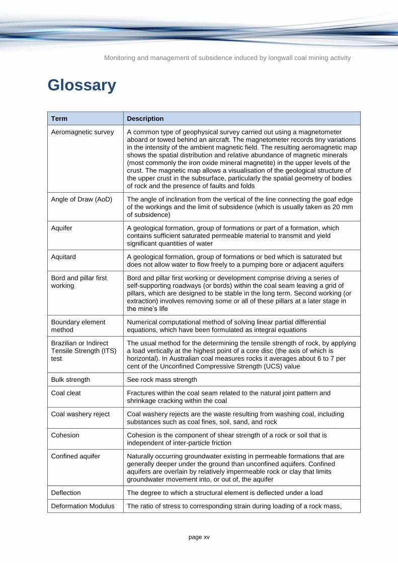
Aeromagnetic survey A common type of geophysical survey carried out using a magnetometer aboard or towed behind an aircraft. The magnetometer records tiny variations in the intensity of the ambient magnetic field. The resulting aeromagnetic map shows the spatial distribution and relative abundance of magnetic minerals (most commonly the iron oxide mineral magnetite) in the upper levels of the crust. The magnetic map allows a visualisation of the geological structure of the upper crust in the subsurface, particularly the spatial geometry of bodies of rock and the presence of faults and folds
Angle of Draw (AoD) The angle of inclination from the vertical of the line connecting the goaf edge of the workings and the limit of subsidence (which is usually taken as 20 mm of subsidence)
Aquifer A geological formation, group of formations or part of a formation, which contains sufficient saturated permeable material to transmit and yield significant quantities of water
Aquitard A geological formation, group of formations or bed which is saturated but does not allow water to flow freely to a pumping bore or adjacent aquifers
Bord and pillar first working
Bord and pillar first working or development comprise driving a series of self-supporting roadways (or bords) within the coal seam leaving a grid of pillars, which are designed to be stable in the long term. Second working (or extraction) involves removing some or all of these pillars at a later stage in the mine’s life
Boundary element method
Numerical computational method of solving linear partial differential equations, which have been formulated as integral equations
Brazilian or Indirect Tensile Strength (ITS) test
The usual method for the determining the tensile strength of rock, by applying a load vertically at the highest point of a core disc (the axis of which is horizontal). In Australian coal measures rocks it averages about 6 to 7 per cent of the Unconfined Compressive Strength (UCS) value
Bulk strength See rock mass strength
Coal cleat Fractures within the coal seam related to the natural joint pattern and shrinkage cracking within the coal
Coal washery reject Coal washery rejects are the waste resulting from washing coal, including substances such as coal fines, soil, sand, and rock
Cohesion Cohesion is the component of shear strength of a rock or soil that is independent of inter-particle friction
Confined aquifer Naturally occurring groundwater existing in permeable formations that are generally deeper under the ground than unconfined aquifers. Confined aquifers are overlain by relatively impermeable rock or clay that limits groundwater movement into, or out of, the aquifer
Deflection The degree to which a structural element is deflected under a load
Deformation Modulus The ratio of stress to corresponding strain during loading of a rock mass,

Monitoring and management of subsidence induced by longwall coal mining activity
page xvi
Term Description
including elastic and inelastic behaviour. This is a parameter that cannot be measured, but which is estimated by scaling downwards from values of Young’s Modulus derived from Unconfined Compressive Strength (UCS) testing of drill core samples
Dip The angle below the horizontal plane of an inclined bedding plane, measured perpendicular to the direction of strike
Discontinuity A rock mechanics term for all those weakening elements (joints, bedding, fractures, faults, etc.) that convert unbroken intact rock into a rock mass. The distinction between intact (testable) rock and rock masses is important in numerical modelling of subsidence
Distinct element method
Family of numerical methods for computing the motion and effect of a large number of small particles. Also known as the discrete element method
Downflexure The concave bending of strata
Dyke A near-vertical planar igneous rock intrusion, typically 1 to 10 m wide. Its effect on a subsidence profile is similar to that of a fault
Facies The appearance and characteristics of a sedimentary deposit, especially as they reflect the conditions and environment of deposition and serve to distinguish the deposit from contiguous deposits
Fault A geological planar discontinuity which causes rock strata and coal seams to be displaced (offset vertically or horizontally) on either side of the fault plane. It differs from a joint in being more penetrative within the overburden rock mass and in having less shearing resistance. It may cause stepping or concentration of ground strains at one point in a subsidence profile
Finite Difference Method
The finite difference method is a technique for finding approximate solutions to differential equations using finite difference equations to approximate derivatives
Finite Element Method The finite element method is a technique used to provide approximate solutions to complex differential equations using variational methods to minimise an error function and produce a stable solution
Fly ash Fly ash is one of the residues generated in combustion, and comprises the fine particles that rise with the flue gases. Ash which does not rise is termed bottom ash. In an industrial context, fly ash usually refers to ash produced during combustion of coal. Fly ash is generally captured by electrostatic precipitators or other particle filtration equipment before the flue gases reach the chimneys of coal fired power plants, and together with bottom ash removed from the bottom of the furnace, is in this case jointly known as coal ash.
Friction Angle The angle of internal friction is used to measure the ability of a material to withstand a shear stress. For coal measures rocks its value is typically in the range 25 to 45 degrees, but is less along planar discontinuities
Goaf The seam void left by mining a longwall panel, plus the accumulation of intensely fractured, sagged and partly rotated caved rock that quickly fills it to a height of several times the seam thickness
Goaf edge subsidence The distance of the point of inflexion on a subsidence profile from a vertical projection of the edge of the longwall extraction

Monitoring and management of subsidence induced by longwall coal mining activity
page xvii
Term Description
Gravity survey Gravity surveys measure small perturbations in the force of gravity due to variations in rock density. Gravity surveys are used by oil, coal and mineral prospectors to measure the spatial variation in rock density. From this information it is possible to build a picture of subsurface anomalies which can then be used to more accurately target oil, coal, gas and mineral deposits
Groundwater dependent ecosystems (GDEs)
Groundwater dependent ecosystems (GDEs) are ecosystems that are partially or completely dependent on underground water for their existence or health
Hoek-Brown failure criterion
This is an empirical equation that defines the conditions of failure (the Mohr Envelope) for any part of a rock mass. It is an essential input parameter for numerical models such as subsidence predictions. It is constructed from results of Unconfined Compressive Strength (UCS), ITS and/or (rarely) triaxial testing of rock samples typically combined with information on rock mass structure
Hogging Upward arching of a layer, as opposed to downward sagging
Hydraulic conductivity/ Permeability
Although permeability and hydraulic conductivity are slightly different terms, they are used interchangeably in this report. Permeability or hydraulic conductivity is a measure of the ability of a porous material (often, a rock or unconsolidated material) to allow fluids to pass through it. The units are length/time (e.g. metres per day).
Incremental Profile Method (IPM)
An empirical method for predicting near field surface subsidence over underground workings. Subsidence prediction curves for a single isolated longwall, based on empirical relationships between measured subsidence and the extracted seam thickness, the longwall void width and the depth of cover. The method is a three stage process where, first, the magnitude of maximum subsidence due to the extraction of each incremental panel is calculated, then, the shape of each incremental profile over each extracted panel is determined and, finally, the total subsidence profile over a series of longwalls is derived by adding together the incremental profiles from each longwall in the series
Influence Function Method
The influence function method assumes that a subsidence surface can be represented as a mathematical function. Surfaces are predicted based on the theory of an area of influence around a point of extraction by using a combination of back-analysis of subsidence history and also the application of geotechnical engineering to determine panel sag, pillar compression, and roof/floor compression. The process of calibration requires fitting calculated subsidence profiles to measured profiles across a project
Interburden Rock that lies between two bedded or coal seams, as opposed to overburden above the seam being worked. Also referred to as mid-burden
Internal friction See Friction Angle
Lithosphere The outer part of the earth, consisting of the crust and upper mantle, approximately 100 km thick
Longwall mining A high productivity method used to extract large rectangular panels (pillars) of coal, which are typically 200 to 300 m wide and 2 to 3 km long in Australian mines. The coal is progressively mined along the narrow dimension by a shearer that shaves off slices of coal from the face, under the protection of self-advancing hydraulic supports, until all the panel is fully extracted

Monitoring and management of subsidence induced by longwall coal mining activity
page xviii
Term Description
Normal stiffness The ratio of applied normal force to normal deformation (where normal is the component of stress perpendicular to a cross-section taken through a stratum)
Packer test
Packer tests measure the permeability of a coal seam or rock layer in a slim exploration borehole. Water is forced into cracks in a rock mass between sealing packers 3 to 6 m apart and the water losses (outflows) are plotted against injection pressures
Permeability/ Hydraulic conductivity
See Hydraulic conductivity/ Permeability
Persistence The areal extent or size of a discontinuity and can be approximately quantified by observing the trace lengths of discontinuities on exposed surfaces
Plastic deformation Irreversible deformation. However, an object in the plastic deformation range will first have undergone elastic deformation, which is reversible
Poisson’s Ratio This is the ratio of transverse to axial strain as recorded by gauges attached to the sides of rock samples undergoing Unconfined Compressive Strength (UCS) testing. It is usually measured along with the elastic modulus, which is the slope of the stress/strain curve recorded during the UCS test
Point Load Test The point load test is a simple indirect tensile test that can be carried out on in the field or in the laboratory using a cheap, portable instrument. The point load strength index (PLSI) that results can be used to estimate both tensile and compressive strength of the rock, though not to the accuracy of ITS or Unconfined Compressive Strength (UCS) tests. The Point Load Test involves the compressing a rock sample between conical steel plates until failure occurs, and is an attractive alternative to the UCS because of its low cost, the speed with which tests can be performed and hence the number of results generated
Pumping test A pumping test involves the pumping of a bore at a constant rate and monitoring the discharge rate and the declining water level in the pumping bore and usually a nearby observation bore. The relationship between the rate of water level decline and the pumping rate can be used to calculate aquifer hydraulic properties such as hydraulic conductivity and storage coefficient
Rock Mass Strength Also referred to as Bulk Strength, this is the notional strength (because it cannot be measured, only estimated) of a large volume of rock. It is an essential parameter for numerical modelling of subsidence, where each cell might represent 10 000 m
3 of coal seam and overburden rock. Rock Mass
Strength should not be confused with bulk modulus, which is a measurable quantity in rock testing
Seam dip The angle of the coal bed from the horizontal
Seismic survey Method of investigating subterranean structure, particularly as related to exploration for petroleum, natural gas, and mineral deposits. The technique is based on determinations of the time interval that elapses between the initiation of a seismic wave at a selected shop point and the arrival of reflected or refracted impulses at one or more seismic detectors
Shearing The relative near horizontal or low angle movement between two sections of

Monitoring and management of subsidence induced by longwall coal mining activity
page xix
Term Description
a rock stratum or a number of strata due to failure of the rock along a shear plane. The mechanism of rock shearing is similar to that of faulting, but in subsiding rock masses it occurs mainly along bedding planes
Shear stress The component of stress parallel to a cross-section taken through a stratum. (Compare with ‘normal stress’, which is the component of stress perpendicular to the strata cross-section)
Shear stiffness The ratio of applied shear force to shear deformation (where shear is the component of stress parallel to a cross-section taken through a stratum)
Shearing resistance The ability of a rock or soil to resist sliding against neighbouring particles, due to the internal friction and cohesion, when a force is applied
Spacing (of a discontinuity)
The average distance between discontinuities
Strain and differential movement
The change in length per unit length (normal strain) or change in angle between lines in a deforming body (shear strain)
Strike The compass direction of any horizontal line on an inclined plane
Subcritical and partial extraction layouts
Extraction width less than the critical width, such that surface subsidence and subsurface fracturing can be greatly reduced. One version of this is panel and pillar extraction, where wide pillars are left between narrow longwall (miniwall) panels
Subsidence profile A subsidence profile is the representation of measured lowering against distance along a vertical surveyed plane above a longwall panel. It usually exhibits a greatly exaggerated trough like shape, with the maximum subsidence towards the centre of the profile
Tensile stress/ strength
The tensile strength of a rock is the maximum stress that it can take before splitting failure occurs. This stress is exerted by wedging (most commonly), bending or pulling apart (rarely) the rock specimen
Thalweg A line drawn to join the lowest points along the entire length of a stream bed or valley in its downward slope, defining its deepest channel
Thermal relaxation The subsiding of the lithosphere to its original position after uplift associated with heating at a time of continental rifting. If erosion occurs during the uplift stage then subsidence can occur, enhanced by sediment loading
Triaxial strength testing
A rock mechanics procedure involving failure of a small rock core specimen from a combination of vertical and horizontal stresses. The results are expressed in the form of Mohr failure envelope, from which the parameters cohesion and angle of friction can be read. Mohr envelopes are essential input for numerical modelling of rock masses, but they are usually estimated more easily and cheaply using the Hoek-Brown failure criterion
Unconfined aquifer Where groundwater is in direct contact with the atmosphere through the open pore spaces of the overlying soil or rock
Unconfined Compressive Strength (UCS)
This is the fundamental strength test in rock mechanics, and one to which many other properties are related. These days it is usually performed on rock core samples 60 to 80 mm in diameter and about 200 mm long. It requires a trimmed cylindrical sample, which is slowly loaded in a laboratory hydraulic press. UCS presses are sometimes equipped with strain gauges to measure

Monitoring and management of subsidence induced by longwall coal mining activity
page xx
Term Description
Young’s modulus at the same time
Unconformity, Unconformably
An unconformity is a buried erosional or non-depositional surface separating two rock masses or strata of different ages, indicating that sediment deposition was not continuous
Uniaxial compressive strength test
Same as Unconfined Compressive Strength determination
Water dependent ecosystem
Surface water ecosystem or a groundwater ecosystem, and its natural components and processes, that depends on periodic or sustained inundation, waterlogging or significant inputs of water for its ecological integrity and includes an ecosystem associated with:
(a) a wetland
(b) a stream and its floodplain
(c) a lake or a body of water (whether fresh or saline)
(d) a salt marsh
(e) an estuary
(f) a karst system
(g) a groundwater system
A reference to a water dependent ecosystem includes a reference to the biodiversity of the ecosystem
Water resource a) Surface water or groundwater
b) a watercourse, lake, wetland or aquifer (whether or not it currently has water in it)
and includes all aspects of the water resource (including water, organisms and other components and ecosystems that contribute to the physical state and environmental value of the water resource)
Young’s Modulus Also known as the elastic modulus (E) is a measure of the stiffness of a rock specimen, as expressed in the slope of the stress/strain curve from initial loading to failure. In coal measures rocks the E value is typically about 150 to
200 times the Unconfined Compressive Strength (UCS)
page 1
Monitoring and management of subsidence induced by longwall coal mining activity
1 Introduction
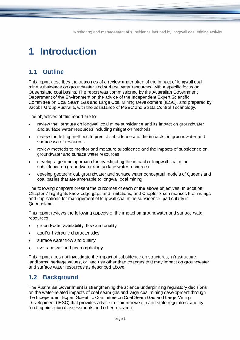
1.1 Outline
This report describes the outcomes of a review undertaken of the impact of longwall coal mine subsidence on groundwater and surface water resources, with a specific focus on Queensland coal basins. The report was commissioned by the Australian Government Department of the Environment on the advice of the Independent Expert Scientific Committee on Coal Seam Gas and Large Coal Mining Development (IESC), and prepared by Jacobs Group Australia, with the assistance of MSEC and Strata Control Technology.
The objectives of this report are to:
review the literature on longwall coal mine subsidence and its impact on groundwater and surface water resources including mitigation methods
review modelling methods to predict subsidence and the impacts on groundwater and surface water resources
review methods to monitor and measure subsidence and the impacts of subsidence on groundwater and surface water resources
develop a generic approach for investigating the impact of longwall coal mine subsidence on groundwater and surface water resources
develop geotechnical, groundwater and surface water conceptual models of Queensland coal basins that are amenable to longwall coal mining.
The following chapters present the outcomes of each of the above objectives. In addition, Chapter 7 highlights knowledge gaps and limitations, and Chapter 8 summarises the findings and implications for management of longwall coal mine subsidence, particularly in Queensland.
This report reviews the following aspects of the impact on groundwater and surface water resources:
groundwater availability, flow and quality
aquifer hydraulic characteristics
surface water flow and quality
river and wetland geomorphology.
This report does not investigate the impact of subsidence on structures, infrastructure, landforms, heritage values, or land use other than changes that may impact on groundwater and surface water resources as described above.
1.2 Background
The Australian Government is strengthening the science underpinning regulatory decisions on the water-related impacts of coal seam gas and large coal mining development through the Independent Expert Scientific Committee on Coal Seam Gas and Large Mining Development (IESC) that provides advice to Commonwealth and state regulators, and by funding bioregional assessments and other research.

Monitoring and management of subsidence induced by longwall coal mining activity
page 2
The IESC was appointed to provide scientific advice to government agencies responsible for regulating coal seam gas and large coal mining proposals that are likely to have significant impacts on water resources. The functions of the IESC are described fully in Section 505D of the Commonwealth Environment Protection and Biodiversity Conservation Act 1999 (EPBC Act 1999) (Commonwealth of Australia 1999). The Office of Water Science (OWS) within the Department of the Environment supports the IESC.
As well as providing advice on coal seam gas and large coal mining development proposals, the IESC advises on the scope and method of the bioregional assessments being undertaken in areas where coal seam gas and/or large coal mining developments are underway or planned. Bioregional assessments are a scientific analysis of the ecology, hydrology and geology of an area. Their purpose is to assess the potential cumulative risks to water resources as a result of intended developments.
The IESC also provides advice on research priorities to address critical gaps in scientific understanding of the water related impacts associated with coal seam gas and large coal mining activities. These priorities form the basis of the OWS research agenda.
This review of the impact of longwall coal mine subsidence on groundwater and surface water resources, with a specific focus on Queensland coal basins, is a research project commissioned by the OWS under the Hydrology theme identified by the IESC as a research priority.

Monitoring and management of subsidence induced by longwall coal mining activity
page 3
2 Review of subsidence impacts on groundwater and surface water resources
2.1 Longwall coal mining method
This section provides a summary of the longwall coal mine method, where it has been applied and its advantages and disadvantages compared to other underground coal mining methods.
The locations of coal resources in Australia are presented in Figure 2.1. Underground coal mining and longwall extraction are restricted to the coal basins of NSW and Queensland. Potential underground coal resources are known in South Australia and Western Australia, but there are no plans to exploit these by longwall mining due to their depth, low quality and/or remoteness from rail transport (Australian Mining 2008). Although Victoria and South Australia have significant coal deposits (especially in the Latrobe Valley), they are close enough to the surface to be mined using the open cut method (Doyle 1986).
Underground coal mines in NSW and Queensland generally work a single seam, although multi-seam mining is becoming more common (MSEC 2007a). Coal seams are relatively flat-lying, relatively undisturbed, and typically 2 to 6 m thick. Typical extracted seam thicknesses range from 2 to 4.5 m, although with the availability of coal caving techniques (i.e. natural collapse of the upper seam) even thicker coal seams of up to 9 m could be mined in one pass (Mills 2009; Holla & Barclay 2000). The latter method has significant implications in terms of greatly increased surface subsidence, but is not yet in use in Australia.
NSW mining depths are now mostly in the range 200 to 600 m, although prior to the 1980s less than 300 m was the standard. Whilst there are current proposals to mine seams at depths up to 690 m in NSW, Queensland mines tend to be shallower and the seams tend to be thicker—typically 3 m or more, compared to about 2 m in NSW (Nicholls 2001).
The main methods of underground coal mining include:
Bord and pillar first workings: involves driving tunnels (roadways and branching cut-throughs) to outline a network of pillars like the tiles on a floor. Some of these pillars will be permanent – to protect roadways and establish barriers – and some, usually much larger, will be taken during the second working pillar extraction phase.
Various partial pillar extraction methods (second workings) and Wongawilli Method: such as using continuous miners (excavation machines) with or without various remote supports or flexible conveyor systems.
Longwall mining (discussed in more detail below).

Monitoring and management of subsidence induced by longwall coal mining activity
page 4
© Copyright, Jareth and Huleatt (2012)
Figure 2.1 Australian coal resources

Monitoring and management of subsidence induced by longwall coal mining activity
page 5
Longwall mining is a method used to extract large rectangular panels (i.e. blocks) of coal, typically 150 to 400 m wide and 1 to 4 km long. The coal is progressively mined by a shearer that shaves off slices of coal up to 1 m thick to the full height of the face, typically 2 to 4.5 m, under the protection of hydraulic supports, until the panel is fully extracted. Operations at the coal face are illustrated in Figure 2.2.
While the technology has changed considerably over the years, the basic principle of longwall mining is to maintain a safe working space for miners along a wide coal face whilst removing coal and allowing the roof and overlying rock to collapse into the void behind the hydraulic supports (Kininmouth & Baafi 2009).
A cutaway view of a typical longwall mine is shown schematically in Figure 2.3.
© Copyright, MSEC (2007a)
Figure 2.2 An operating longwall coal mine face

Monitoring and management of subsidence induced by longwall coal mining activity
page 6
© Copyright, MSEC (2007a)
Figure 2.3 Schematic cutaway view of a typical longwall coal mine
The longwall mining method first requires a large rectangular pillar (the longwall panel) to be formed using a continuous miner machine. Gateroads (ventilation and haulage tunnels) are then driven on both sides of each panel. Panels are normally laid out in parallel series of 3 to 6 panels across a seam to minimise the length of development or gateroads, with chain pillars between them (Mills 2011). A typical longwall mine layout is shown in Figure 2.4.

Monitoring and management of subsidence induced by longwall coal mining activity
page 7
© Copyright, NSW DoP (2008)
Figure 2.4 Plan layout of a typical longwall mine, also showing some bord and pillar workings
A line of self-advancing powered hydraulic jacks, called chocks or shields, provide support to the roof along the coal face at one end of the longwall panel. An image of these, with the coal shearer, conveyor and hydraulic support chocks, is shown in Figure 2.5. Each support is typically 1.75 m wide and many supports are placed in a line, side-by-side, for the full width of the coal face, as depicted in Figure 2.6. An individual support can weigh 30 to 40 tonnes, can extend to a maximum cutting height of 4.5 m in Australia, and can support 1000 tonnes or more of the overlying strata weight. Each chock can hydraulically advance itself around 1 m forward after each slice of coal is extracted (Peng & Chiang 1984), resulting in a snake-like progress of the line of chocks.

Monitoring and management of subsidence induced by longwall coal mining activity
page 8
© Copyright, Dowty Supports, UK
Figure 2.5 Typical shearer, conveyor and hydraulic support chocks
© Copyright, Dowty Supports, UK. The pictured chock shields have two hydraulic legs, but four legged supports are also common
Figure 2.6 A line of hydraulic longwall face supports, each about 1.75 m wide, which can each move forward sequentially in a snaking motion
As the longwall face progresses through the seam in a snake-like ‘side-winding’ motion, the overlying roof strata falls into the mined void (i.e. goaf) behind and subsidence of the overlying strata commences. The collapsed roof strata comprise loose blocks and can contain voids, depending on the loading and compaction that follows. Immediately above the mined void and the collapsed zone, the strata can remain relatively intact and bend into the

Monitoring and management of subsidence induced by longwall coal mining activity
page 9
void, resulting in new vertical fractures, the opening up of existing vertical fractures, and bed separation. The strata layers above that bend and shear with the amount of sagging, fracturing and bed separation reduce towards the surface.
Figure 2.7 shows a cross-section of a typical longwall face showing a coal seam under extraction and the fracturing occurring as the overlying strata collapse into the goaf.
© Copyright, MSEC (2007a)
Figure 2.7 Cross-section of a typical longwall showing the fracturing occurring as the overlying strata collapse into the goaf
Longwall coal mining is now the most common underground coal mining technique in Australia (Mitchell 2009). It now produces about 80 per cent of the underground coal in NSW (DTI 2010) and the majority of proposed underground mines in both NSW and Queensland are likely to be longwall coal mines (Australian Mining 2008).
Although longwall mining comes with a high capital cost and causes widespread and sometimes damaging subsidence, it has the following benefits (Peng & Chiang 1984):
Longwall mining is an operational necessity at great depths (i.e. more than 300 to 400 m), since the large diameter protective pillars required for conventional bord and pillar workings at these depths make bord and pillar mining uneconomic (Peng & Chiang 1984).
Other hazards of deep mining, such as high lateral stresses and heavy abutment (panel edge) loadings, and greatly increased face gas emissions, can also be better managed by longwall layouts (Peng & Chiang 1984). However, successful longwalls require much more geological and rock mechanics investigation ahead of mining compared to bord and pillar mines (Peng 1986).
The longwall method is the most efficient form of underground coal resource extraction, with seam recovery more than 90 per cent by area under favourable conditions. Other bord and pillar methods may yield only half the amount of coal from the same seam area
Monitoring and management of subsidence induced by longwall coal mining activity
page 10
(Peng & Chiang 1984). Increasing yields in bord and pillar workings by a final stage of pillar removal can be hazardous.
Longwall mining has proven to be safer for miners per unit of production compared to other underground coal extraction methods (Kininmouth & Baafi 2009).
Most of the subsidence above a moving longwall occurs quickly, within a few days for the most damaging (tensile) phase of the cycle, and is relatively predictable. Even in the final consolidation phase, due to adjacent panel extraction, subsidence will cease within 1 to 2 years in most cases. By contrast, subsidence of bord and pillar workings may occur decades after mine abandonment (Waltham 1989).
Longwall mining seals off gas-filled goafs and prevents self-heating that arises due to oxidation in mines closer to the surface (once a serious hazard on the Cessnock Coalfield and even now a problem at Ipswich; Farmer 1985; Peng 1986).
2.2 Longwall coal mining subsidence
This section details the mechanisms involved in subsidence induced by longwall coal mining and some of the parameters used to measure and characterise subsidence. There is also a discussion on the important factors in the degree and timing of subsidence.
2.2.1 Subsidence mechanisms
2.2.1.1 Underground mechanisms causing subsidence
When a single roadway or tunnel is driven into a coal seam, the pressures or loads originally carried by the extracted area are transferred to the solid coal sides, as illustrated in Figure 2.8. As a mine develops with an increasing number of roadways, the coal that is left between each area of extraction forms a load-bearing pillar. The average pillar loading will increase as the percentage of coal extracted by area increases (Peng 1986). This extra load results in compression of the coal seam and the immediate roof and floor strata of the coal seam around the perimeter of the excavation. Note the convergence of stress lines above the excavation edges in Figure 2.8. This is often referred to in the literature as abutment stress (Whittaker & Reddish 1989).

Monitoring and management of subsidence induced by longwall coal mining activity
page 11
© Copyright, Whittaker and Reddish (1989). The view illustrated is of a single longwall panel, whose long axis (the centre line of the mined panel) is perpendicular to the page.
Figure 2.8 Redistribution of forces around a narrow excavation
The mined-out void progressively becomes too wide to be self-supporting and the immediate roof strata sag and separate along bedding planes then collapse into the void. Figure 2.9 illustrates a physical model of extraction by longwall methods, with mining proceeding from left to right. Note that the width of extraction is not yet wide enough for subsidence to have reached the surface; the extraction is said to be subcritical. Another feature to note is the delamination gap and associated bridging at the top of the subsided strata, which would normally occur immediately beneath a stronger, more competent formation (Whittaker & Reddish 1989).
© Copyright, Whittaker and Reddish (1989)
Figure 2.9 Physical model of subsided longwall panel being extracted from left to right

Monitoring and management of subsidence induced by longwall coal mining activity
page 12
Coal extraction, whether by longwall or bord and pillar methods, removes support from the overlying roof strata, and thereby generates an ellipsoidal or inverted trapezoidal mass of sagged, broken and sheared rock above the seam cavity (Forster 1995; Forster & Enever 1992). The more common trapezoidal profile of caved strata, terminated upwards by a thick bridging layer, is illustrated in Figure 2.9. Ellipsoidal caving profiles are characteristic of thin bedded, weak roof strata such as mudstone or shale.
A generalised conceptual model of caving, subsidence and variation in rock mass fracturing and its effect on rock mass permeability is presented in Figure 2.10. It was first put forward in the 1960s and was widely supported at that time. Extensive field investigations were undertaken involving borehole extensometer work to try to quantify the various zones (ACARP 2000; Holla & Armstrong 1986). As a generalised model it appears to be a reasonable representation of the various regions of subsidence. However, the various regions shown in this figure may vary according to site-specific conditions present at a particular mining operation (Creech 1995; Booth 1986, 2002). It is essential to understand the differences in geology and mining conditions when comparing various sites to this conceptual model.
© Copyright, Forster (1995). The view illustrated is of a single longwall panel. The long axis (the centre line of the mined panel) is perpendicular to the page
Figure 2.10 Caving, fracturing and subsidence above a longwall panel
The actual amount of downward movement for a deep longwall mine is typically 1 to 2 m, but could be 2 to 3 m for a thick seam mined at shallow depth, depending on a number of factors such as the depth of cover and the panel and pillar sizes (Holla & Barclay 2000). Surface movement results from a combination of sag of the roof strata into an excavation and compression of the strata that comprise the abutments of the excavation. This results in surface movement extending beyond the footprint of the mine excavation. In practice, coal

Monitoring and management of subsidence induced by longwall coal mining activity
page 13
mine workings effectively comprise a series of voids separated by pillars, and so surface movement is determined by both excavation behaviour and the behaviour of the coal pillars and the strata above and below them (Mills 2009; Waltham 1989).
Vertical subsidence generally does not cause surface damage. Rather, the damage to structures at the ground surface is usually the result of tilting and stretching, which precedes the onset of vertical settlement, and by the re-compression which follows it (Whittaker & Reddish 1989; NCB 1966, 1975). Flooding of nearby low-lying land as a result of near-shore subsidence is the exception. This occurred at Chain Valley Bay and Buff Point NSW in 1986 and 1990 respectively, though as a result of pillar mining rather than longwall coal mining (MSB, no date).
2.2.1.2 Subsidence profile
Tilt, vertical subsidence, upsidence, horizontal displacement, curvature and strain are the parameters normally used to define the extent of surface movements that occur as mining proceeds, and generally form the basis for assessing the effects of subsidence on surface infrastructure (NCB 1966, 1975; Galvin 1987a, 1987b, 1988). The relationship between these parameters is illustrated schematically in Figure 2.11 which shows a typical subsidence profile drawn to an exaggerated vertical scale. The view illustrated is of a single longwall panel for which the long axis (centre line) is perpendicular to the page.
© Copyright, NCB (1975). Note that depictions of all parameters (subsidence, tilt, curvature, horizontal movement and horizontal strain) are at the ground surface. Image not to scale
Figure 2.11 Development of subsidence parameters in relation to the mining void geometry
Figure 2.11 illustrates the subsidence profile in only two dimensions. In reality, this type of profile extends longitudinally down the length of a mining panel and also transversely across the width of the panel. Therefore, points on the surface can be subjected to displacement in three dimensions within a subsidence trough.

Monitoring and management of subsidence induced by longwall coal mining activity
page 14
2.2.1.3 Anomalous movements
Anomalous ground movements are spikes or other departures from systematically or conventionally smooth subsidence profiles. They may or may not affect groundwater and surface water resources depending on site conditions. Apart from variations in overburden geology and topographic effects, profile anomalies may be due to:
gravitational movement of subsided overburden towards old mine workings, which may be either in the same seam or below. One spectacular example was the 2.3 m of subsidence beneath the Pacific Highway at Doyalson in 1988, caused by longwall induced collapse of pillar remnants in a higher seam (Holla & Barclay 2000)
shuffling and jostling of near-surface joint blocks or rock slabs, causing small but potentially damaging steps and mounding. Stress relief at shallow depth in such rocks, where the horizontal stress may be up to 10 times the vertical stress, may cause localised upwards bulging, and buckling resulting in rock layers becoming loosened and breaking into joint bounded slabs (MSEC 2007b, 2008)
survey errors, displaced or replaced pegs, or simply changes in peg spacing. Movement of pegs by clay soil shrink and swell, or by down slope creep, may also contribute to non-systematic movements (MSEC 2007b, 2008).
2.2.2 Subsidence parameters
Taking Figure 2.11 as a starting point, relevant parameters are summarised below and are also discussed in more detail in Whittaker and Reddish (1989) and NCB (1975). Subsidence parameters in the Australian mining experience are discussed in detail in MSEC (2007a) and MSEC (2008).
Subsidence (S)
Subsidence refers to the vertical displacement of a point. Note that the actual movement of the ground includes both vertical and horizontal components. Horizontal displacements can in many cases be greater than the vertical subsidence, particularly where the subsidence is small or occurs beyond the panel edges. The amplitude of subsidence is usually expressed in millimetres (mm).
Maximum subsidence (Smax)
When values of vertical displacement (subsidence) are quoted, they usually refer to Smax, even though much smaller subsidence values are commonly recorded, especially at the edge of the subsidence trough. Smax is usually expressed in mm and is typically measured by levelling along survey lines.
Horizontal displacement
The horizontal component of surface movement, or horizontal displacement, is greatest at the point of maximum tilt and declines to zero at the limit of subsidence and at the point of maximum subsidence (i.e. at the leading edge of the subsidence wave and at its trailing edge). Horizontal displacement is usually expressed in mm.
Subsidence factor
This is the ratio of the maximum subsidence measured at the surface to the mined thickness (Smax/T, where T is the thickness of the seam mined). It is typically 50 to 65 per cent in the
Monitoring and management of subsidence induced by longwall coal mining activity
page 15
Sydney Basin, but depends on the extraction widths of panels and competency of the overburden. Conversely, the subsidence factor may locally approach 90 per cent in some softer rocks in the Bowen Basin – as it does in the United Kingdom (UK). Future multi-seam longwall mining may also register high subsidence factors, as remobilisation of an upper seam goaf is triggered by undermining.
Tilt (G)
Tilt is calculated as the change in subsidence between two points divided by the horizontal distance between those points. Tilt is the first derivative of the subsidence profile. The sign of tilt is generally not important, but the convention usually adopted is for a positive tilt to indicate the ground increasing in subsidence in the direction of measurement. Tilt is usually expressed in units of millimetre per metre (mm/m).
The maximum tilt, or the steepest portion of the subsidence profile, occurs at the point of inflection in the subsidence trough, where the subsidence is roughly half of the maximum subsidence. The magnitude of tilt is critical to the impact on nearby buildings and infrastructure. In general, buildings and roads are less tolerant to differential settlements (induced by tilt) compared to total vertical settlement (subsidence) and thus tilt is a key parameter to be assessed for structural damage resulting from mining.
Curvature
Curvature is the second derivative of subsidence, or the first derivative (rate of change) of tilt, and is calculated as the change in tilt between two adjacent sections of the tilt profile divided by the average length of those sections. Curvature is usually expressed as the inverse of the radius of curvature with the units of 1/km, or km-1, but the value of curvature can be inverted, if required, to obtain the radius of curvature, which is usually expressed in kilometres.
Strain (E)
Strain is caused by shearing (shear strains) and differential horizontal movements (normal strains) in the near-surface strata. Shear strains are often neglected as they result in no net extension or compression at the surface. Conversely, normal strains can be thought of as localised ground stretching (tensile strain) or shortening (compressive strain). It is determined by dividing the change in length between pegs on a survey line by the initial horizontal length of that section. Strain is measured in mm/m.
If peg spacing extends, the ground is under tension and the resulting strain is positive (+E). If peg spacing shortens, the ground is under compression and the resulting strain is negative (-E).
Maximum surface strains coincide with the maximum curvature and hence the maximum tensile strains occur towards the sides of the panel whilst the maximum compressive strains occur towards the bottom of the subsidence trough.
Point of flexure
The point of flexure, or inflection, on the subsidence profile marks the transition from the tensile to the compressive parts of the subsidence pattern. It is also the approximate point of half-subsidence (0.5 Smax) on the profile.

Monitoring and management of subsidence induced by longwall coal mining activity
page 16
Angle of draw (AoD)
AoD is a subsidence engineering term used to define the observed limits of the subsidence trough. It is determined from a plot of measured subsidence versus distance along the surveyed monitoring lines (Holla 1985, 1988).
Because small surface movements can also be caused by natural effects, such as seasonal swelling or shrinkage of soil due to moisture changes, it can be very difficult to identify where vertical movement due to mining ceases. In situ horizontal stresses in the bedrock also affect the magnitude of the observed angles of draw, since small horizontal displacements and vertical relaxation can occur beyond goaf areas (far-field movements). Far-field movements may be detectable up to 2 km from the edge of the mining panel, though they are greatest within 500 m (Hebblewhite et al. 2000).
It is standard practice to specify a limiting value for vertical displacement which might be attributable to mining. In NSW this value is usually 20 mm of permanent vertical subsidence (Holla & Barclay 2000). It should be noted that in some environments, up to 50 mm or more of vertical movement may occur due to seasonal moisture changes (Holla & Barclay 2000). AoD varies with geology and depth of cover and typically ranges from a few degrees (i.e. a near-vertical step at the panel edge) up to 60 degrees, but is most commonly in the range of 20 to 35 degrees (MSEC 2007a, 2008).
NSW adopts a generalised AoD of 26.5 degrees if no better information is available (MSEC 2007a), since this angle predicts the subsidence trough extending to half the mining depth beyond the edge of mining. That angle is also close to the average AoD in the Sydney Basin (MSEC 2007a; Holla & Barclay 2000). In general, the stronger the overburden rocks or the shallower the mining, the smaller the AoD. (D Kay 2013, pers. comm., 21 April)1. With weak and thinly bedded strata and where deep soils are present at the surface, the AoD may increase beyond 35 degrees (D Kay 2013, pers. comm. 21 April).
The concept of AoD should not be used alone to protect groundwater and surface water resources. It is only a measurement of the limit of commonly observed or predicted vertical subsidence movements. Many additional steps need to be taken to protect groundwater and surface water resources from subsidence effects. However, angle of draw can be a useful concept for designing mine layouts such that specific assets at the surface (e.g. dams) can be protected from subsidence impacts. For example, the IESC recommended a conservative 45 degree AoD be adopted for the Russel Vale project in NSW.
Incremental, cumulative, total and transient parameters
The incremental subsidence, tilts, curvatures and strains are the additional parameters which result from the extraction of a series of longwall panels. Longwall panels are usually arranged in a parallel series of three to six panels, such that an underground mine district might be 1200 to 2500 m across (NSW DoP 2008).
The cumulative subsidence, tilts, curvatures and strains are the accumulated parameters which result from the extraction of a series of adjacent longwall panels.
1 Kay, D. Director, Mine Subsidence Engineering Consultants, Level 1, 228 Victoria Avenue, Chatswood, NSW,
2067.

Monitoring and management of subsidence induced by longwall coal mining activity
page 17
The total subsidence, tilts, curvatures and strains are the final parameters at the completion of a series of longwalls or panels and can include the total movements from multi-seam mining conditions.
Transient tilts, curvatures and strains are the travelling or short duration movements that occur as the longwall face passes directly beneath a given point.
2.2.3 Surface subsidence development
The subsidence phenomenon can be likened to a solid wave which moves across the landscape at typically 50 to 100 m per week, in step with the longwall face immediately below, leaving behind a shallow, flat-bottomed, rectangular trough. This movement has been captured on time-lapse photography in South Africa (JM Galvin 1995, pers. comm.)2, though it is less obvious in timbered country such as the NSW coal mining regions. Below and behind the subsidence wave the overburden layers sag and partially break-up and slide into the mining void or goaf.
2.2.3.1 The subsidence process
Subsidence at the surface develops progressively. General descriptions of the subsidence process and mechanisms are provided in Whittaker and Reddish (1989), Waltham (1989), and Peng and Chiang (1984). A summary of the information in these references is provided below.
To follow the process of subsidence, consider a single point—usually a survey peg hammered flush to the ground—located on the centre line of the first longwall panel in a series (as shown in Figure 2.12). As the mining face approaches the observation point, slight downward movement becomes detectable 100 to 200 m ahead of the face. Where bedrock is present beneath a thin soil cover there may even be a measurable upward bulging due to jostling of near-surface joint blocks.
As the mine face passes beneath the point, subsidence increases rapidly. The ground stretches (tensile strain) and may develop open cracks, especially if the soil is thin. Where the panel is shallower than about 200 m, these tensile cracks become conspicuous. The ground tilts away from the direction of face movement, though this may not be obvious to the observer since the maximum inclination is typically about one unit vertical to 30 units horizontal (1V:30H, or a 3.3 per cent grade).
In addition to vertical movement, which is easy to measure by levelling and was thus the only parameter formerly recorded by NCB (1975), there is a horizontal component of ground displacement which moves the peg rearwards. At the panel edges, but not on the centre line, there may even be partial rotation of survey pegs. All of this movement takes place within a few days of the face passing beneath the observation point.
At about 100 to 200 m behind the face, say two weeks after undermining, the ground becomes once again compressed as the underlying strata cease their readjustment. During this compressive phase most of the tensile cracks close and some slight mounding might be visible. Beneath the surface bedrock, fractures likewise close, but do not regain their pre-mining fit; hence both the porosity and permeability of the shallow bedrock increase. This is of great importance to understand when considering groundwater impacts.
2 Professor Jim Galvin, Head of School, School of Mining Engineering, University of NSW. Sydney, Australia.
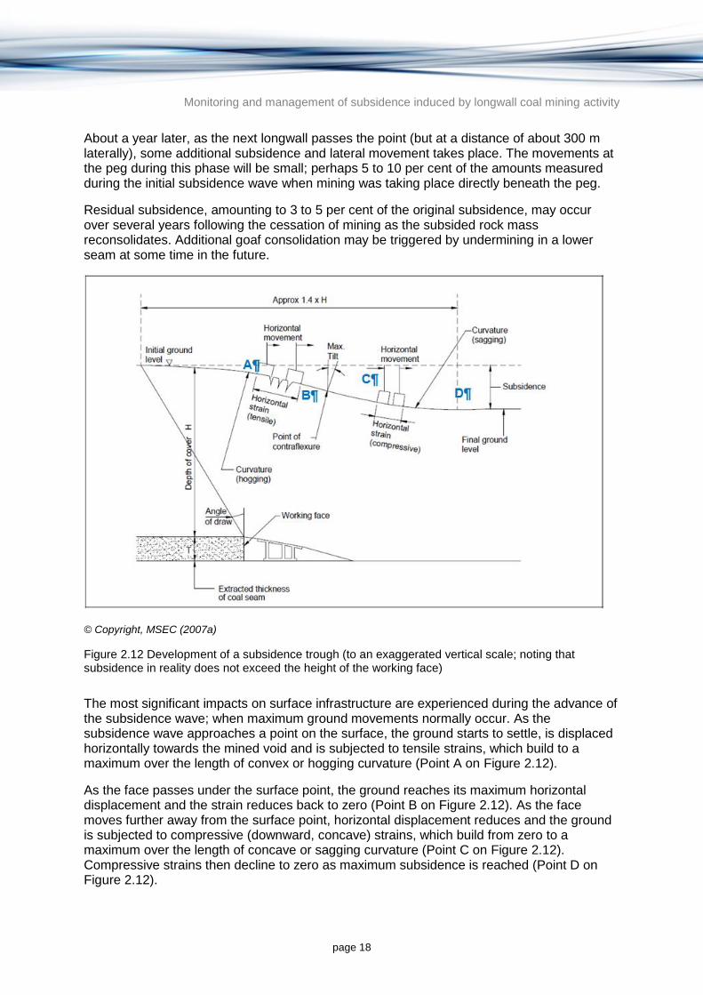
Monitoring and management of subsidence induced by longwall coal mining activity
page 18
About a year later, as the next longwall passes the point (but at a distance of about 300 m laterally), some additional subsidence and lateral movement takes place. The movements at the peg during this phase will be small; perhaps 5 to 10 per cent of the amounts measured during the initial subsidence wave when mining was taking place directly beneath the peg.
Residual subsidence, amounting to 3 to 5 per cent of the original subsidence, may occur over several years following the cessation of mining as the subsided rock mass reconsolidates. Additional goaf consolidation may be triggered by undermining in a lower seam at some time in the future.
© Copyright, MSEC (2007a)
Figure 2.12 Development of a subsidence trough (to an exaggerated vertical scale; noting that subsidence in reality does not exceed the height of the working face)
The most significant impacts on surface infrastructure are experienced during the advance of the subsidence wave; when maximum ground movements normally occur. As the subsidence wave approaches a point on the surface, the ground starts to settle, is displaced horizontally towards the mined void and is subjected to tensile strains, which build to a maximum over the length of convex or hogging curvature (Point A on Figure 2.12).
As the face passes under the surface point, the ground reaches its maximum horizontal displacement and the strain reduces back to zero (Point B on Figure 2.12). As the face moves further away from the surface point, horizontal displacement reduces and the ground is subjected to compressive (downward, concave) strains, which build from zero to a maximum over the length of concave or sagging curvature (Point C on Figure 2.12). Compressive strains then decline to zero as maximum subsidence is reached (Point D on Figure 2.12).

Monitoring and management of subsidence induced by longwall coal mining activity
page 19
When the subsidence processes are complete, the ground is commonly left with almost no horizontal displacement and little residual tilt or strain. Between the tensile and compressive zones is the point of inflection (Point B on Figure 2.12) which is the point at which maximum tilt and maximum horizontal displacement occurs. For critical extraction conditions, it is also the point at which the subsidence is approximately half the maximum subsidence.
As the longitudinal wave passes, the transverse subsidence profile gradually develops and is completed as maximum subsidence is reached. The transverse subsidence profiles over each side of the panel are similar in shape to the longitudinal subsidence profile and have the same distribution of tilts, curvatures and strains. Most points on the surface will thus be subjected to three-dimensional movements, with tilt, curvature and strain in both the transverse and longitudinal directions. The impact of subsidence on surface infrastructure is therefore dependent on its position in the trough.
The sequence of ground movements described above applies to the central part of the panel, (i.e. on the floor of the subsidence trough). Towards the edges of the panel the impacts in both the transverse and longitudinal direction are reduced. If a structure is located on the perimeter of the subsidence trough, it will experience less settlement but may suffer permanent tilt and strain.
A structure or surface feature on the side of the trough between the tension and compression zones will experience some subsidence, and will be left with residual horizontal displacement and tilt, but will be subjected to lower curvatures and strain. Structures or surface features located at the positions of maximum curvature and strain would generally suffer the greatest impact.
2.2.3.2 Multiple panels
As each longwall panel within a mine is extracted in turn, an incremental subsidence trough is formed above it. If the width-to-depth ratios of the panels are low, the incremental subsidence troughs overlap at the surface and the resulting subsidence at any point is a combination of their effects. Each point will be subjected to a series of subsidence waves, the impacts of which will depend upon the position of the point relative to each of the subsidence troughs (NCB 1966, 1975).
Overburden is usually made up of near-horizontally bedded strata. Sag results in each stratum being ‘stretched’ and placed into tension. The relative weakness of rock when under tension is conducive to the opening up and lateral extension of existing geological joints, and the formation of fresh, near-vertical fractures. In the process of sagging, shearing also occurs along the bedding planes between and within the various strata. These sliding surfaces can develop into open cracks, which may widen if the lower bed sags more than the adjacent upper bed. Hence, a well developed and connected vertical and horizontal fracture network is likely to develop in the rock mass immediately overlying the caved material in a goaf (D Kay 2013, pers. comm.).
2.2.3.3 Mining induced surface cracking
Longwall mining can result in cracking, heaving and buckling at the surface, especially where the soil cover is thin. Deep soil can mask bedrock cracking (McNally 1996a). Surface deformations are influenced by factors such as ground curvature and differential horizontal movement, which are in turn dependent on the mining geometry, depth of cover, extracted seam thickness, nearby topography and subsurface geology (Whittaker & Breeds 1977; McNally et al. 1996a).
Monitoring and management of subsidence induced by longwall coal mining activity
page 20
Surface crack widths and frequencies may also reflect jointing patterns in the bedrock. Wide natural joint spacing can lead to concentrations of strain and possible development of new fractures at rock head (NCB 1975; Ditton 2011). Mining induced subsidence can cause fresh fracturing in the overlying rock and also buckling of the near-surface beds during the compressive phase of the subsidence wave (McNally et al. 1996a). As a subsidence trough develops, surface cracks will generally appear in the tensile zone, typically parallel to and 0.1 to 0.4 times the depth of cover in from the panel edges (D Kay 2013, pers. comm.).
At shallow depths of cover, surface cracking and heaving can potentially occur in any location above the extracted longwalls. Larger and more permanent cracks, however, are usually located in the final tensile zones around the perimeters of the panels. Open fractures and heaving, however, can also occur due to buckling of surface beds that are subject to compressive strains (McNally et al. 1996a).
In the Queensland context, the strength of rock varies across the Bowen Basin. Where the overburden includes high strength sandstone units with significant spanning capacity, fractures will form at wider spacing than that normally observed in NSW (D Kay 2013, pers. comm.). For example, surface crack widths up to about 100 mm and step heights in the order of 100 mm have been commonly observed at shallow depths of cover (less than 200 m). Even wider cracks have been observed in collieries of the Bowen Basin where thick seams are extracted in steep terrain (ACARP 2000). These larger tensile cracks tend to be located around the perimeters of the longwall panels and along the tops of steep slopes, and can usually be identified and plugged to help mitigate loss of surface water (ACARP 2000).
2.2.4 Factors influencing mine subsidence
The following list of factors includes the main parameters that influence mine subsidence (NCB 1966, 1975).
Mining and geometrical factors
depth of cover
panel width
pillar width
panel width to depth ratio
seam thickness extracted
proximity of adjacent, previously mined panels in current seam
proximity of adjacent, previously mined panels in other seams (multi-seam conditions).
Geological and topographical factors
geological properties of overburden, including strength and thickness of layers
coal properties including strength and seam inclination
presence of natural joints
presence of faults
presence of thick massive conglomerate, sandstone or igneous sills
presence of intrusive dykes
coal seam floor conditions, presence of soft and/or water sensitive floor
Monitoring and management of subsidence induced by longwall coal mining activity
page 21
strength of immediate roof of coal seam
surface topography with particular reference to escarpments, cliffs, and gorges.
2.2.4.1 Impact of mine geometry
Subsidence measured at the ground surface is closely related to longwall mining geometry—i.e. to the depth, seam working height, extraction panel width and pillar dimensions. In the course of subsidence monitoring in the UK (NCB 1975; Holla & Barclay 2000), based largely on levelling pegs 5 to 20 m apart, it was found that:
maximum vertical movement developed along the centre of a longwall panel, but diminished towards the perimeter and beyond.
maximum subsidence was directly related to the thickness of coal, as might be expected, but also to the mining width and depth. Subsidence at ground level was found to be 50 to 90 per cent of the worked seam thickness in the UK, though it is typically only 50 to 60 per cent in Australia.
maximum subsidence was not achieved until the mined-out width was greater than 1.4 times the seam depth. Reaching this critical width of extraction usually required mining two or three panels.
subsidence might be retarded if wide pillars were left between the longwall panels, or even reduced to a small proportion of the worked thickness if very broad pillars and a narrow longwall face were adopted.
vertical movements measured along longitudinal and transverse survey lines could be compiled into a series of profiles illustrating the passage of subsidence waves across the land surface.
From these results, the measured parameters T (seam working thickness) and Smax (maximum subsidence) can be related to mining panel geometry (depth of cover (H) and mined width (W)). In addition, parameters such as maximum tensile and compressive ground strains (+Emax, -Emax) and maximum tilt (Gmax) could be derived (NCB 1975; Holla & Barclay 2000; Mills 2009).
2.2.4.2 Subcritical, critical and supercritical extractions
During longwall mining, a stage is reached where the full dead weight of the overburden rests on the compacted caved material and a point of maximum possible vertical subsidence is reached. This excavation width is referred to as the critical span or critical width. As further increases in excavation width causes negligible additional sag of the overburden, this width is referred to as the supercritical span (NCB 1975).
An extraction area can be termed subcritical, critical or supercritical (Mills 2009; Whittaker & Reddish 1989). A critical extraction is one where the panel width is sufficiently large compared with the mining depth to produce the maximum possible subsidence at the centre of the panel. In other words, full subsidence is only achieved when the width of extraction, which may encompass several side-by-side panels, exceeds a certain critical value. Extraction widths smaller than critical are termed subcritical (Whittaker & Reddish 1989).
Subcritical extraction has long been common practice in the Sydney Basin of NSW, where it is often specified to minimise subsidence close to residential areas. It is also required where there is a risk of damage to surface waters; to protect groundwater dependent ecosystems; or where there is a risk of flooding in the mine (Atkinson 1902). Typical ratios of the width of

Monitoring and management of subsidence induced by longwall coal mining activity
page 22
the longwall panel to the depth of the mine (W/H ratio) in the Newcastle area range from 0.3 to 0.8, and the resulting subsidence may be only 10 to 50 per cent of the maximum possible value. This is reflected in greatly reduced cracking in the overburden and, hence, less risk of drainage of surface or groundwater into mine workings. However, there is a 'danger zone' for subsidence prediction, since a small increase in the W/H ratio above about 0.6, or the thinning of a bridging conglomerate layer, can cause subsidence to increase greatly (Ditton 2011; Creech 1995). Subsidence mechanisms in this situation are poorly understood, but vertical movement is probably controlled partly by the elastic properties of the overburden, partly by its fracturing behaviour, and perhaps mostly by the stiffness of the coal pillars (Mills 2009).
Mills (2009) has summarised the relationship between depth of mining, extraction width and subsidence as follows:
at W/H > about 1.6, maximum subsidence (Smax, typically 55 to 65 per cent of the mined seam thickness) is achieved
at W/H = 0.6 to 0.4 the surface is largely supported and subsidence can be held to about 10 per cent of the maximum
at W/H < 0.4 the amount of surface subsidence is negligible.
The above generalisations can be incorrect at extreme depths and in complex geological settings. As such, W/H considerations should always be based on the actual depth of cover and should never be used as the only predictor of subsidence.
2.2.4.3 Geological and topographical factors influencing subsidence
Overburden factors are difficult and expensive to quantify so geological explanations of subsidence phenomena are often sought only when empirical or numerical modelling predictions (discussed later in this report) fail to match actual measurements. While geology may have little effect on vertical movement—the subsidence parameter most commonly recorded—it can have a great influence on the more structurally damaging parameters: lateral movements, horizontal strains, ground curvature and tilt. McNally (1996b) stated that the geological factors influencing ground response to mining induced caving include:
overall lithology, particularly the presence or absence of massive sandstone or conglomerate beds, and hence the overall stiffness and tensile strength of the overburden in its unsubsided state
geological structure of the overlying and underlying rock mass, primarily the bulking capacity, the intensity of joints and bedding, and their geotechnical properties (such as shearing resistance, persistence and spacing)
seam dip
faults and dykes: linear and usually vertical geological features have a specific influence on the character of surface subsidence, in that they concentrate strain and differential movement along their surface trace
depth and type of soils overlying the coal strata. These influence the surface movements, ground strains and the spread of the subsidence trough
surface topography and seam dip. Steep surface topography may cause tensile strains to increase along ridge lines and close to cliffs, and cause compressive strains to increase in valleys. Steep topography and seam dips can distort the subsidence profile and may even cause valley floor uplift near the mining panel.

Monitoring and management of subsidence induced by longwall coal mining activity
page 23
The influence of geology on mining induced subsidence in Australian coal basins is complicated by the effects of shallow mining, partial extraction and uneven surface topography. However, a number of conclusions may be drawn.
First, the main geological factor influencing surface movements due to coal extraction is the proportion of massive sandstone and conglomerate beds present in the overburden (Ditton & Frith 2003; McNally et al. 1996b). ‘Massive’ in the geological sense means thick bedded; in some cases 60 to 90 m in a single layer without bedding breaks. These beds dominate the Sydney Basin overburden sequence, but are also found to a lesser extent in the Bowen Basin. They transfer abutment loads to permanent pillars, reduce the AoD, and may concentrate ground strains along a few widely spaced joints. In subcritical and partial extraction layouts, especially those shallower than 200 m, the bridging effect of these massive strata reduces surface subsidence and strains.
Successful subsidence prediction at high subcritical W/H ratios (e.g. 0.6 to 0.8) is especially difficult where the bridging effect occurs. Vertical movement may be reduced by 90 per cent where a thick channel sandstone or conglomerate is present in the roof strata, but may rapidly increase as the massive stratum thins and/or the extraction width increases (Creech 1995).
The stiffness of the pillar coal, and of the immediate roof and floor, has a substantial influence on subsidence, and may be the most important factor in partial extraction panels such as those prevalent in the Newcastle Coalfield (McNally et al. 1996a; Ditton & Frith 2003). Punching of stiff pillars into soft, wet claystone floors is a cause of delayed subsidence in that area and becomes more likely as the width of partial extraction area expands under stiff sandstone and conglomerate roofs.
High tensile strains, linear compression mounds, stepped subsidence and steep ground tilts are associated with longwall mining through, or close to, faults and dykes (NCB 1975; Waltham 1989). Faults and dykes may also provide conduits for gas, surface waters, and groundwater to enter mine workings. Widely spaced persistent joints result in similar effects, though of lesser magnitude, while closely spaced joints may increase vertical movement.
Large tensile strains are developed along ridge lines, behind cliff faces and on steep slopes, particularly where the slope faces in the direction of panel advance (Whittaker & Breeds 1977). High compressive strains and reduced vertical movement are experienced in adjacent valley floors, due to large horizontal displacements resulting in the piling of soils typically around 0.2 m high and 1 to 2 m wide (Kay & Carter 1992; Waddington & Kay 2002b).
Thick residual soils and weathering profiles appear to have little effect on vertical movement but can reduce ground strains (McNally et al. 1996b). Soft or saturated soils extend the subsidence trough laterally, reducing surface strain and maximum subsidence but greatly increasing the AoD.
The effect of topography on subsidence parameters can be severe, and have historically not been given sufficient consideration (McNally 1996b; Waddington & Kay 2002a, 2002b). This has been remedied as three-dimensional survey monitoring has supplemented levelling. It is now apparent that horizontal movements can exceed vertical movements on moderate slopes, and that very large ground strains can occur on slopes steeper than about 30 degrees (Waddington & Kay 2002b). Horizontal movement vectors reveal a definite tendency for overburden 'flow' towards lower or less confined ground (Waddington & Kay 2002b; Kay et al. 2011).

Monitoring and management of subsidence induced by longwall coal mining activity
page 24
2.3 Impact of longwall coal mine subsidence on groundwater
The subsidence mechanisms described in Section 2.2.1 have the potential to impact subsurface strata and the groundwater they contain (Jankowski & Madden 2009). This section describes the mechanisms and impact of subsidence on groundwater. Groundwater is often an important source of water for urban, domestic, irrigation and commercial purposes as well as being an important contributor to the environmental values of connected surface water systems and groundwater dependent ecosystems. Changes to groundwater levels, aquifer hydraulic properties, and groundwater quality can have significant impacts on the values of groundwater, including environmental, economic and cultural values (ARMCANZ & ANZECC 1995).
2.3.1 Subsidence mechanisms
As detailed in Section 2.2, the strata overlying longwall extraction were divided by Singh and Kendorski (1981) into four zones. From the top down these zones have been referred to as:
surface zone, which is generally not hydraulically connected to the zone of extraction, but may experience changes in head due to changes in permeability and porosity resulting from fracturing and dilation of strata
aquiclude or constrained zone, which is a zone of compression that subsides with little impact on permeably and porosity
fractured zone, which lies directly above the caved zone where extensive fracturing results in large increases in permeability and porosity. This zone is typically dewatered during mining
caved zoned, which is immediately above the extracted seam. This zone is filled by large blocks resulting from roof collapse. This zone is dewatered during mining and will subsequently be flooded once mining ceases and groundwater levels recover.
Using examples from the NSW Central Coast, Forster and Enever (1992) retained the zones of Singh and Kendorski’s conceptual model and expanded it to include stress distribution and permeability changes as well as offset from the panel. This is illustrated in their hydrogeological model (Figure 2.10) which shows the various stresses and resulting permeability changes in the rock above the goaf as compared to the neighbouring rib areas.
Figure 2.10 also shows that changes to hydrogeological properties are expected in the less disturbed zones above the fractured zone and that these may have a significant impact on shallow groundwater, even if there is little or no direct hydraulic connection with the underlying goaf. In other words, the subsidence mechanism can result in changes to the shallow hydrogeological regime through the deformation of the overlying rocks and not necessarily through the direct hydraulic connection and movement of water to the zone in which caving occurs.

Monitoring and management of subsidence induced by longwall coal mining activity
page 25
2.3.2 Types and ranges of impacts
The zones outlined by Forster and Enever (1992) are characterised by physical changes to the rock, including fracturing and bed separation, and these in turn result in changes to the permeability, storativity and porosity of the rock. Where physical disturbance is greatest (in the caved and fractured zones) the changes to permeability, storativity and porosity and the impact on groundwater is also expected to be greatest (Booth 2002). A significant increase in permeability due to de-stressing in the fractured zone will typically result in dewatering (accompanied by a decline in groundwater heads) as groundwater from these zones drains downward toward the caved zone (goaf) and to the face (Booth 2002). This water is pumped out of the mine to maintain operations. Where predicted inflows are large, and to minimise groundwater flow to the goaf and the face, prior depressurisation ahead of the face is often undertaken using large diameter vertical boreholes and submersible pumps (Ulan Coal 1998). This reduces undesirable wet conditions at the face and minimises the volume of turbid, and in some cases acidic, groundwater derived from the goaf (Booth 2007). Understanding the properties and extent of the caved and fracture zones is therefore critical to predicting groundwater impacts as well as planning any dewatering, water treatment requirements and surface water discharge requirements.
The zones described by Forster and Enever (1992) in Figure 2.10 provide a framework for predicting changes in permeability resulting from longwall operations. Booth (2002) provided a conceptual model showing the impact of longwall mining on the piezometric surface of a fractured rock aquifer above the longwall fracture zone. This model demonstrates how the groundwater head is likely to change as a longwall face moves beneath it. In the fractured zone, the rock permeability and porosity is known to increase and (unlike the surface zone) there is a direct hydraulic connection with the face and the goaf. Significant dewatering of the rock is likely to occur with direct groundwater inflow from the fractured zone to the mine. The model does not require dewatering of the aquifer due to downward leakage to explain changes in groundwater head. Instead, it relates fracturing and dilation to changes in permeability and storage, which in turn results in changes in groundwater head.
Figure 2.13 shows a longwall face traversing from right to left beneath a monitoring borehole in a fractured rock aquifer overlying a confining (constrained) zone. Stage 1 indicates the initial piezometric level in the borehole prior to the influence of mining. Stages 2 and 3 indicate the first influence of mining, which results in a drop in the piezometric surface as drawdown from above the face is transmitted. Stage 4 results in a rapid head drop as the face passes beneath the borehole. This is due to a sudden increase in fracture porosity, associated with the onset of tensional fracturing. As collapse occurs directly below the borehole in Stage 5, the minimum groundwater head coincides with the maximum dilation observed at this stage. In Stage 6, a rapid rise in head is observed due to fracture closure caused by compression and settlement of the aquifer. Stage 7 shows a gradual recovery in groundwater head to near pre-mining levels as water flows back into the aquifer.

Monitoring and management of subsidence induced by longwall coal mining activity
page 26
© Copyright, Booth (2002)
Figure 2.13 Conceptual model for piezometric response of a fractured rock aquifer above a longwall fractured zone
The properties of the surface zone may exhibit permanently enhanced permeability and porosity. Groundwater head would normally be expected to return to near pre-mining levels; however, this can be delayed or prevented by such changes. Factors influencing the groundwater head recovery include: groundwater inflow processes; the transmissivity of the surrounding strata; the presence of natural barriers to flow; mine dewatering; aquifer interconnectivity, and any fracturing that leads to a connection between distinct aquifers leading to leakage from one to the other (Booth 2002). There are two separate mechanisms of water level recovery after subsidence, these being compression and recharge (Booth 2002). The initial subsidence phase is generally followed by a compressional phase,
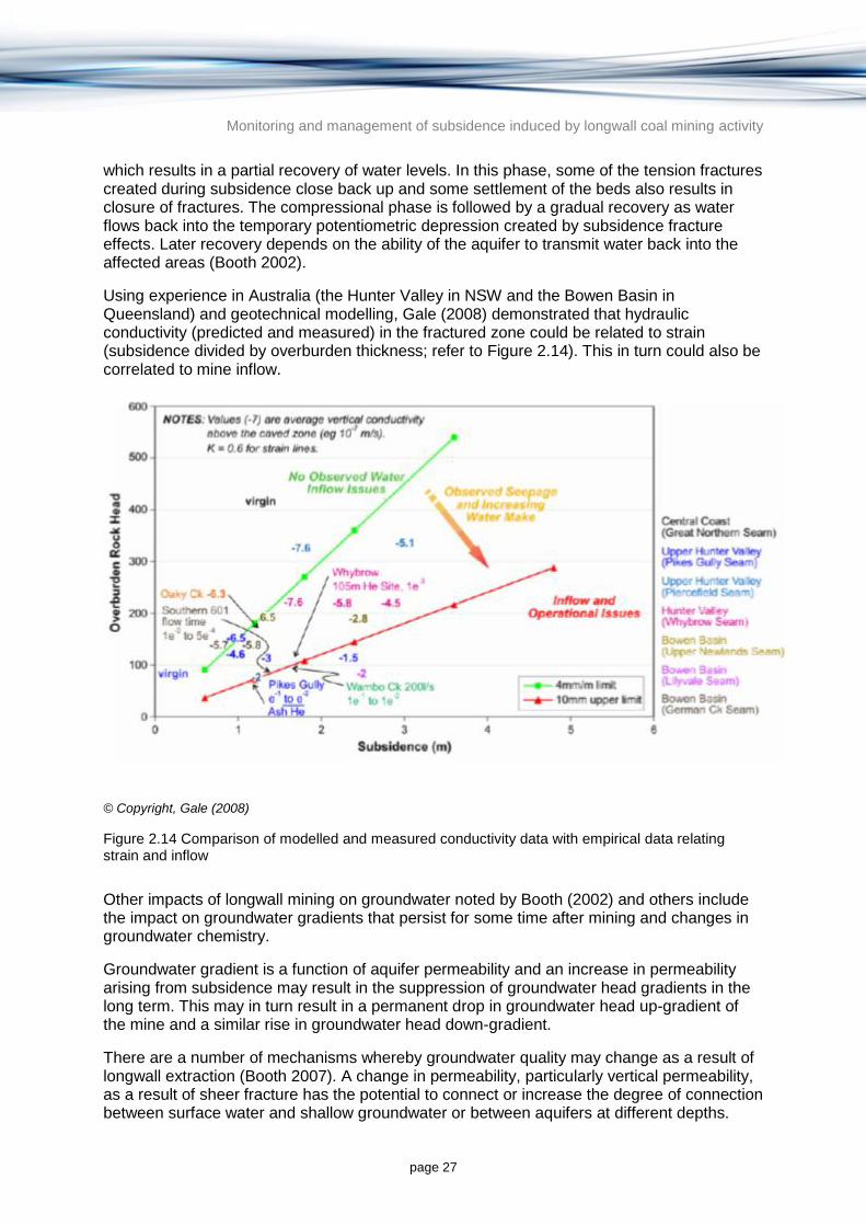
Monitoring and management of subsidence induced by longwall coal mining activity
page 27
which results in a partial recovery of water levels. In this phase, some of the tension fractures created during subsidence close back up and some settlement of the beds also results in closure of fractures. The compressional phase is followed by a gradual recovery as water flows back into the temporary potentiometric depression created by subsidence fracture effects. Later recovery depends on the ability of the aquifer to transmit water back into the affected areas (Booth 2002).
Using experience in Australia (the Hunter Valley in NSW and the Bowen Basin in Queensland) and geotechnical modelling, Gale (2008) demonstrated that hydraulic conductivity (predicted and measured) in the fractured zone could be related to strain (subsidence divided by overburden thickness; refer to Figure 2.14). This in turn could also be correlated to mine inflow.
© Copyright, Gale (2008)
Figure 2.14 Comparison of modelled and measured conductivity data with empirical data relating strain and inflow
Other impacts of longwall mining on groundwater noted by Booth (2002) and others include the impact on groundwater gradients that persist for some time after mining and changes in groundwater chemistry.
Groundwater gradient is a function of aquifer permeability and an increase in permeability arising from subsidence may result in the suppression of groundwater head gradients in the long term. This may in turn result in a permanent drop in groundwater head up-gradient of the mine and a similar rise in groundwater head down-gradient.
There are a number of mechanisms whereby groundwater quality may change as a result of longwall extraction (Booth 2007). A change in permeability, particularly vertical permeability, as a result of sheer fracture has the potential to connect or increase the degree of connection between surface water and shallow groundwater or between aquifers at different depths.

Monitoring and management of subsidence induced by longwall coal mining activity
page 28
Furthermore, where a change in permeability or storage results in an increased vertical hydraulic gradient, vertical migration of groundwater may be enhanced. A drop in head in a shallow aquifer as a result of horizontal tension combined with tension cracking at the surface is an example of a created pathway potentially allowing surface water into the subsurface (Jankowski & Knights 2010).
Groundwater mixing may result in changes in salinity and heavy metal concentrations. Other potential impacts include the introduction of surface water borne contaminants (e.g. sediment, pesticides and bacteria) to groundwater. Mixing waters of variable composition and physico-chemical properties (particularly pH and Eh) will result in changes in solute saturation leading to the dissolution of some species and precipitation of others. One of the most well documented examples of pH and Eh changes in some mines is the acidification of groundwater in the goaf as a result of the oxidation of pyritic minerals.
2.3.3 Important factors in determining the magnitude of subsidence
The simplified zones of fracturing and dilation identified by authors such as Singh and Kendorski (1981) and later by Forster and Enever (1992) describe the vertical and horizontal distribution of similar mechanical changes in overlying rock resulting from longwall mining. In turn, these mechanical changes have been found to have a direct impact on the hydraulic properties of permeability and porosity. The magnitude of impact on the mechanical properties of the overlying strata is proportional to the impact on the hydraulic properties of aquifers above the mined area. As detailed in Section 2.2.4, the changes to the rock mechanics (primarily fracturing and dilation) are controlled by the following (NCB 1966, 1975):
width of extraction
height of extraction
depth of cover
types and proximity of previous workings
interburden thicknesses
presence of pre-existing natural joints
thickness, geology, geomechanical properties of each strata layer
angle of break of each strata layer
spanning capacity of each strata layer
bulking ratios of each strata layer within the collapsed zone
presence and extent of aquitard or aquiclude zones.
2.3.4 Case studies
2.3.4.1 Bellambi West Colliery
Bellambi West Colliery, formerly South Bulli Colliery, was the first mine permitted to operate longwall panels under the Cataract Reservoir. As described in Holla and Barclay (2000), longwall mining commenced in 1993 using precautionary narrow panels (110 m) and wide chain pillars (66 m). The Bulli Seam at this location was 2.5 m thick and 320 to 430 m below the surface. Successful longwall mining of the first five panels recovered 2.5 million tonnes of coal and extended the mine life by 8 years (Singh & Jakeman 2001).
Monitoring and management of subsidence induced by longwall coal mining activity
page 29
A comprehensive program of surface subsidence and groundwater monitoring was conducted during the 3 years of panel mining. After extracting six panels the maximum subsidence had reached 173 mm, only 7 per cent of the seam thickness, and surface strains did not exceed 1 mm per m. Results of the groundwater monitoring from eight piezometers were described by Reid (1995) and Singh and Jakeman (2001), and are summarised below:
The maximum height of fracturing extended to at least 85 m above the Bulli Seam (equivalent to 34 times the seam working height, and to 325 m below the surface). At this height the lowest piezometer drained to the caved goaf and remained dry.
Piezometers set in the overlying Bulgo Sandstone experienced a drop in static water level, although they later recovered to near pre-mining levels.
Groundwater levels in the Hawkesbury Sandstone at the top of the overburden sequence were unaffected by mining almost 300 m below. It is presumed that the underlying Bald Hill Claystone, or other shale layers, remained as low permeability formations despite being deformed by subsidence movements.
On the evidence of mine pumping rates, no abnormal groundwater inflows to the workings were recorded during extraction of the six longwall panels. More water was generally pumped into the mine for dust suppression than was withdrawn. However, it is likely that low mine inflows during the caving of the first longwall panels may have been due to drainage through older mine workings (i.e. the true inflow was not measured).
Chemical analyses of mine water, performed to determine its origin (i.e. whether from direct infiltration through the overburden, from the stored waters of Cataract Reservoir, or from regional groundwater) were inconclusive.
2.3.4.2 Cataract River Gorge, Tower Colliery
Undermining the Cataract River gorge by longwall panels in the early 1990s became a public controversy, encouraged by television news footage of gas flames, dry swimming holes and conspicuous cracks in the bare sandstone stream bed. A summary report on streambed cracking, loss of stream flow and the release of hydrocarbon gases was compiled by Everett et al. (1998), while the mining and subsidence aspects are briefly described in Holla and Barclay (2000).
Longwall mining of the Bulli Seam at a depth of about 430 m below the river bed was initiated by Tower Colliery in 1988. The first five panels (1988 to 1991) were relatively narrow (110 m), with moderately wide chain pillars (40 to 48 m). Mining subsidence increased with each panel extracted, with subsidence of up to 325 mm observed over the fifth panel. This represented about 13 per cent of the seam thickness of 2.5 m, a low figure for multiple panels on the Southern Coalfield, and ground strains were generally less than 1 mm per m. No streambed losses were reported from the initial panels under the Cataract River.
The subsequent five panels (1991 to 1993), located about 1 km downstream, were widened to 155 m. The maximum subsidence increased to 475 mm by the tenth panel; 19 per cent of seam thickness. During this period cracking became noticeable in the river bed, many rock pools drained and flow ceased altogether in 1994. A task force was set up to study the problem in 1996 and investigations were commissioned by BHP (the mine owners), the NSW Department of Mineral Resources (the mining regulator) and Sydney Water Corporation (SWC). A large number of consultants’ reports were commissioned, the conclusions of which were summarised by Everett et al. (1998):

Monitoring and management of subsidence induced by longwall coal mining activity
page 30
Flow in the affected reach of the Cataract River was greatly influenced by SWC water management practices, especially the timing and amount of discharges from Broughton's Pass Weir.
The natural orthogonal joint pattern, which is common throughout the Southern Coalfield, has been overprinted by mining induced subsidence fractures that are typically about 20 mm wide at the surface and are considered to be 5 to 20 m deep (though this depth has not been proven).
The water table maintained its level above river bed level and does not appear to have been significantly affected by longwall mining 430 m below.
The Hawkesbury Sandstone consists of stacked sub-aquifers, which are poorly interconnected in their pre-mining state.
During test discharges from Broughton's Pass Weir, the river was found to have gained and lost water in different sections of the stream bed. Pools that had been considered permanent in pre-mining years were found to have emptied within one to two months after cessation of the test discharges.
Flammable gas flows (methane and ethane) issuing from stream bed cracks were measured at up to 20 litres per second and were readily ignited and visible as columns of bubbles in pools. CSIRO investigations suggest that the gas was sourced from reservoirs in the Bulgo Sandstone, rather than from the underlying Bulli coal bed. The inference from this conclusion is that there was no direct connection from the surface to the seam being mined, though a connection developed to a higher formation in the overburden.
2.3.4.3 Springvale and Angus Place Collieries, NSW
The Springvale and Angus Place Collieries are underground coal mines located near Lithgow in NSW, on the western edge of the Sydney Basin. These collieries are adjacent to one another, and are owned and operated by Centennial Coal. Coal mining at the Angus Place Colliery has been undertaken by longwall mining methods since 1979 and at Springvale Colliery since 1995.
An investigation into the effects of subsidence arising from longwall mining on overlying aquifers and groundwater dependent ecosystems (GDEs) was conducted over 4 years by CSIRO at Springvale Colliery (Guo et al., 2007). It involved monitoring 80 piezometers in 18 boreholes situated over a series of longwall panels, along with borehole extensometer monitoring and inflow measurement. Significant findings from the project were that:
Increases in rock mass permeability were detectable 250 to 275 m above the panels, depending on their width (260 and 315 m, respectively). At the actual cover depths of 300 to 380 m there was only a small increase in the permeability of near-surface aquifers that supported GDEs.
Hydrogeological changes were detectable 350 m ahead of the face (i.e. about 50 per cent in advance of changes in vertical permeability).
Modelling indicated the following approximate increases in mine inflows:
− 84 per cent when the panel width was increased from 240 to 320 m
− 41 per cent where the face height was increased from 3 to 4.5 m
− 21 per cent when production was notionally increased from 5.6 to 15 Mt per annum using the existing panel geometry.
Monitoring and management of subsidence induced by longwall coal mining activity
page 31
The impacts of mining on surface waters (Cox’s Creek and various peat swamps) are described in detail in Section 2.4.4.5.
2.3.4.4 United Kingdom (UK) experience
British interest in the effects of longwall mining on groundwater systems dates back to the 1970s, when mining under the waters of the North Sea and beneath a major Permian aquifer in northeast England raised concerns about mine safety. At least one large longwall mine at Selby in Yorkshire suffered serious flooding in 1983 when extracting coal only 80 m below a major aquifer (Dumpleton 2002). However, groundwater entry is not normally considered a potential problem, since most longwall mines in the UK operate at much greater depth (600 to 1000 m), and in less permeable rocks than is usual in the coal measures of Australia and the USA.
Whittaker et al. (1979) compared the results of monitoring groundwater changes in response to longwall extraction at a 590 m deep colliery in the East Midlands and at an unusually shallow mine (50 m) in Yorkshire. General conclusions were that:
Large increases in overlying strata permeability occur close to and immediately behind an advancing longwall face. In deep workings these changes extend laterally from the face to about 40 m behind it, and to a height of 40 m above the face. Behind the face the subsided beds close up during the compressive phase of the subsidence wave, reducing permeability once again but not back to pre-mining values.
Changes in very shallow workings can affect the surface and their onset may be detectable 60 m ahead of the face, peaking zero to 40 m behind the face. Step-like changes in packer (water injection) test results indicate that joints and bedding planes are in turn opening and closing in response to the tensile and compressive phases of the subsidence wave.
Subsidence-enhanced permeabilities were 10 to 100 times greater than their pre-mining values during the tensile phase of the subsidence wave, but diminished to 20 to 40 times the pre-mining values during the compressive phase for a shallow longwall panel.
2.3.4.5 United States (US) experience
Longwall mining became the preferred method in large mines only in the 1980s. Interest in the hydrogeological consequences of longwall and other total extraction methods arose out of their impact on rural bore water supplies in Pennsylvania, West Virginia and Illinois.
Moebs and Barton (1985) reported the results from monitoring a line of 45 m deep observation wells laid out across a longwall panel in south-western Pennsylvania. The bores were intended to simulate domestic wells tapping shallow aquifers. The site has certain similarities to the Sydney Basin, with a mining depth of 225 to 300 m and surface relief of 120 m across the test panel, although the overburden strata appear to be less stiff than the sandstones of the Southern Coalfield. The surface underwent maximum subsidence of 1.07 m but no strain values were reported. Water level readings were taken approximately weekly for six months prior to mining and for 1 year afterwards. Water samples were taken over the same period. Surface flows in permanent streams and springs were also measured. The study found:
Water levels in undermined bores fell by 3 to 7.5 m and one bore drained completely as the longwall face passed beneath it. Some of the levels recovered during the 1 year post-mining observation period.

Monitoring and management of subsidence induced by longwall coal mining activity
page 32
Water quality was only slightly affected by mining, the only consistent change being a slight increase in pH.
Wells located more than 150 m beyond the edge of the longwall panel were not affected by mining.
There was no discernible impact on the flow of surface streams crossing the panel once seasonal effects were accounted for.
2.4 Impact of longwall coal mining on surface water resources
2.4.1 Introduction
This section provides a review of current knowledge of subsidence resulting from longwall coal mining and its impacts on surface water resources. The types and ranges of impacts on surface water resources are discussed with reference to impacts on topography, geomorphology, surface hydrology and ecology. Factors that are important in determining the magnitude of the impact are discussed. A number of case studies are also presented as examples demonstrating the impact that subsidence has had across a range of catchments in Australia and overseas.
2.4.2 Types and ranges of impacts
Impacts can be divided into three broad categories which reflect the time lag between mining and impact (Petts 1987):
First order impacts refer to the immediate impacts of subsidence (also called subsidence effects) such as cracking, shearing, tilting and reopening bedding planes and joints.
Second order impacts refer to the impacts that result from subsidence effects, such as changes to hydrology from altered groundwater or surface water flow paths and water quality impacts.
Third order impacts are the result of changes to hydrology and water quality, such as streambed erosion and ecological responses.
Third order impacts can lag significantly from the first and second order impacts. Figure 2.15 shows a conceptual timeline describing the temporal differences in first, second and third order impacts.
© Copyright, NSW PAC (2009). Timing for ecological impacts could vary significantly and has not been studied in detail.
Figure 2.15 Conceptual timeline showing time lags between first, second and third order impacts

Monitoring and management of subsidence induced by longwall coal mining activity
page 33
2.4.2.1 Impacts on topography
Subsidence resulting from longwall coal mining can have a range of impacts on topography. These include cracking, the formation of steps and voids, undulation and buckling of the surface. Subsidence and changes in topography are not uniform but will vary depending on the compressive and tensile properties of the surrounding strata (Waddington & Kay 2002b; Frazier et al. 2010; MSEC 2006).
The amount of cracking can vary between a few centimetres to up to half a metre. In agricultural lands small cracks may be concealed by cultivation; however, large cracks may require filling or ripping (Frazier et al. 2010). MSEC (2006) completed a review of mining induced cracking in the vicinity of rivers and gorges in the Southern Coalfield of NSW. They noted that the majority of instances of cracking in river beds were located where longwall coal mining occurred directly beneath rivers (Figure 2.16).
Stepping of the surface may also occur along the panel as coal is removed, which in turn can create cracks. Voids may also form as a result of subsidence, and where these coincide with watercourses they can result in lowering of stream beds (Lucas et al. 2009).
Variations in the compressive and tensile properties of the strata across the panels can cause surface undulations (Frazier et al. 2010). Buckling of the surface or ‘upsidence’ may also occur (Frazier et al. 2010; Waddington & Kay 2003).
© Copyright, MSEC (2006)
Figure 2.16 Distance of observed fractures to closest edge of longwall
2.4.2.2 Impacts on geomorphology
Alterations to the physical character of landforms occur as a result of topographic impacts associated with subsidence. Changes in topography (especially gradient) have the potential to affect geomorphological processes.
The nature and scale of potential geomorphological impacts on a reach or broader catchment area are complex. Assessment of potential geomorphological impacts requires an understanding of geomorphological processes as they relate to the characteristics of the catchment. Possible geomorphological impacts associated with subsidence include:

Monitoring and management of subsidence induced by longwall coal mining activity
page 34
Cracking of rock bars or fracturing of alluvial strata altering the permeability of a stream bed. This can lead to reductions in stream flow, which in turn has potential to affect physical processes and instream habitat. Cracking in swamps has the potential to dewater and dry out these environments, reducing vegetation cover and in turn increasing the susceptibility of these areas to erosion during extreme rainfall events (NSW DoP 2008).
Lowering of channel bed and changes to channel grade. This could potentially alter channel hydraulics and patterns of sediment erosion, transportation, and deposition within an affected reach, with impacts on the character and distribution of pools and riffles and stability of channel banks (NSW DoP 2008; Lucas et al. 2009).
Depending on location and extent of subsidence on a watercourse, geomorphological impacts may extend beyond the reach and impact on the condition of the broader catchment. Upstream or downstream deepening of stream beds following subsidence may lead to incision and destabilisation of incoming tributaries, resulting in increased sediment loads to waterways (Lucas et al. 2009).
Rock falls, slumping and erosion of channel banks. Fracturing of bedrock in cliff and gorge settings can lead to rock falls (NSW DoP 2008; Total Environment Centre 2007). Slumping and erosion of channel banks may arise from cracking alluvial banks. Lowering channel beds can also affect channel bank stability (Lucas et al. 2009).
Where mining is close to, but not directly beneath, rivers the topographic and geomorphological changes associated with changes in channel gradient as a result of subsidence are small (MSEC 2006). Scouring and increased erosion is of greater concern for alluvial beds or bedrock containing soft strata, but not for hardened bedrock channels such as the Hawkesbury Sandstone that is found in the beds of major rivers in the NSW Southern Coalfield (MSEC 2006).
2.4.2.3 Impacts on hydrology
Changes in topography can result in changes in surface runoff following rainfall events, which in turn alter soil moisture across the landscape and create areas of ponding (Frazier et al. 2010). Surface and subsurface cracking can alter or create new flow paths, thus altering surface and groundwater flow. The magnitude of change in surface and subsurface flow is dependent on the extent to which subsidence changes the structure of the overlying strata (Frazier et al. 2010; MSEC 2006; Sidle et al. 2000).
MSEC (2006) reviewed the impacts of longwall coal mining to rivers in the Southern Coalfield of NSW. Subsidence related impacts on surface water primarily occur in the following ways:
diversion of surface flows into subterranean flows via fractures and joints in the bedrock, with water travelling through near-surface strata and potentially resurfacing further downstream
leakage through rock bars, where water held in ponds and pools may leak through fractures and joints in rock bars and potentially resurface further downstream
infiltration into the groundwater system, particularly where the water table is lower than the surface water level of the river
surface water flowing directly into the mine
ponding of surface water in subsided areas.

Monitoring and management of subsidence induced by longwall coal mining activity
page 35
Diversion of surface flows through subterranean flows and rock bar leakages are the main types of surface water impacts that are likely to occur as a result of subsidence induced cracking in the Southern Coalfield. These types of diversions occur naturally as a result of erosion and weathering processes and valley bulging movements, and have been observed along the Cataract, Georges and Bargo Rivers in areas unaffected by mining (MSEC 2006).
Infiltration of surface water into deeper groundwater can only occur if a conduit is established for flow through to a deeper permeable horizon. Surface water loss is generally unlikely in the longer term (MSEC 2006), especially where the water table is higher than the surface water level of the river (MSEC 2006). Research by Pells Consulting (2011) indicated that longwall mining resulted in increased downward seepage from Thirlmere Lakes, NSW leading to lower levels than would normally be expected.
Mining induced surface flow diversion into subterranean flows extends only over the area of the river bed that has experienced subsidence induced fracturing with water potentially reappearing downstream of the fractured zone. This type of water loss is illustrated conceptually in Figure 2.17. Mining induced surface flow diversion due to rock bar leakage occurs in a similar manner to diversion into subterranean flows, except that the rock bar is elevated above the rest of the river bed and the water table. The rate of leakage is dependent on the extent of horizontal fracturing in the rock bar and the water level. The rock bar leaks at a higher rate when the pool is full as there is access to all drainage paths and the water pressure is at its highest. As the pool level falls, the drainage rate reduces as the water pressure falls and access is restricted to drainage paths near the base of the rock bar. This type of flow diversion has been observed previously in the Cataract and Georges Rivers in NSW and is illustrated in Figure 2.17.
© Copyright, MSEC (2006)
Figure 2.17 Representation of surface water diversion into subterranean flow and rock bar leakage, and how rates of flows are potentially affected by subsidence induced fracturing
Experience shows that in cases of increased surface flow diversion into subterranean flows and rock bar leakage, impacts are most obvious at times of low river flow. Low flows are potentially most affected by subsidence effects as a reduction in low flows has the potential to result in increased stress for aquatic ecosystems. Figure 2.18 shows the effects of subsidence on low flow events in a surface stream in NSW (Jankowski 2008). Partial and complete loss of surface flows downstream is shown to coincide with periods of low flow.

Monitoring and management of subsidence induced by longwall coal mining activity
page 36
© Copyright, Jankowski (2008)
Figure 2.18 Effect of subsidence induced surface flow diversion showing loss of stream flow during low flow events
In extreme cases, subsidence can cause significant changes to patterns of drainage in the landscape. Subsided areas can capture and pond water leading to the formation of wetlands and lakes (Bell et al. 2000). Subsidence has also been observed to disturb and reverse the flow of rivers, causing flooding and drainage problems (Bell et al. 2000). Recent examples of expected surface ponding in subsided areas include the Carmichael Mine in the Galilee Basin (MSEC 2013) and the Eagle Downs Mine in the Bowen Basin (DERM 2010).
Redirected surface flow can interact with the various subsurface strata that it comes in contact with. There is an array of geochemical components and sediments that may be dissolved and entrained by the water passing through these strata, eventually resurfacing into drainage lines (Total Environment Centre 2007). Major ions, trace elements and metals occurring in the rock matrix can be mobilised in new fractures and bedding planes of freshly exposed rock, adding to the chemical composition of surface water (Jankowski 2008).
In surface waters overlying the Hawkesbury Sandstone aquifer, pH and bicarbonate increase due to chemical reactions involving carbonate minerals that form part of the sandstone (Jankowski et al. 2008). The presence of carbonates allows iron, manganese, zinc, strontium and barium to mobilise, significantly increasing the concentration of these elements downstream, where subsurface flow re-emerges at the ground surface. Discharge of iron and manganese-rich groundwater caused the development of thick mats of iron oxidising bacteria during low flow conditions, which have reduced habitat, clogged stream flow, reduced available food, and reduced the level of dissolved oxygen in the stream. Loss of native plants and animals may occur directly by iron toxicity, or indirectly by smothering (NSW DoP 2008; Jankowski et al. 2008). Loss of plants from swampland and waterways can increase erosion, resulting in high levels of sedimentation and further reductions in water quality (Total Environment Centre 2007; NSW DoP 2008). Gaseous emissions, such as methane and

Monitoring and management of subsidence induced by longwall coal mining activity
page 37
other natural gas components have been observed in areas affected by mining subsidence, which can also affect water quality (NSW DoP 2008).
NSW DoP (2008) state that prediction of the impact of subsidence on the water quality of watercourses is a matter of understanding a number of key parameters:
pre-mining surface flow dynamics and pre-mining water quality
proportion of surface flow likely to be lost to the subsurface during or after mining, for different per centile stream flows
amount of increased flow from near-surface aquifers or groundwater conduits to the stream and associated water quality
associated water quality impacts on the stream in terms of increased mineral concentrations, pH, oxygen, iron flocculation, and other site-specific chemical species of relevance.
2.4.2.4 Impacts on ecology
Subsidence can result in a range of impacts to the ecology of waterways, which have been summarised in a number of review publications (Waddington & Kay 2002b; NSW DoP 2008; Total Environment Centre 2007). The NSW DoP (2008) review found that longwall mining subsidence can have the following impacts on riverine features or attributes:
loss of surface flows or reduction of water levels (increased frequency, duration and magnitude of drying of aquatic habitats)
loss of aquatic or instream habitats (complete drying of river pools, instream macrophyte beds and wetlands has occurred which may in some cases be irreversible)
loss of longitudinal connectivity (less connectivity between pools and riffles may reduce migration opportunities)
changes to water quality (increased iron oxides, manganese, sulphides and electrical conductivity (EC), and lower dissolved oxygen)
reduced diversity of instream habitat due to growth of iron oxidising bacteria which can also be seen as a rusty coloured mass in the water
release of gas into the water column (oxidation of gas may lead to death of riparian vegetation and instream fauna).
Changes to flow and water quality has the potential to alter ecological processes and disrupt biological linkages (i.e. longitudinal connectivity, water availability). In these situations damage to aquatic ecology can be widespread. Upstream habitats may no longer be accessible and movement of animals for feeding and breeding purposes may be restricted or halted completely (Waddington & Kay 2002b; NSW DoP 2008).
Swamps were identified by NSW DoP (2008) as being potentially vulnerable to subsidence. Differences in swamp geomorphology, geometries and locations are likely to affect the extent to which there are adverse impacts. Swamps overlying bedrock are expected to respond in a similar way to streams traversing bedrock. Fracturing of rock surfaces would be anticipated beneath these swamps, which may lead to drainage of water from the swamp into the fractured rock. It is possible that swamp deposits may dry out and increase susceptibility to erosion by extreme rainfall and runoff events (NSW DoP 2008). It can also be expected that subsidence induced changes in slopes or stepping of the surface (creation of knickpoints)

Monitoring and management of subsidence induced by longwall coal mining activity
page 38
may also increase the potential for rapid incision and drainage of swamp areas (Total Environment Centre 2007).
The Total Environment Centre (2007) review cited a number of examples where subsidence induced by longwall mining has affected swamps in NSW:
Wongawilli Creek suffered from subsidence induced cracking. Upland swamps were drained and changes to water quality were observed downstream.
Flat Rock Swamp is believed to be the main source of water recharge for Waratah Rivulet and is thought to have been tilted and drained.
Long Swamp at the source of Cox’s River is drying and decreases in surface flows have been recorded, probably as a result of longwall mining at the top of the catchment.
Newnes Plateau Swamps are located above longwall panels and have reportedly been damaged.
2.4.3 Important factors in determining the magnitude of impact
The impact of longwall mining on surface water resources is highly variable and depends on the local geology and soil types present above the mining area (Waddington & Kay 2002b). A number of authors have highlighted that subsidence impacts are greatest when longwall panels are mined directly under surface waters, and that impacts are comparatively less when mining occurs at some distance away from the watercourse (Waddington & Kay 2002b; MSEC 2006).
There are many cases to demonstrate that longwall mining beneath creeks and rivers will cause cracking in the bedrock and leakage of water from the creek and river beds into underlying strata (Waddington & Kay 2002b; Total Environment Centre 2007). Subsidence induced movements will tend to increase the permeability of surface strata, which may affect the quantity and quality of surface water (Waddington & Kay 2002b; Total Environment Centre 2007). Water quality impacts will vary depending on the chemical composition of the cracked strata and chemical reactions that occur during water-rock interactions (Jankowski et al. 2008).
Alluvial rivers appear to respond differently to subsidence than rivers on bedrock. With the absence of bedrock controls, cracking is less pronounced; however, it is still possible that the quantity and quality of surface flows may be affected as a result of changes to the permeability of strata. Alluvial rivers can be expected to be more affected by changes in stream bed level and grade than by the drainage observed in bedrock controlled systems. The extent to which subsidence affects the stability of the channel and broader drainage network is dependent on the degree to which subsidence alters channel hydraulics and patterns of sediment erosion, transportation, and deposition. Instabilities at the site of subsidence can progress upstream and downstream through channel deepening processes.
Swamps vary in their sensitivity to subsidence based on differences in geomorphology, geometries and location in the landscape. Bedrock controlled swamps, similar to bedrock rivers, are susceptible to cracking which can lower the water table. Swamps in alluvial settings may be more susceptible to subsidence induced changes in slope, and the formation of knickpoints that increase the potential for rapid erosional incision and drainage (Total Environment Centre 2007).

Monitoring and management of subsidence induced by longwall coal mining activity
page 39
2.4.4 Subsidence surface water impact case studies
2.4.4.1 Waratah Rivulet, NSW
Waratah Rivulet is located in the Woronora catchment upstream of Woronora Dam in NSW. The Healthy Rivers Commission described the condition of the Woronora catchment upstream of the dam as largely pristine in 2009. Underground operations have taken place directly underneath Waratah Rivulet (Total Environment Centre 2007).
In 2006 serious damage to the Waratah Rivulet was reported by the Sydney Catchment Authority (SCA). Inspections were carried out along the length of the rivulet overlying the longwall panels. The rivulet had ceased to flow for much of its length. Cracking of the sandstone bed was noted and at one location it was reported that water levels had dropped by approximately 3 m. Anecdotal evidence suggested that the rivulet ceased to flow in areas never previously known to stop flowing (Total Environment Centre 2007).
Titling of the watercourse to the east was documented and iron oxide pollution was observed. Flat Rock Swamp is believed to be a main source of water for the Waratah Rivulet and it is considered highly likely that the swamp was drained and tilted (Total Environment Centre, 2007). Further detailed information on the impacts of subsidence on two rock bars on the Waratah Rivulet was documented by Galvin (2005).
2.4.4.2 Cataract River, NSW
The Cataract River is a tributary of the Upper Nepean River in NSW. Nine longwall panels were mined directly under the Lower Cataract River from 1988 to 2000. Damage to the river was reported by local residents in 1994. Surface water had drained from the river through hundreds of cracks in the river bed, and fish kills were reported. Methane began to vent from the river bed from 1996 (Total Environment Centre 2007). The dam wall at Broughton's Pass Weir was cracked in four places leading to leakage across its face. A pump house adjoining the weir was also damaged. The Nepean tunnel and the upper canal were cracked but the extent of water loss was not established (Total Environment Centre 2007). In the 2003/04 financial year the SCA spent $5.58 million on the upper canal; $2.23 million of which was for ‘extensive mining related preventative work’ (Sydney Morning Herald 2005).
Cracking has affected the quantity and quality of surface water in the Cataract River. The NSW Department of Land and Water Conservation estimated that the Cataract River had lost 50 per cent of its flow to bedrock cracks (Total Environment Centre 2007). Total Environment Centre (2007) note that environmental flow releases of 1.7 ML per day are no longer sufficient to keep the river flowing or to maintain acceptable water quality. Further detailed information on the impacts of subsidence on the Cataract River is documented in DIPNR (2002).
2.4.4.3 Isaac River, Qld
The Isaac River is a major tributary of the Fitzroy River in the Bowen Basin in central Queensland. Lucas et al. (2009) undertook a study to assess the potential cumulative impacts of mining development, and in particular longwall mining related subsidence, on the Isaac River over a river length of approximately 100 km near Moranbah. Subsidence values of 1.5 to 3 m have been observed following longwall mining. Geomorphological impacts expected on alluvial channels are illustrated in Figure 2.19, with similarities likened to the geomorphic response that follows sediment extraction programs.
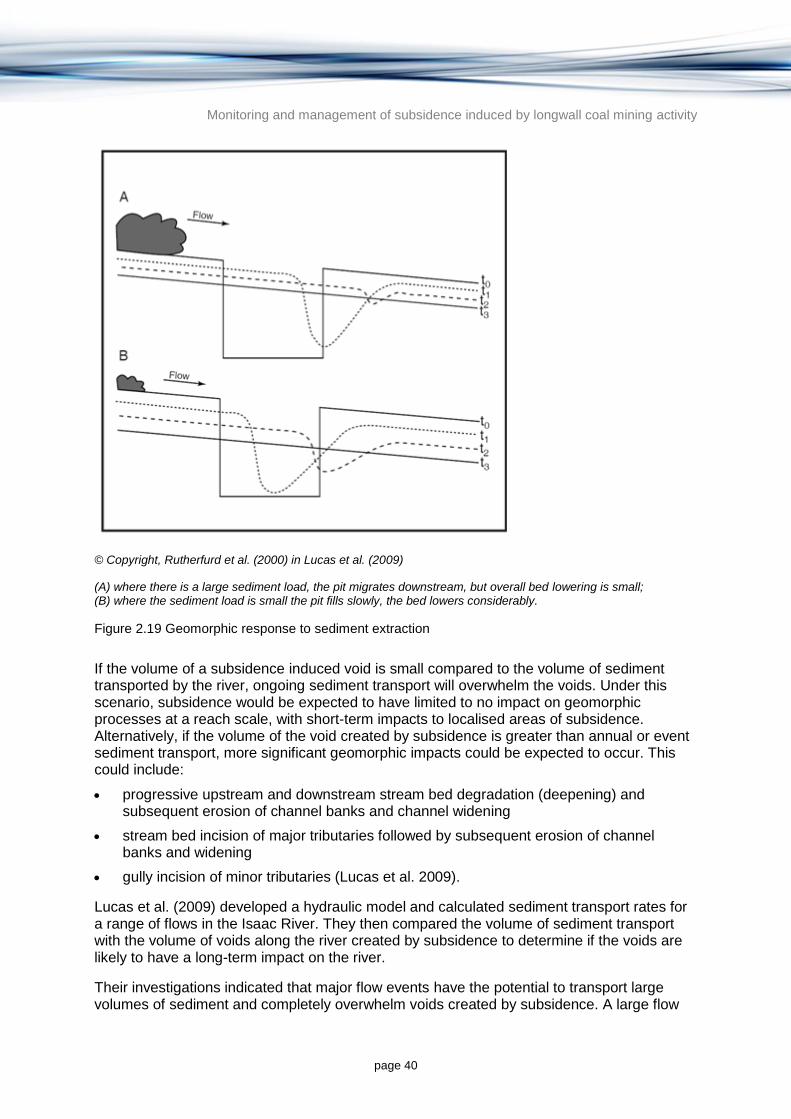
Monitoring and management of subsidence induced by longwall coal mining activity
page 40
© Copyright, Rutherfurd et al. (2000) in Lucas et al. (2009)
(A) where there is a large sediment load, the pit migrates downstream, but overall bed lowering is small; (B) where the sediment load is small the pit fills slowly, the bed lowers considerably.
Figure 2.19 Geomorphic response to sediment extraction
If the volume of a subsidence induced void is small compared to the volume of sediment transported by the river, ongoing sediment transport will overwhelm the voids. Under this scenario, subsidence would be expected to have limited to no impact on geomorphic processes at a reach scale, with short-term impacts to localised areas of subsidence. Alternatively, if the volume of the void created by subsidence is greater than annual or event sediment transport, more significant geomorphic impacts could be expected to occur. This could include:
progressive upstream and downstream stream bed degradation (deepening) and subsequent erosion of channel banks and channel widening
stream bed incision of major tributaries followed by subsequent erosion of channel banks and widening
gully incision of minor tributaries (Lucas et al. 2009).
Lucas et al. (2009) developed a hydraulic model and calculated sediment transport rates for a range of flows in the Isaac River. They then compared the volume of sediment transport with the volume of voids along the river created by subsidence to determine if the voids are likely to have a long-term impact on the river.
Their investigations indicated that major flow events have the potential to transport large volumes of sediment and completely overwhelm voids created by subsidence. A large flow

Monitoring and management of subsidence induced by longwall coal mining activity
page 41
event following subsidence may result in immediate infilling of the void, and limited to no impact on stream processes, with the exception of some localised upstream and downstream deepening. However, an extended period of low flow may take many decades to infill a large void and could result in significant impacts on the stream system (Lucas et al. 2009).
Lucas et al. (2009) also indicated that it would generally be expected to take a number of decades before the voids could be expected to be refilled with sediment, and that voids are expected to have significant geomorphic impacts on the river extending upstream and downstream. Overall, bed deepening of 2 m could occur in some of the reaches, which could cause incision and destabilisation of tributaries. Waterway management interventions could assist in mitigating these impacts (Lucas et al. 2009).
2.4.4.4 Burnout Creek, Utah
Short-term geomorphic and hydrologic effects of subsidence induced by longwall mining under Burnout Creek, Utah were evaluated by Sidle et al. (2000). Channel features were surveyed along entire lengths of streams in longwall mining impacted areas, as well as streams outside of mining areas. Channel units were mapped as cascades, riffles, runs, glides and pools.
Documented cross-sections were surveyed at various points along the creeks in locations corresponding to zones of predicted maximum tension or compression. Longitudinal profiles were recorded in the channel thalweg at 10 m intervals and at other channel features including significant steps in the channel, and resurveyed each year. Stream bed sediments were sampled and analysed and water flows were measured.
During the year after longwall mining 0.3 to 1.5 m of subsidence was measured near affected reaches. Subsidence did not affect the base flow at the mouth of the creek over the 3 year period of monitoring. Some of the channel changes measured were potentially negative (e.g. increases in cascades in some reaches) and some could be considered positive (e.g. increase in pool numbers and volumes). The authors concluded that it was difficult to address any long-term channel trends from a 3 year investigation and that many of the impacts of subsidence appeared to be short-lived.
2.4.4.5 Cox's River, NSW
Centennial Coal’s longwall mining operations at the Angus Place and Springvale Collieries near Lithgow, NSW were found to have affected a number of swamps in the Cox’s River catchment. Narrow Swamp, East Wolgan Swamp and Junction Swamp (DSEWPaC 2012) are all listed as ‘Temperate Highland Peat Swamps on Sandstone’ under the EPBC Act 1999. Impacts to swamps included peat erosion, vegetation die-back, weed invasion and changes in vegetation composition in the swamps. As a result of these impacts, Centennial Coal entered into an Enforceable Undertaking with Australian National University (ANU) and provided $1.45 million towards a research program investigating the environmental impacts of longwall coal mining in the area (DSEWPaC 2012).
The East Wolgan swamp was severely affected by subsidence, with cracking in the sandstone beneath the swamp causing surface water flows to be redirected underground and water levels in the swamp to drain through cracks. This resulted in drying the swamp sediments, erosion of the peat and formation of peat balls that washed downstream and left a large slump hole in the swamp. Cracking of the sandstone beneath East Wolgan Swamp was first reported by Centennial Coal in 2009 and subsequently reported on in various subsidence management status reports (Centennial Coal 2013). Centennial Coal claimed the

Monitoring and management of subsidence induced by longwall coal mining activity
page 42
cracks were minor and were ‘self-healing’; however, conservation groups observed that large volumes of surface water (and mine waste water) were draining through the cracks, and resulting peat erosion was significant (Muir 2010).
Drying of the swamps causes changes in vegetation composition, with the loss of moisture-dependent swamp species and a transition towards more woody species such as eucalypts within the swamp. For example, eucalypts have been observed encroaching on the swamp area in the headwaters of Kangaroo Creek and in Junction Swamp (Muir 2010).
Cliff falls caused by longwall mining between June 1985 and October 1988 at the Angus Place Colliery has been monitored by the NSW Department of Mineral Resources. Fifty-five cliff falls were recorded, damaging hanging swamps (Total Environment Centre 2007) and aboriginal art sites in the area (Muir 2010).
Cracking the sandstone beneath the swamps and draining water impairs the ability of the swamp to regulate downstream flows. Under normal conditions the swamp slowly releases water downstream, maintaining both water quality and persistence of downstream flows. Cracks in the sandstone beneath Narrow Swamp, Junction Swamp at the headwaters of Kangaroo Creek (Muir 2010) and beneath Long Swamp in the Cox’s River headwaters (Total Environment Centre 2007) are thought to have reduced streamflow downstream of the swamps.
Redirecting surface water flows into the subsurface via sandstone cracks can also have adverse effects on water quality. Although there is little evidence to support the re-emergence of water further downstream of the swamps, it is thought to have occurred at East Wolgan Swamp, where the re-emergent water was of poor quality and resulted in orange staining of the Wolgan River (Muir 2010). Water quality impacts are caused by the dissolution of minerals (e.g. marcasite and siderite) in the sandstone which release iron and manganese into the water (Krogh 2007).
Potentially the most obvious impacts of longwall mining on the swamps above the Springvale and Angus Place Collieries were the impacts of mine waste water discharge on swamp vegetation. High salinity waste water was discharged to the headwaters of the swamps for approximately 10 years and caused significant die-back of teatree and grevillea at East Wolgan Swamp (Muir 2010). Waste water discharge no longer occurs above the swamps; however, Centennial Coal retains emergency discharge licenses for those locations.
2.4.4.6 Thirlmere Lakes, NSW
Tahmoor Colliery is an underground coal mining operation situated in the Southern highlands Region of NSW, just south of the Tahmoor Township and approximately 75 km southwest of Sydney. It targets the Bulli coal seam and mining began in 1979. The primary method of coal extraction until 1987 was bord and pillar mining, after which longwall mining was introduced. The mine currently has development approvals to produce up to three million tonnes Run of Mine (ROM) coal per annum (Tahmoor Coal 2013).
The mine is located adjacent to Thirlmere Lakes, which are described as a unique wetland believed to be 15 million years old. The Lakes are within Thirlmere Lakes National Park, part of the Greater Blue Mountains World Heritage Area. Over the last 10 years, the water levels in Thirlmere Lakes have declined and members of the community have expressed concern. The NSW Government announced an independent inquiry in 2011 into the reductions in the level of Thirlmere Lakes, which delivered a final report in August 2012 (ITLIC 2012). The inquiry found that the lakes have fluctuated between dry and full conditions over recorded
Monitoring and management of subsidence induced by longwall coal mining activity
page 43
history and that climate change is ‘undoubtedly responsible’ for the majority of the changes in lake level that have been experienced over the last 40 years. The inquiry found that there is no direct evidence that mining and associated subsidence has breached geological containment structures beneath the lakes. However, it concluded that there is substantive evidence of the steepening of the hydraulic groundwater gradients and lowering of the groundwater table towards the east of the lakes. The inquiry further concluded that there is some evidence to suggest that mining has contributed to changes in water table and groundwater gradients but it is not possible to distinguish changes due to mining from changes due to extraction of groundwater from bores and climate change (Riley et al. 2012).
Pells Consulting (2011) considered the available information on groundwater, geology and mining to provide three hypotheses to help explain lake level observations:
1. that the lakes have dried due to recent drought
2. that longwall mining at the neighbouring Tahmoor Colliery has resulted in increased downward seepage from the lakes
3. erosion of a palaeochannel beneath Lake Nerrigorang has allowed greater seepage and leakage to groundwater from the lake.
Pells Consulting (2012) considered more recent climate and lake level observations and concluded that recent water levels in Lake Nerrigorang are atypical of its historic behaviour, which points to factors other than climate for its current dry condition.
2.5 Subsidence mitigation and remediation methods
2.5.1 Background
This section discusses measures for preventing, minimising and repairing surface and near-surface subsidence damage caused by coal mining, with particular reference to longwall mining projects in Queensland. Although some generalisations can be made, subsidence mitigation is a site-specific activity that is greatly influenced by the seam geometry, overburden geology, surface soils and topography, current land use and mining technology (McNally et al. 1996a). Other factors to be borne in mind are that:
mitigation and rehabilitation measures are only economically feasible for relatively small portions of the subsided land, typically only a few hectares above a longwall panel that might occupy 50 hectares or more
many of the subsidence mitigation measures reported in the literature are only experimental, or have rarely been applied. This is especially true of some overseas techniques that are employed only in areas with nearby or overlying human settlements
some European and Chinese subsidence control measures are (or were, in the case of the UK) heavily subsidised to protect the local coal mining industry. Most are expensive, especially in terms of coal left unmined, and could prove to be uneconomic in the export oriented Australian coal industry.
For the purposes of this report, the term ‘mitigation measures’ is taken to include all subsurface techniques that can be applied at mine level or in the overburden to minimise subsidence effects, while ‘remediation techniques’ are those implemented to assets (such as buildings or landforms) at or near the surface. While mitigation measures are implemented in advance of mining, remediation may occur just before, during or after the longwall face passes beneath a particular structure.
Monitoring and management of subsidence induced by longwall coal mining activity
page 44
2.5.2 Subsidence management plans
2.5.2.1 NSW practice
Pre-mining Subsidence Management Plans (SMPs) have been a compulsory element of the underground coal mining approval process in NSW since 2004, in accordance with the Mining Act 1992 (Mills 2009). Other aspects of subsidence impacts are controlled by the Coal Mines Regulation Act 1982 (dangers to underground miners from flooding of active workings); the Dams Safety Act 1978 (mining under stored waters); and the Mine Subsidence Compensation Act 1961 (compensation for subsidence related surface damage).
Prior to July 2014, proponents were required to develop a SMP which contained information on the project location, its surface features, the mining method and area affected, site geology and hydrogeology. The mining proponent was required to present ‘proposals to prevent, mitigate or rehabilitate subsidence impacts’, along with monitoring and contingency plans. Typically a SMP would cover several longwall panels and 3 to 5 years of forward production. All surface and subsurface water features that might be affected by the mining proposal were identified. From 1st July 2014, the former SMP process was replaced by a consolidated Extraction Plan process. This process provides for the joint regulation3 of mine subsidence under a single Extraction Plan (NSW DTIRE 2015). Much of the requirements of the previous SMP process are required in the new Extraction Plan.
In NSW the onus is on the mining proponent (via an SMP) to demonstrate that a particular asset will be protected. This usually entails a significant program of geological investigation, rock mechanical testing, numerical modelling and survey monitoring. Conservative panel dimensions are chosen initially, such that the risk of subsidence damage is low. If the results from the initial panels are satisfactory, some relaxation may be allowed in subsequent panels, but it is up to the mining company to present a case before approval may be granted (Mills 2009).
2.5.2.2 Queensland practice
Under the Mineral Resources Act 1989 (Qld) an applicant for an underground mining project is required to demonstrate that subsidence impacts have been considered and that appropriate action will be taken to mitigate and manage impacts. This information must be submitted in publicly accessible documents at the time that the development application is lodged. In addition, a proponent must submit a mine management plan once the mining licence is granted, which needs to address both subsidence mitigation and remediation options. There is no formal subsidence management plan required as is the case in NSW but rather subsidence management is incorporated into the environmental impact statement (EIS) or environmental management plan (EMP) prior to a mining licence being granted and in the mine management plan once the mining licence is granted.
The Queensland Department of Natural Resources and Mines in recent years has focussed on problems of pothole subsidence over shallow abandoned bord and pillar workings in the City of Ipswich, which has caused the collapse of many houses (Shen et al. 2010).
2.5.3 General mitigation measures
3 Jointly managed by the Department of Planning & Environment, and Division of Resources & Energy within
NSW Trade & Investment.

Monitoring and management of subsidence induced by longwall coal mining activity
page 45
The damaging effects of subsidence are primarily mitigated by modifying mine layouts to protect specific surface structures and water resource assets. The usual aim is to minimise the critical subsidence parameters—tensile strain and tilt—rather than to reduce vertical movement. Where protection of surface water and aquifers is the primary concern, the aim is to limit vertical crack propagation. Common subsidence mitigation measures are summarised below.
2.5.3.1 Positioning
A particular surface structure or landscape feature may be protected by designing or aligning extraction panels, such that a solid pillar of coal remains below them. This was accomplished by old-time bord and pillar working where the mining layout is flexible, but is less easily accommodated with longwall mining, where the panels are very large (typically 200 to 300 m wide by 2 to 3 km long, although these dimensions can be reduced to some extent (Mitchell 2009) and layout is inflexibly constrained by adjacent panels.
Some care is required to ensure that the protected feature lies outside the area within the AoD where tensile strains remain small. In the Sydney Basin the AoD is typically about 26.5 degrees (Holla & Barclay 2000), which means that the peripheral area of high tilt and large tensile strains around a longwall panel has a width about half the mining depth. A buffer zone should be at least 100 m wide where the mine workings are at 200 m depth. A more conservative assumption of an AoD of 45 degrees would result in a peripheral buffer zone equal to the depth of mining, 200 m in this example.
A more feasible form of mitigation is to ensure that the panel is laid out so that its centre line passes beneath the object being protected where the object will experience only the transient single passage of the subsidence wave. Conversely, structures located along panel edges are most at risk, since tensile strains may remain active for about 1 year, until the strain is relieved by mining the next panel in the series (NCB 1975).
2.5.3.2 Partial extraction
The most common longwall subsidence mitigation measure used in Australia is panel and pillar mining, otherwise known as shortwall or miniwall mining. Narrow faces are driven between wide pillars with the aim of keeping the panel width subcritical to ensure little or no caving and roof fracturing occurs, and surface movement is small. Prior to 1973 the following general subsidence rules prevailed in NSW (Mills 2009):
Where no subsidence at all was allowed, only bord and pillar ‘first working’ was permitted. Mine roadways (bords or tunnels) were driven in a grid pattern and pillars were outlined but not taken. The mine roof strata remained fully supported but only about 30 per cent of the available coal could be mined.
Where subsidence of up to 150 mm was tolerable, some pillars could be extracted within defined rules. However, total extraction methods such as longwall mining were forbidden.
For subsidence in the range 150 to 600 mm, panel and pillar methods (Kapp 1985) could be adopted, but the panel width (which equals longwall face length) had to be less than one third of the mining depth. Inter-panel pillars also had to be wider than 0.16 times the depth and at least 10 times the worked height (plus face height) of the seam. Thus, an inter-panel pillar at depth 200 m would need to be at least 32 m wide.
Longwall or other total extraction mining methods would only be approved where surface subsidence of more than 600 mm was acceptable. By comparison, typical vertical
Monitoring and management of subsidence induced by longwall coal mining activity
page 46
movements in parts of the Sydney Basin where subsidence is not otherwise restricted may be 1 to1.5 m (Holla & Barclay 2000).
In the 1980s it was found that under strong and thick roof strata (e.g. a 20 to 30 m thick sandstone or conglomerate bed) the panel width could gradually be increased to perhaps 0.7 times the depth, with careful monitoring. In the Newcastle Coalfield where such conditions prevail this can mean a panel about 140 m wide instead of only 60 m (Creech 1995), which may yield enhanced production.
Partial extraction can also be carried out using modern mechanised bord and pillar techniques, by which sufficient pillars are left to fully support the roof strata. This should not be seen as a general replacement for longwall mining, since the seam recovery by area is in the range of only 35 to 70 per cent. There are other cost penalties relative to longwall extraction, such as the need to maintain two sets of mining equipment (Mitchell 2009).
2.5.3.3 Backfilling
Backfilling or stowing of mined-out seam voids to prevent subsidence has been carried out at many building sites in the Newcastle Coalfield and around Ipswich over the past 40 years, but all of these cases were in abandoned shallow workings rather than in active longwall mines. These were expensive and localised measures needed to protect buildings and roads, and the backfill material in both cities was locally abundant power station fly ash.
Beginning with mines at Cessnock, NSW (McNally 1998), the use of backfill such as fly ash, sand and coal washery reject in active mines has been investigated intermittently since the 1950s, but never actually implemented (e.g. ACARP 2010). Although backfill stowing has so far been rejected for Australian mines on the grounds of cost, it is commonly used for subsidence mitigation when mining beneath urban areas in China and India (Lokhande 2005).
Chinese experience suggests that vertical movement can be reduced to 10 to 30 per cent of the seam thickness with backfilling (Guo et al. 2009), compared to 50 to 60 per cent in the Sydney Basin. More importantly, damaging surface strains are reduced proportionately. The favoured backfill material in China is a low moisture content viscous paste (76 to 85 per cent solids) made up of fly ash and fine coal washery reject, which is extruded and compacted behind the longwall face supports in a continuous operation. The backfill primarily supports the seam roof but has a secondary role providing lateral support for pillars. Despite its use in China and India in this manner, questions remain over the long-term leaching of heavy metals concentrated by combustion in fly ash and their potential impact on groundwater resources.
2.5.3.4 Bed separation grouting
Bed separation grouting involves injecting grout from surface boreholes into bedding plane cracks that open up ahead of an advancing longwall face, and which may individually be up to 200 to 300 mm high and collectively 1 m or more thick. Subsidence could in theory be reduced by half if all the larger cracks are successfully filled (Shen et al. 2010).
The injected grout is a mixture of fly ash and fine coal washery reject, similar to but wetter than that which is used in paste backfilling. It functions by reducing the amount of vertical movement in the overburden, while at the same time stiffening these strata. In addition, bed separation grouting, like stowing, provides a means for disposing of mining and power generation wastes. Feasibility studies have been carried out at West Cliff and Mandalong Collieries in the Sydney Basin, and at Moranbah North in the Bowen Basin (Shen et al. 2010).

Monitoring and management of subsidence induced by longwall coal mining activity
page 47
Favourable conditions for this technique include a mining depth of at least 200 m, grouting horizons (bed separations) more than 50 m above the seam, borehole locations 100 to 200 m ahead of the face, and the availability of suitable backfill materials (ACARP 2010).
2.5.4 Mitigation measures for surface water and groundwater resources
Entry of surface water or groundwater into active mine workings has been a matter of safety concern in NSW since the 1880s, following a number of fatal flooding incidents (Atkinson 1902). Rules since developed by the NSW Coal Inspectorate stipulated that longwall panels shall have (ACARP 2000):
minimum rock overburden cover of 180 m (beneath tidal waters) or 120 m (beneath stored waters or aquifers)
maximum tensile strain 7.5 mm/m developed at the rockhead (i.e. at the top of the overburden or at the base of the aquifer) which is equivalent to one 75 mm wide bedding separation per 10 m vertical interval.
Similar empirical subsidence mitigation rules were adopted by overseas mine regulatory authorities and have been summarised in ACARP (2000). This general approach provides a useful starting point for devising mitigation strategies, but has largely been superseded by numerical modelling, based on monitoring and rock mechanics studies and most importantly on experience gained from previous panels. In addition, protection of surface water and groundwater must take account of the overburden geology (McNally et al. 1996b), including such factors as the:
presence (or absence) of major faults, lineaments (joint clusters) or dykes, which may act as conduits downwards from water bodies
presence of thick and strong bridging strata (massive sandstone or conglomerate, dolerite sills, basalt flows), which on the one hand may limit upward crack propagation but may also act as aquifers themselves
thickness and properties of confining beds, such as shale, within the overburden. The most important property of these beds is their capacity to deform plastically and seal off vertical water transmission
thickness and composition of surface soils and alluvium, especially their self-sealing capacity above rock head.
2.5.4.1 Limiting fracture propagation
Over the past 40 years, much research effort has been applied to determining the maximum height of fracturing above Australian longwalls, with the aim of protecting surface water and groundwater from the effects of subsidence induced tensile strains (e.g. ACARP 2000; Guo et al. 2007). The height of fracturing, as determined by borehole extensometers, ranges from about 9 to 43 times the mined thickness of the seam (ACARP 2000; ACARP 2007).
As with vertical movement, fracture propagation can be limited by the adoption of narrow longwall faces (panel and pillar mining), or by reducing the worked seam thickness. In NSW subsidence fracturing generally extends upwards for 20 to 30 times the worked thickness, hence 50 times is used as a conservative upper value (Mills 2009). Mills (2009) also suggested that faces be restricted to less than 1.6 times the panel width. For example, a typical 2.4 m thick seam would require at least 120 m of overburden cover to protect overlying water bodies; this in turn would dictate a maximum panel width of 75 m. Increasing

Monitoring and management of subsidence induced by longwall coal mining activity
page 48
the extracted seam height to 3 m would require 150 m of cover but the maximum panel width could increase to 94 m due to the greater thickness of overburden.
2.5.5 Remediation measures for surface structures
Remediation is taken to comprise those measures taken in building design or temporary shoring ahead of undermining, to counteract the damaging effects of longwall mining induced subsidence. It is again worth emphasising that the measures taken should be specific to the structure being protected, and to the geological and mining factors prevailing. Three key issues are: to build flexibility in to the structural design; to limit dimensions (length especially, but also height); and to ‘decouple’, where possible, ground strains from building strains. The latter might involve (e.g.) isolating a raft foundation from its subgrade by means of a polyvinyl chloride (PVC) plastic sheet or a sand layer. It could also mean having the ability to lift and re-level a bridge deck or section of railway track. Willey (1993) described monitored house foundation behaviour when undermined at Newvale, NSW, and the superiority of reinforced cellular rafts over strip footings in these circumstances.
Other remedial measures against subsidence damage are summarised by Whittaker and Reddish (1989) and Holla and Barclay (2000) including:
modular building construction with flexible joints at close spacings and physical separation of modules
maximum use of reinforced raft foundations, with slippery underlays and jacking points for re-levelling after the passage of a subsidence wave
trenching around buildings and backfilling with flexible sand or gravel, to absorb ground strains
temporarily lifting light buildings off their foundations and replacing them on new foundations after undermining
limitations on the width of spans and the use of masonry (stone especially, but also brick and precast concrete panels)
limitations on the provision of rigid fences and on the extent of paved areas, with special requirements for swimming pools
underpinning of sensitive structures such as old masonry buildings with reinforced concrete pads and provision for re-levelling these
temporarily supporting and buttressing bridges and other large structures during passage of the subsidence wave
the use of flexible road pavements (asphalt) in preference to rigid (concrete) pavements, with flexible slots cut at regular intervals to absorb strains
inserting flexible joints in buried pipes and making provision for exhuming and re-grading existing services (especially low gradient gravity sewer lines)
providing reinforced cruciform footings for electricity transmission towers.
Appleyard (2001) emphasises remedial provisions that can be built into the design of domestic structures likely to be undermined. Indeed these are compulsory in declared mine subsidence districts in NSW, where free insurance is provided by the NSW Mine Subsidence Board.
2.5.6 Remediation measures for surface and ground waters
Monitoring and management of subsidence induced by longwall coal mining activity
page 49
2.5.6.1 Channel repairs
A number of measures are available for rehabilitating waterways affected by subsidence induced channel cracking and erosion. However, Dawkins (2003) concedes that in many cases these measures are ineffective or cause excessive surface damage through the entry of heavy equipment for earthworks and drilling. Available measures include:
sealing rock floors with clay or injected grout, or encouraging natural crack blockage by bed load sediments (Dawkins 2003)
controlling bank erosion by re-grading slopes, encouraging vegetation regrowth and fencing out livestock (Dawkins 2003)
vegetation stabilisation of denuded areas: revegetation of creek banks and alluvial terraces to mimic the local vegetated sections of the creek by using grasses, indigenous trees and shrubs (GeoTerra 2010)
installing weirs constructed from natural materials to arrest headward erosion (Dawkins 2003)
strain relief slotting to protect a prominent waterhole rock bar has been reported on one occasion (Mills 2004).
Weaknesses of the rehabilitation approach identified by the NSW Department of Planning (NSW DoP 2008) include:
lack of baseline data against which rehabilitation outcomes should be measured
lack of agreed completion criteria for the measurement of rehabilitation outcomes
lack of research and experience in applied rehabilitation techniques for these types of mining related impacts
lack of research comparing the outcomes of active remedial interventions with natural processes of remediation
difficulties in accessing affected sites due to remoteness, terrain and/or high water levels
lifespan of rehabilitation products such as grout
environmental impacts of remediation and related access in pristine natural areas (particularly restricted access water catchments)
lack of an approvals processes for remediation activities.
Natural processes have also been assessed by NSW DoP (2008) for the potential to deal with subsidence impacts to surface water streams. Two examples were given of natural streams with different natural recovery rates based on the nature of the stream bed, banks and substrate:
The Nepean River is heavily regulated by weirs and can be considered as a long, shallow, generally low stream energy impoundment in the area where mining has and will take place. Rate of flow is therefore interrupted and the river contains a substantial and semi-constant water column and a significant bed load of fine sediment and decomposing vegetation. Cracking of the stream bed beneath this sediment load is unlikely to cause long-term consequences, and the short-term impact of gas release generally dissipates over a number of months.
The Waratah Rivulet is a high energy stream environment with a low natural sediment load which has been impacted by upsidence, rock bar cracking and pool drainage, and
Monitoring and management of subsidence induced by longwall coal mining activity
page 50
therefore may be expected to show a much slower rate of natural remediation (NSW DoP 2008).
Evidence of self-healing of cracking in beds through moss and lichen sealing and colonisation by other flora and fauna has been observed by NSW DoP (2008). No evaluation of the effectiveness of this method of rehabilitation is possible at present due to the lack of data and control sites.
2.5.6.2 Aquifer repairs
The options available for repairing subsidence damage to shallow aquifers are limited to localised grouting, while there are no viable options for deeper aquifers (Dawkins 2003). For aquifers, subsidence mitigation is far superior to remediation. What remediation occurs is generally due to natural processes, as surface water infiltrates to fill cracks created or extended by subsidence (Moebs & Barton 1985). In some cases these changes may be beneficial in the long term, increasing permeability and storage, but they may also result in higher groundwater salinity and rust-like discharges over months or years (Booth et al. 1998).
2.5.7 Overseas subsidence mitigation practice
The lack of overseas literature on subsidence management plans, mining subsidence mitigation and remediation suggest that Australian practices, especially those in NSW, are well advanced by world standards. The UK National Coal Board and the US Bureau of Mines have reduced subsidence research, and China appears to be only country with an active program of subsidence research and technological development. The following notes summarise those coal mining countries for which information is currently available.
2.5.7.1 China
China is the largest coal producer in the world, with about one third of the world’s output (Guo et al. 2009). About 6000 km2 of land and 1000 villages are in active mining or subsidence-prone land.
The most common means of subsidence control is partial extraction, either by panel and pillar longwall systems or bord and pillar mining. In addition, backfilling by mechanical, pneumatic or hydraulic means, using mainly fly ash and coal washery fines, is relatively common and likely to increase. Hydraulic stowing is considered the most effective of these, but it is limited to steeply dipping seams. Bed separation grouting is considered a promising subsidence control technique for the future (Guo et al. 2009).
2.5.7.2 India
Indian practice seems to follow that of China, with various forms of partial seam extraction being the most common method of controlling subsidence (Lokhande 2005). Hydraulic stowing using sand appears to be particularly successful in India, with subsidence reduced to only 5 per cent of the extracted seam thickness. For comparison, European countries report subsidence factors from 12 to 35 per cent (Lokhande 2005).
2.5.7.3 United States of America (USA)
The main focus of subsidence studies in the USA is on that caused by groundwater withdrawal and on sinkhole collapses in karst limestone areas (Anon. 1991). In coal mining a greater emphasis is placed on collapse of shallow abandoned bord and pillar mines in states such as Pennsylvania and Wyoming than on modern longwall subsidence (Johnson & Miller

Monitoring and management of subsidence induced by longwall coal mining activity
page 51
1979). Subsidence caused by longwall mining is of concern in Illinois, West Virginia and Alabama, where subsidence management plans similar to those in NSW, though less rigorous, are required (Whittaker & Reddish 1989).
Subsidence control and mitigation requirements in Illinois can be taken as typical for the USA (Bauer 2008). Here, longwall mining is taking place beneath flat, high quality agricultural land, where the coal measures are blanketed by thick glacial outwash soils. The subsidence management priorities are (roughly in order):
protection of isolated rural dwellings (by underpinning) and roads
avoidance of waterlogging and soil desiccation by land filling and re-levelling
protection of farmhouse wells (which are largely shallow and within the glacial soils).
In the other coal mining states protection of wells and surface waters has a higher priority (Moebs & Barton 1985).
2.5.7.4 South Africa
Longwall subsidence in South Africa is generally less than had been predicted based on National Coal Board criteria (Wagner & Schumann 1991). This has been attributed to the presence of thick overburden sandstones, similar to those in the Illawarra Coalfield in the Sydney Basin, and thick dolerite sills (analogous to basalts above some Bowen Basin mines). Up to 1990 it appears that most longwall mining had been carried out in rural areas and did not significantly interact with urban infrastructure. Mining beneath railway tracks (e.g.) was accomplished by slowing down the trains and by daily ballasting and re-levelling of the tracks (Wagner & Schumann 1991).
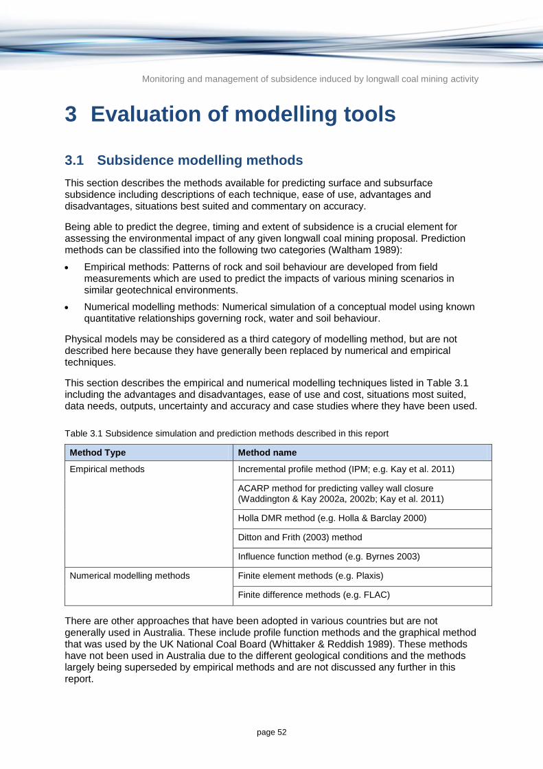
Monitoring and management of subsidence induced by longwall coal mining activity
page 52
3 Evaluation of modelling tools
3.1 Subsidence modelling methods
This section describes the methods available for predicting surface and subsurface subsidence including descriptions of each technique, ease of use, advantages and disadvantages, situations best suited and commentary on accuracy.
Being able to predict the degree, timing and extent of subsidence is a crucial element for assessing the environmental impact of any given longwall coal mining proposal. Prediction methods can be classified into the following two categories (Waltham 1989):
Empirical methods: Patterns of rock and soil behaviour are developed from field measurements which are used to predict the impacts of various mining scenarios in similar geotechnical environments.
Numerical modelling methods: Numerical simulation of a conceptual model using known quantitative relationships governing rock, water and soil behaviour.
Physical models may be considered as a third category of modelling method, but are not described here because they have generally been replaced by numerical and empirical techniques.
This section describes the empirical and numerical modelling techniques listed in Table 3.1 including the advantages and disadvantages, ease of use and cost, situations most suited, data needs, outputs, uncertainty and accuracy and case studies where they have been used.
Table 3.1 Subsidence simulation and prediction methods described in this report
Method Type Method name
Empirical methods Incremental profile method (IPM; e.g. Kay et al. 2011)
ACARP method for predicting valley wall closure (Waddington & Kay 2002a, 2002b; Kay et al. 2011)
Holla DMR method (e.g. Holla & Barclay 2000)
Ditton and Frith (2003) method
Influence function method (e.g. Byrnes 2003)
Numerical modelling methods Finite element methods (e.g. Plaxis)
Finite difference methods (e.g. FLAC)
There are other approaches that have been adopted in various countries but are not generally used in Australia. These include profile function methods and the graphical method that was used by the UK National Coal Board (Whittaker & Reddish 1989). These methods have not been used in Australia due to the different geological conditions and the methods largely being superseded by empirical methods and are not discussed any further in this report.

Monitoring and management of subsidence induced by longwall coal mining activity
page 53
All methods shown in Table 3.1 have been used in NSW coal mines over the last decade and the IPM, the Ditton and Frith (2003) method and the finite difference method (FLAC) have recently been used in Queensland.
3.1.1 Empirical methods
3.1.1.1 Holla Department of Mineral Resources (DMR) method (e.g. Holla 2000)
The maximum subsidence of the ground surface has generally been predicted using empirical methods in NSW. Before 1985, subsidence predictions were based on methods outlined in the Subsidence Engineers Handbook, first published by the UK National Coal Board in 1965 and revised in 1975 (NCB 1975). This involved the use of a series of graphs derived from numerous field observations in British mines, which allowed the amplitudes and shapes of the subsidence, tilt and strain profiles to be predicted (NCB 1975).
The method gave good results when applied to British mining situations, but when adopted in Australia it became clear that the field observations differed considerably from predicted values and were generally much less than predicted. This is because the strata that overlie the coal seams in British coalfields differ from those that occur in the coalfields of Australia and because the subsidence measurements in British coalfields were in some cases affected by multi-seam mining. An intensive research program was undertaken by the NSW Department of Mineral Resources (DMR) under the direction of Dr L Holla (DMR Principal Subsidence Engineer) to develop a predictive model that was more appropriate for Australian conditions.
Subsidence behaviour varied significantly between the Southern, Newcastle and Western Coalfields in NSW. Subsidence data from collieries in NSW were therefore studied separately for the three coalfields. Three handbooks were published from this work; the Southern Coalfield (Holla 1985), the Newcastle Coalfield (Holla 1987) and the Western Coalfield (Holla 1991).
The DMR handbooks were only applicable to single, isolated panels. However, additional research (Holla 1988) produced a graph that can be used to predict the maximum subsidence above a series of longwall panels for critical extraction conditions. The DMR handbooks and the graph published in 1988 were used to make subsidence predictions in NSW until more recent subsidence models were established, such as the IPM.
A revised handbook was published by the DMR (Holla & Barclay 2000) for the Southern Coalfield, which included graphs that can be used to predict the maximum subsidence over a series of longwall panels as a proportion of the extracted seam thickness, based on the width to depth ratio of the panels and pillars. The handbook can be used to establish an approximate transverse subsidence profile and to predict the maximum tilt, curvature and strain above a mined area, for a single panel.
When the width of an extracted panel, the average depth of cover, and the average extracted seam thickness are known, the following parameters can be predicted:
maximum subsidence value (Smax)
location of the inflection point (assumed to be at half Smax)
average goaf edge subsidence
limit of subsidence (defined by an AoD of 26.5 degrees).
Monitoring and management of subsidence induced by longwall coal mining activity
page 54
Once these parameters have been determined, an approximate subsidence profile can be produced as a line of best fit between the points of maximum subsidence, inflection, goaf edge subsidence and limit of subsidence, but this can only be done for a single, isolated panel. The predicted maximum tensile strain, compressive strain and tilt can be determined from the maximum subsidence and depth of cover, using factors obtained from graphs shown in the handbooks.
The Holla and Barclay (2000) handbook includes a series of graphs that can be used to predict the maximum subsidence parameters over a series of longwall panels in the Southern Coalfield. The predicted maximum tensile strain, compressive strain, tilt and maximum curvatures can be derived.
The limit of subsidence is determined from the depth of cover and the AoD, assumed to be 26.5 degrees for general use in the Southern Coalfield; hence, the limit of subsidence would generally be positioned at half the depth of cover from the perimeter of the extracted area.
Advantages and disadvantages
The advantages of the Holla DMR method are that it is simple to use and publicly available. The Holla and Barclay (2000) revisions are applicable to multiple panels.
Disadvantages are that when used for multiple panel situations, it provides only limited information regarding the potential subsidence movements. When used for single panels it can only approximately define the shape of the subsidence profile. The method provides point source information only and cannot provide appropriate predicted subsidence contours over a typical mining layout. The method also has limited applicability to areas outside the Southern, Western and Newcastle Coalfields in NSW.
Ease of use and cost
The Holla DMR method is relatively easy and inexpensive to use as a predictive tool, but can only be used to make approximate predictions of the maximum vertical subsidence, maximum strain, maximum tilt and maximum curvature.
Situations most suited
The method is often used by the NSW Mine Subsidence Board to determine the required design parameters for new structures being built in future mining areas, where the mine layouts are not yet known and can only be assumed. It is most suitable in these cases as it indicates a precautionary, worst case scenario.
Data needs (inputs)
The data inputs to the Holla DMR method are limited to the geometric features of mining, alone. Data inputs required are:
panel widths
chain pillar widths
average depth of cover
average seam thickness.

Monitoring and management of subsidence induced by longwall coal mining activity
page 55
Outputs
Outputs from the Holla DMR method are the maximum vertical subsidence, the maximum compressive strain, the maximum tensile strain, the maximum tilt, the maximum hogging curvature and the maximum sagging curvature over a single panel or longwall, or a series of longwall panels.
For single longwall panels, the approximate shape of the transverse subsidence profile can be determined by drawing a line through the point of maximum subsidence, the points of inflection, the subsidence at the goaf edges and the points of zero subsidence at the limit of subsidence defined by an AoD of 26.5 degrees. It should, however, be noted that the method does not take into account the variations in surface levels, seam levels and extracted seam thicknesses across a series of longwall panels, which generally occur in practice and affect the subsidence profile shapes and amplitudes (Holla 1985; Holla 1987; Holla & Barclay 2000).
Uncertainty and accuracy
The Holla DMR method has been compared with the IPM on many occasions (MSEC 2003) and has been found to give similar results for the maximum subsidence in cases where the panel widths and depths of cover are within the ranges that were used to develop the methods. It is less applicable in more recent mining projects where the widths of the longwall panels are significantly greater than they were when most of the data was collected for the development of the Holla DMR method. In contrast, the database on which the IPM is based has been continually updated.
In some cases the Holla DMR method has given predictions of the maximum subsidence values that are close to observed values and similar to IPM results. The Holla DMR method is based on a relatively small database that was available in the 1970s and 1980s which was generally obtained from narrower longwall panels than are currently mined and from mines with a relatively limited range of depth of cover. These limitations have affected the accuracy of the method when applied to situations outside those that have been used to develop the empirical database.
Case study applications
In recent years in Australia the IPM has generally been favoured over the Holla DMR method to make detailed predictions for new mining projects or for the assessment of impacts of subsidence on natural features and on items of surface infrastructure The IPM is favoured mainly since it reflects the results of more recent mining examples and therefore predicts with greater accuracy the subsidence over multiple panels. However, the Holla DMR method has been used in comparison with the IPM in support of longwall mining applications (e.g. MSEC 2003, unpublished). As discussed above, the maximum subsidence values obtained from the Holla DMR method compare closely with those from the IPM.
3.1.1.2 Ditton and Frith (2003) method for the Newcastle Coalfield
In 2003, a new empirical subsidence prediction model for the Newcastle Coalfield was developed by S Ditton and R Frith of Strata Engineering (Australia) Pty Ltd, under ACARP project C10023. The Ditton and Frith (2003) method enables the influence of massive strata units, such as conglomerate and sandstone channels, chain pillar compression and regional structure to be included in the prediction of subsidence over single and multiple longwall and miniwall panels. The research included the collation of previously published data by mining

Monitoring and management of subsidence induced by longwall coal mining activity
page 56
company personnel (primarily from Creech 1995) and data obtained directly from mines. Subsidence data for more than 50 longwall panel centre lines and cross lines and geological data from more than 200 boreholes is included in the model to represent the full range of overburden conditions likely to occur in the Newcastle Coalfield.
The method is based on conceptual models of overburden behaviour that link the physical relationship between geometrical parameters and the resulting subsidence. The database contains single and multiple longwall panel data only (i.e. there are no pillar extraction or multi-seam data included in the model). Statistical methods have been used to assess the standard error of the equations developed and to allow subsidence parameter predictions to be made within known levels of confidence.
The model predicts maximum subsidence, panel goaf edge subsidence, angle of draw, maximum transverse and longitudinal tilt, curvature, horizontal displacement and strain; and the locations of the above parameters over the longwall panel to allow reconstruction of the subsidence profile.
The first stage of the method predicts the maximum subsidence above a single, isolated longwall panel. The influence of geology is then assessed before subsequent predictions of chain pillar subsidence or multiple panel effects are added to the single panel prediction. Multi-panel effects are included by adding empirical estimates of surface subsidence over chain pillars (due to compression) to the maximum subsidence predictions for single panels.
When the location of the maximum subsidence, panel goaf edge subsidence and limit of subsidence, defined by the AoD, have been obtained, the shape of the subsidence profile is defined by interpolating between the points at which the subsidence has been predicted. The profiles can be defined in both the transverse and longitudinal directions.
Ditton Geotechnical Services Pty Ltd modified the original Ditton and Frith (2003) method in 2009 to allow calibration against an influence function model called Surface Deformation Prediction System (SDPS) developed by the Polytechnic Institute for the US coalfields (Ditton Geotechnical Services 2009). The SDPS program allows a wider range of topographic and complex mining layouts (including longwall and pillar extraction panels) to be assessed (Ditton Geotechnical Services 2009).
Advantages and disadvantages
The advantage of the Ditton and Frith (2003) method is that it takes into account the presence and thickness of the conglomerate and sandstone channels, which often overlie the coal seams of the Newcastle Coalfield and are known to significantly reduce subsidence related movements by spanning across the goaf. It is also a publicly available method and not proprietary.
The method can predict the maximum incremental subsidence value that can be used in conjunction with the ACARP method for predicting valley related movements that are used to assess impacts on aquatic ecosystems (Section 3.1.1.5 describes the ACARP method).
Disadvantages of the method are that it is based on empirical data collected from the Newcastle Coalfield only so has limited application in areas which differ substantially from the Newcastle Coalfield. Using a cubic spline curve to define the shapes of subsidence profiles by interpolation between a limited number of points can only provide approximate shapes, which may differ significantly from the shapes of the profiles that are observed in practice. However, the predicted shapes of the subsidence profiles and subsidence troughs may be adequate for most practical purposes.
Monitoring and management of subsidence induced by longwall coal mining activity
page 57
Ease of use and cost
The method is relatively easy and inexpensive to use compared to more complex methods such as the IPM.
Situations most suited
The method is particularly suitable for use in the Newcastle Coalfield, because it is based on data collected in that coalfield.
The model is suitable for use in other coalfields that have similar geometry, geology and cover depths between 70 and 350 m, with appropriate calibration to local data.
Data needs (inputs)
The required data inputs to the Ditton and Frith (2003) method are:
mine layout
panel widths
cover depths
seam working heights
rock mass density
rock mass strength (unconfined compressive strength)
rock mass stiffness (Young’s Modulus)
Poisson’s ratio
strata unit thickness, in particular singular thick massive strata units that make up a significant proportion of the overburden (greater than 10 per cent)
location of the strata units above the workings.
Outputs
Outputs from the Ditton and Frith (2003) method are the maximum subsidence, panel goaf edge subsidence; AoD; maximum transverse and longitudinal tilt, curvature, horizontal displacement and strain; and the locations of the above parameters over the longwall panel.
Uncertainty and accuracy
The Ditton and Frith (2003) method has been found to give reasonable results in most cases where reviews have been undertaken by MSEC of unpublished reports in the Newcastle Coalfield (A Waddington 2013, pers. comm.)4.
4 Waddington, AA, Director, Mine Subsidence Engineering Consultants. Level 1, 228 Victoria Avenue, Chatswood,
NSW, 2067.

Monitoring and management of subsidence induced by longwall coal mining activity
page 58
Ditton Geotechnical Services (2009) presented data to support that:
predictions of maximum single panel subsidence, chain pillar subsidence, tilt, curvature, strain and the AoD can be made within a 90 per cent confidence interval
maximum subsidence predictions are based on 95 per cent confidence limits (or 5 per cent probability of exceedance), which in practice have rarely been exceeded.
Case study applications
The method has been used to prepare subsidence predictions and impact assessments to support development applications and longwall mining applications at a number of collieries in NSW and Queensland. For example, it was used in 2009 to predict subsidence over longwall panels at the Narrabri Coal Mine in NSW for Whitehaven Coal (Ditton Geotechnical Services 2009).
3.1.1.3 Influence function methods
Influence function methods are empirical methods used to predict the influence exerted at the surface by substrata excavations such as those related to mining or civil works. The method is especially useful in longwall subsidence prediction due to its ease of use and simplistic outputs. The methods predict deformations using mathematical functions of site specific calibrated data (Seedsman & Dawkins 2006). In the case of greenfield sites where no measured data are available, performance data of pillars, roof and floor can be estimated from past experience in similar conditions at other sites.
The shape of the subsidence profile across a longwall panel or group of panels is approximated using Gaussian functions. The profile is then represented over a grid of points enabling contouring of surface depressions. The visualisation of the surface subsidence can be presented as high density grids for a range of subsidence parameters and can provide high resolution graphics (Byrnes 2003).
One influence function method, the Surface Deformation Prediction System (SDPS) has been used successfully in Australia to visualise surface subsidence over various mine layouts by Seedsman Geotechnics Pty Ltd. The SDPS software was developed for the Office of Surface Mining, Reclamation and Enforcement (OSMRE) in the US (Byrnes 2003). The SDPS method uses a bell shaped Gaussian curve as the influence function. However, prediction methods using numerous other mathematical functions have been used (Byrnes 2003).
The output grid representing the subsidence parameter of interest can be represented in several formats including lined contour plans, coloured solid contour plans or shaded relief plans. The parameters that can be represented include vertical subsidence, tilt, curvatures, strains and horizontal movements (Byrnes 2003). An example of a shaded solid contour for vertical subsidence is provided in Figure 3.1.
Advantages and disadvantages
An advantage of the influence function method is the ability to visualise subsidence. The ability to present data outputs as contour or topographic plans is an effective way to communicate the prediction to both technical and non-technical audiences. As the method predicts subsidence across the surface rather than in profile, it also has the ability to generate lines across the surface to illustrate subsidence across points of interest, such as rivers or infrastructure. This is particularly useful when considering critical structures such as electrical towers or large buildings.

Monitoring and management of subsidence induced by longwall coal mining activity
page 59
Model run times are very short, large models with closely spaced prediction points can be run in approximately 15 minutes on a computer of average processing speed (Byrnes 2003). Due to the short run time, fine tuning of calibrations can be undertaken by adjusting input parameters repeatedly until the required calibration has been achieved (Byrnes 2003). The programs are readily available and can be run on Windows based operating systems.
One disadvantage is that the program relies on project data to calibrate the function. If data is not available at or near the mine of interest, then the accuracy of the outputs will be reduced (Byrnes 2003). Finally, it is important to remember that this is still only an empirically-based influence function method albeit arranged to superpose subsidence profiles on existing topography (Figure 3.1). The convincing realism of such profiles is only as accurate as other empirically-based methods.
© Copyright, Byrnes (2003)
Figure 3.1 An output of the surface deformation prediction system (SDPS) showing a shaded relief surface of subsided topography
Ease of use and cost
The equations for the influence function method are freely available and in the public domain. The SDPS software is available from the Office of Surface Mining, Reclamation and Enforcement (OSMRE) in the US (Byrnes 2003).
Situations most suited
The method is most suited to predicting subsidence in landscapes with existing survey data, characterised with flat or gently sloping topography rather than areas of large topographic relief such as valleys (Seedsman & Dawkins 2006).
Monitoring and management of subsidence induced by longwall coal mining activity
page 60
Data needs (inputs)
The SDPS uses five input variables:
angle of influence (angle to zero subsidence)
maximum vertical subsidence (Smax)
edge effect
location of inflection point (compensation width)
depth of cover.
Calibrating the function to a specific site requires:
subsidence factor ((Smax/T ratio) as a percentage, where T is extraction thickness)
location of inflection point (compensation width)
ratio of strain to curvature
angle of influence
panel layouts
seam thickness
depth of cover.
Outputs
Outputs of the influence function method are maximum values for vertical subsidence, tilts, curvatures, strains and horizontal movements. These outputs can be presented in any arbitrary direction. All possible outputs can be represented as gridded surfaces enabling visualisation of the data (Byrnes 2003).
Uncertainty and accuracy
Influence functions have not been extensively used so validation of accuracy has not been well studied. The influence function method uses the same method of calibration as point and profile methods, which have been suggested to be accurate to within 10 per cent for vertical subsidence (Byrnes 2003). Accuracy of tilt and strain predictions have yet to be assessed (Byrnes 2003). The method is based on curve fitting routines that do not account for the mechanisms of deformation (Seedsman & Dawkins 2006).
Case study applications
The influence function method has been used successfully in Australia to predict longwall subsidence in both Queensland and NSW. The SDPS method was used to predict subsidence in shallow longwall panels with non-yielding chain pillars and deep longwall panels with yielding chain pillars in coal mines located in the Newcastle Coalfield (Waddington & Kay 1998a) and the Southern Coalfields (Holla 1985), respectively.
SDPS modelling in the Newcastle Coalfield gave favourable results when comparing predicted against measured vertical subsidence (Byrnes 2003). However, predicted strains differed substantially from the measured strains (up to 700 per cent). Byrnes (2003) suggested that the differences between the predicted and measured strains could be the result of thin soil cover and widely spaced joints in the near surface bedrock.
Monitoring and management of subsidence induced by longwall coal mining activity
page 61
SDPS modelling of deep longwall panels with yielding chain pillars was used to predict subsidence of a super-panel (combination of panels). The results found that both the subsidence and strain predictions were close to measured data (Byrnes 2003). The mine is characterised by a thick zone of weathered and highly fractured rock. Byrnes (2003) suggested that these geotechnical conditions may be responsible for reducing the likelihood of localised fracturing leading to strain peaks as found in the shallow panel results.
3.1.1.4 The incremental profile method (IPM)
The NSW Department of Planning wrote that:
‘…in theory, the surface displacement profile over mine workings at any point in time can be constructed by summing the increments of vertical displacement arising from the mining of each panel in these workings’.
© Copyright, NSW DoP (2008)
This was shown to be the case by Waddington and Kay (1995). The Australian coal mining industry has funded research to effectively ‘reverse engineer’ the subsidence prediction process, using large databases of subsidence information relating to the NSW Southern and Newcastle Coalfields to define the characteristic shape for each increment of vertical displacement resulting from a mining operation. Once the vertical displacement profile has been created, it can be used to calculate tilt, curvature and strain in the same manner as that described for the profile function method. This prediction technique offers a number of benefits over other empirical techniques because variations in depth, seam thickness and seam dip can be taken into account, as well as the influence of multiple mining panels. Subsidence predictions can also be produced at any nominated point on the ground surface.
Observed incremental subsidence profiles are derived by subtracting the observed subsidence profile before mining from the observed subsidence profile after mining and these observed incremental profiles show the settlement resulting from the extraction of an individual panel. Incremental subsidence profiles are estimated for individual longwall panels. The estimates of subsidence for all panels are then combined to produce the total subsidence profile at the end of mining any one panel and the total subsidence at the end of mining a series of panels (e.g. Figure 3.2). Whilst the final subsidence profiles over a series of longwall panels are usually irregular, incremental subsidence profiles have been found to be consistent in shape throughout the NSW Southern, Western and Newcastle Coalfields.
The regularity and consistency of the shapes of the incremental subsidence profiles over the solid coal side of the longwall panels led to the development of the IPM (Waddington & Kay 1995). The solid coal side of the panel is the intact side of the coal face. Prediction of the amplitude and shape of the subsidence profile allows the tilt and curvature to be determined as the first and second derivative of the profile. That is, the tilt profile is obtained by plotting the slope of the subsidence profile and the curvature profile is obtained by plotting the slope of the tilt profile.
The final subsidence at any point on the ground surface can be predicted using the IPM by adding the appropriate increments of subsidence from each longwall panel at that point. The predicted subsidence profiles obtained using the IPM reflect the way in which each parameter varies over the mined area and indicate the movements that are likely to occur at any point on the surface.
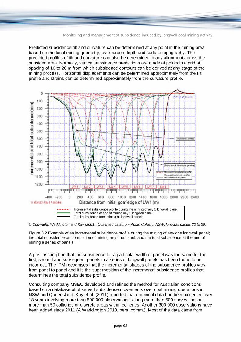
Monitoring and management of subsidence induced by longwall coal mining activity
page 62
Predicted subsidence tilt and curvature can be determined at any point in the mining area based on the local mining geometry, overburden depth and surface topography. The predicted profiles of tilt and curvature can also be determined in any alignment across the subsided area. Normally, vertical subsidence predictions are made at points in a grid at spacing of 10 to 20 m from which subsidence contours can be derived at any stage of the mining process. Horizontal displacements can be determined approximately from the tilt profile and strains can be determined approximately from the curvature profile.
© Copyright, Waddington and Kay (2001). Observed data from Appin Colliery, NSW, longwall panels 22 to 29.
Figure 3.2 Example of an incremental subsidence profile during the mining of any one longwall panel; the total subsidence on completion of mining any one panel; and the total subsidence at the end of mining a series of panels
A past assumption that the subsidence for a particular width of panel was the same for the first, second and subsequent panels in a series of longwall panels has been found to be incorrect. The IPM recognises that the incremental shapes of the subsidence profiles vary from panel to panel and it is the superposition of the incremental subsidence profiles that determines the total subsidence profile.
Consulting company MSEC developed and refined the method for Australian conditions based on a database of observed subsidence movements over coal mining operations in NSW and Queensland. Kay et al. (2011) reported that empirical data had been collected over 18 years involving more than 500 000 observations, along more than 500 survey lines at more than 50 collieries or discrete areas within collieries. Another 300 000 observations have been added since 2011 (A Waddington 2013, pers. comm.). Most of the data came from
Incremental subsidence profile during the mining of any 1 longwall panel Total subsidence at end of mining any 1 longwall panel Total subsidence from mining all longwall panels

Monitoring and management of subsidence induced by longwall coal mining activity
page 63
NSW collieries, with the exception of 25 000 observations from 50 survey lines over 72 longwall panels from four collieries in the Bowen Basin in Queensland (Cook Colliery, Kenmare Colliery, Grasstree Mine and Moranbah North Mine). Data have also been collected from the Kestrel Mine in the Bowen Basin, but these have not yet been entered into the database (A Waddington 2013, pers. comm.).
Advantages and disadvantages
Advantages of the IPM (A Waddington 2013, pers. comm.) are listed below.
It can be implemented quickly and cheaply relative to numerical modelling methods.
It is based on standard profile shapes for each mining area and can be further refined by calibrating to locally observed data if available. The method can also be calibrated to model the reduced levels of subsidence that are known to occur where thicker and more competent strata are present in the overburden. It can also be calibrated to model the increased subsidence that is likely to occur in multi-seam mining situations.
The method can be used to model the effects of alternative mine layouts with different pillar and panel configurations and to compare the potential impacts of tilts and curvatures for different mine layouts as an aid to mine planning.
Approximate predictions of ground strains and horizontal displacements can be obtained from the predicted tilts and curvatures, though such predictions have a lower level of confidence. Statistical analysis of observed strains from the empirical database can be used to provide confidence intervals for strain resulting from both conventional and anomalous ground movements.
The IPM can be used to predict subsurface subsidence above the fracturing and caving zone when local data are available to calibrate against (e.g. extensometer data). In these situations, the IPM can provide valuable guidance on the vertical dilation and vertical shear stress at various horizons above the coal seam.
Disadvantages of the IPM are listed below.
The method does not directly take into account the influence of weak roof or floor conditions that can lead to increased ground movements in some situations. In these cases the technique can be calibrated against results obtained by numerical modelling (A Waddington 2013, pers. comm.).
The method does not estimate the distributions of deformations below the surface nor the related and dependent changes in permeability resulting from caving, fracturing or subsurface subsidence. Numerical modelling methods are best suited for situations where changes in aquifer behaviour are required.
Ease of use and cost
The IPM has been developed by MSEC into proprietary software by MSEC and is available at a cost. However, the basis of the method has been explained in a number of published papers and numerous reports (e.g. Waddington & Kay 1995, 1998a, 1998b). At present, MSEC is the sole user of the method. It could be adopted by others based on the published methodology but would require a significant database of observed subsidence data and a considerable amount of analysis to develop the method to the level that has been achieved by MSEC since 1996.
Monitoring and management of subsidence induced by longwall coal mining activity
page 64
The method is easy to use and facilitates interpretation of results and modification of inputs for alternative mine layouts. Computing time required for the preparation of subsidence predictions is now a few days, which has reduced the costs of modelling.
Situations most suited
The IPM is based on empirical data, most of which were observed over longwall operations in NSW and Queensland. It is therefore most suited to the prediction of ground movements over proposed longwall mining areas as opposed to movement over irregular pillar extraction areas in bord and pillar mining operations. The method has been successfully used over rectangular areas of pillar extraction, and is less applicable in situations where the geotechnical conditions are substantially different from those used to develop the empirical techniques. In these situations, the IPM can still be used but the results need to be calibrated against local conditions or adjusted using published relationships between maximum surface subsidence and width-to-depth ratios (A Waddington 2014, pers. comm.). More information on this issue is provided below in the discussion on method accuracy.
The IPM is best suited to predicting surface subsidence and is less suited to situations where subsurface subsidence predictions are required. However, where subsurface subsidence predictions are required, it can be calibrated against local data (e.g. extensometer data), which provides valuable guidance on the vertical dilation or vertical shear stress at various horizons above the extracted seam (A Waddington 2014, pers. comm.).
The method has been used in a wide variety of geological settings throughout the coalfields in NSW and Queensland and has also been used in Pennsylvania, USA, in connection with damage to the Ryerson Station Dam (Pennsylvania DEP 2010).
Most of the data in the database were collected in single seam mining situations, though more multi-seam data have become available in recent years. Whilst there is less data available to model multi-seam situations and the results are therefore less certain, there is sufficient data to prepare conservative models (A Waddington 2014, pers. comm.). The IPM is constantly being refined as new subsidence observations are collected and analysed. Multi-seam subsidence prediction models have been developed based on the currently available data and will be further refined as more data becomes available from multi-seam operations.
Data needs (inputs)
Data inputs to the IPM are usually the mine layout plans, the seam level contours, the surface level contours, the proposed mining heights, the proposed mining sequence, the speed of mining, the lithology of the overburden, and local subsidence survey data from previously mined areas. These inputs are generally sufficient to predict the likely ground movements and subsidence effects (A Waddington 2013, pers. comm.).
Outputs
The IPM can independently predict the subsidence, tilts and curvatures at any point across the mining area. The output can be a prediction of the subsidence parameters at a specific location or along a linear series of points to generate a cross-section in any direction and along any alignment. The output can also be a series of predictions of subsidence, tilts and curvatures in a regular grid of points over the whole of the mining area, from which the shape of the subsidence trough can be visualised and from which subsidence contours can be generated. Sections can be taken through the subsidence troughs along linear structures or

Monitoring and management of subsidence induced by longwall coal mining activity
page 65
features such as drainage lines, roads, railways, canals and pipelines to determine the specific subsidence effects likely to affect those structures.
Uncertainty and accuracy
Historical analysis
Most of the information on observed versus predicted subsidence using the IPM resides in unpublished mining reports or government responses to impact assessments. However, the IPM has been used in more than 600 studies and reports since 1996 and has gained acceptance by mining companies and government regulators in NSW and Queensland. It has also been accepted by Commissions of Inquiry, Planning Assessment Commissions and the Land and Resources Tribunal in Queensland (A Waddington 2013, pers. comm.).
Even though empirical techniques such as the IPM can be applied with limited local data, the accuracy of the method is greatly improved if local subsidence data can be used to calibrate against. Calibration data can include subsidence data from nearby mines of similar geological and geotechnical characteristics. As longwall coal mining progresses, it is a common practice for empirical modelling predictions of subsidence from unmined longwall panels to be calibrated against the subsidence monitoring results collected from mined panels. In this way, the modelling predictions are being continually improved.
There are a small number of cases in which observed movements have exceeded predicted movements and in those cases it has been inferred by MSEC that the localised aberrations were due to variations in the local geology that were not apparent from the exploration boreholes (MSEC 2010). In some cases, the ground surface behaves in a way which is unpredictable and these are referred to as anomalous ground movements (Section 2.2.1.3). In the Southern Coalfield, such anomalous movements have been found to occur in approximately one per cent of the observed subsidence movements (MSEC 2004).
Anomalous ground movements and movements in valleys are gradual. These ground movements are likely to result in higher than normal levels of strain and hence greater impacts (Waddington & Kay 2002b). They can be detected at an early stage from regular monitoring results, and mine plans and mining methods can then be refined so that the impacts remain within acceptable limits. Surface water resources have been successfully protected from potential subsidence related impacts by adjustments to mining plans in a number of cases (MSEC 2010).
Predicted subsidence using the IPM has been exceeded by a statistically significant amount on only one occasion; over the commencing ends of Longwall panels 24A and 25 at Tahmoor Colliery, adjacent to the Bargo River Gorge, and earlier bord and pillar workings. MSEC (2003) suggests that the proximity of the site to the Nepean Fault and a bend in the Bargo River provided unusual geotechnical conditions at the site. Further study of this unusual phenomenon by Gale and Sheppard (2011) indicated that the site characteristics were outside of the database typically used for prediction. Gale and Sheppard (2011) also postulated that the locally depressed watertable may have altered the geomechanical properties of the strata below the base of the Bargo River. The additional vertical subsidence in this case was not accompanied by increased tilts, curvatures or strains.
Further information on the reliability of predictive methods is provided in Chapter 4 of MSEC (2010), which includes a number of graphs showing comparisons of predicted and observed movements. This report was prepared in October 2010 to support the EIS for the BHP Billiton Illawarra Coal Bulli Seam Operations, which was submitted to the

Monitoring and management of subsidence induced by longwall coal mining activity
page 66
Commonwealth Department of Sustainability, Environment, Water, Population and Communities (now the Department of the Environment). Comparison of predicted versus observed surface subsidence levels presented in MSEC (2010) show that the version of IPM applied by MSEC is conservative in that there is a low probability that predicted levels of subsidence will be exceeded.
New analysis
This section summarises an assessment of the IPM for surface subsidence prediction as applied by MSEC (MSEC 2014; provided at Appendix A). Given the widespread use of the IPM in NSW and Queensland, and the lack of published comparison of observed and modelled data, there is a need to further investigate the accuracy of the method.
MSEC has accumulated a significant database to allow comparison between predicted subsidence using the IPM and observed subsidence. For this report, MSEC consolidated and presented data from a collection of collieries without linking a particular mine to individual subsidence estimates or measurements. Of particular interest for this report is the comparison of IPM accuracy between the Sydney Basin (where most of the empirical data for the IPM has been collected) and the Queensland coal basins, where there have been relatively few applications of the IPM.
Data analysed in MSEC (2014) is not a comprehensive dataset of all predicted and observed data available but rather an analysis of the readily available digital data on maximum subsidence. The analysis only considers the accuracy of prediction of maximum subsidence and makes no assessment of the accuracy of other subsidence related parameters predicted by the IPM, including incremental subsidence, tilts and curvatures.
Observed and predicted results were analysed using two statistical methods:
probability of exceedance, which is particularly useful in assessing the likelihood of an unwanted event occurring. It also indicates the level of conservatism included in predictions, in that a low probability of exceedance indicates a conservative prediction
root mean square (RMS) error, which is used to assess the goodness of fit of a modelled dataset to an observed or measured dataset. It is commonly used in groundwater modelling to help illustrate the accuracy of model calibration (modelled data are compared to measured groundwater heads). The RMS error helps quantify the level of scatter in a plot of measured data versus predicted data. Squaring the deviation from the mean results in all deviations from the mean, whether higher or lower, being incorporated.
In addition, accuracy of the results was analysed by calculating the scaled RMS (SRMS) error, which is the RMS error divided by the range in observed or measured values:
The SRMS error has the same advantages as the RMS error described above and also provides a normalised statistic that is useful for comparison between models at different locations. The SRMS value is often used in groundwater modelling to provide an estimate of goodness of fit that is comparable between different models, as it accounts for the greater difficulty to develop a model to match a wide range of heads compared to those required to model a narrow range of heads.
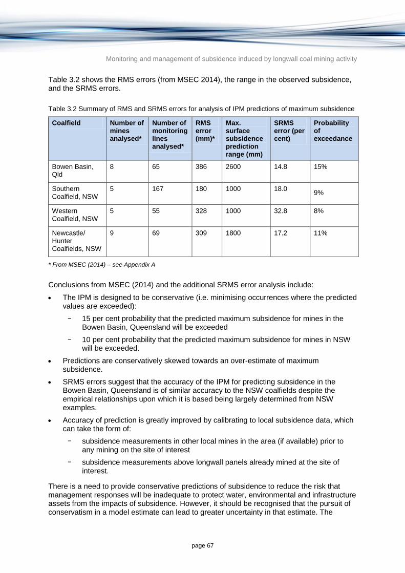
Monitoring and management of subsidence induced by longwall coal mining activity
page 67
Table 3.2 shows the RMS errors (from MSEC 2014), the range in the observed subsidence, and the SRMS errors.
Table 3.2 Summary of RMS and SRMS errors for analysis of IPM predictions of maximum subsidence
Coalfield Number of mines analysed*
Number of monitoring lines analysed*
RMS error (mm)*
Max. surface subsidence prediction range (mm)
SRMS error (per cent)
Probability of exceedance
Bowen Basin, Qld
8 65 386 2600 14.8 15%
Southern Coalfield, NSW
5 167 180 1000 18.0 9%
Western Coalfield, NSW
5 55 328 1000 32.8 8%
Newcastle/ Hunter Coalfields, NSW
9 69 309 1800 17.2 11%
* From MSEC (2014) – see Appendix A
Conclusions from MSEC (2014) and the additional SRMS error analysis include:
The IPM is designed to be conservative (i.e. minimising occurrences where the predicted values are exceeded):
− 15 per cent probability that the predicted maximum subsidence for mines in the Bowen Basin, Queensland will be exceeded
− 10 per cent probability that the predicted maximum subsidence for mines in NSW will be exceeded.
Predictions are conservatively skewed towards an over-estimate of maximum subsidence.
SRMS errors suggest that the accuracy of the IPM for predicting subsidence in the Bowen Basin, Queensland is of similar accuracy to the NSW coalfields despite the empirical relationships upon which it is based being largely determined from NSW examples.
Accuracy of prediction is greatly improved by calibrating to local subsidence data, which can take the form of:
− subsidence measurements in other local mines in the area (if available) prior to any mining on the site of interest
− subsidence measurements above longwall panels already mined at the site of interest.
There is a need to provide conservative predictions of subsidence to reduce the risk that management responses will be inadequate to protect water, environmental and infrastructure assets from the impacts of subsidence. However, it should be recognised that the pursuit of conservatism in a model estimate can lead to greater uncertainty in that estimate. The

Monitoring and management of subsidence induced by longwall coal mining activity
page 68
trade-off between the degree of conservatism and accuracy is a decision for industry and government alike and there is no suggestion that this trade-off needs to be adjusted from the current norm in Australia. However, it is important for the results of the IPM to be viewed in this context.
An objective assessment of any prediction is only achieved by reviewing both the deviation from observed results (a measure of accuracy) and the probability of exceedance (a measure of conservatism). Probability of exceedance alone cannot give a true indication of the accuracy of the method.
There is general acceptance that all models of underground caving processes will include errors and inaccuracies. The process of subsidence above a mined longwall panel involves a wide range of interacting and complex processes, all of which have varying degrees of predictability. Some processes are entirely unpredictable (e.g. anomalous movements; Section 2.2.1.3). There is a widely held understanding in the field of groundwater modelling that predictive uncertainty should be acknowledged and quantified (Barnett et al. 2012), which is also the case for subsidence prediction. It would be beneficial for results of the IPM (and any other subsidence prediction method) to be accompanied by a quantification of uncertainty. Where the uncertainty is difficult to calculate for a site of interest, such quantification could default to more generalised assessments of uncertainty such as those presented in this study.
As the empirical database of subsidence measurements upon which the IPM is based increases, so will the accuracy of prediction. This is particularly the case for Queensland coal basins where there are currently relatively few case studies. The higher probability of exceedance in the Bowen Basin relative to NSW coalfields suggests that a degree of caution is required when applying the IPM in the Bowen Basin, although SRMS errors suggest the accuracy of Bowen Basin predictions are no worse than NSW coalfield predictions. Similarly, a great degree of caution will be required when applying the IPM in the Galilee Basin where there are no measured subsidence data.
Finally, formalising an acceptable level of accuracy in Australia may warrant further work, along with guidance on methods to report predictive accuracy and uncertainty.
Case study applications
The IPM has been used as the basis for management plans to protect major surface infrastructure, including the Hume Highway, (Kay et al. 2007, 2011; Kay 2012), the Main Southern Railway, (Ho et al. 2011; Pidgeon et al. 2011; Kay 2012), the Cataract Tunnel and Upper Canal (Swarbrick & Pinkster 2011; Vergara et al. 2011), a major gas pipeline easement (Cheng & Colvin 2004) and the township of Tahmoor (Waddington et al. 2011). It has also been used as a tool to prepare management plans to protect natural features and to establish desirable set-back distances to more sensitive features.
An example of the IPM application is the Environmental Impact Assessment of the Wallarah 2 Coal Project (NSW PAC 2010). The NSW Government report on the Wallarah 2 Coal Project noted that:
‘Differences in depth, mining height and geology distinguish the Wallarah 2 Study Area from other NSW mining districts, so the proponent has adopted a hybrid approach to subsidence prediction. A mathematical model was developed by Strata Control Technologies based on numerical techniques, validated against known geological conditions and subsidence outcomes at other mining sites, and applied to a number of cross-sections through the Study Area. The outcomes were then utilised to calibrate
Monitoring and management of subsidence induced by longwall coal mining activity
page 69
the Incremental Profile Method to Wallarah 2 conditions so that it could be utilised across the whole site…’
© Copyright, NSW PAC (2010)
The Commission concluded that:
‘…the subsidence prediction methodology and outcomes are reasonable and adequate for the purposes of its assessment.’
© Copyright, NSW PAC (2010)
3.1.1.5 ACARP method for predicting valley related movements
The ACARP method is an empirical method for predicting valley related mining induced movements, based on an extensive database of observations in NSW. The method was developed by MSEC, CSIRO, and the University of NSW (ACARP 2002). The method has been further refined since 2002 using additional data collected by collieries in NSW (Kay et al. 2011).
ACARP (2002) discussed valley closure and upsidence mechanisms based on horizontal stress redistribution as a precursor to a discussion of the empirical method. Seedsman and Dawkins (2006) presented a complementary model for valley closure and upsidence based on the displacement of joint-bounded rock blocks. The model suggests sagging/hogging induced lateral translation of joint-bounded blocks into valley free faces results in valley closure or upsidence due to lack of lateral restraint.
In a sagging environment, blocks translate sideways down sag towards the valley free face. As there are no blocks in the valley to resist lateral translation, the end block will translate into the valley resulting in unrecoverable closure. In the case of a hogging environment, the unrestrained end block adjacent to the valley free face will tilt at the hog, resulting in upsidence (Seedsman & Dawkins 2006).
The ACARP method enables the prediction of closure and upsidence in gorges, river valleys, creek alignments and other watercourses. Predictions at any point in the valley usually include closure of the valley sides, uplift due to bulging and buckling of the strata in the base of the valley, and the potential compressive strain across the valley. Predicted effects are used to assess the likely levels of impact to the watercourses and the potential for the diversion of surface water into the dilated strata caused by upsidence in the base of the valley. These voids can extend to a depth of 10 to 15 m or more, depending on the scale of the valley, but are generally limited to the near-surface strata, where vertical confinement by overlying strata is the least (Waddington 2006).
The ACARP method uses four parameters to make the predictions using four graphs for closure and four graphs for upsidence:
maximum incremental subsidence of the longwall being mined
depth of the valley at the point under consideration
transverse distance from the side of the longwall
longitudinal distance from the end of the longwall.
The transverse distance is used to obtain an initial closure or upsidence value from the first of the graphs and the other three graphs are used to obtain adjustment factors based on the

Monitoring and management of subsidence induced by longwall coal mining activity
page 70
other three parameters. The final value of closure or upsidence is obtained by multiplying the initial value by the three adjustment factors. The compressive strain is obtained from the closure value using a graph that plots the relationship between maximum compressive strain and closure.
A recent ACARP research project investigated the effects of local geology on the upsidence and closure movements in valleys (Kay 2014). The report provides a review and analysis of this data to assess the influence of 30 potential geological and topographical factors on the observed valley closure movements. Although the report discusses the various mechanisms that are believed to cause these observed closure movements, full or complete data sets could not be gathered on all the complex and interrelated factors that influence observed valley closure. The project was not expected to provide a complete understanding of why valley closure movements happen (Kay 2014). However, the analysis has progressed the understanding on the important factors in valley wall closure.
Comparison of actual and predicted data by Kay et al. (2011) shows that the method produces conservative results (i.e. tendency to over-predict in most cases) as shown in Figure 3.3. This is not surprising because the method was based on a series of upper-bound curves over the available data in graphs that were published in the ACARP management information handbook on the undermining of cliffs, gorges and river systems (Waddington & Kay 2002b). Subsets of the empirical data relevant to specific cases can be used to refine the upsidence and closure predictions, if more realistic rather than conservative predictions are required. The method over-predicts upsidence and closure movements in more than 95 per cent of cases (Kay et al. 2011).
© Copyright, Kay et al. (2011)
Figure 3.3 Comparison of predicted versus observed valley closures using the ACARP method

Monitoring and management of subsidence induced by longwall coal mining activity
page 71
Advantages and disadvantages
The main advantage of the ACARP method is that it is the only method published for the prediction of closure and upsidence in gorges, river valleys, creek alignments and other watercourses.
One of the disadvantages is that the original method ignored local geology, because the geological data were not available when the research project was carried out. It is hoped that current research will satisfactorily address this issue and provide more site-specific predictions based on the local geological setting. The method is based on observed data that were collected predominantly from the NSW Southern Coalfield and could be extended for use in other coalfields. At this stage there are only limited data available from other coalfields. In the absence of a better method, it has been used in other coalfields and is thought to provide conservative results. The method has been used at a coal mine in Pennsylvania and the predicted movements compared well with the observed movements (Pennsylvania DEP 2010).
Another potential disadvantage is that the mechanism of failure of the strata in the base of a valley during subsidence is not fully understood. It is believed to be driven by changes in the horizontal stress field as mining occurs. Stresses in the strata at the surface are measured and changes in stress as mining occurs are not normally recorded. It is therefore impossible to model the relationship between the horizontal ground stress and the valley related impacts with certainty (Waddington & Kay 2002b; Kay et al. 2007). This lack of linkage between observed impacts and causal mechanisms is a universal shortcoming of all empirical methods, not just this method.
Another problem arises when predicting upsidence using the ACARP method, since it is a localised effect that depends on the nature of the strata in the base of the valley and the mode of failure, which can include sliding, shearing, crushing and buckling. The model therefore includes cases in which buckling occurs and in which the observed upsidence is increased by the buckling. The method uses an upper-bound curve to make predictions so the upsidence tends to be over-predicted. It should be noted that the majority of subsidence surveys measure the subsidence movements at survey marks that are 20 mm apart along an individual survey line so it is possible that any local buckling of the strata that occurs between survey pegs will not be apparent from the survey data. The method can be used to predict upsidence along a river or creek alignment to indicate the likely changes in gradient and the potential for ponding or scouring to occur, but the upsidence value does not readily lend itself to the assessment of physical impacts (MSEC 2010).
Valley closure is an en masse movement of the valley sides towards each other in a down slope direction and is less affected by the mode of failure of the strata in the base of the valley (Waddington & Kay 2002b). Valley closure has therefore been chosen as the primary parameter that should be used to assess the potential physical impacts caused by the closure of the valley sides and the failure of the base of the valley resulting from a concentration of compressive stress. Failure of the base of the valley can occur in a number of ways and the resulting upsidence can vary considerably from place to place along the valley. Closure is a much less variable parameter and is a more useful measure of the likely extent of the physical impact, which is seen to increase as the closure increases (Waddington & Kay 2002b).

Monitoring and management of subsidence induced by longwall coal mining activity
page 72
Ease of use and cost
The method only requires four parameters to determine the upsidence, closure and compressive strain values, so is relatively easy and inexpensive to use as a predictive tool. It does require the user to predict the incremental subsidence as one of the input parameters, which can readily be achieved using the IPM but can also be achieved using other methods such as the Ditton and Frith (2003) method.
The basis for the method has been described in reports by MSEC in support of development and mining applications, some of which are in the public domain (e.g. MSEC 2009). More information about the method can be found in MSEC (2010), Waddington and Kay (2003), Kay et al. (2007), and Kay et al. (2011). However, details of the method remain commercial in confidence so it cannot easily be applied by others.
The development and refinement of the method by MSEC, and the automation of some aspects of the analysis, has improved the speed with which such predictions can be made. It is now possible to quickly prepare graphs showing potential upsidence and closure movements at points along a river or creek to illustrate the extent and magnitude of potential impacts (A Waddington 2013, pers. comm.).
Situations most suited
The ACARP method was developed using data that were mainly measured over longwall mining operations in the NSW Southern Coalfield (some data were available and included from the NSW Western Coalfield). The method is therefore most relevant for mining operations in the Southern Coalfield but can be used with caution in other coalfields. In all cases the method should be calibrated with local data where possible (Waddington & Kay 2002b). Calibration involves preparing new graphs for predicting upsidence and closure based on observed data.
Valley related movements are more apparent over longwall panels in the Southern Coalfield because they are large relative to conventional subsidence movements and can be seen as aberrations in the observed subsidence profiles, which otherwise tend to be reasonably smooth. This is because the coal in the Southern Coalfield is relatively deep (400 or 500 m) and the seams are relatively thin and in these circumstances the subsidence is of relatively low amplitude. Maximum strains rarely exceed 2 mm/m, whereas the compressive strains in valleys can be as high as 15 mm/m. Conventional strains in the Newcastle Coalfield, where the depths of cover are less than 300 m and the seams are relatively thick, can be as high as 40 or 50 mm/m and can mask the valley related strains, particularly where the valleys are less deeply incised than those in the Southern Coalfield.
In the Newcastle Coalfield where the seams are shallower and thicker, the magnitude of subsidence is increased and the subsidence profiles are more irregular. The aberrations due to valley related movements therefore tend to be masked by other irregularities and the amplitudes of the subsidence movements. In the Western Coalfield, where the depth of cover beneath the valleys is relatively low and the valleys are deep, upsidence and valley closure effects are significantly increased (e.g. Kay et al. 1991).
Whilst there are less data available from other coalfields, it is reasonable to expect that valley related movements will occur wherever the horizontal stresses are high and where there is longwall mining in the vicinity of a valley or other incision in the bedrock. Such movements are known to have occurred in the US (Pennsylvania DEP 2010).

Monitoring and management of subsidence induced by longwall coal mining activity
page 73
Data needs (inputs)
Data inputs required for the ACARP method are:
incremental subsidence of the panel or longwall that is being mined
valley depth
distance from side of longwall
distance from end of longwall.
More recent refinement of the method also takes into account the mining sequence and whether previously mined panels have been mined directly beneath the base of the valley or whether they have stopped short. This is possible by selecting the appropriate empirical data from the database and using a refined dataset as the basis for making the predictions.
Outputs
Outputs from the original ACARP method are a predicted value of upsidence, a predicted value of valley closure and a predicted value of compressive strain at a point in a valley for which the information is required.
Output from the refined ACARP model is a series of graphs along the alignments of gorges, rivers, creeks and major drainage lines to show how the profiles of predicted upsidence and valley closure are likely to vary along their lengths. The graphs also show the predicted conventional subsidence movements, which when coupled with the valley related movements can show the potential changes in surface gradients along the valleys and the potential for ponding or scouring to occur.
Valley closure values are used to assess the level of impact that is likely to occur at the base of the valley, the extent of cracking, and the potential for surface water diversions to occur in the creeks and drainage lines.
Uncertainty and accuracy
The ACARP method has been used to predict valley wall changes around various collieries in the NSW Southern Coalfield (A Waddington 2013, pers. comm.). Observed movements have been compared with predicted movements (Figure 3.3 and Figure 3.4) and have generally been lower than predicted, although in approximately five per cent of cases the predicted values were exceeded (Kay et al. 2011). Typically observed valley closures have been approximately 50 per cent of the predicted values, whilst observed upsidence values have been approximately 30 per cent of the predicted values (Kay et al. 2011). Analysis of observed versus predicted valley wall changes shows that the ACARP method is conservative.
When comparisons between methods have been made, the ACARP method produces a more reliable match with actual observed values. For example, results from the ACARP method produce results closer to observed data than the UDEC and FLOMEC numerical modelling methods (Waddington et al. 2002).

Monitoring and management of subsidence induced by longwall coal mining activity
page 74
© Copyright, Kay et al. (2011)
Figure 3.4 A comparison of predicted and observed valley upsidence using the ACARP method
Case study applications
Until recently, collieries required the development of a subsidence management plan. The ACARP method has been used in preparing almost all of the assessments of the impact of subsidence on river, creeks and water courses in subsidence management plans.
Mining is continuing at Tahmoor Colliery, Appin Colliery, West Cliff Colliery, Dendrobium Mine, Metropolitan Colliery, NRE No.1 Colliery and Wongawilli Colliery. All of these mines are extracting coal beneath or in close proximity to rivers, creeks and watercourses. Part of the mine planning process is to evaluate the potential impacts of mining on these natural features. In most cases these impacts have been evaluated using the ACARP method to develop mine layouts that result in acceptable impacts.
3.1.2 Numerical modelling methods
Empirical techniques require a large database of case histories from which to develop relationships which can then be applied to the current situation. However, if there are few case histories to draw on, or if subsurface subsidence predictions are required, then an alternative method is needed. Numerical modelling methods simulate the geotechnical conditions of the site that are important for subsidence and use these simulations to predict the impact of various mining scenarios. Numerical modelling methods are used more often

Monitoring and management of subsidence induced by longwall coal mining activity
page 75
when the mining method, strata strength properties and coal seam thickness differ from situations used in empirical methods (W Gale 2013, pers. comm.)5.
A conceptual model of the geotechnical conditions and the proposed mining methods must be developed before numerical modelling can be undertaken. The numerical modelling technique then uses known input data to simulate the conditions described by the conceptual model to generate a prediction of the surface and subsurface subsidence.
Computer modelling to simulate subsidence has been undertaken with various levels of success over the past 30 years (W Gale 2013, pers. comm.). The approach is to model the rock masses from the coal seam to the surface using their geotechnical properties (principally strength and stiffness) and simulate the extraction of coal in a manner defined by the mining method and mine plan. The resulting ground deformation, stress changes and fractures will propagate from the mine level through the surrounding strata and be manifest at the surface as subsidence. Predicted effects on water migration in the subsided strata will be dependent on the fracture networks modelled during deformation and subsidence processes.
Various computational approaches have been employed, which typically use finite difference, finite element, distinct element and boundary element codes (see Glossary for definitions). Distinct element codes typically relate to jointed rock mass problems and the other codes typically treat the strata as a continuum with included joints or planes. Choice of code is primarily based on the code’s ability to simulate the mechanics of rock failure and deformation process for the site. The success or otherwise of simulations is often dependent on how well the strata have been characterised, and the level of detail of rock units and the rock failure process included in the model.
In most cases, geomechanical models of caving and fracture formation throughout the overburden of a longwall panel are two dimensional because of the large data requirements of three-dimensional models.
In some cases, numerical models are used to provide inputs to empirical techniques (e.g. IPM) such as in greenfield sites where a weak roof or floor can result in further settlement in the pillar region, which is not readily predicted by empirical techniques.
3.1.2.1 Advantages and disadvantages
The main advantage of a numerical modelling approach is that various geometries and rock mass conditions can be investigated without the need for case histories.
Disadvantages of numerical modelling approaches include:
the rock mass must be suitably characterised with detailed rock testing and stress field information
appropriate rock failure simulation code is required to properly simulate the ground behaviour
modelling can be time-consuming
modelling requires validation of output for a site.
5 Gale, W., Managing Director, Strata Control Technology, Cnr Kembla and Beach Streets, Wollongong, NSW,
Australia.

Monitoring and management of subsidence induced by longwall coal mining activity
page 76
3.1.2.2 Ease of use and cost
The two most commonly used numerical modelling software packages for simulation of geotechnical processes are:
finite element: Plaxis software developed by Plaxis BV (in collaboration with Delft University of Technology, Netherlands). There are two versions of the software: Plaxis 2D and Plaxis 3D. Plaxis 2D is used to model a plane strain and axisymmetric models while Plaxis 3D has capability to simulate three-dimensional scenarios
finite difference: FLAC software developed by Itasca, Minneapolis, US. There are two versions of the software: FLAC (a two-dimensional package) and FLAC3D (a three-dimensional package).
Ease of use of the codes in terms of model setup and post-processing of results is similar for the two methods and often output files can be placed into viewer software. The finite element approach (e.g. Plaxis) requires sophisticated code to simulate progressive rock failure and progressive excavation. Memory requirements are also typically large and may require larger computers for detailed models.
Finite difference codes (e.g. FLAC) have a range of inbuilt failure modes available and the ability for user-developed constitutive models. Simulation of progressive failure and excavation is simple and are often targeted for conventional personal computer (PC) use. Finite difference codes are considered to have a cost and ease of use advantage for practitioners not having access to large computer resources.
3.1.2.3 Situations most suited
Distinct element codes are simpler if the problem is characterised as a jointed or fractured in situ rock mass. Finite element or finite difference codes are preferable if the problem is characterised as a continuum with inherent joints or fractures (W Gale 2013, pers. comm.) allowing joint-bounded block rotations and separations. Boundary element codes typically have limited capability to simulate detailed rock failure and progressive excavation, and are not as applicable for caving and subsidence processes.
Critical requirements for code used in any detailed analysis of failure regimes include:
post-failure simulation of the rock mass with a ‘strain softening’ process which reflects the typical rock testing data
simulation of the caving and goaf compaction process
simultaneous assessment of shear, tensile and bedding plane failure within the material together with joints and other pre-existing structures
coupled fluid pressure to define effective stress and thereby appropriately define strength and deformity characteristics.
3.1.2.4 Data needs (inputs)
Data inputs required for numerical modelling methods are:
detailed characterisation of the strata section including rock type, bedding planes, joints and stress field
rock mass parameters (see below).

Monitoring and management of subsidence induced by longwall coal mining activity
page 77
The rock mass parameters required are for the pre-failure (intact) and post-failure properties of the rock units including:
Young’s modulus at various axial stress values both pre- and post-failure of the sample
Poisson’s ratio and dilation angle
tensile strength of rock and bedding planes
cohesion and friction angle of rock, fractures and bedding at various confining pressures prior to failure (pre-failure)
cohesion and friction angle of rock, fractures and bedding at various confining pressures after failure (post-failure)
shear and normal stiffness of joints and partings in the strata
hydraulic conductivity of the strata and measurements of or methodology to predict how permeability evolves with deformation.
Typically these properties are obtained from multi-stage triaxial tests, unconfined compressive tests and Brazilian tests. Packer testing is typically required to provide in situ estimates of the hydraulic conductivity of the strata together with suitable models of permeability evolution with strains or effective stresses at suitable length scales (larger than rock samples).
3.1.2.5 Outputs
Outputs of the various numerical methods are similar irrespective of the code used, and include:
surface and subsurface subsidence over time
fracture shape and aperture width
normal and shear stress over time
changes in aquifer hydraulic conductivity over time (see discussion below).
If the model is two-dimensional, the subsidence will reflect a particular cross-section. If a number of different depths are modelled then the two-dimensional slices can be combined to form a three-dimensional extrapolation over the site. At this stage, a single three-dimensional model cannot be developed with the required level of detail to reflect the caving mechanics (W Gale 2013, pers comm.).
Aquifer hydraulic properties
The amount of subsidence over the site can be translated into aquifer hydraulic conductivity using various empirical approaches. The derived values of aquifer hydraulic conductivity are often used as inputs to a numerical groundwater model of the area to assess the impact on groundwater resources. The estimates of surface subsidence can also input to hydrologic models to determine the impacts on surface drainage and other surface water assets.
Methods to estimate changes in aquifer hydraulic conductivity are typically based on changes in Darcy flow through the estimated aperture of rock fractures. An example approach is given in Gale (2008). This requires an estimate of the subsidence anticipated and the thickness of competent rock to the aquifer or water source at risk. A summary of the approach is presented in Figure 3.5 which shows the estimated hydraulic conductivity of the rock between the coal seam and the base of the aquifer (rock head) caused by rock fracture
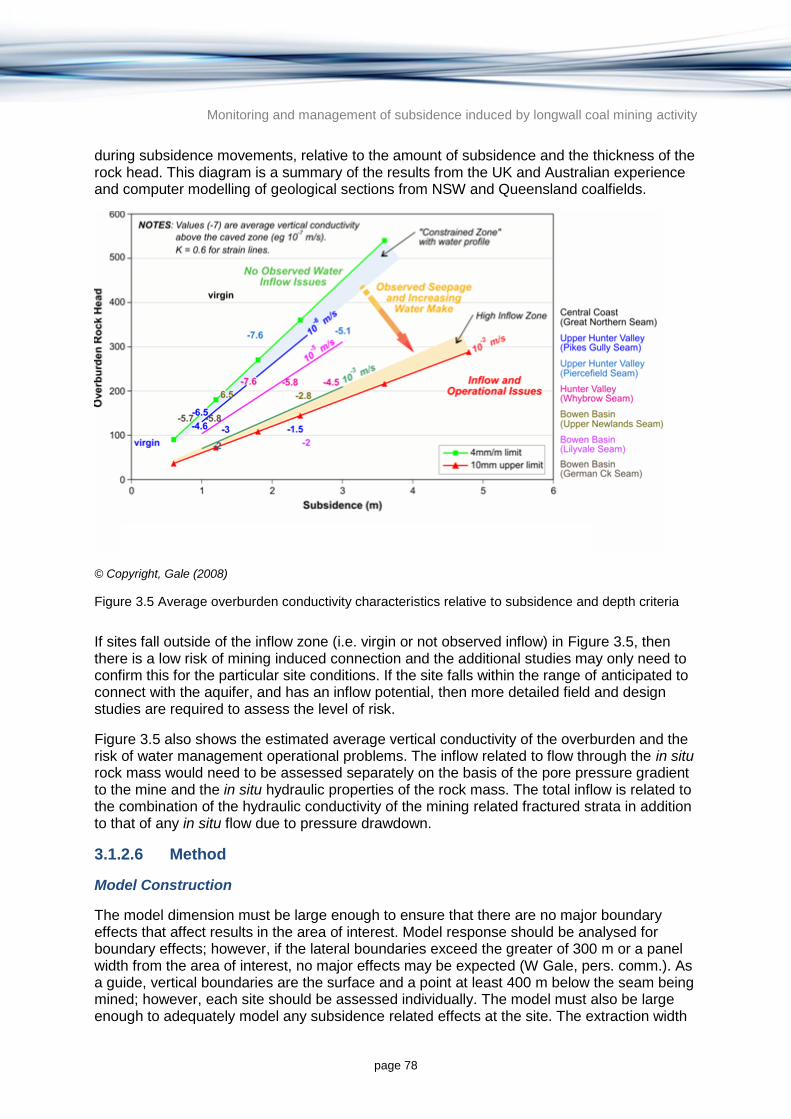
Monitoring and management of subsidence induced by longwall coal mining activity
page 78
during subsidence movements, relative to the amount of subsidence and the thickness of the rock head. This diagram is a summary of the results from the UK and Australian experience and computer modelling of geological sections from NSW and Queensland coalfields.
© Copyright, Gale (2008)
Figure 3.5 Average overburden conductivity characteristics relative to subsidence and depth criteria
If sites fall outside of the inflow zone (i.e. virgin or not observed inflow) in Figure 3.5, then there is a low risk of mining induced connection and the additional studies may only need to confirm this for the particular site conditions. If the site falls within the range of anticipated to connect with the aquifer, and has an inflow potential, then more detailed field and design studies are required to assess the level of risk.
Figure 3.5 also shows the estimated average vertical conductivity of the overburden and the risk of water management operational problems. The inflow related to flow through the in situ rock mass would need to be assessed separately on the basis of the pore pressure gradient to the mine and the in situ hydraulic properties of the rock mass. The total inflow is related to the combination of the hydraulic conductivity of the mining related fractured strata in addition to that of any in situ flow due to pressure drawdown.
3.1.2.6 Method
Model Construction
The model dimension must be large enough to ensure that there are no major boundary effects that affect results in the area of interest. Model response should be analysed for boundary effects; however, if the lateral boundaries exceed the greater of 300 m or a panel width from the area of interest, no major effects may be expected (W Gale, pers. comm.). As a guide, vertical boundaries are the surface and a point at least 400 m below the seam being mined; however, each site should be assessed individually. The model must also be large enough to adequately model any subsidence related effects at the site. The extraction width

Monitoring and management of subsidence induced by longwall coal mining activity
page 79
being modelled in detail should be at least 1.6 to 1.7 times the depth, which is usually the dimension at which the ground behaves in a supercritical manner. This may need to be adjusted for deep longwall mines.
Most sites are characterised on the basis of geotechnical or hydrological domains (i.e. volume of rock with generally similar geotechnical rock mass properties). Each domain should be modelled to assess the subsidence and hydraulic conductivity. The choice of domains is typically based on depth, mine panel width, nature of the strata which may influence caving, depth of weathering, aquitards, geological structure, and the nature or morphology of the overlying aquifers.
Grid size should be selected on the basis of suitable simulation of the rock fracture and caving processes. Industry experience to date indicates that elements should be 1 m or less to simulate rock fracture in sufficient detail (W Gale 2013, pers. comm.). Grid size can be increased away from the area of interest; however, mine panels should be simulated using a 1 m grid or less.
Calibration
Geotechnical models need to be validated against real case histories to ensure that the model set up, strata characterisation and material properties are providing a realistic simulation of the deformation process. Computer models being used should have monitored examples either from the site or else examples of back analysis of other sites, to demonstrate the validity of the approach, constitutive relationships and properties used.
The constitutive relationships of rock fracture for particular rock types are relatively consistent and as such there should not be any significant changes from site-to-site. The strength characteristics of the various strata units can vary from site to site and this is reflected in the strata properties within the model for each particular site.
The calibration process should not modify the strength, shear and normal stiffness of the materials significantly outside of the measured properties (or that reasonably estimated on the basis of scale) to match a particular measured subsidence curve. While using unrealistic values of strength, shear and normal stiffness can improve the match of predicted versus observed subsidence levels, the caving process is not well simulated and the model is likely to produce erroneous predictions.
A better approach is to calibrate the model to fit the actual results by varying the nature of some of the strata, such as the degree of bedding or the lateral persistence of certain layers over the area. However, the degree to which these parameters are varied during the calibration process should be within what is likely from a geological sense, and the variation would be minimised where the characterisation of the strata section is detailed and well known.
3.1.2.7 Uncertainty and accuracy
Accuracy of numerical modelling methods is dependent on the approach and ability to estimate appropriate strength characteristics of rock materials (W Gale 2013, pers. comm.). It is not possible to define all rock strength properties and any model is only an estimate based on available properties and experience. The accuracy of modelled behaviour and strength characteristics will be related to the level of detail of the model (and whether it is sufficient to represent the environment being modelled), its ability to simulate realistic rock

Monitoring and management of subsidence induced by longwall coal mining activity
page 80
failure modes, and the adequacy of the material properties gained from rock testing or field monitoring.
Not all modelling codes represent rock failure in the same manner or have the same capabilities to deal with multiple failure modes. Code selection should be done with knowledge of its capabilities and the rock failure mechanics required to be simulated. The modeller should have sufficient knowledge of the mining environment and modelling code to critically assess the adequacy of the output. Inappropriate material properties and modelling code without adequate capability to simulate the rock failure mechanics in a realistic manner will lead to misleading and erroneous results.
In situations where there is scant input data or little or no subsidence data to calibrate against, extreme care should be undertaken when undertaking numerical subsidence modelling. These situations are more amenable to empirical techniques where empirical relationships developed from other sites can be applied to sites with little data (see Section 3.1.1). If numerical modelling is necessary, such as in the situation where subsurface predictions are required, then the results should be given as a guide only and be proceeded with more detailed modelling once more input data is collected.
All modelling predictions need to have a confidence rating or classification. An appropriate method of confidence rating is detailed in the Australian groundwater modelling guidelines (Barnett et al. 2012), which can be adapted for subsidence modelling.
A joint case study was undertaken on subsidence modelling predictions based on data obtained from the Angus Place Colliery in the NSW Western Coalfields. The study demonstrated the variability in subsidence predictions of uncalibrated models due to lack of data. Seven modelling methods were used and generally all overestimated the measured subsidence, particularly at the panel edges (Kay 1990). Both empirical and numerical methods were used during the study including the two-dimensional finite element programs, AFENA, NONLIN, FINELP, the two-dimensional finite difference program FLAC, the two-dimensional discrete element method UDEC, the displacement discontinuity methods MSEAMS (in two dimensions), and MINLAY (in three dimensions) and empirical methods including the Holla DMR method and the empirical program MINESUB (Kay1990). One of the key findings with regard to accuracy was the variability of results with respect to the methods employed and the sensitivity of the model accuracy to the availability of calibration data.
Modification of the material properties is often required to compensate for including details in a model that are not directly supported by data (W Gale 2013, pers. comm.). Extreme care should be exercised because this potentially places a large constraint on the failure pathway of the ground. This approach runs the risk of ‘getting the right answer for the wrong reason’ and should only be used to assess large scale regional or general scenarios which are then re-examined in more detail in a more appropriate model (W Gale 2013, pers. comm.). Such calibration should include not only the maximum magnitudes of subsidence but also the shape and form of the subsidence profile.
3.1.2.8 Case study applications
Tahmoor Mine NSW
A finite difference modelling approach using FLAC software was used to simulate caving and subsidence at Tahmoor Mine in the NSW Southern Coalfield. Actual subsidence was approximately double predicted subsidence by the standard industry empirical approach, so a FLAC model was developed to investigate the difference. Gale and Sheppard (2011) found

Monitoring and management of subsidence induced by longwall coal mining activity
page 81
that the initial 100 m of overburden had been modified by weakening along pre-existing joint and bedding planes adjacent to a deeply incised gorge. Rock testing and detailed characterisation of the site provided the input data for the model. The model was able to simulate typical caving and subsidence characteristics away from the modified zone near the gorge, together with the behaviour affected by the gorge. The site provided excellent validation for the method and the approach used to simulate caving and subsidence around longwall panels.
ACARP project C13013
Gale (2008) described a study of the potential for inflow from water sources above longwall panels in coal mines. The study included mines in NSW and Queensland and numerical modelling of the caving and subsidence characteristics of a number of sites was undertaken. Validation of a number of sites was undertaken and provided a high level of confidence in the modelling approach and outputs from the models. A key outcome from the study was that fracturing and subsidence could be related to groundwater flow networks established in the fractured overburden above the longwall panels. Model results compared well with measured data, which provided confidence in the approach.

Monitoring and management of subsidence induced by longwall coal mining activity
page 82
3.1.3 Summary of subsidence modelling methods
Table 3.3 provides a summary of the main empirical and numerical modelling methods available to predict subsidence based on information presented in Sections 2 and 3.
Table 3.3 Summary of subsidence modelling methods
Method type
Method Method description Inputs Outputs Situations most suited Use in Australia Accuracy
Empirical methods
Holla DMR method (e.g. Holla & Barclay 2000)
Modified from a technique developed by the British National Coal Board. Details and methods for predicting subsidence are contained in three handbooks for the NSW Southern, Newcastle and Western Coalfields.
panel widths
chain pillar widths
average cover depth
average seam thickness
Over a single panel or longwall, or a series of longwall panels:
maximum subsidence (Smax)
maximum compressive strain
maximum tensile strain
maximum tilt
maximum hogging curvature
maximum sagging curvature
NSW Southern, Western and Newcastle Coalfields
Greenfield sites where mine layouts are not yet known and where a worst case scenario prediction is required
Generally NSW Coalfields.
This method has largely been superseded by the IPM.
Similar to the IPM for maximum subsidence predictions in cases where the panel widths and cover depths are within the ranges that were used to develop the method (MSEC 2003). Data was generally obtained from narrower longwall panels than are currently mined and the depth of cover range was limited for each coalfield by data availability.
Ditton and Frith (2003) method
Enables the influence of massive strata units, such as conglomerate and sandstone channels, chain pillar compression and regional structure to be included in predictions over single and multiple longwall and miniwall panels.
mine layout
panel widths
cover depths
seam working heights
rock mass density
rock mass strength (unconfined compressive strength)
rock mass stiffness (Young’s modulus)
Poisson’s ratio
strata units
location of strata units above the workings
maximum subsidence (Smax)
panel goaf edge subsidence
AoD
maximum transverse and longitudinal tilt
curvature
horizontal displacement and strain
locations of the above parameters
Newcastle Coalfield
Only suited to single coal seams
Predominantly used in the Newcastle Coalfield, but also in some Bowen Basin mines in Qld.
Reasonable results in most cases where reviewed by MSEC (unpublished reports in the Newcastle Coalfield; A Waddington 2013, pers. comm.).
Influence function method (e.g. Kay et al. 2011)
Uses calibrated functions against measured site-specific data to predict subsidence. The method produces grid points enabling surface modelling of various subsidence related parameters.
(minimum requirements)
angle of influence
maximum subsidence (Smax)
edge effect
location of inflection point
cover depth
maximum subsidence (Smax)
tilts
curvatures
strains
horizontal movements
These outputs can be presented in any arbitrary direction. All output can be
Landscapes with existing survey data, characterised with flat or gently sloping topography rather than areas of large topographic relief such as valleys.
Limited use but has been applied in some NSW coalfields.
Validation of accuracy has not been well studied.
Uses the same method of calibration as point and profile methods, which have been suggested to have an accuracy of within 10 per cent for vertical subsidence.
Accuracy of tilt and strain predictions has not been established.

Monitoring and management of subsidence induced by longwall coal mining activity
page 83
Method type
Method Method description Inputs Outputs Situations most suited Use in Australia Accuracy
represented as gridded surfaces enabling visualisation of predictions.
Incremental profile method (IPM)
Defines the characteristic shape for each increment of vertical displacement resulting from a mining operation, based on previous field measurements. Once the vertical displacement profile has been created, it can be used to predict the displacement resulting from hypothetical mining scenarios.
As much information as possible on local conditions to allow calibration including:
mine layout plans
seam level contours
surface level contours
seam working heights
proposed mining sequence
the speed of mining
the lithology of the overburden
typical borehole data
local subsidence survey data from previously mined areas.
At any point across the mining area:
surface subsidence (including Smax)
tilts
curvatures.
Areas that are geotechnically similar to the empirical data upon which the technique is based.
Can also be applied in areas where there is local data to calibrate against:
mines where subsurface subsidence predictions are required
areas of irregular pillar extraction
multiple mining seams.
Coalfields in NSW and Queensland. Currently the most widely used subsidence modelling technique in Australia.
There is a higher probability of exceedance for Bowen Basin mines (15 per cent) relative to NSW mines (10 per cent).
Predictions are skewed towards a conservative over-estimate of maximum subsidence.
SRMS errors suggest that accuracy in the Bowen Basin is similar to the NSW coalfields despite the empirical relationships being largely determined from NSW examples.
Accuracy is greatly improved by calibrating with local subsidence data.
ACARP method
(ACARP 2002; Kay et al. 2011)
Predicts valley related movements based on an extensive database from coal mining operations in NSW. The method can estimate valley wall closure and floor upsidence in gorges, river valleys, creek alignments and other watercourses.
incremental subsidence of the panel or longwall that is being mined
valley depth
distance from side and end of longwall.
predicted upsidence
predicted valley closure
predicted compressive strain at a point in a valley.
Prediction of valley related mining induced movements.
More relevant for mining operations in the Southern Coalfield, but can be used with caution in other areas.
Should be calibrated to local data where possible.
NSW coalfields Conservative method generally over-predicts movements.
Probability of exceedance is approximately 5 per cent.
Numerical methods
Finite element (e.g. Plaxis)
Plaxis 2D is used to model a plane strain and axisymmetric models while Plaxis 3D has capability to simulate a three-dimensional model.
Young’s modulus at various axial stress values during pre- and post-failure
Poisson’s ratio
dilation angle
tensile strength of rock and bedding planes
cohesion and friction angle
fractures and bedding at various confining pressures pre- and post-failure
rock fracture model and its orientation within each modelling element or cell.
normal and shear stress in each element
horizontal and vertical displacements in each element
dilation and strain within the strata.
sites where the height of fracturing, caving characteristics or changes in aquifer permeability are required (not possible with empirical techniques)
sites where the geotechnical conditions are substantially different from empirical data
sites where there are substantial geological structural issues such as joints and fractures
sites where multiple coal seams are being mined
not suited to sites where
NSW and Queensland
Accuracy will be related to:
the level of detail of the model
its ability to simulate rock failure modes
the adequacy of the material properties used as input.
Numerical models can be very sensitive to calibration and the correct selection of model type to suit expected caving conditions, and accuracy generally improves with increasing data availability (Kay 1990).
As models increase in complexity, the level of accuracy can decrease if data is not available to support the added complexity (Kay 1990).
Finite difference (e.g. FLAC)
FLAC enables simple simulation of progressive failure and progressive excavation.

Monitoring and management of subsidence induced by longwall coal mining activity
page 84
Method type
Method Method description Inputs Outputs Situations most suited Use in Australia Accuracy
shear and normal stiffness of joints
partings within the strata
hydraulic conductivity of the strata.
prediction of anomalous movements is required.
Sometimes used to provide inputs to empirical techniques (e.g. IPM) such as in greenfield sites where a weak roof or floor can result in further settlement in the pillar region which is not readily predicted by empirical techniques (A Waddington 2014, pers. comm.).

Monitoring and management of subsidence induced by longwall coal mining activity
page 85
3.2 Groundwater modelling methods
Groundwater modelling techniques are described in a number of texts (e.g. Anderson & Woessner 1992) and currently accepted best practice in Australia is defined by Barnett et al. (2012).
Predicting impacts on groundwater resources from longwall subsidence usually involves initial numerical subsidence modelling to determine changes to aquifer hydraulic properties followed by numerical groundwater modelling to determine the impacts on groundwater levels and quality. Numerical subsidence modelling techniques are favoured over empirical methods because of their ability to simulate subsurface deformation and changes to aquifer hydraulic properties (refer to Section 3.1.2 above and an example approach is given in Gale (2008)).
This section summarises the modelling methods available for predicting the impact of longwall coal mine subsidence on groundwater and the specific challenges that must be considered when applying numerical groundwater modelling techniques to longwall mining problems. Specific features of longwall coal mines that must be addressed in a typical groundwater flow modelling investigation include:
temporal changes in hydrogeological parameters in the mine, goaf and overlying formations due to rock deformation, fracturing, subsidence and compaction that accompanies the collapse of longwall panels
inflows to the longwall panels during mining operations when the panels are dry and pressures are reduced to atmospheric. This condition is often maintained with a saturated zone above the mine, leading to the formation of two distinct water table conditions; one near surface perched water table and the other at the base of the mine void and separated by a zone of desaturation
inclusion of walls or barriers in the mine to control water movement and to provide structural support during mining
modelling the void during excavation, mining and collapse.
Both finite difference and finite element modelling codes can be used to simulate groundwater response to subsidence arising from longwall mining. Of many available models, two have been commonly used that include the features and capabilities required to adequately represent the groundwater stresses and groundwater responses to the types of stress that accompany longwall mining; FEFLOW and MODFLOW with the SURFACT add-on. Both options are similar in terms of ease of use, cost, input data required, control of accuracy and suitability for longwall mining problems, so these aspects are discussed together below.
3.2.1 Finite element approach (FEFLOW)
FEFLOW is a numerical simulation code used to model the movement of water, solutes and heat in porous and fractured media (Diersch 2006). FEFLOW is perhaps the most commonly used finite element simulation code in the groundwater industry. It contains a number of features that make it suitable for modelling the groundwater related impacts associated with longwall mining activities. In most situations FEFLOW is able to incorporate or address all specific features required for simulating the impacts on groundwater from longwall coal mine subsidence. The software has basic functionality that includes the ability to implement dynamic changes in hydrogeological properties during the course of a model run. When run with the unsaturated zone option, it is able to replicate two coincident water table conditions and the finite element formulation provides a means of replicating complex geometric arrangement of panels, walls and barriers constructed during the mining operation.

Monitoring and management of subsidence induced by longwall coal mining activity
page 86
3.2.1.1 Advantages and disadvantages
Advantages of the FEFLOW modelling code are listed below.
The triangular finite element formulation provides a basis for developing a numerical calculation mesh that accurately replicates complex natural features (such as river beds, drainage lines and faults) and mine features (such as the panels, walls and barriers). In this regard, FEFLOW has a significant advantage over commonly used finite difference codes such as MODFLOW that require the use of a rectangular grid structure. However, it is noted that the recent development of a finite volume version of MODFLOW (MODFLOW USG) allows increased flexibility in the grid structure and element shapes and these features will make it more attractive in the future when it is implemented in the commonly used graphical user interfaces.
FEFLOW has basic functionality that allows the implementation of time-varying hydrogeological properties (i.e. hydraulic conductivity, specific yield and specific storage) as required to model the hydrogeological impacts of subsidence that occurs during longwall coal mining.
The availability of a ‘seepage face’ boundary condition is suitable for replicating the flow of groundwater into the mine void.
FEFLOW is able to replicate the development of a deep water table and an unsaturated zone in the mining cavity with an overlying saturated zone and shallow water table (J Mayer 2012, pers. comm., 20 August)6.
Disadvantages of the FEFLOW modelling code are listed below.
It is not as widely used in Australia as MODFLOW and hence, the use of FEFLOW may limit the number of modellers able to develop or use the model.
Full implementation of time varying boundary conditions (and boundary constraints) and time varying material properties together with the unsaturated zone option often results in short time steps required for numerical solution so model run times can be excessive and model output files can be large.
Implementation of parameter estimation software such as PEST (PEST 2015) is not as advanced in FEFLOW as in some Graphical User Interfaces (GUIs) used with the MODFLOW code. The use of advanced uncertainty analysis is not part of the basic functionality available in the FEFLOW code.
3.2.2 Finite difference approach (MODFLOW-SURFACT)
MODHMS is a fully integrated surface water/groundwater flow code developed by HydroGeoLogic Inc. (HydroGeoLogic 1996). MODFLOW-SURFACT is the subsurface component of MODHMS and is discussed in this section. The groundwater flow module is based on MOFLOW, the U.S. Geological Survey modular three-dimensional groundwater flow modelling code (McDonald & Harbaugh 1983).
MODFLOW uses a block-centred finite difference approach to simulate groundwater flow. Fully or quasi three-dimensional simulations of confined and unconfined layers may be performed. MODFLOW-SURFACT solves three-dimensional saturated/unsaturated subsurface flow equations or alternatively solves equations for performing unconfined
6 Mayer, J (DHI-Wasy technical support to B. Barnett of SKM).

Monitoring and management of subsidence induced by longwall coal mining activity
page 87
simulations to rigorously model de-saturation/re-saturation of layers to overcome numerical difficulties encountered with previous versions of MODFLOW (HydroGeoLogic 1996).
Features of MODFLOW-SURFACT of particular relevance to simulating impacts from mining induced subsistence are the adaptive time-stepping and output control procedures, an additional preconditioned conjugate gradient solution package, a Newton-Raphson linearisation package for improved robustness and a package for allowing time varying material properties.
Like FEEFLOW, in most situations MODFLOW-SURFACT is able to incorporate or address all of the specific requirements for modelling the impact of longwall coal mining on groundwater resources and has basic functionality that includes the ability to implement dynamic changes in hydrogeological properties during the course of a model run. When run with the unsaturated zone option it is able to replicate two coincident water table conditions. The finite difference mesh along with the MODFLOW horizontal flow barriers package can represent complex geometric arrangement of panels, walls and barriers constructed during the mining operation.
3.2.2.1 Advantages and disadvantages
Advantages of the MODFLOW-SURFACT modelling code include:
It does not require a pre-processor or interface software package to run the program. This can potentially provide cost savings over other platforms and allow distributive computing with reduced licensing requirements.
It has basic functionality that allows time-varying hydrogeological properties (hydraulic conductivity, specific yield and specific storage) to model the impacts of subsidence that occur during longwall coal mining. This provides a convenient method of simulating the life of mine in a single model run.
A basic drains package and a ‘seepage face’ boundary condition are available, which are suitable for simulating flow into the mine void.
Several unsaturated zone options are available to provide various levels of detail in replicating the unsaturated zone in the mining cavity with an overlying saturated zone and shallow water table.
MODFLOW—and by association MODFLOW-SURFACT—is the most widely used three-dimensional groundwater modelling platform and there is a broad level of understanding and familiarity across industry and government sectors.
Implementation of parameter estimation software such as PEST is fully compatible with MODFLOW-SURFACT and in some GUIs. Advanced uncertainty analysis is part of the basic functionality.
Disadvantages of the MODFLOW-SURFACT code include:
Full implementation of time varying boundary conditions (and boundary constraints) and time varying material properties together with the unsaturated zone option can:
− require short time steps for a numerical solution
− extend model run times
− create large model output files.
The block-centred finite difference method is not particularly flexible or adaptable for representing complex geometries such as mining panels and underground structural components. Care needs to be taken to choose an appropriate grid size and orientation to

Monitoring and management of subsidence induced by longwall coal mining activity
page 88
best replicate mine plans while at the same time not creating unnecessarily large output files and long simulation times.
3.2.3 Ease of use and cost
As with all numerical simulation codes the ease of use depends on the familiarity of the modeller with the particular code. Both FEFLOW and MODFLOW-SURFACT are no different in that modellers need to learn the full capability and features of the software and become familiar with the GUI before the code can be used efficiently.
For experienced users there is probably little difference in the time or effort required to formulate and run a FEFLOW or MODFLOW-SURFACT model. The formulation of a FEFLOW calculation mesh (or grid) can be more complex and time consuming because it has more flexibility and capacity to represent complex spatial geometries7.
There is little difference between the costs of a FEFLOW license compared to MODFLOW with the SURFACT add-on. However, if MODFLOW is used without a commercial GUI then substantial savings in software licenses may be realised.
3.2.4 Situations most suited
Both FEFLOW and MODLFOW-SURFACT are suited to modelling the flow of groundwater into longwall coal mines during and after mining. They can represent changes in hydrogeology in and around the mine that occurs as the mine cavity collapses and the geological formations above the mine are stressed and deformed. They are ideally suited to estimating mining related impacts on groundwater and associated environmental assets that rely on groundwater.
3.2.5 Data needs (inputs)
Groundwater models developed to assess the impacts of subsidence arising from longwall coal mining are no different from any other groundwater models in terms of the required data, and in general require the following datasets:
rainfall records
evaporation measurements or estimates
measured groundwater heads (expressed as elevations), preferably as a time-series
terrain model of the ground surface
river course locations
river flow records including stage heights expressed as elevations and estimates of baseflow contribution
groundwater extraction records
groundwater licenses in the region (for approximations if groundwater extraction records are incomplete)
surfaces that define the boundaries between overlying hydrostratigraphic units
pumping test data, interpretations and analyses
7 Until the MODFLOW USG code has been successfully implemented in the commonly used graphical user
interfaces the level of effort required to build, run and process results in MODFLOW USG will significantly exceed that of the other codes.

Monitoring and management of subsidence induced by longwall coal mining activity
page 89
land use maps.
Additional datasets specific to modelling longwall coal mines include:
historic mine operations including a definition of the spatial progression and growth of the mine
changes in measured groundwater levels in response to past mining
changes in baseflow in response to past mining
quantitative estimates of historic changes in hydraulic conductivity, specific yield and specific storage that have occurred as a result of past mining
future mine plans including the spatial growth of the mine and the spacing and orientation of walls and barriers constructed in the void
estimates of future changes (both in time and location) of hydraulic conductivity, specific yield and specific storage that will occur as a result mining and associated collapse of the void.
3.2.6 Modelling method
3.2.6.1 Model design and construction
The model design and construction is the process of adapting the hydrogeological conceptualisation to a numerical modelling framework. The process involves the selection of the software tools that are most appropriate for the particular geological setting and mine plan. It also involves definition of the size and spatial discretisation of the model domain, the temporal discretisation to be used for transient models, and the boundary conditions that will be used to define various features of the hydrogeological environment and the mining operations.
In most cases it is expected that groundwater models of longwall coal mines will be constructed in three dimensions. In general, it will be necessary to use three dimensions to fully represent the mine itself and the groundwater movement that will occur in and around the mine. However, there may be certain circumstances when it may be possible to represent the mining activities, subsidence and associated impacts in a two-dimensional model. In these cases it is assumed that the model would be oriented within the vertical plane so that fracturing and deformation associated with subsidence can be represented through changing hydrogeological parameters in the vertical plane.
A two-dimensional modelling approach may be appropriate if the mine geometry can be represented by a series of parallel slices through the mine and the environmental assets of particular interest. Similarly, a two-dimensional radial flow model (using a radial arc of known angle) may be appropriate where such slices are representative of significant portions of the mine.
3.2.6.2 Temporal discretisation
In many instances models will be required to be developed in transient mode for both calibration and predictive analysis. In general, it is expected that the role of steady state models in longwall coal mining applications will be limited to the model calibration phase and it is unlikely that steady state models will be appropriate for predictive scenarios. The changes that are likely to occur during mining are in most cases transient in nature and the use of a transient modelling approach will be required to simulate these changes.

Monitoring and management of subsidence induced by longwall coal mining activity
page 90
For transient calibration models, the temporal discretisation should be chosen so that seasonal variation in climate (and possibly groundwater pumping) over the calibration period can be adequately captured in model input datasets. For the predictive scenarios, the temporal discretisation should be sufficient to allow the mine development plan to be adequately represented. In both cases it is not necessary to incorporate a constant increment in stress periods and these can be tailored to match the time varying nature of the stresses being modelled.
3.2.6.3 Confidence level classification
The model confidence level classification is a cornerstone concept of the Australian groundwater modelling guidelines (Barnett et al. 2012). It provides a means of classifying models according to the level of confidence with which they can be used in predictive mode. The classification depends on a number of factors including the amount and quality of data from which the conceptualisation can be developed and on which calibration is based, the manner in which the model has been calibrated and the manner in which the predictive scenarios have been formulated.
The classification provides an agreed target that the modellers endeavour to achieve through the course of a modelling project. While the target classification level will depend on the confidence level that is desired or indeed required of the model, it may also reflect the practical constraints associated with data availability. To this end, there may be a need to define a staged approach to model development in which the initial target confidence level is relatively modest (e.g. reflecting a lack of available data) with later stages of the modelling aimed at higher confidence levels to meet requirements of regulators and mine owners. The model confidence level classification plays a number of important roles in the development, use and assessment of groundwater models of longwall coal mines (listed below).
The agreed confidence level classification target defines a level of rigour and complexity required in the calibration and validation processes and in the model design
The agreed confidence level classification provides an indication of the appropriate uses of the model. For longwall coal mines, high confidence level classifications (Classes 2 and 3) are required for those mines that exhibit a high risk profile as might result from mines that have a high probability of generating significant impacts or where the consequences of any impacts are considerable. Conversely, mines with a low risk profile may be modelled with lower confidence levels. Determination of an appropriate target confidence level classification will depend on the outcomes of the initial qualitative risk assessment (refer to Section 5.3).
In reviewing the model, the reviewer should assess whether or not the agreed confidence level classification has been attained. This will involve a number of quantitative and qualitative criteria that the reviewer considers appropriate (guidance on these criteria is provided in Barnett et al. (2012)).
There are a number of issues specific to longwall mining developments that should be considered when evaluating the confidence level classification (listed below).
As a general rule, it is considered appropriate that the existence and operation of longwall mines in neighbouring areas should provide validation of the model and its predictive outcomes and hence, should reduce the uncertainty of predictive models. It is particularly relevant where the operational details of neighbouring mines and the measurements of subsidence and associated water resource impacts are available for developing conceptual models and for validating both the subsidence estimation and the water resource impacts model. Where there are neighbouring mining operations, models should

Monitoring and management of subsidence induced by longwall coal mining activity
page 91
be designed to both illustrate the probable incremental impact of the proposed mining operation and should also consider the cumulative impacts of the mine together with all other nearby operations.
In most instances, the calibration of a groundwater model developed for a new or planned mine will utilise groundwater level data collected prior to the start of mining activities. This is likely to be restricted to water level observations in bores drilled by the mining company that will likely span a relatively short time frame compared to the time of proposed mining. The length of any transient calibration in relation to the length of prediction is an important criterion used in assessing the confidence level classification. As such, models developed for new or planned mines are likely to rate poorly in such criteria unless additional monitoring data is available from adjacent or nearby bores in other tenements.
Calibration of a groundwater model designed to assess the water resource impacts of a greenfield longwall coal mine is likely to be constrained to a steady state approach based on pre-mining groundwater observations coupled with a short-term transient calibration undertaken prior to the start of mining. Accordingly, the level of stress incorporated in calibration models (in this case groundwater extraction and deformation related to subsidence) is likely to be small relative to those that will occur during mining. This will also result in a poor rating in terms of criteria related to the level of stress in calibration compare to that in prediction.
It is unlikely that a groundwater model of a greenfield longwall coal mine will attain a Class 3 classification (highest confidence level ranking) before mining starts. This is simply due to the fact that the area will not have been subject to the stresses that are likely to arise from mine induced subsidence and hence, it will not be possible to demonstrate the model’s ability to replicate aquifer responses to subsidence. In many instances, it will be necessary to improve confidence in model predictions and hence, it may be necessary to undertake post-model validation (post-model auditing) once mining and associated subsidence is initiated. Through this process, the confidence in model predictions can be progressively increased and eventually elevate the model ranking to Class 3. The process relies on gaining initial approvals for mining that may be based on a model that has a confidence level ranking lower than desired. Accordingly the value of engaging with environmental regulators in the planning and design stage of a modelling exercise cannot be understated.
3.2.6.4 Implementing changes due to subsidence
Subsidence and deformation of the rocks above the mine must be implemented in the groundwater model through changes to the hydrogeological parameters that describe the transmission and storage capacity of the hydrogeological units included in the model. These changes can be implemented seamlessly through the use of the time varying material properties menu in FEFLOW or through the TMP module of MODFLOW SURFACT. Both of these features allow for the change in hydraulic conductivity, specific yield and specific storage to be scheduled as part of the model input. The same changes can be implemented in a step-wise manner in MODFLOW or FEFLOW by creating a series of sequential model runs in which an individual model with constant hydrogeological parameters is created for each individual stress period. The ‘model’ is then run as a sequence of all individual models with the initial conditions for each step obtained from the final conditions of the previous step. This modelling approach is feasible but is labour intensive to set up and run and experience has shown that an automated approach to changing material properties is preferred.
The changes to the rock properties arising from the mining activities and associated subsidence are best obtained from subsidence models described above (refer specifically to

Monitoring and management of subsidence induced by longwall coal mining activity
page 92
Gale’s (2008) empirical approach that can be used to convert predicted subsidence to changes in hydraulic properties of the geological units above the coal seams). These changes may be provided in the form of absolute values of hydraulic conductivity at various times and locations in the model or they may take the form of multipliers on the existing or pre-mining properties of the geological units in the mine and its surroundings. In addition to the estimated changes in hydraulic conductivity that may occur as a result of subsidence and rock deformation it may also be necessary to include changes to groundwater storage parameters. In particular the growth and migration of the working mine should be reflected in the scheduling of time varying storage parameters assigned to the coal seams that are mined. At times when the coal is removed from the seam and the mine is an open cavity, the specific yield should be set to a value of one. This parameterisation is appropriate for the simulation of a cavity as a specific yield of one indicates that for every meter rise or fall in head one cubic meter of water is gained or lost to storage per square meter of model area. For all practical purposes, if the cavity is dry (as is the case when it is being mined) then the potentiometric surface will be at or below the floor and the specific yield of the cavity will not directly influence groundwater movement or storage. However, at times when mine dewatering is interrupted or ceases completely (e.g. at the completion of mining), any remaining cavities (often created in overlying units due to collapse of the longwall panels) will fill with water and the assigned specific yield will play an important role in the predicted transient groundwater responses.
3.2.6.5 Implementing mine dewatering operations
In addition to the changes associated with subsidence, the model must also account for and simulate the effects of the removal of water that enters the mining cavity. This is best simulated through the implementation of time varying head dependent boundary conditions assigned to that part of the mine that is open and dry. This approach will result in substantial temporal variations in mine inflow rates being estimated by the model. This effect is caused by the need to specify the variations in the head dependent boundary condition in discrete stages. As the mine progresses, head dependent boundary conditions representing the dry mine cavity will be moved from one set of cells (appropriate for model stress period x) to another set of cells (appropriate for stress period x+1). The instantaneous application of a constant head condition on the mine cavity cells will cause a rapid inflow of water to these cells calculated immediately after the boundary condition is applied. The estimated inflow rates will subsequently decay over the remainder of the stress period. The resultant instability in inflow rates are artefacts of the modelling process. Rather than reporting these strongly variable inflow rates in which there is a regular and often dramatic peak calculated at the start of each stress period, it is often appropriate to average the calculated inflow rates over each stress period. In this way, a smoother, more realistic transition in inflow rates will be presented.
3.2.6.6 Surface water and groundwater interaction
In some circumstances the subsidence impacts on groundwater will give rise to changes in the interaction between groundwater and surface water in the region of the mine. These changes may arise from:
increased flow of water from rivers, lakes and wetlands to groundwater in response to subsidence and associated falling groundwater levels above the mine as the panels collapse. This phenomenon will lead to a reduction in baseflow in rivers and streams that drain the mined region
increased groundwater discharge to rivers, lakes and wetlands as groundwater levels rise during the recovery phase following the collapse of the longwall panels. As the disturbances caused by subsidence diminish, a recovery towards pre-mining groundwater
Monitoring and management of subsidence induced by longwall coal mining activity
page 93
levels may be expected. At this time, an increase in groundwater contribution to river flow may occur.
Where the mine is located in close proximity to important surface water resources it will be necessary to include surface water-groundwater interactions in the groundwater and surface water models. In this regard, the modelling approach is no different to any other development that impacts groundwater.
Barnett et al. (2012) provides useful guidance on the different approaches that can be used to assess the dynamic interaction between surface waters and groundwater. In general, there are three different alternatives to model the processes.
Inclusion of appropriate boundary conditions in the groundwater flow model (e.g. MODFLOW river boundary conditions using the RIV or STR packages or the FEFLOW Transfer Boundary Condition) using assumed, averaged or measured river stage elevations.
Non-dynamic linking of the groundwater model to a surface water model in which the surface water model is used to provide the heads for the groundwater model at the locations where the two models intersect. In this case, the surface water model is run over the period of interest. The predicted stage elevations are then used to define heads in the groundwater flow model boundary conditions of the type described above. Under some circumstances there may be a need to export the predicted fluxes into and out of the groundwater model boundary conditions to use as an input to a repeat run of the surface water model.
Full dynamic coupling of the groundwater and surface water models. This approach requires a software code that can run both the surface water and groundwater models concurrently. Model predicted data are exchanged between the two models during the model run.
Barnett et al. (2012) provides the following advice when considering which approach is appropriate:
‘A modelling approach based on linking or coupling surface water models to groundwater flow models should be used when surface water dynamics are significantly affected by exchange flows. When surface water dynamics are likely to be unaffected, or only slightly affected, an approach based on groundwater flow modelling with standard boundary conditions may be adequate.’
© Copyright, Barnett et al. (2012)
A further important consideration that is applicable to longwall coal mine models that include the impacts of subsidence is that the surface water dynamics may be strongly influenced or changed by the subsidence caused by the mining operations. To this end, it may be necessary to include the impacts of subsidence on the surface water model as part of the modelling process. In some cases the changes in surface water flow may well include a change in the geometry of the wetted surface. Subsidence may lead to overbanking and inundation of large areas of land that would otherwise be dry. In this case, the groundwater model may need to be modified to account for the changes in the area within which the groundwater model interacts with surface waters.
Where a particular river, stream or lake is located in a heavily developed mining province, surface water and groundwater interaction models will usually need to address both the incremental impact of a particular mining operation and the cumulative or combined impacts of
Monitoring and management of subsidence induced by longwall coal mining activity
page 94
all mines and other human activities that contribute to the interaction between surface water and groundwater.
3.2.6.7 Inclusion of climatic stresses
While the combined influences of groundwater recharge and evapotranspiration may be important stresses in the pre-mining environment and hence, may be important features of the pre-mining models, they are relatively insignificant when compared to the groundwater stresses that are introduced once mining and associated subsidence occurs. This point reinforces the considerations raised in Section 3.2.6.3 in that the confidence level associated with model predictions are generally low if the model has not been calibrated or validated by matching predicted groundwater responses to those measured during mining operations. It also suggests that focussing on developing a complex and accurate representation of recharge and evapotranspiration stresses may not be warranted in all cases.
3.2.6.8 Calibration
Model calibration is used to refine the hydrogeological parameters included in the model to define the transmission and storage of water in the rocks and sediments represented in the model. The calibration process plays an important role in the determination of the confidence level classification as discussed in Section 3.2.6.3. For groundwater models aimed at assessing the impacts of subsidence arising from longwall coal mining operations, the crucial calibration issue is whether or not the model can be validated by matching modelled outcomes to measured or observed responses to subsidence in historic mining operations. In other words, if it can be demonstrated that the model can reproduce the subsidence related responses that have occurred in the past then it has far more credibility than one that has yet to demonstrate this capability.
The following paragraphs illustrate typical calibration methods that are applicable to longwall coal mining applications. Barnett et al. (2012) has a more extensive discussion on the topic as applicable to groundwater models in general.
A steady state calibration should be attempted in most modelling instances. The underlying steady state assumptions will often lead to some uncertainty due to the fact that few groundwater systems are truly stable and most will exhibit seasonal fluctuations together with longer term trends in groundwater heads and fluxes. The benefits of a steady state calibration are that the data requirements are generally less imposing than for transient calibration. Also, the pre-mining steady state model result provides appropriate initial conditions for any subsequent predictive model runs aimed at investigating the changes that will accompany the introduction of a longwall coal mining operation.
In general, an appropriate transient model calibration will contribute to the confidence level of the predictive models more than a steady state calibration. This inference largely arises from the fact that a transient calibration will, in many instances, illustrate the model’s ability to replicate groundwater responses arising from stresses of a similar form to those included in the predictive model runs. Transient calibration also provides a means of constraining the model parameters that define the storage potential of the rocks and sediments included in the model, whereas a steady state model solution is insensitive to storage parameters.
As discussed above, a transient calibration that involves stresses derived from actual mining operations is desirable and significant in terms of the confidence level classification. The duration and magnitude of the stress conditions included in the transient model have a significant bearing on the confidence level classification of the model and care should be taken

Monitoring and management of subsidence induced by longwall coal mining activity
page 95
in planning a transient calibration exercise to address the relevant criteria (refer to Table 2.1 of Barnett et al. 2012).
The following issues should be considered:
a Class 3 model confidence level can only be attained if the model has been calibrated using measured groundwater responses to subsidence that has occurred at or near the mine site due to historic longwall mining operations
in greenfield sites where there are no existing longwall coal mines, the highest confidence level likely to be achieved is Class 2. In this case, the model should be calibrated to long-term transient data obtained from monitoring sites located in the model domain
in the case of little or no long-term monitoring data at the site, a transient model calibration will not be feasible and the model would likely be considered as a Class 1 model
where calibration methods are restricted by the available data, ongoing model validation should be undertaken so that the model confidence level can be upgraded as more detailed information is attained.
3.2.6.9 Predictive scenarios
The changes that occur due to subsidence in a longwall coal mine are expected to be strongly time variant. Accordingly, predictive model scenarios should be run in transient mode. The models will typically be run for the duration of mining operations and for some period following mining to assess the groundwater behaviour following mine closure. Care should be taken to select an appropriate stress period for predictive scenarios. In many cases it may be appropriate to select a variable stress period that best fits with the details of the mine development plan.
As a general rule, the smaller the model stress period, the smaller the temporal variation in estimated inflows to the mine. As discussed in Section 3.2.6.5, the use of head dependent boundary conditions to induce flow into the mining cavity will lead to temporal variability with strong peaks in inflow rate being predicted at the start of each stress period. The temporal variability can be reduced by employing a smaller stress period. Alternatively, averaging the inflows over each stress period will provide a more subdued temporal variability in inflow estimates. The smoothed or averaged results are, in most cases, more realistic than the raw model results that show strong temporal variability within each stress period. This is because the variability is largely due to the instantaneous changes in mine area and depth assumed by the model at the onset of each stress period when in reality the mining will grow and migrate in a more steady progression.
The impacts that are typically of interest, and that the model is designed to assess, are best obtained by running two models (one with and one without the mining operation) with the results presented as the difference between the two model runs. The model results of particular interest usually include:
the changes in groundwater head in aquifers in which there are existing groundwater users. Such outcomes are best illustrated as a time-series plot of heads at the locations of groundwater users. Alternatively, maps of drawdown in groundwater head can be presented at various times during the life of the mine and following mine closure
changes in baseflow to rivers and lakes located within the model domain. Time-series results are generally extracted from the boundary conditions that define the model’s interaction with surface water bodies

Monitoring and management of subsidence induced by longwall coal mining activity
page 96
the inflows to the mine during and after mining operations
impacts on GDEs can be illustrated as a change in the modelled evapotranspiration. Here it is assumed that any loss of evapotranspiration predicted by the model (i.e. reduction in evapotranspiration caused by a decline in groundwater heads in areas of shallow water table) can be considered as the potential loss of water available to GDEs. The results can be further illustrated by the presentation of water table drawdown maps that show the difference in water table elevation caused by the mining operation. Such maps will help illustrate the locations where near surface impacts are expected.
3.2.6.10 Uncertainty analysis
Experience suggests that there is no single ‘true’ model that can predict groundwater responses with absolute accuracy. All models include underlying uncertainty and understandable reporting of uncertainty provides necessary context to decision makers. Given that the consequences of management decisions vary, it follows that the extent of and resources devoted to an uncertainty analysis should depend on the risk of making a decision based on an erroneous model outcome and the associated consequences that may arise from that decision. For events with low potential impact, a qualitative, limited uncertainty analysis may be sufficient for informing a decision. On the other hand, for events with a high impact, the risks might be better assessed and associated decisions made using a more robust and comprehensive uncertainty analysis (Barnett et al. 2012).
The objective of uncertainty analysis for longwall coal mining is typically to illustrate the range of modelling outcomes that may reasonably arise from the model. In this regard, it is preferable for the range of likely outcomes (used to illustrate an uncertainty envelope) to be constrained by consideration of the calibration processes that have been used to ‘tune’ the model parameters. In other words, the calibration procedure will limit the range of possible future outcomes to those produced by models that are able to demonstrate a reasonable match to groundwater responses that have occurred and been measured in the past. Doherty et al. (2010) describe a number of techniques that can be applied to illustrate model uncertainty. Many of these methods are computationally demanding and are best implemented through the PEST software package. Simpler manual methods of uncertainty analysis can be used to illustrate the potential range of modelling outcomes. However, many such approaches fail to utilise calibration data to constrain parameters used in the various model runs to define the uncertainty envelope. As a consequence, they may fail to adequately describe the true levels of uncertainty associated with a particular model prediction.
3.2.7 Outputs
Both FEFLOW and MODFLOW-SURFACT groundwater flow models can produce estimated flows into the mining void throughout the mining operation and after mining has ceased. The model can predict changes in groundwater heads and fluxes that will result from mining operations. These data are calculated at each model node and at all model time steps, and can be used to provide estimates of drawdown, loss of baseflow and loss of water available to groundwater dependent ecosystems in the vicinity of the mine.
3.2.8 Accuracy
Both FEFLOW and MODFLOW-SURFACT solve groundwater flow and mass balance equations with a level of accuracy that can be controlled by the modeller through the use of numerical closure and residual error criteria. Uncertainty associated with numerical groundwater flow models generally arises from factors other than the ability of the numerical

Monitoring and management of subsidence induced by longwall coal mining activity
page 97
code to solve the governing equations (Barnett et al. 2012), and is largely governed by the quality and availability of input parameters.
3.2.9 Case study applications
A number of projects have used MODFLOW-SURFACT to estimate the impacts of longwall mining on groundwater. Each of the modelling exercises in this section use the software in different ways to attempt to meet the specific objectives of the mine in question.
3.2.9.1 Narrabri, NSW
The Narrabri Coal Mine Stage 2 Longwall Project: Narrabri coal hydrogeological assessment (Aquaterra Consulting Pty Ltd 2009a) used MODFLOW-SURFACT to estimate the groundwater impacts of proposed longwall mining. The modelling attempted to replicate impacts of goafing and subsidence by changing the hydraulic parameters with time as the mine progressed. The modellers developed separate but linked models at discrete time periods of the mine life (as distinct from using a time-varying parameter package); this is known as the ‘stop/start method’ and has been employed successfully for many years.
3.2.9.2 Hunter Valley, NSW
Aquaterra Consulting Pty Ltd (2009b) presented an integrated hydrogeological and geotechnical modelling approach to predicting groundwater and surface water impacts of subsidence above longwall mines in the Hunter Valley, NSW. Geotechnical modelling results as well as historic water level and mine inflow measurements for the Ashton Coal Mine were used to attempt to calibrate a groundwater model. A reasonable match was achieved using MODFLOW-SURFACT and the stop/start method for changing aquifer hydraulic properties.
3.2.9.3 Wards Well, Queensland
SKM (2011) reported a numerical groundwater model that used the time-varying parameter package of MODFLOW-SURFACT to allow for the changing material properties resulting from mining induced subsidence. It also used the PEST Null Space Monte Carlo package, which ran stochastic simulations and provided the mining company with a risk based assessment of inflows (peaks, timing and spatially (panels)) during the initial feasibility studies for the project. The stochastic results were then used in the stochastic based GoldSim water balance and water management model to provide a complete stochastic approach to the water balance assessment.
3.3 Surface water modelling methods
Numerical modelling and simulation of environmental conditions can be undertaken using standard modelling processes and techniques. Figure 3.6 shows a generic modelling process to produce a calibrated model with known data, and then use the calibrated model to produce results for a series of additional scenarios beyond the available measured data.
The conceptual modelling stage is important because it establishes the model domain, identifies datasets, assumptions and gaps, and the outputs of the modelling project are determined. Conceptual models also assist with identifying any datasets that may still require collection, and enable the selection of models if suitable existing models are available.
Model calibration is increasingly becoming a complex mathematical field in its own right, with various proprietary and freeware models featuring inbuilt calibration and optimisation systems.

Monitoring and management of subsidence induced by longwall coal mining activity
page 98
External calibration, optimisation and parameterisation code such as PEST is also available as freeware and this can be used to calibrate any model that is available as source code.
Once calibrated, a model can produce predictions for identified scenarios and appropriate reports and visualisations of modelling outputs.
© Copyright, Barnett et al. (2012)
Figure 3.6 Numerical modelling process
Longwall mining impacts on surface waters can be predicted using a range of numerical modelling tools ranging from simple, steady state, one-dimensional ‘first principles models’, through to highly complex, two- and three-dimensional transient models. Four main impact types can be defined for the purposes of numerical modelling:
water quantity
water quality
surface water and groundwater interaction
landscape erosion and stream geomorphology.
Modelling methods to predict each of these impacts are described below.
3.3.1 Modelling subsidence impacts on surface water quantity
There are many numerical one- and two-dimensional models available for modelling impacts on water quantity. They can be broadly grouped into two categories.
Catchment hydrology models, which can simulate rainfall and runoff where no stream gauging data exists. The main catchment hydrology models and their capability are listed in Table 3.4.
River and stream hydraulics models, which can simulate flow routing, water movements and hydrodynamics. The main river and stream hydraulics models are listed in Table 3.5.
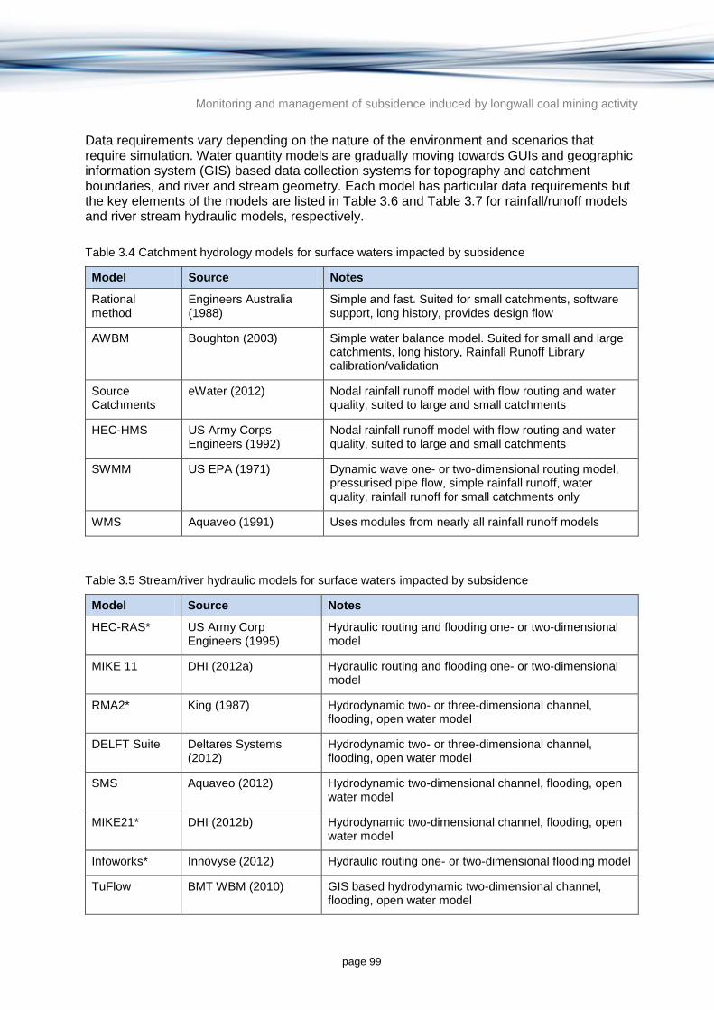
Monitoring and management of subsidence induced by longwall coal mining activity
page 99
Data requirements vary depending on the nature of the environment and scenarios that require simulation. Water quantity models are gradually moving towards GUIs and geographic information system (GIS) based data collection systems for topography and catchment boundaries, and river and stream geometry. Each model has particular data requirements but the key elements of the models are listed in Table 3.6 and Table 3.7 for rainfall/runoff models and river stream hydraulic models, respectively.
Table 3.4 Catchment hydrology models for surface waters impacted by subsidence
Model Source Notes
Rational method
Engineers Australia (1988)
Simple and fast. Suited for small catchments, software support, long history, provides design flow
AWBM Boughton (2003) Simple water balance model. Suited for small and large catchments, long history, Rainfall Runoff Library calibration/validation
Source Catchments
eWater (2012) Nodal rainfall runoff model with flow routing and water quality, suited to large and small catchments
HEC-HMS US Army Corps Engineers (1992)
Nodal rainfall runoff model with flow routing and water quality, suited to large and small catchments
SWMM US EPA (1971) Dynamic wave one- or two-dimensional routing model, pressurised pipe flow, simple rainfall runoff, water quality, rainfall runoff for small catchments only
WMS Aquaveo (1991) Uses modules from nearly all rainfall runoff models
Table 3.5 Stream/river hydraulic models for surface waters impacted by subsidence
Model Source Notes
HEC-RAS* US Army Corp Engineers (1995)
Hydraulic routing and flooding one- or two-dimensional model
MIKE 11 DHI (2012a) Hydraulic routing and flooding one- or two-dimensional model
RMA2* King (1987) Hydrodynamic two- or three-dimensional channel, flooding, open water model
DELFT Suite Deltares Systems (2012)
Hydrodynamic two- or three-dimensional channel, flooding, open water model
SMS Aquaveo (2012) Hydrodynamic two-dimensional channel, flooding, open water model
MIKE21* DHI (2012b) Hydrodynamic two-dimensional channel, flooding, open water model
Infoworks* Innovyse (2012) Hydraulic routing one- or two-dimensional flooding model
TuFlow BMT WBM (2010) GIS based hydrodynamic two-dimensional channel, flooding, open water model

Monitoring and management of subsidence induced by longwall coal mining activity
page 100
* Denotes hydraulic model capable of simulating sediment transport.
Table 3.6 Rainfall/runoff catchment hydrology model data requirements
Data requirements Sources of data
River, stream channel and catchment geometry (slope, channel dimensions, channel roughness)
topographic maps
aerial photographs
digital elevation models (DEMs)
LiDAR
field survey
Catchment land use, vegetation cover and extent, overland flow roughness
aerial photographs
LiDAR
Climate rainfall records
evaporation records
mine-based weather stations near sites of interest
Hydrology stream flow gauging station hydrographs
time-series databases (e.g. Hydstra)
Table 3.7 Stream/river hydraulic model data requirements
Data requirements Sources of data
River, stream channel and catchment geometry (slope, channel dimensions, channel roughness, gridded data for two- or three-dimensional models)
topographic maps
aerial photographs
DEMs
LiDAR
field survey
bathymetric data (two- or three-dimensional models)
Hydrology stream flow gauging station hydrographs
time-series databases (e.g. Hydstra)
3.3.2 Modelling subsidence impacts on surface water quality
Several water quality models are available from the US EPA, most of which are based on an empirical medium level water quality model (QUAL2K) that allows nutrient cycling interactions in the water column and sediments, light penetration and algal biomass to be modelled. PHREEQC allows for geochemical mixing and chemical speciation of mixing waters of differing chemical constituents. Water quality models and their capability are listed in Table 3.8.

Monitoring and management of subsidence induced by longwall coal mining activity
page 101
Table 3.8 Water quality models for surface waters impacted by subsidence
Model Source Notes
SWMM US EPA (1971) Simple user selected constituent model
QUAL2K US EPA (1987) Reach level medium level biogeochemical water quality model
WASP US EPA (1983) Reach level medium to high level biogeochemical water quality model
ECOLAB DHI (2012c) Two- and three-dimensional medium level biogeochemical water quality model
RMA 10 King (1988) Two- and three-dimensional medium level biogeochemical water quality model
PHREEQC USGS (2012) Geochemical mixing and chemical speciation model, code based model
Water quality models can vary in complexity from simple fully mixed batch reactor modelling to two- or three-dimensional finite element hydrodynamic modelling with complex biogeochemical interactions. Water quality modelling requires all the stream hydraulic data (Table 3.7) and additional information such as:
water quality physical chemical stressors and nutrients, concentrations of metals and relevant constituents, density, algal productivity
geochemical data, benthic sediment data
additional climate data such as wind speed and direction, solar radiation, cloudiness, temperature
hydrodynamic mixing data such as advection dispersion parameters, viscosity and density.
3.3.3 Modelling subsidence impacts on interaction between surface water and groundwater
Few models enable the modelling of surface and groundwater interactions, and even fewer have advanced graphic user interfaces that improve ease of use. Modelling software options available to simulate groundwater and surface water interaction are listed in Table 3.9.

Monitoring and management of subsidence induced by longwall coal mining activity
page 102
Table 3.9 Surface and groundwater interaction models for surface waters impacted by subsidence
Model Source Advantages/disadvantages Ease of Use
GSFLOW USGS (2008) Code-based groundwater and surface water flow model
Medium to hard
GSWIT (Source)
eWater (2011a)
Modules in Source Catchments and River Manger for simulation of surface water and groundwater interactions
Medium
MIKE SHE DHI( 2012d) GUI-based groundwater and surface water flow model
Medium
WARMF US EPA (2005)
Mapping-based catchment and shallow groundwater model
Medium
Surface water and groundwater interaction models such as MIKE SHE are amongst the most complex numerical modelling environments as they must be capable of simulating catchment hydrology rainfall and runoff, stream flow hydraulics, and groundwater flow through saturated and unsaturated subsurface strata. Such models require all of the data for catchment hydrology modelling (Table 3.6) hydraulic modelling (Table 3.7) and the additional information required for numerical groundwater modelling (see Section 3.2.5).
3.3.4 Modelling subsidence impacts on landscape erosion and stream geomorphology
Landscape erosion and stream geomorphological models tend to be highly empirical and there are two main approaches: complex and simplified. SIBERIA software is an example of a complex landscape erosion and stream geomorphology model and CAESAR is an example of the simplified model. The complex nature of geomorphology, sediment transport and landscape erosion models necessitate the use of numerous assumptions for parameter values in complex models. By adopting a simplified approach, less reliance is placed on empirical models and fewer assumptions need to be made. The main disadvantage with simplified models is the loss of complexity of the model itself, so the outputs and complexity of the situation to be modelled need to be considered before making a model selection.
Few models enable the predictive modelling of landscape erosion processes and river fluvial processes in a single modelling environment. The river and stream hydraulic models discussed above that have sediment transport processes include HEC-RAS, MIKE 11, RMA2, SMS, MIKE21 and Infoworks. Few of the hydraulic models can simulate erosion and re-deposition of sediment, and fewer can be used to describe stream channel meander. The main river and landscape geomorphological models are listed in Table 3.10.
Table 3.10 Stream and landscape geomorphology models for surface waters impacted by subsidence
Model Source Advantages/Disadvantages
SIBERIA Willgoose (2005) Complex code-based landscape erosion model
CAESAR Coulthard (2001) Simplified code-based landscape and fluvial erosion model
Landscape erosion, sediment transport and stream geomorphology models require similar datasets to hydrology and hydraulics models (Table 3.6 and Table 3.7) with additional

Monitoring and management of subsidence induced by longwall coal mining activity
page 103
information required such as landform geometry (in the form of a gridded digital terrain model) and optional information on soil and vegetation hydraulic properties.
3.3.5 Modelling method
3.3.5.1 Planning
The modelling project governance arrangements that are appropriate will vary depending on the size and significance of the project and will be reflected in the complexity and confidence requirements of the modelling task. Any modelling project should have both project managers and project directors. For small projects, the project manager may also be the person doing the modelling work. Project directors should be appointed to have an overseeing and review function and should therefore have appropriate technical review capacity or ability to delegate to specialist reviewers as required (which is likely given the complexity of hydrology, hydraulics, water quality and geomorphology modelling; eWater 2011a).
For major projects or projects with high levels of sensitivity, a steering committee with stakeholder representation should be established. The role of the steering committee is to provide overall direction and to facilitate stakeholder acceptance of the project, and should include key community groups and representatives affected by the proposed mining activity, along with project directors, managers and technical reviewers (eWater 2011a).
3.3.5.2 Modelling procedure
The modelling procedure for all surface water modelling (hydrology, hydraulics, water quality and geomorphology) should follow the flow chart for a quality assured model in Figure 3.7. The modelling process includes project governance, peer review, budgets, stakeholder consultation and problem definition, option modelling, and reporting phases.

Monitoring and management of subsidence induced by longwall coal mining activity
page 104
© Copyright, eWater (2011a)
Figure 3.7 Quality assured surface water modelling process
3.3.5.3 Model design and construction
Surface water modelling can be undertaken in one-, two- or three-dimensional (or partial combinations). Model build time is increased for each additional dimension, and as some issues such as geochemistry, may only be modelled in one dimension, which may require the use of linked models.
The decision to use single or multidimensional models should be made based on the complexity of the system being modelled. There is no hard and fast guidance on this issue but if the default modelling dimension is one-dimensional, two-dimensional models should only be necessary if there is a substantial area of flow direction away from the central stream line into flood plains, or complex sensitive receptors in the catchment. Three dimensions should only be required for density-dependent water quality issues, such as the simulation of salinity or temperature stratification in estuarine systems or reservoirs, or structural engineering assessment of flow/velocity effects on bridge piers or scour protection zones.
Modelling extents should be chosen carefully to minimise the data collection requirements and to improve the modelling run time and speed. In general the bigger the model extent, the larger the number of data points and hence increased numerical calculation requirement and run time. The use of existing data to provide inputs from sub-catchments can supplement modelled data from the broader catchment.
Monitoring and management of subsidence induced by longwall coal mining activity
page 105
Model extent should also take into account the requirements for cumulative impacts, and head water and tail water in hydraulics models to ensure model stability within the target surface water reach.
3.3.5.4 Model parsimony
The principal of model parsimony can be summarised as keeping the model as simple as possible to achieve the outcome required. Simple models have paybacks in immediate ways through shorter run times, but they also require fewer modelling assumptions and therefore potentially reduce modelling sources of error. In applications where linked models are being considered for the solution of a modelling problem, model parsimony will provide the additional benefits of enabling dynamically linked models rather than statically linked models, enabling some additional level of prediction in transient modelling.
3.3.5.5 Transient and steady state models
Steady state models are run to achieve a single system state such as a target downstream flow rate, a target water quality concentration, or water level. Transient models are run over time periods and involve the use of time-series data usually based on a fixed time step of minutes, hours or days. The model can be thought of as a polynomial equation with solutions and in the steady state case only one solution is sought. Transient models will give a solution for each time interval, with results handed to the next time interval.
3.3.5.6 Calibration through automated optimisation
Calibration of models requires time, and is therefore dependent on factors such as project budget, requirements for accuracy and uncertainty analysis and model complexity and run time. Short run time models are the easiest to calibrate, some multi-parameter long run time models cannot be calibrated, but may be adjusted and validated for field data.
Calibration of models has become automated through the use of complex mathematics for resolving the objective function of a model. Parameterisation can be specified to within user defined limits and the objective function will be determined to fit calibration data. External software such as PEST (Doherty 2005) and UCODE (USGS 1999), and some proprietary and open source modelling software have inbuilt optimisation functions such as Source (eWater 2009) and HEC HMS (US Army Corps Engineers 1992). The use of optimisation code to calibrate models is a double edged sword – any model, regardless of complexity, can be calibrated and optimised for the objective function for both steady state and transient models, but this means that poor quality and highly inaccurate data that is undetected will form the basis for the calibrated model.
The use of optimisation code therefore requires modellers to further ensure that their quality control and assurance processes, and both the metadata and the accuracy of modelling data itself, are fully described before being including in a model domain.
Few surface water quality or hydraulic models offer internal optimisation code. Some modelling systems such as the Rainfall Runoff Library, offer an external automated parameter optimisation for specific models as part of the eWater CRC toolkit (eWater 2008). Optimised parameters can then be transferred to rainfall runoff models on any platform with good success.
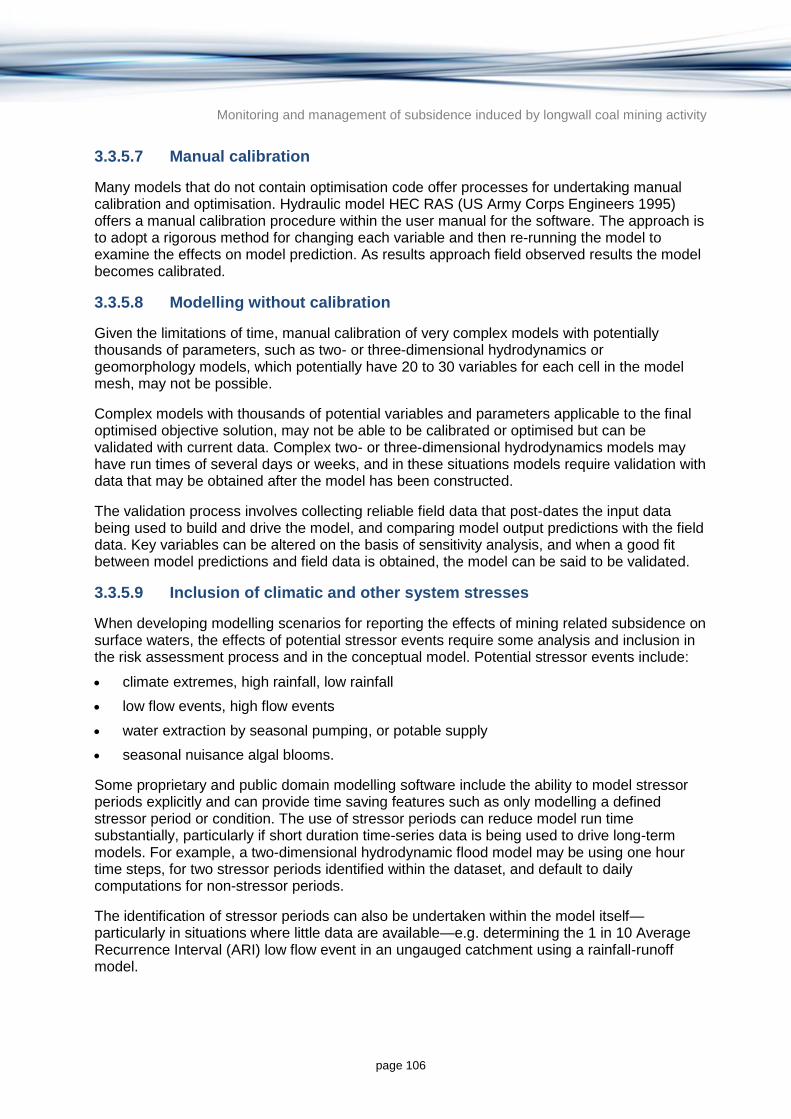
Monitoring and management of subsidence induced by longwall coal mining activity
page 106
3.3.5.7 Manual calibration
Many models that do not contain optimisation code offer processes for undertaking manual calibration and optimisation. Hydraulic model HEC RAS (US Army Corps Engineers 1995) offers a manual calibration procedure within the user manual for the software. The approach is to adopt a rigorous method for changing each variable and then re-running the model to examine the effects on model prediction. As results approach field observed results the model becomes calibrated.
3.3.5.8 Modelling without calibration
Given the limitations of time, manual calibration of very complex models with potentially thousands of parameters, such as two- or three-dimensional hydrodynamics or geomorphology models, which potentially have 20 to 30 variables for each cell in the model mesh, may not be possible.
Complex models with thousands of potential variables and parameters applicable to the final optimised objective solution, may not be able to be calibrated or optimised but can be validated with current data. Complex two- or three-dimensional hydrodynamics models may have run times of several days or weeks, and in these situations models require validation with data that may be obtained after the model has been constructed.
The validation process involves collecting reliable field data that post-dates the input data being used to build and drive the model, and comparing model output predictions with the field data. Key variables can be altered on the basis of sensitivity analysis, and when a good fit between model predictions and field data is obtained, the model can be said to be validated.
3.3.5.9 Inclusion of climatic and other system stresses
When developing modelling scenarios for reporting the effects of mining related subsidence on surface waters, the effects of potential stressor events require some analysis and inclusion in the risk assessment process and in the conceptual model. Potential stressor events include:
climate extremes, high rainfall, low rainfall
low flow events, high flow events
water extraction by seasonal pumping, or potable supply
seasonal nuisance algal blooms.
Some proprietary and public domain modelling software include the ability to model stressor periods explicitly and can provide time saving features such as only modelling a defined stressor period or condition. The use of stressor periods can reduce model run time substantially, particularly if short duration time-series data is being used to drive long-term models. For example, a two-dimensional hydrodynamic flood model may be using one hour time steps, for two stressor periods identified within the dataset, and default to daily computations for non-stressor periods.
The identification of stressor periods can also be undertaken within the model itself—particularly in situations where little data are available—e.g. determining the 1 in 10 Average Recurrence Interval (ARI) low flow event in an ungauged catchment using a rainfall-runoff model.

Monitoring and management of subsidence induced by longwall coal mining activity
page 107
3.3.5.10 Modelling changes due to subsidence
Modelling of surface water scenarios already regularly involves the assessment of topography and catchment changes within the disciplines of hydrology (land use change, vegetation change) hydraulics (waterway design and diversion drainage modification) geomorphology (vegetation and topography change). Modelling of water quality and geochemistry will also be able to deal with most dissolved single phase solids and liquids for physico-chemical parameters, within the normal range of monitoring scenarios.
The exceptions to this are dual phase modelling issues simulating water quality effects of gas phase interactions on aquatic ecosystems, which is not as well developed and so therefore will need a cautious approach. There are no identified off the shelf models that are capable of modelling gas phase effects on water columns.
Ecosystem modelling can be complex and generally available quantitative data on parameters that effect species and particularly Australian native species, is poor to very poor. Therefore, gas phase and ecosystem modelling, if required, may require the collection of additional site specific data to enable suitable models to be constructed. Common issues related to the modelling of longwall mining related subsidence will be described in the next sections.
3.3.5.11 Ungauged catchments and flood prediction
Mining activities in many cases will be occurring in remote areas and/or ephemeral systems that will suffer from a lack of data. This can be overcome by selecting a series of appropriate linked models. One of the most common place examples of this would be the lack of streamflow gauging data (ungauged catchments) in the area impacted by subsidence. The use of a hydrologic model linked to a hydraulic model would be a standard approach to assessing flooding and water level issues on flood plains and impacted ecosystems. It is important to use an integrated rainfall runoff and stream routing model such as RORB (particularly for design and sub-daily flows) that will properly estimate flood flows in the catchment network. The use of a rainfall runoff models alone will not provide sufficient estimates of flood flow as in most cases a 1:100 rainfall event does not equal and 1:100 or 1:200 flood event due to the effects of localised storm development and large catchment size.
3.3.6 Outputs
Model outputs can vary from simple tables to advanced two- and three-dimensional graphics, model cross-sections and elevations/projections through to video animations of transient modelling scenarios. Model visualisation is an important part of model building and errors analysis, and is also important to effectively communicate the results of model outputs to specialist and non-specialist audiences. The model selection process needs to consider the needs for model outputs and potential audience visualisation requirements for presentations, documents, information brochures and reports.
Spatial databases are also useful platforms for displaying modelling outputs. Many surface water modelling systems have inbuilt export tools to enable GIS-ready data for display.
3.3.7 Uncertainty and accuracy
There are typically three main sources of uncertainty in any modelling problem:
the structure of the model and how well it represents the ‘real world’ for the purpose of the modelling exercise

Monitoring and management of subsidence induced by longwall coal mining activity
page 108
estimates of the model parameters, assuming the model structure is known
random variation in the observed variables, as well as measurement and recording errors (Chatfield 1996).
Estimating uncertainty in parameter values can be undertaken using inferential statistical processes and linear and non-linear individual confidence intervals (Hill & Tiedeman 2007). Uncertainty can be checked against reasonable parameter values from previous studies and relevant literature. Statistical indications of data uncertainty can be determined using the sample size and population of the dataset.
The smallest possible number of parameters should be used so as to give an adequate representation of the data and the principle of modelling parsimony should be applied when model specification and selection is taking place. The more complicated the model, the more possibilities there will be for departures from model assumptions (Chatfield 1996).
Predictive uncertainty can be analysed after model parameter sensitivity analysis has been undertaken. There are a variety of statistical techniques which can be applied to modelling predictions and parameters, including parameter prediction and observed parameter analysis (Hill & Tiedeman 2007). Confidence interval approaches can also be used to convey the relative confidence of model outputs, and parameter influence on model outputs.
Model accuracy (as opposed to uncertainty) is to some extent a function of model calibration processes, and can be assessed by evaluating the fit between modelled and observed data, and by evaluation of optimised parameter values. Standard error and other statistics can be used to assess model fit, and residuals can be used for detailed analysis (Hill & Tiedeman 2007).
3.3.8 Case study applications
3.3.8.1 Ensham Central Project, Queensland
Ensham Mine is a large open cut coal mine located approximately 40 km east of Emerald, Central Queensland. The Ensham Central Project EIS was released in 2006 (Hansen 2006). The project included areas of longwall underground mining and predicted subsidence (Figure 3.8).
Subsidence effects from underground mining areas were predicted to be approximately 2.7 m and form a series of shallow trough like depressions. The land affected by subsidence is in the Nogoa River flood plain and the mine layout was designed so that there would be no subsidence within a buffer zone of 100 m from the top of the high bank of the main channel of the Nogoa River. Subsidence predictions were made using the Surface Deformation Prediction System (see Section 3.1.1.3).

Monitoring and management of subsidence induced by longwall coal mining activity
page 109
© Copyright, Hansen (2006)
Figure 3.8 Ensham Central Project location and layout
Hansen (2006) identified that the predicted subsidence would potentially affect surface drainage, groundwater and land use. Potential effects of subsidence on surface drainage were identified as:
initiation of localised erosion
localised alteration of surface drainage paths
formation of localised surface depressions
initiation of creek line erosion due to local steepening of bed grades.
Hansen (2006) suggested that monitoring for these effects would be conducted periodically and remedial drainage, erosion and sediment control works would be undertaken where necessary to mitigate the effects. Proposed remedial works included:
rehabilitation of surface cracks by ripping/ploughing and reseeding where necessary
minor remedial drainage earthworks to redirect drainage paths
minor cut and fill earthworks to re-establish free drainage in depressions or ponded areas
minor creek line drainage works or stabilisation works to remediate areas prone to erosion.
The plan included constructing excavated trapezoidal drainage channels to progressively re-establish free drainage in the subsidence area. The channels were designed drain subsidence troughs along pre-existing drainage lines. Excavated material from the channels was used for filling in any nearby ponding areas. Subsidence effects on Winton Creek were to be remediated with drainage earthworks and rehabilitation designed to ensure that the stability of the creek was not adversely affected by changes in the grade of the creek bed. The

Monitoring and management of subsidence induced by longwall coal mining activity
page 110
proposed works included re-grading of sections of the creek bed and creek stabilisation works including revegetation and installation of scour protection in sections of steep bed grades.
Surface water hydraulic flood modelling with Delft FLS modelling indicated that surface subsidence effects would not lead to adverse upstream drainage effects. Results indicated that peak floodplain flow velocities in the subsided area would not increase significantly as a result of the subsidence effects and would remain less than 1 m/second even in extreme flood events. The low flow velocities were not considered likely to initiate significant erosion on subsided areas vegetated with pasture or crop stubble cover. Geomorphological effects were also evaluated as being acceptable with the Delft FLS modelling (Hansen 2006).
3.3.8.2 Bulli Seam, NSW
Bulli Seam Operations were the subject of an EIS in 2009 (Gilbert & Associates 2009) and are located approximately 30 km north of Wollongong, NSW (Figure 3.9). A stream risk assessment was conducted for longwall mining operations in the project areas, and 47 rivers and significant streams were identified. The main rivers and significant stream catchment systems in the project extent of longwall mining area were the Nepean River, the Cataract River, the Georges River, the Woronora River and O’Hare’s Creek.
Risk management zones were applied to relevant streams and the predicted subsidence effects were calculated using empirical relationships from similar geologies reported in MSEC (2009). The likelihood and level of potential impacts of subsidence on flow and water quality in streams was found to depend on a number of specific site attributes including the geomorphic nature and hydrological characteristics of the stream. The character of streams in the project area varied significantly in terms of scale, geology, geomorphic character and existing land use.
Connective cracking from the ground surface to the mined seam was not expected; although stream beds with exposed rock base were expected to experience subsidence induced fracturing to a depth of 10 to 20 m. This was considered to present negligible potential for the loss of surface water to the mine due to the lack of continuity of fractures from the surface to the mine. It was considered that a portion of surface water flows may be diverted through the rock fractures beneath the stream bed, with emergence further downstream. The project would not therefore affect the quantity of water reaching the Cataract Dam, Woronora Dam or Broughton's Pass Weir. Mine subsidence effects were predicted to locally change water quality; however the project was not expected to have an effect on the water quality of Woronora Reservoir, Cataract Reservoir or Broughton's Pass Weir.
The main impacts on surface waters were identified as:
fracturing of controlling rock bars, resulting in the diversion of some stream flow
potential for fracturing of stream bed, resulting in the loss of some streamflow
localised impacts on water quality
strata gas release.

Monitoring and management of subsidence induced by longwall coal mining activity
page 111
© Copyright, adapted from Gilbert and Associates (2009)
Figure 3.9 Location of the Bulli Seam Operations and nearby surface waters
A simple water balance model using AWBM (Boughton 2003) was constructed for the most important rock bar pools and the mine site. Figure 3.10 shows the conceptual model for the rock bar pool water balance model.
© Copyright, Gilbert and Associates (2009)
Figure 3.10 Water balance model schematic for a rock bar pool

Monitoring and management of subsidence induced by longwall coal mining activity
page 112
Several scenarios for pool size geometry were simulated to predict the impact on flow frequency as a result of subsidence related fracturing near the surface. Figure 3.11 shows the predicted flow exceedance probabilities after subsidence compared to the pre-mined condition for a 2 m deep pool with dimensions 200 by 8 m.
© Copyright, Gilbert and Associates (2009)
Figure 3.11 Modelled flow exceedance curves for a pool showing the effect of subsidence
Results of the pool modelling indicated that the frequency that pools would be full or near full might decrease by a few per cent in some cases and up to 50 per cent in rare situations. Small, shallow pools in small catchments, which become well connected to extensive subsidence induced fracture networks were considered most likely to experience periodic drying. Small, deeper pools in large catchments with strong low flow persistence were considered less likely to be affected by subsidence induced bed fracturing. Streams formed in the Hawkesbury Sandstone terrains of the project area were identified as typically containing a wide range of different pool sizes and types and a range of different effects were predicted in response to subsidence induced dilation fracturing (Gilbert & Associates 2009).

Monitoring and management of subsidence induced by longwall coal mining activity
page 113
4 Evaluation of monitoring and measurement approaches
4.1 Monitoring subsidence
This chapter provides a summary of the methods available to monitor surface and subsurface subsidence and related movements. It includes assessments of the accuracy and cost of various methods that have been used in Australia and elsewhere.
The necessity for subsidence monitoring in Australia was recognised by the Stored Waters Inquiry (Reynolds 1977), and by the early proponents of longwall mining through their appointment of specialist subsidence engineers. The aims of subsidence monitoring, as applied in the Sydney Basin since the 1970s, encompass:
measuring ground movements in three dimensions, which can be converted into parameters such as vertical and horizontal movement, tensile and compressive strains, tilt and curvature
progressively recording movements using repeated surveys along established peg lines as the subsidence profile develops
providing information to improve future mine layout designs and for better subsidence mitigation measures
meeting regulatory constraints, as specified in pre-mining Subsidence Management Plans.
The period of monitoring should be commensurate with the expected timing of subsidence determined from predictive techniques such as empirical and numerical modelling methods (Sections 3.1 and 3.1.2 discuss predictive techniques). Generally, the deeper the workings are, the longer the time taken for surface subsidence to cease (Section 2.2).
4.1.1 History of ground survey methods
Australian monitoring procedures initially followed those pioneered by the UK National Coal Board (NCB 1966, 1975), which were based on levelling lines of survey pegs laid out along panel centre lines and surveying distances between the pegs. Pegs were driven to refusal using a sledge hammer into hard rock with concrete capping placed at surface level around each peg for lateral stability. Pegs are usually spaced at about five per cent of the mining depth, typically 5 to 20 m apart. Survey lines are now typically transverse and diagonal as well as longitudinal, and are laid out to extend beyond the expected AoD, typically 100 to 300 m outside the limits of the mined area.
Early surveys provided estimates of vertical subsidence movements and the relative movement between consecutive pegs but could not usually measure horizontal surface displacements. Furthermore the end pegs on each line were assumed to be fixed and maximum ground strains were assumed to occur along these lines (the panel centre line), since these were the only directions in which measurements were taken (Mills 2011).
Laser theodolites and three-dimensional location techniques in the 1980s revolutionised subsidence monitoring. Horizontal movements were detectable to an accuracy of a few

Monitoring and management of subsidence induced by longwall coal mining activity
page 114
millimetres and peg sites could be measured faster and hence more cheaply than previous levelling and chaining methods.
More recently, precision global positioning systems (GPS) allow control points to be located well outside the area of influence, since it had been found that small but measurable horizontal movements were occurring up to 1 km or more beyond the previously accepted subsidence limit (Holla & Barclay 2000). GPS-based methods implemented in the Southern Coalfield have enabled such far-field movements to be captured (Anderson et al. 2007).
4.1.2 Ground survey techniques
Ground survey techniques usually involve the development of a network of pegs or permanent survey marks (PSMs) with a higher density over the area of longwall coal mining. In some circumstances it can be an advantage to survey PSMs along an existing geophysical (seismic) section line, which allows evaluation of deformation against interpreted geological structure data. Traditionally PSMs are placed in positions where they are unlikely to be disturbed or damaged by processes other than those being monitored (e.g. damaged by a vehicle driving over it). The term ‘bench mark’ (BM) is used to describe a PSM when its vertical position is known or monitored, but not its horizontal position. Once a network of PSMs has been established they can be re-observed at a later date to determine the amount of movement. Changes in position of PSMs provide a measure of movement at discrete locations across a study area. Figure 4.1 shows example results of subsidence monitoring from Westcliff Colliery, NSW, measured by surveying a line of pegs (labelled in the figure as B084 to B234) during extraction of a longwall panel (extraction of panel LW34, following previous extraction of LW29, LW31B, LW32 and LW33). On a mine site there would be hundreds of lines of pegs monitored on a regular basis.
In Australia the Inter-governmental Committee on Surveying and Mapping (ICSM) defines ‘Standards and Practices for Control Surveys’, often referred to as ‘SP1’ (ICSM 2007). It sets out clear accuracy standards for various control surveys. SP1 provides recommended survey and reduction practices for vertical and horizontal control surveys carried out using analogue or digital levels, electronic total stations (electronic theodolites with built in distance measurement) and survey grade Global Navigation Satellite System (GNSS) receivers. In Australia, SP1 is the primary reference document used by surveyors to determine the most appropriate survey techniques and data reduction practices required to meet specified accuracy expectations for control surveys.

Monitoring and management of subsidence induced by longwall coal mining activity
page 115
© Copyright, MSEC (2010)
Figure 4.1 Results of subsidence monitoring from a single line of pegs at Westcliff Colliery (labelled as B084 to B234) during extraction of a longwall panel
A number of land surface surveying techniques are available to accurately measure position and change in position over time including:
precise levelling
control traversing
GNSS.
4.1.2.1 Precise levelling
The height of PSMs can be most accurately determined by precise levelling, which measures the differential elevation between sites and adopts a more rigorous observing procedure than general engineering levelling.
Accuracies in the order of 1 mm over 1 km can be achieved. Precise levelling is typically carried out using a digital level which electronically reads a bar-coded scale on the staff and includes data recording and reduction capabilities.
Although the method provides very precise height measurement at discrete points, it can be labour intensive, particularly over large areas or in steep terrain.

Monitoring and management of subsidence induced by longwall coal mining activity
page 116
4.1.2.2 Control traversing
The vertical and horizontal coordinates of PSMs can be accurately determined by using a survey technique known as traversing, which is used to establish survey control networks. Traversing can achieve accuracies in the order of 5 to 10 mm over 1 km and is typically carried out using Electronic Total Station instruments that enable multiple rounds of angles and distances to be observed and recorded without the need to manually point the instrument or record observations.
Traverse networks involve placing PSMs along a line or path of travel and measuring angles and distances between them to determine the location of the next PSM. Positions are carried forward from the current traverse station (PSM) by measuring angles between the previous traverse station and next traverse station and by measuring the distances and vertical angles between adjacent traverse stations (Figure 4.2). The main advantage of this method is that it provides very high quality horizontal measurements as well as vertical measurement at discrete points.
© Copyright, GlobalSecurity (2013)
Figure 4.2 Measurements made in a control traverse
4.1.2.3 Global Navigation Satellite Systems (GNSS)
GNSS is a generic term that refers to all global navigation satellite systems. The Global Positioning System (GPS) is the most widely known of these systems, and refers specifically to the US navigation satellite system.
GNSS ‘survey’ receivers differ significantly from commercially available ‘navigation’ receivers. Navigation receivers (the type used for bushwalking, boating or in-car navigation) rely on signals broadcast from GNSS satellites to calculate position to an absolute accuracy in the order of 5 to 10 m. Encrypted satellite signals can be interpreted by military navigation receivers to determine more accurate position fixes, but even these do not approach the accuracy required for control surveys.
GNSS survey receivers measure the difference in phase between one or more of the carrier waves transmitted by navigation satellites to derive very accurate three-dimensional baselines or vectors between pairs of GNSS survey receivers (Figure 4.3). Baselines between survey receivers can be measured to accuracies in the order of one part per million (or 1 mm over 1 km).
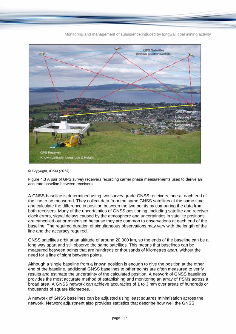
Monitoring and management of subsidence induced by longwall coal mining activity
page 117
© Copyright, ICSM (2013)
Figure 4.3 A pair of GPS survey receivers recording carrier phase measurements used to derive an accurate baseline between receivers
A GNSS baseline is determined using two survey grade GNSS receivers, one at each end of the line to be measured. They collect data from the same GNSS satellites at the same time and calculate the difference in position between the two points by comparing the data from both receivers. Many of the uncertainties of GNSS positioning, including satellite and receiver clock errors, signal delays caused by the atmosphere and uncertainties in satellite positions are cancelled out or minimised because they are common to observations at each end of the baseline. The required duration of simultaneous observations may vary with the length of the line and the accuracy required.
GNSS satellites orbit at an altitude of around 20 000 km, so the ends of the baseline can be a long way apart and still observe the same satellites. This means that baselines can be measured between points that are hundreds or thousands of kilometres apart, without the need for a line of sight between points.
Although a single baseline from a known position is enough to give the position at the other end of the baseline, additional GNSS baselines to other points are often measured to verify results and estimate the uncertainty of the calculated position. A network of GNSS baselines provides the most accurate method of establishing and monitoring an array of PSMs across a broad area. A GNSS network can achieve accuracies of 1 to 3 mm over areas of hundreds or thousands of square kilometres.
A network of GNSS baselines can be adjusted using least squares minimisation across the network. Network adjustment also provides statistics that describe how well the GNSS

Monitoring and management of subsidence induced by longwall coal mining activity
page 118
baselines fit together and how well they fit the known PSMs, as well as providing valuable information on the reliability of the newly calculated coordinates of previously unknown PSMs.
Real time kinematic surveying is similar to the GNSS baseline method, except that while one GNSS survey receiver remains stationary on a known PSM (base station), the other moves or roves between points and only needs to be stationary at each point for a few seconds (Figure 4.4). Horizontal coordinates derived from single real time kinetic measurements are typically accurate to around 20 mm.
© Copyright, ICSM (2013). A survey receiver at the base station transmits phase measurements in real time to the roving survey receiver to determine the baseline and the rover’s position.
Figure 4.4 A real time kinematic GNSS survey
4.1.3 Remote sensing methods
Ground surveys are limited to monitoring at specific locations and rely on interpolation of surface change in areas outside the monitoring points. Airborne and satellite based remote sensing techniques offer new possibilities for monitoring surface movement and deformation when used in conjunction with ground based methods.
Remote sensing methods offer the advantage of continuous datasets over broad areas. Repeat surveys can also provide time series subsidence monitoring in the mining zone and the greater surrounds.
In the Australian subsidence monitoring context, ACARP undertook extensive investigation of radar interferometry for mine subsidence monitoring using satellite based sensors (Ge et al.

Monitoring and management of subsidence induced by longwall coal mining activity
page 119
2004). Shortcomings include potential errors over changing surface cover such as vegetation, changes in ground slope and atmospheric conditions. These are summarised below for each of the remote sensing techniques.
Remote sensing techniques can be cost-effective compared with ground survey methods when a number of mines are in close proximity and can be monitored in a single satellite scene under a single analysis, compared to ground transects which are field intensive and costly over large areas (e.g. Figure 4.5).
© Copyright, Ge et al. (2004)
Figure 4.5 Three underground coal mines in close proximity: Tower (blue; left), Appin (red; centre) and West Cliff (orange; right) which can be monitored in a single satellite scene under a single analysis, compared to the single ground transects (yellow lines) which are more field intensive and costly to survey
4.1.3.1 Digital photogrammetry
Photogrammetry is the practice of determining the geometric properties of objects from photographic images. It is a passive form of remote sensing that relies on ambient visible or infrared light reflected from the surface. Optical stereo imaging using digital photogrammetry can be used to generate a terrain model at intervals before and after mining to monitor subsidence determined by elevation difference.
Stereo imagery is typically acquired by taking a series of overlapping perspective centred images or an image strip which acquires multiple view angles in a single pass. Both provide stereo coverage but with different effects on the perspective of the imagery. The process involves calculating the three-dimensional coordinates of an object visible in overlapping images (referred to as a stereo model). Common points are identified on each of the

Monitoring and management of subsidence induced by longwall coal mining activity
page 120
overlapping images, and lines of sight (or rays) can be constructed from the camera locations to each object. The intersection of these rays (triangulation) determines the three-dimensional location of objects.
The benefit of using stereo imaging, like all remote sensing methods, is the ability to monitor areas with field access constraints. Spreckels (2000) assessed digital photogrammetry over a German mine site to monitor subsidence, and vertical movements larger than 200 mm were detected using an airborne high resolution stereo camera. Aerial imagery can be purpose flown to specifications to meet user’s needs however, measurements can only be made in areas where the land surface is visible. Areas of dense vegetation or where shadow occludes vision to the sensor are not suitable. This is a serious shortcoming in Australian longwall mining areas, where forest and scrub cover is common. Furthermore vertical movements should be accurate to approximately 20 mm rather than 200 mm to be useful for subsidence monitoring.
4.1.3.2 Light detection and ranging
Similar to photogrammetry, differences in terrain models can be used to quantify subsidence using airborne laser scanning (ALS), which uses light to measure elevation (commonly referred to as light detection and ranging or LiDAR). LiDAR is a remote sensing technology that measures distance by illuminating a target with a laser and analysing the reflected light. The term airborne LiDAR involves using a LiDAR system in a moving aircraft and is often referred to as ALS. ALS has become popular for the acquisition of digital terrain or surface data over broad areas. LiDAR surveys can achieve a vertical accuracy of 100 to 150 mm, following the Australian LiDAR Acquisition Standards (ICSM 2011).
A study completed in the NSW Mandalong Valley demonstrated that LiDAR modelling and conventional field based methods differed by 150 vertical mm (Harrower et al. 2010), suggesting that LiDAR error is too high to for the technique to be used in its own right. The study found LiDAR was an appropriate technology to supplement existing conventional monitoring and has advantages in enabling temporal comparisons over a broad area. Temporal subsidence monitoring is limited when using LiDAR as the processing algorithms which classify the elevation measurements into ‘ground’ (such as bare earth) and ‘non-ground’ points (such as trees, water bodies, buildings, etc.) change over time as the technology advances. Like most imaging sensors, the most reliable measurements would be achieved over areas of bare ground where obstructions are minimal.
The advantage of using LiDAR is the density of elevation points, which provide a vertical profile every 1 to 2 m at an accuracy of approximately 100 to 150 mm. When calibrated with surface measurements, it can provide the level of accuracy usually required for subsidence monitoring.
4.1.3.3 Satellite radar imaging
Interferometric synthetic aperture radar (InSAR) is an active remote sensing system. Unlike LiDAR, which is subject to visibility requirements, InSAR can operate in any weather conditions, day or night. InSAR emits a variety of wavelengths depending on the particular system, some of which can penetrate vegetation.
Differential interferometric synthetic aperture radar (DInSAR) uses a pair of microwave sensing images to detect surface changes and has gained significant interest from the mining industry (Figure 4.6). It can monitor vertical deformation to millimetre accuracies, including in areas of dense vegetation, but does not perform as well in areas of marked changes of grade,
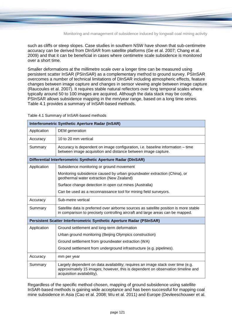
Monitoring and management of subsidence induced by longwall coal mining activity
page 121
such as cliffs or steep slopes. Case studies in southern NSW have shown that sub-centimetre accuracy can be derived from DInSAR from satellite platforms (Ge et al. 2007; Chang et al. 2009) and that it can be beneficial in cases where centimetre scale subsidence is monitored over a short time.
Smaller deformations at the millimetre scale over a longer time can be measured using persistent scatter InSAR (PSInSAR) as a complementary method to ground survey. PSInSAR overcomes a number of technical limitations of DInSAR including atmospheric effects, feature changes between image capture and changes in sensor viewing angle between image capture (Raucoules et al. 2007). It requires stable natural reflectors over long temporal scales where typically around 50 to 100 images are acquired. Although the data stack may be costly, PSInSAR allows subsidence mapping in the mm/year range, based on a long time series. Table 4.1 provides a summary of InSAR-based methods.
Table 4.1 Summary of InSAR-based methods
Interferometric Synthetic Aperture Radar (InSAR)
Application DEM generation
Accuracy 10 to 20 mm vertical
Summary Accuracy is dependent on image configuration, i.e. baseline information – time between image acquisition and distance between image capture.
Differential Interferometric Synthetic Aperture Radar (DInSAR)
Application Subsidence monitoring or ground movement
Monitoring subsidence caused by urban groundwater extraction (China), or geothermal water extraction (New Zealand)
Surface change detection in open cut mines (Australia)
Can be used as a reconnaissance tool for mining field surveyors.
Accuracy Sub-metre vertical
Summary Satellite data is preferred over airborne sources as satellite position is more stable in comparison to precisely controlling aircraft and large areas can be mapped.
Persistent Scatter Interferometric Synthetic Aperture Radar (PSInSAR)
Application Ground settlement and long-term deformation
Urban ground monitoring (Beijing Olympics construction)
Ground settlement from groundwater extraction (WA)
Ground settlement from underground infrastructure (e.g. pipelines).
Accuracy mm per year
Summary Largely dependent on data availability; requires an image stack over time (e.g. approximately 15 images; however, this is dependent on observation timeline and acquisition availability).
Regardless of the specific method chosen, mapping of ground subsidence using satellite InSAR-based methods is gaining wide acceptance and has been successful for mapping coal mine subsidence in Asia (Cao et al. 2008; Wu et al. 2011) and Europe (Devleeschouwer et al.

Monitoring and management of subsidence induced by longwall coal mining activity
page 122
2007; Raucoules et al. 2007). The number of radar satellites with interferometric capabilities has grown exponentially in the last few years as data has become increasingly accessible (Table 4.2 shows a summary of past, operational and future satellite radar missions).
© Copyright, Ge et al. (2004). The underground mine plan is shown in red, surveying routes are shown in yellow and the colour legend shows land subsidence in centimetres.
Figure 4.6 DInSAR mine subsidence map in southwest NSW
Table 4.2 Summary table of past, operational and future satellite radar missions (not exhaustive)
Sensor, agency Imaging band
Temporal cycle
Approx. ground resolution
Approximate coverage
Lifespan
ERS-1, European Space Agency
C 35 days (24 h tandem)
26 x 30 m 100 km Jul 1991 – Mar 2000
ERS-2, European Space Agency
C 35 days (24 h tandem)
26 x 30 m 100 km Apr 1995 – Sep 2011
JERS-1, Japan Aerospace Exploration Agency
L 44 days 18 x 18 m 75 km 1992 to 1998
Radarsat-1, Canadian Space Agency
C 24 days 8–100 m 45–500 km from Nov 1995
Radarsat-2, Canadian Space
C 24 days 8–100 m 40–500 km from Dec

Monitoring and management of subsidence induced by longwall coal mining activity
page 123
Sensor, agency Imaging band
Temporal cycle
Approx. ground resolution
Approximate coverage
Lifespan
Agency 2007
ENVISAT, European Space Agency
C 35 days 30 m 100–500 km Mar 2002 – May 2012
ALOS PALSAR, Japan Aerospace Agency
L 23.5 days 7–100 m 40–350 km Jan 2006 – Apr 2011
COSMO-SkyMed1-4, Italian Space Agency
X 16 days 1 x 1 m 3 x 3 m 5 x 5 m 30 x 30 m 100 x 100 m
10 m 30 m 40 m 100 m 200 km
Jun 2007 –Dec 2007 Oct 2008 – Nov 2010
TerraSAR-X, German Aerospace Agency
X 11 days 1 m 3 m 16 m
15 x 10 km 30 m x 1500 km 100 x 1500 km
From Jun 2007
Huan Jing-1, China Centre for Resources Satellite Data and Application
S 31 days 5 m 20 m
40 km 10 km
From Nov 2012
Sentinel-1, European Space Agency
C 12 days 5 x 20 m 20 x 40 m
250–400 m From 2014
ALOS PALSAR-2, Japan Aerospace Agency
L 14–66 days 3–100 m 25–490 km From 2014
Future proposed missions
COSMO-SkyMed 2nd
Gen, Italian Space Agency
X 16 days 1 m 3 m 20 – 40 m 15 m
10 km 40 km 100–200 km 30 km
Expected launch 2015, 2016
TerraSAR-X2, German Aerospace Agency
X 1–4 m 5–50 m
10–40 km 50–500 km
Expected launch 2015
RADARSATC-3, Canadian Space Agency
C 12 days 3–100 m 20–500 km Expected launch 2015
TanDEM-L, German Aerospace Agency
L 8 days 20–100 m 350 km Expected launch 2017
Monitoring and management of subsidence induced by longwall coal mining activity
page 124
4.1.4 Evaluation of surface subsidence monitoring methods
In recent years, GPS technology has enhanced ground survey techniques allowing quicker and cheaper surveys relative to traditional pegged lines measured with theodolites. A suite of new techniques have become available in recent years (summarised in Table 4.3). Digital photogrammetry and ALS do not currently have the vertical elevation accuracy for widespread use in monitoring mining induced subsidence and suffer from vegetation obstructing land surface measurements. The most promising technology is satellite radar imaging, which has the capacity to provide vertical accuracies to millimetre level.
Ge et al. (2007) reports an accuracy of 20 mm for a NSW case study using satellite radar and a DInSAR analysis technique. However, as technology advances and there is greater choice for selecting image data in optimal geometries within ideal temporal baselines, there is an expectation that this accuracy will improve. In addition, radar has the ability to monitor regional lateral far-field effects because radar images can cover a large area in a single image analysis (Chang et al. 2009).
Table 4.3 Summary of remote sensing methods for subsidence monitoring
Photogrammetry
Light Detection and Ranging (LiDAR)
Interferometric Synthetic Aperture Radar (InSAR)
Platform Aerial and space borne Aerial Aerial and space borne
Sensor Passive optical sensor.
Images acquired by area or line sensors.
Active near infrared sensor, typical wavelength 900 nm.
Active microwave sensor, typical wavelengths: X-band, 3 cm; C-band, 6 cm; L-band, 24 cm and P-band 65 cm.
Geometry Perspective geometry, requiring at least two images of overlapping area from different view directions.
Near-vertical geometry with polar coordinate determination.
Narrow scan widths of 1 km or less, typical incidence angle +/- 20 degrees.
Side-looking geometry with two radar antennas.
Typical incidence angles 30 to 60 degrees, phase difference of returned signals measured.
Acquisition Weather and illumination dependent.
Large range of flying height and speed
Sub-m pixel size
Satellite imagery can capture up to 300 square km scenes.
Weather dependent, flying height 300 to 2000 m, flying speed 200 km per hour, ground strip width depends on flying height.
Weather and light independent, aerial flying height 5 to 40 km, flying speed greater than LiDAR, ground swath 5 to 10 km depending on flying height.
Elevation measures
Image matching from stereo pairs is used to find differences in parallax to calculate surface elevation.
Distance to a feature is a function of time it takes for emitted signal to return.
Phase difference from two SAR images is used to process height information.
Vertical accuracy for height models
Vertical accuracy is a function of photo scale; rough indication for aerial photography is that vertical
RMSE* values: 0.1 to 0.3 m.
RMSE* values: 0.5 – 5 m (aerial); 6 m (Shuttle Radar Topography Mission); 10 – 20 m (space borne InSAR); 0.2 –
Monitoring and management of subsidence induced by longwall coal mining activity
page 125
Photogrammetry
Light Detection and Ranging (LiDAR)
Interferometric Synthetic Aperture Radar (InSAR)
accuracy is around 1:8000 of flying height.
Satellite imagery can achieve height accuracy to 2 to 3 pixels.
1 m (DInSAR); mm/year (PSInSAR)
* RMSE = RMS error – see glossary for explanation
Traditional GPS-based ground surveys are likely to remain the dominant method for monitoring longwall coal mine subsidence for single mines due to cost considerations in the near-term. In areas where mines are clustered and cost sharing options are available, satellite radar technology is already cost-effective and has the necessary vertical accuracy. As new satellites are launched and new processing techniques become available over the next 5 years (Table 4.2), satellite radar technology will become more cost-effective and commonly used for monitoring mine subsidence.
4.1.5 Subsurface subsidence monitoring
Ground survey methods and remote sensing techniques only provide data on surface movements. However, subsurface movements are also important to monitor caving mechanisms, to detect horizontal cracking and to document which overburden layers resist subsidence (i.e. where they are bridging).
Subsurface monitoring is not as common as conventional survey methods. In NSW nearly all longwall panels are surveyed on the surface, but few have subsurface monitoring because of cost considerations.
An extensometer is typically used to monitor subsurface subsidence, and measures the amount of downward movement at many levels in a borehole. Other instruments sometimes installed in subsidence monitoring boreholes include tiltmeters, which record changes from vertical in the borehole, and seismic sensors (geophones), which can be used to determine where the caving is occurring as a longwall face mines through the seam beneath ground. Such instrumentation is not routinely installed.
Results from instrumentation and testing in boreholes in completed coal mine workings or in planned longwall panels have thrown much light on subsidence mechanisms, though these remain primarily research tools rather than routine monitoring techniques. The purpose of these devices and tests is to:
record overburden movements and fracturing at depth, especially vertical strains and rock mass dilations
measure the height and degree of caving and fracturing above the mined seam
study the process of subsidence development, since the monitoring borehole is usually sited on a panel centre line ahead of the face, and therefore experiences the full subsidence wave
locate where overburden layers are pulling apart (delamination horizons), which might become groundwater leakage zones or entry points for methane

Monitoring and management of subsidence induced by longwall coal mining activity
page 126
locate lateral movements along bedding planes in the overburden (although the capacity to measure lateral strains in boreholes is limited). Displacements of this type are responsible for far-field movements.
The capabilities of borehole devices are summarised below based largely on information in Mills (2011).
Multi-anchor extensometers are used in shorter boreholes to measure coal rib and roof deformation. A series of anchors, typically about 20, are embedded at varying heights in a large diameter open borehole sited over the centre line of the panel to be monitored. Relative movement between the anchors is measured by displacement of the wires at the surface, which are kept taut by counter weights. Increase in distance between the anchors is taken to indicate that cracks have opened between them. A schematic example is shown in Figure 4.7.
Surface extensometers are used mainly to locate delamination horizons and measure vertical strains, hence rock mass dilation during subsidence. Though expensive, they are probably the most widely installed form of borehole instrumentation and have operated in NSW collieries since the 1980s.
© Copyright, Holla (2000)
Figure 4.7 Simple set up of an extensometer measuring subsurface subsidence

Monitoring and management of subsidence induced by longwall coal mining activity
page 127
4.1.5.1 Inclinometers and stress meters
Lateral movement and shearing along bedding planes may be detectable using inclinometers or tilt meters, which use grouted vertical boreholes lined with cruciform slotted PVC casing. A travelling sonde is fitted into the slots recording out-of-vertical deformations, before being withdrawn at the end of the measuring round. Readings can only be taken down to the highest horizontal shear zone in the borehole (i.e. where it closes off), which will rise progressively through the caving process.
Stressmeters are likewise most applicable in relatively shallow boreholes (e.g. down to 30 m). They record variations in lateral stress across the borehole walls, but not the full three-dimensional stress field during the loading/unloading phases of the subsidence wave.
4.2 Groundwater monitoring
Groundwater is a key resource which can be affected by longwall coal mine subsidence (Section 2.3). This section details the need to monitor groundwater in and around longwall coal mines and evaluates the main techniques used to monitor groundwater, including groundwater level or pressure monitoring, groundwater quality monitoring and aquifer permeability estimation.
Monitoring of groundwater before, during and post-mining is important to determine the impact of subsidence on formations being mined and any significant overlying and underlying aquifers. If dewatering activities are associated with a mine, groundwater monitoring is also important to determine the impact of mine dewatering on aquifer pressures and to verify the efficacy of the dewatering for safety and efficiency purposes.
There are three broad characteristics of groundwater which are important to monitor in aquifers of interest: groundwater levels (or pressures), groundwater quality and hydrogeological properties (e.g. hydraulic conductivity and storage). All three of these parameters can change as a result of subsidence induced by longwall coal mining (Section 2.3).
Changes in groundwater that can occur as a result of subsidence in longwall coal mines are predominantly a result of changes in the permeability and porosity of the geological units immediately overlying the mine. A rapid increase in porosity of the material overlying the mine causes an immediate and dramatic increase in the groundwater storage capacity of the affected material which in turn triggers a rapid decline in groundwater heads and pressures as water redistributes itself in the newly available pore and void space. Groundwater heads will recover over time after the initial perturbation but water quality can be affected by fracturing and increased permeability which provides preferential flow paths for waters that would normally not enter the aquifer.
Changes in groundwater level or pressure can also cause secondary impacts. Changed pressure distribution in a confined aquifer may lead to changes in groundwater flow direction and changes in discharge through springs, wetlands or other GDEs and through baseflow to surface water features such as rivers and lakes (Section 2.3). Changes in groundwater heads in shallow unconfined aquifers can also cause changes in groundwater recharge which may also lead to a wide range of impacts. Monitoring many of these secondary impacts may require a customised program for an individual mine or group of mines.
While the changes in aquifer permeability and porosity caused by subsidence can be dramatic in magnitude, they are generally restricted to the area immediately overlying longwall panels.
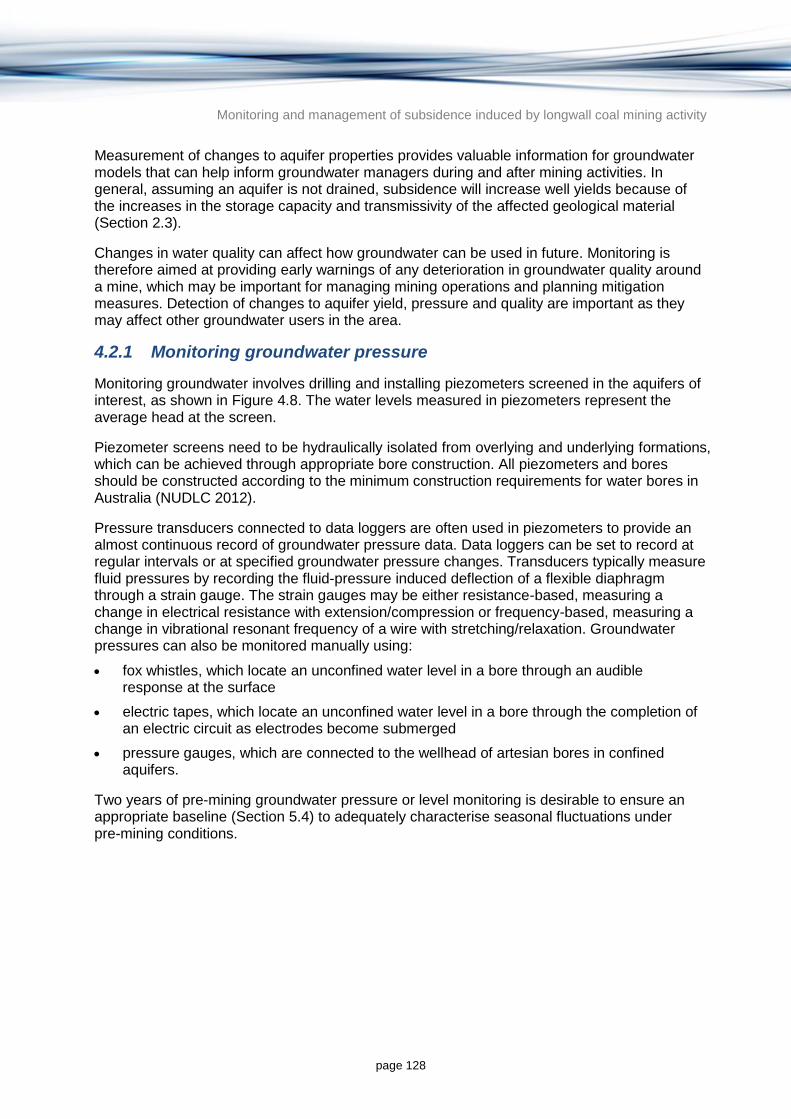
Monitoring and management of subsidence induced by longwall coal mining activity
page 128
Measurement of changes to aquifer properties provides valuable information for groundwater models that can help inform groundwater managers during and after mining activities. In general, assuming an aquifer is not drained, subsidence will increase well yields because of the increases in the storage capacity and transmissivity of the affected geological material (Section 2.3).
Changes in water quality can affect how groundwater can be used in future. Monitoring is therefore aimed at providing early warnings of any deterioration in groundwater quality around a mine, which may be important for managing mining operations and planning mitigation measures. Detection of changes to aquifer yield, pressure and quality are important as they may affect other groundwater users in the area.
4.2.1 Monitoring groundwater pressure
Monitoring groundwater involves drilling and installing piezometers screened in the aquifers of interest, as shown in Figure 4.8. The water levels measured in piezometers represent the average head at the screen.
Piezometer screens need to be hydraulically isolated from overlying and underlying formations, which can be achieved through appropriate bore construction. All piezometers and bores should be constructed according to the minimum construction requirements for water bores in Australia (NUDLC 2012).
Pressure transducers connected to data loggers are often used in piezometers to provide an almost continuous record of groundwater pressure data. Data loggers can be set to record at regular intervals or at specified groundwater pressure changes. Transducers typically measure fluid pressures by recording the fluid-pressure induced deflection of a flexible diaphragm through a strain gauge. The strain gauges may be either resistance-based, measuring a change in electrical resistance with extension/compression or frequency-based, measuring a change in vibrational resonant frequency of a wire with stretching/relaxation. Groundwater pressures can also be monitored manually using:
fox whistles, which locate an unconfined water level in a bore through an audible response at the surface
electric tapes, which locate an unconfined water level in a bore through the completion of an electric circuit as electrodes become submerged
pressure gauges, which are connected to the wellhead of artesian bores in confined aquifers.
Two years of pre-mining groundwater pressure or level monitoring is desirable to ensure an appropriate baseline (Section 5.4) to adequately characterise seasonal fluctuations under pre-mining conditions.

Monitoring and management of subsidence induced by longwall coal mining activity
page 129
Figure 4.8 Example of a piezometer used to monitor groundwater levels and quality (Jacobs file diagram)
An alternative to a conventional screened piezometer is a vibrating wire piezometer which converts a water pressure to a frequency signal via a diaphragm, a tensioned steel wire, and an electromagnetic coil. A vibrating wire piezometer is designed so that a change in pressure on the diaphragm causes a change in tension in the wire. When excited by the electromagnetic coil, the wire vibrates at its natural frequency which changes as pressure changes cause tension changes. Vibrating wire piezometers can be directly grouted in using a bentonite-cement grout allowing multiple piezometers to be installed at different levels in the same borehole. Vibrating wire piezometers are widely used in the mining industry because of their purported stability in calibration over long durations.
Multiple piezometers at different depths at the same site are often used to determine the differences in groundwater pressure between aquifers overlying a longwall panel to identify vertical hydraulic gradients and potential for vertical groundwater movement. Subsidence

Monitoring and management of subsidence induced by longwall coal mining activity
page 130
usually results in varying piezometric responses as the mining face approaches the monitoring borehole (Section 2.3). Vibrating wire piezometer strings grouted into a borehole can sometimes cease to operate as they snap off sequentially in the region affected by subsidence above the mined out panels. Sequential cessation of piezometer operation is sometimes used to track the rising height of caving and rock mass disturbance as mining proceeds.
More detail about the usual temporal and spatial change in groundwater pressures around a longwall coal mine and the groundwater mechanisms involved can be found in Section 2.3.
4.2.2 Monitoring groundwater quality
Groundwater quality monitoring can also provide valuable information on pre-mining conditions and impacts of mining subsidence. Significant groundwater quality changes can signal the connection between previously unconnected aquifers with different groundwater quality characteristics. Similarly, subsidence and fracturing of geological material overlying the mine may create pathways for surface waters to enter the aquifer. Groundwater quality monitoring is often undertaken for reasons other than subsidence impact assessment, especially in situations where mine dewatering and disposal of pumped water is required.
The most common parameters used to characterise groundwater quality include salinity (either as EC or TDS as a proxy), pH and major cations and anions. In most cases these parameters are sufficient to indicate water quality changes. If groundwater contamination is a risk, it may be analysed for more complex analytes such as metals, pesticides and organochlorides.
Groundwater samples are usually obtained from bores that are designed to be exposed (using a screen or interval of slots cut in the casing) to water from a specific aquifer or geological unit. When sampling groundwater bores, it is vital to ensure a representative sample of the aquifer is obtained. There are two accepted methods for sampling groundwater in Australia (Sundaram et al. 2009):
purging method: the stagnant or standing water resident in the borehole is removed from the bore drawing water through the screens from the aquifer. The generally accepted standard is for three casing volumes to be expelled before a representative sample can be taken (e.g. Sundaram et al. 2009)
low flow method: water is extracted through the bore screen (or screened interval) at a low rate without disturbing the stagnant water column above. This is achieved by pumping at a rate which results in minimal drawdown of the water level in the bore. Less time is required for sampling using this method.
Changes in the chemical signature of groundwater samples can be used to determine if mixing between aquifers has occurred. The ratios of various cations and anions in any one aquifer are often reasonably constant and any changes in these ratios can signal mixing with waters originating from previously disconnected aquifers. One method to highlight this change is to use a Piper diagram (Piper 1953) to plot the ratio of various cations and anions (typically calcium, magnesium, sodium, potassium, sulphate, chloride, carbonate and hydrogen carbonate). An example of a Piper diagram is shown in Figure 4.9.
When plotted on a Piper diagram, waters of a similar origin tend to cluster providing a chemical ‘signature’ of those waters. Mixing of these waters can be identified when these clusters merge. Such an analysis requires samples to be collected and analysed pre-mining to provide the baseline chemistry for comparison with post-mining results. Ideally, a number of samples collected from a variety of locations from the one aquifer are required to develop meaningful results.
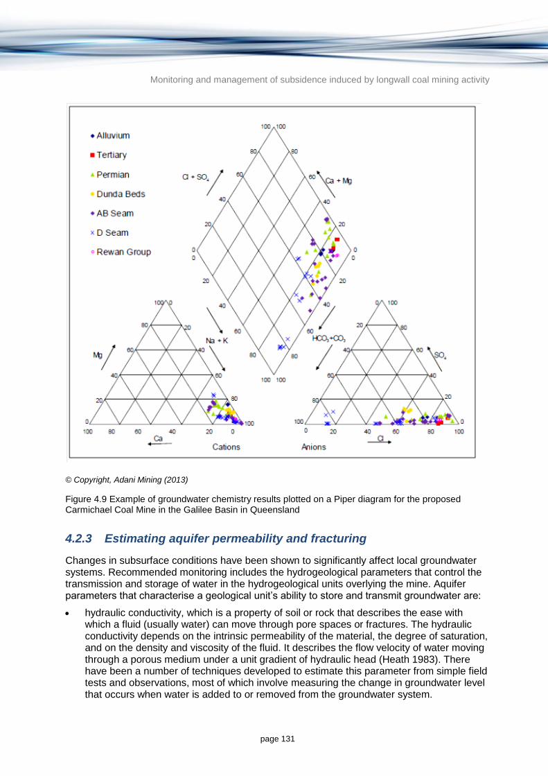
Monitoring and management of subsidence induced by longwall coal mining activity
page 131
© Copyright, Adani Mining (2013)
Figure 4.9 Example of groundwater chemistry results plotted on a Piper diagram for the proposed Carmichael Coal Mine in the Galilee Basin in Queensland
4.2.3 Estimating aquifer permeability and fracturing
Changes in subsurface conditions have been shown to significantly affect local groundwater systems. Recommended monitoring includes the hydrogeological parameters that control the transmission and storage of water in the hydrogeological units overlying the mine. Aquifer parameters that characterise a geological unit’s ability to store and transmit groundwater are:
hydraulic conductivity, which is a property of soil or rock that describes the ease with which a fluid (usually water) can move through pore spaces or fractures. The hydraulic conductivity depends on the intrinsic permeability of the material, the degree of saturation, and on the density and viscosity of the fluid. It describes the flow velocity of water moving through a porous medium under a unit gradient of hydraulic head (Heath 1983). There have been a number of techniques developed to estimate this parameter from simple field tests and observations, most of which involve measuring the change in groundwater level that occurs when water is added to or removed from the groundwater system.

Monitoring and management of subsidence induced by longwall coal mining activity
page 132
storage coefficient ‒ the specific storage, storativity, specific yield and specific capacity are physical properties that characterise the capacity of an aquifer to store and release water. They are sometimes referred to as ‘storage properties’ and are often determined from field tests (e.g. pumping tests) and laboratory tests on aquifer material samples.
In most non-mining developments, the aquifer hydraulic conductivity and storage coefficient are unchanged by development. However in longwall coal mining situations, caving and the resultant subsidence can affect the hydraulic conductivity and storage coefficient, and therefore the capacity of the aquifer to store, transmit and yield water. Monitoring changes in hydraulic parameters is important to test the assumptions used in groundwater modelling predictions.
Down-hole rock mass permeability testing (Lugeon testing) before and after mining has been used as a measure of mining induced fracturing in hard rock aquifers and permeability changes since the mid-1970s. The method involves water injection from a section of borehole (usually 3 to 6 m) sealed off above and below by inflatable packers. Large water losses indicate the presence of one or more open fractures in the test interval. One drawback of the test is that usually the equipment cannot maintain sufficient flow where the fractures are more than a few millimetres wide, whereas some subsidence delaminations can open to more than 200 mm. Water losses beyond the capacity of the pump can however be an important finding.
Monitored changes in water level over time and the rate of water injection can be used in various pumping test solutions (e.g. Theis 1935) to calculate aquifer permeability. A more detailed discussion of aquifer permeability calculation from pumping tests can be found in CSIRO and SKM (2013). Permeability is expressed as hydraulic conductivity or transmissivity (hydraulic conductivity multiplied by the aquifer thickness). Aquifer storage coefficient estimates can only be made if water level information is also monitored in non-pumped observation bores during the test. In most situations Lugeon tests do not include observations in monitoring boreholes to allow calculation of the aquifer storage coefficient.
Lugeon testing in hard rock aquifers may be supplemented by borehole camera surveys. Under ideal conditions (i.e. when the borehole is filled with clear water) the location, attitude and aperture of each fracture—whether a natural joint or a subsidence induced crack – can be recorded. This technique is more expensive than water injection and the device cannot be used in a dry hole or where there is any risk of it jamming in the bore during deployment.
Other pumping test techniques are also available to determine aquifer properties, although these are not commonly used in longwall mining situations. For example, temporary pumps can be installed in bores and used to pump water out at a constant rate while monitoring the changes in water level in the pumped bore. As with Lugeon testing, various pumping test solutions are available to calculate the hydraulic conductivity of the aquifer (CSIRO & SKM 2013).
4.3 Surface water monitoring
This section explores and evaluates the techniques for monitoring surface water resources affected by longwall coal mine subsidence including changes in geomorphology, water quality and flow. Although the section touches on monitoring program design, a more thorough analysis is provided in Section 5.4.
The review of longwall mining impacts (Section 2) identified several pathways for subsidence impacts on surface waters. Subsidence in bedrock systems can cause cracking of the streambed with subsequent loss of stream flow via increased infiltration (Section 2.4). In
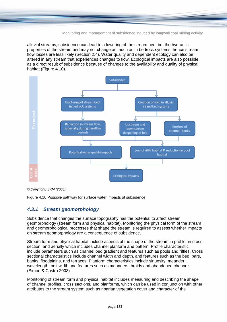
Monitoring and management of subsidence induced by longwall coal mining activity
page 133
alluvial streams, subsidence can lead to a lowering of the stream bed, but the hydraulic properties of the stream bed may not change as much as in bedrock systems, hence stream flow losses are less likely (Section 2.4). Water quality and dependent ecology can also be altered in any stream that experiences changes to flow. Ecological impacts are also possible as a direct result of subsidence because of changes to the availability and quality of physical habitat (Figure 4.10).
© Copyright, SKM (2003)
Figure 4.10 Possible pathway for surface water impacts of subsidence
4.3.1 Stream geomorphology
Subsidence that changes the surface topography has the potential to affect stream geomorphology (stream form and physical habitat). Monitoring the physical form of the stream and geomorphological processes that shape the stream is required to assess whether impacts on stream geomorphology are a consequence of subsidence.
Stream form and physical habitat include aspects of the shape of the stream in profile, in cross section, and aerially which includes channel planform and pattern. Profile characteristic include parameters such as channel bed gradient and features such as pools and riffles. Cross sectional characteristics include channel width and depth, and features such as the bed, bars, banks, floodplains, and terraces. Planform characteristics include sinuosity, meander wavelength, belt width and features such as meanders, braids and abandoned channels (Simon & Castro 2003).
Monitoring of stream form and physical habitat includes measuring and describing the shape of channel profiles, cross sections, and planforms, which can be used in conjunction with other attributes to the stream system such as riparian vegetation cover and character of the

Monitoring and management of subsidence induced by longwall coal mining activity
page 134
boundary sediments to infer dominant trends in channel processes and response and changes in physical habitat. Selection of monitoring techniques should be based on consideration of what parameter measurements will be useful for quantifying changes in channel form and processes (i.e. flow hydraulics, sediment transport and bank stability) or provide diagnostic information on active channel processes that may be influenced by subsidence (Simon & Castro 2003).
Longitudinal profile surveys can provide important field information on stream form and subsidence related impacts. Bed slope, energy-grade lines, bed features, residual pools, flow obstructions, erosion knickpoints and gradient changes can be identified. This information can be combined with cross sectional data to estimate flow velocity, discharge, stream power, flow resistance, shear stress and sediment transport. Generally a long profile will start at a stable point in the channel, and the type of geomorphic surfaces (e.g. pools, riffles, headcuts) that are encountered during a survey should be noted as well as any observable subsidence impacts (i.e. cracking, stepping).
Cross section surveys provide information on channel width and depth, wetted perimeter, bank height and angle, as well as the presence, elevation and extent of floodplain and adjacent terraces. Other attributes that can be derived from a cross-section survey include cross-sectional area, average depth, hydraulic radius and width to depth ratios. These values can be combined with longitudinal and hydraulic data to calculate channel velocity and discharge, stream power, shear stress and discharge. Generally cross-section surveys should start on the floodplain/low terrace interface and proceed across the floodplain, down the bank and across the channel finishing on the opposite side of the valley. Sufficient detail should be provided to clearly define floodplain topography, bank form, edge of water, thalweg and any bar surfaces (Simon & Castro 2003).
Other monitoring techniques that can be used to identify changes in channel form and process include erosion pins, sediment quadrats, repeat sediment sampling, monitoring of sediment loads and repeat photographs. Erosion pins are made up of pieces of reinforcing bars and can be inserted into a channel surface (i.e. bed or bank) and monitored over time to record erosion and deposition. Sediment quadrats can be used to monitor qualitative changes in substrate. Particle size distribution analysis can provide more accurate assessment of substrate characteristics. Suspended and bed load sample analyses can improve understanding of sediment transport rates. Repeat photographs of the channel environment from fixed monitoring points can identify changes in channel form and physical habitat.
Depending on the level of accuracy required, a range of survey techniques may be used to monitor changes in stream form. Remote sensing may be suitable in open areas, but may not be suitable in densely vegetated areas and areas of channel where water ponding occurs. A total station or laser level is recommended for ground surveys of cross-sections and longitudinal profiles. A review of longwall mining operations and stream networks in the affected areas should be undertaken to select of survey techniques and inform decisions regarding the extent and frequency of survey required. Ideally the survey should cover the period before longwall mining commences and be repeated at regular intervals to assist in identifying changes (Simon & Castro 2003).
Changes in channel planform can be monitored using aerial photographs and maps. Measurements of channel planform include the number of active channels, sinuosity, meander belt width, meander amplitude, radius of curvature and valley width. Measuring planform changes over time can provide information on variability in the system and potential rates and magnitude of change that may be expected to occur in future (Simon & Castro 2003).

Monitoring and management of subsidence induced by longwall coal mining activity
page 135
Monitoring programs should be developed with consideration to the geomorphology of the watercourse and the range of possible subsidence related impacts to stream form and physical habitat. Examples of different geomorphological environments and the type of monitoring that may be required to monitor changes in stream geomorphology in bedrock and alluvial systems and swamp environments include:
bedrock systems: may require survey and measurement of bed cracks, longitudinal profiles to identify changes in grade and formation of steps, repeat survey of channel form to identify relationships between surface flow and water level along the stream
alluvial systems: may require longitudinal and cross-section surveys to monitor changes in channel form and process activity (e.g. bank erosion, channel deepening, migration of knickpoints). This information can be linked with hydraulic data to quantify changes in velocity, stream power, potential sediment transport, or other required parameters
swamps: may require longitudinal surveys to measure changes in slope, particularly erosion knickpoints. Cross-sections and broader feature surveys of swamp morphology, noting changes in topography and extent of bare and vegetated areas over time.
4.3.2 Stream hydrology
Subsidence that fractures streambeds has the potential to reduce stream flow. Stream flow monitoring is required to determine any stream losses as a consequence of subsidence.
Stream flow can be quantified in a number of ways (Ladson 2008):
direct measurement of discharge (measuring the change in volume of water over time)
direct flow measurement at a purpose-built structure where depth of water flowing through or over a structure (e.g. a V-notch weir) can be related to discharge
relating water surface slope and flow area to discharge
relating water velocity and flow area to discharge
dilution gauging, where a known concentration of chemical tracer is added to the stream flow and the diluted concentration is determined at some point downstream
acoustic Doppler flow measurement techniques.
The above methods provide a measurement or estimate of discharge at a point (or interval) in time, and need to be measured over time to understand natural daily and seasonal variation. A time-series record of stream flow can be obtained by simple depth measurements using a stage rating curve that relates water depth to discharge at a stable cross-section, such as a location where there is a natural control or at a constructed weir (Ladson 2008). Stage discharge relationships (called rating curves) are established by measuring discharge and depth on many occasions over a range of discharges (from low to high), which then allows discharge to be calculated from depth measurements alone. Depth can be more cheaply and remotely monitored using a variety of sensors (e.g. pressure sensors, shaft encoders and capacitance probes) and recorded on a data logger (Ladson 2008). Stream flow gauges should be rated for the range of flows expected to occur. As stream flow can change on a daily basis a daily time-series of stream flow measurement is required, in smaller streams sub-daily intervals may be required (e.g. hourly or even every 15 minutes).
Gauging stations need to be installed at the upstream and downstream ends of a reach to establish if the reach is gaining or losing water (Ladson 2008). If the downstream volume is less than the upstream volume then the reach may be losing water to groundwater,

Monitoring and management of subsidence induced by longwall coal mining activity
page 136
evaporation or pumping for human use. If the outflow volume is greater than the inflow volume then the reach may be gaining water from groundwater inflow, tributary inflow, local surface runoff and/or direct rainfall.
Streams exhibit naturally occurring patterns of gains and losses depending on a range of factors, including permeability of the streambed, groundwater levels and topography (Ladson 2008). The pattern of gains and losses to a reach should be determined prior to any potential impact as a part of baseline monitoring so that a comparison of gaining and losing patterns before and after the period of impact can be made. If subsidence has caused an increase in the permeability of the streambed (e.g. through fracturing bedrock) the stream is likely to demonstrate a loss of stream flow; either an increased rate of loss, a decrease in the pre-mining rate of gain, or in extreme circumstances a reversal of gaining to losing characteristics.
When establishing stream flow gauging locations it is also necessary to consider tributary inputs, rainfall and evaporation in the water balance modelling. Water balances should be determined for a range of flow conditions to establish if there are circumstances where losses are more critical (e.g. during low flow periods when changes are relatively more significant). Losses during low flow periods are likely to be ecologically important because decreased stream flow can result in deterioration in water quality and loss of access to habitat for macro-invertebrates and fish.
4.3.3 Water quality
Subsidence can affect water quality as a result of changes in stream flow. Changes in water quality result from changes in groundwater and surface water interaction which may result in the release of chemicals and gases to the water column from underlying aquifers and coal seams, and also through erosion of the streambed which may contribute increased sediment load and turbidity to the water column. Water quality impacts will be site-specific and be related to the nature of the groundwater and surface water interaction, geomorphology, topography and stream flow (Chapter 2).
The ANZECC and ARMCANZ (2000a) water quality guidelines define water quality variables as stressors (e.g. suspended solids, turbidity, salt, dissolved oxygen, nutrients) and toxicants (e.g. heavy metals, hydrocarbons). The general impacts on environmental values (e.g. fish health) and beneficial uses (e.g. irrigation, primary contact recreation) of various stressors and toxicants is well documented and guidelines have been developed at the national level that cover a wide range of potential stressors and toxicants (ANZECC & ARMCANZ 2000a). Some states have developed state-based guidelines (e.g. Queensland (DERM 2009), Victoria (Victorian EPA 2003a)) or regional guidelines (DERM 2011; Rogers et al. 2011), often using the process described in ANZECC and ARMCANZ (2000a) for deriving regional trigger levels, or defaulting to ANZECC guidelines for some stressors and/or toxicants (e.g. in NSW).
However, most guidelines have been developed for perennial streams and may not be applicable for the ephemeral waterways, which occur in many areas where longwall coal mining occurs in Australia, particularly in the Surat and Bowen Basins in Queensland and northern NSW. Furthermore, there may be coal-specific stressors and toxicants for which there are no guidelines, or for which data is insufficient to determine a guideline.
Water quality variables to be monitored should be determined on a case–by–case basis and be informed by a review of potential impacts at the site scale. Standard methods for water quality sampling and analysis are well established and include field-based measurements (e.g. temperature, salinity, dissolved oxygen, turbidity) and sampling for later laboratory

Monitoring and management of subsidence induced by longwall coal mining activity
page 137
analysis (e.g. nutrients, heavy metals and other toxicants). Sampling techniques are not further described here but are described in Commonwealth of Australia (2014).
In accordance with a before-after-control-impact (BACI) monitoring approach (Section 5.4 and Downes et al. 2002), water quality monitoring should be established in potentially affected areas prior to any impact occurring to benchmark current conditions. Sampling locations should be included upstream and downstream of potential impact sites and also at control or reference sites in areas where no impact is expected. Water quality objectives must be determined and management actions identified that are to be implemented in the event that water quality objectives are exceeded. Objectives should be generally consistent with the appropriate state or territory guidelines or, when these are not available, the national guidelines (ANZECC & ARMCANZ 2000).
Sites and sampling frequency depend on the nature of variability in the various indicators being measured and also on the statistical techniques used for analysis. Most water quality guidelines prescribe that a minimum of monthly sampling be undertaken for benchmarking purposes (e.g. ANZECC & ARMCANZ 2000b; Victorian EPA 2009). More frequent sampling may be required depending on site specific issues, e.g. continuous monitoring of dissolved oxygen, temperature or EC may be required during low flow periods when risks to aquatic ecosystems are greatest from high temperature and low dissolved oxygen.
Standard analysis of variance (ANOVA) statistical techniques can be used to determine if there are any significant differences in water quality before and after impacts and between impact and control sites, and for comparison against agreed guidelines.
Monitoring and management of subsidence induced by longwall coal mining activity
page 138
5 Generic approach for investigating subsidence related impacts on groundwater and surface water resources
This section outlines a generic approach for investigating longwall coal mine subsidence. The approach provides suggestions to proponents and regulators on the appropriate components and sequence of investigation, spanning the life of a mine (from exploration through to pre-feasibility, feasibility, and production to rehabilitation, closure, and post-mining management).
A flow chart summarising stages in the proposed approach is shown in Figure 5.1. Each step in the flow chart is discussed below. Although most of the steps are sequential, there are potential iterative parts of the process such as Steps 4, 5, 6 and 7 as shown in Figure 5.1.
Every site will be different and it may not be possible or feasible to undertake all steps shown in Figure 5.1 but the approach includes a logic that will evaluate and quantify the risks of subsidence and its associated impacts on groundwater and surface water resources. Using the approach may provide a necessary level of confidence to the proponent, regulator and the community that the impacts on groundwater and surface water resources have been thoroughly assessed.
The approach is streamlined and appropriate for all types of groundwater and surface water resources at risk of being affected by longwall coal mine subsidence. The approach takes a broad, assets-based approach and tailors the effort and focus towards identified assets. That is, complex and expensive modelling exercises can be avoided if there are no high value water resource assets in the potential area of influence of a mine, or if the assets have a very low risk of being adversely affected. As such, the approach ensures that the complexity, time and expense of the investigation remains commensurate with the level of potential risk and the economic, social, and environmental value of the assets.
Although this generic approach is focussed on impacts on groundwater and surface water resources, it could be expanded to include other assets such as water dependent ecosystems, land assets or infrastructure.

Monitoring and management of subsidence induced by longwall coal mining activity
page 139
Figure 5.1 Flow chart for investigating the impacts of longwall coal mine subsidence on groundwater and surface water resources
Step 1 Identify and conceptualise water resource
assets
Step 2 Characterise the assets and determine
their management objectives
Step 3 Qualitative risk assessment
Step 4 Baseline monitoring
Step 5 Conceptual model development
Step 6 Quantitative estimation of subsidence
Step 7b Quantitative estimation of subsidence
impact on surface water resources
Step 7a Quantitative estimation of subsidence
impact on groundwater resources
Step 8 Quantitative risk assessment
Step 9 Mitigation measures and adjustment of
risk assessment
Step 11 Validation of predictions
Step 10 Post-mining monitoring

Monitoring and management of subsidence induced by longwall coal mining activity
page 140
5.1 Step 1: Identify water resource assets
Natural and infrastructure assets should be identified for the region in and around the area of longwall coal mining and an asset inventory should be created. The area of asset identification should include a suitable buffer zone around the proposed mine extent and should include connected groundwater and surface water resources. Assets to be identified include:
aquifers
streams, rivers and creeks
water infrastructure such as dams, pipelines, canals, and aqueducts
wetlands and springs
groundwater dependent ecosystems not covered above
ecological assets potentially affected by changes to groundwater and surface water resources (e.g. aquatic flora and fauna or stygofauna)
infrastructure such as buildings, roads and bridges.
One criterion for listing in the asset inventory may be whether they have a social, economic or environmental value. E.g. aquifers with a reasonable yield and quality parameters or with strong environmental values due to the connection with surface water systems would be included in the inventory. ANZECC and ARMCANZ (2000a, Vol. 1) uses the term ‘environmental value’ in preference to the previous term ‘beneficial use’ to describe the values of water dependent assets which include:
aquatic ecosystems
primary industries (irrigation and general water uses, stock drinking water)
aquaculture and human consumption of aquatic foods
recreation and aesthetics
drinking water
industrial water
cultural and spiritual values.
A starting point for identifying water resource assets with high environmental value is the Commonwealth Matters of National Environmental Significance as defined under the Environment Protection and Biodiversity Conservation Act 1999. Any water resource asset listed as having national environmental significance should score highly on environmental value. Similarly any state-based registers of environmental significance should also be consulted.
If there is little existing information about an identified asset, there may be a need for targeted monitoring or to conduct additional investigations to acquire the data necessary to undertake an assessment of an asset’s significance.
Monitoring and management of subsidence induced by longwall coal mining activity
page 141
5.2 Step 2: Characterise the assets and determine management objectives
5.2.1 Initial data collection
This step involves collecting basic geotechnical, groundwater and surface water data to initially assess risks to the assets and identify knowledge gaps (Step 3). This step is likely to include a mixture of desktop evaluation of existing data and analysis of data collected during the exploration phase (e.g. drilling).
Basic information collected at this stage may harvest information from local or regional studies or exploration drilling, and may include:
target seams
depth of cover
area to be mined, mining method and mining configuration
geotechnical data on the seams to be mined or overburden with specific emphasis on: intact rock strength and deformability; rock mass (bulk) properties; type, spacing and orientation of geological discontinuities (e.g. bedding, joints).
.Groundwater data collection should include existing or readily collectable information on:
hydrostratigraphy
groundwater levels, pressures, fluxes, and water quality
hydraulic properties (e.g. hydraulic conductivity and storativity)
groundwater use.
Data collection for surface water assessments may include the following information:
topography, catchment land use information and hydrologic characteristics
climate data: rainfall, evaporation, stream flow records, stream hydraulic characteristics
water quality records, environmental values, water quality guidelines
river health assessment results and other bio-assessment data
geochemical assessments of groundwater discharge sites
stream geomorphology characteristics, bed load and suspended load assessments.
5.2.2 Determining management objectives
Once assets are identified and initial data collection has been completed, assets can be characterised and possible impacts assessed by:
determining environmental values to be protected and their required levels of protection
identifying environmental concerns including possible changes to groundwater levels and quality, or changes to surface water flow, quality or geomorphology. Given the lack of quantitative predictive information, this is likely to be a broad qualitative assessment of possible impacts
identifying other ‘off tenement’ anthropogenic and natural factors also affecting groundwater and surface water assets.

Monitoring and management of subsidence induced by longwall coal mining activity
page 142
The Australian and New Zealand guidelines for fresh and marine water quality 2000 (ANZECC & ARMCANZ 2000a, Vol.1) suggests that water quality objectives are:
‘…the specific water quality targets agreed between stakeholders, or set by local jurisdictions, that become the indicators of management performance’.
For the purposes of this approach, this should be broadened from just water quality objectives to water management objectives in general. At this stage, regional, state and national groundwater and surface water management plans should be examined to determine any existing agreed management objectives for identified assets. Consultation should be undertaken with the relevant state, territory and Commonwealth agencies regarding management objectives for identified assets.
5.3 Step 3: Qualitative risk assessment
This step identifies potential constraints to the mining proposal by identifying knowledge gaps and risks to identified assets. Information collected in Step 1 and the geotechnical characteristics (Step 2) should be analysed to determine knowledge gaps. Important knowledge gaps should either be addressed at this point or in the baseline monitoring program (Step 4).
A qualitative risk assessment should be undertaken to determine the significance of the subsidence risk to the assets identified in Step 1. Standards Australia’s (2009) risk management guidelines detail a number of steps for the risk assessment process which are summarised below.
As part of this step, the organisation should establish internal and external communication and reporting mechanisms to support and encourage accountability and ownership of risk (Standards Australia 2009). This may involve the development of a steering group for the works including relevant representatives of State and Federal Government regulators.
5.3.1 Risk identification
This step involves identifying the potential for subsidence to impact on the assets identified in Steps 1 and 2 including groundwater, surface water, ecological and infrastructure assets. Only potential impacts which have almost no likelihood of occurring should be eliminated at this stage with further prioritisation occurring in later stages.
5.3.2 Risk analysis
Risk analysis involves identifying the causes and sources of risk, their likelihood, the positive and negative consequences and associated risk management processes (Standards Australia 2009). Factors that affect consequences and likelihood of an adverse impact should be identified. Risk is analysed by determining consequences and their likelihood, and other attributes of the risk. Existing or potential controls and their effectiveness and efficiency should also be taken into account (Standards Australia 2009).
This step involves analysing the consequence and likelihood of the potential risks identified (Section 5.3.1). Likelihood assessment may be either qualitative or a simple quantitative modelling exercise using either empirical or analytical modelling techniques, and the complexity of analysis should be commensurate with the data available. Detailed quantitative analysis of subsidence and impacts occurs at a later step.

Monitoring and management of subsidence induced by longwall coal mining activity
page 143
Consequence assessment is tied to the value of each identified asset and the possible impact subsidence may have on that value. E.g. an aquifer with strong potential for use may have that potential degraded by either a reduction in yield or quality, or both.
Likelihood and consequence assessments should be combined to develop a risk rating for each of the identified assets. An example of how these parameters could be combined is shown in Figure 5.2.
© Copyright, Standards Australia (2009). A to E is increasing likelihood, 1 to 5 is increasing consequence and V to I is increasing risk
Figure 5.2 Example of a risk rating table for combining likelihood and consequence ratings
The risk assessment phase will influence subsequent monitoring (Step 4) and the focus of the conceptual and numerical model development (Steps 5, 6 and 7) so it is important that the degree of uncertainty in consequences and likelihoods is reflected in the risk assessment. A likelihood or consequence evaluation with a high degree of uncertainty should have a higher risk rating than if the evaluation were more certain. In any qualitative rating of likelihood and consequence, it is important to also assign a confidence rating—which could be as simple as a high, medium or low rating or plus or minus figures if it is possible to estimate. Where more detailed modelling information is available, an appropriate method of confidence rating is provided in the Australian Groundwater Modelling Guidelines (Barnett et al. 2012) and in Section 3.2.6.
5.3.3 Risk evaluation
Risk evaluation assists in making decisions based on the outcomes of risk analysis about which risks need treatment, and the priority for treatment (Standards Australia 2009). In the initial qualitative risk assessment, a decision is required on which risks against which assets require further evaluation. The precautionary principle is best applied in situations where either or both of the likelihood or consequence has a high degree of uncertainty. In other words, a higher risk rating should be applied in situations of higher uncertainty.

Monitoring and management of subsidence induced by longwall coal mining activity
page 144
Risk ratings identify important assets and focus the rest of the investigation on those assets. The scope of further investigation is very much influenced by this initial risk assessment. In the case where there are few or no significant groundwater and surface water assets and the likelihood of subsidence impact is low, then a limited program of investigation and monitoring should be undertaken to confirm the findings of the initial risk assessment. Conversely, if there are high value assets present which have a strong likelihood of impact, a thorough investigation program involving intensive baseline monitoring and modelling to a high confidence level is required.
5.3.4 Identification of knowledge gaps
The initial risk assessment is likely to identify a number of knowledge gaps. Uncertainty can be reduced by collecting additional information, but knowledge gaps need to be prioritised based on their importance to the risk assessment. Knowledge gaps will influence the monitoring program (Step 4), the development of conceptual models (Step 5), and the quantitative assessment of subsidence impacts (Step 6).
5.4 Step 4: Baseline monitoring
A baseline monitoring program is required to collect geotechnical, hydrogeological and hydrological data suitable for:
establishing pre-mining baseline conditions so future impacts can be assessed
undertaking quantitative predictions of subsidence and its impact
decreasing the uncertainty in the risk assessment conducted in Step 3
determining if the management objectives determined in Step 2 are being achieved.
Baseline monitoring must be able to establish benchmark conditions against which future impacts can be detected (Step 10). A multiple before-after-control-impact (MBACI) design is recommended (ANZECC & ARMCANZ 2000b; Downes et al. 2002), which samples multiple control or reference sites and multiple impact sites prior to and after a predicted disturbance and tests whether relevant variables change. The use of multiple control and impact sites increases ability to detect changes and the range of natural variability to be more confidently determined. The sampling period also has an effect on the ability to detect change, especially if the change does not occur in immediate response to the disturbance (i.e. there is a lag response or a trend response rather than a step change). The MBACI approach uses standardised multivariate analysis techniques to statistically evaluate differences between sites before and after impact.
Using the MBACI approach, the specific objectives of baseline monitoring are to:
characterise environmental condition; which is critical for defining value as part of the next phase of risk assessment, for helping to identify acceptable levels of impact, and for selecting the most appropriate variables for more detailed impact monitoring
establish the magnitude of natural spatial and temporal variability at a range of scales; which is necessary for informing the selection of control and impact sites, and defining monitoring frequency.
Baseline monitoring should be undertaken at a range of sites that are within a predicted area of impact, as well as sites outside the area of impact that can be used as control or reference sites. The number of control sites needed depends on the degree of variation in selected variables; the greater the variability the more sites that are required to quantify variability.

Monitoring and management of subsidence induced by longwall coal mining activity
page 145
Choice of measurement parameters depends on the values assigned to each asset, and therefore on the objectives of the study (ANZECC & ARMCANZ 2000b). For the baseline (pre-impact) component of the monitoring program to detect changes resulting from subsidence, the following parameters should be considered:
water levels and groundwater quality within and above the zone of mining
aquifer hydraulic properties (e.g. hydraulic conductivity and storage coefficient)
water quality and biological variables in surface waters
natural surface elevation in and around the area of mining
wetland and groundwater dependent ecosystem condition and hydrology
groundwater discharge geochemical processes
stream erosion and sediment transport.
Throughout baseline monitoring, indicators should be evaluated for their suitability to:
help determine physical and environmental condition
be responsive to disturbance in a predictable way, especially subsidence related disturbance.
After any observed impacts have occurred, the suite of monitoring indicators could be reduced to those that are known to respond to specific disturbances.
The frequency of sampling and length of monitoring of each indicator depends on its response time. Water levels should be monitored continuously because water level can change on a daily basis, whereas erosion extent may only need to be monitored once per year or season because it responds much more slowly.
Baseline monitoring should commence at least 2 years prior to any activity that may cause subsidence, which is the minimum recommended time required to adequately describe baseline water quality conditions (ANZECC & ARMCANZ 2000a). If monitoring shows no change after a few years it may be assumed that impacts will not occur and the monitoring program may be reduced. Conversely, if the response continues for many years, monitoring should continue until a steady state can be demonstrated.
In the case of potential wetland disturbance, ecological character descriptions for wetlands using the National Framework and Guidance for Describing the Ecological Character of Australian Ramsar Wetlands (DEWHA 2008) may be used to obtain baseline information. The ecological character description of a wetland provides the baseline description at a given time, which can be used to assess change in the ecological character of these sites (DEWHA 2008). It provides information about the environmental features and services of the site and forms the reference for the following activities (DSEWPaC 2013a):
developing and implementing a management plan to maintain the ecological character of the site
designing a monitoring program to detect change in ecological character
reporting any changes in the ecological character of internationally significant Ramsar sites
assessing the likely impact on ecological character of proposed actions, including that required under the EPBC Act 1999.
Monitoring and management of subsidence induced by longwall coal mining activity
page 146
Baseline information can be used in the risk assessment framework that uses likelihood of impact and consequence of ecosystem loss to prioritise locations for protection (Step 3), and hence the amount of monitoring required.
Methods for monitoring surface and subsurface subsidence and the impacts on groundwater and surface water were discussed and evaluated in Section 4.
5.5 Step 5: Conceptual model development
Developing a clear understanding of the systems and interactions occurring in the subsurface strata, aquifers and surface water features is a necessary precursor to quantitative analysis of their likely behaviour under mining conditions. The focus of investigations should be commensurate with the risks identified in Step 3. If a particular aquifer is at risk, it is important to understand the hydraulic properties of the aquifer and its interaction with other aquifers and aquitards in the region. Conceptual modelling requires characterising the geotechnical behaviour of the strata to be mined and its interburden and overburden. The need to characterise groundwater and surface water systems is dependent on whether the risk assessment process identifies them as being potentially affected and of sufficient value to warrant further attention.
Conceptual models are commonly illustrated using diagrams that use symbols or drawings to represent the ecological system to communicate linkages between system components or processes (DEWHA 2008). They need to be as simple as possible yet still capable of depicting key ecosystem components: in this case subsidence processes; environmental values; and ecosystem assets, values, and services. They provide a useful and easy to understand tool for organising and communicating knowledge, identifying knowledge gaps, aid decision making and planning, and facilitate wider participation among the community (DEWHA 2008).
Monitoring data (Step 4) is an important input to this process in addition to the initial information (assets; Steps 1, 2 and 3). Some of the issues to be identified in the conceptual models are described below.
5.5.1 Geotechnical conceptual model
Geotechnical conceptual models draw together a range of information, which normally represents a cross-section along the panel centre line. Such models are a representation rather than an exact model of the centre line overburden profile. E.g. it might incorporate a fault that is not actually present, but whose effects on the subsidence profile it is desired to simulate. Likewise a few major joints may be represented by discrete elements in the model, but the majority of the joints will be considered merely as weakening elements within layers (‘intrinsic joints’), and hence represented by strength reduction factors.
Generalised geological layering above the proposed longwall panel or group of panels is developed, based on stratigraphic information obtained from the closest exploration boreholes. It is important to distinguish between massive strata (such as sandstones or conglomerates) which do not cave easily, and thinly bedded lithologies such as shale or mudstone which cave readily.
Geotechnical logging now needs to be more detailed than that needed for coal exploration, with much more attention paid to the degree of fracturing in the overburden rock mass. At least one fully cored and tested geotechnical borehole should be drilled in the vicinity of the panel. In a new area this might be positioned over the centre of the panel, be equipped with a multi-anchor extensometer and subsequently be used to monitor subsidence in the overburden as

Monitoring and management of subsidence induced by longwall coal mining activity
page 147
the longwall face passes beneath the borehole. The geotechnical borehole, and indeed most coal exploration holes, should be geophysically logged with a combination downhole sonde so the bulk physical properties of different layers penetrated by the borehole can be compared with the lithological log. A sonic interval velocity (acoustic) log may be suitable.
Core should be photographed, samples taken for laboratory testing and on-site point load strength testing should be performed on the remaining core sticks. Logging and sampling should be done as soon as possible after drilling to avoid the effects of stress relief, de-gassing, drying and core deterioration. Core samples should be carefully wrapped and sent to an appropriate geotechnical testing laboratory. Testing should include uniaxial compressive strength (UCS), tensile strength, elastic modulus and density, plus specialised tests as required.
Borehole cameras can gather detail on the location and orientation of geological discontinuities, especially joints. In some cases the geotechnical borehole may recover coal seam samples for gas desorption tests to assist with design of face ventilation.
Local geological structures that are likely to affect subsidence behaviour should be assessed. Gross structures (major faults, dykes and sills, steep bedding) which might affect the viability or the alignment of the longwall panel should be investigated first. Less conspicuous properties such as the spacing, tenacity and persistence of bedding; and the spacing, continuity and orientation of lesser joints should also be understood. These features may be investigated by a combination of surface outcrop mapping, image interpretation, borehole log observations, and by drawing on local mining experience.
5.5.2 Groundwater conceptual model
Hydrogeological conceptualisation should include specific aspects of the local and regional hydrogeology and hydrology that are of particular importance to the mine. The conceptual model should include the individual coal seams that will be mined both in the mine footprint and elsewhere throughout the domain of interest. While many of the seams may be relatively thin and insignificant in terms of their hydrogeological influence, it is useful to include individual seams so that the mine plan can be clearly represented in the predictive scenarios.
The conceptualisation should also explicitly represent the principal hydrogeological units that are present. In most cases the geological structure of the site will be well defined at the mine site because of the exploration drilling activities commonly used to define the coal resource. Information on the geostratigraphy in areas remote from the mine is usually based on sparse information and hence the hydrogeology beyond the mine may be less well known.
The pre-mining groundwater condition in the project area should be described including:
groundwater recharge and discharge mechanisms and locations
directions of groundwater flow through the study area (flow dynamics)
transmission and storage characteristics of relevant hydrogeological units
temporal variations in groundwater head (both long-term trends and seasonal fluctuations)
existing groundwater use including the location of extraction wells and metered or estimated extraction rates
interactions between overlying hydrogeological units
condition of groundwater present in each of the aquifers present.

Monitoring and management of subsidence induced by longwall coal mining activity
page 148
There should also be a clear description of the groundwater-surface water interaction processes present in the pre-mining environment, including identification of losing and gaining stream segments or reaches. Note that the pre-mining environment may already exhibit disturbance from previous, nearby mining operations.
The conceptualisation should provide a description of the anticipated changes that will occur as a result of mine operation. It is useful to identify formations and areas that are expected to be affected by geological deformation, cracking and collapse to help define which parts of the predictive model will require special boundary conditions and time-varying material properties to adequately represent the changes that will accompany mining activities.
5.5.3 Surface water and wetland conceptual models
Surface water and wetland conceptual models can vary in complexity due to the area of coverage required, the number of streams and catchments, the amount of storage, number of extractive users, and the complexity of the aquatic ecosystem and geomorphological system.
Subsidence is likely to affect surface waters through increased flood extents, reduced flow during low flow events, increased loss of water to groundwater through surface cracking, changes to water quality from increased exposure of geochemically reactive surfaces, and increased fluvial erosion and deposition rates. Existing conceptual models can be adapted to describe subsidence related impacts.
There is a variety of resources for developing conceptual models of surface water and wetland ecosystems, including the Queensland Government’s WetlandInfo website (DEHP 2014). A simple conceptual model for the Lockyer Creek catchment is shown in Figure 5.3.
© Copyright, DEHP (2014)
Figure 5.3 Simple conceptual model of Lockyer Creek and catchment

Monitoring and management of subsidence induced by longwall coal mining activity
page 149
The Lockyer Creek conceptual model identifies low flows, elevated erosion, poor riparian condition, agricultural impacts and clearing as major influences on water quantity and quality. It could be adapted to include subsidence related impacts by adding any of the impacts listed below.
There are several potential impacts of longwall mining on surface waters that may need to be included in conceptual models for surface waters including:
water quantity impacts
water quality impacts
geomorphological/erosion change impacts
aquatic ecosystem habitat impacts.
Water quantity conceptual models may include information such as:
hydrologic rainfall-runoff, catchment land use and flow analysis
stream hydraulic characteristics, storages, flooding, slope, substrate, stream gain/loss areas, roughness, sinuosity
sensitive receptors, downstream users, environmental flow requirements, water takes and licensing.
Water quality conceptual models may include information relating to:
biogeochemical models of nutrient cycling and sediment deposition
targeted pollutant or toxicant geochemical processes
key species and habitats, threatened species, algal production, light and thermal models.
Geomorphological and erosion conceptual models may include information on:
land use change, vegetation cover, soil types, particle size analysis
topography, erosion/transportation/deposition zones or segments, slope analysis, erosion types assessment and fluvial processes
stream flow hydrology, channel energy changes, nick points, sediment transport and deposition, substrate analysis.
Aquatic ecosystem habitat conceptual models may include:
riparian habitat biogeochemical models, land use, vegetation, edge habitat species response
benthic habitat biogeochemical models, nutrient/sediment dynamics, benthic species response
water column and hydrodynamic biogeochemical models, aquatic species response, habitat assessment.
It is important to develop a conceptual understanding of the wetland and how it might be affected if there is potential for disturbance. DEWHA (2008) provides guidance on how best to characterise wetlands and develop such conceptual models. Gross (2003; in DEWHA (2008)) described two types of models that are commonly used to conceptually represent ecological systems. The first type is a control model that depicts the major system components, drivers and feedbacks of the system. It is intended to be an accurate representation of the system at a particular level of aggregation. The second is a stressor model that is an abstraction of a

Monitoring and management of subsidence induced by longwall coal mining activity
page 150
particular system or part of a system focussed on the links between stressors, ecosystem responses, effects, and in some cases indicators. The stressor model does not incorporate all system components, feedbacks or interactions, but is useful to help determine the impact of mine subsidence. Generic conceptual models for peat swamps impacted by longwall coal mining subsidence have been developed in Commonwealth of Australia (2014).
The model is a useful visual tool that can be used to guide discussions—particularly in risk assessment workshops.
5.6 Step 6: Quantitative estimate of subsidence
For those subsidence impacts deemed to have anything other than a negligible risk in the qualitative risk assessment in Step 3, require more accurate quantitative assessment. The first step in this process is to quantify the amount of subsidence which provides important input data to quantifying the impacts on surface water and groundwater. Whether prediction of subsurface subsidence is required in addition to surface subsidence is determined by whether impacts to groundwater resources are required.
There are a variety of empirical and numerical modelling techniques available to simulate and predict the degree and timing of subsidence (Section 3.1). The methods and their advantages, disadvantages, inputs, outputs and accuracy are described in Section 3.1 along with a description of the general modelling method.
As described in Section 3.1, empirical estimates are applicable for a single seam operation where the geological sequence is known and is consistent with that contained in an empirical data base. Empirical techniques are generally regarded as providing the most accurate results in these environments and are favoured over numerical techniques by both the Queensland and NSW Governments. This is because actual subsidence mechanisms are often not fully understood and cannot be fully simulated through numerical models whereas empirical methods do not need to simulate the mechanisms. However, empirical techniques are not as applicable—if at all—where geotechnical conditions are substantially different from those used to develop the empirical techniques or the mined sequence has multiple seams. In these instances, the following approach is usually taken:
numerical modelling approaches may be used to quantify subsidence and mining induced conductivity of the overburden for sites requiring a detailed assessment
a conservative estimate based on Li (2010) may be used for sites requiring a less detailed assessment. Generally, subsidence may be assumed to be approximately 80 to 85 per cent of the total seam extraction.
5.7 Step 7a: Quantitative estimate of the impact of subsidence on groundwater resources
This step involves the development and use of groundwater flow models to predict the impacts of subsidence on groundwater. The need for groundwater modelling will depend on whether the results of the qualitative risk assessment in Task 3 identify impacts of groundwater as being a risk. Groundwater modelling can be an expensive and time consuming process and the complexity and type of modelling undertaken needs to be commensurate with the risk of impact (Step 3) and the value of the groundwater resource (Steps 1 and 2).
The types of modelling approaches and the situations most suited are described in detail in Section 3.2 along with a detailed description of modelling methodology.
Monitoring and management of subsidence induced by longwall coal mining activity
page 151
Groundwater models of longwall coal mining operations are generally aimed at:
providing information on water inflows to the underground void and hence assisting in the design of pumping and water control facilities
assessing impacts of subsidence on local groundwater and surface water resources and associated groundwater dependent ecosystems (GDEs). These impacts are largely due to the subsidence and geological deformation that occurs as a result of mining.
While it is acknowledged that most groundwater models of longwall coal mines have two quite distinct objectives (as listed above) the focus of this report and the methods described in subsequent paragraphs relate to modelling the impacts (on groundwater and surface water resources) of the subsidence and geological deformations that accompany mining.
5.8 Step 7b: Quantitative estimate of the impact of subsidence on surface water resources
The need for surface water modelling will depend on whether the results of the qualitative risk assessment in Task 3 identify impacts on surface water as being a risk. Surface water modelling can be an expensive and time consuming process and the complexity and type of modelling undertaken needs to be commensurate with the risk of impact (Step 3) and the value of the surface water resource (Steps 1 and 2).
A detailed analysis of surface water modelling methods is described in Section 3.3 along with a description of a generalised method. In addition, there are several references providing guidelines for best modelling practice for surface waters (eWater 2011a, 2011b; NWC 2012; US EPA 2009; eWater 2012).
Surface water modelling for the purposes of waterway design commonly involves the use of modified topography to some extent as stream structures, such as pools and channels, are moved or changed to facilitate better drainage or to divert clean water flows around a potentially polluting mining or other activity. In general surface water models will be calibrated with existing topography, and then run to predict future scenarios with modified topography based on subsidence predictions.
Topography is arguably the single most important input to surface water modelling in terms of predicting the future effects of predicted subsidence. Where possible the spatial area predicted to be effected by subsidence should be prepared in a three-dimensional (x, y, z) format to enable the modelling of scenarios to assess potential impacts on surface water, stream substrate, water users and storages. This will involve interaction with the geotechnical subsidence model outputs, (and modellers themselves) which may be in one, two or three dimensions depending on the geotechnical modelling process selected. If large changes are predicted for stream leakage or gain then interaction with the groundwater modelling team will also be required (see sections on groundwater/surface water interaction in both the groundwater modelling section above and below in this section). Surface water models should then be selected based on the assessment of the level and types of predicted impacts from subsidence and the available datasets for modelling. The level of confidence achieved in the final modelling outputs will often depend on the quality of long-term datasets such as climate, stream flow, and water quality records.
Finally if the predicted impacts on surface waters are unacceptable, there should be interaction with the mine design to minimise and the predicted surface water effects. To

Monitoring and management of subsidence induced by longwall coal mining activity
page 152
facilitate the assessment process a series of mine design options should be evaluated and set the scenarios to be developed within the assessment framework.
5.9 Step 4, 5, 6 and 7 iterations
As shown in Figure 5.1, on the completion of the modelling studies (Steps 6 and 7) there may be a need to improve the certainty of the predicted impacts by undertaking more baseline monitoring, revising the conceptual model and/or improving the numerical models. Therefore, there is the potential for a number of interactive iterations of Steps 4, 5, 6 and 7. The number of iterations is in part dependent on the value of the asset potentially impacted. For a high value asset, a high degree of confidence in the outcome may be needed requiring a number of iterations of monitoring, conceptual model refinement and modelling. Such high value assets include World Heritage areas, an internationally or nationally significant wetland, or a Commonwealth listed threatened species or ecological community.
An example of this process is the calibration of empirical subsidence modelling methods using subsidence monitoring data collected from longwall coal panels already mined. It is common practice for empirical modelling predictions of subsidence from unmined longwall panels to be calibrated against the subsidence monitoring results collected from mined panels as mining progresses. In this way, the modelling predictions are being continually improved.
5.10 Step 8: Quantitative risk assessment
The qualitative risk assessment (Step 3) can now be combined with the information gathered in Steps 4 to 7 to generate a quantitative risk assessment. In particular, monitoring and modelling data can be used to help quantify the following components of the qualitative risk assessment:
Hazard identification: Modelling is likely to provide additional information on the affected assets and the extent of any impact. Modelling results can be used to revise the list of potential impacts defined in Step 3 including eliminating any impacts that the modelling shows are not likely to be significant.
Consequence assessment: Monitoring data and the conceptual model are likely to provide additional information on the economic, social and environmental value of the groundwater and surface water resource assets identified in Step 1.
Likelihood assessment: Results of subsidence, groundwater and surface water modelling provides quantitative information on the likelihood of impact which can be used to revise the likelihood ratings in the risk assessment.
Risk Assessment: As with Step 3, consequence and likelihood ratings combined to develop a risk rating. The confidence in such a risk rating will be greater than in Step 3 due to the higher certainty in the likelihood and consequence ratings.
Risk Management: Risk management involves selecting one or more options for modifying risks, and implementing those options (Standards Australia 2009). Risk management involves an iterative process of:
− assessing a risk treatment
− deciding whether residual risk levels are tolerable
− if not tolerable, generating a new risk treatment.
Assets identified as sensitive can often be linked to appropriate Australian or relevant international guidelines for risk. E.g. predicted water quality can be compared to ANZECC and
Monitoring and management of subsidence induced by longwall coal mining activity
page 153
ARMCANZ (2000a) Guidelines for fresh and marine water quality, or flood risk can be assessed quantitatively using the probability guidelines in Australian Rainfall and Runoff (Institution of Engineers Australia 1987).
5.11 Step 9: Assessment of mitigation measures
Mitigation measures can be implemented to reduce the risk of subsidence affecting groundwater and surface water resources and associated aquatic ecosystems. Subsidence minimisation practices are common mitigation measures (e.g. using coal pillars to support partially mined-out areas). Traditional mitigation measures have now been supplemented by much more intensive modelling of alternative mining layouts and dimensions.
In both NSW and Queensland, where a mine plan cannot fully remove the risk of subsidence damage there is an obligation on the mining company to undertake remediation works when impacts occur. More detail on specific mitigation measures is provided in Section 2.5.
The subsidence, groundwater, and surface water modelling steps (6, 7a and 7b) can be used to determine the likely impact of mitigation measures. The risk assessment should be undertaken with and without mitigation measures to identify the impact. Such analysis is an important input to the Environmental Impact Statement and/or Environmental Management Plan.
5.12 Step 10: Post-mining monitoring
Post-mining monitoring should continue long enough to provide sufficient data to:
determine whether the monitoring program objectives have been met (established in Step 4)
determine the effectiveness of management responses
determine whether impacts have stabilised
allow validation of predictions (Step 11).
As longwall coal mining is a progressive process, the monitoring of natural surface elevations needs to ensure the cumulative impacts of mining all longwall panels in the area, and in the region more generally, can be evaluated and not just the panel being mined at any one time. Similarly, groundwater and surface water monitoring should also continue and be adapted to ensure all cumulative impacts can be determined. Monitoring may be able to be scaled back post-mining if there is sufficient validation of predictions and/or if there can be sufficient relationships developed between monitoring points either spatially or temporally.
As noted in Section 4, the duration of post-impact monitoring depends on the response times of the variables being monitored. Monitoring should continue until it can be demonstrated that an impact has not occurred, or that any impact remains within previously agreed limits of acceptable change (or, if limits are exceeded, that a steady state can be demonstrated). For example, monitoring may show that subsidence does not occur within a predicted timeframe so changes in surface water and groundwater do not occur. Based on conceptual models it could be expected that ecological impacts are unlikely so post-impact monitoring could be reduced. However, if post-impact monitoring detects subsidence effects, hydrological and ecological monitoring needs to continue enable the extent of impacts to be identified. Furthermore, impacts detected by monitoring should trigger management actions to minimise any follow on impacts. Management actions should be demonstrably effective at mitigating or minimising risk to ecological values over time.
Monitoring and management of subsidence induced by longwall coal mining activity
page 154
5.13 Step 11: Validation of predictions
This step involves comparing predicted impacts with actual responses to:
identify the need to adjust the predictive models
identify any impacts that have not been previously reported or were not expected
allow mitigation or remediation options for any unexpected impacts to be developed, and existing options to be further refined
inform methods for future investigations on other sites.
Validation can be undertaken at any time during and after mining and includes consideration of:
appropriateness and effectiveness of the methods used
cost and time efficiency of monitoring and mitigation options
whether regulatory requirements were met.
The outcomes, including relevant supporting information and data, should be reported in an easy to read and publicly accessible document. Ideally, this information should also be subject to periodic independent auditing and public reporting.
5.13.1 Subsidence validation
Monitored subsidence data should be used to validate predictive models and a statistical analysis undertaken to determine the accuracy of the predicted values (E.g. RMS or SRMS errors described in Section 3.1.1.4).
The full amount of actual subsidence may not have been achieved at the time of validation so it is common for the actual values to be less than those predicted by numerical or empirical models. The modelling process assumes that the vertical movement is instantaneous. In real overburden rock masses there are time-dependent frictional forces at work and the full movement might take weeks or months to complete. Therefore, full validation of the results may only be possible some time after the cessation of mining. However, it is important to undertake this process to assess the validity of the adopted prediction method and provide lessons for future predictive methods in similar geological conditions.
5.13.2 Groundwater validation
Model validation represents an important opportunity to improve the predictive confidence of a groundwater model. Mines that have a high risk profile may require a high level of confidence (e.g. a Class 3 ranking in Barnett et al. 2012) and validation may be the only chance to attain a suitable level of confidence. Groundwater model validation may require:
data from the mining operation, which may include observations of inflow to the mine, the progress of the longwall face (i.e. actual mining schedule is likely to deviate from pre-mining assumptions), groundwater levels in observation bores and changes in baseflow estimated in nearby surface waters
operations that have occurred up to the time of validation
measured groundwater responses (in a format that can be compared with model predictions).

Monitoring and management of subsidence induced by longwall coal mining activity
page 155
Model parameters and boundary conditions can then be modified to produce an optimal match to the observed groundwater responses. Groundwater model validation for longwall coal mining operations is complicated to some degree because groundwater models rely heavily on the subsidence model. Validation should be aimed at validating both models. Changes in the hydrogeological parameters caused by subsidence are also subject to validation. Independent verification of the changes in hydraulic conductivity and aquifer storage caused by subsidence is required so that the modelling of groundwater impacts can be validated.
5.14 How the generic approach fits Queensland environmental regulation
This section describes how the generic approach for investigating the impacts of subsidence in longwall coal mines fits with relevant Queensland regulatory processes; however the approach can be equally applied to other states and territories.
Figure 5.4 shows how the generic approach could fit with the existing regulatory arrangements in Queensland. Timing and sequencing of steps in the approach is likely to vary from site to site, so Figure 5.4 is provided as indicative guidance only.
Developers seeking regulatory approvals for longwall coal mines in Queensland must undertake the following steps:
Application for an exploration licence under the Mineral Resources Act 1989 (Queensland Government 1989) and the Mineral Resources Regulations 2013 (Queensland Government 2013).
Optional application for a mineral development licence under the Mineral Resources Act 1989 (Queensland Government 1989) which allows bulk sampling activities.
Concurrent application for an environmental authority (mining activities) under the Environmental Protection Act 1994 (Queensland Government 1994) and a Mining Tenement under the Mineral Resources Act 1989 (Queensland Government 1989).
Optional application to Queensland Office of the Coordinator-General to have the project declared a ‘coordinated project’ under the State Development and Public Works Organisation Act 1971, if the Coordinator-General is satisfied the proposal has one or more of the following characteristics:
− complex approval requirements, involving local, state and federal governments
− significant environmental effects
− strategic significance to the locality, region or state, including the infrastructure, economic and social benefits, capital investment or employment opportunities it may provide
− significant infrastructure requirements.
Submission of an EIS to satisfy the requirements of the Office of the Coordinator-General if the project is declared a coordinated project (QDSDIP 2014a) or if the Department of Environment and Heritage Protection determines that an EIS is required under the Environmental Protection Act 1994
Development of a mine development plan under Part 7AA of the Mineral Resources Act 1989 (Queensland Government 1989) to optimise the development of the resource.
In addition, the Environment Protection and Biodiversity Conservation Act 1999 (Cwlth) (Commonwealth of Australia 1999) is triggered when a proposed action such as a coal mining

Monitoring and management of subsidence induced by longwall coal mining activity
page 156
development has the potential to have a significant impact on a matter of national environmental significance. Water resources are now recognised as a matter of national environmental significance in relation to coal seam gas and large coal mining developments (Commonwealth of Australia 2013), which means that federal assessment and approval is also required.
The most important regulatory step regarding the impact of mine subsidence on water resources is the EIS or an impact assessment report (IAR). An IAR is a scaled down version of an EIS. The Office of the Coordinator-General (in the case of a coordinated project being declared) or the Department of Environment and Heritage Protection in other cases, has discretion regarding the scope of the EIS or IAR required. The Office of the Coordinator-General or the Department of Environment and Heritage Protection refers the EIS to other authorities (e.g. the Department of Natural Resources and Mines) for review, comment and recommended conditions for future approvals, licenses or permits. Once the EIS or IAR has been considered, approval is either granted or declined under the Mineral Resources Act 1989. Approvals are often subject to a number of conditions; e.g. a number of conditions were recently placed on the Carmichael Coal Mine to reduce the potential impact of longwall coal mine subsidence (QDSDIP 2014b).
Steps 1 to 9 in the generic approach provide information for the EIS or IAR. Steps 1 to 3 should be conducted early in the exploration phase. Step 4 (baseline monitoring) is likely to take a significant amount of time (up to 2 years) and should be followed by a relatively concentrated effort to develop the conceptual model, undertake the necessary subsidence and groundwater/surface water modelling and develop a quantitative risk assessment (Steps 5 to 9). Steps 10 and 11 should be undertaken once the mining lease has been granted and mining has commenced.

Monitoring and management of subsidence induced by longwall coal mining activity
page 157
Figure 5.4 Possible scheduling of proposed generic approach for investigating longwall coal mine subsidence within the Queensland environmental regulatory process
once the mining lease has
PRE-FEASIBILITY Resource estimate
FEASIBILITY
Inferred resource
FINANCING
Probable resource
MINE PLANNING
Proven resource
Environment Impact
Statement or
Environmental
Management Plan
Exp
lora
tio
n L
ice
nce
M
inin
g L
ice
nce
Mine Development
Plan
PROPONENT PROCESS
QLD REGULATORY REQUIREMENTS
MINING
Validation of resource
GENERIC METHOD FOR SUBSIDENCE INVESTIGATION PROPOSED IN THIS REPORT
STEPS 1, 2 and 3: Water resource identification Initial data gathering Qualitative risk assessment
STEP 4: Baseline monitoring
STEPS 5 to 9: Conceptual modelling Modelling subsidence and
impact on water resources Quantitative risk assessment Mitigation measures
STEPS 10 and 11: Monitoring and reporting
during and post-mining
Validation of predictions
Environmental
Authority and Mining
Tenement
Exploration Licence
POST MINING Mine closure and rehabilitation
Mineral Development
Licence

Monitoring and management of subsidence induced by longwall coal mining activity
page 158
6 Description of coal deposits in Queensland amenable to longwall coal mining
6.1 Introduction to coal deposits in Queensland
Queensland’s coal deposits occur in a series of inland sedimentary basins aligned parallel to the coast stretching from near Bowen in central Queensland and extending across the NSW border to the south. Economic coal deposits range from Permian (Bowen and Galilee Basins) to Mesozoic (Clarence-Moreton, Surat, Callide and Tarong Basins; QDNRM 2012a). The extent of coal deposits in the various basins and the location of coal mines are shown in Figure 6.1 and Figure 6.3.
Queensland’s coal resources amount to more than 34 billion tonnes (in situ raw coal) including approximately 8.7 billion tonnes of coking coal, mostly in the Bowen Basin, and the rest being largely thermal coal in the Callide, Clarence-Moreton, Tarong and Surat Basins (QDNRM 2012a). Longwall mining methods are currently used in the Bowen Basin and are planned in the Galilee Basin. Bord and pillar methods have been used in the Clarence-Moreton Basin and open cut methods are used in the Tarong, Callide and Surat Basins.
Table 6.1 lists known longwall coal mines that are under development, operating or closed. Coal resources in the Galilee and Bowen Basins are particularly amenable to longwall mining methods due to their depth and spatial continuity. Other basins with shallower coal deposits are more amenable to cheaper open cut methods (e.g. Surat, Tarong and Callide Basins) while the spatially discontinuous nature of coal seams in the Clarence-Moreton Basin is more amenable to bord and pillar methods. The location of longwall coal mines in the Bowen and Galilee Basins are shown in Figure 6.4. Longwall coal mining in Queensland is likely to be focussed on the Galilee and Bowen Basins so the rest of this section discussed the groundwater, surface water and geotechnical conceptual models in these basins.

Monitoring and management of subsidence induced by longwall coal mining activity
page 159
© Copyright, QDNRM (2013)
Figure 6.1 Location of coal deposits and coal mines in the Central Queensland region

Monitoring and management of subsidence induced by longwall coal mining activity
page 160
© Copyright, QDNRM (2013)
Figure 6.2 Location of coal deposits and coal mines in the Western Central Queensland region
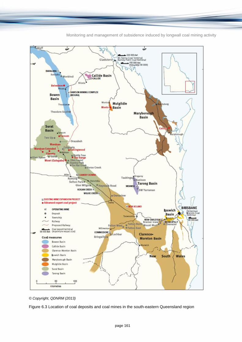
Monitoring and management of subsidence induced by longwall coal mining activity
page 161
© Copyright, QDNRM (2013)
Figure 6.3 Location of coal deposits and coal mines in the south-eastern Queensland region

Monitoring and management of subsidence induced by longwall coal mining activity
page 162
Figure 6.4 Location of longwall coal mines in the Bowen and Galilee Basins
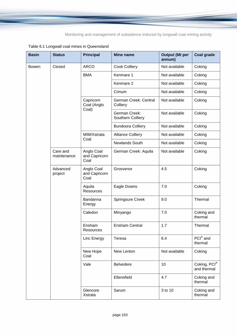
Monitoring and management of subsidence induced by longwall coal mining activity
page 163
Table 6.1 Longwall coal mines in Queensland
Basin Status Principal Mine name Output (Mt per annum)
Coal grade
Bowen Closed ARCO Cook Colliery Not available Coking
BMA Kenmare 1 Not available Coking
Kenmare 2 Not available Coking
Crinum Not available Coking
Capricorn Coal (Anglo Coal)
German Creek: Central Colliery
Not available Coking
German Creek: Southern Colliery
Not available Coking
Bundoora Colliery Not available Coking
MIM/Xstrata Coal
Alliance Colliery Not available Coking
Newlands South Not available Coking
Care and maintenance
Anglo Coal and Capricorn Coal
German Creek: Aquila Not available Coking
Advanced project
Anglo Coal and Capricorn Coal
Grosvenor 4.5 Coking
Aquila Resources
Eagle Downs 7.0 Coking
Bandanna Energy
Springsure Creek 9.0 Thermal
Caledon Minyango 7.0 Coking and thermal
Ensham Resources
Ensham Central 1.7 Thermal
Linc Energy Teresa 6.4 PCIA and
thermal
New Hope Coal
New Lenton Not available Coking
Vale Belvedere 10 Coking, PCIA
and thermal
Ellensfield 4.7 Coking and thermal
Glencore Xstrata
Sarum 3 to 10 Coking and thermal

Monitoring and management of subsidence induced by longwall coal mining activity
page 164
Basin Status Principal Mine name Output (Mt per annum)
Coal grade
Operating Anglo Coal German Creek: Grasstree
4.5 Coking
Moranbah North 4.5 Coking
BMA Broadmeadow 4.8 Coking
Crinum North 4.25 Coking
Peabody Energy
North Goonyella 3.0 Coking
Rio Tinto Coal Kestrel 4.2 Coking
Vale Carborough Downs 3.5 Coking, PCIA
and thermal
Glencore Xstrata
Newlands: Northern Colliery
1.5 Coking, PCIA
and thermal
Oaky Creek No. 1 5.5 Coking
Oaky North 5.5 Coking
Galilee Advanced project
Alpha Coal Management
South Galilee 15 Thermal
GVK Resources and Hancock Coal
Alpha 30 Thermal
GVK Resources
Kevin's Corner 30 Thermal
Waratah Coal Galilee Coal Project 40 Thermal
Adani Carmichael Coal Mine 60 Thermal
Macmines Austasia
China Stone 35 Thermal
Source: compiled from QDNRM (2012a) and J Grieves 2012, pers. comm.8
Notes: A PCI: pulverised coal injection specification thermal coal.
8 Grieves, J. (Alternate Director) for Australian Coal Research Limited.

Monitoring and management of subsidence induced by longwall coal mining activity
page 165
6.2 Description of the Bowen Basin
6.2.1 Stratigraphy and hydrostratigraphy
The Bowen Basin formed above a basement of early Palaeozoic metamorphic and sedimentary rocks of the Drummond Basin and Anakie Block. The development of the basin initiated with rifting in the early Permian resulting in a series of isolated fault-bounded basins filled with volcanics and sediments (Esterle & Sliwa 2002). Thermal relaxation took over as the mechanism for subsidence when rifting ceased by the middle Permian, and marine conditions dominated the basin until the late Permian (e.g. Back Creek Group, Tiverton Formation; Esterle & Sliwa 2002). During the late Permian to middle Triassic period, the basin filled with a thick sequence of sediments including coal measures (e.g. Moranbah-German Creek Coal Measures and Rangal Coal Measures; Esterle & Sliwa 2002). Triassic sediments outcropping and subcropping in the southern part of the basin have largely been eroded from the northern Bowen Basin leaving only a few isolated outcrops.
A generalised stratigraphic sequence for the Bowen Basin is shown in Table 6.2.
Table 6.2 Generalised stratigraphy for the Bowen Basin
Geological age
Stratigraphic unit
Lithological description Thickness Depositional environment
Quaternary Recent alluvial deposits
Sand, silt, gravel, clay 0 to 90 m Alluvial
Tertiary Tertiary alluvium Silts, clay, sand and gravel Up to 100 m Alluvial and fluvial
Fresh and weathered basalt
Olivine basalt flows, rare basalt plugs and sills, and overlying sediments
0 to 250 m Volcanic
Triassic
Moolayember Formation
Mudstones, siltstones, sandstones, carbonaceous shale, coal, conglomerate and minor tuff and limestone
0 to 1500 m Dominantly fluvial-lacustrine environment, although includes deltaic and shallow marine transition environments
Clematis Group Quartzose sandstone, siltstone and mudstone
0 to 2000 m Fluvial (braided and meandering) and floodplain
Rewan Formation Mudstone, siltstone and labile sandstone
0 to 3600A m Alluvial and
lacustrine
Mid to late Permian
Northern coal seams:
Moranbah Coal Measures, Fort Cooper Coal Measures and Rangal Coal Measures.
Shale, siltstone, mudstone, tuff, coal, sandstone
0 to 600 m (for individual coal measures)
Coal deposits accumulated in swamp environments on an extensive coastal plain and alluvial plain

Monitoring and management of subsidence induced by longwall coal mining activity
page 166
Geological age
Stratigraphic unit
Lithological description Thickness Depositional environment
Southern coal seams:
Bandanna Formation Baralaba Coal Measures
Early Permian
Back Creek Group
Siltstone, carbonaceous shale, mudstone, clayey sandstone
0 to >1200 m Marine shelf deposits during period of slow basin subsidence
Source: modified from CSIRO, NCGRT and SKM (2012) unless stated otherwise; AOlgers (1966);
BGreen et al.
(1997).
6.2.2 Coal resources
Economic coal reserves are contained in the Permian sedimentary sequence. In the north of the basin, coal seams are found in the Moranbah Coal Measures, Fort Cooper Coal Measures (equivalent to Burngrove Formation and Fairhill Formation combined, occurring in the central basin) and Rangal Coal Measures. In the south of the basin, coal seams are found in the Bandanna Formation and the Baralaba Coal Measures.
Esterle and Sliwa (2002) developed a model (Supermodel 2000; Figure 6.5) of the Moranbah-German Creek Coal Measures along the western limb of the Bowen Basin from integrated mine-scale databases and regional basement geology. The model extent ranges from approximately 75 km north of Moranbah to 25 km north of Emerald and includes the Wards Well, Grosvenor, Peak Downs, Norwich Park, German Creek and Kestrel mines (refer Figure 6.1). Supermodel 2000 was developed from mine site drilling (37 250 drill holes), open cut and underground mapping of faults, joints and coal cleats, available geophysics (seismic, aeromagnetics, and gravity) and stress measurements. Where available, the sedimentary character of the interburden was also included to allow a complete description of ground conditions. The model was current as at December 2000 (Esterle & Sliwa 2002) and is an excellent baseline reference for the development of geotechnical conceptual and numerical models for any greenfield and brownfield sites in the Bowen Basin.
Coal seams in the northern section of the Bowen Basin have a cumulative thickness of 20 to 30 m and progressively thin towards the south. The coal seams are separated by siltstones, mudstones, tuffaceous strata and sandstone units, which vary in thickness from less than 1 m to more than 60 m. The coal seams vary from three to 11 m thick and locally split and coalesce. The most persistent superseams in stratigraphic order from oldest to youngest are (Esterle & Sliwa 2002):
Lower superseam (Goonyella Lower – Dysart – German Creek seams) up to 12 m thick
Middle superseam (Goonyella Middle – Harrow Creek – Aquila seams) up to 12 m thick
‘P-tuff’ regional tuffaceous unit (locally coupled with the P-superseam)
P-superseam (P seams – Pleiades seam) up to 5 m thick
Upper superseam (Goonyella upper seams) up to 6 m thick.
The four superseams are shown in a long section in Figure 6.5.

Monitoring and management of subsidence induced by longwall coal mining activity
page 167
© Copyright, Esterle and Sliwa (2002)
Figure 6.5 Regional correlation sections through Supermodel 2000 tiles showing general thickness and splitting patterns of the major superseams over a section length of 200 km from 75 km north of Moranbah to 25 km north of Emerald, Qld
6.2.3 Groundwater in the Bowen Basin
6.2.3.1 Groundwater occurrence and use
The generalised hydrostratigraphy for the Bowen Basin is shown in Table 6.3 including a summary of groundwater quality, bore yield, use and management. Registered bores with at least one water level record were reviewed by URS (2012b) for the northern Bowen Basin. Table 6.3 gives an indication of groundwater use and allocation associated with each of the hydrostratigraphic units.
A previous review indicated that groundwater resources north of Blackwater are limited (URS 2012b). The main regional aquifer with a high beneficial use potential based on quality and yield criteria is the Jurassic Clematis Group of the GAB; however yields are highly variable (Table 6.3). The Clematis Sandstone has mostly been eroded from the northern Bowen Basin leaving remnants that appear disconnected (URS 2012b). Minor water-bearing units are also found in the coal measures, the surficial Tertiary basalts and Tertiary and Quaternary alluvials, but yields and quality vary significantly. Records of registered groundwater bores suggest that Quaternary alluvial aquifers that occur in discontinuous lenses along major streams and rivers form the main groundwater resource across much of the basin. Tertiary basalt aquifers are also locally important groundwater resources that occur mostly along the northwest and eastern fringes, although groundwater is typically of poor quality (URS 2012b). More recent work suggests that groundwaters from the Tertiary basalts in the Rolleston, Minerva and Springsure Creek areas generally have ECs less than 1500 µS per cm (QDNRM 2014a).
Coal seams can be the most permeable aquifers in some areas and can supply stock and domestic bores (QDNRM 2012d). However, many of these bores produce low to moderate yields of brackish water which is considered unsuitable for agricultural or domestic use (URS 2012b).
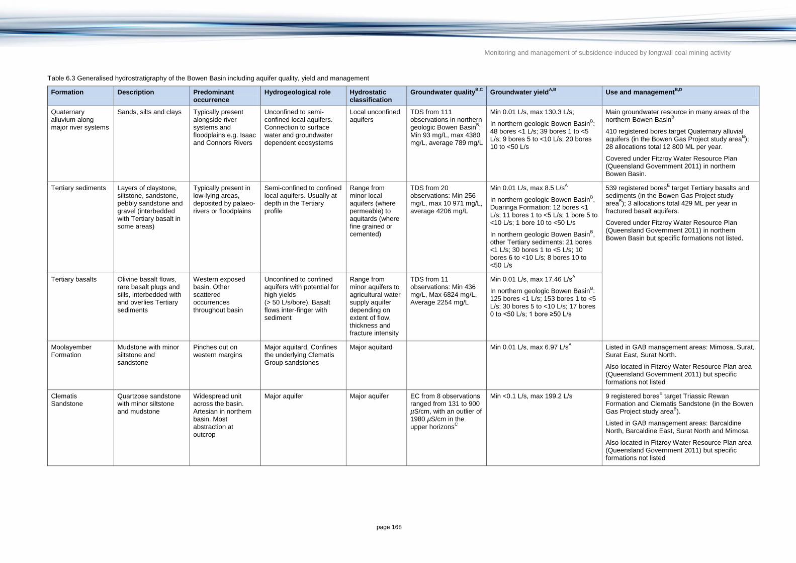
Monitoring and management of subsidence induced by longwall coal mining activity
page 168
Table 6.3 Generalised hydrostratigraphy of the Bowen Basin including aquifer quality, yield and management
Formation Description Predominant occurrence
Hydrogeological role Hydrostatic classification
Groundwater qualityB,C
Groundwater yieldA,B
Use and managementB,D
Quaternary alluvium along major river systems
Sands, silts and clays Typically present alongside river systems and floodplains e.g. Isaac and Connors Rivers
Unconfined to semi-confined local aquifers. Connection to surface water and groundwater dependent ecosystems
Local unconfined aquifers
TDS from 111 observations in northern geologic Bowen Basin
B:
Min 93 mg/L, max 4380 mg/L, average 789 mg/L
Min 0.01 L/s, max 130.3 L/s;
In northern geologic Bowen BasinB:
48 bores <1 L/s; 39 bores 1 to <5 L/s; 9 bores 5 to <10 L/s; 20 bores 10 to <50 L/s
Main groundwater resource in many areas of the northern Bowen Basin
B
410 registered bores target Quaternary alluvial aquifers (in the Bowen Gas Project study area
B);
28 allocations total 12 800 ML per year.
Covered under Fitzroy Water Resource Plan (Queensland Government 2011) in northern Bowen Basin.
Tertiary sediments Layers of claystone, siltstone, sandstone, pebbly sandstone and gravel (interbedded with Tertiary basalt in some areas)
Typically present in low-lying areas, deposited by palaeo-rivers or floodplains
Semi-confined to confined local aquifers. Usually at depth in the Tertiary profile
Range from minor local aquifers (where permeable) to aquitards (where fine grained or cemented)
TDS from 20 observations: Min 256 mg/L, max 10 971 mg/L, average 4206 mg/L
Min 0.01 L/s, max 8.5 L/sA
In northern geologic Bowen BasinB,
Duaringa Formation: 12 bores <1 L/s; 11 bores 1 to <5 L/s; 1 bore 5 to <10 L/s; 1 bore 10 to <50 L/s
In northern geologic Bowen BasinB,
other Tertiary sediments: 21 bores <1 L/s; 30 bores 1 to <5 L/s; 10 bores 6 to <10 L/s; 8 bores 10 to <50 L/s
539 registered boresE target Tertiary basalts and
sediments (in the Bowen Gas Project study area
B); 3 allocations total 429 ML per year in
fractured basalt aquifers.
Covered under Fitzroy Water Resource Plan (Queensland Government 2011) in northern Bowen Basin but specific formations not listed.
Tertiary basalts Olivine basalt flows, rare basalt plugs and sills, interbedded with and overlies Tertiary sediments
Western exposed basin. Other scattered occurrences throughout basin
Unconfined to confined aquifers with potential for high yields (> 50 L/s/bore). Basalt flows inter-finger with sediment
Range from minor aquifers to agricultural water supply aquifer depending on extent of flow, thickness and fracture intensity
TDS from 11 observations: Min 436 mg/L, Max 6824 mg/L, Average 2254 mg/L
Min 0.01 L/s, max 17.46 L/sA
In northern geologic Bowen BasinB:
125 bores <1 L/s; 153 bores 1 to <5 L/s; 30 bores 5 to <10 L/s; 17 bores 0 to <50 L/s; 1 bore ≥50 L/s
Moolayember Formation
Mudstone with minor siltstone and sandstone
Pinches out on western margins
Major aquitard. Confines the underlying Clematis Group sandstones
Major aquitard Min 0.01 L/s, max 6.97 L/sA
Listed in GAB management areas: Mimosa, Surat, Surat East, Surat North.
Also located in Fitzroy Water Resource Plan area (Queensland Government 2011) but specific formations not listed
Clematis Sandstone
Quartzose sandstone with minor siltstone and mudstone
Widespread unit across the basin. Artesian in northern basin. Most abstraction at outcrop
Major aquifer Major aquifer EC from 8 observations ranged from 131 to 900 µS/cm, with an outlier of 1980 µS/cm in the upper horizons
C
Min <0.1 L/s, max 199.2 L/s
9 registered boresE target Triassic Rewan
Formation and Clematis Sandstone (in the Bowen Gas Project study area
B).
Listed in GAB management areas: Barcaldine North, Barcaldine East, Surat North and Mimosa
Also located in Fitzroy Water Resource Plan area (Queensland Government 2011) but specific formations not listed

Monitoring and management of subsidence induced by longwall coal mining activity
page 169
Formation Description Predominant occurrence
Hydrogeological role Hydrostatic classification
Groundwater qualityB,C
Groundwater yieldA,B
Use and managementB,D
Rewan Formation Interbedded sandstone (high proportion of clay and silt), mudstone and siltstone
Widespread unit across the basin
Basal confining layer of the GAB
Major aquitard Generally considered to be poor with elevated EC in the order of 25 000 µS/cm
C
Min <1 L/s, max 30.1 L/sA
9 registered boresE target Triassic Rewan
Formation and Clematis Sandstone (in the Bowen Gas Project study area
B)
Listed in GAB management area: Mimosa.
Also located in Fitzroy Water Resource Plan area (Queensland Government 2011) but specific formations not listed
Permian Coal Measures
Interbedded coal and sandstone, siltstone and mudstone
Extensive coal measures across the basin
Target coal seams for both coal mining and CSG abstraction
Poor to moderate permeability aquifer (Water-bearing units
1
within aquitard interbeds)
TDS from 57 observations: Min 400 mg/L, max 13 835 mg/L, average 3456 mg/L
Min 0.6 L/s, max 135 L/sA
169 registered boresE target Permian Coal
Measures (in the Bowen Gas Project study areaB);
7 allocations total 3870 ML per year in Blackwater Group.
Located in Fitzroy Water Resource Plan area (Queensland Government 2011) but specific formations not listed
Deep reservoirs Interbedded coal and sandstone
Present at significant depths
Limited data available on groundwater conditions in deeper Permian sediments
Poor to moderate permeability aquifer (water-bearing units
A
within aquitard interbeds)
TDS from 6 observations in small portion Bowen Gas Project study area
B: Min
457 mg/L, max 28 480 mg/L, average 3823 mg/L
<0.01 L/s to 22.5 L/sA (Back Creek
Group) 1 allocation of 40 ML per year in Back Creek Group.
Located in Fitzroy Water Resource Plan area (Queensland Government 2011) but specific formations not listed
Source: modified from CSIRO, NCGRT and SKM (2012) unless stated otherwise.
A QDNRM (2012d) range based on bore yields reported in and around selected Authority to Prospect areas (684, 685, 693, 722, 756, 768, 769, 806, 811) across the central and north of the basin.
B URS (2012b) (Bowen Gas Project study area covers significant portion of Bowen Basin around and north of Blackwater, the project area is a sub-area of the study area).
C Worley Parsons (2013) and citations within.
D Queensland Government (2006, 2011).
E Registered bores with at least one water level data record.
Monitoring and management of subsidence induced by longwall coal mining activity
page 170
6.2.3.2 Groundwater management
Groundwater resource management in Queensland differs depending on the location and type of groundwater and is classified as sub-artesian or artesian water (QDNRM 2012d). Both a water licence and a development permit are required to take or interfere with artesian water anywhere in the state under the Queensland Water Act 2000 and the Sustainable Planning Act 2009 (QDNRM 2012d).
Groundwater in the northern Bowen Basin is managed under the Water Resource (Fitzroy Basin) Plan 2011 (Queensland Government 2011). The southern section of the Bowen Basin lies in the GAB where artesian water and sub-artesian water connected to artesian water are managed under the Water Resource (Great Artesian Basin) Plan 2006 and the Great Artesian Basin Resource Operations Plan (QDNRM 2012e) and the Fitzroy Basin Plan (Queensland Government 2011). Water resource plans define the availability and allocation of water in the plan area. Water resource plans identify groundwater management areas (GMAs) and associated groundwater management units (GMU), or sub-areas with specified upper limits to annual allocation of groundwater.
North of the town of Glenden there are no GMAs or sub-artesian areas under which groundwater is managed (QDNRM 2014a). There is also an area including Moura and Baralaba where no GMAs or sub-artesian areas currently apply (QDNRM 2014a).
The Water Resource (Great Artesian Basin) Plan 2012 identifies 25 GMAs in the GAB; associated GMUs correspond to artesian water, sub-artesian water connected to artesian water, and water in springs associated with the Moolayember Formation, the Clematis Sandstone and the Rewan Formation (QDNRM 2012e). The Bowen Basin covers four of these GMAs (Barcaldine North, Barcaldine East, Surat North and Mimosa) (QDNRM 2012e). This area is overlapped by the Carnarvon GMA of the Fitzroy WRP, under which all other groundwater is managed (QDNRM 2014a). With the exception of domestic purposes, all groundwater extraction from the GAB is licensed including for stock watering.
6.2.3.3 Groundwater flow
The limited spatial and temporal groundwater monitoring data across the Bowen Basin makes interpretations of regional groundwater flow patterns difficult. The main recharge processes occurring in the northern Bowen Basin include diffuse and localised recharge of surficial aquifers (including the Quaternary alluvial and outcropping Tertiary sediments and basalt aquifers) that is rapid and responsive to rainfall, and diffuse recharge of confined aquifers that is slower and generally unresponsive to rainfall (QWC 2012; URS 2012b).
Localised recharge to alluvial aquifers via rainfall recharge and from stream leakage is supported by documented linkages between rainfall, stream flow and watertable levels (QWC 2012; URS 2012b and citations within). Shallow groundwater flow is generally towards drainage lines which act as discharge points. Groundwater in surficial aquifers is also discharged via evapotranspiration, interflow, or vertical seepage into deeper units (URS 2012b). In the central and northern Bowen Basin, vertical leakage to and between underlying Triassic and Permian units from unconfined aquifers is expected to be negligible due to the low permeability and confining nature of the Moolayember and Rewan Formations. Recharge to the Clematis Sandstone Aquifer and water bearing units in the Permian strata is considered to occur where the major aquitards are absent and the aquifers outcrop or subcrop beneath surficial sediments. Of particular relevance to this report are the isolated occurrences of the Clematis Sandstone Aquifer in the northern part of the basin where longwall coal mines are located (Figure 6.4). These isolated occurrences are outside the GAB and are not
Monitoring and management of subsidence induced by longwall coal mining activity
page 171
hydraulically connected to the main occurrences of GAB Jurassic sediments to the south and west.
Groundwater is expected to flow from outcropping recharge zones along the direction of dip. However, connectivity between the coal measures of the Blackwater Group and the overlying alluvial and Tertiary basalt aquifers in the northern Bowen Basin is poorly understood, and that between the Moolayember Formation, Rewan Formation and Clematis Group sandstones is unknown (CSIRO, NCGRT & SKM 2012).
In the north and along the eastern margins of the basin where folding and subsequent erosion, uplift and faulting has occurred, there may be hydraulic connection between units. Sub-vertical fault zones and fractures may provide preferential flow paths through low permeability layers to underlying aquifers if these faults are sufficiently permeable (URS 2012b).
6.2.3.4 Groundwater and surface water interaction
Several reaches of the Connors and Isaac Rivers in the central Bowen Basin have been identified as baseflow reaches, variably gaining from and losing to the underlying groundwater system (SKM 2009a, 2009b; Bureau of Meteorology 2013). Riverine wetlands associated with the upper reaches of the Mackenzie River catchment have also been identified in desktop studies as being partially reliant on groundwater (Bureau of Meteorology 2013).
Many of the upper reaches and tributaries of the Isaac River catchment are ephemeral or episodic in nature (SKM 2009a, 2009b) and not connected to the groundwater system. However, during heavy rainfall periods and hence periods of recharge to alluvial aquifers, groundwater may help maintain flow or help maintain inundation of some reaches and floodplain wetlands or billabongs.
More information on springs, wetlands and rivers in the Bowen Basin can be found in Section 6.2.5.2.
6.2.3.5 Potential impacts on groundwater resources
All longwall mining developments in the Bowen Basin (historic, current and planned) are well outside the GAB boundary (Figure 6.4). Impacts of longwall coal mine subsidence on GAB units (including the Clematis Sandstone Aquifer) are therefore not considered to be likely.
Isolated outcrops of Clematis Sandstones outside the GAB could potentially be affected by longwall coal mining such as in and around the Karborough Range and Kerlong Range north of Coppabella (e.g. near the Ellensfield Mine). The isolated occurrences of Clematis Sandstone Aquifer are not currently used for water supply to any great extent and are hydraulically separated from the GAB units to the west by significant thicknesses of Permian units. Any impact on isolated units is not likely to affect the GAB or its recharge areas to the west.
The impact of longwall coal mine subsidence on Tertiary basalt and Quaternary alluvial aquifers is dependent on the natural vertical hydraulic connection between the coal measures and these surficial deposits and the changes in vertical connection resulting from subsidence (Section 2.3). In most cases significant thicknesses of Rewan Formation hydraulically separate coal measures from overlying units. The effectiveness of this seal has not been field-validated and structural features may enhance preferential flow paths through the Rewan Formation.
Significant heterogeneity has been noted in each of the major Bowen Basin hydrostratigraphic units and there are countless facies changes, complex basin-wide erosion events that removed large sections of sedimentary profiles, and other zones that have been altered post-
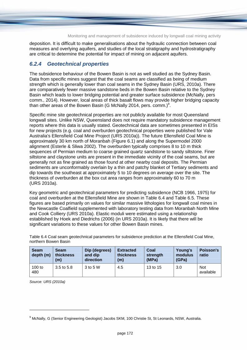
Monitoring and management of subsidence induced by longwall coal mining activity
page 172
deposition. It is difficult to make generalisations about the hydraulic connection between coal measures and overlying aquifers, and studies of the local stratigraphy and hydrostratigraphy are critical to determine the potential for impact of mining on adjacent aquifers.
6.2.4 Geotechnical properties
The subsidence behaviour of the Bowen Basin is not as well studied as the Sydney Basin. Data from specific mines suggest that the coal seams are classified as being of medium strength which is generally lower than coal seams in the Sydney Basin (URS, 2010a). There are comparatively fewer massive sandstone beds in the Bowen Basin relative to the Sydney Basin which leads to lower bridging potential and greater surface subsidence (McNally, pers comm., 2014). However, local areas of thick basalt flows may provide higher bridging capacity than other areas of the Bowen Basin (G McNally 2014, pers. comm.)9.
Specific mine site geotechnical properties are not publicly available for most Queensland longwall sites. Unlike NSW, Queensland does not require mandatory subsidence management reports where this data is usually stated. Geotechnical data are sometimes presented in EISs for new projects (e.g. coal and overburden geotechnical properties were published for Vale Australia's Ellensfield Coal Mine Project (URS 2010a)). The future Ellensfield Coal Mine is approximately 30 km north of Moranbah (Figure 6.1) and along the Supermodel 2000 alignment (Esterle & Sliwa 2002). The overburden typically comprises 8 to 10 m thick sequences of Permian medium to coarse grained quartz sandstone to sandy siltstone. Finer siltstone and claystone units are present in the immediate vicinity of the coal seams, but are generally not as fine grained as those found at other nearby coal deposits. The Permian sediments are unconformably overlain by a thin and patchy blanket of Tertiary sediments and dip towards the southeast at approximately 5 to 10 degrees on average over the site. The thickness of overburden at the box cut area ranges from approximately 60 to 70 m (URS 2010a).
Key geometric and geotechnical parameters for predicting subsidence (NCB 1966, 1975) for coal and overburden at the Ellensfield Mine are shown in Table 6.4 and Table 6.5. These figures are based primarily on values for similar massive lithologies for longwall coal mines in the Newcastle Coalfield supplemented with laboratory testing data from Moranbah North Mine and Cook Colliery (URS 2010a). Elastic moduli were estimated using a relationship established by Hoek and Diedrichs (2006) (in URS 2010a). It is likely that there will be significant variations to these values for other Bowen Basin mines.
Table 6.4 Coal seam geotechnical parameters for subsidence prediction at the Ellensfield Coal Mine, northern Bowen Basin
Seam depth (m)
Seam thickness (m)
Dip (degrees) and dip direction
Extracted thickness (m)
Coal strength (MPa)
Young's modulus (GPa)
Poisson's ratio
100 to 480
3.5 to 5.8 3 to 5 W 4.5 13 to 15 3.0 Not available
Source: URS (2010a)
9 McNally, G (Senior Engineering Geologist) Jacobs SKM, 100 Christie St, St Leonards, NSW, Australia.

Monitoring and management of subsidence induced by longwall coal mining activity
page 173
Table 6.5 Overburden geotechnical parameters for subsidence prediction at the Ellensfield Coal Mine, northern Bowen Basin
Overburden type Subsidence reducing unit and thickness (m)
Rockmass strength (MPa)
Young's modulus (GPa)
Poisson's ratio
Predominantly mudstone and sandstone (80:20)
Major unit 15 thick sandstone 100 above seam
2.2 to 92
average 31
1.8 to 61
average 12.3
0.1 to 0.45
average 0.3
Source: URS (2010a)
URS (2010a) reported that the first 6 m below the proposed extracted coal seam at the Ellensfield Mine comprises interbedded siltstone and sandstone which has an unconfined compressive strength range between six and 75 MPa. The coal classifies as a medium strength rock and the overburden and floor is generally medium to high strength rock according to AS 1726 Geotechnical site investigations (Standards Australia 1993). A 15 m thick sandstone unit in the overburden at Ellensfield Mine was assessed by Ditton Geotechnical Services to provide a low to moderate subsidence reducing potential (URS 2010a).
The stronger the rock mass, the lower the level of subsidence at the surface, although the difference is not great (e.g. 50 to 55 per cent of extracted seam height in strong rock compared to 60 to 65 per cent in weaker strata). The conceptual parameters in Table 6.5 suggest that the Ellensfield Mine overburden is highly variable, but in general somewhat weaker than NSW Southern Coalfield rocks.
Two-dimensional subsidence profiles were created for the Ellensfield mine using empirical methods and extrapolated to encompass the mine area in three dimensions (URS 2010a). It was predicted that maximum subsidence would be 2.93 m for a 4.5 m extracted thickness. These figures have not been verified because the Ellensfield Mine has yet to be developed.
6.2.5 Surface water in the Bowen Basin
Table 6.6 shows surface water related information sources considered in the Bowen Basin. Appendix B lists the key surface water features located in each coal basin. Surface water resources identified in this section include locations which are outside of the coal basins but which may be affected by changes to downstream flows.
Figure 6.6 and Figure 6.7 show the main surface water features relative to coal resources in the northern and southern Bowen Basin, respectively. The following sections provide a summary of the GDEs, nationally significant wetlands, and surface water resources used for water supply relevant to longwall coal mining in the Bowen Basin.

Monitoring and management of subsidence induced by longwall coal mining activity
page 174
Table 6.6 Information used to characterise surface water resources
Property Source Comment
Coal measures
Queensland Department of Employment, Economic Development and Innovation (QDEEDI 2012)
A number of spatial layers identify the extent of coal basins, some of which differ in boundary extents. Mapping of resources may change as knowledge improves. QDEEDI (2012) contained the most up to date information at the time of writing.
Major watercourses
Queensland Department of Natural Resources and Mines (QDNRM 2012b)
Information on major watercourses, surface water use and ecosystem reliance.
GDEs
Bureau of Meteorology, (Bureau of Meteorology 2013)
The National Atlas of groundwater dependent ecosystems provides three classifications of GDEs:
reliant on surface expression of groundwater (rivers, springs, wetlands)
reliant on subsurface groundwater (vegetation)
subterranean (caves and aquifers).
GDEs are classified as either previously identified (through fieldwork or desktop studies) or inferred through a combination of broad scale analysis, existing datasets and remote sensing methods.
Dams and weirs
Queensland Department of Natural Resources and Mines (QDNRM 2012c)
Information on key dams and weirs but may not identify all structures, particularly smaller ones.
Significant wetlands
Queensland Department of Environment and Heritage Protection (QEHP 2005)
Information on the wetlands cited in ‘A directory of important wetlands in Australia’ third edition (Environment Australia 2001), and various additions for wetlands listed after 2001.
6.2.5.1 Surface water occurrence and use
Coal measures in the Bowen Basin underlie the Fitzroy Basin and the Burdekin Catchment (Figure 6.6 and Figure 6.7). Major watercourses are the Nogoa, Isaac, Connors, Dawson and Comet Rivers, which have extensive areas of alluvial river beds (GSQ 2012) and are either ephemeral or display a strongly seasonal flow regime (Lucas et al. 2009). Smaller watercourses are generally ephemeral.
While headwater catchments may be steep, the majority of the catchments are relatively flat with gently rolling hills and extensive plains. Rivers in these basins are generally low gradient, incised watercourses. Terraces and instream benches are often present within river channels, with abandoned channels and anabranches also commonly observed (SunWater 2012). Overbank flooding is common, with extensive floodplains along watercourses (SunWater 2012).
The majority of the highly seasonal flow occurs between December and April (SunWater 2012). High flow events generally occur in late summer and early autumn and may cause extensive flooding (SunWater 2012). Floodwaters often remain in place for extended periods. While some watercourses in the Bowen Basin are observed to have intermittent or minimal bedrock present they may still contain bedrock controls (Lucas et al. 2009). For example, the Dawson River meanders over both alluvial and sedimentary rock landscapes, with rock bars forming
Monitoring and management of subsidence induced by longwall coal mining activity
page 175
waterholes along the river (SunWater 2012). Sections of the Isaac River have minimal bedrock while Goonyella Creek and Connors River have bedrock in places.
The majority of the Bowen Basin is highly developed in terms of surface water use. Major uses include town water supply, industrial use, agricultural use, and stock and domestic use. There are a large number of water storages across the basin (major storages are listed in Appendix B). Most of the major storages are in the southern Bowen Basin (Figure 6.7) along the Nogoa-Mackenzie and Dawson Rivers. The largest storage is Fairbairn Dam (1301 GL; QDNRM 2013) in the Nogoa-Mackenzie Water Supply Scheme, which supplies approximately 235 300 ML per year for town water supply, industrial, mining and agricultural purposes (QDNRM 2013). Six smaller storages are located along the Dawson River (Glebe Weir, Gyranda Weir, Orange Creek Weir, Theodore Weir, Moura Weir and Neville Hewitt Weir) which supply approximately 61.8 GL per year for town water supply, industrial, mining and agricultural purposes (QDNRM 2013).
There is also a significant amount of unsupplemented (unregulated) water use in these areas, particularly for agricultural and stock and domestic purposes (QDNRM 2013).

Monitoring and management of subsidence induced by longwall coal mining activity
page 176
Figure 6.6 Significant wetlands and GDEs in the northern Bowen Basin

Monitoring and management of subsidence induced by longwall coal mining activity
page 177
Figure 6.7 Significant wetlands and GDEs in the southern Bowen Basin

Monitoring and management of subsidence induced by longwall coal mining activity
page 178
6.2.5.2 GDEs
GDEs are partially or completely dependent on groundwater for their existence or health. The National Atlas of GDEs (GDE Atlas; Bureau of Meteorology 2013) was used to identify GDEs in the coal basins. Inferred GDEs are rated in the GDE Atlas (Bureau of Meteorology 2013) as having low, moderate or high potential for groundwater interaction (i.e. a low, moderate or high likelihood that they are actually GDEs).
Table 6.7 shows the number of known and inferred GDEs identified in the GDE Atlas for the Bowen Basin. Figure 6.6 and Figure 6.7 show the known and inferred GDEs spatially, along with the location of current and potential future coal mine sites.
Table 6.7 Estimated number of GDEs in the Bowen Basin
Area (km2)
Known GDEs
Inferred GDEs: Potential for groundwater interaction
High Moderate Low
34 330 22 1104 3515 791
Source: QDEEDI (2012) and Bureau of Meteorology (2013)
Table 6.7 indicates that the presence of GDEs is generally unconfirmed, as the majority of GDEs have been inferred through spatial analysis.
The majority of known GDEs are located in the headwaters of Meteor Creek, Blackwater Creek, Charlevue Creek, Moolayember Creek, Spring Creek and the Dawson River in the south of the basin (Figure 6.7). There are extensive areas along the major watercourses which have a moderate potential for GDE presence. Significant lakes include Lake Nuga Nuga and Fairbairn Dam which are both listed in the directory of important wetlands in Australia (DIWA; Environment Australia 2001). Fairbairn Dam is also an important water storage which supplies irrigators in the region. A number of smaller water supply storages in the southern Bowen Basin supply water for agricultural, industrial and urban demands.
In the north of the basin (Figure 6.6) there are extensive areas along the major watercourses which have a moderate to high potential for GDE presence. A number of lakes and wetlands are present, including Lake Elphinstone and Birralee-Pelican Creek which are both listed in the DIWA (Environment Australia 2001).
Many of the springs in the Bowen Basin are thought to be associated with faults, surface depressions (e.g. creek lines), or discharge through thinning confining beds (QWC 2012). Information on spring discharge processes and source aquifers is generally lacking. The recovery plan for the GAB springs, including some identified in the Bowen Basin, acknowledges that while the connectivity of groundwater sources to spring vents is understood in general terms, detailed hydrology at individual spring locations is poorly understood and in some places the source aquifer to the spring is not known (Fensham et al. 2010).
6.2.5.3 Significant wetlands
For the purpose of this report, significant wetlands are considered to be Ramsar listed wetlands (Ramsar Convention 1999) and those which are listed in the DIWA (Environment Australia 2001). The following criteria were given by the Department of the Environment and Water Resources for inclusion in the directory (DEW 2006) and are broadly based on the Ramsar definition for internationally significant wetlands:

Monitoring and management of subsidence induced by longwall coal mining activity
page 179
‘To be considered nationally important, a wetland must meet at least one of the six nationally agreed criteria. The criteria cover the following areas: biogeographic representativeness; important ecological or hydrological functions; provision of animal habitat during times of vulnerability or adverse conditions; support for more than one per cent of the national population of any taxa; support for threatened taxa or communities; and historical or cultural significance.’
Figure 6.8 shows different types of wetland systems present in Queensland (QEHP 2013). All of these wetland systems may also be groundwater dependent and as such there are a number of water assets which may cross over different categories.
© Copyright, QEHP (2013)
Figure 6.8 Schematic depiction of wetland systems present in Queensland
Appendix B summarises DIWA and Ramsar listed wetlands in each of coal basin. Although there are no Ramsar wetlands in the Bowen Basin, there are a number of DIWA wetlands as shown in Figure 6.6 and Figure 6.7.
There are five DIWA wetlands in the Bowen Basin: Boggomoss Springs, Fairbairn Dam, Lake Elphinstone, Lake Nuga Nuga and Birralee-Pelican Creek (Figure 6.6 and Figure 6.7). Three DIWA wetlands outside the Bowen Basin could also potentially be affected by upstream mining activities (Burdekin-Bowen Junction and Blue Valley Weir Aggregation, Lake Dalrymple, Scartwater Aggregation), although this is considered a very low risk due to their distance from the basin.
6.2.5.4 Potential impacts on surface water resources
Predicting the degree of subsidence and the resulting impact to surface water resources at a regional scale is difficult (Section 3.3). The level of subsidence is highly dependent on site specific factors, such as mine design, seam thickness, pillar width, depth of overburden, geology and local topography (NSW Scientific Committee 2005), and possible impacts to surface water resources are also dependent on their proximity to areas of subsidence.
The NSW Scientific Committee noted that ‘mining subsidence is frequently associated with cracking of valley floors and with subsequent effects on surface and groundwater hydrology’ (NSW Scientific Committee 2005). There are two general vectors through which surface water resources are affected by subsidence; first through the alteration of surface water flow paths, and second through loss of surface water to groundwater (Parsons Brinckerhoff 2007). This can dry out existing watercourses and disconnect flow paths with wetlands, lakes and swamps.
Subsidence impacts are predicted to be higher in hilly terrains than in flatter areas (Elsworth & Liu 1995; Holla 1997; Holla & Barclay 2000; Waddington & Kay 2002). Waddington and Kay

Monitoring and management of subsidence induced by longwall coal mining activity
page 180
(2002b) observed that as the depth of the watercourse incision increases, the degree of valley closure and upsidence increases. Additionally, as the depth and width of watercourse incision increases the width of influence on the subsidence profiles also increases.
The alluvial rivers commonly found in the Bowen Basin are more likely to be affected by subsidence induced lowering of channel beds and changes in grade than by bedrock cracking. The extent to which subsidence affects the stability of the channel and broader drainage network will depend on the degree to which subsidence alters channel hydraulics and patterns of sediment erosion, transport and storage. Geomorphic instabilities can be propagated upstream and downstream from the initial site of disturbance as a result of the fluvial system responding to changes in bed levels.
While the relatively flat gradients of the watercourses in the Bowen Basin may reduce the likelihood of transportation of solids such as sediment and rock (which act to keep cracks beneath watercourses open), it is also possible that the thick alluvial deposits in many of these watercourses may act to prolong dewatering if cracking occurs in the underlying bedrock (NSW Scientific Committee 2005).
Holla and Barclay (2000) observed that the impact of subsidence on ephemeral watercourses is generally likely to be higher than on permanent watercourses. The majority of smaller watercourses and many of the larger watercourses in both the Galilee and Bowen Basins are ephemeral, and even the larger perennial watercourses exhibit a strongly seasonal flow regime. Therefore, these watercourses are considered vulnerable to subsidence impacts.
The NSW Scientific Committee noted that ‘an already reduced flow rate due to drought conditions or an upstream dam or weir will increase the impact of water loss through cracking’ (NSW Scientific Committee 2005). Areas downstream of water storages may therefore be increasingly vulnerable to subsidence related effects, which is particularly relevant in the Bowen Basin. E.g. the Dawson River has significant water resource development and contains six instream weirs to supply water to towns, agriculture and industry, including existing coal mines. The river is highly regulated and changes to flow below one weir affect water availability at downstream weirs.
While the Galilee Basin has a relatively low level of surface water use and associated water infrastructure this is not the case in the Bowen Basin, which contains numerous water storages, irrigation channels and pipelines. Subsidence poses a structural risk to these assets, as well as a risk to inflow volume and quality.
Case studies
A number of recent EISs have predicted the extent of subsidence and related impacts. The Red Hill mine EIS assessed the likely impacts of subsidence on surface waters, which include a range of geomorphic impacts on the Isaac River and tributaries, as well as changes to local flow paths and volumes (BMA 2013). Subsidence troughs within streams were predicted and are expected to gradually fill with sediment over 40 years, although subsided watercourses are expected to be more vulnerable to bed and bank instability and erosion during the infilling process (BMA 2013). The mine’s flood protection levee is also predicted to be affected by subsidence, reducing stability and increasing risk of internal erosion failure, and will need to be actively managed (BMA 2013).
Subsidence at the Teresa Coal Project is expected to vary across the project area, but will change the topography, restrict surface water flows, cause surface cracking and create areas of ponding (Linc Energy 2013). Ponding is predicted to reduce flow volumes in the lower reaches of the Theresa Creek minor tributary as well as a reduction in the number of flow
Monitoring and management of subsidence induced by longwall coal mining activity
page 181
events, and is likely to affect flood durations and extents. Water availability for downstream water users is also predicted to reduce. Surface cracking will affect local runoff and downstream flows, as well as affecting the structural integrity of farm dams in the project area (Linc Energy 2013).
Subsidence at the Moranbah South Project is predicted to cause instream changes, affecting flow volumes and flooding characteristics (extent, duration, flow velocities), as well as changing local drainage paths through areas of ponding (Hansen Bailey 2013). Instream changes such as increased erosion, increased sediment transportation, and channel bed and bank instability are expected to occur. Subsidence voids created in the Isaac River are expected to be of short duration due to the volume of sediment already in the stream beds, and available to infill subsidence troughs (Hansen Bailey 2013).
Vertical subsidence at the Eagle Downs mine is predicted to be up to 13 m which when combined with surface tilts, buckling and surface cracks is predicted to result in surface water ponding in the resultant depressions (DERM 2010). The proponent estimated a maximum total ponding area of approximately 80 hectares and the total area affected by mine subsidence will be approximately 2900 hectares. The residual ponded catchment will affect the catchment yield of the Isaac River (DERM 2010).
Subsidence has been previously observed at the North Goonyella mine (Peabody 2014) and both the Kestrel and Crinum mines near Emerald (Hinchcliffe et al. 2003). Subsidence first occurred at these mines prior to 2000, possibly in 1993. Subsidence at the Kestrel mine formed a broad parabolic shaped depression, while a U shaped depression developed at the Crinum mine (Hinchcliffe et al. 2003). Extraction at the Kestrel mine occurs at approximately 250 m below the surface and subsidence effects extend over 43 m beyond each mined panel (Hinchcliffe et al. 2003). The seam thickness at the two sites varied from two to 3.5 m, with subsidence observed in panel and pillar areas. Subsidence in panel areas varied from 1.8 to 1.9 m and from 0.4 to 0.5 m in pillar areas. Significant changes were also observed along watercourses (Hinchcliffe et al. 2003).
6.2.6 Conceptual model
A conceptual model diagram for the Bowen Basin summarising the key surface and subsurface features described in the previous sections is shown in Figure 6.9. It is not to scale and provides a diagrammatic representation of some of the concepts described in this section.

Monitoring and management of subsidence induced by longwall coal mining activity
page 182
Figure 6.9 Conceptual model diagram for the Bowen Basin illustrating some of the concepts described in Sections 6.2.1 to 6.2.5

Monitoring and management of subsidence induced by longwall coal mining activity
page 183
6.3 Description of the Galilee Basin
6.3.1 Stratigraphy and hydrostratigraphy
The Galilee Basin is a sedimentary basin deposited during the Late Carboniferous to middle Triassic period. The architecture of the basin is largely controlled by overlying and underlying basins and basement topography. The Galilee Basin is overlain by the Eromanga Basin (Jurassic-Cretaceous), which is formally part of the GAB (note that the GAB is a hydrogeological grouping and is not based on stratigraphy or evolution). Down-warping of the Eromonga Basin (up to 1200 m thick over the Galilee Basin) imposed a regional southwesterly tilt on the sedimentary sequence (Jackson et al. 1981). The relationship between the Galilee Basin and Eromanga Basin is important, as the Eromanga Basin comprises significant regional aquifers.
The Galilee Basin is roughly ‘kidney-shaped’ and description of the basin commonly subdivides the two ‘lobes’, with the northern Galilee Basin separated from the southern basin by the 24°S line of latitude (Figure 6.10).
There are three main centres of deposition in the Galilee Basin (CSIRO, NCGRT & SKM 2012):
Koburra Trough in the east (which contains the oldest formations)
Lovelle Depression in the west (which is the more distal part of the basin where deposition began much later and several formations are missing)
Powell Depression in the south.
The Koburra Trough contains up to 3000 m of sediments, whereas the Lovelle Depression contains around 730 m of sediments (Jackson et al. 1981). The Aramac Depression shown in Figure 6.10 is a smaller depositional centre within the Koburra Trough. The Koburra Trough and Lovelle Depression are separated by the Maneroo Platform. The Powell Depression contains sediment thicknesses of up to 1400 m (RPS 2012 in AGL 2012).
A simplified hydrostratigraphy of the Galilee Basin is presented in Figure 6.11. Generalised cross-sections across the basin are shown in Figure 6.12 and Figure 6.13. The thickness of various units at individual coal mine sites collated from various EISs is shown in Table 6.8. The hydrostratigraphy shows that formations predominantly comprised of sandstones are assigned as aquifers and formations comprised of fine grain sediments (siltstones and shales) are assigned as aquitards.

Monitoring and management of subsidence induced by longwall coal mining activity
page 184
© Copyright, CSIRO, NCGRT and SKM (2012); modified after Marsh et al. (2008). Subdivisions (brown and green labels), provenances/basement (black labels), contemporaneous basins (hatched areas) and underlying basins (blue and green areas)
Figure 6.10 The Galilee Basin and its subdivisions, provenances/basement, contemporaneous basins and underlying basins
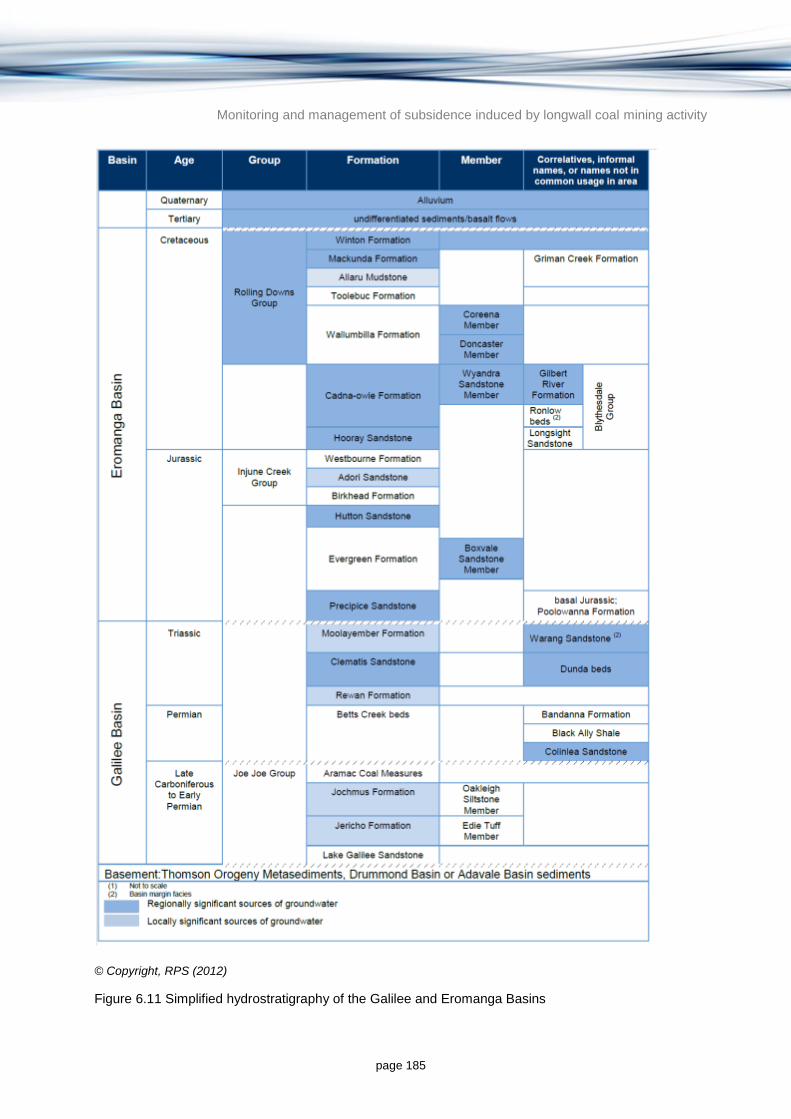
Monitoring and management of subsidence induced by longwall coal mining activity
page 185
© Copyright, RPS (2012)
Figure 6.11 Simplified hydrostratigraphy of the Galilee and Eromanga Basins
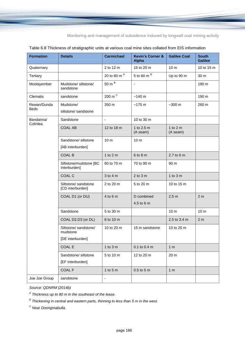
Monitoring and management of subsidence induced by longwall coal mining activity
page 186
Table 6.8 Thickness of stratigraphic units at various coal mine sites collated from EIS information
Formation Details Carmichael Kevin’s Corner & Alpha
Galilee Coal South Galilee
Quaternary 2 to 12 m 15 to 20 m 10 m 10 to 15 m
Tertiary 20 to 80 m A 5 to 60 m
B Up to 90 m 30 m
Moolayember Mudstone/ siltstone/ sandstone
50 m B
- 190 m
Clematis sandstone 200 m C
~140 m 190 m
Rewan/Dunda Beds
Mudstone/
siltstone/ sandstone
350 m ~175 m ~300 m 260 m
Bandanna/ Colinlea
Sandstone - 10 to 30 m
COAL AB 12 to 18 m 1 to 2.5 m (A seam)
1 to 2 m (A seam)
Sandstone/ siltstone
[AB Interburden]
10 m 10 m
COAL B 1 to 2 m 6 to 8 m 2.7 to 6 m
Siltstone/mudstone [BC Interburden]
60 to 70 m 70 to 90 m 90 m
COAL C 3 to 4 m 2 to 3 m 1 to 3 m
Siltstone/ sandstone [CD interburden]
2 to 20 m 5 to 20 m 10 to 15 m
COAL D1 (or DU) 4 to 6 m D combined
4.5 to 6 m
2.5 m 2 m
Sandstone 5 to 30 m 10 m 10 m
COAL D2.D3 (or DL) 8 to 10 m 2.5 to 3.4 m 2 m
Siltstone/ sandstone/ mudstone
[DE interburden]
10 to 20 m 15 m sandstone 10 to 20 m
COAL E 1 to 3 m 0.1 to 0.4 m 1 m
Sandstone/ siltstone
[EF Interburden]
5 to 10 m 12 to 20 m 20 m
COAL F 1 to 5 m 0.5 to 5 m 1 m
Joe Joe Group sandstone -
Source: QDNRM (2014b)
A Thickness up to 80 m in the southeast of the lease.
B Thickening in central and eastern parts, thinning to less than 5 m in the west.
C Near Doongmabulla.
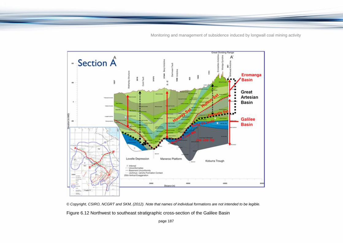
Monitoring and management of subsidence induced by longwall coal mining activity
page 187
© Copyright, CSIRO, NCGRT and SKM, (2012). Note that names of individual formations are not intended to be legible.
Figure 6.12 Northwest to southeast stratigraphic cross-section of the Galilee Basin

Monitoring and management of subsidence induced by longwall coal mining activity
page 188
© Copyright, CSIRO, NCGRT and SKM, (2012). Note that names of individual formations are not intended to be legible.
Figure 6.13 Southwest to northeast stratigraphic cross-section of the Galilee Basin

Monitoring and management of subsidence induced by longwall coal mining activity
page 189
Marsh et al. (2008) provide some indication of the hydrostratigraphic nature of the lower units of the Galilee Basin formations:
Lake Galilee Sandstone: even though this formation has a sandstone lithology, quartz cementation has virtually reduced the porosity and permeability to zero, hence this unit can be considered an aquitard.
Jericho Formation: this formation is predominantly comprised of siltstone and mudstone, and is considered to act as an aquitard.
Jochmus Formation: this formation is comprised of sandstone in the upper and lower parts, with a middle part composed of tuff with minor mudstones and siltstone. Marsh et al. (2008) considers that the sandstones within the Jochmus Formation ‘appear to be more porous and permeable than the formations below’, but suggests there may be a high proportion of clay present (related to volcanic activity during deposition) but likely to be less in the Lovelle Depression. Permeabilities for this unit cited in Marsh et al. (2008) of zero to 1634 millidarcys (mD; approximately zero to 1.6 m per day) are not indicative of an aquifer from a typical water resource perspective, but indicate higher permeability than in underlying aquitards.
The Permian Coal Measures (Betts Creek Beds and Aramac Coal Measures) represent aquifers of poor to moderate permeability based on the sandstone layers within these units. The Rewan Formation is comprised of interbedded sandstone, mudstone and siltstone. However, the sandstone is predominantly labile, has an abundance of clay and silt, and hence poor permeability (Moya 2011) and as a result the Rewan Formation is considered to act as an aquitard.
The overlying Clematis Sandstone is the most significant aquifer within the Galilee Basin and is part of the GAB sequence. It consists of sandstone with minor siltstone and mudstone. The Clematis Sandstone is a useful aquifer and is present below much of the Eromanga Basin in the central GAB. There are some users tapping this aquifer in the Galilee Basin, predominantly in the east, where the aquifer is at its shallowest. The contemporaneous Warang Sandstone is also a potential aquifer with a median hydraulic conductivity of approximately 0.1 m per day but 10 per cent of values are over 1 m per day (CSIRO, NCGRT & SKM 2012).
The Moolayember Formation is an aquitard which is considered highly prospective as a sealing unit for potential carbon dioxide storage in the Galilee Basin (Marsh et al. 2008). It consists of mudstone with minor siltstone and sandstone (Scott et al. 1995). Marsh et al. (2008) cited a range of permeability for this formation of zero to 503 mD and an average of 81 mD (approximately 0.1 m per day). The hydraulic conductivity values estimated for this formation are not necessarily consistent with the hydraulic conductivity typically observed in an aquitard; however, the dataset behind these numbers is very small.
The Galilee Basin sequence ends with the Moolayember Formation, and after a period of compression and erosion, deposition started again in the Early Jurassic with the basal units of the Eromanga Basin. The Eromanga Basin comprises some significant aquifers. These can be divided into the deeper Jurassic units and the shallower Cretaceous units. The main Jurassic aquifers include the Hutton Sandstone, Cadna-Owie Formation and Hooray Sandstone all of which are GAB aquifers. The main Cretaceous aquifers are the Winton and Mackunda Formations which include unconfined to confined aquifers.
Tertiary and Quaternary alluvial deposits overlie the Mesozoic units. The Tertiary units consist of clays, some sand and occasional gravels (QDNRM 2014b). In some places the Tertiary units directly overlie the Permian Coal Measures where they come close to the surface.

Monitoring and management of subsidence induced by longwall coal mining activity
page 190
Quaternary alluvial deposits overlie the Tertiary sediments along major stream lines. Depths of Quaternary (alluvial) material range from two to 15 m and Tertiary thickness ranges from 20 to 80 m (QDNRM 2014b).
6.3.2 Coal resources
Late Permian, coal-bearing strata of the Galilee Basin subcrop are found in a linear, north-trending Belt in the central portion of the exposed section of the basin and are essentially flat lying (dip estimated at one to two degrees to the west around the southern coal mines and approximately two to four degrees to the west around the Carmichael mine to the north (QDNRM 2014a). The sequence of coal seams has a cumulative thickness of approximately 14 to 25 m. The six seams (A to F) are separated by intervals containing sandstones, siltstones and mudstones. Interburdens vary in thickness from approximately 5 to 90 m. The individual coal seams vary in thickness from 0.1 to 8 m, locally splitting (METServe 2012).
The seams from oldest to youngest are (METServe 2012):
F seam: 0.5 to 5 m thick, excessively banded and poor quality
E seam: 0.1 to 0.4 m thick
D seam: 4.5 to 7.5 m thick with stone bands totalling up to 3 m thick (4.5 m extraction)
C seam: 2 to 3 m thick with claystone bands totalling 0.2 m thick (2.5 m extraction)
B seam: six to 8 m thick separated into four plies by tuffaceous claystone, high ash content
A seam: 1 to 2.5 m thick but generally 1 m thick.
The economic seams include the B, C and D coal seams via open cut methods with parts of the B and D seams viable via the longwall mining method. Both seams are within the Coinlea Sandstone unit. Both Carmichael Coal Mine and Galilee Coal Mine are proposing to target the B seam in addition to the D seam (QDNRM 2014a).
6.3.3 Groundwater in the Galilee Basin
6.3.3.1 Groundwater occurrence and use
The generalised hydrostratigraphy for the Galilee Basin is shown in Table 6.9 including a summary of groundwater quality, bore yield, use and management.
The RPS (2012) assessment of a search of the QDNRM (2012d) groundwater database found that the most significantly exploited groundwater resources in the Galilee Basin study area are located within the shallow Eromanga Basin; the Hutton Sandstone, Hooray Sandstone and Cadna-Owie Formation. This report also identifies that significant groundwater resources are produced from the aquifers in the shallow Rolling Downs sediments and that there are useable volumes of groundwater in the alluvial deposits associated with the major rivers and some Tertiary sediments and volcanics.

Monitoring and management of subsidence induced by longwall coal mining activity
page 191
Table 6.9 Generalised hydrostratigraphy of the Galilee Basin including aquifer quality, yield and management
Basin Group Formation Description Hydrostatic classification
Groundwater quality Groundwater yield Use and management
Surficial deposits
Recent alluvium along major river systems
Sands, silts and clays Local unconfined aquifers
TDS from 45 observations: Min 47.5 mg/L, Max 4380 mg/L, Average 789 mg/L
From 4 observations: Min 0.09 L/s, Max 5.44 L/s, Average 2.24 L/s
An important source of groundwater in the area with approximately 1400 water bores screened in the alluvium in the RPS Galilee study area and 200 water bores screened in the Tertiary deposits (QDNRM 2012a). 25 per cent of all bores (that have an attributed aquifer) tap these units (comparatively few of these are in the Tertiary Basalt). The bores tapping the alluvium are located in the north (around Hughenden), the east (around Alpha) and the south (around Augathella and Charleville). The bores tapping Tertiary sediments are largely restricted to the eastern section of the study area
East of the GAB, groundwater resources are managed under the Highlands Sub-artesian Area. To the west, groundwater in the alluvium and Tertiary sediments is managed under the GAB Sub-artesian Area.
Tertiary deposits Sediments and basalts Aquifers TDS from 248 observations: Min 118 mg/L, Max 14 211 mg/L, Average 1074 mg/L
1 observation at 29.00 L/s
Eromanga Rolling Downs Group
Winton Formation Sandstone, siltstone, mudstone, minor conglomerate
Aquifer TDS from 37 observations: Min 290 mg/L, Max 17 073 mg/L, Average 4253 mg/L
No data QDNRM (2012d) attributes 1900 water bores as tapping these formations in the RPS Galilee study area. The bores are spread in a northwest to southeast trending belt in two large areas. The northern most bores are centred on Winton and the southernmost bores are located between Windorah in the west and Blackall and Augathella in the east.
Formations are not listed in GAB management units.
Mackunda Formation Sandstone and siltstone
Aquifer TDS from 31 observations: Min 310 mg/L, Max 7652 mg/L, Average 2591 mg/L
1 observation at 0.03 L/s
Allaru Mudstone Mudstone, siltstone, limestone and some sandstone
Aquitard/ local aquifer
1 observation at 640 mg/L No data Considered to be locally important source of groundwater with more than 30 bores stretching in a north-south belt in the southeast extending east of Tambo, Augathella and Charleville.
Formation not listed in GAB management units.
Toolebuc Formation Limestone, shale and coquinite
Aquitard No data No data No bore data.
Listed in GAB management units: Barcaldine South 1, Barcaldine West 1, Central 1, Flinders 1, Flinders East 1, Warrego East 1 and Warrego West 1
Wallumbilla Formation
Siltstone, mudstone and sandstone
Aquitard with local aquifer members
TDS from 49 observations: Min 154 mg/L, Max 42 096 mg/L, Average 154 mg/L
No data Approximately 150 bores tapping this formation stretch in a northwest to southeast trending belt that extends to the southeast of the basin with a concentration of bores between Tambo and Charleville.
Listed in GAB management units: Barcaldine North 1, Barcaldine South 1, Barcaldine West 1, Central 1, Flinders 1, Flinders East 1, North West 1, Warrego East 1 and Warrego West 1
Cadna-Owie Formation
Sandstone and siltstone
Aquifer TDS from 1 observation in the Wyandra Sandstone Member 392 mg/L
From 3 observations in the Wyandra Sandstone Member: Min 1.58 L/s, Max 2.93 L/s, Average 2.04 L/s
Fewer than 30 bores tapping this formation mostly located in the southeast near Blackall, Tambo, Augathella and Charleville.
Listed in GAB management units: Barcaldine North 2, Barcaldine South 2, Barcaldine West 2, Central 2, Flinders 2, Flinders East 2, Warrego East 2 and Warrego West 2.
Hooray Sandstone Sandstone, siltstone, conglomerate, mudstone and coal
Aquifer TDS from 139 observations: Min 161 mg/L, Max 9613 mg/L, Average 714 mg/L
From 61 observations: Min 0.05 L/s, Max 40.00 L/s, Average 10.18 L/s
Approximately 600 bores tap this formation forming a broad northwest to southeast trending belt that traverses the basin and extends southeast across Blackall, Tambo, Augathella and Charleville. Also high concentration of bores near Julia Creek and Richmond.
Listed in GAB management units: Barcaldine North 2, Barcaldine South 2, Barcaldine West 2, Central 3, Flinders 2, Flinders East 2, North West 2, Warrego East 3 and Warrego West 3.

Monitoring and management of subsidence induced by longwall coal mining activity
page 192
Basin Group Formation Description Hydrostatic classification
Groundwater quality Groundwater yield Use and management
Injune Creek Group
Westbourne Formation
Fine sandstone, siltstone, claystone and coal
Aquitard TDS from 7 observations: Min 138 mg/L, Max 1133 mg/L, Average 570 mg/L
1 observation at 40 L/s More than 160 bores tap the Injune Creek Group in a broad northwest to southeast trending belt across the basin from Blackall to Richmond.
Listed in GAB management units: Barcaldine East 1, Barcaldine North 2, Barcaldine South 3, Barcaldine West 3, Central 4, Flinders 3, Flinders East 3, North West 2, Warrego East 4 and Warrego West 4.
Adori Sandstone Sandstone and siltstone
Aquifer TDS from 14 observations: Min 200 mg/L, Max 3480 mg/L, Average 616 mg/L
From 10 observations: Min 0.81 L/s, Max 52.55 L/s, Average 11.82 L/s
Birkhead Formation Sandstone, siltstone and mudstone
Aquitard TDS from 2 observations: Min 410mg/L, Max 453 mg/L, Average 432 mg/L
From 6 observations: Min 0.01 L/s, Max 8.51 L/s, Average 1.51 L/s
Hutton Sandstone Sandstone, siltstone, coal
Aquifer TDS from 313 observations: Min 18.5mg/L, Max 1648 mg/L, Average 386 mg/L
From 106 observations: Min 0.02 L/s, Max 50.00 L/s, Average 11.98 L/s
More than 600 bores tap this formation in the study area spread in a northwest to southeast trending belt that traverses the basin extending to the southeast across the Blackall, Tambo and Augathella areas. The densest bores are located where the Hutton Sandstone occurs at a shallow depth.
Listed in GAB management units: Barcaldine East 2, Barcaldine North 2, Barcaldine South 4, Barcaldine West 4, Central 5, Flinders 4, Flinders East 4, North West 2, Warrego East 5 and Warrego West 5.
Evergreen Formation Sandstone, mudstone, siltstone
Aquitard (although Boxvale Sandstone Member is local aquifer)
No Data From 4 observations in the Boxvale Sandstone Member: Min 2.37 L/s, Max 73.43 L/s, Average 38.01 L/s
Fewer than 30 bores tapping this formation mostly located in the far east of the basin. Listed in GAB management units: Barcaldine East 2, Barcaldine South 4, Barcaldine West 3, Central 5, North West 2, Warrego East 5 and Warrego West 5.
Precipice Formation Sandstone Aquifer TDS from 1 observations 266 mg/L
From 13 observations: Min 0.04 L/s, Max 24.46 L/s, Average 7.12 L/s
More than 60 bores tapping this formation in the area located in the eastern to south-eastern section of the basin.
Listed in GAB management units: Barcaldine East 3, Barcaldine South 5 and Warrego East 6.
Galilee Moolayember Formation
Mudstone with minor siltstone and sandstone
Aquitard TDS from 15 observations: Min 229 mg/L, Max 47 320 mg/L, Average 12 904 mg/L
From 5 observations: Min 0.21 L/s, Max 10.59 L/s, Average 4.38 L/s
Approximately 40 bores in the area tap this formation and are located in the eastern section of the basin where formation is shallowest. Listed in GAB management areas: Barcaldine East 4, Barcaldine North 3, Barcaldine West 5, Flinders East 5, Warrego East 7, and Warrego West 7.
Clematis Sandstone Quartzose sandstone with minor siltstone and mudstone
Aquifer TDS from 31 observations: Min 102 mg/L, Max 19 195 mg/L, Average 1895 mg/L
From 8 observations: Min 0.04 L/s, Max 24.46 L/s, Average 7.12 L/s
More than 100 bores tap this formation in the study area with the majority of bores located in the eastern section of the basin where formation is shallowest.
Listed in GAB management areas: Barcaldine East 4, Barcaldine North 3, Central 7, Flinders East 5, Warrego East 7, and Warrego West 7.
Rewan Formation Interbedded sandstone (high proportion of clay and silt), mudstone and siltstone
Aquitard TDS from 4 observations: Min 249 mg/L, Max 6036 mg/L, Average 1786 mg/L
1 observation in the Dunda Beds (Koburra Trough at 1.00 L/s
Approximately 20 bores tap the Dunda Beds (Koburra Trough) located in the eastern section of the basin where formation is shallowest.
Listed in GAB management areas: Barcaldine East 4, Central 7, Warrego East 7 and Warrego West 7.
Betts Creek Beds Interbedded coal and sandstone, siltstone and mudstone
Poor to moderate permeability aquifer
TDS from 2 observations: Min 360 mg/L, Max 1620 mg/L, Average 990 mg/L
No data Approximately 50 bores tap this formation in the study area located in the far eastern section of the basin where formation is shallowest.
Aquifer not listed in GAB management areas. East of the GAB, groundwater resources are managed under the Highlands Sub-artesian GMA.

Monitoring and management of subsidence induced by longwall coal mining activity
page 193
Basin Group Formation Description Hydrostatic classification
Groundwater quality Groundwater yield Use and management
Joe Joe Group
Aramac Coal Measures
Interbedded coal and sandstone
Poor to moderate permeability aquifer
TDS from 11 observations: Min 675 mg/L, Max 24 790 mg/L, Average 3389 mg/L
No data Approximately 30 bores tap this formation in the study area located in the far eastern section of the basin around Alpha where formations are shallowest.
Joe Joe Group formations not listed in GAB management areas. East of the GAB, groundwater resources are managed under the Highlands Sub-artesian GMA.
Jochmus Formation Sandstone in the upper and lower parts, with a middle part of tuff with minor mudstones and siltstone
Aquitard (although sandstone layers have higher permeabilities)
TDS from 3 observations: Min 809 mg/L, Max 900 mg/L, Average 843 mg/L
No data
Jericho Formation Siltstone and mudstone
Aquitard TDS from 2 observations: Min 2360 mg/L, Max 6840 mg/L, Average 4600 mg/L
No data
Lake Galilee Sandstone
Highly cemented sandstone
Aquitard TDS from 1 observations 13 500 mg/L
No data
Source: modified from RPS (2012)

Monitoring and management of subsidence induced by longwall coal mining activity
page 194
6.3.3.2 Groundwater management
Groundwater in the GAB aquifers is managed under the Water Resource (Great Artesian Basin) Plan 2006 (Queensland Government 2006). The purpose of the Plan is to define the availability of water in the area, provide a framework for managing and abstracting water sustainably and to identify priorities and mechanisms for dealing with future water requirements (Queensland Government 2006). The Plan identifies 25 GMAs in the GAB of which the Galilee Basin covers four GMAs (Flinders, Flinders East, Barcaldine West and Barcaldine North). All artesian groundwater extraction from GAB aquifers is licensed, including that used for stock and domestic purposes (no volumetric entitlements are associated with stock and domestic licences). For non-artesian areas of the GAB, a licence is not required for domestic purposes.
East of the GAB, groundwater in the alluvium, Tertiary sediments, Betts Creek Beds and Jochmus Formation are managed under the Highlands Sub-artesian GMA. Licences are required for the take of groundwater for purposes other than stock or domestic.
6.3.3.3 Groundwater flow
Groundwater recharge, discharge and flow as well as aquifer connectivity in the Galilee Basin was described in CSIRO, NCGRT and SKM (2012). A summarised version is provided below.
There is very limited information in the literature on recharge processes, areas and rates in the Galilee Basin. Regional studies have identified that the recharge area of the GAB occurs mainly along the eastern margins of the basin where the lower Cretaceous-Jurassic aquifers outcrop along the Great Dividing Range (Habermhel 1980). A major regional study of recharge rates to GAB intake beds was undertaken by Kellett et al. (2003). The study categorised recharge into three main processes: diffuse recharge (0.03 to 2.4 mm per year) related to average rainfall conditions; preferred pathway flow recharge (0.5 to 28 mm per year) associated with high intensity rainfall events; and localised recharge from stream or inter-aquifer leakage (up to 30 mm per year). The study concluded that preferred pathway flow is considered the dominant recharge mechanism for GAB intake beds and that rainfall events in the order of 200 mm per month or more are required. The study focussed on the Hooray Sandstones (and equivalents), and to a lesser degree the Hutton and Adori Sandstones and there is therefore a data gap in terms of recharge (in the outcrop and subcrop areas) to the Triassic (Clematis Sandstone) and Permian formations (Colinlea Sandstone, Aramac Coal Measures and Betts Creek Beds) of the Galilee Basin. However, it is important to recognise that all longwall coal mines in the Galilee Basin to date are to the east of the westernmost extent of the GAB recharge areas (Figure 6.4).
References to recharge in the Galilee Basin include Marsh et al. (2008), which states that groundwater recharge into the overlying Eromanga Basin and Triassic part of the Galilee sequence occurs in the northeast with generally south-westerly flow. Groundwater investigations as part of the Alpha Coal Project (JBT 2010) on the eastern edge of the Galilee Basin concluded that groundwater in the Permian Coal Measures occurs under confined conditions in the western area of the Alpha Coal MLA, potentially becoming unconfined to the east of Lagoon Creek in the outcrop area of the Colinlea Sandstone (lower Betts Creek Beds). This study also included a review of hydrographs which did not indicate aquifer recharge in response to high rainfall over the 2009/10 wet season (JBT 2010). It is therefore assumed that infiltration through the Colinlea Sandstone outcrop is limited, unless there is sufficient rainfall to saturate the rock profile.

Monitoring and management of subsidence induced by longwall coal mining activity
page 195
JBT (2010) discuss a number of recharge mechanisms at the Alpha Coal Project site including:
direct recharge to outcrop areas
diffuse recharge along the Great Dividing Range
flood recharge from Lagoon Creek
diffuse recharge through surface Tertiary sediments.
In the west of the Alpha Coal Project area, the potentiometric surface of the upper Colinlea (C-D sandstone) is higher than the potentiometric surface deeper in the formation (D-E sandstone), indicating downward flow potential within this formation (JBT 2010). For shallow aquifers at the site, evidence is presented in support of Great Dividing Range diffuse recharge being the most important recharge mechanism, and direct recharge from the outcrop/subcrop area of Colinlea Sandstone being less regionally significant. However, JBT (2010) acknowledges that this recharge process may be important for deeper units within the Colinlea Sandstone Aquifer.
SKM (2009c) indicated that Permian aquifer zones may be recharged predominantly by vertical leakage from the overlying Tertiary and younger sediments. SKM (2009c) suggested that it is unlikely that a pressure gradient exists towards the west in the confined sections of the Permian aquifers, and instead it is proposed that a gradient to the north, following a similar direction to the groundwater flow in the overlying Tertiary sediments, is more likely in these units. SKM (2009c) concluded that ‘as the mine lease area is located to the east of the recognised GAB recharge zone, a confirmed pressure gradient in the Permian aquifer zones to the west would be required to suggest that the Galilee Basin forms part of the greater recharge zone of the GAB’. Generally, these studies indicate uncertainty as to whether recharge to the Triassic and Permian aquifer outcrops or subcrops would follow local topographic gradients or if recharge would follow the regional stratigraphic westerly dip of these formations. There has been no information identified in the literature on the significance of vertical leakage as a recharge process to the formations of the Galilee Basin.
There is also very limited information in the literature on discharge processes in the Galilee Basin. Some information exists relating to local discharge processes in the outcrop and subcrop areas of the basin although it is apparent that processes are still not well understood. RPS (2012) referred to the GAB recharge springs (springs which occur in the same outcropping unit that the recharge occurred) in the Galilee Basin occurring in association with the intake bed outcrops and subcrop areas. The Alpha Coal Project (JBT 2010) also reported the presence of (recharge) springs within the wider study area, although the dominant groundwater discharge processes in the MLA were considered to be towards Lagoon Creek (and either to wetlands associated with the creek or to the alluvial sediments of the creek). SKM (2009c) reached similar conclusions for the South Alpha MLA where discharge north towards the local river system (Belyando River) was considered likely. The studies generally appear to regard relatively local discharge processes to be the dominant form of groundwater discharge in the far eastern part of the Galilee Basin (where units of the Galilee Basin outcrop or subcrop). This appears to imply a groundwater divide where some recharge is directed west towards the deeper units in the central parts of the basin.
There was no information identified on discharge processes in the main parts of the basin (i.e. to the west where it underlies the Eromanga Basin). CSIRO, NCGRT and SKM (2012) suggested that, given the submerged nature and geometry of the basin, groundwater discharge is likely to be some combination of diffuse vertical discharge through confining beds

Monitoring and management of subsidence induced by longwall coal mining activity
page 196
to overlying formations (ultimately to the Eromanga Basin) and subsurface discharge to neighbouring sedimentary basins or adjoining basement units. The relative importance and spatial distribution of these processes is unknown.
RPS (2012) conducted a search and analysis of QDNRM (2012d) groundwater database bores in the Galilee Basin and produced groundwater elevation contour maps for the Eromanga Basin aquifer units. RPS (2012) interpreted recharge areas, discharge areas and groundwater flow direction from these maps as summarised below:
Rolling Downs Group: Two major potentiometric surface highs exist in these units; one in the northeast from Hughenden to Lake Galilee and one in the southeast over the Springsure Shelf. These major potentiometric surface highs correspond with the intake beds for the Rolling Downs Group. A smaller isolated high over the Maneroo Platform south of Winton correspond to the Forsyth Ranges, an area of Quaternary alluvium and Tertiary sediments. Groundwater recharge may be occurring in this area due to the shallow surface materials retaining water long enough to allow recharge to the Rolling Downs Group (as opposed to other areas where runoff occurs). Two large groundwater lows (one over the Maneroo Platform and one at the southern end of the Lovelle Depression in the west) parallel major river systems (the Thomson and Diamantina Rivers respectively), suggesting that there is groundwater discharge to the river systems. There is a similar, less pronounced potentiometric surface low associated with Blackwater Creek in the southeast. Overall groundwater flow in these units is to the west across the Galilee Basin.
Cadna-Owie Formation and Hooray Sandstone Aquifers: Potentiometric surface highs exist northeast of Hughenden, east of Amarac and over the Springsure Shelf (no groundwater high exists under the Forsyth Ranges in this unit). Groundwater flow is predominately to the west although there is a significant northward component of flow associated with the Flinders River. This suggests that small areas of the Cadna-Owie Formation and Hooray Sandstone near to recharge areas drain into the Carpentaria Basin. Generally, groundwater flow in this system is from the Springsure Shelf and western side of the Great Dividing Range towards the west and the Diamantina River.
Hutton Sandstone Aquifer: The major potentiometric high in the Hutton Sandstone is over the Springsure Shelf with the pronounced highs in the north and east seen in overlying aquifers not present in this unit. Recharge over the Springsure Shelf flows westward and does not appear to recharge the unit in the northern portion of the basin. Groundwater in the Hutton Sandstone in the northern and north-western portions of the basin is likely to have entered along the formation edge between Hughenden and Lake Galilee. Potentiometric lows in this unit are found in the west of the basin with the major low occurring in an area where the Hutton Sandstone unconformably overlies the Permian coal measures. The discharge areas of this formation are not identified in the RPS (2012) and further investigation is recommended. Groundwater use, groundwater discharge to the surface or discharges to other basins are suggested as potential mechanisms for groundwater discharge from the Hutton Sandstone.
CSIRO, NCGRT and SKM (2012) stated that aquifer connectivity across the Galilee Basin has had little attention with the focus of most investigations being on the geology of the basin and reservoir characteristics of the Permian units. In particular, the hydraulic connectivity of the Permian coal seams and the overlying Eromanga units has not been studied in any detail. The hydrostratigraphy of the basin indicates that there are large areas where significant thicknesses of (apparently) low permeability formations (i.e. Rewan and Moolayember) separate the Permian coal measures from the overlying Eromanga Basin aquifers. The existence of these ‘sealing’ formations is one of the reasons why the basin was recommended
Monitoring and management of subsidence induced by longwall coal mining activity
page 197
as a potential site for geosequestration of carbon dioxide, and further investigations into these formations have been recommended (Marsh et al. 2008).
The general understanding of separation between the Galilee Basin units and the Eromanga units is supported by the fact that the basin has relatively few structural features such as major faults and where faulting is present they are not continuous across the Permian units and into the overlying Jurassic-Cretaceous formations (although this is based on a limited number of local assessments; CSIRO, NCGRT & SKM 2012). Furthermore, preliminary geochemistry assessments suggest the Permian units are hydraulically separate from the overlying aquifers and limited local groundwater modelling suggests that the overlying aquitard will limit connectivity (CSIRO, NCGRT & SKM 2012).
RPS (2012) state that Eromanga Basin aquifers are typically not in direct hydraulic connection with the Permian Coal Measures, with the Moolayember Formation and the Clematis Sandstone usually forming the interburden between the Hutton Sandstone and the Permian Coal Measures.
The general conclusion from the studies listed above (Marsh et al. 2008; RPS 2012) of limited connectivity between the Permian strata and the overlying aquifers is challenged by CSIRO, NCGRT and SKM (2012) for the following reasons:
Key confining units are not continuous across the basin and whilst there will be areas where the likelihood of significant connectivity is low, other areas exist where the risk of connectivity will be much higher. The top of the Moolayember Formation is an unconformable surface which was subject to a long period of erosion, and consequently in parts of the basin the formation is thin or absent. This leaves potential for connection between the Permian units and overlying Eromanga aquifers (e.g. Hutton Sandstone). The areas with the greatest potential for this are to the northwest of the Aramac Trough and along the western margin of the southern Galilee Basin (Marsh et al. 2008).
The Warang Formation (found mainly in the north of the basin) is comprised mainly of sandstone and interfingers with the entire Triassic sequence. As it is in contact with the Eromanga Basin, this makes the Warang Formation a potential transmission unit between the Permian units and low salinity aquifers.
The southern Galilee Basin has been poorly studied and is little understood compared with the northern half of the basin.
Permeability of the key aquitards in the basin is based on a very limited dataset and there remains uncertainty regarding appropriate hydraulic conductivity values to use in these key formations. Existing permeability datasets in the Galilee Basin to date are mostly based on point-scale testing (predominantly laboratory tests and some drill stem tests). This is a significant limitation as it is generally accepted that permeability increases with increasing scale of measurement.
The hydraulic behaviour of faults has not been studied in the basin and requires further investigation.
Cumulative impacts across the Galilee Basin need to be assessed as multiple operations may alter potential connectivity compared to developments assessed in isolation.
CSIRO, NCGRT and SKM (2012) conclude that significant parts of the Galilee Basin may represent areas of relatively low inter-aquifer (and surface) connectivity, but there are areas where the geology suggests vertical connection is much higher. Furthermore, even in areas where connectivity risks appear low, there are significant data gaps that require filling to confirm this conclusion.
Monitoring and management of subsidence induced by longwall coal mining activity
page 198
All of the above studies have been undertaken to assess the impact of depressurisation of the coal measures from coal seam gas extraction on overlying aquifers. Even though the mechanism for impact on overlying aquifers from longwall coal mining is quite different from coal seam gas extraction, these studies provide important insights into the pre-mining state of the hydraulic connection between the Permian Coal Measures and overlying aquifers. The potential impact of longwall coal mining on the overlying aquifers is discussed in Section 6.3.3.5.
6.3.3.4 Groundwater and surface water interaction
The RPS (2012) potentiometric surface contour maps suggest that groundwater is discharged from the Rolling Downs Group to the Thomson River southwest of Longreach and the Diamantina River. Maps for the Cadna-Owie Formation and Hooray Sandstone indicate a portion of groundwater flows to the north towards the Flinders River system, suggesting that small areas of the Cadna-Owie Formation and Hooray Sandstone near to recharge areas drain into the Carpentaria Basin. The Doongmabulla Springs and the Carmichael River are thought to be discharge areas for the Clematis Sandstone (QDNRM 2014b).
More information on springs, wetlands and rivers in the Galilee Basin can be found in Section 6.3.5.2.
6.3.3.5 Potential impacts on groundwater resources
The main coal deposits targeted for mining in the Galilee Basin are the Permian Betts Creek Beds and Aramac Coal Measures. Although these coal measures are poor aquifers, there are significant overlying aquifers which could potentially be affected by subsidence induced by longwall coal mining, the most significant of which are:
Galilee Basin: Clematis Sandstone and Warang Sandstone
Eromanga Basin: Jurassic Hutton Sandstone, Cadna-Owie Formation and Hooray Sandstone.
The potential for these aquifers to be affected by longwall coal mining of the underlying Permian Coal Measures is strongly dependent on the pre-existing hydraulic connection between these units and the degree of caving, fracturing and subsidence which may be induced by longwall mining.
CSIRO, NCGRT and SKM (2012) noted that:
‘…there has been relatively little assessment on aquifer connectivity across the Galilee Basin.’ and that in particular ‘…the hydraulic connectivity of the Permian coal seams and the overlying GAB units has not been studied in any detail’. That said, the authors observed that ‘there are large parts of the basin where significant thicknesses of (apparently) low permeability formations (Rewan and Moolayember) separate the Permian formations targeted for CSG/coal development from overlying aquifers’ but that ‘there are locations where the Moolayember Formation thins significantly or is absent, such that in some areas there is (effective) contact between the Permian Coal Measures and the Hutton Sandstone (via the Clematis Sandstone)’.
CSIRO, NCGRT and SKM (2012) also note that:
‘There is potential for depressurisation in Permian units deeper in the basin to propagate laterally to eastern parts of the basin, where these units outcrop/subcrop. The permeability of key aquitards in the Galilee Basin is based on a very limited dataset.

Monitoring and management of subsidence induced by longwall coal mining activity
page 199
Further, it is apparent that the hydraulic behaviour of faults has not been studied in the basin. Cumulative impacts across the Galilee Basin may alter potential connectivity compared to developments assessed in isolation.’
Irrespective of the natural hydraulic connection between coal seams and surrounding aquifers, longwall coal mining is likely to increase the hydraulic connection and may lead to adverse impacts on the groundwater resources of the GAB. Any proposal to undertake longwall coal mining of the Permian sediments of the Galilee Basin must assess the potential for changes to groundwater movement that may arise from subsidence and associated breaching of confining units that separate the coal seams from the overlying aquifers of the GAB.
Due to the lack of experience gained from operational longwall coal mines in the Galilee Basin, there has been little investigation, observation or prediction of the mining impacts on vertical connection between the mined coal seams and overlying aquifers and remains a key knowledge gap. However, there has been recent work undertaken for the Galilee Coal Mine by Waratah Coal to review the potential impact of longwall coal mine subsidence on the Clematis Sandstone Aquifer. The Galilee Coal Mine project is proposing underground workings targeting the B and D coal seams which extend beneath the Clematis Sandstone in places. Where mining is to be undertaken beneath the Clematis Sandstone, only the deeper D seam will be targeted (QDNRM 2014b). Subsidence modelling suggests that the extent of vertical fracturing is likely to be limited to the base of the Rewan Formation and, therefore, will have limited impact on the shallower Clematis Sandstone Aquifer (Waratah Coal 2013). The underground workings of other planned mines do not extend laterally under the Clematis Sandstone. South Galilee’s underground workings are approximately 2 km east of the Clematis Sandstone outcrop. The Kevin’s Corner underground workings are 6 km east of the Clematis Sandstone outcrop, while the Carmichael underground workings are about 2 km east of the visible Clematis Sandstone (QDNRM 2014b).
6.3.4 Geotechnical properties
The Galilee Basin is not well studied compared to the Sydney and Bowen Basins but the literature suggests that coal and overburden layers are likely to readily cave due to the lower bridging potential of the overburden lacking the presence of massively bedded units (URS 2012a and METServe 2012). However, this conclusion is based on observation of the geological profile in the absence of any measured subsidence data from longwall coal mining and, therefore, remains conjecture only.
As with the Bowen Basin, specific mine site geotechnical properties for proposed Galilee Basin mines are not publicly available but are, however, presented in some EISs. GVK’s Alpha Coal (URS 2010b) and Kevin’s Corner (URS 2012a) EISs contain some overburden and coal geotechnical properties. Key geometric and geotechnical parameters used for predicting subsidence (NCB 1966, 1975) based on the Alpha Coal and Kevin’s Corner Projects, for coal and overburden are presented in Table 6.10 and Table 6.11, respectively. The locations of Alpha and Kevin’s Corner mines are shown in Figure 6.2.
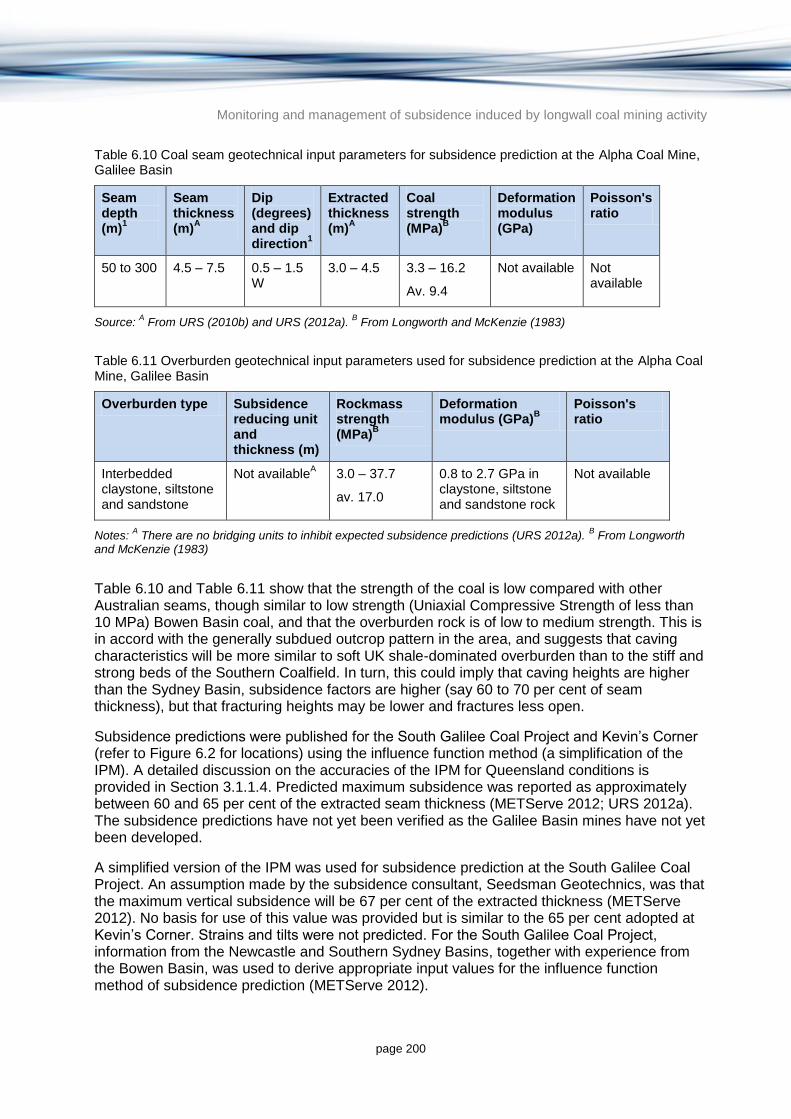
Monitoring and management of subsidence induced by longwall coal mining activity
page 200
Table 6.10 Coal seam geotechnical input parameters for subsidence prediction at the Alpha Coal Mine, Galilee Basin
Seam depth (m)
1
Seam thickness (m)
A
Dip (degrees) and dip direction
1
Extracted thickness (m)
A
Coal strength (MPa)
B
Deformation modulus (GPa)
Poisson's ratio
50 to 300 4.5 – 7.5 0.5 – 1.5 W
3.0 – 4.5 3.3 – 16.2
Av. 9.4
Not available Not available
Source: A From URS (2010b) and URS (2012a).
B From Longworth and McKenzie (1983)
Table 6.11 Overburden geotechnical input parameters used for subsidence prediction at the Alpha Coal Mine, Galilee Basin
Overburden type Subsidence reducing unit and thickness (m)
Rockmass strength (MPa)
B
Deformation modulus (GPa)
B
Poisson's ratio
Interbedded claystone, siltstone and sandstone
Not availableA 3.0 – 37.7
av. 17.0
0.8 to 2.7 GPa in claystone, siltstone and sandstone rock
Not available
Notes: A There are no bridging units to inhibit expected subsidence predictions (URS 2012a).
B From Longworth
and McKenzie (1983)
Table 6.10 and Table 6.11 show that the strength of the coal is low compared with other Australian seams, though similar to low strength (Uniaxial Compressive Strength of less than 10 MPa) Bowen Basin coal, and that the overburden rock is of low to medium strength. This is in accord with the generally subdued outcrop pattern in the area, and suggests that caving characteristics will be more similar to soft UK shale-dominated overburden than to the stiff and strong beds of the Southern Coalfield. In turn, this could imply that caving heights are higher than the Sydney Basin, subsidence factors are higher (say 60 to 70 per cent of seam thickness), but that fracturing heights may be lower and fractures less open.
Subsidence predictions were published for the South Galilee Coal Project and Kevin’s Corner (refer to Figure 6.2 for locations) using the influence function method (a simplification of the IPM). A detailed discussion on the accuracies of the IPM for Queensland conditions is provided in Section 3.1.1.4. Predicted maximum subsidence was reported as approximately between 60 and 65 per cent of the extracted seam thickness (METServe 2012; URS 2012a). The subsidence predictions have not yet been verified as the Galilee Basin mines have not yet been developed.
A simplified version of the IPM was used for subsidence prediction at the South Galilee Coal Project. An assumption made by the subsidence consultant, Seedsman Geotechnics, was that the maximum vertical subsidence will be 67 per cent of the extracted thickness (METServe 2012). No basis for use of this value was provided but is similar to the 65 per cent adopted at Kevin’s Corner. Strains and tilts were not predicted. For the South Galilee Coal Project, information from the Newcastle and Southern Sydney Basins, together with experience from the Bowen Basin, was used to derive appropriate input values for the influence function method of subsidence prediction (METServe 2012).

Monitoring and management of subsidence induced by longwall coal mining activity
page 201
In terms of depths and overburden geology, the mines of the Galilee Basin are more similar to those proposed in the Bowen Basin than to the NSW basins (METServe 2012). Consequently, Bowen Basin subsidence profile data has been used to predict subsidence for the South Galilee Coal Project.
There are generally no bridging units in the Galilee Basin to reduce the predictability of subsidence behaviour (URS 2012a). The overburden sequence at the South Galilee Coal Project consists of sandstones, mudstones and claystone with minor coal seams (Figure 6.3). From observations of the geological core and a review of the regional geology, the geotechnical consultant Golder Associates, assessed the overburden sequence at the South Galilee Coal Project as not containing massively bedded units (greater than 10 m thick) and consequently anticipated that it will cave readily during longwall operations (METServe 2012). Consequently, the maximum subsidence for a given seam extraction is predicted to be slightly higher than that predicted at the NSW Southern Coalfield, where the overburden depth is typically 400 m and up to 650 m and competent sandstone layers up to 200 m thick are within the overburden.
6.3.5 Surface water in the Galilee Basin
A desktop characterisation of surface water assets within the areas overlying economic coal measures of all of the Queensland coal basins was undertaken through a number of spatial analyses. The method is described in Section 6.2.5. The mapped surface water resources in the Galilee Basin including wetlands and GDEs are shown in Figure 6.13.
6.3.5.1 Surface water occurrence and use
The coal measures contained within the Galilee Basin are located on the eastern edge of the basin, along the Great Dividing Range (Figure 6.14). The range is fairly low in this region, with the landscape dominated by gently undulating hills and extensive plains, with some areas of steep and rolling low hills (GHD 2010). There are extensive areas of alluvium, with scattered areas of bedrock (GSQ 2012). Rivers within these basins are ephemeral and generally have alluvial braided channels, with a low gradient (GHD 2010).
The coal measures lie across the headwaters of three different water management catchments: the Flinders Catchment, the Cooper Catchment and the Burdekin Catchment. Rivers in the Cooper Catchment flow inland (southwest), while rivers in the Flinders Catchment flow to the Gulf of Carpentaria (north) and those in the Burdekin Catchment flow to the Pacific Ocean (northeast). The major watercourses are Torrens Creek, Warrigal Creek, and tributaries of the Belyando River.
Flows are highly variable on an annual and seasonal basis, with the majority of flow usually occurring between December and April. High flow events generally occur in late summer and early autumn and may occasionally cause flooding.
Surface water use is quite limited within the Galilee Basin, with some use for agricultural, and stock and domestic purposes. There are no major water storages within the Galilee Basin, although Jericho Weir is located close to the coal measures (QDNRM 2012c) and streamflow into the weir could potentially be affected.
6.3.5.2 GDEs
GDEs are ecosystems that are partially or completely dependent on groundwater for their existence or health. The GDE Atlas (Bureau of Meteorology 2013) was used to identify the

Monitoring and management of subsidence induced by longwall coal mining activity
page 202
main GDEs in the coal basins. The GDEs have been classified by the Bureau of Meteorology (2013) as either previously identified (through fieldwork or desktop studies) or their presence has been inferred through a combination of broad scale analysis, existing datasets and remote sensing methods. Areas of inferred GDEs are rated by the Bureau of Meteorology (2013) as either having low, moderate or high potential for groundwater interaction (i.e. a low, moderate or high likelihood that they are actually GDEs). While field verification of the potential GDE mapping has not taken place, the results have been reviewed by State and Territory representatives with groundwater and ecology knowledge of the mapped areas (Bureau of Meteorology 2013).
Jacobs undertook a spatial analysis of the GDEs present in the Queensland coal basins that are reliant on the surface expression of groundwater using the information in the GDE Atlas (Bureau of Meteorology 2013). The results of this analysis are summarised in Table 6.12 for the Galilee Basin and are presented spatially in Figure 6.14. The map shown in Figure 6.14 also presents the locations of current coal mine sites and potential future coal mine sites (Coal Resource Inferred Site).
Table 6.12 Galilee Basin estimated number of GDEs (reliant on the surface expression of groundwater) by coal basin
Area (km2)
Known GDEs
Inferred GDEs
High potential for groundwater interaction
Moderate potential for groundwater interaction
Low potential for groundwater interaction
14 600 44 105 815 342
The majority of known GDEs are located in the northern half of the basin, along the Torrens Creek, downstream of Lake Buchanan, P R Creek and in the vicinity of the Doongmabulla Springs (although these GDEs are quite small and may be difficult to identify at the basin scale). Lake Buchanan and Doongmabulla Springs are also listed in the Directory of Important Wetlands in Australia (Environment Australia 2001). There are also extensive areas which have been identified as having a moderate potential for GDE presence, particularly along the major watercourses in the north of the basin.
RPS (2012) note that the majority of the mapped springs in the Galilee Basin are located in the Springsure Shelf region with a smaller number located in the Barcaldine region. The spatial distribution of springs in the area suggests that they are predominately discharging from the Eromanga Basin aquifers north of Barcaldine and from the Galilee Basin aquifers over the Eastern Springsure Shelf (RPS 2012). No springs occur west of the first outcropping of the Toolebuc Formation. RPS (2012) claims that the springs are thought to be associated with shallow occurrences of the aquifers as opposed to regional faulting.

Monitoring and management of subsidence induced by longwall coal mining activity
page 203
Figure 6.14 Significant wetlands and GDEs in the Galilee Basin

Monitoring and management of subsidence induced by longwall coal mining activity
page 204
6.3.5.3 Significant wetlands
For the purpose of this report, significant wetlands are considered to be Ramsar listed wetlands (Section 6.2.5.3; Ramsar Convention 1999) and those which are listed in A Directory of Important Wetlands in Australia (DIWA; Environment Australia 2001).
Appendix B presents a summary of DIWA and Ramsar listed wetlands which are present in each of the coal basins (from DEW 2006). Although there are no Ramsar wetlands located in the Galilee Basin, there are a number of DIWA (nationally important) wetlands as shown in Figure 6.14 including Lake Buchnana, Cauckingbuna Swamp and Doongmabula Springs (Figure 6.14). The largest of these is Lake Buchanan, a saline lake which is an important area for waterfowl (Department of the Environment 2010). The Bingeringo Aggregation is located approximately 25 km downstream of the Galilee Basin, on Bully Creek, and may also potentially be affected by upstream mining activities.
6.3.5.4 Potential impacts on surface water resources
The conditions required for longwall coal mining subsidence to impact surface water are outlined in Sections 2.4 and Error! Reference source not found..
Alluvial rivers (as commonly found in the Galilee Basin) are more likely to be impacted by subsidence induced lowering of channel bed and changes in grade, than by bedrock cracking. While the relatively flat gradients of the watercourses in the Galilee Basin may reduce the likelihood of the transportation of solids such as sediment and rock (which act to keep cracks beneath watercourses open), it is also possible that the thick alluvial deposits in many of these watercourses may act to prolong dewatering if cracking occurs in the underlying bedrock (NSW Scientific Committee, 2005). The majority of the smaller watercourses and many of the larger watercourses in the Galilee Basin are ephemeral, and even the larger watercourses which are perennial exhibit a strongly seasonal flow regime. Therefore, these watercourses are considered vulnerable to subsidence impact.
Several recent EISs for projects in the Galilee Basin have identified areas of depression and instream changes as the key subsidence risks to surface water resources (Waratah Coal 2013; Hancock Galilee 2011; MSEC 2013). Areas of depression (leading to areas of ponding) are expected to result in reduced flows or changes to the existing flow paths, and can occur within watercourses and the surrounding catchment. This can impact on water quality, flow volumes, and flooding extent and flow paths. This issue is generally considered to be short to mid-term, with the depressions gradually filling with sediment (Hancock Galilee 2011).
The Kevin’s Corner EIS identified the potential for instream changes to watercourses, including increased sediment loads, increased erosion, changed sediment patterns, formation of an unstable channel system and destabilisation of stream beds and banks (Hancock Galilee 2011). In addition, areas of depression in the surrounding landscape are expected to create new surface water drainage paths, potentially leading to erosion and increased sediment input to downstream watercourses (Hancock Galilee 2011). The EIS notes that areas of ponding may lead to swamp development (Hancock Galilee 2011). This seems unlikely given the generally low rainfall across the region, but could occur where soil is sufficiently clayey and can retain water, or where a depression intersects the water table.
The Galilee Coal Project EIS identified increased instream ponding, leading to impacts on waterway stability, geomorphology and sediment transport processes (Waratah Coal 2013). This could result in the lowering of stream beds and banks, bank slumping, stream incision, stream widening and erosion (Waratah Coal 2013).

Monitoring and management of subsidence induced by longwall coal mining activity
page 205
The South Galilee Coal Project and the Carmichael Project have also predicted impacts on stream beds and instream processes and ponding in the subsided area (Seedsman Geotechnics 2012; MSEC 2013). Stream bed cracking, leading to erosion, is also expected to occur at the Carmichael Project (MSEC 2013).
6.3.6 Conceptual model
A conceptual model diagram for the Galilee Basin summarising the key surface and subsurface features described in Sections 6.3.1 to 6.3.5 is shown in Figure 6.15. The conceptual model diagram is not to scale and provides a diagrammatic representation of some of the concepts described in this report.

Monitoring and management of subsidence induced by longwall coal mining activity
page 206
Figure 6.15 Conceptual model diagram for the Galilee Basin illustrating some of the concepts described in Sections 6.3.1 to 6.3.5

Monitoring and management of subsidence induced by longwall coal mining activity
page 207
6.4 Differences between NSW and Queensland coal deposits
Much of the current understanding on the subsidence behaviour of longwall coal mines in Australia was developed in the Sydney Basin in NSW. However, with the planning of new longwall coal mines in the Galilee and Bowen Basins in Queensland, there is a strong need to determine whether the same conditions and behaviours exhibited in the Sydney Basin also apply to Queensland coal deposits.
This section provides a summary of the main differences in the geotechnical, groundwater and surface water characteristics of the Galilee and Bowen Basins in Queensland and the Sydney Basin in NSW.
6.4.1 Overview of NSW Coalfields
6.4.1.1 Groundwater
This section provides a short summary of the stratigraphy and hydrogeology of the Sydney Basin to allow comparison with the Bowen and Galilee Basins in Sections 3, 4 and 5. Given that the focus of this report is on Queensland coal deposits amenable to longwall coal mining, this section is an abbreviated summary only.
The generalised hydrostratigraphy of the coalfields of the Sydney Basin is summarised in Figure 6.16. Coal is currently and has historically been mined from Permian Coal Measures. Groundwater impacts arising from subsidence and deformation are typically seen in the overlying Triassic units. The Hawkesbury Sandstone and Narrabeen Group formations of the Triassic are found through most of the basin and are the principal hydrogeological units present. The Hawkesbury Sandstone is a 100 to 200 m thick multi-layered complex of sub-aquifers (perched water tables), which are interconnected to varying degrees by vertical joints and horizontal bedding planes. Groundwater moves, in effect, by stepping downwards through this ladder-like network of rock mass defects. As drilling proceeds, successively lower standing water levels are encountered, since perched groundwater drains into unlined boreholes. Its porosity and hydraulic conductivity are largely due to jointing, enhanced in places by solution cavities (sandstone karst; McNally & Evans 2007). Primary or inter-granular porosity is also of minor significance in the Southern Coalfield, which has the highest yielding wells in the basin (McNally & Evans 2007).
Well yields in the Hawkesbury Sandstone are generally less than one litre per second. Exceptionally high yielding bores have been reported in the Southern Highlands; yields as high as 40 litres per second (SCA 2006) were obtained from Sydney Catchment Authority well testing in the Upper Nepean Borefield project area. This yield is atypical (McNally & Evans 2007) and the sustainability of these pumping rates has yet to be demonstrated. At best, the Hawkesbury Sandstone would be considered as a weak aquifer system with local but limited potential for large-scale extraction.
The underlying Narrabeen Group sandstones are even poorer aquifers, perhaps one order of magnitude less permeable than the Hawkesbury Sandstone, and their porosity is entirely due to widely spaced fractures and bedding planes. The Narrabeen Group rocks are about 300 m thick, and composed of about two thirds sandstone to one third finer grained rocks such as shale. They are somewhat compartmentalised due to the presence of shale and claystone beds. The finer grained rocks are not much less permeable than the sandstones in the undisturbed state (Reid 1996), because under natural conditions they fracture in a brittle fashion like the sandstones. However under rapid loading and at large strains induced by mining subsidence they are believed to deform plastically and may also swell in contact with

Monitoring and management of subsidence induced by longwall coal mining activity
page 208
water. In this puttylike condition, it is argued, they may act as aquitards, effectively sealing the base of cracked sandstone formations (McNally & Evans 2007).
Outside the Sydney Basin significant alluvial aquifers occur in Tertiary and Quaternary alluvial deposits that are often of limited lateral extent and are therefore of local importance only. An exception is the alluvial aquifers of the Namoi Valley (within the Gunnedah Basin) that are extensive in area and thickness and form an important regional water resource. In parts of the valley the alluvial sediments sit above sediments of the GAB which in turn overly the Permian Coal Measures.
Nevertheless, it should be kept in mind that all NSW longwall mining to date has been carried out in the Sydney Basin, and most of this has been in the Southern Coalfield. Hence the published longwall subsidence data and hydrogeological consequences information from NSW is biased towards geological conditions in the Southern Coalfield. These conditions include:
a high proportion of brittle, thick and strong bridging sandstones in the mine overburden
high lateral in situ stresses interacting with steep and narrow gorges to create valley floor bulging and cliff instability
overlying fractured rock aquifers that are generally of low productivity and little used
thin soil profiles over massive sandstone, which result in near-surface strain concentrations and fracturing, with locally severe impacts on shallow groundwater.

Monitoring and management of subsidence induced by longwall coal mining activity
page 209
© Copyright, Retallack et al. (2011)
Figure 6.16 Stratigraphic framework for the major coal regions of the Sydney Basin

Monitoring and management of subsidence induced by longwall coal mining activity
page 210
6.4.1.2 Surface water
The Sydney Basin Bioregion covers significant portions of the Hawkesbury-Nepean, Hunter and Shoalhaven River systems. It also covers the smaller catchment of Lake Macquarie, Lake Illawarra, the Hacking, Georges and Parramatta Rivers, as well as parts of the headwaters of the Clyde and Macquarie Rivers. The larger of these rivers have their headwaters in the Blue Mountains and flow east to the Pacific Ocean. Rivers are generally short, with significant grade and permanent flow. This combination of characteristics has created a landscape of deep and steep gorges and cliff faces, with large areas of remnant sandstone and shale plateaus (DEH 2011). The southern and western edges of the basin contain cliff lines formed on the sandstones and conglomerates of the basal Permian sediments, with waterfalls commonly found on the escarpments (DEH 2011).
The basin has a population in excess of five million people (NSW DTIRE 2014) and is highly developed in terms of surface water resource use. It contains a number of significant water storages, with the major water users being the Sydney Water Corporation, local councils, irrigated agriculture, tourism, fishing and recreational users (NSW DTIRE 2014).
The Hawkesbury-Nepean catchment contains five major dams; Warragamba Dam, Upper Nepean Dam, Mangrove Creek Dam, Lyell Dam and Avon Dam (NSW Office of Water 2013). These are the main water supply storages for the Sydney metropolitan area, as well as Gosford and Wyong. Although the Hawkesbury-Nepean catchment is considered unregulated, streamflow in the river system is highly influenced by the presence of the major dams and numerous smaller water storages.
Other major water storages include Woronora Dam and Prospect Reservoir, in the Georges catchment (NSW Office of Water, 2012), as well as Glenbawn Dam, Glennies Creek Dam, Lostock Dam, Chichester Dam and Grahamstown Dam in the Hunter catchment (NSW Office of Water 2012). In combination, these dams have caused significant alterations to the pattern and volumes of streamflow available to the environment.
There are 13 wetlands of national significance in the Sydney Basin (Environment Australia 2001), as well as a number of wetlands of bioregional significance (DEH 2011). There are also two Ramsar-listed wetlands; Towra Point Nature Reserve (Botany Bay), and the Hunter Estuary Wetlands (north of Newcastle). The overwhelming majority of these wetlands are located along the coast with very few significant inland wetlands (Environment Australia, 2001).
GDEs are predominantly identified along the larger watercourses in the Sydney Basin (Bureau of Meteorology 2013). They have either been confirmed along the major watercourses, or are inferred, with a high degree of probability (Bureau of Meteorology 2013). GDEs are considered to be less likely to occur along the smaller watercourses, with very few instances of GDEs identified away from watercourses.
Other surface water resources of significance are the ‘Temperate Highland Peat Swamps on Sandstone’. These are swamps which have developed in peat, having high ecological values, and occurring at elevations of between 600 to 1200 m AHD (Commonwealth of Australia 2014). These peat swamps are a threatened ecological community under the Environment Protection and Biodiversity Conservation Act 1999, and are also listed as endangered under the NSW Threatened Species Conservation Act 1995. The peat swamps are considered to be vulnerable to impacts associated with longwall mining, through changes to surface water and groundwater resources and interactions, as well as changes to geology and topography (Commonwealth of Australia 2014).

Monitoring and management of subsidence induced by longwall coal mining activity
page 211
Surface waters of the Sydney Basin have experienced widespread impacts from subsidence caused by longwall mining (Krogh 2007). Impacts include changes to flow direction and quantity, water quality impacts and the release of gas, and may be permanent or temporary (ACARP 2002). Affected watercourses include the Cataract and Georges Rivers, Waratah Rivulet, Flying Fox Creek, Wongawilli Creek, Native Dog Creek and numerous tributaries (McNally & Evans 2007; Krogh 2007; ACARP 2002). The effects of coal mining have also been observed to be exacerbated during periods of extreme drought (Krogh 2007).
The Woronora Plateau has been highly affected by subsidence, with areas experiencing substantial cracking of watercourses (Krogh 2007). In 1994, pools in the Cataract River Gorge dried up after widespread fracturing of the river bed caused by longwall mining (Krogh 2007). Surface water which was lost to the groundwater system re-emerged downstream, but with highly degraded water quality, causing fish kills, iron bacteria mats and deterioration of the aquatic habitat (ACARP 2002). Methane was also released through cracks in the base of the gorge (ACARP 2002).
Surface cracking has also been observed in the Georges River at rockbars at Jutt’s Crossing, as well as in the Waratah Rivulet, where surface cracking at rockbars caused approximately 1.7 to 2.0 ML/d to be lost from a rock pool into the groundwater system (Parsons Brinckerhoff 2007). The Waratah Rivulet is one of the major tributaries of Warragamba Dam and longwall mining operations have had an impact on the streamflow water quality (Total Environment Centre 2007). However, it should be noted that that the majority of instances of cracking in river beds were located where longwall coal mining occurred directly beneath rivers (MSEC 2006).
Krogh (2007) postulates that, if suitable management measures are not put in place, the cumulative impacts of a further 20 to 50 years of longwall mining in the Sydney Basin could result in further impacts to swamps, rivers and creeks. Areas of perennial watercourses could change to areas dominated by ephemeral streams, with significantly altered flow regimes (Krogh 2007). This would have wide ranging ecological impacts at a local and regional scale, as well as impacts to existing surface water users.
6.4.2 Groundwater comparison
The principal hydrogeological feature of the Queensland Coal Basins is the overlying presence, in places, of aquifers of the GAB. These important regional aquifers lie immediately above the Permian Coal Measures in the western Galilee Basin and the far southern Bowen Basin. In the Bowen Basin, the GAB is located a significant distance south of the Permian Coal measures being targeted for longwall coal mining and therefore, aren’t likely to be potentially impacted. In the Galilee and overlying Eromanga Basins there are a number of productive sandstone aquifers of the GAB sequence of Jurassic and Triassic age (Figure 6.11). The low permeability Rewan Formation acts as an aquitard that potentially restricts hydraulic connection to the deeper Permian Coal Measures. In contrast to the Bowen Basin, GAB sediments in the Galilee Basin are located either immediately west of planned mines or directly overlying targeted underground workings (e.g. Galilee Coal Mine).
In the Sydney Basin the relatively thick Hawkesbury Sandstone and Narrabeen Group sandstone cover the Permian Coal Measures. While the Narrabeen Group represents a significant barrier to vertical groundwater movement in the undisturbed state, it is likely to become fractured as a result of mining induced subsidence and may locally lose its confining characteristics as a result. In the Queensland basins the Rewan Formation (stratigraphically equivalent to the Narrabeen Group) is a regionally extensive aquitard that confines the
Monitoring and management of subsidence induced by longwall coal mining activity
page 212
underlying coal measures. It may well play a similar role as the Narrabeen Group during coal mining and hence experience in NSW may be of relevance.
Although there are many registered groundwater bores in the Hawkesbury Sandstone, it is not considered to be a high yielding aquifer system with most bore outputs being one L per second or less. In the Queensland basins the GAB sediments are found in the equivalent stratigraphic level, but are significant aquifers. Local fracturing of the Rewan Formation as a result of future mining in the Queensland basins may induce significantly more vertical leakage from overlying formations than similar fracturing and subsidence in the Narrabeen Group aquitard and overlying Hawkesbury Sandstone of the Sydney Basin.
The only NSW coalfield that is overlapped by aquifers of the GAB is in the lower Namoi River Valley of the Gunnedah Basin. This area has further similarities with the Queensland coal basins through the fact that the Hawkesbury Sandstone is not present. Therefore, experience gained in the Namoi Valley may be of relevance to the future development of longwall coal mines in Queensland. However, this experience may be limited as mining to date in the area has been undertaken in open cut mines and through bord and pillar underground mines. Only the recently developed Narrabri Mine is applying longwall mining methods in the area (Schlumberger Water Services 2012). It is further noted that the impact of subsidence on the aquifers of the GAB will depend on local hydraulic and geotechnical characteristics of the rocks that separate the GAB formations from the underlying coal seams that are being mined.
Tertiary and Quaternary alluvial aquifers are present in the NSW and Queensland coal mining areas, though their depth and area tend to be greater in Queensland. These alluvial aquifers are generally of limited areal extent and thickness and the impacts that arise in these aquifers will depend to a large extent on local factors.
Fractured rock aquifers in the Queensland coal basins are much more significant in terms of yield, quality and use relative to those in the NSW coal basins. Furthermore, much less is known about subsidence/groundwater interaction in Queensland longwall areas, and the geological variations between the Queensland basins are much greater than in the Sydney Basin. Therefore, the potential impact consequence of longwall mining induced subsidence is greater in Queensland and a higher level of care, scrutiny and investigation is warranted.
6.4.3 Geotechnical comparison
Although both the Bowen and Sydney Basins were formed in similar timescales (mid to late Permian to mid Triassic) the late Permian depositional regime led to differences in overburden structure. Loading and downflexure of the Bowen Basin from the late Permian led to alternate claystone, mudstone and sandstone units mostly deposited in layers less than 40 m thick. Conversely, deposition in the Sydney Basin led to thick, competent units, including sandstone up to 200 m thick. The more competent the overburden, the more the unit is able to bridge an extracted void so, for a given seam thickness, the maximum subsidence will be less for the same geometry.
There are significantly less datasets measured in Queensland’s Bowen Basin in comparison to the Sydney Basin. Due to similar geology and longwall geometry in the Galilee Basin to the Bowen Basin, Bowen Basin parameters were adopted for prediction of Galilee Basin subsidence prediction in the South Galilee Coal Project (METServe 2012). This is because overburden thickness and strength (typically approximately 100 to 300 m in the Bowen and Galilee Basins compared to 400 to 650 m in the southern Sydney Basin) and longwall geometry are the major factors that influence the subsidence profile and maximum deflection. However it must be emphasised that subsidence prediction is a site-specific task, which has to

Monitoring and management of subsidence induced by longwall coal mining activity
page 213
take into account mine-specific geological conditions. Basin-wide generalisations should be interpreted with great care, especially in cases like the Galilee Basin, where there is almost no geotechnical information and no operating mines to draw experience from.
In general, there is still very little known about the geotechnical characteristics in particular of the Queensland coal seams being explored and targeted for mining and their associated overburden. Inevitably, the caving and bridging characteristics of the coal seams and overburden in the Galilee and Bowen Basins will initially need to be assessed predominantly from the body of knowledge known about NSW deposits. However, as longwall coal mining progresses in Queensland and more information is collected, the caving, subsidence and bridging behaviour will be able to be predicted with more certainty.
6.4.4 Surface water comparison
In terms of surface water resource development and distribution there are notable differences between the Sydney, Galilee and Bowen Basins. E.g. watercourses in the Sydney Basin are generally short, with significant grade and permanent flow, whereas the watercourses in the two Queensland basins are generally ephemeral, with a low grade. Surface water use is high in the Sydney Basin, low in the Galilee Basin and variable across the Bowen Basin, with some areas of this basin being highly regulated by water storages. GDE presence is similar across the three basins, although there are more GDEs located away from watercourses in the Queensland basins.
The level of the impact to surface water resources will depend on the amount of subsidence occurring, and on the substrate, slope, and geomorphology of the surface water environment. The types and ranges of impacts are discussed briefly below, with reference to impacts on topography, geomorphology, hydrology and key differences between the NSW and Queensland context.
Topographic impacts include cracking, the formation of steps and voids, undulation and buckling of the surface. Cracking of river beds and leakage of water into underlying strata has been documented along a number of bedrock rivers in NSW, with the majority of instances occurring where mining had taken place directly below the rivers.
Subsidence impacts on geomorphology will vary as a function of the characteristics of the landforms and the severity of subsidence induced topographic impacts. As discussed in Sections 6.2.5.4 and 6.3.5.4 the geomorphic response of bedrock watercourses can be expected to respond differently to alluvial systems. Cracking of rock bars or fracturing of alluvial strata alters the permeability of the bed, with reductions in stream flow in turn potentially impacting on physical processes and instream habitat.
While bedrock rivers are less common within the Galilee and Bowen Basins than in the Sydney Basin there are still a number of watercourses which have areas of bedrock, or intermittent bedrock, such as the Isaac River in the Bowen Basin (BMA 2013). There are also a number of watercourses where rock bars are common, creating extensive reaches of connected pools. An example of this can be seen in the upper Connors River.
Alluvial rivers (as generally seen in the Galilee and Bowen Basins) are more likely to be impacted by subsidence induced lowering of the channel bed, changes in grade, and ponding in the subsided areas. The extent to which subsidence impacts on the stability of the channel and broader drainage network will depend on the degree to which subsidence alters channel hydraulics and patterns of sediment erosion, transport and storage. Geomorphic instabilities

Monitoring and management of subsidence induced by longwall coal mining activity
page 214
can be propagated upstream and downstream from the initial site of disturbance as a result of the fluvial system responding to changes in bed levels.
6.5 Summary of conceptual models
Table 6.13 provides a summary of the groundwater, geotechnical and surface water conceptualisation for the Bowen Basin and Galilee Basins from Sections 3 and 4 respectively. The table also shows the comparison with the equivalent conceptualisation of the Sydney Coal Basin in NSW (Section 5). The table shows that:
There are both similarities and differences in conceptualisation between the Bowen and Galilee Basins in Queensland and the Sydney Basin in NSW.
There is a general paucity of data and experiences on the behaviour and impact of longwall coal mine subsidence in Queensland (particularly in the Galilee Basin).
Given that most of the knowledge of the impacts of longwall coal mine subsidence has been developed from NSW examples, care needs to be taken in translating this experience to predict the likely subsidence impact in Queensland longwall coal mines. Without local experience to call on, predictions on the impact of longwall coal mining in Queensland will inevitably need to draw on the experiences of NSW. In doing so, the higher uncertainty of prediction should be taken into account when making regulatory decisions unless the proponent has local data to substantiate more accurate predictions. However, over time as there are more examples of Queensland longwall coal mining, there will be less of a need to rely on the NSW experiences and a reduced uncertainty of prediction.

Monitoring and management of subsidence induced by longwall coal mining activity
page 215
Table 6.13 Summary of differences in geotechnical, groundwater and surface water characteristics of the Queensland coal basins amenable to coal mining relative to the Sydney Basin in NSW
NSW Queensland
Sydney Basin Galilee Basin Bowen Basin
Geo
log
ical
Sett
ing
Stratigraphy and depositional environment
Triassic sandstones, shales and claystones overlying Permian Coal Measures
Galilee Basin sediments deposited during the late Carboniferous to middle Triassic period overlain by Jurassic-Cretaceous Eromanga Basin sediments
From surface down:
Tertiary/Quaternary alluvials
Tertiary volcanics
Triassic sandstones, siltstones and mudstones (GAB sediments): alluvial, fluvial and lacustrine
Mid to late Permian shale, siltstone, mudstone, tuff, coal, sandstone (containing economic coal measures): swamp deposits
Early Permian siltstone, carbonaceous shale, mudstone, clayey sandstone: marine deposits
Target Coal Seams
Permian Coal Measures with main mining seams being: Bulli (Southern Coalfield); Great Northern, Fassifern, Borehole (Newcastle Coalfield); Lithgow, Ulan (Western Coalfield); Bayswater, Piercefield, Liddell, Pikes Gully (Hunter Valley).
Permian Betts Creek Beds. Permian Coal Measures
Northern: Moranbah Coal Measures, Fort Cooper Coal Measures and Rangal
Southern: Bandanna Formation and the Baralaba Coal Measures.
Hyd
rog
eo
log
ical co
ncep
tual m
od
el
Main aquifers present
Low yielding aquifers
Triassic Hawkesbury Sandstone (yields generally less than 1 L/s)
Good quality high yielding aquifers
GAB aquifers including:
Galilee Basin: Clematis Sandstone and Warang Sandstone
Eromanga Basin: Hutton Sandstone, Cadna-Owie Formation, Hooray Sandstone, Winton Formation and Mackunda Formations.
Good quality high yielding aquifers
Main aquifer providing a consistent source of good quality and high bore yields: Jurassic
Clematis Group of the GAB and isolated outcrops outside the GAB.
Minor to major aquifers with inconsistent yields and quality but sometimes locally high yielding and good quality: Surficial Tertiary basalts and Tertiary and Quaternary alluvials
Aquitards between mined coal seams and overlying aquifers
Narrabeen Group (although in its fractured state from collapse in mining situations, its permeability may increase significantly)
Rewan Formation
Moolayember Formation
Triassic Moolayember Formation (overlying Clematis Group Aquifer)
Triassic Rewan Formation (overlying Permian Coal Measures)
Vertical connection between mined layers and overlying aquifers
Little vertical interaction in natural state but longwall mining can increase connectivity
The Narrabeen Group is an effective aquitard in the natural, pre-mining condition. It acts to hydraulically isolate the Hawkesbury Sandstone from the underlying coal measures. During longwall mining operations the brittle Narrabeen Group rocks may fracture leading to increased hydraulic connection between the coal measures and the Hawkesbury Sandstone.
Examples of serious degradation of the groundwater resource of the Hawkesbury Sandstone are not common. This is probably more a reflection of the relatively low use of the aquifer rather than the absence of significant impacts.
Vertical connection variable: High uncertainty and little investigation
Over most of the basin, the Rewan and Moolayember Formation hydraulically separating the Permian Formations targeted for CSG /coal development from overlying aquifers. However, there are locations where these aquitards thin or are absent resulting in connection between the Permian Coal measures and the Hutton Sandstone (via the Clematis Sandstone).
Vertical connection variable: High uncertainty and little investigation
Where present, the Moolayember Formation and Rewan Formation aquitards are likely to provide hydraulic barrier to interaction between economic coal measures and overlying aquifers. However, the thickness of these aquitards is variable and sometimes non-existent which means hydraulic connection is locally possible.

Monitoring and management of subsidence induced by longwall coal mining activity
page 216
NSW Queensland
Sydney Basin Galilee Basin Bowen Basin
Geo
tech
nic
al
Co
ncep
tual
Mo
del
Coal bed characteristics
Medium to high strength: Well studied
Coal generally of medium strength (e.g. Bulli) to high strength (e.g. Bayswater). High gas content at depth, esp. Bulli Seam. Low ash in Bulli, Borehole Seams; higher in thermal coals (e.g. Great Northern). Ash content is roughly proportional to strength. Local problems of groundwater inflows with intruding dykes and high lateral stresses.
Poorly studied: Mostly unknown
Very little known of these as yet unmined coals, but they are likely to be of lower strength than Sydney Basin (based on experience of authors). Possibly similar in geotechnical properties to Bowen Basin coals, but less deformed (based on experience of authors).
Coal strength lower than Sydney basin: Poorly studied
Strength variable, but generally lower than Sydney Basin: UCS <10MPa in places. Problems with high gas content and outbursts in places. Locally high lateral stresses in vicinity of major tectonic zones. Some local pillar punching problems with soft claystone floors, highly cleated coal and bedding plane shears.
Overburden characteristics
Weak caving but wide bridging characteristics – well studied
Southern Coalfield dominated by massive sandstone roof strata with low caving potential and wide bridging characteristics. Newcastle Coalfield has similar abutment stress problems with channel sandstones and conglomerates.
Eventually predictable subsidence behaviour but little information
Indications are that caving will be regular and predictable, though relatively high due to an absence of massive strata, but otherwise little is known of geotechnical properties in the Galilee Basin.
Fewer massive beds than Sydney Basin leading to stronger caving and narrower bridging characteristics except for basalt sills
Generally fewer massive beds than in the Sydney Basin, but locally thick basalt sills (with strong bridging capacity) may be present. These may also act as aquifers. Groundwater entry is a problem in workings less than100 m deep.
Subsidence characteristics
Predictable subsidence patterns
Subsidence generally predictable, due to more than 40 years of longwall experience on Southern and Newcastle Coalfields. Valley closure, floor bulging and ‘far-field’ movements (out to >1 km) are characteristic of the basin.
Poorly studied: Mostly unknown
Nothing is known about subsidence characteristics of the Galilee Basin, since no underground mining has yet occurred. However, lower coal and overburden strength relative to Sydney Basin suggest caving heights and subsidence factors are likely to be higher, while fracturing heights may be lower and less open. However, this is a hypothesis only and there is no publicly available data to test.
Subsidence modelling data for the Galilee Coal mine, which is likely to target coal seams directly underneath the Clematis Sandstone, suggests that fracture height will propagate to the base of the Rewan Formation with the overlying Clematis Sandstone Aquifer unaffected (Waratah Coal 2013).
Poorly studied: Mostly unknown
Very large surface strains and tilts over shallow workings, say less than100 m. Deeper workings possibly similar to Hunter Valley subsidence behaviour.
Su
rfac
e W
ate
r ch
ara
cte
risti
cs
Groundwater Dependent Ecosystems (GDE) and significant wetlands
GDEs scattered throughout the basin, mostly associated with current watercourses. wetlands located along the coastline.
There are thirteen wetlands of national significance within the Sydney Basin as well as a number of wetlands of bioregional significance. There are also two Ramsar wetlands; Towra Point Nature Reserve, in Botany Bay, and the Hunter Estuary Wetlands, just north of Newcastle. The overwhelming majority of these wetlands are located along the coastline; with very few significant wetlands located inland
GDEs are identified along the larger watercourses. Temperate Highland Peat Swamps on Sandstone are also ecological communities which have been impacted by subsidence induced by longwall coal mining
Small number of GDEs clustered in the north of the basin
The majority of known GDEs are located in the northern half of the basin, along the Torrens Creek, downstream of Lake Buchanan, on PR Creek and in the vicinity of the Doongmabulla Springs. Lake Buchanan and Doongmabulla Springs are also listed in the Directory of Important Wetlands in Australia (Environment Australia 2001).
GDEs and wetlands scattered throughout the basin but greater density in the south: Most are associated with current watercourses
The majority of known GDEs are located in the southern portion of the basin, in the headwaters of Meteor Creek, Blackwater Creek, Charlevue Creek, Moolayember Creek, Spring Creek and the Dawson River. There are also numerous lakes in the area. Significant lakes include Lake Nuga Nuga and Fairbairn Dam which are both listed in the Directory of Important Wetlands in Australia (Environment Australia 2001). Fairbairn Dam is also an important water supply storage, supplying water for irrigators in the region.
In the north of the Bowen Basin, there are extensive areas along the major watercourses which have a moderate to high potential for GDE presence. There are also a number of lakes and wetlands, including Lake Elphinstone and Birralee-Pelican Creek which are both listed in the Directory of Important Wetlands in Australia (Environment Australia 2001).
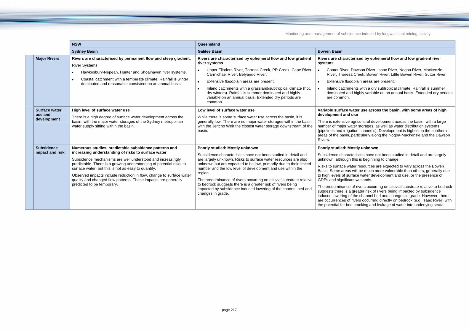
Monitoring and management of subsidence induced by longwall coal mining activity
page 217
NSW Queensland
Sydney Basin Galilee Basin Bowen Basin
Major Rivers Rivers are characterised by permanent flow and steep gradient.
River Systems:
Hawkesbury-Nepean, Hunter and Shoalhaven river systems.
Coastal catchment with a temperate climate. Rainfall is winter dominated and reasonable consistent on an annual basis.
Rivers are characterised by ephemeral flow and low gradient river systems
Upper Flinders River, Torrens Creek, PR Creek, Cape River, Carmichael River, Belyando River.
Extensive floodplain areas are present.
Inland catchments with a grassland/subtropical climate (hot, dry winters). Rainfall is summer dominated and highly variable on an annual basis. Extended dry periods are common.
Rivers are characterised by ephemeral flow and low gradient river systems
Comet River, Dawson River, Isaac River, Nogoa River, Mackenzie River, Theresa Creek, Bowen River, Little Bowen River, Suttor River
Extensive floodplain areas are present.
Inland catchments with a dry subtropical climate. Rainfall is summer dominated and highly variable on an annual basis. Extended dry periods are common.
Surface water use and development
High level of surface water use
There is a high degree of surface water development across the basin, with the major water storages of the Sydney metropolitan water supply sitting within the basin.
Low level of surface water use
While there is some surface water use across the basin, it is generally low. There are no major water storages within the basin, with the Jericho Weir the closest water storage downstream of the basin.
Variable surface water use across the basin, with some areas of high development and use
There is extensive agricultural development across the basin, with a large number of major water storages, as well as water distribution systems (pipelines and irrigation channels). Development is highest in the southern areas of the basin, particularly along the Nogoa-Mackenzie and the Dawson Rivers.
Subsidence impact and risk
Numerous studies, predictable subsidence patterns and increasing understanding of risks to surface water
Subsidence mechanisms are well understood and increasingly predictable. There is a growing understanding of potential risks to surface water, but this is not as easy to quantify.
Observed impacts include reduction in flow, change to surface water quality and changed flow patterns. These impacts are generally predicted to be temporary.
Poorly studied: Mostly unknown
Subsidence characteristics have not been studied in detail and are largely unknown. Risks to surface water resources are also unknown but are expected to be low, primarily due to their limited number and the low level of development and use within the region.
The predominance of rivers occurring on alluvial substrate relative to bedrock suggests there is a greater risk of rivers being impacted by subsidence induced lowering of the channel bed and changes in grade.
Poorly studied: Mostly unknown
Subsidence characteristics have not been studied in detail and are largely unknown, although this is beginning to change.
Risks to surface water resources are expected to vary across the Bowen Basin. Some areas will be much more vulnerable than others, generally due to high levels of surface water development and use, or the presence of GDEs and significant wetlands.
The predominance of rivers occurring on alluvial substrate relative to bedrock suggests there is a greater risk of rivers being impacted by subsidence induced lowering of the channel bed and changes in grade. However, there are occurrences of rivers occurring directly on bedrock (e.g. Isaac River) with the potential for bed cracking and leakage of water into underlying strata

Monitoring and management of subsidence induced by longwall coal mining activity
page 218
7 Knowledge gaps and limitations
Although the knowledge of subsidence impacts resulting from longwall coal mine subsidence in Australia is beginning to build (particularly in NSW), there are still substantial knowledge gaps which inhibit the prevention and amelioration of these impacts. Knowledge gaps and limitations are described below.
7.1 Subsidence mechanisms
7.1.1 Three-dimensional effects
Subsidence is a three-dimensional process, yet because of practical limitations and cost, it is normally measured along survey lines parallel to the long and short sides of the longwall panel, even though the maximum movement may not occur within these planes. In addition to downward movement, it is now known that the subsided overburden moves laterally, towards the centre of the goaf. While vertical subsidence can be predicted with some accuracy, the horizontal component cannot yet be reliably estimated.
7.1.2 Subcritical and supercritical extraction
The subsidence-retarding effects of single panel extraction, as opposed to total subsidence resulting from supercritical extraction of several parallel panels, are recognised. The sudden change in subsidence behaviour when the critical width of extraction is exceeded is commonly observed but has yet to be fully explained. Nevertheless, being able to predict the critical subsidence width can be very important in limiting surface damage and aquifer disruption, while still allowing limited coal extraction to occur.
7.1.3 Near-surface anomalies
Strain and tilt may be particularly affected by near-surface joint dilation, block displacement and partial rotation, since the top few m of the rock mass is only semi-confined. The near-surface zone (down to approximately 15 m depth) of fracturing and jostling contrasts with the tightly confined behaviour of most of the overburden column down to coal seam level. Generally small and localised movements—akin to shrink-swell heaving in expansive soils, but much faster—can be damaging to light surface structures, but cannot be predicted with present methods. Improved prediction might require detection of pre-existing (large) fractures that are preferential features that will open and result in the highly discontinuous strain field that is observed (e.g. using geophysics such as ground penetrating radar).
7.1.4 Overburden bulking factors
In the Sydney Basin the net subsidence typically corresponds to a vertical bulking factor of less than 0.5 per cent (e.g. 2 m of extracted coal at a depth of 200 m results in about 1 m of subsidence). By comparison, the bulking factor for loose-dumped rock fill (analogous to caved debris in a goaf) is about 50 per cent. There also are records of bedding plane separations of 200 mm or more in the subsided overburden column—in other words there are some measurable signs of bulking, though they may be very localised and temporary. Therefore the question arises as to why any subsidence exists at all, since the tendency of a disturbed rock mass is to bulk up. Hence it appears that much of the overburden rock mass remains almost intact and highly compressed during subsidence, indicating that fractures are

Monitoring and management of subsidence induced by longwall coal mining activity
page 219
few, very widely spaced, or extremely tight (or, more likely, a combination of these). This has important implications for the movement of groundwater through a subsided rock mass.
7.1.5 Far-field movements
It was previously thought that that subsidence affected only the footprint of a longwall panel plus a narrow zone, say 100 to 200 m wide, surrounding it. It is now known that small lateral movements—but not vertical movements—are detectable to a distance of 1 to 2 km, on the NSW Southern Coalfield at least. These appear to be related to en masse gravitational movements of the stress-relieved overburden towards nearby gorges and old mine workings. At present these displacements are not known to damage surface structures, though there may be circumstances where this could occur. There is also a question of whether such movements are peculiar to the plateau and gorge topography of the Southern Coalfield, or might be going unrecorded in the Bowen Basin and elsewhere.
7.1.6 Cumulative effects
Small amounts of additional subsidence, in the order of 5 to 10 per cent, are known to be caused by mining of subsequent panels in a side-by-side series. Lateral surface movements above the original panel and towards that being actively mined have also been observed. Neither of these types of movement can be accurately predicted at present. A related issue that has not yet arisen much in Australia is the question of undermining old goafs, although multi-seam mining is likely to become more common in the future. UK experience suggests that remobilisation of old goafs by longwall mining in a lower seam may greatly and unpredictably increase the resulting surface subsidence.
7.2 Impacts on groundwater
7.2.1 Subsidence-enhanced shallow aquifers
The literature is reasonably clear on the negative effects of subsidence on shallow aquifers—interaction with surface water and degradation through chemical reactions—but there are other potentially positive impacts, possibly including increases in the productivity of shallow groundwater systems through increased infiltration (recharge) and increased hydraulic conductivity and storativity in shallow fractured rock aquifers. While these impacts are initially accompanied by a decline in groundwater heads it is expected that there may be long-term improvements in the storage and transmission of water in shallow aquifers above longwall coal mines.
7.2.2 Self-sealing aquitards
Deformation of shale and mudstone beds may be either brittle (crack-generating) or plastic (self-sealing, like putty). Strong shales are assumed to behave in a brittle fashion, but weak shales deform plastically and hence may provide a barrier to downward movement of groundwater. However this behaviour is also affected by stress and moisture content—a tightly confined and moist shale bed may deform plastically even if quite strong. The conditions under which possible self-sealing mechanisms become operative are not currently known.

Monitoring and management of subsidence induced by longwall coal mining activity
page 220
7.3 Impacts on surface water and connected groundwater
7.3.1 Surface water and groundwater interaction
Although several authors allude to the re-appearance downstream of water that has been lost to subsidence induced surface cracking around rivers, there is little data to support this claim. More work is required to investigate the fate of water lost from surface streams to subsidence induced cracking.
7.3.2 Self-healing capacity
Stream bed subsidence cracks may, potentially, seal themselves though accumulation of organic litter, suspended silt, and colloids over time. However the timing, extent and effectiveness of this mechanism have not been demonstrated. Possible acceleration of seal-healing by adding a bentonite (swelling clay) suspension to the water is not yet known.
7.3.3 Degradation of surface water
The creation of new fractures by subsidence exposes fresh rock to reaction with groundwater or infiltrating surface water, and releases salts, acid and iron oxides. The result becomes visible as increased salinity and rust-like discharges from down-gradient springs. Whether the effects of such discharges continue indefinitely, or cease when the fresh rock becomes fully weathered, is not yet known.
7.4 Predictive methods
7.4.1 Empirical techniques for predicting subsidence
The use of empirical techniques is confined to predicting surface and subsurface subsidence above the caving and fracture zones. There are no current empirical techniques for predicting subsurface subsidence in the caving and fracture zones, which is often important for predicting the impact on groundwater resources.
Current empirical techniques generally only predict vertical subsidence despite horizontal movements having significant impacts on surface assets, particularly infrastructure. Prediction of horizontal movements is an area requiring attention.
Empirical techniques being used in Australia are strongly based on NSW Sydney Basin data and conditions, especially those of the Southern Coalfield. A larger database of empirical data is required to provide a greater degree of confidence in the results for different coal environments (in particular, Queensland conditions). However, the accuracy of empirical techniques in Queensland can be improved when the technique is calibrated against local subsidence data from historically mined longwall panels on the same site or adjacent sites.
Most empirical techniques in Australia are designed to over-predict maximum surface subsidence to ensure a conservative approach. However, it should be recognised that the pursuit of conservatism in a model estimate can lead to significant uncertainty in that estimate. In the extreme case an aggressive bias towards conservatism can lead to predictions that are of little value. There has been little discussion between industry and government on the appropriate trade-off between accuracy and conservatism (Section 3.1.1.4).

Monitoring and management of subsidence induced by longwall coal mining activity
page 221
7.4.2 Numerical techniques for predicting subsidence
Current numerical techniques suffer from not being able to adequately simulate anomalous subsidence movements. Although the mechanics of these movements is beginning to be understood, they are not currently incorporated into numerical modelling investigations.
Numerical techniques usually provide output in a series of two-dimensional cross-sections. Three-dimensional outputs are currently beyond the capability of many software packages but are likely to be a future area of development (W Gale 2013, pers. comm.).
7.4.3 Numerical techniques for predicting the impact of subsidence on groundwater
The linking of numerical modelling of subsidence with conventional groundwater modelling to predict the impact on groundwater resources is a key knowledge gap. Although techniques have been developed to determine the change in aquifer hydraulic conductivity from strata subjected to subsidence (e.g. Gale 2008), there are few, published results that illustrate the accuracy of such model predictions. Validation of the modelling approach would be a valuable addition to the literature.
7.4.4 Reporting accuracy and uncertainty
Unlike the groundwater industry, there are no national guidelines for calculating and reporting accuracy and uncertainty in subsidence prediction methods. There is a strong need to maintain consistency in reporting of accuracy and uncertainty to ensure valid comparison across mine sites and methods. A robust method of calculating accuracy needs to be developed, and should be reported along with the measure of conservatism represented by probability of exceedance values.
7.5 Understanding of Queensland coal basins
In contrast to NSW coalfields which have been relatively well studied over the last decade, Queensland’s coal basins amenable to longwall coal mining are relatively poorly understood and require further investigation. There is a general paucity of data and experience on the behaviour and impact of longwall coal mine subsidence in Queensland (particularly in the Galilee Basin but also in the Bowen Basin). In particular, the geotechnical behaviour of the coal measures and overlying formations to longwall caving is poorly understood. Given the valuable groundwater resources in GAB aquifers that overly coal deposits in the western section of the Galilee Basin, and the occurrence of significant wetlands and GDEs in both basins, impact predictions and the subsequent regulatory decisions need to be based on a sound conceptualisation of the regional and local hydrogeology and hydrology.
Given that most knowledge of the impacts of longwall coal mine subsidence has been developed from NSW examples, care needs to be taken in translating this experience to predict the likely subsidence impacts in Queensland. Without local experience to call on, impact predictions in Queensland will inevitably need to draw on the experience gained in NSW. In doing so, the potentially higher uncertainty of prediction should be taken into account when making regulatory decisions. However, over time as there are more examples of Queensland longwall coal mining, there will be less need to rely on NSW experience and uncertainty of prediction may reduce.

Monitoring and management of subsidence induced by longwall coal mining activity
page 222
7.6 Subsidence management
Although minimising subsidence by altering mine layouts has been practised for decades in Australia, there are few examples of other techniques that are often used overseas (particularly in China and India) including:
Backfilling or ‘stowing’ of the mined-out void to support the roof strata. This has been investigated since the 1950s but rejected as too costly in Australia. It is commonly used for subsidence mitigation when mining beneath urban areas in China and India (Lokhande 2005).
Bed separation grouting, which involves injecting grout from surface boreholes into bedding plane cracks that open up ahead of an advancing longwall face. In theory, this could halve subsidence if all larger cracks are successfully filled (Shen et al. 2010).

Monitoring and management of subsidence induced by longwall coal mining activity
page 223
8 Findings and implications
8.1 Subsidence prediction methods
Longwall coal mining is now the most common underground coal mining method in Australia because of its low cost and efficiency in removing coal from deep seams and its good safety record.
The mechanisms for subsidence above longwall coal mining have been well studied and documented in both Australia (mainly NSW) and overseas (mainly the UK and USA) and are summarised in Section 2.3.1.
Empirical techniques are the most commonly used techniques in Australia for predicting surface subsidence due to their ease of use, low cost and because they do not require the complexities of subsidence mechanics to be addressed. However, numerical modelling techniques are favoured over empirical techniques in the following cases:
if the geotechnical conditions are substantially different from those used to develop the empirical techniques
information on changes to groundwater resources in the caving or fracture zone is required.
The most commonly used empirical technique in Australia is the IPM. Consulting company Mine Subsidence Engineering Consultants has developed the IPM using relationships derived from their own database of more than 800 000 subsidence measurements from over 50 collieries in NSW and from four collieries in Queensland. Analysis of the accuracy of the predicted maximum surface subsidence from the IPM against measured values undertaken in this study concluded the following:
The application of the IPM by MSEC is intended to be conservative with predictions being skewed towards an over-estimate of maximum subsidence to reduce the chance that predicted subsidence values will be exceeded. This is reflected in the following probability of exceedance values calculated in this study:
− 15 per cent probability that the predicted maximum subsidence for Bowen Basin, Queensland mines will be exceeded
− 10 per cent probability that the predicted maximum subsidence for mines in NSW will be exceeded.
The accuracy of the IPM for predicting subsidence in the Bowen Basin, Queensland is of similar, if not better, accuracy than for the NSW coalfields despite the empirical relationships upon which it is based being largely determined from NSW examples.
Accuracy of prediction is greatly improved by calibrating the IPM to local subsidence data.
Other empirical techniques used in Australia include:
the Holla NSW Department of Mineral Resources (DMR) method
the Ditton and Frith (2003) method.

Monitoring and management of subsidence induced by longwall coal mining activity
page 224
Much of the analysis of subsidence modelling accuracy relies on quoting probability of exceedance values which, although providing important information on the degree of conservatism, does not indicate the level of uncertainty. In addition to quoting probability of exceedance values, this study recommends that accuracy analyses also provide statistics on the degree of departure from observed results. The Root Mean Squared (RMS) error or the Scaled Root Mean Squared (SRMS) error approach favoured in the Australian groundwater modelling guidelines (Barnett et al. 2012) would also provide an appropriate estimate of the goodness of fit between estimated and measured subsidence.
8.2 Subsidence mechanisms and impact on groundwater and surface water resources
The impact of longwall coal mine subsidence on aquifers and groundwater has largely been developed from theory and from examples in the UK and US (e.g. Singh & Kendorski 1981) enhanced with studies of NSW coal mines (e.g. Forster & Enever 1992). Generalised understandings of the changes of aquifer hydraulic properties and groundwater levels resulting from subsidence associated with longwall coal mines have been developed. These studies suggest that changes in groundwater level and aquifer hydraulic properties differ in the caved zone, fracture zone and surface zone. More recently changes in aquifer hydraulic conductivity can be predicted for single isolated panels from subsidence and rockhead measurements and predictions using a method developed by Gale (2008). Such predictions can be used as inputs to groundwater modelling methods to determine the impact of subsidence on groundwater resources.
Subsidence caused by longwall mining has been found to have impacts on surface water assets including rivers and wetlands and associated ecosystems. Much of the information on the type of impact comes from NSW examples especially in the peat swamp areas of the Sydney Basin. The magnitude of changes in surface and subsurface flows is dependent on the extent to which subsidence changes the structure of the strata overlying the mined coal seams (Frazier et al. 2010; MSEC 2006; Sidle et al. 2000). The level of the impact is dependent on the degree of subsidence, and the substrate, slope, and geomorphology of the surface water environment (Frazier et al. 2010; MSEC 2006; Sidle et al. 2000). The types and ranges of impacts can be divided into impacts on topography, geomorphology, hydrology and ecology. Each one of these impacts is described in detail in Section 2.4.
8.3 Monitoring and measurement methods
Methods to achieve the desired vertical elevation accuracy of around 20 mm required for meaningful analysis of subsidence impacts have historically been confined to traditional ground survey techniques. In recent years, the use of GPS technology has enhanced ground survey techniques allowing quicker and cheaper surveys relative to traditional pegged lines measured with theodolites. In the near term, traditional GPS based ground surveys are likely to remain the dominant method for monitoring longwall coal mine subsidence for single mines due to the relative cost of alternative remote sensing methods.
In areas where mines are clustered and cost sharing options are available, satellite radar technology is already cost-effective and has the necessary vertical accuracy of around 10 to 20 mm. As new satellites are launched and new processing techniques become available, the use of satellite radar technology is likely to become more cost-effective and popular for monitoring mine subsidence.

Monitoring and management of subsidence induced by longwall coal mining activity
page 225
The use of a particular type of satellite radar technology (Interferometric Synthetic Aperture Radar or INSAR) for subsidence measurement is currently being trialled by four coal seam gas explorers in Queensland. The results have not yet been published.
8.4 Generic approach for assessing the impacts of longwall coal mine subsidence
The generic approach described in Section 5 takes a broad risk assessment approach by first identifying and documenting the value of assets at possible risk from mine subsidence, then using predictive techniques to identify the likelihood of impact and determining the risk of impact by combining likelihood and consequence (value) assessment. Finally the approach uses monitoring results to validate the assessment and refine the risk assessment.
The approach tailors the effort depending on the type of assets and the value of the assets at possible risk. Complex and expensive modelling exercises can be avoided if there are no high value water resource assets within the potential area of influence of the mine, or if the assets have a very low risk of being impacted. As such, following this procedure can help the complexity, time, and expense of the investigation to remain commensurate with the economic, social, and environmental value of the assets and level of potential risk.
The approach provides a general guide only on the types of investigation and methods applicable for use in investigating longwall coal mine subsidence. Although elements of the approach have been applied, and are being applied, in Australia, the whole approach needs to be applied, tested and refined before wholesale adoption.
8.5 Conceptual models of Queensland coal deposits amenable to longwall coal mining
Queensland coal deposits amenable to longwall coal mining are restricted to the Bowen and Galilee Basins due to the depth and extent of the economic coal seams. Other basins are more amenable to the more selective bord and pillar methods or the cheaper open cut methods.
In the Bowen Basin, the area of planned and actual longwall coal mining has the potential to impact the Tertiary Basalt and Quaternary Alluvial Aquifers. In most cases, there are significant thicknesses of the low permeability Rewan Formation hydraulically separating the coal measures from overlying units. The effectiveness of this seal has not been field-validated and structural features may enhance preferential flow path through the Rewan Formation. Given that all of the longwall mining developments in the Bowen Basin (historic, current and planned) are well outside the Great Artesian Basin (GAB) boundary, there seems little likelihood of impact of longwall coal mine subsidence on GAB units (including the Clematis Sandstone Aquifer). However, there are isolated outcrops of Clematis Sandstone outside the GAB which could potentially be impacted by longwall coal mining such as in and around the Karborough Range and Kerlong Range north of Coppabella (e.g. near the Ellensfield Mine). These isolated occurrences of Clematis Sandstone Aquifer are not currently used for water supply to any great extent and are hydraulically separated from the main GAB units to the west by significant thicknesses of Permian units. Therefore, any subsidence induced change in these units from longwall coal mining is not likely to impact the GAB or its recharge areas to the west.
In the Galilee Basin, the most significant aquifers are the Mesozoic deposits in the GAB and overlying Eromanga Basin (e.g. Clematis Sandstone, Precipice Sandstone, Hutton

Monitoring and management of subsidence induced by longwall coal mining activity
page 226
Sandstone, Hooray Sandstone and Cadna-Owie Formation). All of the planned longwall coal mines are located to the east of the GAB with the closest mine being the Galilee Coal Mine owned by Waratah Coal. Subsidence modelling suggests that the extent of vertical fracturing induced by the Galilee Coal Mine is likely to be limited to the base of the Rewan Formation and therefore, will have limited impact on the shallower Clematis Sandstone Aquifer (Waratah Coal 2013).
In both the Galilee and Bowen Basins, significant wetlands, watercourses and groundwater dependent ecosystems occur in areas amenable to longwall coal mining. The extent to which these assets are impacted by subsidence is determined by the amount of surface subsidence, tilting and cracking. Although there are some bedrock river channels where stream bed cracking and fracturing of rock bars can occur, most surface water assets are alluvial channels and are susceptible to lowering of the channel bed, changes in grade and ponding in the subsided areas. Ponding in subsided areas is a particular issue identified in a number of recent environmental impact statements (e.g. Carmichael Mine in Galilee Basin (MSEC 2013) and Eagle Downs Mine in the Bowen Basin (DERM 2010).
This study provides detailed analysis of the geotechnical, surface water and groundwater conceptual models of the Galilee and Bowen Basins including a comparison to NSW coal basins. The study shows that there are both similarities and differences in conceptualisation between the Bowen and Galilee Basins in Queensland and the Sydney Basin in NSW and there is a general paucity of data and experience on the behaviour and impact of longwall coal mine subsidence in Queensland (particularly in the Galilee Basin). Therefore, care needs to be taken in translating this experience to predict the likely subsidence impact in Queensland longwall coal mines. Without local experience to call on, predictions of the impact of longwall coal mining in Queensland will inevitably need to draw on the experience gained from NSW. In doing so, the higher uncertainty of prediction should be taken into account when making regulatory decisions. However, over time as there are more examples of Queensland longwall coal mining, there will be less need to rely on the NSW experience and a reduced uncertainty of prediction is expected.
8.6 Management and mitigation of longwall coal mine subsidence
The damaging effects of subsidence are primarily mitigated by modifying mining layouts to protect specific surface structures and water resource assets. Subsidence is primarily minimised by retaining sections of coal to support the overlying strata. This is now supplemented by much more intensive geological investigations, rock mechanic testing and numerical modelling of alternative mining layouts and dimensions.
Due to the relatively high cost and lack of field experience in the local context, other methods to reduce the impact of subsidence have not been generally implemented in Australia but include:
Backfilling or ‘stowing’ of the mined out void to support the roof strata which has been investigated since the 1950s but never actually implemented in Australia. Although backfill stowing has so far been rejected for Australian mines on the grounds of cost, it is commonly used for subsidence mitigation when mining beneath urban areas in China and India (Lokhande 2005).
Bed separation grouting involves injecting grout from surface boreholes into bedding plane cracks that open up ahead of an advancing longwall face which in theory could halve subsidence if all the larger cracks are successfully filled (Shen et al. 2010).

Monitoring and management of subsidence induced by longwall coal mining activity
page 227
In NSW, legislation introduced in 2004 requires all new and existing underground coal mines to have a Subsidence Management Plan prior to commencing any underground mining operations which will potentially lead to subsidence of the land surface. The plans predict potential impacts of underground operations and identify how significant natural and built features are to be managed. In Queensland, there is no formal ‘subsidence management plan’ required but rather subsidence management is incorporated into the Environment Impact Statement or Environmental Management Plan prior to a mining licence being granted and within the Mine Management Plan once the mining licence is granted.

Monitoring and management of subsidence induced by longwall coal mining activity
page 228
9 References
ACARP 2000. The influence of subsidence cracking on longwall extraction. Report by G Klenowski (AMEC) to Australian Coal Association Research Program, report C5016, August 2000.
ACARP 2002. Research into the impacts of mine subsidence on river valleys, cliffs gorges and river systems, with management guidelines. Report by Waddington, A. A and Kay, D. R to Australian Coal Association Research Program report C9067, June 2002.
ACARP 2010, Subsidence control using coal washery waste. Australian Coal Association Research Program report C16023, March 2010.
Adani Mining 2013. Carmichael Coal Mine and Rail Project SEIS. Report for Mine Hydrogeology Report. 13
th Nov 2013. Report prepared by GHD for Adani Mining Pty Ltd.
AGL 2012. Underground water impact report for consultation ATP529P – Galilee Basin. Draft format 28 May 2012.
Anderson, L, Patterson, D and Nicholson, M 2007. Measuring mine subsidence – BHPB Illawarra Coal’s diversified approach. In: Proceedings of the 7
th Conference on Mine Subsidence,
pp. 53‒67.
Anderson, M. P and Woessner, W. W 1992. Applied groundwater modelling, simulation of flow and advective transport, Academic Press, San Diego, USA.
Anonymous 1991. Mitigating losses from land subsidence in the United States. Panel on Land Subsidence. National Research Council. 68p.
ANZECC and ARMCANZ 2000a. Australian and New Zealand Guidelines for fresh and marine water quality 2000. Paper 4, Volume 1, National Water Quality Management Strategy, Australian Government. Australian and New Zealand Environment and Conservation Council and Agriculture and Resource Management Council of Australia and New Zealand. Canberra, Australia.
ANZECC and ARMCANZ 2000b. Australian Guidelines for water quality monitoring and reporting 2000. Document 7 of the National Water Quality Management Strategy, Australian Government. Australian and New Zealand Environment and Conservation Council and Agriculture and Resource Management Council of Australia and New Zealand. Canberra, Australia.
Appleyard, L. D 2001. A review of design guidelines for residential construction in mine subsidence areas of NSW. Proc. of 3
rd Conference on Buildings and Structures Subject to Ground
Movements. Maitland. IE Aust/MSTS. p149-161.
Aquaterra Consulting Pty Ltd 2009a. Narrabri Coal Mine Stage 2 Longwall Project: Hydrogeological assessment. Narrabri Coal Operations Pty Ltd, http://www.whitehavencoal.com.au/operations/documents/67417Part2_GroundwaterReport.pdf. Accessed April 2014.
Aquaterra Consulting Pty Ltd 2009b. An integrated hydrogeological and geotechnical modelling approach to predicting groundwater and surface water impacts of subsidence above longwall mines in the Hunter Valley, International Association of Hydrogeologists, Australian National Chapter, NSW Branch, 2009 Seminar Series.
Aquaveo 1991. Watershed modelling system. Aquaveo, Utah, USA.
Aquaveo 2012. SMS modelling software. Aquaveo, Utah, USA. http://www.aquaveo.com/software/sms-surface-water-modeling-system-introduction. Accessed April 2014.
ARMCANZ and ANZECC 1995. Guidelines for groundwater protection in Australia, National Water Quality Management Strategy, Document 8. Australian Government, Agriculture and

Monitoring and management of subsidence induced by longwall coal mining activity
page 229
Resource Management Council of Australia and New Zealand, and Australian and New Zealand Environment and Conservation Council. Canberra, Australia.
Atkinson, A. A 1902. Working coal under the River Hunter, the Pacific Ocean and its tidal waters near Newcastle NSW. Transactions of the Institution of Mining Engineers, 23, pp. 622–667.
Australian Mining 2008. Australian coal yearbook for 2008. Australian Mining magazine, yearbook series.
Barnett B, Townley L. R, Post V, Evans R. E, Hunt R. J, Peeters L, Richardson S, Werner A. D, Knapton A and Boronkay A 2012. Australian groundwater modelling guidelines, Waterlines report, National Water Commission, Canberra, Australia.
Bauer, R 2008. Planned coal mine subsidence in Illinois: A Public Information Booklet. Circular 573. Illinois Department of Natural Resources and Illinois State Geological Survey.
Bell, F, G, Stacey, T. R and Genske, D. D 2000. Mining subsidence and its effect on the environment: Some differing examples. Environmental Geology, 40 (1‒2) pp. 135‒152.
BMA 2013. Red Hill Mining Lease Environmental Impact Statement – Executive Summary. BHP Billiton Mitsubishi Alliance, December 2013. Via: http://www.dsdip.qld.gov.au/assessments-and-approvals/red-hill-mining-lease-project.html. Accessed February 2015.
BMT WBM 2010. Tuflow GIS Based 2D/1D Hydrodynamic Modelling. BMT WBM, Brisbane, Australia.
Booth, C. J 1986. Strata movement concepts and the hydrogeological impact of underground coal mining Ground Water 24(4), pp. 507‒515.
Booth, C. J, Spande, E. D, Pattee, C. T, Miller, J. D, Bertsch, L. P 1998. Positive and negative impacts of longwall mining on a sandstone aquifer. Environmental Geology, v. 34, no. 2/3, pp. 223‒233.
Booth, C. J 2002. The effects of longwall coal mining on overlying aquifers. In: Younger, P. L and Robins, N. S (editors) Mine water hydrogeology and geochemistry, Geological Society of London, Special Publication 198, pp. 17‒45.
Booth, C.J 2007. Confined-unconfined changes above longwall coal mining due to increases in fracture porosity. Environmental and Engineering Geoscience, v. 13, no. 7, pp. 355‒367.
Boughton, W 2003. Calibrations of the AWBM for use on ungauged catchments – technical report 03/15, CRC for Catchment Hydrology, Canberra, Australia.
Bureau of Meteorology 2013. Atlas of groundwater dependent ecosystems. Via: http://www.Bureau of Meteorology.gov.au/water/groundwater/gde/index.shtml. Accessed November 2014.
Byrnes, R 2003. Case studies in the application of influence functions to visualising surface subsidence, Coal Operators Conference, University of Wollongong & the Australian Institute of Mining and Metallurgy, 2003, pp. 90‒100.
Cao, L, Zhang Y, He, J, Liu, G, Yue, H, Wang, R and Ge, L 2008. Coal mine land subsidence monitoring by using spaceborne InSAR data – a case study in Feng Feng, Hebei Province, China. The International Archives of the Photogrammetry, Remote Sensing and Spatial Information Sciences, Vol. XXXVII. Part B8, Beijing, China.
Centennial Coal 2013. Subsidence management status report 4: monthly update Springvale Colliery March 2013.
Chang, H. C, Ng, A, Zhang, K, Dong, Y, Hu, Z, Ge, L and Rizos, C 2009. Monitoring longwall mine subsidence and far-field displacements using multi-wavelength radar interferometry. In: Proc. of International Conference of the Surveying and Spatial Sciences Institute Conference 2009, Adelaide, Australia, 28 September – 2 October 2009.
Chatfield, C 1996. Model uncertainty and forecast accuracy, Journal of Forecasting, 15, pp. 495‒508.

Monitoring and management of subsidence induced by longwall coal mining activity
page 230
Cheng, M and Colvin, P, 2004. Pipeline stress mitigation for mine subsidence effects, Simpsons Creek, Appin. In: Proc. of the Mine Subsidence Technological Society, 6
th Triennial Conference on
Mine Subsidence, Maitland, 31 October to 2 November 2004.
COAG 2012. National Partnership Agreement on Coal Seam Gas and Large Coal Developments. Council of Australian Governments Agreement between Commonwealth of Australia and States and Territories: NSW, Vic, SA, Qld and NT.
Commonwealth of Australia 1999. Environment Protection and Biodiversity Conservation Act 1999. Via: http://www.comlaw.gov.au/Series/C2004A00485. Accessed April 2014.
Commonwealth of Australia, 2013. EPBC Amendment Bill 2013. July 2013 amendment to the Environment Protection and Biodiversity Conservation Act 1999. Via: http://www.environment.gov.au/epbc/what-is-protected/water-resources. Accessed October 2014.
Commonwealth of Australia 2014. Temperate Highland Peat Swamps on Sandstone: ecological characteristics, sensitivities to change, and monitoring and reporting techniques. Prepared by Jacobs SKM for the Department of the Environment, Commonwealth of Australia.
Coulthard, T 2001. Landscape evolution models: A software review. Hydrological Processes, Vol 15: pp. 165‒173.
Creech, M 1995. A review of subsidence data from the Newcastle Coalfield and a new subsidence prediction method. In: Proc. of the 3
rd Conference on Buildings and Structures Subject to
Ground Movements, Australia, Newcastle. IEAust/MSTS, pp. 199‒208.
CSIRO and SKM 2013. Hydraulic properties of rock types associated with CSG prospective areas – literature review and assessment of current methods to estimate aquifer leakage. A report to the Australian Government Department of Sustainability, Environment, Water, Population and Communities. Commonwealth of Australia.
CSIRO, NCGRT and SKM 2012. Aquifer connectivity within the Great Artesian, Surat, Bowen and Galilee Basins. A report to the Australian Government Department of Sustainability, Environment, Water, Population and Communities. Commonwealth of Australia.
Dawkins, A 2003, Management and rehabilitation of longwall subsidence on streams, lakes and groundwater systems. Proc. of Coal Operators Conference. Wollongong (editor, N Aziz), p117-124.
DEH 2011. The Sydney Basin Bioregion. NSW Department of Environment and Heritage, February 2011. Via: http://www.environment.nsw.gov.au/resources/nature/sydneyBasin.pdf. Accessed January 2014.
DEHP (Department of Environment and Heritage Protection) 2014. WetlandInfo—your first-stop-shop for wetland management resources in Queensland. Via: http://wetlandinfo.ehp.qld.gov.au/wetlands/ Accessed November 2014.
Deltares Systems 2012. DELFT modelling suite. Deltares Systems, Delft, Netherlands.
Department of the Environment 2010. Australian Wetland Database – Directory Wetland Information Sheet. Via: http://www.environment.gov.au/cgi-bin/wetlands/report.pl. Accessed January 2014.
DERM 2009. Queensland water quality guidelines 2009. Department of Environment and Resource Management, Queensland Government, Brisbane, Australia.
DERM 2010. Assessment report under the Environmental Protection Act 1994 Eagle Downs Coal Mine Project proposed by Bowen Central Coal Management Pty Ltd. Department of Environment and Resource Management, Queensland Government, Brisbane, Australia.
Devleeschouwer, X, Declercq, P, Dusar, M and Annekatrien, D 2007. Contrasting ground movements revealed by radar interferometry over abandoned coal mines (Campine, Belgium). Proc. of Fringe 2007, Fruwscatti, Italy.

Monitoring and management of subsidence induced by longwall coal mining activity
page 231
DEW 2006. A Directory of important wetlands in Australia – factsheet. Commonwealth Department of the Environment and Water. Via: http://www.environment.gov.au/resource/directory-important-wetlands-australia-factsheet. Accessed 12 January 2014.
DEWHA 2008. National framework and guidance for describing the ecological character of Australian Ramsar Wetlands Module 2 of the National Guidelines for Ramsar Wetlands—Implementing the Ramsar Convention in Australia. Department of Environment, Water, Heritage and the Arts. Canberra, Australia.
DHI 2012a. MIKE 11, DHI Group, Danish Hydraulics Institute, Denmark.
DHI 2012b. MIKE 21, DHI Group, Danish Hydraulics Institute, Denmark.
DHI 2012c. ECOLAB water quality model, DHI Group, Danish Hydraulics Institute, Denmark.
DHI 2012d. MIKE SHE, DHI Group, Danish Hydraulics Institute, Denmark.
Diersch, H. J. G 2006. FEFLOW Finite element sub-surface flow and transport simulation system reference manual, WASY GmbH Institute for Water Resources Planning and Systems Research.
DIPNR 2002. Hydrological and water quality assessment of the Cataract River 1999‒2002. NSW Department of Infrastructure, Planning and Natural Resources. Sydney, Australia.
Ditton Geotechnical Services 2009. ACARP 2003 empirical prediction subsidence model, Appendix B: Whitehaven Coal Extraction Plan for Narrabri Coal Mine longwall panels 101 to 105 – Subsidence predictions.
Ditton, S.G and Frith, R.C 2003. Review of industry subsidence data in relation to the impact of significant variations in overburden lithology and initial assessment of subsurface fracturing on groundwater. ACARP Project C10023. Strata Engineering Report 00-181-ACR/1.
Ditton, S. G 2011. A new empirical subsidence prediction and geological influence assessment model for the Newcastle Coalfield. In: Proc. of Mine Subsidence Technological Society, 8
th Triennial
Conference, Management of Subsidence: State of the Art. Pokolbin, NSW, Australia. 15‒17 May 2011.
Doherty, J 2005. Model Independent Parameter Estimation (PEST) and uncertainty analysis. Watermark Numerical Computing. Via: http://www.pesthomepage.org/Downloads.php. Accessed June 2014.
Doherty J. E, Hunt R. J and Tonkin M. J 2010. Approaches to highly parameterized inversion: A guide to using PEST for model-parameter and predictive-uncertainty analysis. US Geological Survey Scientific Investigations Report 2010–5211.
Downes B. J, Barmuta L, Fairweather P, Faith D, Keough M, Lake P, Mapstone B, and Quinn G 2002. Monitoring ecological impacts: Concepts and practice in flowing waters. Cambridge University Press, United Kingdom, Cambridge.
Doyle, J. F 1986. Geological setting of Australian coal deposits. Chapter 2 in Martin, C.H (editor) 1986 Australian coal mining practice. AusIMM Monograph 12.
DSEWPaC 2012. Case judgement – compliance and enforcements under the EPBC Act 1999. Department of Sustainability Environment Water Populations and Communities. Via: www.environment.gov.au/epbc/compliance/judgements.html. Accessed March 2013.
DSEWPaC 2013. Implementation of the National Ecological Character Description Framework and Guidance for describing the ecological character of Australia's Ramsar wetlands. Via: http://www.environment.gov.au/water/topics/wetlands/ramsar-convention/implementation-of-framework.html. Accessed January 2014.
DTI 2010. NSW coal industry profile 2010. p 302. NSW Department Trade and Investment, Maitland, NSW, Australia.
Dumpleton, S 2002. Effects of longwall mining in the Selby Coalfield on the piezometry and aquifer properties of the overlying Sherwood Sandstone. In, Younger, P. L and Robins, N. S (editors)

Monitoring and management of subsidence induced by longwall coal mining activity
page 232
Mine water hydrogeology and geochemistry, Geological Society of London Special Publication 198, pp. 75‒88.
Elsworth, D and Liu, J 1995. Topographic influence of longwall mining on groundwater supplies. Ground Water, 33 5, pp. 786‒793.
Engineers Australia 1988. Australian rainfall and runoff Volume 1 and 2, Engineers Australia, Crow’s Nest, NSW, Australia.
Environment Australia 2001. A directory of important wetlands in Australia. Third Edition. Environment Australia, Canberra, Australia.
Esterle, J. S and Sliwa, R 2002. Bowen Basin supermodel 2000. CSIRO Exploration and Mining. Kenmore, Queensland, Australia.
Everett, M, Ross, T and Hunt, G 1998. Final report of the Cataract River Taskforce: Report to Upper Nepean Catchment Management Committee. pp. 76. Picton, NSW, Australia.
eWater 2008. eWater CRC Toolkit. Via: http://www.toolkit.net.au/tools/RRL. Accessed January 2014.
eWater 2009. Source Catchments. eWater Cooperative Research Centre. Canberra, Australia.
eWater 2011a. Guidelines for water management modelling: towards best-practice model application, eWater Cooperative Research Centre, Canberra, Australia.
eWater 2011b. Guidelines for rainfall-runoff modelling: towards best-practice model application, eWater Cooperative Research Centre. Canberra, Australia.
eWater 2012. Guidelines for modelling groundwater surface water interactions. In: Towards best-practice model application. eWater Cooperative Research Centre. Canberra, Australia.
Farmer, I. W 1985. Coal mine structures. pp. 310. Chapman Hall, England, London.
Fensham R. J. Ponder W. F, Fairfax R. J 2010. Recovery plan for the community of native species dependent on natural discharge of groundwater from the Great Artesian Basin. Report to Department of the Environment, Water, Heritage and the Arts, Canberra. Department of Environment and Resource Management, Brisbane, Queensland, Australia.
Forster, I and Enever, J 1992. Hydrogeological response of overburden strata to underground mining, Central Coast NSW. NSW Office of Energy, Sydney, Australia.
Forster, I. R 1995. Impact of underground mining on the hydrogeological regime, Central Coast NSW. In: Sloan S. W and Allman, M. A (Editors), Engineering geology of the Newcastle – Gosford region. Pp.156‒168, Australian Geomechanics Society. Newcastle, NSW, Australia.
Frazier, P, Jenkins, R and Trotter, T 2010. Monitoring the effect of longwall coal mine subsidence on native vegetation and agricultural environments. Ecological Australia. Australian Coal Association Research Program (ACARP) Report C15013.
Gale, W and Sheppard, I 2011. Investigation into abnormal increased subsidence above longwall panels at Tahmoor Colliery NSW. In: Proc. Of the 8
th Triennial Conference on Management of
Subsidence: State of the Art. pp. 63‒80.
Gale, W 2008. Aquifer inflow prediction above longwall panels. SCT Operations, Report prepared for Australian Coal Association Research Program. Report C13013.
Galvin, J. M 1987a. Surface subsidence mechanisms – theory and practice. Part I – Theory. The Coal Journal 16.
Galvin, J. M 1987b. Surface subsidence mechanisms – theory and practice. Part II – Subsidence mechanisms in practice. The Coal Journal 17.
Galvin, J. M 1988. Surface subsidence mechanisms – theory and practice. Part III – Mine design for stability and subsidence control. The Coal Journal 19.

Monitoring and management of subsidence induced by longwall coal mining activity
page 233
Galvin, J. M 2005. A risk study and assessment of the impacts of longwall mining on Waratah Rivulet and surrounds at Metropolitan Colliery. Report to NSW Department of Primary Industries; Galvin and Associates. Report 0504/17-1c.
Ge L, Chang, H-C and Rizos, C 2004. Monitoring ground subsidence due to underground mining using integrated space geodetic techniques. University of NSW, prepared for ACARP Project C11029, 125p. Sydney, Australia.
Ge, L, Chang, H-C and Rizos, C 2007. Mine subsidence monitoring using multi-source satellite SAR images. Photogrammetric Engineering and Remote Sensing, 73(3): pp. 259‒266.
GeoTerra 2010. Tasman Mine Panels 10‒15 subsidence management plan report. Report for Donaldson Coal, Seahampton, NSW, Appendix B.
GHD 2010. Galilee Basin Transmission Line and Substation Project: Corridor selection and preliminary alignment report. Prepared for Powerlink Queensland.
Gilbert and Associates 2009. Bulli Seam Operations – Surface water assessment report for Illawarra Coal Holdings Pty Ltd. Milton, Queensland, Australia.
GlobalSecurity 2013. http://www.globalsecurity.org/military/library/policy/army/fm/6-2/Ch5.htm. Accessed July 2013.
Green, P. M, Carmichael, D. C, Brain, T. J, Murray, C. G, McKellar, J. L, Beeston, J. W, Gray, A. R. G 1997. Lithostratigraphic units in the Bowen and Surat Basins, Queensland. Department of Mines and Energy. Brisbane, Queensland, Australia.
GSQ 2012. Queensland geological mapping polygonised vector digital data. Geological Survey of Queensland. Brisbane, Australia.
Guo, H, Adhikary, D. P, Gaveva, D 2007. Hydrogeological response to longwall mining. CSIRO Exploration and Mining. Prepared for Australian Coal Association Research Program. ACARP Project C14033.
Guo, W, Zou, Y and Liu, Y 2009. Current status and mining subsidence and ground control technology in China. In: Proc. of AusIMM Coal Operators Conference, Wollongong, pp. 140‒145.
Habermehl, M. A 1980. The Great Artesian Basin, Australia. BMR Journal of Geology & Geophys, 5, pp. 9‒38.
Hancock Galilee 2011. Kevin's Corner Environmental Impact Statement: Chapter 11 Surface Water. Hancock Galilee Pty Ltd.
Hansen 2006. Environmental Impact Statement: Ensham Central Project. Ensham Resources, Brisbane, Australia.
Hansen Bailey 2013. Moranbah South Project: Environmental Impact Statement – Chapter 12 Surface Water. Anglo American Metallurgical Coal Pty Ltd.
Harrower, M, Sergeant, P, Shield, S 2010. Subsidence analysis for underground coal mining operations: the use of airborne laser scanning data. In: Proc. of FIG Congress 2010 Facing the Challenges – Building the Capacity. Sydney, Australia. 11‒16 April 2010.
Heath, R. C 1983. Basic groundwater hydrology. US Geological Survey. Water Supply Paper 2220, pp. 84.
Hebblewhite, B, Waddington, A. A and Wood, J. H 2000. Regional horizontal surface displacements due to mining beneath severe surface topography. In: Proc. of 19
th International Conference
on Ground Control in Mining. Morgantown, West Virginia, USA. August 2000.
Hill M. C and Tiedeman, C. R 2007. Effective groundwater model calibration. John Wiley and Sons, Hoboken, New Jersey, USA.
Hinchcliffe, D, Matthew, P, Pillai-McGarry, U, So, H. B and Mulligan, D 2003. Effect of longwall mine subsidence on plant production on cropping land. Report to Australian Coal Association Research Program. ACARP project C8018.

Monitoring and management of subsidence induced by longwall coal mining activity
page 234
Ho, D, Tan, C. W, Grant C. R and Lo, E 2011. Modelling surface infrastructure subject to mining impact. Mine Subsidence Technological Society 8th Triennial Conference, Management of Subsidence: State of the Art. Pokolbin, NSW, Australia. 15‒17 May 2011.
Holla, L 1985. Mining subsidence in NSW 1; Surface subsidence prediction in the Southern Coalfield. Department of Mineral Resources.
Holla, L 1987. Mining subsidence in NSW 2; Surface subsidence prediction in the Newcastle Coalfield. Department of Mineral Resources, NSW, Australia.
Holla, L 1988. Effects of Underground mining on domestic structures – prediction versus performance. In: Proc. of 5
th Australia–New Zealand Conference on Geomechanics. Sydney, Australia.
Holla, L 1991. Mining subsidence in NSW 3; Surface subsidence prediction in the Western Coalfield. Department of Mineral Resources, NSW, Australia.
Holla, L 1997. Ground movement due to longwall mining in high relief areas in NSW. International Journal of Rock Mechanics and Mining Science, 34(5), pp. 775‒787.
Holla, L and Armstrong, M 1986. Measurement of subsurface movement by multi-wire borehole instrumentation. In: Proc. of Australasian Institute of Mine Management 291, pp. 65‒72.
Holla, L and Barclay, E 2000. Mine subsidence on the Southern Coalfield NSW. Department of Mineral Resources, Sydney, NSW, Australia. pp. 118.
HydroGeoLogic 1996. MODHMS/MODFLOW-SURFACT – A comprehensive MODFLOW-based hydrologic modelling system. MODHMS/MODFLOW-SURFACT software documentation, Volume: Groundwater flow modules. HydroGeoLogic, Reston VA 20190.
ICSM 2007. Standards and practices for control surveys (SP1). Version 1.7. Inter-Governmental Committee on Survey and Mapping. Via: http://www.icsm.gov.au/publications/sp1/sp1v1-7.pdf. Accessed July 2013.
ICSM 2011. Digital Elevation Guidelines and Specifications. Via: http://www.icsm.gov.au/elevation/index.html. Accessed July 2013.
ICSM 2013. Surveying for Mapping. Section 4: Surveying using GPS and conclusion. Via: http://www.icsm.gov.au/mapping/surveying4.html. Accessed March 2013
Institution of Engineers Australia 1987. Australian rainfall and runoff, Volume 1 and 2. Institution of Engineers Australia, Crow’s Nest, NSW, Australia.
Innovyse 2012. Infoworks. Innovyse, Wallingford, UK.
ITLIC 2012. Thirlmere lakes inquiry: final report of the Independent Committee. Independent Thirlmere Lakes Inquiry Committee, NSW, Australia.
Jackson, K. S, Horvath, Z. S, Hawkins, P. J 1981. An assessment of the petroleum prospects for the Galilee Basin, Queensland. APPEA Journal 211, pp. 172‒186.
Jankowski, J 2008. Current scientific understanding of longwall mining impact on water quality and quantity. Sydney Catchment Authority, NSW, Australia.
Jankowski, J and Knights, P 2010, Surface Water – Groundwater interaction in the Fractured Sandstone Aquifer Impacted by Mining – Induced Subsidence. Proc. of IAH 2010 Congress, Krakow, Poland. 12-17 September, 2010.
Jankowski, J and Madden, A 2009, The Design of Hydrological and Hydrogeological Monitoring Programs to Assess the Impact of Longwall Mining on Water Resources. IAH NSW Groundwater in the Sydney Basin Symposium, Sydney, NSW, Australia, 4-5 August 2009, W.A.Milne-Home (Ed).
Jareth, S and Huleatt, M 2012. Australian coal resources; 2012 Edition, 1:10,000,000 scale map. Geoscience Australia, Canberra, Australia.
Monitoring and management of subsidence induced by longwall coal mining activity
page 235
JBT 2010. Alpha Coal Project – Groundwater technical report. Hancock Prospecting Pty Ltd: part of Alpha Coal Project Environmental Impact Statement.
Johnson, W and Miller, G. C 1979. Abandoned coal mine lands: Nature, extent and cost of rehabilitation. US Bureau of Mines Special Publication 6-79, 29pp.
Kapp, W. A 1985. Mine subsidence in the Newcastle district, NSW. Transactions of the Institution of Engineers Australia CE27 (4), pp. 331‒340.
Kay, D 1990. Report of the Angus Place subsidence modelling – joint case study. Department of Minerals and Energy, NSW, Australia.
Kay DJ 2012. Managing mine subsidence along railways and highway pavements in the southern coalfield. Journal and News of the Australian Geomechanics Society. 47(1), pp. 33‒52.
Kay, D 2014. Effects of mine subsidence, geology and surface topography on observed valley closure movements and development of an updated valley closure prediction method. Report for ACARP Project C018015.
Kay, D. R, Barbato, J. P and Mills, K. W 2007. Review of mechanisms resulting in observed upsidence and closure movements. In: Proc. of Mine Subsidence Technological Society, 7
th Triennial
Conference. University of Wollongong, NSW, Australia.
Kay, D, Buys, H, Donald, G. S, Howard, M. D and Pells, P. J. N 2011. Management of the Hume Highway pavement for subsidence impacts from longwall mining. Mine Subsidence Technological Society 8
th Triennial Conference, Management of Subsidence: State of the Art.
Pokolbin, NSW, Australia. 15‒17 May 2011.
Kay, D and Carter, J. P 1992. Effects of subsidence on steep topography and cliff lines. In: Proc. of the 11
th International Conference on Ground Control in Mining, Wollongong NSW,
pp. 483‒490.
Kay, D, DeBono, P, and Waddington, A. A 2011. Effects of geology on valley upsidence and closure. In: Proc. of Mine Subsidence Technological Society, 8
th Triennial Conference, Management of
Subsidence: State of the Art. Pokolbin, NSW, Australia. 15‒17 May 2011.
Kay, D, McNabb, K. E and Carter, J. P 1991. Numerical modelling of mine subsidence at Angus Place Colliery. In: Beer, Booker and Carter (editors) Computer methods and advances in geomechanics. Balkema, Rotterdam, pp. 999‒1004.
Kay, D, Whelan, B, Donald, G and Pinkster, H 2007. Monitoring mining induced strain in a road pavement using optical fibres. In: Proc. of Mine Subsidence Technological Society, 7
th
Triennial Conference. University of Wollongong, NSW, Australia. November 2007.
Kellett J. R, Ransley T. R, Coram J, Jaycock J, Barclay D. F, McMahon, G. A, Foster L. M and Hillier J. R 2003. Groundwater recharge in the Great Artesian Basin intake beds, Department of Natural Resources and Mines Technical Report. Department of Natural Resources and Mines, Brisbane, Queensland, Australia.
King, I. P 1987. RMA Model Suite 2, 10, 11. Resource Modelling Associates, Sydney, Australia.
King, I. P 1988. A finite element model for 3 dimensional flow. Resource Modelling Associates report prepared for U.S. Army Corps of Engineers.
Kininmouth, R. J and Baafi, E. Y (editors) 2009. Australasian coal mining practice, 3rd edition. Australasian Institute of Mining and Metallurgy, Monograph 12.
Krogh, M 2007. Management of longwall coal mining impacts in Sydney’s Southern Drinking Water Catchments. Australian Journal of Environmental Management, 14(3), pp.155‒165.
Ladson, A 2008. Hydrology: An Australian introduction. Oxford University Press, Melbourne, Australia.
Linc Energy 2013. Teresa Coal Project: Environmental Impact Statement – Chapter 9 Surface Water. Linc Energy, Brisbane, Australia.
Monitoring and management of subsidence induced by longwall coal mining activity
page 236
Li 2010. A case study on mine subsidence due to multi-seam longwall extraction. In: Proc. of the 2nd
Australasian Ground Control in Mining Conference. Sydney, Australia.
Lokhande, R. D 2005. Subsidence control measures in coal mines: A review. Journal of Scientific and Industrial Research (India), 64, May 2005, p323-332.
Longworth and McKenzie 1983. Report on geotechnical investigation, Area 2, Alpha Queensland. Bridge Oil Limited, Sydney, NSW, Australia.
Lucas, R, Crerar, J, Hardie, R, Merreit, J and Kirsch, B 2009. Isaac River cumulative impact assessment of mining developments. Mining Technology, 118, 3/4, pp. 142‒151.
Marsh, C, Rawsthorn, K, Causebrook, R, Kalinowski, A and Newlands, I 2008. A geological review of the Galilee Basin, Queensland for possible storage of carbon dioxide. Cooperative Research Centre for Greenhouse Gas Technologies, Canberra, Australia, CO2CRC Publication Number RPT08-0983. 91 p.
McDonald, M. G, and Harbaugh, A. W 1983. A modular three-dimensional finite-difference groundwater flow model. Open-File Report 83-875, U.S. Geological Survey. Via: http://pubs.er.usgs.gov/usgspubs/ofr/ofr83875. Accessed June 2014.
McNally, G. H 1996a. New South Wales mining history – the Northern Coalfield. Minfo52, pp. 19‒28. Department of Mineral Resources, NSW, Australia.
McNally, G. H 1996b. Estimation of the geomechanical properties of coal measures rock for numerical modeling. In: Geology and longwall mining (G. H. McNally and C. R. Ward, editors), Coalfield Geology Council of NSW & Conference Publications, pp. 63‒72. Sydney, Australia.
McNally, G. H 1998. Mining geomechanics and the rise and fall of the Cessnock Coalfield. In: Fityus, S. (editor) Geotechnical engineering and engineering geology in the Hunter Valley. pp. 294‒307. Australian Geomechanics Society, Newcastle, Australia.
McNally, G and Evans, R 2007. Impacts of longwall mining on surface water and groundwater, Southern Coalfield NSW. Report prepared for NSW Department of Environment and Climate Change, eWater Cooperative Research Centre, Canberra, Australia.
McNally, G. H and Ward, C. R 1996. (editors) Symposium on geology in longwall mining. Conference Books, Springwood, pp. 269‒272.
McNally, G. H, Willey, P. L and Creech, M 1996. Geological factors influencing longwall-induced subsidence. In: Geology and longwall mining (G. H McNally and C. R Ward, editors) Coalfield Geology Council of NSW & Conference Publications, pp. 257‒268. Sydney, Australia.
METServe 2012. South Galilee Coal Project Environmental Impact Statement. Via: http://www.southgalilee.com.au/SGCPEIS.aspx. Accessed November 2014.
Mills, K. W 2004. Mitigation of subsidence impacts at Marhnyes Hole rockbar. Proc. of the 6th
Conference on Buildings and Structures Subject to Ground Movements. Maitland. IE Aust/MSTS, p41-46.
Mills, K. W 2009. Subsidence engineering, Chapter 37. In Kininmouth, R. J and Baafi, E. Y (editors) Australasian Coal Mining Practice, third edition, Australasian Institute of Mining and Metallurgy, Monograph 12, pp. 874‒902.
Mills, K. W 2011. Developments in understanding subsidence with improved monitoring. Proc. of the 8
th Conference on Mine Subsidence, pp. 25‒41.
Mitchell, G.W 2009. Longwall mining. In: Kininmouth, R. J and Baafi, E. Y (editors) 2009. Australasian coal mining practice. 3rd edition. Australasian Institute of Mining and Metallurgy, Monograph 12, pp. 340‒375.
Moebs, N. M and Barton, T. M 1985. Short-term effects of longwall mining on shallow water sources. US Bureau of Mines Information Circular IC 9042, pp. 13‒24.
Moya, C 2011. Hydrostratigraphic and hydrochemical characterisation of aquifers, aquitards and coal seams in the Galilee and Eromanga Basins, Central Queensland, Australia. Confirmation of

Monitoring and management of subsidence induced by longwall coal mining activity
page 237
Candidature report including literature review for Doctor of Philosophy. Queensland University of Technology, Brisbane, Australia.
MSB (no date). Chain Valley Bay restoration project: special report [on works completed 1986-1990]. NSW Mine Subsidence Board, Newcastle, Australia.
MSEC 2003. Tahmoor North longwall panels 22 & 23; Report on the Prediction of Subsidence Parameters and the Assessment of Subsidence Impacts on Natural Features and Surface Infrastructure in support of a Section 138 Application. Mine Subsidence Engineering Consultants unpublished report to NSW DTIRIS No. WKA137.
MSEC 2004. BHP Billiton, Illawarra Coal, Appin Colliery Longwalls 701 to 704; Report on Anomalous Subsidence Movements in the Southern Coalfield. Mine Subsidence Engineering Consultants Report MSEC188 (confidential report).
MSEC 2006. Impacts of longwall mining to rivers and cliffs in the Southern Coalfield. In: Proceedings of Coal 2006: Coal Operators Conference, University of Wollongong and AusIMM, pp. 327‒336.
MSEC 2007a. Introduction to longwall mining and subsidence. Report by Mine Subsidence Engineering Consultants, Chatswood, NSW, Australia, http://www.minesubsidence.com/index_files/files/Intro_Longwall_Mining_and_Subs.pdf.
MSEC 2007b. General Discussion on systematic and non systematic mine subsidence ground movements. Mine Subsidence Engineering Consultants. Via: http://www.minesubsidence.com/index_files/files/General_Disc_Mine_Subs_Ground_Mvmnts.pdf. Accessed October 2013.
MSEC 2008. Methods of subsidence prediction. Unpublished report by Mine Subsidence Engineering Consultants, Chatswood, NSW, Australia.
MSEC 2009. Subsidence impact assessments to support the BHP Billiton Illawarra Coal Part 3A Development application for Bulli Seam Operations. Mine Subsidence Engineering Consultants Report 404 Rev D. Mine Subsidence Engineering Consultants, Chatswood, NSW, Australia.
MSEC 2010, BHP Billiton, Illawarra Coal, Bulli Seam Operations, Subsidence assessment report. Mine Subsidence Engineering Consultants Report MSEC456 Revision B, to support the EIS for submission to DSEWPAC. Mine Subsidence Engineering Consultants, Chatswood, NSW, Australia.
MSEC 2013. Carmichael Project: Revised subsidence assessment, in support of the Environmental Impact Statement. Prepared for Adani Mining Pty Ltd. Mine Subsidence Engineering Consultants, Chatswood, NSW, Australia.
MSEC 2014. Review of the Incremental Profile Method—review of the accuracy of vertical subsidence predictions obtained using the Incremental Profile Method of prediction for longwall mining in Queensland and NSW. MSEC Report to SKM. MSEC Report Number MSEC654, Rev B. Mine Subsidence Engineering Consultants, Chatswood, NSW, Australia.
Muir, K 2010. The impacts of coal mining on the Gardens of Stone. The Colong Foundation for Wilderness, Sydney, Australia.
NCB 1966. Subsidence engineers’ handbook. 1st edition. National Coal Board, Mining Department, London, UK.
NCB 1975. Subsidence engineers’ handbook, 2nd edition. National Coal Board, Mining Department,
London, UK.
Nicholls, B 2001. How NSW and Queensland coalfields differ – what we need to do better. Proc. of Coal Operators Conference, Geotechnology Colloquium. AusIMM Illawarra Branch. Wollongong, NSW, Australia. February 2001, pp. 25‒33.
NSW DMR 2003. Guideline for applications for subsidence management approvals. NSW Department of Mineral Resources, Sydney, Australia.

Monitoring and management of subsidence induced by longwall coal mining activity
page 238
NSW DoP 2008. The impacts of underground coal mining on natural features in the Southern Coalfield – Strategic Review. NSW Department of Planning, Sydney, Australia.
NSW DTIRE 2014. Sydney Basin – Geological overview. NSW Department of Trade, Investment, Resources and Energy. Via: http://www.resources.nsw.gov.au/geological/overview/regional/sedimentary-basins/sydbasin. Accessed January 2014.
DTIRE 2015. NSW Department of Trade, Investment, Resources and Energy. Via: http://www.resourcesandenergy.nsw.gov.au/miners-and-explorers/applications-and-approvals/environmental-assessment/subsidence-management. Accessed February 2014.
NSW Office of Water 2012. Georges catchment. NSW Department of Primary Industries, Office of Water. Via: http://www.water.nsw.gov.au/Water-management/Basins-and-catchments/Georges-catchment/Georges-catchment/default.aspx. Accessed January 2014.
NSW Office of Water 2013. Hawkesbury-Nepean catchment. NSW Department of Primary Industries, Office of Water. Via: http://www.water.nsw.gov.au/Water-management/Basins-and-catchments/Hawkesbury-catchment/Hawkesbury-catchment/default.aspx. Accessed January 2014.
NSW PAC 2009. The Metropolitan Coal Project review report. NSW Planning and Assessment Commission, Sydney, Australia.
NSW PAC 2010. Wallarah 2 Coal project. PAC report, NSW Planning and Assessment Commission, Sydney, Australia.
NSW Scientific Committee 2005. Alteration of habitat following subsidence due to longwall mining – key threatening process listing. Via: http://www.environment.nsw.gov.au/determinations/LongwallMiningKtp.htm. Accessed February 2014.
NUDLC 2012. Minimum Construction Requirements for Water Bores in Australia. Feb 2012. 3rd Edition. National Uniform Drillers Licensing Committee publication
NWC 2012. Hydrological modelling practices for estimating low flows—guidelines. Barma, D and Varley, I. National Water Commission, Canberra, Australia.
Parsons Brinckerhoff, 2007. Collaborative research program: impacts of longwall mining in the Waratah Rivulet – literature review on longwall mining. Prepared for the Sydney Catchment Authority, Sydney, Australia.
Peabody 2014. North Goonyella Mine. Via: http://www.peabodyenergy.com/content/412/Australia-Mining/Queensland/North-Goonyella-Mine. Accessed June 2014.
Pells Consulting 2011. Report on the water levels of the Thirlmere Lakes. Pells Consulting Report P053.R1. pp. 103. MacMasters Beach, NSW, Australia.
Pells Consulting 2012. Memorandum: Thirlmere Lakes addendum 4 to report of October 2011. Pells Consulting Report P053.M13. MacMasters Beach, NSW, Australia.
Peng, S. S 1986. Coal mine ground control, 2nd edition, Wiley Interscience. New York.
Peng, S. S and Chiang, H. S 1984. Longwall mining. Wiley Interscience. New York.
Pennsylvania DEP 2010. Ryerson Station State Park – Ryerson Station Dam – Damage Claim Number SA1736. Pennsylvania Department of Environmental Protection (DEP), California District Office, US.
PEST 2015. Model-independent parameter estimateion and uncertainty analysis. Via: http://www.pesthomepage.org. Accessed Feb 2015.
Petts, G. E 1987. Timescales for ecological change in regulated rivers. In: Regulated streams. Craig, J.F and Kemper, J.B (editors) pp. 257‒266, New York.

Monitoring and management of subsidence induced by longwall coal mining activity
page 239
Pidgeon, A. R, Barber, R. E, Christie D, Kay D. J, Robinson, G. K, Sheppard, I. C and Sweeting R. D 2011. Management of the Main Southern Railway for subsidence impacts from longwall mining. In: Proc. of Mine Subsidence Technological Society, 8
th Triennial Conference,
Management of Subsidence: State of the Art, Pokolbin, NSW. 15‒17 May 2011.
Piper, A. M 1953. A graphic procedure in the geochemical interpretation of water analysis. United States Geological Survey, Washington D.C.
QDEEDI 2012. Queensland coal measures – spatial data set. Queensland Department of Employment, Economic Development and Innovation.
QDNRM 2012a. Queensland’s coal mines and advanced projects. Queensland Department of Natural Resources and Mines. Via: http://mines.industry.qld.gov.au/assets/coal-pdf/new_coal_min_adv_proj.pdf. Accessed July 2012.
QDNRM 2012b. Ordered drainage 100K – Queensland – digital data for download. Queensland Department of Natural Resources and Mines. Via: http://www.nrm.qld.gov.au/services_resources/item_details.php?item_id=34451. Accessed March 2013.
QDNRM 2012c. Dams and weirs location – Queensland – digital data for download. Queensland Department of Natural Resources and Mines. Via: http://www.nrm.qld.gov.au/services_resources/item_details.php?item_id=34514. Accessed March 2013.
QDNRM 2012d. Groundwater database. Queensland Department of Natural Resources and Mines, Brisbane, Australia.
QDNRM 2012e. Great Artesian Basin resource operations plan February 2007 Amended November 2012. Queensland Department of Natural Resources and Mines, Brisbane, Australia.
QDNRM 2013. Fitzroy Basin resource operations plan January 2004 Amended December 2013 Revision 4. Queensland Department of Natural Resources and Mines, Brisbane, Australia.
QDNRM 2014a. Comments on Milestone 6 – Conceptual models of Queensland coalfields amenable to longwall coal mining. Queensland Department of Natural Resources and Mines. Compiled by Bleakley, A and Larsen, D.
QDNRM 2014b. Groundwater systems in the Eastern Galilee Basin: draft background paper. Queensland Department of Natural Resources and Mines (permission sought from Bleakley, A. to cite in this report).
QDSDIP 2014a. Queensland Department of State Development, Infrastructure and Planning. Via: http://www.dsdip.qld.gov.au/assessments-and-approvals/coordinated-projects.html. Accessed November 2013.
QDSDIP 2014b. Carmichael Coal Mine and Rail project: Coordinator-General’s evaluation report on the environmental impact statement. Department of State Development, Infrastructure and Planning, Brisbane, Australia.
QEHP 2005. A Directory of important wetlands in australia. Queensland Department of Environment and Heritage Protection. Via: http://dds.information.qld.gov.au/DDS/Search.aspx?title="Wetlandsdirectoryofimportant". Accessed November 2013.
QEHP 2013. Wetland systems, WetlandInfo, 22/03/2013. Queensland Department of Environment and Heritage Protection. Via: http://wetlandinfo.ehp.qld.gov.au/wetlands/what-are-wetlands/definitions-classification/system-definitions.html. Accessed January 2014.
QWC 2012, Hydrogeology of the Surat Cumulative Management Area. Queensland Water Commission, Brisbane, Queensland.
Queensland Government 1989. Mineral Resources Act 1989. Via: https://www.legislation.qld.gov.au/LEGISLTN/CURRENT/M/Mineral ReA89.pdf Accessed April 2014.

Monitoring and management of subsidence induced by longwall coal mining activity
page 240
Queensland Government 1994. Environment Protection Act 1994. Via: https://www.legislation.qld.gov.au/LEGISLTN/CURRENT/E/EnvProtA94.pdf. Accessed April 2014.
Queensland Government 2006. Water Resource (Great Artesian Basin) Plan 2006.
Queensland Government 2011. Water Resource Fitzroy Basin Plan 2011. Queensland Department of Natural Resources and Mines, Brisbane, Australia.
Queensland Government 2013. Mineral Resources Regulations (2013). Via: https://www.legislation.qld.gov.au/LEGISLTN/CURRENT/M/MineralReR13.pdf. Accessed April 2014.
Ramsar Convention 1999. Resolution VII.10. Wetland risk assessment framework. Secretariat of the Ramsar Convention, Gland, Switzerland.
Raucoules, D, Colesanti, C and Carnec, C 2007. Use of SAR interferometry for detecting and assessing ground subsidence. C.R. Geoscience 339(2007): pp. 289‒302.
Reid, P 1995. Controlled mining under Cataract Reservoir. Proc. of the 3rd
Mine Subsidence Technology Society Conference, Newcastle, Australia, pp. 179‒187.
Reid, P 1996. Effect of mining on permeability of rock strata on the Southern Coalfield. In: McNally G.H and Ward C.R (editors). Symposium on geology in longwall mining. Conference Books, Springwood, pp. 273–280.
Retallack, G. J, Sheldon, N. D, Carr, P. F, Fanning, M, Thompson, C. A, Williams, M. L, Jones, B. J and Hutton, A 2011. Multiple early Triassic greenhouse crises impeded recovery from Late Permian mass extinction. Palaeogeography, Palaeoclimatology, Palaeoecology. Vol 308, Issues 1‒2, pp. 233‒251.
Reynolds, R. G 1977. Coal mining under stored waters. Report of an inquiry by Justice R. G Reynolds to the NSW Government on coal mining under stored waters of Nepean, Avon, Cordeaux, Cataract and Woronora Reservoirs, NSW. Sydney, Australia.
Riley, S, Finlayson, M, Gore, D, McLean, W and Thomas, K 2012. Thirlmere Lakes Inquiry: draft report. NSW Department of Environment and Heritage. Via: http://www.environment.nsw.gov.au/resources/water/Thirlmerelakesdraftreport.pdf. Accessed February 2015.
Rogers, S, McGregor, G, Takahashi, E, Shaw, M, and McNeil, V 2011. Stream ecosystem health response to coal seam gas water release: salinity guidelines. Queensland Department of Environment and Resources Management, Brisbane, Australia.
RPS 2012. Galilee Basin; Report on hydrogeological investigations. RPS Australia East Pty Ltd report prepared for Resource and Land Management Services Pty Ltd, Brisbane, Australia.
SCA 2006. Groundwater investigations for drought water supply: technical overview report. Sydney Catchment Authority, Sydney, Australia.
Schlumberger Water Services 2012. Namoi Catchment water study. Prepared for the Department of Trade and Investment, Regional Infrastructure and Services, NSW. Report 50371/P4-R2 FINAL. Sydney, Australia.
Scott, S, Beeston, J and Carr, A 1995. Galilee Basin, pp. 341‒352. Geological Society of Australia-Coal Geology Group, Brisbane, Australia.
Seedsman, R and Dawkins, A 2006. Techniques to predict and measure subsidence and its impact on the groundwater regime above shallow longwall panels: Final report March 2006. ACARP Project 13009 pp. 17‒18, 50‒57, and 89.
Seedsman Geotechnics 2012. South Galilee Coal Project: Environmental Impact Statement – Appendix H, Life of Mine Subsidence Deformations. Prepared for Metserve Pty Ltd, Brisbane, Australia.

Monitoring and management of subsidence induced by longwall coal mining activity
page 241
Shen, B, Alehossein, H, Poulsen, B and Waddington, A 2010. Subsidence control using coal washery waste. CSIRO and MSEC, prepared for Australian Coal Association Research Program report C16023.
Sidle, R. C, Kamil, I, Sharma, A and S Yamashita 2000. Stream response to subsidence from underground coal mining in central Utah. Environmental Geology 393/4: pp. 279‒291.
Simon, A and Castro, J 2003. Measurement and analysis of alluvial channel form. In: Kondolf, H. M and H. Piegey (editors) Tools in fluvial geomorphology. pp. 291‒322. Wiley, New York.
Singh, M. M and Kendorski F. S 1981. Strata disturbance prediction for mining beneath surface water and waste impoundments. In: Proc. of the 1
st Conference in Ground Control in Mining,
Morgantown, West Virginia, July 1981, pp. 76‒88.
Singh, R. N and Jakeman, M 2001. Strata monitoring investigations around longwall panels beneath the Cataract Reservoir. Mine Water and the Environment 20, pp. 55‒64.
SKM 2009a. Isaac Connors Groundwater Project. Part A: Conceptual model for groundwater. Report for the Fitzroy Basin Water Resource Plan Amendment to the Queensland Government. Brisbane, Australia.
SKM 2009b. Isaac Connors Groundwater Project. Part B: Assessment of groundwater dependent ecosystems. Report for the Fitzroy Basin Water Resource Plan Amendment to the Queensland Government. Brisbane, Australia.
SKM 2009c. Galilee Coal Project Groundwater Impact Assessment – Galilee Basin. Unpublished report for Waratah Coal Inc.
SKM 2011. Wards Well Groundwater Modelling Stage 1 Completion Report. BHP Mitsui Coal BMC.
Spreckels, V 2000. Monitoring of coal mine subsidence by HRSC-A DATA. International Archives of Photogrammetry and Remote Sensing. Vol. XXXIII, Part B7, Amsterdam.
Standards Australia 1993. Geotechnical site investigations. Homebush, NSW.
Standards Australia 2009. Australian Standards (AS/NZS ISO 31000:2009) Risk management – Principles and guidelines. Homebush, Australia.
Sundaram, B, Feitz, A, de Caritat, P, Plazinska, A, Brodie, R, Coram, J and Ransley, T 2009. Groundwater sampling and analysis – a field guide. Geoscience Australia, Record 2009/27, 95 pp.
SunWater 2012. Nathan Dam and pipeline project environmental impact statement – Chapter 14: Surface Water. SunWater, Brisbane, Australia.
Swarbrick, G and Pinkster, H 2011. Mitigation of subsidence impacts on the Upper Canal, Mine Subsidence Technological Society. In: Proc. of the 8
th Triennial Conference, Management of
Subsidence: State of the Art, Pokolbin, Australia. 15‒17 May 2011.
Sydney Morning Herald 2005. Article on Sydney Catchment Authority expenditure on preventing mining related damage. 28 Feb 2005.
Tahmoor Coal 2013. Via: http://tahmoorcoal.com.au/EN/Pages/TahmoorHome.aspx. Accessed April 2013.
Theis, C. V 1935. The relation between the lowering of the piezometric surface and the rate and duration of discharge of a well using groundwater storage. Am. Geophys. Union Trans., vol. 16, pp. 519‒524.
Total Environment Centre 2007. Impacts of longwall coal mining on the environment of NSW. Total Environment Centre, Sydney, Australia.
Ulan Coal 1998. Ulan Highwall Project. In: Aziz, N (editor) Coal 1998: Coal Operators' Conference. University of Wollongong and the Australasian Institute of Mining and Metallurgy, 325‒332.

Monitoring and management of subsidence induced by longwall coal mining activity
page 242
URS 2010a. Ellensfield Coal Mine Project Environmental Impact Statement. URS Australia, Brisbane, Australia.
URS 2010b. Alpha Coal Project Environmental Impact Statement. Via: http://gvkhancockcoal.com/publications/24-environmental-impact-statements/99-alpha-coal-project-eis-2010. Accessed September 2013.
URS 2012a. Kevin’s Corner Project Supplementary Environmental Impact Statement Interim Subsidence Management Plan, URS Australia, Brisbane, Australia.
URS 2012b. Groundwater Impact Assessment Bowen Gas Project. URS Australia for Arrow Energy, Brisbane, Australia.
US Army Corps Engineers 1992. HEC HMS, US Army Corps Engineers, Washington DC.
US Army Corps Engineers 1995. HEC RAS River Analysis System, US Army Corps Engineers, Washington DC.
US EPA 1971. Stormwater management model. US Environment Protection Authority, Ohio USA.
US EPA 1983. Water Quality Analysis Simulation Program. US EPA Water Quality Technical Support Centre, Athens, GA, USA.
US EPA 1987. Qual2K – Framework for simulating river and stream water quality, Civil and Environmental Engineering Department, Tufts University, Medford, USA.
US EPA 2005. Watershed Analysis Risk Management Framework (WARMF). US EPA Ecosystems Research, Athens, GA, USA.
US EPA 2009. Guidance on the development, evaluation and application of environmental models. US EPA Office of the Science Regulator, Council for Regulatory Environmental Modelling, Washington DC, USA.
USGS 1999. UCODE. International Ground Water Modelling Centre of the Colorado School of Mines and U.S. Geological Survey, Colorado, USA.
USGS 2008. GSFLOW. US Geological Survey, Reston, VA, USA.
USGS 2012. PHREEQC. US Geological Survey, Reston, VA, USA.
Vergara, M, Landon-Jones, I, Pinkster, H and McGill, M 2011. Protection of Upper Canal against impact of underground mining – the LW409 experience. In: Proc. of the Mine Subsidence Technological Society, 8
th Triennial Conference, Management of Subsidence: State of the Art,
Pokolbin, Australia. 15‒17 May 2011.
Victorian EPA 2003. State Environment Protection Policy (Waters of Victoria). Victorian Government Gazette S 107:1‒52.
Victorian EPA 2009, Sampling and analysis of waters, wastewaters, soils and wastes. Victoria EPA, Victorian Government, Australia, Melbourne.
Waddington, A. A 2006. The impacts of coal mine subsidence on streams, river valleys and gorges. Invited paper by the Dutch Association for Engineering Geology, for publication in the Ingeokring Newsletter on Subsidence, Vol. 13 No. 1, 2006, pp. 33‒37.
Waddington, A. A and Kay, D. R 1995. The Incremental Profile Method for the prediction of subsidence, tilt, curvature and strain over a series of panels. In: Proc. of the Mine Subsidence Technological Society, 3
rd Triennial Conference on Buildings and Structures Subject to
Ground Movement. Newcastle, Australia. February 1995.
Waddington, A. A and Kay, D. R 1998a. Development of the Incremental Profile Method of predicting subsidence and its application in the Newcastle Coalfield. In: Proc. of the Mine Subsidence Technological Society, 4
th Triennial Conference on Buildings and Structures Subject to
Ground Movement. Newcastle, Australia. July 1998.

Monitoring and management of subsidence induced by longwall coal mining activity
page 243
Waddington, A. A and Kay, D. R 1998b. Recent development in the Incremental Profile Method of predicting subsidence, tilt and strain over a series of longwall panels. In: Proc. of the International Conference on Geomechanics and Ground Control in Mining and Underground Construction. Wollongong, Australia. July 1998.
Waddington, A. A and Kay, D. R 2001. Comparisons of predicted and observed mine subsidence profiles. In: Proc. of the Mine Subsidence Technological Society, 5
th Triennial Conference,
Coal Mine Subsidence 2001 – Current Practice and Issues. Maitland, Australia. August 2001.
Waddington, A. A, and Kay, D. R 2002a. ACARP management information handbook on the undermining of cliffs, gorges and river systems Version 1. Developed from ACARP Research Projects C8005 and C9067.
Waddington, A. A and Kay, D. R 2002b. Research into the impacts of mine subsidence on the strata and hydrology of river valleys and development of management guidelines for undermining cliffs, gorges and river systems. Final report of ACARP Research Project C9067.
Waddington, A. A and Kay, D. R 2003. The impacts of subsidence on creeks, river valleys and gorges. In: Proc. of the 4
th Underground Coal Operators Conference – The Longwall Environment.
University of Wollongong, Australia. February 2003.
Waddington, A. A, Barbato, J. P, Bullock, D. W, Kay, D. J, 2011. The assessment of subsidence impacts on building structures. In: Proc. of the Mine Subsidence Technological Society, 8
th
Triennial Conference, Management of Subsidence: State of the Art, Pokolbin, Australia. 15‒17 May 2011.
Wagner and Schumann 1991. Surface effects of total coal-seam extraction by underground mining methods. J.S. Afr. Inst. Min. Metal. 91(7) pp. 221‒231.
Waltham, A. C 1989. Ground subsidence. Blackie, Glasgow, UK. pp 202.
Waratah Coal 2013. Galilee Coal Project: Supplementary Environmental Impact Statement – Longwall mining subsidence report. Waratah Coal, Brisbane, Australia.
Whittaker, B. N and Breeds, C. D 1977. The influence of surface geology on the character of mining subsidence. In: Proc. of the International Symposium on Geotechnics of structurally complex formations. Capri, Italy. pp. 459‒468.
Whittaker, B. N and Reddish, D. J 1989. Subsidence: occurrence, prediction and control. Elsevier. California, USA.
Whittaker, B. N, Singh, R. N and Neate, C. J 1979. Effect of longwall mining on ground permeability and subsurface drainage. In: Argall, G. O (editor) Mine drainage, Proc. of the International Mine Drainage Symposium, Denver CO, USA. pp.161‒183.
Willey P. L 1993. Improved methods of subsidence engineering. National Energy Research, Development and Demonstration Council end of project report No 1311. Australian Coal Industries Research Laboratories, North Ryde, Australia.
Willgoose, G 2005. User manual for SIBERIA (Version 8.30). Telluric Research, Scone, Australia.
Worley Parsons 2013. Groundwater risks associated with coal seam gas development in the Surat and southern Bowen Basins. Prepared for Queensland Department of Natural Resources and Mines, Brisbane, Australia.
Wu, J, Zhang, L and Li, T 2011. Monitoring ground subsidence in Shanghai Maglev area using PALSAR and ASAR data. In: Proc. of the Joint International Symposium on Deformation Monitoring. Hong Kong, China, 2‒4 November 2011.

Monitoring and management of subsidence induced by longwall coal mining activity
page 244
Appendix A: MSEC report on the accuracy of the Incremental Profile Method
Double click on the document cover to open.
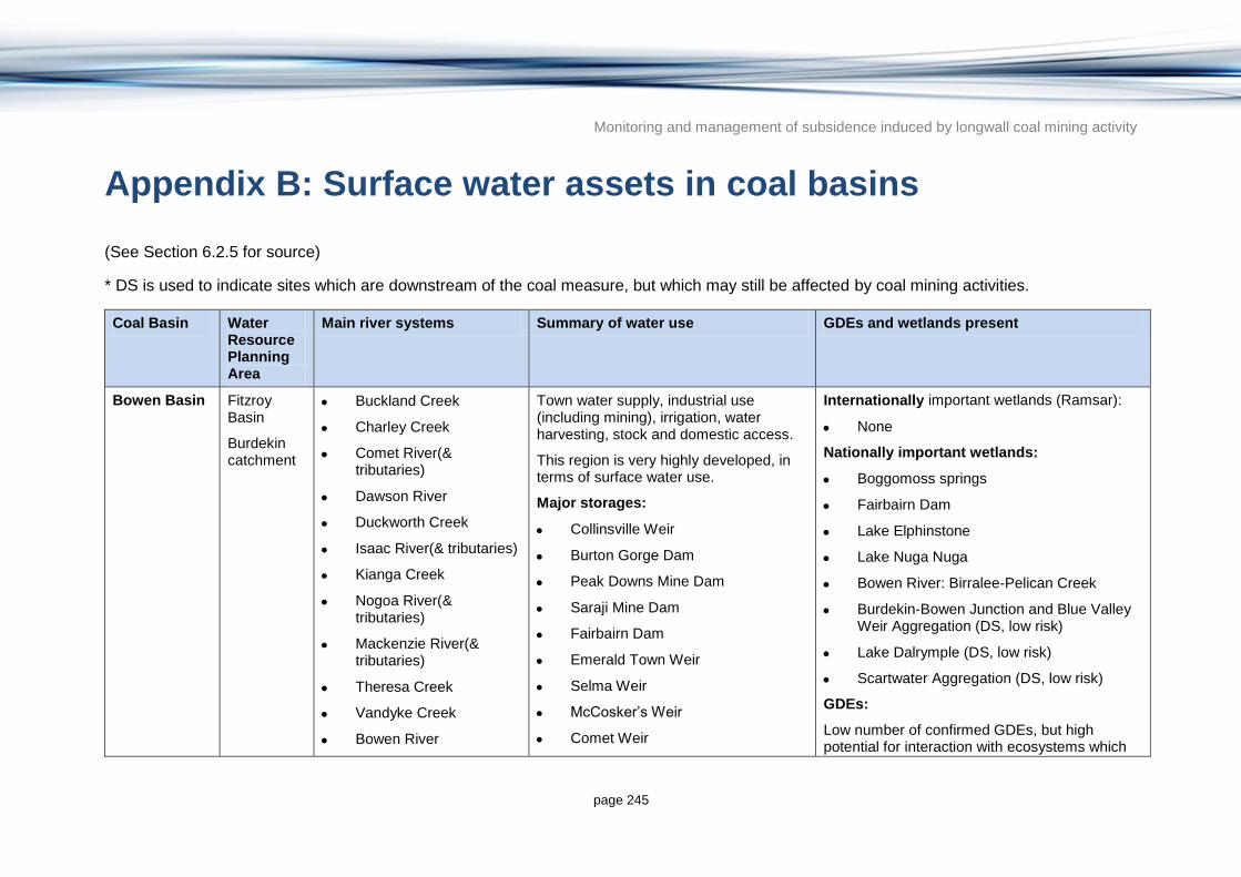
Monitoring and management of subsidence induced by longwall coal mining activity
page 245
Appendix B: Surface water assets in coal basins
(See Section 6.2.5 for source)
* DS is used to indicate sites which are downstream of the coal measure, but which may still be affected by coal mining activities.
Coal Basin Water Resource Planning Area
Main river systems Summary of water use GDEs and wetlands present
Bowen Basin Fitzroy Basin
Burdekin catchment
Buckland Creek
Charley Creek
Comet River(& tributaries)
Dawson River
Duckworth Creek
Isaac River(& tributaries)
Kianga Creek
Nogoa River(& tributaries)
Mackenzie River(& tributaries)
Theresa Creek
Vandyke Creek
Bowen River
Town water supply, industrial use (including mining), irrigation, water harvesting, stock and domestic access.
This region is very highly developed, in terms of surface water use.
Major storages:
Collinsville Weir
Burton Gorge Dam
Peak Downs Mine Dam
Saraji Mine Dam
Fairbairn Dam
Emerald Town Weir
Selma Weir
McCosker’s Weir
Comet Weir
Internationally important wetlands (Ramsar):
None
Nationally important wetlands:
Boggomoss springs
Fairbairn Dam
Lake Elphinstone
Lake Nuga Nuga
Bowen River: Birralee-Pelican Creek
Burdekin-Bowen Junction and Blue Valley Weir Aggregation (DS, low risk)
Lake Dalrymple (DS, low risk)
Scartwater Aggregation (DS, low risk)
GDEs:
Low number of confirmed GDEs, but high potential for interaction with ecosystems which

Monitoring and management of subsidence induced by longwall coal mining activity
page 246
Coal Basin Water Resource Planning Area
Main river systems Summary of water use GDEs and wetlands present
Kangaroo Creek
Little Bowen River
Pelican Creek
Suttor Creek
Suttor River
Potential impact to the Fitzroy River (downstream).
Bedford Weir
Bingegang Weir (DS)
Glebe Weir
Gyranda Weir
Orange Creek Weir
Theodore Weir
Moura Weir
Neville Hewitt Weir
rely on the surface expression of groundwater.
Calen Coal Measures
Whitsunday
Pioneer Valley
O’Connell River
Pioneer River
Town water supply, irrigation, stock and domestic access
(low level of surface water development)
Major storages:
Marian Weir (DS)
Dumbleton Rocks Weir (DS)
Internationally important wetlands (Ramsar):
None
Nationally important wetlands:
Great Barrier Reef Marine Park
Sandringham Bay – Bakers Creek Aggregation
Proserpine – Goorganga Plain
Sand Bay
St Helens Bay Area
GDEs:
No confirmed GDEs and low potential for interaction with ecosystems which rely on the surface expression of groundwater.

Monitoring and management of subsidence induced by longwall coal mining activity
page 247
Coal Basin Water Resource Planning Area
Main river systems Summary of water use GDEs and wetlands present
Callide Basin Fitzroy Basin
Callide Creek
Bell Creek
Town water supply, industrial use, irrigation, water harvesting, stock and domestic access.
(However, this region is mainly reliant on groundwater for water supply).
Major storages:
Callide No. 4 Ash
Internationally important wetlands (Ramsar):
None
Nationally important wetlands:
None
GDEs:
No confirmed GDEs and very low potential for interaction with ecosystems which rely on the surface expression of groundwater.
Clarence-Moreton Basin and Ipswich Basin
Moreton Basin
Logan Basin
Gold Coast catchment
Moonie catchment
Border Rivers
Condamine Balonne catchment
Brisbane River
Bremer River
Warrill Creek
Lockyer Creek
Pine River
Logan River
Albert River
Teviot Brook
Coomera River
Upper Moonie River
Weir River
Western Creek
Urban water supply, industrial use, irrigation, water harvesting, stock and domestic access.
This region is very highly developed, in terms of surface water use.
Major storages:
Bromelton Weir
Maroon Dam
Moogerah Dam
Aratola Weir
Reynolds Creek Diversion Weir
Churchbank Weir
Mt Crosby Weir
Leslie Harris Dam
Internationally important wetlands (Ramsar):
Moreton Bay
Nationally important wetlands:
Dalrymple and Blackfellow Creeks
Greenbank Army Training Area C
Moreton Bay
Karawatha Forest Park
Carbrook Wetlands Aggregation
Upper Coomera River
Dalrymple and Blackfellow Creeks
Lake Broadwater
The Gums Lagoon (low risk)
GDEs:

Monitoring and management of subsidence induced by longwall coal mining activity
page 248
Coal Basin Water Resource Planning Area
Main river systems Summary of water use GDEs and wetlands present
Yarril Creek
Wyalla Creek
Commoran Creek
Dumaresq River
Macintyre River
Upper Condamine River and tributaries
Mulgowie Weir (DS)
Allora Weir
Talgai Weir (DS)
Yarramalong Weir
Lemon Tree Weir
Cecil Plains Weir
Tipton Weir
Loudon Weir
Inglewood Weir
Ben Dor Weir
Cunningham Weir
Glenarbon Weir
Boggabilla Weir (DS)
Goondiwindi Weir (DS)
Some confirmed GDEs, with high potential for interaction with ecosystems which rely on the surface expression of groundwater.
Galilee Basin Flinders Catchment
Cooper
Burdekin
Upper Flinders River
Bullock Creek
Torrens Creek
PR Creek
Jordan Creek
Warrigal Creek
Irrigation, water harvesting, stock and domestic access.
Possibly some use for mining.
Major storages:
Jericho Weir (DS)
Internationally important wetlands (Ramsar):
None
Nationally important wetlands:
Lake Galillee (low risk – some distance from the coal measure, but could potentially be impacted)
Cauckingburra Swamp
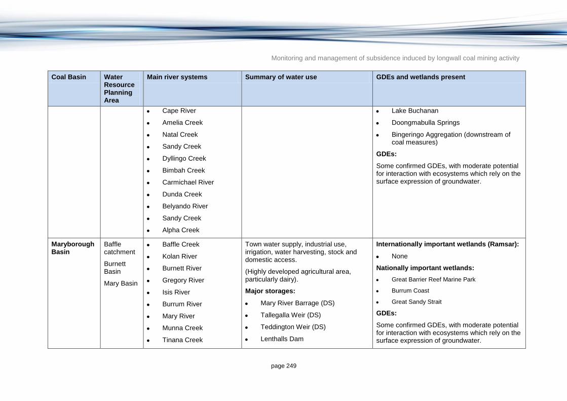
Monitoring and management of subsidence induced by longwall coal mining activity
page 249
Coal Basin Water Resource Planning Area
Main river systems Summary of water use GDEs and wetlands present
Cape River
Amelia Creek
Natal Creek
Sandy Creek
Dyllingo Creek
Bimbah Creek
Carmichael River
Dunda Creek
Belyando River
Sandy Creek
Alpha Creek
Lake Buchanan
Doongmabulla Springs
Bingeringo Aggregation (downstream of coal measures)
GDEs:
Some confirmed GDEs, with moderate potential for interaction with ecosystems which rely on the surface expression of groundwater.
Maryborough Basin
Baffle catchment
Burnett Basin
Mary Basin
Baffle Creek
Kolan River
Burnett River
Gregory River
Isis River
Burrum River
Mary River
Munna Creek
Tinana Creek
Town water supply, industrial use, irrigation, water harvesting, stock and domestic access.
(Highly developed agricultural area, particularly dairy).
Major storages:
Mary River Barrage (DS)
Tallegalla Weir (DS)
Teddington Weir (DS)
Lenthalls Dam
Internationally important wetlands (Ramsar):
None
Nationally important wetlands:
Great Barrier Reef Marine Park
Burrum Coast
Great Sandy Strait
GDEs:
Some confirmed GDEs, with moderate potential for interaction with ecosystems which rely on the surface expression of groundwater.

Monitoring and management of subsidence induced by longwall coal mining activity
page 250
Coal Basin Water Resource Planning Area
Main river systems Summary of water use GDEs and wetlands present
Burrum Weir No. 2
Burrum Weir No. 1
Gregory Weir
Bingera Weir
Woongarra Balancing Station
Ben Anderson Barrage
Kolan Barrage
Mulgildie Basin
Burnett Basin
Burnett River
Three Moon Creek
Splinter Creek
Town water supply, industrial use, irrigation, water harvesting, stock and domestic access.
Major storages:
Monto Weir (DS)
Bazley Weir
Avis Weir (DS)
Internationally important wetlands (Ramsar):
None
Nationally important wetlands:
None
GDEs:
No confirmed GDEs and very low potential for interaction with ecosystems which rely on the surface expression of groundwater
Styx Basin Not located in a planning area
Styx River
Tooloombah Creek
Town water supply, irrigation, stock and domestic access.
Low level of development of surface water resources.
Major storages:
Internationally important wetlands (Ramsar):
None
Nationally important wetlands:
Broad Sound
Great Barrier Reef Marine Park.

Monitoring and management of subsidence induced by longwall coal mining activity
page 251
Coal Basin Water Resource Planning Area
Main river systems Summary of water use GDEs and wetlands present
None GDEs:
No confirmed GDEs and low potential for interaction with ecosystems which rely on the surface expression of groundwater.
Surat Basin Fitzroy Basin
Condamine Balonne catchment
Upper Dawson River
Middle Condamine River
Maranoa River.
Town water supply, industrial use, irrigation, water harvesting, stock and domestic access
Major storages:
Warra Town Weir
Chinchilla Town Weir
Chinchilla Weir
Dogwood Creek Weir
Wallumbilla Weir
Bungeworgorai Weir (DS)
Neil Turner Weir (DS).
Internationally important wetlands (Ramsar):
None
Nationally important wetlands:
Boggomoss Springs
Palm Tree and Robinson Creeks
The Gums Lagoon (low risk)
GDEs:
A number of confirmed GDEs, with high potential for interaction with ecosystems which rely on the surface expression of groundwater.
Tarong Basin Burnett Basin
Moreton Basin
Barker Creek
Stuart River
Cooyar Creek
Emu Creek
Town water supply, irrigation, water harvesting, stock and domestic access.
Some industrial use, for power generation.
Major storages:
Tarong Ash Dam
Internationally important wetlands (Ramsar):
None
Nationally important wetlands:
None
GDEs:
No confirmed GDEs and low potential for

Monitoring and management of subsidence induced by longwall coal mining activity
page 252
Coal Basin Water Resource Planning Area
Main river systems Summary of water use GDEs and wetlands present
Meandu Creek Dam
Tarong Cooling Water Dam
Nanango Weir (DS)
Pukallus Weir (DS)
interaction with ecosystems which rely on the surface expression of groundwater.