monitor and control of cockroach locomotion with
TRANSCRIPT

MONITOR AND CONTROL OF COCKROACH LOCOMOTION WITH
PIEZOELECTRIC SENSORS
A Thesis
by
RODRIGO ALEJANDRO COOPER
Submitted to the Office of Graduate Studies of Texas A&M University
in partial fulfillment of the requirements for the degree of
MASTER OF SCIENCE
August 2008
Major Subject: Mechanical Engineering

MONITOR AND CONTROL OF COCKROACH LOCOMOTION WITH
PIEZOELECTRIC SENSORS
A Thesis
by
RODRIGO ALEJANDRO COOPER
Submitted to the Office of Graduate Studies of Texas A&M University
in partial fulfillment of the requirements for the degree of
MASTER OF SCIENCE
Approved by:
Chair of Committee, Hong Liang Committee Members, Richard Griffin Bradleigh Vinson Head of Department, Dennis O’Neal
August 2008
Major Subject: Mechanical Engineering

iii
ABSTRACT
Monitor and Control of Cockroach Locomotion with
Piezoelectric Sensors. (August 2008)
Rodrigo Alejandro Cooper, B.S., Texas A&M University
Chair of Advisory Committee: Dr. Hong Liang
Monitoring and controlling of insects are of great scientific and engineering
interests based on the potential impacts on environments, search and rescue operations,
and robotics design. This research focuses on studying insects’ locomotive behavior by
employing noninvasive piezoelectric sensors and presenting a conceptual method of
locomotion control. To do so, polyvinylidene fluoride thin sheets are used as bending
sensors at the joints of a cockroach’s legs. Approaches include development of
polymeric sensors; laboratory in vitro testing of sensors and cockroaches; and
methodology to control them. This research successfully built an experimental
foundation for sensor and roach testing and developed a methodology for roach
locomotion control. This research links engineering and entomology potentially having
impacts in the mentioned arenas.
Testing showed that piezoelectric films, such as polyvinylidene fluoride (PVDF),
can serve as motion sensors for the legs, providing frequency and range of motion of
each of the roach’s legs. The film is thin enough to provide as little resistance to motion
to prevent altering the roach’s natural walking patterns.

iv
Testing also showed that using the insect’s instinct to physically touch an
unknown object can be used as a directional control method. By using this natural
response, a device can be fit on the roach capable of guiding the roach in any direction
desired.
This thesis is organized to present a brief introduction on the history and need for
biomimetic robots. This section is followed by the research objectives and an
introduction to polyvinylidene fluoride and the piezoelectric properties that allow it to
become a sensor. A brief description of the roach anatomy and physiology is presented
that will provide baseline of information needed to proceed with the project. We finish
with an explanation of the testing of sensors on the roach and a novel method to control
the roach walking orientation.
v
ACKNOWLEDGEMENTS
I would like to thank my parents for instilling in me the dedication and desire to
further my education.
I would also like to thank Dr. Liang for all her support and assistance throughout
my studies, for without whom this research would have not reached its potential.
Special thanks go to Dr. J. Gonzales for sharing his knowledge and handling and
maintaining the roaches and Dr. S. Khatri for his support and assistance with electrical
and electronics issues.
The members of the Surface Science Lab are also thanked for their impromptu
conversations of advice and encouragement.
Finally, last but not least, I would like to thank Dr. B. Vinson and Dr. R. Griffin
for their support and motivation in developing this thesis and project.
Financial support for this project was provided by: National Science Foundation
(NSF) grant number IIS-0515930 and DARPA.

vi
TABLE OF CONTENTS
Page
ABSTRACT .................................................................................................................... iii
ACKNOWLEDGEMENTS .............................................................................................. v
TABLE OF CONTENTS ................................................................................................. vi
LIST OF FIGURES .......................................................................................................... ix
CHAPTER
I INTRODUCTION ......................................................................................... 1
1.1. Biomimetic robots ......................................................................... 1 1.2. Drawbacks ..................................................................................... 2 1.3. A new direction to biorobotics ...................................................... 4
1.3.1. Natural design advantages ................................................. 4
II MOTIVATION AND OBJECTIVES ............................................................ 6
2.1. Goals .............................................................................................. 6 2.2. Summary ....................................................................................... 7
2.2.1. Organization of paper ........................................................ 7
III BACKGROUND ........................................................................................... 8
3.1. Polyvinylidene fluoride (PVDF) ................................................... 8 3.1.1. Fabrication of piezoelectric polyvinylidene fluoride
(PVDF ) ............................................................................. 9 3.1.2. Piezoelectricity behavior ................................................. 12
3.1.2.1. Generalized equations for piezoelectricity ..... 13 3.2. Cockroach background ................................................................ 17
3.2.1. Cockroach mobility ......................................................... 17 3.2.1.1. Walking patterns ............................................. 18
3.2.2. Running and recovery ..................................................... 19 3.2.3. Effects of amputation ...................................................... 21 3.2.4. Stability control ............................................................... 22 3.2.5. Antennae .......................................................................... 23
3.2.5.1. Olfactory sensory ............................................ 25

vii
CHAPTER Page
3.2.5.2. Mechanical receptor ....................................... 25 3.2.5.3. Tactile wall-following methods ...................... 26
IV PVDF SENSOR DEVELOPMENT ............................................................ 28
4.1. Sensor fabrication ........................................................................ 28 4.1.1. Material drawbacks ......................................................... 30 4.1.2. Sensor dimensions ........................................................... 31
V LOCOMOTION MONITORING ................................................................ 32
5.1. Roach sensors .............................................................................. 32 5.1.1. Location ........................................................................... 33 5.1.2. Attachment methods ........................................................ 36
5.2. Walking platforms ....................................................................... 40 5.2.1. Roach trackball ................................................................ 41 5.2.2. Floating platform ............................................................. 43
5.3. Testing ......................................................................................... 44 5.3.1. Single sensor response .................................................... 45
5.3.1.1. Mechanical analogy ........................................ 45 5.3.1.2. Signal response ............................................... 47
5.3.2. Multiple sensor signal ..................................................... 50 5.3.2.1. Mechanical analogy ........................................ 51 5.3.2.2. Sensor attachment ........................................... 52 5.3.2.3. Robot response ............................................... 53
5.4. Roach signals ............................................................................... 56
VI LOCOMOTION CONTROL ....................................................................... 59
6.1. Electrical stimulation locomotion control ................................... 59 6.1.1. Drawbacks ....................................................................... 60
6.2. Behavioral stimulation locomotion control ................................. 62 6.2.1. Design concept ................................................................ 62 6.2.2. Device prototype ............................................................. 64 6.2.3. Proof of concept – roach trials ........................................ 65
6.2.3.1. Design limitations ........................................... 67 6.2.4. Proposed designs for moveable wall control ................... 67
6.2.4.1. Limitations ...................................................... 69 6.2.5. Future control designs ..................................................... 69

viii
CHAPTER Page
VII CONCLUSIONS ......................................................................................... 71
7.1. Future suggestions ....................................................................... 71
REFERENCES ................................................................................................................ 73
VITA ..................................................................................................................... 79
ix
LIST OF FIGURES
Page
Figure 1 Dr. Walter’s first robot turtle, Elmer, was capable of finding its charging station when its battery ran low[10]. ............................................... 2
Figure 2 Dante II on its voyage into a volcano. Although guided by human operators, Dante proved its ability at navigating through uneven terrain[10]. ......................................................................................... 3
Figure 3 Polyvinylidene Fluoride repeat mer. .......................................................... 10
Figure 4 During solidification of the PVDF melt, the polymer forms spherulites. [27] ............................................................................................ 11
Figure 5 Process for formation of PVDF β-phase. a) Melt cast b) aligned chains due to elongation c) dipole orientation due to poling[44]. ............... 12
Figure 6 Tensor directions used in following equations. [49] .................................... 13
Figure 7 Step patterns of slow walking roach. Black indicates protraction movement of the leg[55]. ............................................................................. 19
Figure 8 Recovery of American cockroach after 20 minutes of rapid running occurs within the first minute[59]. ................................................. 21
Figure 9 Amputation of the two middle legs of a roach[21]. ..................................... 22
Figure 10 Head of American cockroach with labeled antenna parts[65]. .................... 24
Figure 11 Rapid following of accordion-like wall demonstrates the roach’s use of its antenna during running[72]. ......................................................... 27
Figure 12 Sensor fabrication schematic profile view of sensor. ................................ 30
Figure 13 Sensor fitting onto roach leg[49]. ................................................................ 31
Figure 14 Simple anatomy of cockroach body parts. ................................................. 33
Figure 15 Simplified anatomy of roach leg. ............................................................... 34
Figure 16 Underside of cockroach shows the little space available for wires or attachments. ................................................................................. 35
x
Page
Figure 17 a)Silicon sample post-cmp cleaning collects dust particles on the surface from the environment if not maintained in a clean chamber. b)The surface of roach has a wax coating that prevents dust from collecting. The wax prevents any type of adhesive from bonding to the surface making sensor attachment a particular challenge. ................................................................................... 37
Figure 18 Blaberous Discoidalis is a larger cockroach than the American cockroach allowing for more rugged methods of sensor attachment and thicker sensors. ................................................................. 38
Figure 19 Sensor attachment to legs using heat shrinking tubing resulted in permanent damage to the legs although sensors were kept in place properly. ........................................................................................... 39
Figure 20 Latex paint around femur and tibia provide a good surface to bond or tape the sensors. Latex paint shrinks slightly while drying making bonding less of an issue. .................................................... 40
Figure 21 Two degrees of motion are required to measure the path of the cockroach. One degree should measure the forward motion of the roach while the other measures the lateral displacement. Motion only in the lateral direction means the roach is turning in place. ...................................................................................................... 42
Figure 22 Roach tracking device with roach held fixed with a beaker holder. As the roach tries to walk, it moves the ball which is tracked by the optical mouse. While Blaberous was capable of moving the ball with ease, Periplaneta had more difficulty and tired quickly. .............................................................................................. 42
Figure 23 Floating Parafilm® on water provides a low-resistance surface for the roach to walk on. One-directional movement of the film forced roach to move only in the forward direction. ................................. 44
Figure 24 A linear stage can approximate the same deformation expected on the roach leg allowing reasonable conclusions on the response of the sensor to be made under controlled conditions. ............... 46
Figure 25 Linear stage used for testing response of sensor. ...................................... 47
Figure 26 PVDF response at a constant deflection of 3mm with varying frequencies shows limiting voltage above 2Hz. ........................................ 48
xi
Page
Figure 27 PVDF response at a constant frequency of 3Hz with varying deflection amplitudes shows a linear response to bending. ....................... 49
Figure 28 Schematic of op-amp configuration to eliminate crosstalk amongst several signals collected simultaneously through the DAQ board. ................................................................................................ 51
Figure 29 Hexapod robot simulates tripod walking pattern of the cockroach for sensor validation. ................................................................ 52
Figure 30 Sensor locations for robotic roach. ............................................................ 53
Figure 31 Leg numbering system for analysis of signals. .......................................... 54
Figure 32 Signal response from three sensors on robot roach demonstrate offset cycle and increased amplitude of middle leg. .................................. 55
Figure 33 Signal response from six sensors on robotic roach show offset cycles between the two tripod systems. Sensor 2 later showed slight problems with adhesion on the roach, which caused the decay in the signal. .................................................................................... 56
Figure 34 Roach with four sensors installed, one on each of the mesothoracic and metathoracic legs at the femur-tibia joints. .................. 57
Figure 35 Roach signals indicate alternating pattern on hind legs, but little response from middle legs. ........................................................................ 58
Figure 36 Roach locomotion control device set for straight-line walk. ..................... 63
Figure 37 Roach locomotion control device set for left turn. .................................... 63
Figure 38 Roach locomotion control prototype for straight-line walk. ..................... 64
Figure 39 Roach locomotion control prototype for left turn. ..................................... 64
Figure 40 Roach with left turning device makes a counterclockwise circle during walking. .......................................................................................... 66
Figure 41 Roach with right turning device makes a clockwise circle during walking. ..................................................................................................... 66
Figure 42 EAP reacting to 3V causes the film to bend outward making it appear that the bent wall is removed. ........................................................ 68

xii
Page
Figure 43 Two EAP’s can be controlled simultaneously to provide the appearance of two walls present or absence of walls to make the roach stop. .................................................................................................. 68

1
CHAPTER I
INTRODUCTION
Before the middle of the last century, a book containing information on a specific
material like polyvinylidene fluoride (PVDF) the middle of the last century, engineers
have looked towards nature to solve some of the most basic problems with robotic
locomotion. To this date, our understanding of how animals maintain control during
walking is still limited largely by our technologies.
Development of a robot that can traverse through different terrains with little or
no modifications to their hardware has been an aspiration for rescue specialists and
geologists wanting to scout dangerous sites. This research brings a new direction to
biorobotics that may overcome the current engineering challenges with control and
power of robots[1]. The present work presents the foundations to developing a fully
functional robot by using a living organism, in this case the American cockroach, as the
working platform instead of developing a mechanical platform.
1.1. Biomimetic robots
Biomimetic robots are just what the name implies; robots that attempt to mimic
the natural movements of biological systems, mainly animals. Some of the earliest
accounts of biorobotics can be attributed to designs drawn by Leonardo da Vinci,
although these lacked a central processing system[2]. In 1950, Dr. Grey Walter developed
This thesis follows the style of Journal of Applied Physics.

2
what is considered by many the first form of artificial life with his creation of a robotic
turtle[3], shown in Figure 1, which would return to its charging station when its battery
ran low. Most robots have depended on the wheel for locomotion, but this method is
impractical for overcoming uneven or varying terrain. Many scientists have turned to
other species to find a solution to conquering different landscapes by use of legged
locomotion[4]. All types of animals have been studied and replicated including humans
for a bipedal robot[5], roaches for hexapods, to earthworms[6] and snakes for crawling
robots[7], and even bees and wasps for flying robots[8]. Despite several decades of study,
no robot has achieved the agility and control over irregular surfaces as well as any
animal[9].
Figure 1: Dr. Walter’s first robot turtle, Elmer, was capable of finding its charging station when its battery ran low. [10]
1.2. Drawbacks
What initially seemed like a simple idea of mimicking biology has proven much
more difficult. While control systems, mechanics, and muscle-like actuators have
improved recently, there is still much work remaining to make these robots fully

3
functional[11]. One of the most successful robots, Dante II, shown in Figure 2, proved its
agility by successfully walking into a volcano[12]. However, the robot lacked the ability
to recognize and avoid obstacles on its own and had to be guided by human operators,
and even then, the robot overturned and was incapable of righting itself.
Figure 2: Dante II on its voyage into a volcano. Although guided by human operators, Dante proved its ability at navigating through uneven
terrain. [10]
For smaller robots trying to imitate the size of insects, power becomes a large
issue[7]. The small size and volume of the robots limit the space for sensors, actuators,
computers, and batteries[13] making these robots of limited practicality.

4
1.3. A new direction to biorobotics
Until recently, engineers, biologists, and entomologists have focused on
understanding all aspects of animal including mechanics, muscle stimulation, synaptic
responses, reflexes, cerebral computations, and decision hierarchy. It has not been until
the last decade though that research has been put into attempting to control a biological
unit as a robot. By attempting to control a living organism, we avoid having to replicate
much of the technology already present in the animal. There is no need to develop a
control system to maintain stability of the animal, or find a power source capable of
traversing large distances, or determine the best mechanics and materials to allow it to
move like an animal, because it already is one.
1.3.1. Natural design advantages
Some of the most advanced robots designed to date are based on arthropods,
mainly due to their simple design that allows them to go anywhere[14]. Many arthropods
have developed different methods of climbing over a high obstacle or running through a
highly irregular surface. Such is the case of the cockroach and the reason why it is one of
the most studied insects for locomotion[15-17]. Early robotic designs mimicking roaches
developed robots with equal-length legs that could not climb over surfaces higher than
half their height, yet a roach can climb much higher obstacles due to their different sized
legs[18].
Studies on the biological systems are not limited to the mechanics of the animal;
they also include thought process and hierarchy and control mechanisms. What appears
to be a fairly simple task for humans to stand up is actually a compilation of thousands
5
of feedback controls relating the position, acceleration, velocity of the pertinent joints
and muscles. Insects, equally, respond to perturbations in their walk by a system of open
loop controls[19] that allow them to quickly respond to changes in the ground or other
external forces that might cause it to lose balance. This recovery of stability is seen to
happen within one leg stride[20].
Neurobiologists are also in the race to understanding roaches to get a better idea
of the neural processes that occur in an injured roach during walking. The cockroach is
capable of quickly adapting its walking mechanism to account for damaged or missing
legs without losing stability. Delcomyn found that amputation of one of the middle legs
caused the biggest changes in walking patterns when the roach walked slowly [21]. This
adaptation to a missing leg became less evident during rapid running at which point the
roach returned to its regular running pattern. Such ability to quickly process changes in
stride to maintain efficiency during walking or running are of great interest to robot
engineers trying to maintain a damaged robot upright.

6
CHAPTER II
MOTIVATION AND OBJECTIVES
Biorobotics engineers have focused on attempting to duplicate nature by making
robots that look, behave, and move similar to animals. By replicating what nature has
solved through millennia, scientists hope they can construct a robot capable of quickly
overcoming difficult terrain and maintaining upright stability and balance. This approach
has shown that the simple assumptions initially made about control and locomotion of
animals is not as easy as they had believed.
2.1. Goals
This research investigates the idea of going about a different way at developing a
new wave of biorobots. We suggest the idea of developing robots directly from a
biological platform thus eliminating the need for trying to replicate the complex
technology of the insect, the American cockroach. Before developing the technology
required to create a fully functional biorobot, it is necessary to have the basic knowledge
of how the roach moves and why it moves. This research is focused on two primary
objectives:
1. Develop a noninvasive system to monitor locomotion of insects with as minimal
intrusion as possible to minimize the alteration of the walking patterns that may
be caused by bulky or heavy sensors, and
2. Develop a system to control the locomotion of the American cockroach with a
consistent reliability.
7
In this research, we firstly investigate the progress biorobotics engineers have
accomplished in designing robots that mimic nature. We then continue with the
development of how a system for monitoring roach locomotion is created from the
sensor fabrication to the data collection system. Progress is then made by actually
measuring and recording actual walking data from a cockroach. This report finalizes
with a study into a noninvasive method of directional control of the roach that has shown
a high repeatability in lab tests.
2.2. Summary
The ability to use a natural organism as the foundation for a robot is of great
importance since it has already solved many of the challenges we encounter with
robotics today. The cockroach provides the ideal platform for this type of biorobot since
it is cheap, easily available, and has a simple neural network that makes working with
the insect easier than other animals. A system to monitor and control the direction of
travel is developed in this paper.
2.2.1. Organization of paper
This thesis is organized to present a brief introduction on the history and need for
biomimetic robots. This section is followed by the research objectives and an
introduction to polyvinylidene fluoride and the piezoelectric properties that allow it to
become a sensor. A brief description of the roach anatomy and physiology is presented
that will provide baseline of information needed to proceed with the project. We finish
with an explanation of the testing of sensors on the roach and a novel method to control
the roach walking orientation

8
CHAPTER III
BACKGROUND
New materials are being developed with fascinating properties that make them
applicable for a wide range of uses. Polyvinylidene fluoride (PVDF) is a relatively new
material with superb piezoelectric and biocompatible properties that give it a wide range
of applications. In this research, we present a novel use of PVDF as motion sensors for
small cockroaches.
3.1. Polyvinylidene fluoride (PVDF)
Piezoelectricity is the ability of certain materials to produce a polar electrical
charge at the instance of mechanical deformation. The word piezoelectricity comes from
the Greek piezin for ‘squeeze’ followed by electricity, loosely meaning the ability for a
material to produce electricity when squeezed.
Initial observations of a material that could produce an electric charge were
developed during the 4th century B.C. by Theophrastus on the stone tourmaline[22]. It was
observed that the rock would pick up ashes and other particles when heated, and release
them when cooled. It was believed that its ability to change properties could give some
sort of therapeutic healing properties[23]. Charles Linne was the first to relate the idea of
pyroelectricity to electricity by warming tourmaline and measuring its electric charge[23].
Further thermal testing of the stones brought the idea that the electric charge was more
dependent on the thermal expansion and contraction of the stone rather than on the
temperature itself.

9
Piezoelectricity in its true sense was discovered in 1880 by the Curie Brothers,
Jacques and Pierre. The Curie brothers reported tests on zinc-blend, tourmaline, cane
sugar, topaz, and quartz[24]. Initially not much use was found for such a characteristic
property. In 1918, quartz was used as a piezoelectric transducer for submarine
ultrasound.
It was not until the 1950’s and 60’s that further studies on piezoelectric materials
were aimed towards polymers. Kawai was the first to report a strong piezoelectric
property in polyvinylidene fluoride in 1969 which has resulted in a wide range of
applications[25], such as actuators, vibration controllers, ultrasound transducers, strain
sensors, microphones, energy harvesting, and many more[26].
3.1.1. Fabrication of piezoelectric polyvinylidene fluoride (PVDF )
Polyvinylidene fluoride (PVDF) is a long chain polymer with a repeated mer
chemical composition of CF2CH2 as shown in Figure 3. The molecular weight of PVDF
is approximately 100,000 g/mol for 2,000 repeat mer units. PVDF is a highly polar
polymer due to the negative charge of the fluoride on one end of the mer and the positive
charge of the hydrogen[27] on the other. The charge difference created by the fluoride and
hydrogen in the mer develops a dipole effect similar to a magnetic or electric dipole,
which are caused by the charge difference between the North and South ends of a
magnet or the positive and negative electrical terminals. The dipole can be characterized
by its dipole moment, a vector quantity, which depends on the magnitude of the charge
difference between the two ends and the distance between the charges. The dipole
moment for PVDF is approximately 7.59x10⁻³⁰ C-m (2.27D)[28].

10
H
C
F
C
FH
Figure 3: Polyvinylidene Fluoride repeat mer.
PVDF is synthesized from a gaseous form of vinylidene fluoride monomer by
free radical polymerization. It is formed into sheets by solution casting, spin coating, and
film casting. Each process develops different phase composition in the polymer[28, 29] and
additional steps are required to obtain the desired piezoelectric properties.
As the polymer cools, it solidifies and crystallizes into three main
conformations[30]: β phase with a planar zigzag (form I),α phase with form TGTG’ (form
II), and γ phase with T3GT3G’ (form III)[31-33],with the most common phases being the α
and β. A poling process, which is the application of a strong electric field across the
polymer film, during an annealing step of the polymer after it is cured, can produce
different crystal compositions in the polymer. Several other crystal structures have been
found by varying the poling and annealing conditions of the polymer[34, 35]. Once cured,
the crystal structures present in the PVDF can be identified by using x-ray scattering and
infrared transmission[28, 36, 37].
The phase of the crystal structure dictates the pattern of the alignment of the
dipoles. The α-phase structure has dipoles in opposite and alternating pattern causing a
partial cancellation of the dipole. The β-phase is composed by the alignment of the

11
dipoles in the same direction making it the most polar conformation and thus the highest
piezoelectric structure of PVDF[28].
During solidification of the PVDF melt, the polymer forms spherulites, shown in
Figure 4, during crystallization[38] which typically consist of chains in the α and γ
phases[32]. To achieve the β phase requires further processing of the polymer.
Figure 4: During solidification of the PVDF melt, the polymer forms spherulites. [27]
Mechanical deformation is induced to the film to break the spherulites and form
crystallites aligned in the direction of the deformation. By doing this below the melt
temperature, the chains are forced to extend, as opposed to move, forming the β-
phase[39]. Deformation of up to 700% may be attained during this process[28, 40, 41]. The
stretching of the chains does not necessarily force the dipoles to align, as seen in Figure
5. The randomly oriented dipoles need to be treated by plasma or corona discharge of
approximately 10kV normal to the surface to force alignment and increase

12
polarization[42, 43]. A polar crystalline phase dispersed within amorphous polymer allows
for the polarization required for piezoelectricity to occur.
Figure 5: Process for formation of PVDF β-phase. a) Melt cast b) aligned chains due to elongation c) dipole orientation due to poling[44].
While other polymers can experience piezoelectric properties[45], PVDF exhibits
the largest of these properties[39] with values of up to 7x10-12 C/N[25]
3.1.2. Piezoelectricity behavior
Piezoelectricity is a material property that relates an electrical response to a
mechanical deformation. Two main theories exist towards the development of the
electrical charge response. One theory is that the piezoelectric effect is a result of
trapped charges obtained during the poling process[46]. A more supported theory is that
the mechanical stress forces the polar crystalline regions to orient resulting in a charge
development[47]. There are four contributing factors that determine the piezoelectric
response of a material according to Broadhurst et al[48]: a) the presence of molecular
dipoles, b) the dipole’s ability to realignment, c) the ability to sustain the alignment, and
d) the material ability to strain when stressed. The piezoelectric response is dependent on
the polarization of the dipoles caused by changes in the dipole moments[27].

13
3.1.2.1. Generalized equations for piezoelectricity
Mechanical properties are typically noted in tensor notation to identify coupling
mechanisms. Piezoelectric properties not unlike other properties depend on the chain
direction and crystallization of the polymer. As previously mentioned, PVDF requires a
mechanical stretching to align the chains and exposure to an electric field to orient the
dipoles. Figure 6 shows the axis notation of the polymer with reference to the poling and
stretching directions.
Figure 6: Tensor directions used in following equations. [49]
Axis 1 is parallel to the strain direction, axis 2 is perpendicular to the strain, and
axis 3 is normal to the surface, through the thickness and parallel to the poling direction.
Shear planes 4, 5, and 6 are perpendicular to axis 1, 2, and 3 respectively.
Combination of σ (stress), ε (strain), D (electric displacement), and E (electric
field) produce the four piezoelectric constants shown in the following formulas[50, 51].
14
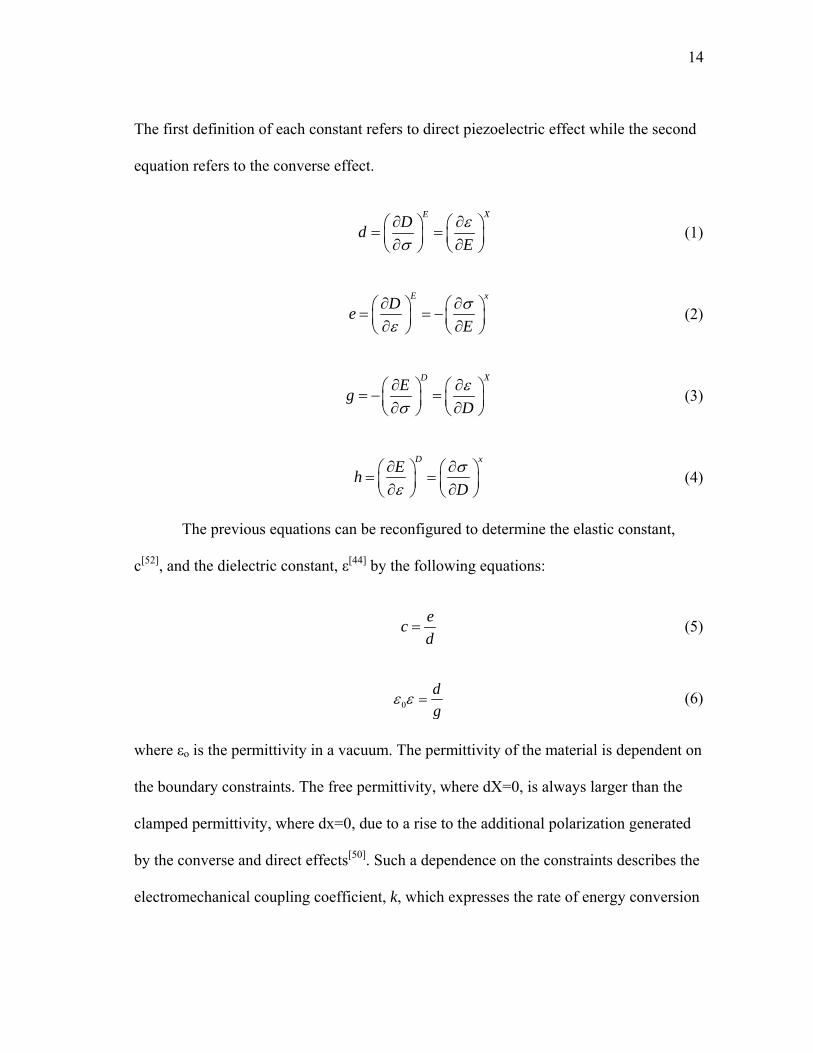
The first definition of each constant refers to direct piezoelectric effect while the second
equation refers to the converse effect.
E XDdEε
σ∂ ∂⎛ ⎞ ⎛ ⎞= =⎜ ⎟ ⎜ ⎟∂ ∂⎝ ⎠ ⎝ ⎠
(1)
E xDe
Eσ
ε∂ ∂⎛ ⎞ ⎛ ⎞= = −⎜ ⎟ ⎜ ⎟∂ ∂⎝ ⎠ ⎝ ⎠
(2)
D XEg
Dε
σ∂ ∂⎛ ⎞ ⎛ ⎞= − =⎜ ⎟ ⎜ ⎟∂ ∂⎝ ⎠ ⎝ ⎠
(3)
D xEh
Dσ
ε∂ ∂⎛ ⎞ ⎛ ⎞= =⎜ ⎟ ⎜ ⎟∂ ∂⎝ ⎠ ⎝ ⎠
(4)
The previous equations can be reconfigured to determine the elastic constant,
c[52], and the dielectric constant, ε[44] by the following equations:
ecd
= (5)
0dg
ε ε = (6)
where εo is the permittivity in a vacuum. The permittivity of the material is dependent on
the boundary constraints. The free permittivity, where dX=0, is always larger than the
clamped permittivity, where dx=0, due to a rise to the additional polarization generated
by the converse and direct effects[50]. Such a dependence on the constraints describes the
electromechanical coupling coefficient, k, which expresses the rate of energy conversion
15
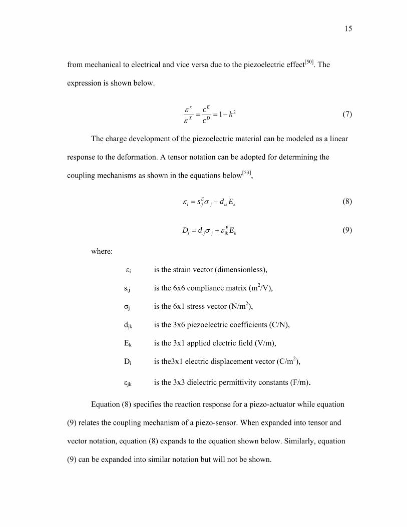
from mechanical to electrical and vice versa due to the piezoelectric effect[50]. The
expression is shown below.
21x E
X D
c kc
εε
= = − (7)
The charge development of the piezoelectric material can be modeled as a linear
response to the deformation. A tensor notation can be adopted for determining the
coupling mechanisms as shown in the equations below[53],
Ei ij j ik ks d Eε σ= + (8)
Ei ij j ik kD d σ ε= + E (9)
where:
εi is the strain vector (dimensionless),
sij is the 6x6 compliance matrix (m2/V),
σj is the 6x1 stress vector (N/m2),
djk is the 3x6 piezoelectric coefficients (C/N),
Ek is the 3x1 applied electric field (V/m),
Di is the3x1 electric displacement vector (C/m2),
εjk is the 3x3 dielectric permittivity constants (F/m).
Equation (8) specifies the reaction response for a piezo-actuator while equation
(9) relates the coupling mechanism of a piezo-sensor. When expanded into tensor and
vector notation, equation (8) expands to the equation shown below. Similarly, equation
(9) can be expanded into similar notation but will not be shown.

16
11 12 13 14 15 161 1
21 22 23 24 25 262
31 32 33 34 35 363
41 42 43 44 45 464
51 52 53 54 55 565
61 62 63 64 65 666
E E E E E E
E E E E E E
E E E E E E
E E E E E E
E E E E E E
E E E E E E
s s s s s ss s s s s ss s s s s ss s s s s ss s s s s ss s s s s s
ε σε σεεεε
⎡ ⎤⎡ ⎤⎢ ⎥⎢ ⎥⎢ ⎥⎢ ⎥⎢ ⎥⎢ ⎥
= ⎢ ⎥⎢ ⎥⎢ ⎥⎢ ⎥⎢ ⎥⎢ ⎥⎢ ⎥⎢ ⎥
⎢ ⎥ ⎢ ⎥⎣ ⎦ ⎣ ⎦
11 12 13
2 21 22 231
3 31 32 332
4 41 42 433
5 51 52 53
6 61 62 63
d d dd d d
Ed d d
Ed d d
Ed d dd d d
σσσσ
⎡ ⎤ ⎡ ⎤⎢ ⎥ ⎢ ⎥⎢ ⎥ ⎢ ⎥ ⎡ ⎤⎢ ⎥ ⎢ ⎥ ⎢ ⎥+⎢ ⎥ ⎢ ⎥ ⎢ ⎥⎢ ⎥ ⎢ ⎥ ⎢ ⎥⎣ ⎦⎢ ⎥ ⎢ ⎥⎢ ⎥ ⎢ ⎥⎢ ⎥ ⎢ ⎥⎣ ⎦ ⎣ ⎦
(10)
However, in the case of a sensor, the applied electric field component in equation
(10) is zero, and the expanded notation of this equation becomes[54]
1
21 1
32 24
43 31 32 33
5
6
0 0 0 0 00 0 0 0 0
0 0 0
D dD dD d d d
5
σσσσσσ
⎡ ⎤⎢ ⎥⎢ ⎥⎡ ⎤ ⎡ ⎤⎢ ⎥⎢ ⎥ ⎢ ⎥= ⎢ ⎥⎢ ⎥ ⎢ ⎥⎢ ⎥⎢ ⎥ ⎢ ⎥⎣ ⎦ ⎣ ⎦ ⎢ ⎥⎢ ⎥⎢ ⎥⎣ ⎦
(11)
where d31, d32, and d33 relate to the normal strain in the 1, 2, and 3 axis and d15
and d24 relate to the shear strain in the 1-3 plane. Equation (11) simplifies the
relationship between an applied stress and the electric displacement, D. Finally, the
charge generated by the piezoelectric material can be calculated by the following
equation
[ ]1
1 2 3 2
3
dAq D D D dA
dA
⎡ ⎤⎢ ⎥= ⎢ ⎥⎢ ⎥⎣ ⎦
∫∫ (12)
where dA1, dA2, dA3 are the electrode area components in the 2-3, 1-3, and 1-2 planes,
respectively.

17
3.2. Cockroach background
The American cockroach is one of the most abundant roaches in the world. Their
scientific name, Periplaneta americana, is an erroneous title since it is not originally
from the American continent. Periplaneta signifies ‘wandering star’ in Latin due to the
vast regions around the world where this insect is found.
In this report, understanding of two main aspects of the roach’s physiology is
necessary for development of the final product. This chapter briefly summarizes the
physiology of the American cockroach in terms of mobility and sensing. Topics
particularly important for very specific issues are discussed in further detail in the latter
chapters as they are needed. In this research, knowledge of the life expectancy,
differences between genders, life cycles, birth models, mating habits, etc. of the roach
are not necessary and will not be covered. Certain characteristics mentioned in this
chapter and proceeding chapters are not limited to the American cockroach, but will only
be discussed in terms of such.
3.2.1. Cockroach mobility
One of the most fascinating features of a cockroach is its walking mechanism.
The cockroach is capable of overcoming almost every obstacle presented in its path by
simple modifications to its walking patterns giving it the versatility to roam anywhere.
Skilled in wall climbing and quick to respond to a swatting broom, the cockroach
depends on a highly sensitive feedback control system and a simple neural system that
gives the insect the sharp reflexes to stimulus and terrain changes.

18
3.2.1.1. Walking patterns
Many six-legged insects depend on a walking system that allows them to
maintain balance by distributing their weight evenly on three legs at any time. Studies on
locomotion of six-legged insects have been conducted on stick insects, grasshoppers, and
cockroaches by means of visual inspection giving only a qualitative perspective on their
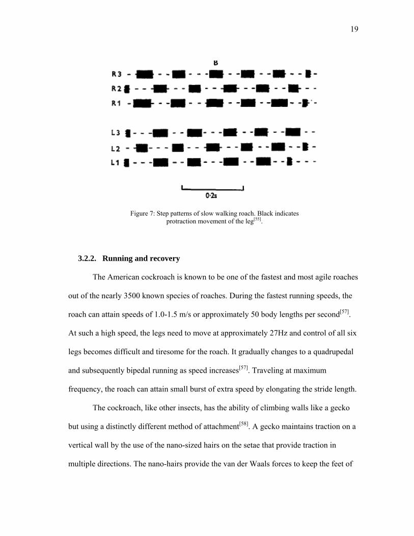
coordination[21]. Delcomyn performed the first of a series of quantitative measurements
on the roach walking mechanism by using a high-speed camera (200-500 frames per
second) [55]. Through tracking of the leg position and number of frame counts, Delcomyn
was able to reproduce an interpretation of the movement as shown in Figure 7, which
allowed for a quantitative measurement of the rate of protraction (forward movement of
the leg, solid black line) and retraction (backward motion of leg relative to body, dashed
line).
The tripod walking fashion of the roach is evident from the graphical
interpretation Delcomyn developed. The protraction versus retraction time is calculated
and used as a measure of varying gait timing to speed. The protraction segment of the
leg cycle is reported to have a duty cycle of about 60%[56].
19
Figure 7: Step patterns of slow walking roach. Black indicates
protraction movement of the leg[55].
3.2.2. Running and recovery
The American cockroach is known to be one of the fastest and most agile roaches
out of the nearly 3500 known species of roaches. During the fastest running speeds, the
roach can attain speeds of 1.0-1.5 m/s or approximately 50 body lengths per second[57].
At such a high speed, the legs need to move at approximately 27Hz and control of all six
legs becomes difficult and tiresome for the roach. It gradually changes to a quadrupedal
and subsequently bipedal running as speed increases[57]. Traveling at maximum
frequency, the roach can attain small burst of extra speed by elongating the stride length.
The cockroach, like other insects, has the ability of climbing walls like a gecko
but using a distinctly different method of attachment[58]. A gecko maintains traction on a
vertical wall by the use of the nano-sized hairs on the setae that provide traction in
multiple directions. The nano-hairs provide the van der Waals forces to keep the feet of

20
the gecko attached. Insects lack this setae and are required to used a combination of a
pretarsal claw and an attachment pad at the tarsi[58]. Because the claws of the roach are
unidirectional as opposed to the multidirectional setae of the gecko, the roach has to
orient the tarsi on the wall in such a way as to maintain forces upward and slightly
outward. The outward forces keep the roach from swaying from left to right as it climbs
the wall. During climbing, the roach can attain typical speeds of 5 body lengths per
second[58]. The lower limit of the speed is due to the inability for the roach to switch to a
quadrupedal running pattern without losing grip of the wall.
During rapid running, recovery time was studied by Herreid (1981 and 1984) [59,
60]. In his experiments, a roach was placed on a treadmill inside a sealed box to measure
the oxygen consumption and carbon dioxide produced. In his method, the consumption
of oxygen is related to the exhaustion of the insect. When the consumption of oxygen
after the exercise returns to normal, the roach is considered to have recovered. For the
majority of American cockroaches, recovery time is reported between 1-1.5 minutes for
fast running after 20 minutes, as shown in Figure 8.

21
Figure 8: Recovery of American cockroach after 20 minutes of rapid
running occurs within the first minute[59].
3.2.3. Effects of amputation
One of the many advantages of the roach is its ability to modify its walking
mechanism in order to compensate for differences in its structure caused by injury.
Amputation of the rear and middle legs of the roach cause the greatest change in the
walking pattern, as seen in Figure 9, although at higher speeds that difference may
become negligible and the roach will return to its normal walking pattern regardless of
which legs are amputated[21].

22
Figure 9: Amputation of the two middle legs of a roach[21].
Delcomyn reports that an amputation that leaves a leg long enough to touch the
ground causes almost negligible effect on the relative timing of each leg. An amputation
of a leg near the base of the leg closest to the body does not affect the relative timing of
the opposing gait, but the gait itself is changed. The gait becomes closer to the un-
amputated form as the roach reaches faster speeds. Despite this, the proportion of time
the remaining legs are on the ground versus the time they are lifted above the ground
remains practically unchanged[21].
3.2.4. Stability control
The roach has developed a very practical and efficient nervous control system
that allows it to modify its strides and posture in order to maintain balance. At speeds
approaching 30 body lengths per second, this becomes a challenge for most animals, and
yet the roach has mastered a way of maintaining balance.

23
The trick is in the simple nervous system of the roach which is composed of a
network of ganglia which control different parts of the body. Each leg is controlled by an
individual ganglion without having to be processed by the main ganglion. This is
analogous to having our arm reacting to a burning sensation without having to send the
‘hot’ signal from the fingers to the brain and wait for the brain to develop and send a
signal to the arm making it move away from the heat source. By eliminating the need to
process the signal through the brain, the response time is much quicker. The roach uses
this system to operate each leg independently with its respective ganglion while the
network of ganglia provides the global coordination for the six legs[61]. Sensory organs
in the legs provide the feedback control necessary for each ganglion to make the
adjustments necessary for stability[62, 63].
In this same manner, a roach is capable of recovering from perturbations during
walking with amazing agility without changing its walking strides. By quickly adjusting
the stiffness of a series of legs, a roach can recover from a lateral perturbation within
fractions of a second[20]. By making the legs the appropriate legs behave as a
viscoelastic, the roach is capable of restoring normal walking conditions without having
to alter any steps.
3.2.5. Antennae
The insect antennae is a highly complex yet sensitive organ[64] with multiple
sensory purposes. The cockroach antenna is composed of a scape, pedicel, and flagellum
as seen in Figure 10. Although there are no muscles in the flagellum segments of the

24
antenna, slight movement can be seen that is attributed to changes in hemolymph flows
within the antenna. The scape and pedicel provide the movement of the entire antenna.
This section introduces the basic functions of the cockroach antennae that will
provide the foundational theory on locomotion control explained in Chapter VI. The
neurological processes that occur during sensing, whether it is chemical or physical
sensing, are not important and will be neglected in this section. This section will be
focused primarily on the methods of sensing with the antennae.
flagellum
pedicel
scape
head
eye
scape
pedicel
flagellum
1 mm
Figure 10: Head of American cockroach with labeled antenna parts[65].

25
3.2.5.1. Olfactory sensory
The antenna of an insect is covered with all many types of sensors. The antenna
is covered with small hairs that throughout its surface that provide information on its
environment. A large network of fibers from proprioceptive and exteroceptive organs
extends through the antenna[66].
The antenna is equipped with various types of sensillum in the form of hairs on
the surface that allow it to detect different stimulus. These hairs have different structures
depending on the stimulus they are intended on detecting. Porous-walled hairs provide
the olfactory sense that gives the roach its acute chemical detection[65]. Gregarious
insects like the roach depend highly on olfactory senses to locate other roaches from its
own group by means of tracking chemical cues[67]. Sensitivity of the olfactory sense
depends on the type of chemical being tested, for example, alcohols would have a lower
response than female pheromones[68], and on wind conditions[69]. Injury to the flagellum
can cause a decrease in the ability of the roach to detect, or smell, chemicals. While
many insects can use the antennae as a tasting sensor, no such ability has been detected
on the roach, although similar hair receptors for taste can be found on the antennae[70].
3.2.5.2. Mechanical receptor
Schneider comments that long antennae on many insects are employed to
increase the number of chemical receptors to increase sensitivity. On close inspection of
several insects, including the roach, the density of the sensilla is too low to qualify as a
high sensitivity sensor[70]. Having such a long antenna without taking full advantage of
its surface with more sensors can only be explained by employing the antenna as feelers.

26
A special organ called the Johnston sense organ located at the pedicel functions
as a method of detecting mechanical oscillations and stresses. This mechanoreceptor is
used by the roach to detect position and forces on the antenna. The Johnston organ is the
organ that allows the roach to detect walls and wind perturbations on the antennae to
guide the roach. Although the roach has better mechanoreceptors on the cerci (the pair of
‘tails’ at the rear of the abdomen), these are ignored since they are not relevant to this
project.
3.2.5.3. Tactile wall-following methods
The mechanoreceptors in the antenna are used for more than just detecting
mechanical perturbations, but also as a tactile guidance system. Touching the antennae
can cause a quick escape response in static roaches. In performing escape maneuvers, a
roach uses its antennae as a tactile means of guidance and obstacle avoidance. During
running along a wall, the roach drags its ipsilateral antenna along the wall while
maintaining the pedicel and scape at nearly a constant angle relative to the body[71]. The
dragging of the flagellum provides the feedback response required to maintain constant
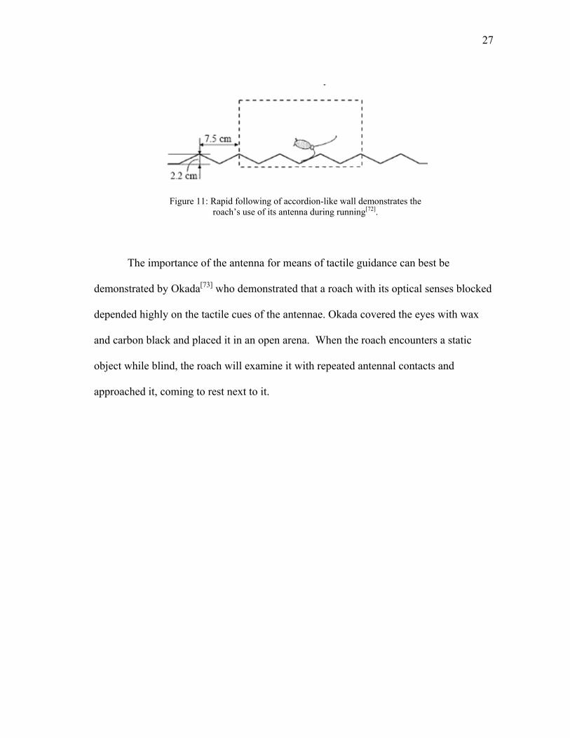
distance from walls or other objects. In an experiment determined to monitor the use of
the antennae during running as shown in Figure 11, the roach was put to run along an
accordion wall and recorded[72]. It was seen that at faster speeds when optical cues
cannot be processed fast enough, the antenna is kept in contact with the wall for longer
periods than during slow running with contact time averages of 73% and 49%,
respectively.
27
Figure 11: Rapid following of accordion-like wall demonstrates the roach’s use of its antenna during running[72].
The importance of the antenna for means of tactile guidance can best be
demonstrated by Okada[73] who demonstrated that a roach with its optical senses blocked
depended highly on the tactile cues of the antennae. Okada covered the eyes with wax
and carbon black and placed it in an open arena. When the roach encounters a static
object while blind, the roach will examine it with repeated antennal contacts and
approached it, coming to rest next to it.

28
CHAPTER IV.
PVDF SENSOR DEVELOPMENT
4.1. Sensor fabrication
Several considerations have to be taken into account in the development of a
piezoelectric sensor. The size and geometry must be such that the roach can easily
deform and the material properties should allow an accumulation and transport of the
piezoelectric charge.
Previous studies by B. Mika were prepared for Blaberous Discoidalis, a much
larger and stronger roach than Periplaneta americana. The thickness of the sensors for
these larger roaches was of less concern since the roach showed a good ability to
properly deform the sensors. When dealing with American roaches, this factor plays a
much larger importance when determining the material to be used for the sensor.
Silver-coated polyvinylidene fluoride films (Measurement Specialties Inc,
Hampton VA) were used for this experiment. Common thicknesses of 28, 52, and
110μm are too stiff for the American roach to bend, disabling the joints at which these
sensors would be attached. Specialty films of 9μm thick and 3μm thick coat were
employed.
Magnet copper wires approximately 0.0047” in diameter were used as leads from
both coated faces of the sensor. The magnet wire has the advantage of being thin enough
to eliminate bulky wires and having a thin, flexible polymer coating for insulation.
Insulation is removed approximately 1/8” from the end to provide a good contact with

29
the sensor coating. The insulation is removed by scrapping the surface of the wire with a
sharp razor blade.
Although several wire connection methods are widely available in commercial
use, the small size of the wires and the small space where the sensors would fit on the
roach eliminates most of the common techniques. Two main methods were tested in this
research: conductive silver epoxy and clear adhesive tape. Conductive epoxy proved to
be too costly and the curing time proved to be a deterrent due to its long setting time.
The cured product resulted in a very rigid structure, if for any reason the PVDF would
bend at the edge of the cured epoxy, the rigidity of the epoxy would not give and would
peel off the sensor removing part of the metal coating. The epoxy has a tendency to form
a bead while drying, making attachment to the roach much more difficult. Clear tape was
considered for its good bonding characteristics and ability to bend with the sensor,
preventing major damage to the sensor. The tape also allowed for a flexible flat surface
that could be easily formed to the roach leg. The tape is used to attach the wires as
shown in Figure 12, extending approximately 1/8” into the sensor.

30
Figure 12: Sensor fabrication schematic profile view of sensor.
4.1.1. Material drawbacks
The thinness of the PVDF film required for use on the American cockroach is not
without its drawbacks. Special attention needs to be paid when cutting the film not to
squeeze the polymer, which may cause the two coatings to come into contact and disable
the sensor. The material is also less robust, making handling a difficult challenge when
static cling of the material to skin and paper come into effect. Physical damage to the
sensor is likely as the sensor will tend to roll onto itself due to static electricity moments
before attempting to press on it. The small thickness dimension also produces a lower
output than thicker films.

31
4.1.2. Sensor dimensions
Roach anatomy is a very important factor to consider when designing sensors for
the American roach. The sensors should be sufficiently large enough to produce a signal
large enough to be measured but also small enough that it can be easily applied to the
roach and the roach is able to bend the sensor.
Not all roaches are the same size. The adult size of the roach depends on
nutrition, climate, and injuries during molting[74]. A standard sensor size had to be
chosen considering an average anatomy of the cockroach to allow for an easier
production of numerous of sensors. As seen in Figure 13, an appropriately placed and
sized sensors should be about the width of the back of the leg of the roach and long
enough to extend between two parts of the leg.
It was decided by observation that a sensor 1.5mm wide and 13mm long would
be sufficient to fulfill both requirements.
Figure 13: Sensor fitting onto roach leg[49].

32
CHAPTER V.
LOCOMOTION MONITORING
Like all other arthropods, the American cockroach does not have a skeletal
system like mammalian animals. Instead, the cockroach benefits from an exoskeleton,
allowing for a more compact muscular system and reducing the muscle to mass ratio.
This is also of great advantage in measuring the locomotion characteristics of the
cockroach. Placement of the piezoelectric sensors is made easier when attaching to a
hard surface than a softer surface such as hair or skin.
5.1. Roach sensors
All cockroaches, as well as many other arthropods, employ a walking mechanism
of alternating tripod gaits requiring less energy to maintain balance and climb uphill as
opposed to bipeds. Arthropods are characterized by their segmented body composed of
multiple annular segments which have blended to form parts of the body such as the
thorax and abdomen on the roach, as seen in Figure 14. The thorax has three particular
segments that hold one pair of legs each; the prothoracic legs extending from the
foremost annular segment of the thorax and the metathoracic leg initiating from the
hindmost annular segment.

33
Figure 14: Simple anatomy of cockroach body parts.
5.1.1. Location
Proper placement of the sensors on the cockroach leg is of great importance to be
able to collect valuable data in determining their locomotion. Several concerns need to
be taken into account when deciding the location of the sensor on the cockroach:
1) The sensors should be located on a joint that bends instead of rotates (i.e. an
elbow as opposed to a shoulder) which could provide the bending
deformation required of the sensors to produce a signal,
2) The muscles of the particular joint should be strong enough to be able to bend
the sensor and exhibit minimal discomfort to the animal that would otherwise
cause an altered walking pattern, and
3) The joint should be easily accessible and strong enough to prevent accidental
amputation during fitting which may also cause an altered walking pattern.
A simplified cockroach leg is presented in Figure 15 with the main leg segments
identified. For purposes of this paper, the joint between the Coxa and Femur will be

34
referred to as C-F, between the femur and tibia as F-T, and between the tibia and tarsi as
T-Ta.
Figure 15: Simplified anatomy of roach leg.
The roach leg is composed of three main joints, neglecting the joint at the body.
The C-F and F-T joints both exhibit a simple bending mechanism similar to the human
knee. While these joints have some movement in other axis, these movements are
limited and minimal when compared to the range of motion of in the bending mode
allowing us to model these joints as a one-degree of freedom joints[56]. The T-Ta joint,
more like the human ankle, has a greater range of rotational and tilting motion that
would prevent proper bending of the sensors.
The exoskeleton permits the cockroach a higher efficiency of its muscle system
as opposed to animals with an endoskeleton. This higher efficiency means that a body
part will be as small as possible while still performing its intended task. With this in

35
mind, the joint at the C-F is surrounded by the largest muscles making it the strongest
joint and most capable of effectively bending the piezoelectric sensor.
Of equal importance to strength is the joint’s accessibility and ability to have the
sensors attached to it. As seen in Figure 16, the C-F joint is set very close to the main
body which makes it hard to manipulate properly. Although the F-T joint is smaller in
size and inherently weaker than the C-F, its accessibility makes it the ideal testing joint
for this experiment.
Figure 16: Underside of cockroach shows the little space available for
wires or attachments.

36
5.1.2. Attachment methods
The cockroach is known to inhabit most every type of environment from rainy
jungles to arid deserts. In each environment, these animals are known to scavenge nearly
any meal possible ranging from human wastes, dead animals, foliage, glue, paper, and
even other roaches. Most of the environments where roaches can find these meals are
dirty with dust, dirt, and allergens. At such a small size, extra weight due to dirt and dust
might impede the roach’s agility or hinder their camouflage. Yet a simple observation of
the cockroach coming out from the yard will indicate that this is not so.
The cockroach, like many other insects and some plants[75], is protected by a
waxy coating[76-82] to prevent water loss through the cuticle. The waxy coating is
believed to be a thin layer of a tacky wax with a thick liquid coating on top. This waxy
coating has the advantage of also preventing dust particles from collecting on the
surface. Figure 17 shows an AFM scan of a poorly cleaned Si sample (figure 17.a)
compared to a sample of the roach cuticle with no cleaning (figure 17.b). It is evident
that no dust was collected on the roach cuticle even without cleaning.

37
a) b)
Figure 17: a)Silicon sample post-cmp cleaning collects dust particles on the surface from the environment if not maintained in a clean chamber.
b)The surface of roach has a wax coating that prevents dust from collecting. The wax prevents any type of adhesive from bonding to the
surface making sensor attachment a particular challenge.
This waxy coating also added the challenge of properly attaching the sensors to
the legs since nearly no adhesive is capable of bonding with wax or its liquid coating.
Initial tests on Blaberous Discoidalis allowed the sensor to be attached using a thin strip
of Parafilm® stretched tightly around the roach’s leg wrapping the sensor in place, as
seen in Figure 18. Blaberous Discoidalis is a larger roach than Periplaneta americana and
is more robust and resistant to injury and amputation. Because of Periplaneta’s
proneness to amputation, this method was deemed unsuitable and more troublesome and
discarded from future testing for Periplaneta.

38
Figure 18: Blaberous Discoidalis is a larger cockroach than the
American cockroach allowing for more rugged methods of sensor attachment and thicker sensors.
Bonding agents and Parafilm® discarded, new methods had to be improvised in
the attachment of sensors to the roach that took into consideration the fragility of the
animal’s legs. Shrinking materials were chosen due to the ability to be fixed to the leg by
pressure instead of bonding, eliminating the obstacle of the waxy coating. Initially,
shrinking wire insulation tubing was cut in small segments and placed at the desired
points on the leg as seen in Figure 19. With the sensors in place, the tubing was shrunken
with the use of a soldering iron to apply localized heat to the tubing only. It was later
found that the heat required to shrink the tubing caused permanent muscle damage and
discarded from future testing.

39
Figure 19: Sensor attachment to legs using heat shrinking tubing resulted in permanent damage to the legs although sensors were kept in
place properly.
A latex paint was employed due to its slight shrinking during drying and ability
to form around the spines on the leg, as seen in Figure 20. The latex paint provides a
small patch to which the sensor can then be glued or taped. The paint thickness and
weight contribution is sufficiently small enough to not produce any noticeable walking
abnormalities on the cockroach.

40
Figure 20: Latex paint around femur and tibia provide a good surface to
bond or tape the sensors. Latex paint shrinks slightly while drying making bonding less of an issue.
To further prevent any walking abnormalities, the wires of the sensors were led
away from the body to prevent any entanglement with other wires and also to prevent
any discomfort to the roach.
It was finally decided that for proper testing of the roach locomotion, the sensors
would have to be tested mainly on the metathoracic legs, which provide the most
impulse during walking and thus the greatest amount of information about the walking.
The femur-tibia joint is selected as the most reliable joint for testing since it offers the
greatest range of motion, is easily accessible, and strong enough to bend the sensors.
5.2. Walking platforms
During regular walking, a cockroach can travel at speeds of 1.3 m/s, equivalent
to approximately 40 body lengths per second and achieving a leg frequency of
approximately 25Hz[57, 83].
41
Sensor attachment to the cockroach legs is not always exact, leaving room for
variations of the attachment such as one sensor is fixed with less slack than other, or one
end of the sensor is attached a little offset causing the sensor to bend a little during
buckling. These variations in attachment can result in different results of the signals
which can lead to a misinterpretation if not calibrated properly. Two calibration systems
had to be developed to allow the cockroach as much liberty of motion as possible and
maintain it in one location to keep it from dragging the wires and other equipment.
The two systems developed were meant to provide a means of calibration of the
sensors to a known walking velocity and direction while maintaining walking pattern as
close as possible to the roach’s natural patterns.
5.2.1. Roach trackball
A simple device was developed capable of recording the trail traversed by the
roach during a suspended free walk. The roach was suspended and held in place over a
lightweight Styrofoam ball that rested on a low friction box. The roach rotates the ball as
it attempts to walk on it. By tracking the motion of the ball, the walking direction, speed,
and acceleration of the roach can be obtained. Two degrees are required to measure the
path of the cockroach, as shown in Figure 21, one for the forward direction, and the
other for the lateral movements.

42
Figure 21: Two degrees of motion are required to measure the path of the cockroach. One degree should measure the forward motion of the
roach while the other measures the lateral displacement. Motion only in the lateral direction means the roach is turning in place.
In order to record the two degrees of motion of the ball, a simple optical mouse
was used to maintain friction to a minimum by avoiding any mechanical contact to the
ball. The assembled tracking system is shown in Figure 22 with the roach walking on the
ball. This system permits the roach to walk on an endless surface, allowing it to choose
its own direction and speed.
Figure 22: Roach tracking device with roach held fixed with a beaker
holder. As the roach tries to walk, it moves the ball which is tracked by the optical mouse. While Blaberous was capable of moving the ball
with ease, Periplaneta had more difficulty and tired quickly.

43
The optical mouse (Logitech) was then connected to a Linux system programmed
to collect information from the mouse regarding position and time, which could then be
interpreted into a path and provide speed and acceleration of the roach. Comparison of
the signal acquired from the mouse and that of the sensors would provide the calibration
necessary for each sensor.
Blaberous Discoidalis showed little effort in moving the Styrofoam ball as it tried
to walk and was able to produce adequate signals. On the other hand, Periplaneta, being
a smaller and weaker roach, exhibited much stress when walking on the ball and limited
its walking distances.
5.2.2. Floating platform
A walking platform with lower resistance than the trackball previously
mentioned had to be developed specifically for the American cockroach. The new
platform would also have to provide information on the direction and speed the roach
was walking. Mechanical components required to be kept at a minimum to prevent
excess resistance to motion.
A thin film of Parafilm® over a pool of water proved to be sufficiently light
enough for the roach to move on its own. Unfortunately, the pool of water made
measuring the movement of the Parafilm difficult and the speed and direction of the
roach could not be gathered this way. By limiting the motion of the film to only one
direction (along the length of the roach) and pulling on the film at a constant speed, the
walking trail of the roach can be assumed as a straight path and constant speed which
can ease the calibration process. The walking platform is shown in Figure 23. The roach

44
was then held in place on the Parafilm in the same manner as employed for the trackball
monitoring system. By pulling on the film, the roach is forced to walk on the film as
opposed to allowed to walk freely on the trackball.
To calibrate the sensors using this walking platform, it is necessary to pull on the
film at a constant velocity and attempt to maintain the roach walking on the surface
instead of dragging over it.
Figure 23: Floating Parafilm® on water provides a low-resistance
surface for the roach to walk on. One-directional movement of the film forced roach to move only in the forward direction.
5.3. Testing
Testing of the sensors is required to get a good understanding of what the signal
response will be to different bending conditions. Mechanical analogies are implemented
which will provide a controlled deformation capable of producing a voltage signal
through the sensor. The voltage signal can then be correlated to the known deformation
and thus produces a reliable interpretation of the actual bending conditions it will
encounter on the roach.

45
5.3.1. Single sensor response
Piezoelectric materials produce an electric charge when deformed, but not all
piezoelectric materials behave the same nor do they respond the same to different
deformation conditions. It is therefore important to be able to identify the response
qualities of the PVDF sensors to be used on the roaches.
5.3.1.1. Mechanical analogy
Since it is too difficult to measure the range of motion of a cockroach while
simultaneously recording the bending of the sensor, a linear stage apparatus was
employed that would loosely mimic the movement of the roach. The linear stage can be
programmed to reproduce specific movements in one direction with control of position
and speed.
The linear stage can be programmed to reproduce programmable displacements
set by the user. One stage is maintained fixed and the other is motorized by an actuator
controlled with a PID controller. When the sliding stage approaches the fixed stage, the
sensors is buckled in such a manner that could be compared to the bending deformation
expected to occur in the roach leg, as seen in Figure 24. The rapid extension and bending
of the roach leg during walking can be imitated by causing a reciprocating motion of the
stage to buckle the sensor and return it to the extended position continuously.

46
Roach Leg Testing Apparatus
Extended position Extended position
Buckled position Buckled position
Figure 24: A linear stage can approximate the same deformation expected on the roach leg allowing reasonable conclusions on the
response of the sensor to be made under controlled conditions.
The actual linear stage is shown in Figure 25. The two ends of the sensor are
gently pinched under glass slides to keep them in place on the stage holders. The sensor
is monitored to ensure that the pinching under the plastic slide does not cause any
stresses on the sensor that could result in a voltage signal.

47
Figure 25: Linear stage used for testing response of sensor.
5.3.1.2. Signal response
Signal response to different conditions needed to be studied to determine how the
PVDF responded and what conditions had a greater effect on the signal output. Two
studies were carried to determine the signal response of the sensor: one to test the
dependence on frequency of the deformation another to test the dependence of
deformation amplitude (displacement) of the sensor.
To study the dependence of deformation frequency, the linear stage was set to
reproduce a controlled displacement in a reciprocal motion at different frequencies while
maintaining the same displacement value. Several programs were made to deflect the
sensor ends by 3mm at interval frequencies. Likewise, dependence on deformation was
studied by maintain the deformation frequency to 3Hz and varying the deformation
amplitude in increments ranging from 1mm to 3.5mm.
48
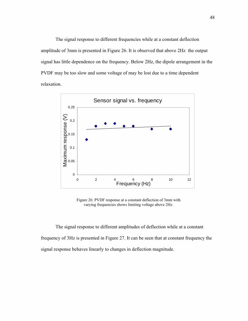
The signal response to different frequencies while at a constant deflection
amplitude of 3mm is presented in Figure 26. It is observed that above 2Hz the output
signal has little dependence on the frequency. Below 2Hz, the dipole arrangement in the
PVDF may be too slow and some voltage of may be lost due to a time dependent
relaxation.
Sensor signal vs. frequency
0
0.05
0.1
0.15
0.2
0.25
0 2 4 6 8 10 1Frequency (Hz)
Max
imum
resp
onse
(V
2
)
Figure 26: PVDF response at a constant deflection of 3mm with varying frequencies shows limiting voltage above 2Hz.
The signal response to different amplitudes of deflection while at a constant
frequency of 3Hz is presented in Figure 27. It can be seen that at constant frequency the
signal response behaves linearly to changes in deflection magnitude.

49
Sensor signal vs. deflection
0
0.05
0.1
0.15
0.2
0.25
0 1 2 3 4Deflection (mm)
Max
imum
resp
onse
(V
5
)
Figure 27: PVDF response at a constant frequency of 3Hz with varying deflection amplitudes shows a linear response to bending.
The limiting voltage in the constant deflection with varying frequency (Figure
26) occurs due to the limited time allowed for the dipoles to reorient. Below 2Hz, it is
presumed that the deformation is slow enough to allow for the movement of chains in
response to the stress applied. This allows the chains to stretch and move without a
realignment of the dipoles. At higher frequencies, the chains cannot move as easily
causing a realignment of the dipoles and creating a charge limited only by the width and
thickness of the sensors. The constant frequency with varying deflection (red triangles)
increases linearly due to the increased number of dipoles realigned at higher
deformations. The larger deformation realigns more dipoles which result in the linear
response of signal to the sensors; refer to equations (11) and (12) for this linearity.

50
Since a roach’s typical walk can attain leg motion frequencies of 25Hz, it is presumed
that the frequency of the motion will have a minute effect on the signal compared to the
deformation. Had the sensor responded linearly to frequency as well as amplitude of
deformation, a direct correlation would be too difficult to accomplish.
5.3.2. Multiple sensor signal
Due to the high impedance of PVDF, data acquisition of multiple signals
becomes a challenge due to crosstalk of the inputs at the data acquisition board. Cross
talk is the interference caused by one circuit on another circuit. The way that the data
acquisition system collects data from multiple signals is that each channel is measured
individually in sequential order. If the impedance of the artifact being measured is too
high, the circuitry in the data acquisition board does not have the ability to discharge the
voltage from the previously scanned signal, which it reads as the signal for the current
channel.
The electrical properties of PVDF are very poor for the polymer itself without the
coating. The impedance is such that crosstalk occurs when an independent signal is
simulated and the channel measuring the PVDF sensors repeats a similar curve even
though there is no deformation occurring in the sensor.
A series of op-amps set in a unity gain configuration assisted in the acquisition of
data from multiple sensors without cross talk. The noninverting input of the op-amp is
connected to the ground reference of the sensor by a large resistance (5kΩ) to provide a
reference state for the sensor. The configuration is shown in Figure 28.
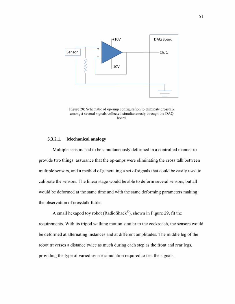
51
+
+10V
‐10V
Ch. 1
DAQ Board
Sensor _
Figure 28: Schematic of op-amp configuration to eliminate crosstalk amongst several signals collected simultaneously through the DAQ
board.
5.3.2.1. Mechanical analogy
Multiple sensors had to be simultaneously deformed in a controlled manner to
provide two things: assurance that the op-amps were eliminating the cross talk between
multiple sensors, and a method of generating a set of signals that could be easily used to
calibrate the sensors. The linear stage would be able to deform several sensors, but all
would be deformed at the same time and with the same deforming parameters making
the observation of crosstalk futile.
A small hexapod toy robot (RadioShack®), shown in Figure 29, fit the
requirements. With its tripod walking motion similar to the cockroach, the sensors would
be deformed at alternating instances and at different amplitudes. The middle leg of the
robot traverses a distance twice as much during each step as the front and rear legs,
providing the type of varied sensor simulation required to test the signals.

52
Figure 29: Hexapod robot simulates tripod walking pattern of the
cockroach for sensor validation.
5.3.2.2. Sensor attachment
Appropriate locations for the placement of the sensors on the robot roach were
much easier to find than on the actual roach, but it is still important to identify the proper
locations for placement. Since the robot can tolerate higher stresses than the roach, the
thicker, 28μm thick PVDF sensors were used since they are more robust and easier to
handle.
Pivoting joints were the most attractive since they represented the actual
movement of the roach leg more closely than any other joints. Three sensors were
applied to the robot roach as shown in Figure 30.
Initially, superglue was used to attach the sensors to the robot legs but it became
evident that some of the glue was seeping onto the sensor where the wires make contact.
Being nonconductive, the superglue formed an insulating coating between the wires and
the sensors making them nonresponsive. The sensors were fixed to the robot using clear
tape around each of the leg members. Despite repeated efforts, the tape was not capable
of maintaining the ends of the sensors perfectly in place on the leg. Other methods of
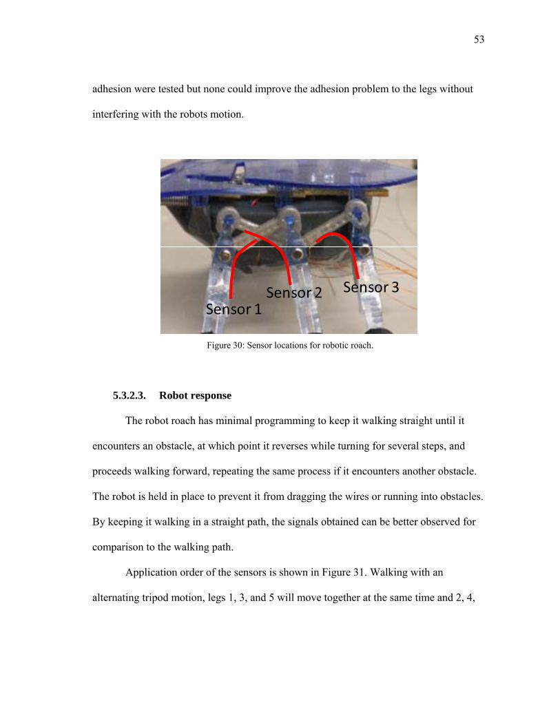
53
adhesion were tested but none could improve the adhesion problem to the legs without
interfering with the robots motion.
Sensor 1Sensor 2 Sensor 3
Figure 30: Sensor locations for robotic roach.
5.3.2.3. Robot response
The robot roach has minimal programming to keep it walking straight until it
encounters an obstacle, at which point it reverses while turning for several steps, and
proceeds walking forward, repeating the same process if it encounters another obstacle.
The robot is held in place to prevent it from dragging the wires or running into obstacles.
By keeping it walking in a straight path, the signals obtained can be better observed for
comparison to the walking path.
Application order of the sensors is shown in Figure 31. Walking with an
alternating tripod motion, legs 1, 3, and 5 will move together at the same time and 2, 4,

54
and 6 will move opposite to the first set. Legs 1, 3, 4, and 6 travel half the distance that 2
and 5 travel during the length of one stroke.
Figure 31: Leg numbering system for analysis of signals.
Figure 32 shows the signal response from sensors 1, 2, and 3 of the robot. It can
be observed that the signal from sensor 2 is much larger than the other two signals,
which is to be expected. It is also noticed that the two sets of signals are offset by 90°, or
half a cycle, which also to be expected since the two sets behave separately but opposite
to each other.
It is also important to mention the consistency of the signals showing that there is
no adding of voltage at each cycle and that each cycle develops its own independent
charge.

55
Figure 32: Signal response from three sensors on robot roach demonstrate offset cycle and increased amplitude of middle leg.
When collecting data from all six legs, as shown in Figure 33, the same
alternating cycle is shown. It is also important to mention that sensors 2 and 5 pertaining
to the two middle legs have the greatest signal amplitude. The amplitude of sensor 2 is
seen to decay due to a loosening of the sensor from the leg resulting in a progressively
lower deformation for each consecutive cycle.

56
Figure 33: Signal response from six sensors on robotic roach show offset cycles between the two tripod systems. Sensor 2 later showed
slight problems with adhesion on the roach, which caused the decay in the signal.
5.4. Roach signals
Due to the complexity of the legs and the cramped space available at the thorax,
only four sensors were able to be applied. Furthermore, due to the smaller size of the
prothoracic legs, it is believed that those legs may not have the sufficient strength to
deform the sensors and were hence omitted from testing.
The sensors were placed on the roach in such a way that the lead wires were
directed away from the body and towards the tarsi, as shown in Figure 34. Number
labels for each leg are also shown to make analysis of the data easier. The roach was
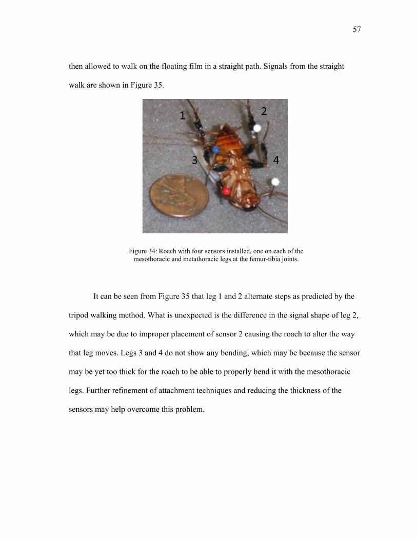
57
then allowed to walk on the floating film in a straight path. Signals from the straight
walk are shown in Figure 35.
Figure 34: Roach with four sensors installed, one on each of the mesothoracic and metathoracic legs at the femur-tibia joints.
It can be seen from Figure 35 that leg 1 and 2 alternate steps as predicted by the
tripod walking method. What is unexpected is the difference in the signal shape of leg 2,
which may be due to improper placement of sensor 2 causing the roach to alter the way
that leg moves. Legs 3 and 4 do not show any bending, which may be because the sensor
may be yet too thick for the roach to be able to properly bend it with the mesothoracic
legs. Further refinement of attachment techniques and reducing the thickness of the
sensors may help overcome this problem.

58
Figure 35: Roach signals indicate alternating pattern on hind legs, but little response from middle legs.

59
CHAPTER VI.
LOCOMOTION CONTROL
Locomotion control of any living organism is a complicated challenge, no matter
how simple the organism is. The cockroach provides as simple of a testing platform for
testing locomotion control as it could get. With a simple nervous system and a highly
instinctual response, the roach can be tested for multiple methods of locomotion control.
6.1. Electrical stimulation locomotion control
One of the most studied methods of locomotion control for many insects is
through electrical stimulation. The location of the stimulus can vary between the cerebral
cortex, a single ganglion, to muscular stimulation.
Muscular cues to move are derived from motoneurons, which drive the muscles
and provide signals to produce a certain force at a particular speed. The motoneurons
behave like capacitors, and depending on the charge buildup in the neuron and the
frequency of charge spikes produced determine the force of the muscle[84]. The
accumulation of several of these spikes produces an integration of small muscular
movements that buildup to the desired muscle output.
Many scientists have performed studies on how motoneuronal responses affect
walking in a roach. Pearson and Pichon studied the control of muscles by tapping into
the nervous system to record motor reflexes [85-87]. Zilber-Gachelin and Iles studied the
reflex response of muscles due to motoneuronal stimulus[88, 89]. Muscular stimulation and
response was studied by Spence [90] by constructing a multielectrode array capable of
recording the electrical response of legs. Hue and Hess studied the synaptic transmission

60
through the ganglia during walking [91, 92] and the effects of damaged ganglia on
stimulation responses.
All of these methods required a measurement of an electrical signal produced in
the body, be it through the nervous system or the muscles themselves, to measure the
responses and reactions of the cockroach legs. While these measurements recorded
naturally occurring electrical currents present during movement, it is easy to understand
that an equal electrical stimulation applied by an external source to any of these organs
can produce an equal reaction of the appropriate muscles.
One such experiment using electrical stimulation was performed by Holzer et
al[93]. His experiment required multiple electrodes be implanted into the cockroach’s
cerebral ganglion and produce electrical discharges to control steering. The magnitude
of the electrical stimulation was found to correlate directly to the degree of turning
during walking.
6.1.1. Drawbacks
Electrical stimulation on any organ of the cockroach has its downfalls making it
more of an unpractical method of locomotion control than actually perceived. The most
obvious of these drawbacks is the necessity to perform microsurgery on the roach to
implant the microelectrodes. Not only is this task complicated in trying to connect the
electrodes to the appropriate ganglia or nerve cords, but the unavoidable cutting of the
exoskeleton causes permanent damage to the cockroach reducing its life expectancy
greatly.

61
The exoskeleton of the roach can be compared to the human skin in the manner
in which it controls the moisture content within the body by making minute adjustments.
Unlike humans, though, which control moisture content by varying the size of the pores
on the skin, a roach’s cuticle cannot be as easily modified and is in a constant state of
transpiration, controlled only by the amount of wax secretion produced at the surface[94-
96]. By making perforations on the cuticle of the roach, the cuticle’s ability to maintain
moisture content within the organism will be diminished. In lab experiments, we have
found roaches to die within one to three days after making small perforations on the legs.
Damage to the muscles was also observed during improper electrode insertion causing
permanent paralysis of the leg.
Furthermore, and even of greater importance is the fact that roaches, like many
other insects and vertebrate animals, develop a habituation to a stimulus which reduces
the extent of the response until almost no response is notable [97]. Holzer reported a
controlled response from the cockroach for only a matter of seconds due to a high level
of standard deviation caused by sensory habituation. We studied this characteristic decay
of response by inserting two electrodes in the roach’s leg and applying 2Vdc spikes.
After several consecutive spikes, the roach’s response was negligible, but an increase in
voltage recovered a response, until that again disappeared. Zilber-Gachelin et al. make
reference to other authors that have studied this habituation to electrical stimulus and
should be reviewed if more information on the topic is desired.

62
6.2. Behavioral stimulation locomotion control
The roach’s circadian activity is highest at night making visual cues limited to
obsolete. A roach overcomes this challenge by using its antennae as a tactile sensory and
olfactory organ to guide it. The olfactory sense is evident by a roach’s ability to find
food in our kitchens, and their tactile sense is most noticeable when we turn on the lights
and see the roach running along the walls until it finds a suitable hiding place. The roach
uses the antennae to feel the wall and maintain a safe distance from it and making it a
difficult target for their natural predators.
6.2.1. Design concept
Because this is a deeply rooted behavioral response as opposed to a reflex, we
focus on this idea to develop a roach locomotion device which, in idea, should not have
a decaying response from the roach.
Several design considerations had to be taken into account during the design and
development of a device that will fool the roach into believing it is following a wall.
Special regard was taken to weight constraints. Lab testing of several roaches showed
roaches to be able to carry 5 grams without much alteration to the walking patterns. The
device also has to be small enough to be portable by the roach. It should also have the
ability to be easily modifiable to present different conditions to the roach to induce
different directional responses.
To provoke a straight-line walk, the device is configured to have two walls on the
outside of the antennae to simulate a long narrow channel as shown in Figure 36. As

63
other stimulus is applied forcing the roach to walk, the walls on either side of the
antennae cause the roach to believe it is trapped in a channel and walk straight.
Figure 36: Roach locomotion control device set for straight-line walk.
Similar to walking along a single wall, setting the device with only one wall as
depicted in Figure 37 fools the roach to believe it is following a wall on one side. As it
tries to approach the wall, the wall keeps moving away fooling the roach to continue
turning.
Figure 37: Roach locomotion control device set for left turn.

64
6.2.2. Device prototype
Simple devices with fixed walls similar to those previously depicted were created
to test the feasibility of controlling the roach through behavioral stimulus. A device with
two fake walls along the sides of the antennae is shown in Figure 38 and one with only
one wall in Figure 39. A similar device to that shown in Figure 39 was designed to make
the roach turn right.
Figure 38: Roach locomotion control prototype for straight-line walk.
Figure 39: Roach locomotion control prototype for left turn.

65
These first sets of prototypes were constructed using a stiff plastic strap. A
second prototype employed lighter and thinner materials that reduced the effect of
weight on the roach.
6.2.3. Proof of concept – roach trials
The second design of prototypes employing lighter materials than those shown
above were attached to the cockroach. Twenty roaches were tested to provide
repeatability, although there is no exact measure of quality to which they followed the
predicted path. The trials were performed in an open room with no notable air currents
or thermal gradients.
The roaches were first tested with the device with their eyes uncovered to test if
the weight of the device had any effect on their walking patterns. In fact, with their eyes
uncovered and the single-wall device on their backs, the roaches walked away from the
device’s wall trying to avoid it. At best, the roaches walked forward but with no notable
interest in the fake wall. With the double-wall device, the roaches walked erratically
trying to find somewhere to hide. The roaches did not demonstrate any altered walking
patterns in terms of limping or dragging legs due to the excess weight of the device.
The eyes were then covered with white liquid correction tape to blind completely
the roaches. Without the use of their eyes, the roaches are completely dependent on their
antennae for guidance.
Motion film was taken to record the travel path of the cockroach and sequential
screenshots of the movies are shown in the following images. With the device set to
make the roaches turn left, the roaches formed a counterclockwise circle as shown in

66
Figure 40. Similarly, the roaches fitted with the device to make them turn right formed
clockwise circles as shown in Figure 41.
Figure 40: Roach with left turning device makes a counterclockwise circle during walking.
Figure 41: Roach with right turning device makes a clockwise circle during walking.
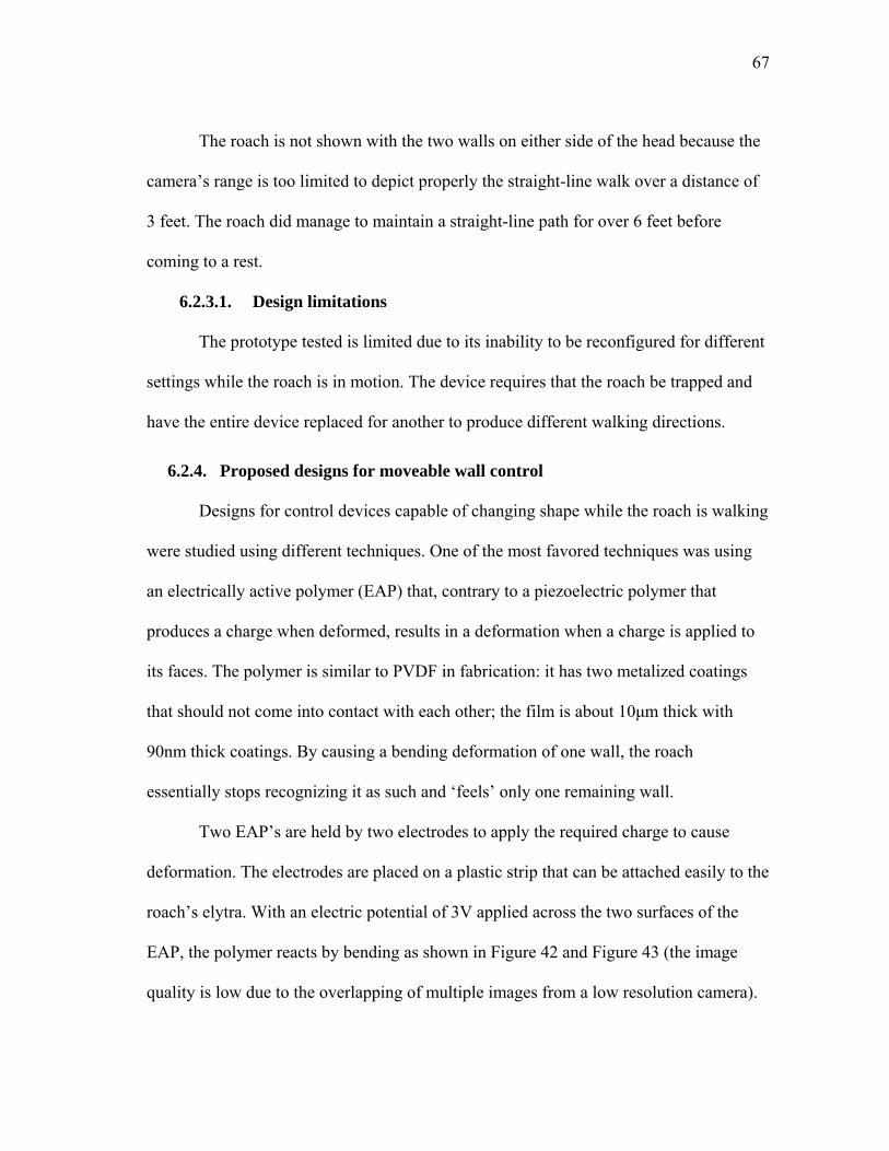
67
The roach is not shown with the two walls on either side of the head because the
camera’s range is too limited to depict properly the straight-line walk over a distance of
3 feet. The roach did manage to maintain a straight-line path for over 6 feet before
coming to a rest.
6.2.3.1. Design limitations
The prototype tested is limited due to its inability to be reconfigured for different
settings while the roach is in motion. The device requires that the roach be trapped and
have the entire device replaced for another to produce different walking directions.
6.2.4. Proposed designs for moveable wall control
Designs for control devices capable of changing shape while the roach is walking
were studied using different techniques. One of the most favored techniques was using
an electrically active polymer (EAP) that, contrary to a piezoelectric polymer that
produces a charge when deformed, results in a deformation when a charge is applied to
its faces. The polymer is similar to PVDF in fabrication: it has two metalized coatings
that should not come into contact with each other; the film is about 10μm thick with
90nm thick coatings. By causing a bending deformation of one wall, the roach
essentially stops recognizing it as such and ‘feels’ only one remaining wall.
Two EAP’s are held by two electrodes to apply the required charge to cause
deformation. The electrodes are placed on a plastic strip that can be attached easily to the
roach’s elytra. With an electric potential of 3V applied across the two surfaces of the
EAP, the polymer reacts by bending as shown in Figure 42 and Figure 43 (the image
quality is low due to the overlapping of multiple images from a low resolution camera).

68
Figure 42 shows the bending of one EAP to produce a configuration similar to that
shown in Figure 37 to cause the roach to turn.
Figure 42: EAP reacting to 3V causes the film to bend outward making it appear that the bent wall is removed.
Figure 43: Two EAP’s can be controlled simultaneously to provide the appearance of two walls present or absence of walls to make the roach
stop.

69
The two EAP’s can also be deformed simultaneously to make it appear that both
walls are present making the roach walk forward. Contrary to having both walls present,
by bending both walls out the roach can be fooled to believe there are no walls present.
In the absence of walls and with no perturbations to its system, to roach should come to
a stop.
6.2.4.1. Limitations
Several limitations of the system currently presented make it an unviable method
for roach control. The current system of EAP requires too much electric power that
cannot be sustained by batteries small enough to be carried by the roach. The setup
shown in the previous images was powered by a constant DC voltage. In addition, the
amount of deformation of the EAP is not sufficiently large enough or fast enough to trick
the roach to the disappearance of the wall. Furthermore, placement of the walls in
relation to the body became an unsuspected difficulty. Placing the walls too close to the
body make it easy for the roach to hold on to and thus eliminating the effect of the fake
wall. Placing the walls too far from the body allows the antennae to slip to the other side
of the walls so that both walls are inside the antennae and thus eliminating the effect of
the fake wall as well.
6.2.5. Future control designs
A simple device consisting of an electromagnetic coil to move the walls into
place is currently being created. Electromagnets have a high response time making the
motion of the walls adequately fast. Testing of current electromagnetic coils with small
batteries provide power to the electromagnetic coil for approximately one minute.

70
Refinement of the coil and increased magnetic power of the permanent magnets can help
reduce the power consumption. Currently, this device has not yet been tested due to
construction limitations.

71
CHAPTER VII.
CONCLUSIONS
New approaches were utilized to develop novel techniques in monitoring and
controlling of cockroaches. This research conducted investigation in three areas,
synthesis of piezoelectric polymer sensors; developed methodology to monitor
cockroaches; and found a way to control the same insects with a noninvasive approach.
Results have brought a new perspective on the ability to control and monitor
cockroaches. The two main goals were achieved with certain efficacy:
• A system of piezoelectric sensors capable of monitoring the cockroach’s
locomotion through the bending of the femur-tibia joint was developed. It was
determined, both from previous experiments and from our own, that at this
joint provides the most effort into locomotion and is thus the strongest and
most accessible for sensor attachment.
• A system to control the locomotion direction of the cockroach has been
achieved by utilizing the roach’s natural behavior. By using this mechanism
instead of forced locomotion through electrical stimulation, we provide a
method of control without a decay in response.
7.1. Future suggestions
Development should continue on a better method of moving the side walls of the
device. Using electromagnets instead of EAP’s could provide for a faster response with
less energy consumption. In addition, methods of monitoring the mesothoracic and

72
prothoracic legs still need to be developed. Currently, fabrication processes limit the
thickness of PVDF films at 9μm, still too thick for these legs to bend. Finally, a fully
functional program to analyze and interpret the signals from the sensors needs to be
created to obtain real time information on the walking mechanism.

73
REFERENCES
1 B. Klaassen, R. Linnemann, D. Spenneberg and F. Kirchner, Robotics and Autonomous Systems 41 69-76 (2002)
2 J. Enderle. UConn Biomedical Engineering "Da Vinci" Robot. (2003).
3 J.M. Cañas and V. Matellán, Robotics and Autonomous Systems 55 841-850 (2007)
4 H.R. Marc, Commun. ACM 29 499-514 (1986)
5 Proceedings of the 1999 IEEE/ASME International Conference on Advanced Intelligent Mechatronics, Atlanta (pp561-568, 1999).
6 Proceedings of the 2004 IEEE International Conference on Robotics and Automation, (pp 5007-5012, 2004).
7 B. Kim, M.G. Lee, Y.P. Lee, Y. Kim and G. Lee, Sensors and Actuators A: Physical 125 429-437 (2006)
8 N. Franceschini, F. Ruffier and J. Serres, Current Biology 17 329-335 (2007)
9 F. Delcomyn, Signal Processing Magazine, IEEE 25 134-137 (2008)
10 Jaeger. Visual Journal - Robot History, http://pages.cpsc.ucalgary.ca/~jaeger/visualMedia/robotHistory.html. (accessed May 2008)
11 F. Delcomyn, Annual Review of Entomology 49 51-70 (2004)
12 J.E. Bares and D.S. Wettergreen, The International Journal of Robotics Research 18 621-649 (1999)
13 I. Shimoyama, H. Miura, K. Suzuki and Y.A.E.Y. Ezura, Control Systems Magazine, IEEE 13 37-41 (1993)
14 R.E. Ritzmann, S. Gorb and R.D. Quinn, Arthropod Structure & Development 33 183-185 (2004)
15 M.E. Fred, Robotics and Autonomous Systems 30 5-15 (2000)
16 J.G. Cham, J.K. Karpick and M.R. Cutkosky, The International Journal of Robotics Research 23 141-153 (2004)

74
17 R.E. Ritzmann, R.D. Quinn and M.S. Fischer, Arthropod Structure & Development 33 361-379 (2004)
18 R.E. Ritzmann, R.D. Quinn, J.T. Watson and S.N. Zill, BioScience 50 23-33 (2000)
19 Proceedings of the 2001 ICRA/ IEEE International Conference on Robotics and Automation, (pp 3643-3649, 2001).
20 D.L. Jindrich and R.J. Full, J Exp Biol 205 2803-2823 (2002)
21 F. Delcomyn, J Exp Biol 54 453-469 (1971)
22 S.B. Lang, Physics Today 58 (2005)
23 S.B. Lang, Ferroelectrics 230 99 - 108 (1999)
24 J. Curie and P. Curie, C. R. Acad Sci. Paris 294-383 (1880)
25 H. Kawai, Japanese Journal of Applied Physics 8 975-976 (1969)
26 S.B. Lang and S. Muensit, Applied Physics A: Materials Science & Processing 85 125-134 (2006)
27 M.G. Broadhurst, G.T. Davis, J.E. McKinney and R.E. Collins, Journal of Applied Physics 49 4992-4997 (1978)
28 G.M. Sessler, The Journal of the Acoustical Society of America 70 1596-1608 (1981)
29 K. Tashiro, H. Tadokoro and M. Kobayashi, Ferroelectrics 32 167 - 175 (1981)
30 Y. Takahashi and H. Tadokoro, Macromolecules 13 1317-1318 (1980)
31 M.A. Bachmann and J.B. Lando, Macromolecules 14 40-46 (1981)
32 A.J. Lovinger, Macromolecules 14 322-325 (1981)
33 S. Weinhold, M.H. Litt and J.B. Lando, Macromolecules 13 1178-1183 (1980)
34 G.T. Davis, J.E. McKinney, M.G. Broadhurst and S.C. Roth, Journal of Applied Physics 49 4998-5002 (1978)
35 A.J. Lovinger, Macromolecules 15 40-44 (1982)

75
36 J.P. Luongo, Journal of Polymer Science Part A-2: Polymer Physics 10 1119-1123 (1972)
37 D. Glennon, P.A. Cox, R.T. Nevell, T.G. Nevell, J.R. Smith, J. Tsibouklis and R.J. Ewen, Journal of Materials Science 33 3511-3517 (1998)
38 H.D. Keith and F. J. Padden, Jr., Journal of Applied Physics 35 1270-1285 (1964)
39 A.J. Lovinger, Science 220 1115-1121 (1983)
40 G. Gerliczy and R. Betz, Sensors and Actuators 12 207-223 (1987)
41 E.L. Nix, L. Holt, J.C. McGrath and I.M. Ward, Ferroelectrics 32 103 - 114 (1981)
42 J.E. McKinney, G.T. Davis and M.G. Broadhurst, Journal of Applied Physics 51 1676-1681 (1980)
43 P.D. Southgate, Applied Physics Letters 28 250-252 (1976)
44 J.S. Harrison and Z. Ounaies, ICASE Report No. 2001-43, NASA (2001)
45 A. Ballato, Tech. Rep. SLCET-TR-89-1, U.S. Army Lab Command, Fort Monmouth, NJ (1989)
46 N. Murayama, T. Oikawa, T. Katto and K. Nakamura, Journal of Polymer Science: Polymer Physics Edition 13 1033-1047 (1975)
47 R.G. Kepler and R.A. Anderson, Journal of Applied Physics 49 1232-1235 (1978)
48 M.G. Broadhurst and G.T. Davis, eds. Electrets. (Springer-Verlag, Berlin, 1980).
49 B. Mika. Design and Testing of Piezoelectric Sensors. Mechanical Engineering, (2007).
50 T. Furukawa, Electrical Insulation, IEEE Transactions on [see also Dielectrics and Electrical Insulation, IEEE Transactions on] 24 375-394 (1989)
51 T. Furukawa, J.X. Wen, K. Suzuki, Y. Takashina and M. Date, Journal of Applied Physics 56 829-834 (1984)
52 J. Su. Ferroelectric Polymers for Electromechanical Functionality. Electroactive Polymers for Robotic Applications, (Springer, London, pp. 91-120 2007).

76
53 T.R. Meeker, IEEE Transactions on Ultrasonics, Ferroelectrics, and Frequency Control 176 (1987)
54 J. Sirohi and I. Chopra, Journal of Intelligent Material Systems and Structures 11 246-257 (2000)
55 F. Delcomyn, J Exp Biol 54 443-452 (1971)
56 J. Schmitt and P. Holmes, Physica D: Nonlinear Phenomena 156 139-168 (2001)
57 R.J. Full and M.S. Tu, J Exp Biol 156 215-231 (1991)
58 D.I. Goldman, T.S. Chen, D.M. Dudek and R.J. Full, J Exp Biol 209 2990-3000 (2006)
59 C.F. Herreid and R.J. Full, Journal of Insect Physiology 30 395-403 (1984)
60 C.F. Herreid, II, R.J. Full and D.A. Prawel, J Exp Biol 94 189-202 (1981)
61 D. Price, IEEE Expert: Intelligent Systems and Their Applications 10 67-70 (1995)
62 P. Holmes, R.J. Full, D. Koditschek and J. Guckenheimer, SIAM Rev. 48 207-304 (2006)
63 D.M. Wilson, J Exp Biol 43 397-409 (1965)
64 Proceedings of the 1995 IEEE/RSJ International Conference on Human Robot Interaction and Cooperative Robots, (pp 530-535, 1995).
65 G. Seelinger and T. Tobin. Sense Organs. The American Cockroach, pp. 217-245 (Chapman and Hall, London, 1981).
66 D. Schaller, Cell and Tissue Research 191 121-139 (1978)
67 R. Jeanson and J.-L. Deneubourg, J Exp Biol 209 4768-4775 (2006)
68 W.M. Getz and R.P. Akers, Journal of Comparative Physiology A: Neuroethology, Sensory, Neural, and Behavioral Physiology 180 701-709 (1997)
69 M.A. Willis and J.L. Avondet, J Exp Biol 208 721-735 (2005)
70 D. Schneider, Annual Review of Entomology 9 103-122 (1964)
71 N.J. Cowan, J. Lee and R.J. Full, 209 1617-1629 (2006)

77
72 J.M. Camhi and E.N. Johnson, J Exp Biol 202 631-643 (1999)
73 J. Okada and Y. Toh, International Congress Series 1269 57-60 (2004)
74 W. Bell and K.G. Adiyodi. The American Cockroach. (Chapman and Hall, London, 1981).
75 A.C. Chibnall, S.H. Piper, A. Pollard, E.F. Williams and P.N. Sahai, Biochemistry Journal 28 2189-2208 (1934)
76 M.W. Holdgate and M. Seal, J Exp Biol 33 82-106 (1956)
77 J.A. Ramsay, J Exp Biol 12 373-383 (1935)
78 P.C. Croghan and J. Noble-Nesbitt, J Exp Biol 143 537-541 (1989)
79 S. Kramer and V.B. Wigglesworth, Quarterly Journal of Microscopical Science s3-91 63-72 (1950)
80 K.H. Lockey, J Exp Biol 37 316-329 (1960)
81 E.H. Dusham, Journal of Morphology 31 563-581 (1918)
82 J.W.L. Beament, J Exp Biol 32 514-538 (1955)
83 R.J. Full and M.S. Tu, J Exp Biol 148 129-146 (1990)
84 T.A. Hudson, J.A. Bragg and S.P. DeWeerth, Potentials, IEEE 18 36-39 (1999)
85 K.G. Pearson, J Exp Biol 56 173-193 (1972)
86 Y. Pichon and J.J. Callec, J Exp Biol 52 257-265 (1970)
87 J.J. Callec, J.C. Guillet, Y. Pichon and J. Boistel, J Exp Biol 55 123-149 (1971)
88 N.F. Zilber-Gachelin and M.P. Chartier, J Exp Biol 59 383-403 (1973)
89 J.F. Iles, J Exp Biol 56 647-656 (1972)
90 A.J. Spence, K.B. Neeves, D. Murphy, S. Sponberg, B.R. Land, R.R. Hoy and M.S. Isaacson, Journal of Neuroscience Methods 159 116-124 (2007)
91 A. Hess, Journal of Morphology 103 479-501 (1958)
92 B. Hue, M. Pelhate, J.J. Callec and J. Chanelet, J Exp Biol 65 517-527 (1976)

78
93 Proceedings of the 1997 IEEE/RSJ International Conference on Intelligent Robots and Systems, (pp1514-1519, 1997).
94 J.W.L. Beament, J Exp Biol 35 494-519 (1958)
95 V.B. Wigglesworth, J Exp Biol 21 97-114 (1945)
96 J.W.L. Beament, J Exp Biol 36 391-422 (1959)
97 N.F. Zilber-Gachelin and M.P. Chartier, J Exp Biol 59 359-381 (1973)

79
VITA
Name: Rodrigo Alejandro Cooper
Address: Texas A&M University c/o: Dr. Hong Liang Department of Mechanical Engineering TAMU 3123 College Station, TX 77843 Email Address: [email protected] Education: B.S., Mechanical Engineering, Texas A&M University, 2006 M.S. Mechanical Engineering, Texas A&M University, 2008