mohawk a proposed fiber positioner for ms-desi will saunders, greg smith, jamie gilbert, lew waller,...
TRANSCRIPT
MohawkA proposed fiber positioner for MS-DESIWill Saunders, Greg Smith, Jamie Gilbert, Lew Waller, Tony Farrell, Gabriella Frost,
Andy Sheinis, Peter Gillingham, all AAO
MS-DESI meeting, LBL
5th March 2013

MS-DESI positioner requirements:• 4000-5000 actuators needed to do survey in realistic timescale.
• Target density >2000 galaxies/deg2, not possible in single pass.
• Positions must be good to <10m, preferably ~5m.
• Focal surface is curved, to maintain telecentricity.
• Reconfiguring must take less than read-out or slewing time, ~60s.
• Each actuator used thousands of times, design must be reliable and modular.
DESpec reuses existing DECam WFC, 2.2 FOV. Focal surface limited to 450mm, at a speed ~f/3.0.
• Hexagonal layout preferred (modular, and tiles the sky more efficiently).
• To cover DES area (5000 deg2) in ~300 nights requires only 2 passes. require ~4000 actuators, at a pitch ~6mm. Echidna-derived design was only existing viable technology.
DESpecific requirements:
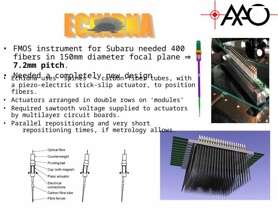
• FMOS instrument for Subaru needed 400 fibers in 150mm diameter focal plane 7.2mm pitch.
• Needed a completely new design.
• Echidna uses 'spines’ – carbon-fiber tubes, with a piezo-electric stick-slip actuator, to position fibers.
• Actuators arranged in double rows on ‘modules’• Required sawtooth voltage supplied to actuators by
multilayer circuit boards.• Parallel repositioning and very short
repositioning times, if metrology allows.
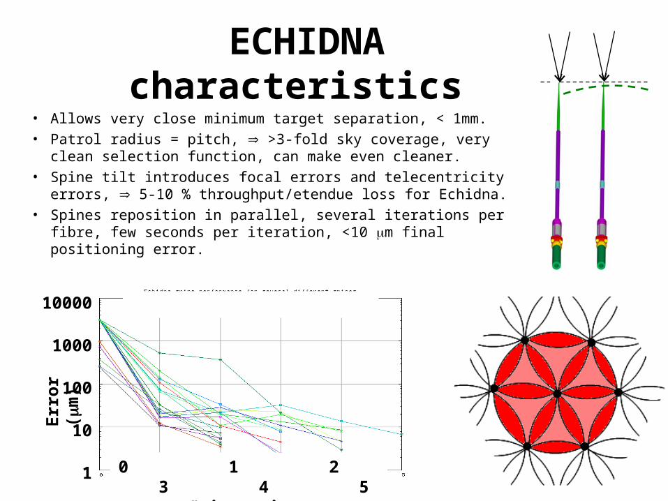
ECHIDNA characteristics• Allows very close minimum target separation, < 1mm.• Patrol radius = pitch, >3-fold sky coverage, very clean
selection function, can make even cleaner.• Spine tilt introduces focal errors and telecentricity errors, 5-
10 % throughput/etendue loss for Echidna.• Spines reposition in parallel, several iterations per fibre, few
seconds per iteration, <10 m final positioning error.
Erro
r m
10000
1000
100
10
1 0 1 2 3 4 5 # iterations
Err
or
(m
)

Echidna in operation

Mohawk for DESpec
Magnet and cup (pole piece)
Counter-weight
Bearing ball
Piezoceramic tube
Carbon fibre tube
Fibre ferrule Fibre
• Mohawk design for DESpec has 4000 fibers in hexagonal layout, pitch 6.0mm, 450mm focal surface, curved with 8m ROC.
• Spine design continuously developed and simplified since Echidna. Now just 7 parts per actuator, mostly off-the shelf.
• Low cost, low risk, simple, modular and proven design.
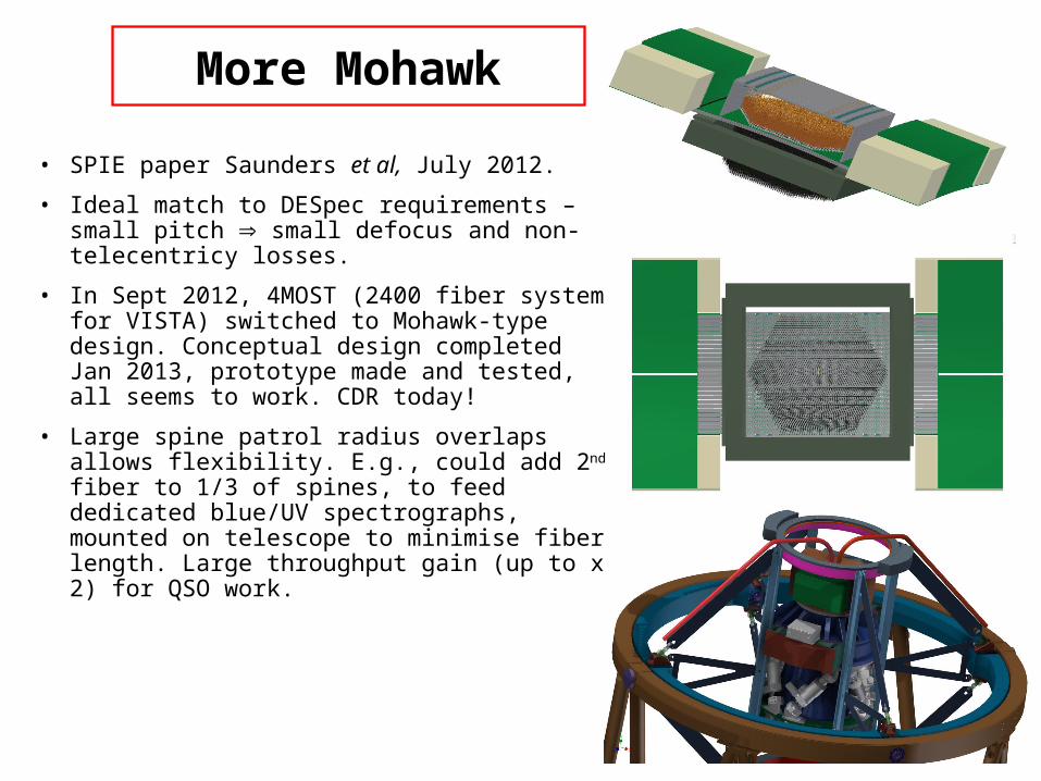
More Mohawk
• SPIE paper Saunders et al, July 2012.
• Ideal match to DESpec requirements – small pitch small defocus and non-telecentricy losses.
• In Sept 2012, 4MOST (2400 fiber system for VISTA) switched to Mohawk-type design. Conceptual design completed Jan 2013, prototype made and tested, all seems to work. CDR today!
• Large spine patrol radius overlaps allows flexibility. E.g., could add 2nd fiber to 1/3 of spines, to feed dedicated blue/UV spectrographs, mounted on telescope to minimise fiber length. Large throughput gain (up to x 2) for QSO work.

Positioning Video
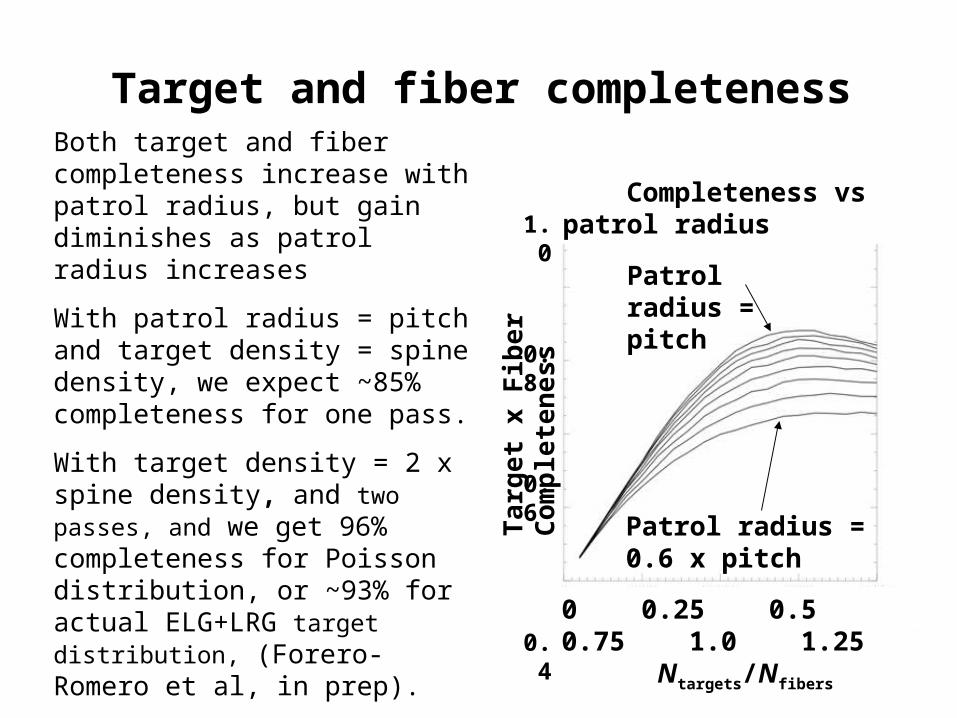
Target and fiber completenessBoth target and fiber completeness increase with patrol radius, but gain diminishes as patrol radius increases
With patrol radius = pitch and target density = spine density, we expect ~85% completeness for one pass.
With target density = 2 x spine density, and two passes, and we get 96% completeness for Poisson distribution, or ~93% for actual ELG+LRG target distribution, (Forero-Romero et al, in prep).
Leaves 7% fibers for sky, perfect.0 0.25 0.5 0.75 1.0 1.25 Ntargets/Nfibers
Patrol radius = pitch
1.0
0.8
0.6
0.4
0.2
0
Targ
et x
Fib
er C
ompl
eten
ess
Completeness vs patrol radius
Patrol radius = 0.6 x pitch
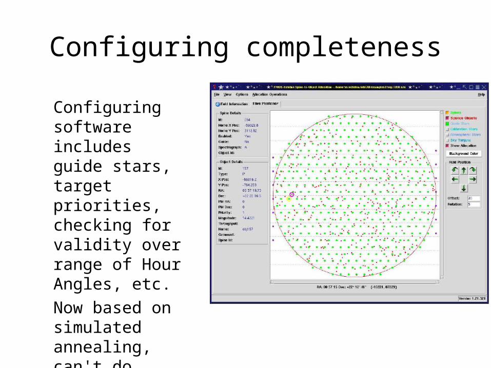
Configuring completeness
Configuring software includes guide stars, target priorities, checking for validity over range of Hour Angles, etc.Now based on simulated annealing, can't do better!

Configuring completeness
Configuring software includes guide stars, target priorities, checking for validity over range of Hour Angles, etc.Now based on simulated annealing, can't do better!

0 .05 0 .10 0 .15 0 .20 0 .25
0 .2
0 .4
0 .6
0 .8
1 .0
0 .05 0 .10 0 .15 0 .20 0 .25
0 .2
0 .4
0 .6
0 .8
1 .0Focal Ratio Degradation
Telescope beamCollimator speedGeometric FRDFiber FRDNet FRD
NABigBOSS
• FRD means loss of etendue, and penalties in throughput, resolution and/or cost.
• All fiber systems have ‘fiber FRD’ due to departures from cylindrical geometry.
• Fiber FRD is less with faster beams, strongly so in terms of etendue loss.
• Fiber FRD is less in larger fibers, but this does not fully compensate at fixed A. TBC!
• Small Mohawk pitch allows fast beam in the fiber, minimising ‘fiber FRD’.
• But spine tilt causes additional ‘geometric FRD’, due to non-telecentricity.
Even at maximum tilt, Mohawk has essentially identical etendue loss to BigBOSS design.
FRD vs speed, Edelstein et al SPIE 2012
f/4.8 f/3.6 f/2.9
MohawkNA
Inte
nsi
ty

Defocus
• Spine tilt also introduces up to 90m change in focus, causing increased aperture losses.
• Throughput effect is smaller than tilt losses.• We will set focus near maximum spine tilt,
so the spines with greatest tilt losses have the smallest defocus losses.
• Greatest throughput loss due to defocus is 2.6%
• Net additional throughput loss due to spine tilt and defocus combined, for faintest ELGs/LRGs and collimator, is just 2-3 %.
0 .2 0 .4 0 .6 0 .8 1 .0radiu spitch0 .005
0 .010
0 .015
0 .020
0 .025
0 .030
Los s

Aperture losses and fiber diameter
1 .61 .82 .02 .22 .4diam2 .02 .12 .22 .32 .4
t im e
1 .6 1 .7 1 .8 1 .9 2 .0Fibe r D iam
1 .01
1 .02
1 .03
1 .04
1 .05
Tim e
QSOs
ELGsLRGs
• Overall relative survey times have been determined, as a function of fiber size, for the main target samples.
• Includes seeing, galaxy profiles, air mass distribution (assumed same as SDSS), differential refraction, positioning errors.
• QSOs, ELG’s, LRGs all have optimal fiber size 1.7-1.8".
• With ADC, optimal fiber size for QSOs is smaller ~1.5".
• But minimum is extremely flat.
• 1.76" gives industry-standard 125m fibers, can use standard telco ferrules and connectors.
A 5000 fiber Mohawk positioner option for the Mayall?
• The Mohawk prototype has a pitch of 6.0mm at the focal surface.
• This would allow 5000 spines in a hexagonal array of diameter ~500mm, or 2.5 at the natural f/3 speed of the Mayall telescope.
• We have not identified any significant new design issues with this option.
• It would have 1300 fibers/deg2. A two-pass survey would give almost the same surface density of targets as a five-pass BigBOSS survey.
• Fiber and target completeness would be ~93%.
• QSO would get shorter total integrations, but large potential compensating gain from using shorter blue fibers.
• Positioner could have same ROC and mechanical interface as for DESpec, raising possibility of interchangeability with DECam, on both Blanco and Mayall telescopes. This would allow Dark Energy experiments in both North and South hemisperes.