module 3.5 - flowlines & risers
TRANSCRIPT

7/27/2019 Module 3.5 - Flowlines & Risers
http://slidepdf.com/reader/full/module-35-flowlines-risers 1/33
Subsea Systems Integration Course
Subsea Flowlines and Risers
Course Module – Subsea Flowlines and RisersModule 3.5
7/27/2019 Module 3.5 - Flowlines & Risers
http://slidepdf.com/reader/full/module-35-flowlines-risers 2/33
Subsea Systems Integration Course
Subsea Flowlines and Risers
Module Objective
• Objective:
Review the various designs and installation techniques available for
transporting hydrocarbons from the well to the host platform. Identify the
drivers for the flowline and riser designs. Explain the impact of different
design decisions on the subsea system.
• At the end of this session you will be able to:Identify the flowline and risers options
Define the design drivers and critical decisions for
flowline system selection
Recognize the ramification of the critical component
selection
7/27/2019 Module 3.5 - Flowlines & Risers
http://slidepdf.com/reader/full/module-35-flowlines-risers 3/33
Subsea Systems Integration Course
Subsea Flowlines and Risers
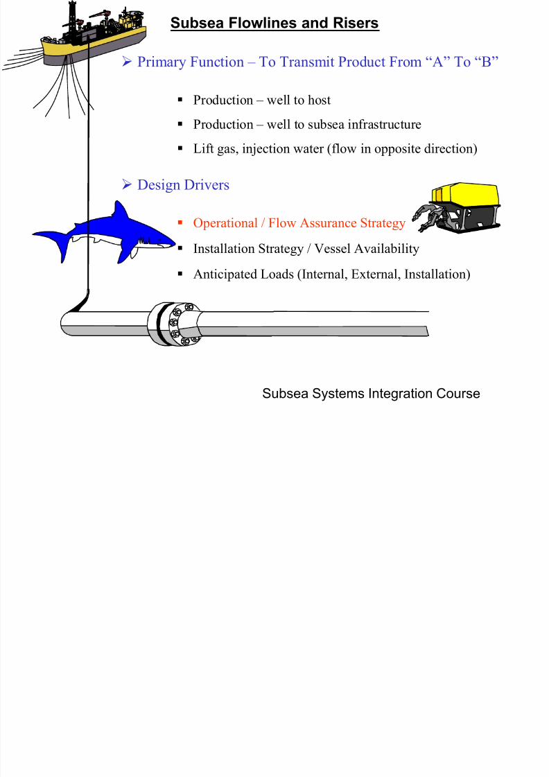
Primary Function – To Transmit Product From “A” To “B”
Production – well to host
Production – well to subsea infrastructure
Design Drivers
Operational / Flow Assurance Strategy
Installation Strategy / Vessel Availability
Lift gas, injection water (flow in opposite direction)
Anticipated Loads (Internal, External, Installation)

7/27/2019 Module 3.5 - Flowlines & Risers
http://slidepdf.com/reader/full/module-35-flowlines-risers 4/33Subsea Systems Integration Course
Subsea Flowlines and Risers
•Required Cooldown Time
•Required Arrival Temp.
•Wax Strategy•Erosion Potential
•Asphaltenes
•Hydrate Strategy
•Internal Corrosion
•External Corrosion
Thermal Retention
•Bare, Polymer Insulation,
Burial, Pipe-in-Pipe,
Bundled Pipe
Functional Architecture
•Single Lines, Looped or
Dual Line System, Riser
Type, Termination Type
Materials
•Carbon Steel, CRA, Liners,
Clad Pipe
Flow Assurance Drivers
Decisions

7/27/2019 Module 3.5 - Flowlines & Risers
http://slidepdf.com/reader/full/module-35-flowlines-risers 5/33Subsea Systems Integration Course
Subsea Flowlines and Risers Thermal Retention
Bare Pipe
Pipe-in-Pipe
•low CAPEX
•very installable
•no heat retention
•may exclude someinstallation methods
•highest installation
loads (top tension)
•may not be possible
to repair
•may require onshore
fabrication facilities
Corrosion Coating
Only
Polymer Insulated •must be qualified forwaterdepth
•weak link is the field
joints
•may limit installation
vessels
Low Density Insulation
Outer Pipe
Bulkheads and/or
Waterstops
BundlesInsulated Pipe•limited deepwater
burial systems
•may not work in all
soils
•requires
consolidation time
•not proven for
deepwater •requires onshore
infrastructure
•may not be possible
to repair
•long tows have a
history of problems
Insulated or Flooded Annulus
Service and Control
Lines
Outer Pipe
Flexibles•application limits for high
temp, high pressure,
chemical exposure
•prefabricated
Buried Pipe

7/27/2019 Module 3.5 - Flowlines & Risers
http://slidepdf.com/reader/full/module-35-flowlines-risers 6/33Subsea Systems Integration Course
Subsea Flowlines and Risers Thermal Retention
Electrical Heating
Methods
• Pipe-in-Pipe (skin effect)
• Single Pipe (return cable in close proximity)
• Bundled Single Pipe (return cable within the
bundle)
Applications
• Continuous – always providing heating
• Ever Ready – can be “turned on” at any time• Ready – hardware included subsea to allow
intervention spread to supply electrical power
“Current” Limitations
• Dry Terminations Only – there does not exist a
submerged, load bearing electrical isolation joint for
the riser
• Limited Access to Intervention Spread (EH Ready)
– Only one intervention spread exists, CAPEX costis high
EH Intervention
7/27/2019 Module 3.5 - Flowlines & Risers
http://slidepdf.com/reader/full/module-35-flowlines-risers 7/33
Subsea Systems Integration Course
Subsea Flowlines and Risers
$-
$100,000
$200,000
$300,000
$400,000
$500,000
$600,000
$700,000
2.0 12.0 22.0 32.0 42.0 52.0 62.0 72.0 82.0
Length (miles)
C
o s t p e r i n c h - d i a - m i l e
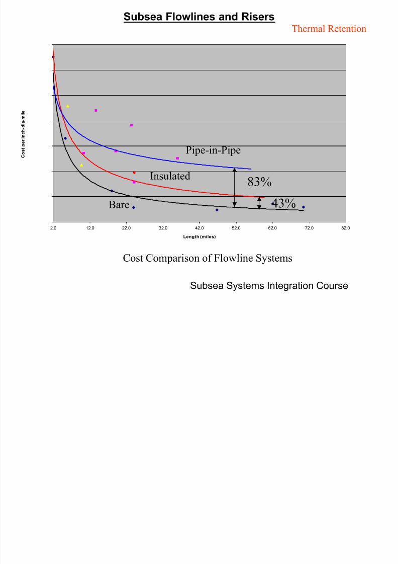
Pipe-in-Pipe
Insulated
Bare 43%
83%
Thermal Retention
Cost Comparison of Flowline Systems

7/27/2019 Module 3.5 - Flowlines & Risers
http://slidepdf.com/reader/full/module-35-flowlines-risers 8/33
Subsea Systems Integration Course
Subsea Flowlines and Risers Functional
Architecture
Components of the Flowline System
• Riser
• Terminations
• Flowline
Termination with Flowline Sled Preparation for Riser Hang-off

7/27/2019 Module 3.5 - Flowlines & Risers
http://slidepdf.com/reader/full/module-35-flowlines-risers 9/33
Subsea Systems Integration Course
Subsea Flowlines and Risers
Single Leg
Hybrid Risers
or Towers
J-Tube Risers
Clamped Risers
Near Vertical Risers (NVR)
& Steel Steepwave Risers (SSR)
Steel Catenary Riser (SCR)
Top TensionLazy Wave
Functional
Architecture

7/27/2019 Module 3.5 - Flowlines & Risers
http://slidepdf.com/reader/full/module-35-flowlines-risers 10/33
Subsea Systems Integration Course
Subsea Flowlines and Risers Functional
Architecture
Hubs – Flowpath Extension
Termination – Distribute Bending Stress and End Load
Mudmat – Resist Settlement
and MovementInstrumentation – Monitor
Flowpath Condition
Platform – ROV Parking
Hubs – Future Connections and
Injection Points
Valves – Isolation or Flow Direction
Installation AidsHinge – Reduce Installation Forces
Hook – Recovery, Rotation Resistance

7/27/2019 Module 3.5 - Flowlines & Risers
http://slidepdf.com/reader/full/module-35-flowlines-risers 11/33
Subsea Systems Integration Course
Subsea Flowlines and Risers
Daisy-ChainFlowline
System
Functional
Architecture
Dual
Flowline
System
Single
Flowline
System
•piggable
•can produce through single line
during late life, in the event of
damage, or during unique
activities such as expansion•dual sided blowdown capable
for hydrates
•allows segregation of
production (high pressure/low
pressure, well testing, etc.)
•approx. 30% less CAPEX
•piggable
•can produce through single line
during late life, in the event of
damage, or during unique
activities such as expansion•allows greater/optimum
spacing of wells
•allows limited segregation of
production (high pressure/low
pressure, well testing, etc.)

7/27/2019 Module 3.5 - Flowlines & Risers
http://slidepdf.com/reader/full/module-35-flowlines-risers 12/33
Subsea Systems Integration Course
Subsea Flowlines and RisersMaterialsOxygen
Carbon dioxide (“sweet”)
Bacteria
Hydrogen sulfide (“sour”) - can be ofbacterial origin
Acids (organic, inorganic) - can be ofbacterial origin
Low Alloy Carbon Steel (X-70 and less)
• non-corrosion resistant
Low Alloy Carbon Steel (high strength)
• hydrogen embrittlement
• welding Issues
• limited availabilityCRA Clad Carbon Steel
• welding Issues
• inspection Issues (NDE)
• manufacturing issues
• expensive, may be limited to critical areas
Solid CRA
• hydrogen embrittlement
• welding issues
• galvanic concerns with adjacent materials
Non-Metallic Linings
• field joints difficult
• may limit installation method
• bonding with pipe
Strategies
Use a corrosion allowanceRegular replacement
Coatings
Cathodic Protection Coating
Chemical protection
Maintenance, e.g. pigging
Use Corrosion Resistant Alloy (CRA)
Use Non-Metallic Material
Issues

7/27/2019 Module 3.5 - Flowlines & Risers
http://slidepdf.com/reader/full/module-35-flowlines-risers 13/33
Subsea Systems Integration Course
Subsea Flowlines and Risers
Primary Function – To Transmit Product From “A” To “B”
Production – well to host
Design Drivers
Operational / Flow Assurance Strategy
Installation Strategy / Vessel Availability
Production – well to subsea infrastructure
Lift gas, injection water (flow in opposite direction)
Anticipated Loads (Internal, External, Installation)

7/27/2019 Module 3.5 - Flowlines & Risers
http://slidepdf.com/reader/full/module-35-flowlines-risers 14/33
Subsea Systems Integration Course
Subsea Flowlines and Risers
Installation Drivers
Decisions
•Vessel Availability and
Cost
•Potential Conflict of
Activities or Access
•Vessel Capabilities
Lay Methods
•S-lay, J-lay, Reeled, Towed
System Components•Risers, Flowline System
Field Access
•First Ends Sleds, Second
Ends Sleds, Fixed PlatformRisers, Floating Host Risers

7/27/2019 Module 3.5 - Flowlines & Risers
http://slidepdf.com/reader/full/module-35-flowlines-risers 15/33
Subsea Systems Integration Course
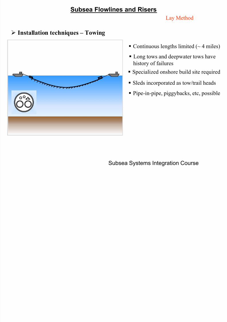
Subsea Flowlines and RisersLay Method
Installation techniques – S-Lay
Wide range of pipe diameters
Multiple welding stations
Deepwater limited by weight of span
and collapse on the stinger
Limitations on what can be passed
through the stinger (valves, sleds, etc.)
Typical lay rate = 2-4 miles/day

7/27/2019 Module 3.5 - Flowlines & Risers
http://slidepdf.com/reader/full/module-35-flowlines-risers 16/33
Subsea Systems Integration Course
Subsea Flowlines and RisersLay Method
Installation techniques – J-Lay
Wide range of pipe diameters
Limited number of welding stations
(typically one)
Lowest span weight, allowing
deepwater advantage
Not suited to piggyback lines, etc.
Typical lay rate = 1-2 miles/day
Double or Quad jointing of pipe
requires onshore fabrication facilities
Shallow water limitations
7/27/2019 Module 3.5 - Flowlines & Risers
http://slidepdf.com/reader/full/module-35-flowlines-risers 17/33
Subsea Systems Integration Course
Subsea Flowlines and Risers
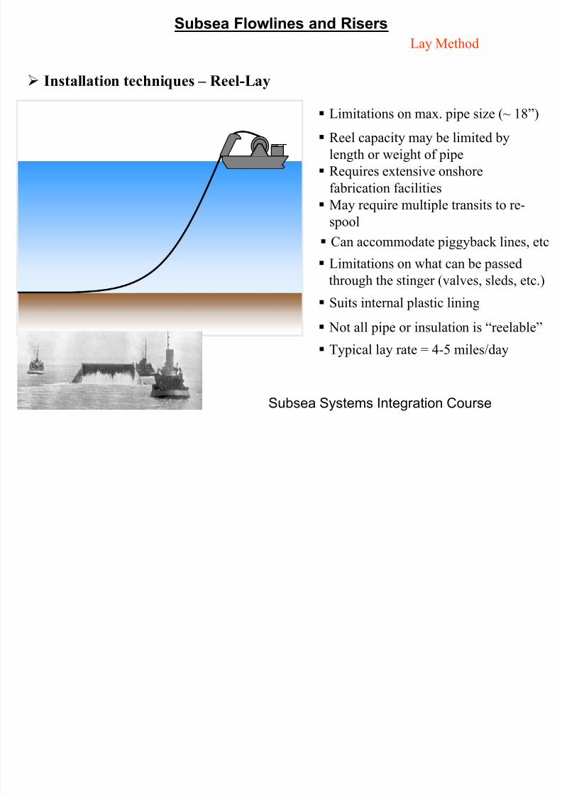
Lay Method
Installation techniques – Reel-Lay
Limitations on max. pipe size (~ 18”)
Reel capacity may be limited by
length or weight of pipe
Requires extensive onshore
fabrication facilities
May require multiple transits to re-
spool Can accommodate piggyback lines, etc
Suits internal plastic lining
Limitations on what can be passed
through the stinger (valves, sleds, etc.)
Not all pipe or insulation is “reelable”
Typical lay rate = 4-5 miles/day
7/27/2019 Module 3.5 - Flowlines & Risers
http://slidepdf.com/reader/full/module-35-flowlines-risers 18/33
Subsea Systems Integration Course
Subsea Flowlines and Risers
Lay Method
Installation techniques – Towing
Continuous lengths limited (~ 4 miles)
Long tows and deepwater tows have
history of failures
Specialized onshore build site required
Pipe-in-pipe, piggybacks, etc, possible
Sleds incorporated as tow/trail heads
S b Fl li d Ri

7/27/2019 Module 3.5 - Flowlines & Risers
http://slidepdf.com/reader/full/module-35-flowlines-risers 19/33
Subsea Systems Integration Course
Subsea Flowlines and Risers
System Components
J-Tube Risers
• Limited inspection capabilities (inside tube)
• J-tubes must be pre-installed
• Quick, cost effective installation
• Pull forces may be high
Clamped Risers
• Requires diving operations
• Riser is exposed to potential impact damage
S b Fl li d Ri

7/27/2019 Module 3.5 - Flowlines & Risers
http://slidepdf.com/reader/full/module-35-flowlines-risers 20/33
Subsea Systems Integration Course
Subsea Flowlines and Risers
Single Leg Hybrid Risers or Towers
• Installation independent of the host
• Minor host loading
• Allows wells located close to the host
Near Vertical Risers• Allows well located close to the host
• Medium host loading
Steel Catenary Risers
• High host loading
• Inexpensive
• Not buoyancy dependent
• Well must be far from host
Lazy Wave Risers
• Medium host loading
• Wells must be far from host
System Components
S b Fl li d Ri

7/27/2019 Module 3.5 - Flowlines & Risers
http://slidepdf.com/reader/full/module-35-flowlines-risers 21/33
Subsea Systems Integration Course
Subsea Flowlines and Risers
Subsea Flowlines and Risers

7/27/2019 Module 3.5 - Flowlines & Risers
http://slidepdf.com/reader/full/module-35-flowlines-risers 22/33
Subsea Systems Integration Course
Subsea Flowlines and Risers
Field Access
Abandonment Cable
Laydown AreaLay Vessel
Installation Strategy must includeaccess to the field and should consider:
• conflicts between floating assets
• conflicts with mooring cables and abandonment cables
• station keeping capabilities proximity of floating assets
Subsea Flowlines and Risers Fi ld A

7/27/2019 Module 3.5 - Flowlines & Risers
http://slidepdf.com/reader/full/module-35-flowlines-risers 23/33
Subsea Systems Integration Course
Subsea Flowlines and Risers Field Access
TowedReeledJ-layS-lay
Clear Accessrequired
Clear AccessRequired
Clear AccessRequired
Clear AccessRequired
SecondEnd at
Rig
Clear Accessrequired
Pull-in fromrig mounted
winch;seafloor sheave
required
Pull-in fromrig mounted
winch;seafloor sheave
required
Pull-in fromrig mounted
winch;seafloor sheave
required
First Endat Rig
With orwithout thehost; subsea
tie-in
Clear Accessrequired
Pull-in withhost mounted
winch/jack
Requires useof slack loop
Lay Past andSweep, Stalk
Riser
SecondEnd atHost
With orwithout thehost; subsea
tie-in
Pull-in withhost mountedwinch/jack,sheave onseafloor
If host is notpresent,
holdbackanchor
initiation
Pull from Host(or Vessel)
Bow-StringInitiation,
Stalk Riser;holdback
anchorinitiation
First Endat Host
HybridTopTension
SCR J-tubeClamped
Riser/Sled Lay Method
Difficult or
Rig/Host cannot be present
Only under
specific circumstancesUnmarked are
Unrestricted with
planning
Subsea Flowlines and Risers

7/27/2019 Module 3.5 - Flowlines & Risers
http://slidepdf.com/reader/full/module-35-flowlines-risers 24/33
Subsea Systems Integration Course
Subsea Flowlines and Risers
Primary Function – To Transmit Product From “A” To “B”
Production – well to host
Production – well to subsea infrastructure
Design Drivers
Operational / Flow Assurance Strategy
Installation Strategy / Vessel Availability
Anticipated Loads (Internal, External, Installation)
Lift gas, injection water (flow in opposite direction)
Subsea Flowlines and Risers

7/27/2019 Module 3.5 - Flowlines & Risers
http://slidepdf.com/reader/full/module-35-flowlines-risers 25/33
Subsea Systems Integration Course
Subsea Flowlines and Risers
Loading Drivers Decisions
• Internal Pipe Loads
• External Pipe Loads
• Installation Loads
Pipe Design
• Maximum Pressure,
Operational Allowances,
Design Criteria
Environmental Conditions
• Route Selection,
Hydrostatic Collapse, Spans,
Riser Fatigue
Installation and
Operational Loads
• Selection of Design
Criteria, Vessel Limitations
Subsea Flowlines and Risers

7/27/2019 Module 3.5 - Flowlines & Risers
http://slidepdf.com/reader/full/module-35-flowlines-risers 26/33
Subsea Systems Integration Course
Subsea Flowlines and Risers
Pipe DesignWall Thickness =
Operating Pressure Containment
+ Shut-In Tubing Pressure
+ Internal Corrosion Allowance
+ Internal Erosion Allowance
+ Mechanical Loss Allowance
+ On-Bottom Stability
+ Span Fatigue
+ Collapse Resistance
+ Thermal Buckling Resistance
Installation Early Life Mid Life Late Life
Early Life Mid Life Late Life
Early Life Mid Life Late Life
Early Life Mid Life Late Life
Early Life Mid Life Late Life
Early Life Mid Life Late Life
Early Life Mid Life Late Life
Early Life Mid Life Late Life
Early Life Mid Life Late Life
P r i m
a r y
I m p
a c t
Life of the Flowline System
Subsea Flowlines and Risers

7/27/2019 Module 3.5 - Flowlines & Risers
http://slidepdf.com/reader/full/module-35-flowlines-risers 27/33
Subsea Systems Integration Course
Subsea Flowlines and Risers
Subsea Flowlines and Risersi

7/27/2019 Module 3.5 - Flowlines & Risers
http://slidepdf.com/reader/full/module-35-flowlines-risers 28/33
Subsea Systems Integration Course
Subsea Flowlines and RisersEnvironment
Stability
Faults
Shallow Hazards
Slopes
Host
Well
Subsea Flowlines and RisersE i

7/27/2019 Module 3.5 - Flowlines & Risers
http://slidepdf.com/reader/full/module-35-flowlines-risers 29/33
Subsea Systems Integration Course
Subsea Flowlines and RisersEnvironment
Axial Load
Current
Overbend Strain on Stinger
Touchdown Fatigue
Sagbend Strain
Construction Fatigue
Axial Load
Vortex Inducted VibrationVortex Inducted Vibration
Collapse and Propagation
Thermal GrowthCurrent Spans
Impact
Roller Impact Load
Subsea Flowlines and Risers
7/27/2019 Module 3.5 - Flowlines & Risers
http://slidepdf.com/reader/full/module-35-flowlines-risers 30/33
Subsea Systems Integration Course
CAUTIONS
Subsea Flowlines and Risers

7/27/2019 Module 3.5 - Flowlines & Risers
http://slidepdf.com/reader/full/module-35-flowlines-risers 31/33
Subsea Systems Integration Course
EXTREMELY ROBUST WILL LIKELY JUST
FAIL IN A NEW WAY
Subsea Flowlines and Risers

7/27/2019 Module 3.5 - Flowlines & Risers
http://slidepdf.com/reader/full/module-35-flowlines-risers 32/33
Subsea Systems Integration Course
Too good to be true,
probably is too goodto be true.
Qualification is
critical.
Subsea Flowlines and Risers
7/27/2019 Module 3.5 - Flowlines & Risers
http://slidepdf.com/reader/full/module-35-flowlines-risers 33/33
Subsea Systems Integration Course
Module Objective
• Objective:
Review the various designs and installation techniques available for
transporting hydrocarbons from the well to the host platform. Identify the
drivers for the flowline and riser designs. Explain the impact of differentdesign decisions on the subsea system.
• At the end of this session you will be able to:
Identify the flowline and risers options
Define the critical decisions for flowline system selection
Recognize the ramification of the critical component
selection