module 2 lectures 6 to 12 high speed wind tunnels nozzles ...nptel.ac.in/courses/101106040/chapter...
TRANSCRIPT

Experimental Aero(Gas) dynamics Prof. Job Kurian
Chapter-2
Dept. of Aerospace Engg., Indian Institute of Technology, Madras 1
Module 2 Lectures 6 to 12
High Speed Wind Tunnels
Keywords: Blow down wind tunnels, Indraft wind tunnels, supersonic wind tunnels, c-d
nozzles, second throat diffuser, shocks, condensation in wind tunnels, and liquefaction in
wind tunnels.
2.0 High speed wind tunnels
2.1 Types of high speed tunnels
2.2 Supersonic wind tunnels
2.2.1 Test section flow parameters
Dynamic pressure
Mass flow rate
Test section velocity
Maximum velocity
Free stream reynolds number
2.3 Components of supersonic wind tunnels
Air storage tanks
Settling chamber /wide angle diffusers
Convergent-divergent (c-d) nozzle
Diffuser
2.4 Power required for the operation of supersonic wind tunnels
2.5 Closed circuit supersonic wind tunnel
2.6 Actual flow in the supersonic wind tunnel
2.6.1 Starting the wind tunnel with the model in the test section
2.6.2 Sizing the wind tunnel model
2.6.3 Two problems in the operation of the supersonic wind tunnel
(i) Condensation
(ii) Liquefaction

Experimental Aero(Gas) dynamics Prof. Job Kurian
Chapter-2
Dept. of Aerospace Engg., Indian Institute of Technology, Madras 2
High speed wind tunnels
2.0 Definition of high speed
When compressibility effects are pre dominant the flow is generally said to be of high speed.
A lower limit is approximately M=0.5. Power requirements vary as cube of velocity in the
wind tunnel. This does not hold into the high speed regime exactly. Because of large power
requirements, high speed wind tunnels are of the intermittent type.
2.1 Types of high speed wind tunnels
1. Continuous (for all speed ranges)
2. Intermittent
2.1 Blowdown (Fig 2.1)
M > 0.5 < 5.0
2.2 Indraft (Fig 2.2)
2.3 Intermittent pressure vacuum tunnel for M>5
Fig.2.1 Pressure driven blow down supersonic wind tunnel

Experimental Aero(Gas) dynamics Prof. Job Kurian
Chapter-2
Dept. of Aerospace Engg., Indian Institute of Technology, Madras 3
Fig 2.2 Indraft type wind tunnel
Table 2.1 Comparison between Indraft and Pressure driven wind tunnels
Indraft wind tunnels Pressure driven wind tunnels
Stagnation temperature at supply
condition is constant during a run.
So also is total pressure. No fluctuations
as those generated by a pressure
regulator.
Reynolds number can be varied at a
particular Mach no.
No possible contamination such as that
due to oil.
Cost is much less than of an indraft
tunnel.
Vacuum is safer to handle than pressure.
Pressure regulators are not needed.
The wind tunnels described above can be converted as continuous tunnels. The comparison
between blow down and continuous wind tunnels are as given in Table 2.2

Experimental Aero(Gas) dynamics Prof. Job Kurian
Chapter-2
Dept. of Aerospace Engg., Indian Institute of Technology, Madras 4
Table 2.2 Comparison between intermittent and continuous wind tunnels
Intermittent(blow down) wind tunnels Continuous wind tunnels
Simple to design and less costly
More in control of conditions and return
to a given test condition with more
accuracy.
A single drive may run several
Tunnels
Check points are easily obtained
No panic of rapid testing
Model testing is more convenient Test conditions can be held constant for
a longer time.
Extra power is available to start
Failure of model will not result in
tunnel damage
2.2 Supersonic wind tunnels
Introduction
The nozzle regulates the speed of air entering the test section (T.S) of the wind tunnel so that
the desired Mach number is established. Mach number is uniquely determined by the area ratio
of the nozzle. A well designed nozzle makes the flow parameters uniform across the cross
section. The design of a suitably shaped nozzle contour to obtain the desired uniform flow at
the nozzle exit is based on the method of characteristics.
2.2.1 Test section parameters
(i) Dynamic pressure
The local dynamic parameter 21ρv
2can be related to the local Mach number and static
pressure.

Experimental Aero(Gas) dynamics Prof. Job Kurian
Chapter-2
Dept. of Aerospace Engg., Indian Institute of Technology, Madras 5
2 21 1 pq = ρ v = v
2 2 RT
2 21 p 1= v = p M
2 RT 2
(ii) Mass flow rate
* * *m = ρvA = ρ a A
* represents choked conditions (M = 1)
*
*
m ρ Av A= *
A A A
* * * *
*
ρ A v A=
A A
Since, *
*
*
pρ =
RT and * * *v = a = RT
One has
* *
*
*
m p A= RT
A RT A
* *
*
p A=
R AT
Using equation for *
0
T
T and
*
0
p
p
and writing in terms of stagnation conditions,
20T -1= 1+ M
T 2
0
*
T -1 2 + -1 + 1= 1+ = =
T 2 2 2
When M = 1,
- 10p + 1
=p 2

Experimental Aero(Gas) dynamics Prof. Job Kurian
Chapter-2
Dept. of Aerospace Engg., Indian Institute of Technology, Madras 6
-1
*
0
1/2
0
2
+1pm A=
A R AT 2
-1
+1 *
2 -10
0
m p 2 A=
A R +1 AT
Mass flow density is expressed as a function of stagnation conditions and the area ratio.
For isentropic flow, *A is a constant and *
A
A is a unique function of local Mach number.
+1/2 -1
2
*
1
-11 + M
A 1 2=+ 1A M
2
+1
-2 -120
0
m p -1= M 1+ M
A R 2T
(iii) Test section velocity
V = a M
1
2
2
0
2
RT M=
-11+ M
2
(iv) Maximum velocity
2
p P 0
vc T + = c T
2
v is maximum when cpT = 0
p vc - c = R
p Vc /c =
p
p
cc - = R

Experimental Aero(Gas) dynamics Prof. Job Kurian
Chapter-2
Dept. of Aerospace Engg., Indian Institute of Technology, Madras 7
P Pc -c
= R
pc -1= R
p
Rc =
-1
2
max p 0v = 2c T
1
2
max 0
2 Rv = T
-1
The test section flow velocity v for a given stagnation temperature T0 approaches the maximum
value vmax at relatively low supersonic Mach numbers.
For example,
In the case of 0T = 300K
R = 287J/kgK
and a test section Mach number of 5.0, the ratio of v/vmax can be calculated to see that it is
equal to 0.913. This means at ordinary stagnation temperatures, the velocity in the test section
reaches 91% of the maximum possible velocity corresponding to the total energy of the fluid.
The stagnation temperature T0 rather than the Mach number which is important to attain high
velocities.
(v) Free stream Reynolds Number (Re)
ρvLRe =
μ
Experimental observation is that μ is independent of pressure in the range of 0.001 to 20
atmospheres.

Experimental Aero(Gas) dynamics Prof. Job Kurian
Chapter-2
Dept. of Aerospace Engg., Indian Institute of Technology, Madras 8
n
0 0
0
0 0
1
-1
0 0
μ T= for air n = 0.768
μ T
μ T +C T=
μ T+C T
C = 130
T=
T
If this relation is assumed then the free stream Re can be expressed as a function of M1, the T.S
Mach no and of the stagnation parameters. Reynolds no per unit length Re
L
ρ v= ρ,v ,μ
μ are
expressed in stagnation quantities as given below.
1-
2 -1
0
1-
-12
n
n
0 020
1
2
2
-1= 1+ M
2
-1= 1+ M
2
T 1μ = μ = μ
-1T 1+ M2
vM=
a
v = Ma
1= Ma
-11+ M
2

Experimental Aero(Gas) dynamics Prof. Job Kurian
Chapter-2
Dept. of Aerospace Engg., Indian Institute of Technology, Madras 9
2
2
0 0
a RT=
a RT
Re=
L
1 1--1 22
0
0n2
02
-11+ M
12* M a
-11+ M
21μ
-11+ M
2
n= 0.768 for air
Simplifying
10.268 -
-120
0
0
Re ρ -1= a M 1+ M
L μ 2
Both a0 and 0μ are functions of stagnation temperature. Both increase with temperature. Hence,
appreciable changes in free stream Re/unit length for a given M can be obtained only by
varying stagnation density.
2.3 Components of supersonic wind tunnels
2.3.1 Air storage tanks
Size of the storage will be dependent on the mass flows required and the frequency of runs.
Pressure storage tanks are available on the shelf basis – They are mounted horizontally or
vertically. Tanks are painted black to absorb heat. They are provided with safety disk or
pressure relief valve. As air is drawn from the storage, polytropic expansion takes place within
the tank. This results in drop of reservoir temperature which is very bothersome. Fall of
stagnation temperature causes resultant change in the stream temperature for a given Mach

Experimental Aero(Gas) dynamics Prof. Job Kurian
Chapter-2
Dept. of Aerospace Engg., Indian Institute of Technology, Madras 10
number. Change in temperature results in the change of viscosity which in turn affects the
boundary layer thickness. Changes in Reynolds number and Mach number during a run are
thus consequential to the fall in reservoir temperature.
To maintain constancy of stagnation temperature, it is a practice to stack the reservoir volume
with empty metallic cans. They serve as heat storing matrix during compression and release
heat during the expansion process. Another way to maintain the constant stagnation
temperature is by providing heater units in the reservoir.
2.3.2 Settling chamber /wide angle diffusers
Fig.2.3a, b Wide angle diffuser
Wide angle diffusers lead the flow to the settling chamber. Arrangements for leading the flow
to the settling chamber may be by one of the methods shown in Figure 2.3a, b or c.

Experimental Aero(Gas) dynamics Prof. Job Kurian
Chapter-2
Dept. of Aerospace Engg., Indian Institute of Technology, Madras 11
Fig.2.3c Reverse entry into the settling chamber
Uniformity of flow in the test section is improved if a large area ratio contraction is provided.
2.3.4 Convergent-divergent (c-d) nozzle
The c-d nozzle forms the heart of the supersonic wind tunnel .For generating supersonic flow
in the test section, it is essential that there is a c-d nozzle in the tunnel circuit before the test
section. The area ratio of the c-d nozzle (Aexit/Athroat) uniquely decides the Mach number.

Experimental Aero(Gas) dynamics Prof. Job Kurian
Chapter-2
Dept. of Aerospace Engg., Indian Institute of Technology, Madras 12
Fig.2.4 Convergent divergent nozzle and the pressure profile
When the tunnel operation starts, the flow is initiated in the nozzle as subsonic and reaches the
sonic Mach number at the throat when sufficient mass flow is allowed. This is called the
choked condition of the nozzle. Under this condition, maximum mass flow rate for the given
stagnation conditions takes place through the nozzle. The ratio between the upstream
stagnation pressure (P0) and the downstream back pressure (Pb) corresponding to the first time
choking is called the first critical pressure ratio of the nozzle. At this pressure ratio, the flow in
the divergent part of the nozzle is subsonic. The exit Mach number will be the subsonic value
corresponding to the A/A* in the Fig.2.5. In this context A is the exit area and A* the throat
area of the choked nozzle. As the value of P0/Pb is progressively increased, the flow in the
divergent part of the nozzle accelerates to be supersonic but shocks are formed in the divergent
part until a pressure ratio corresponding to the supersonic Mach number of the nozzle is
reached. The pressure ratio corresponding to this Mach number is the third critical pressure
ratio of the nozzle. Between the first and third critical pressure ratios shocks of varying
strengths take place in the nozzle and outside of it as there is no other isentropic solution
between the 1st and 3
rd critical pressure ratios. The pressure ratio corresponding to the
occurrence of a shock at the exit plane of the nozzle is the second critical pressure ratio of the
nozzle.

Experimental Aero(Gas) dynamics Prof. Job Kurian
Chapter-2
Dept. of Aerospace Engg., Indian Institute of Technology, Madras 13
Fig.2.5 A/A* vs. Mach numbers
All the shocks generated at the different pressure ratios inside the nozzle will make the post
shock Mach number subsonic and the subsonic nozzle exit pressure will be made equal to the
ambient pressure in the remaining part of the diffusing divergent channel. Between the second
and third critical pressure ratios, oblique shocks of varying strengths depending on the pressure
ratio will be formed emanating from the nozzle lip. The physical purpose of these oblique
shocks is equalization of pressures between the exit plane and the ambient. If the pressure ratio
is increased beyond that corresponding to the third critical pressure ratio, expansion fans will
be formed at the lip of the nozzle.

Experimental Aero(Gas) dynamics Prof. Job Kurian
Chapter-2
Dept. of Aerospace Engg., Indian Institute of Technology, Madras 14
2.3.5 Diffuser- the necessity of providing a diffuser
Fig.2.6 a Nozzle of a free jet facility
Take the case of a free jet facility as in Fig.2.6 making use of a c-d nozzle of Mach number 3.0
exiting to the ambient conditions at one atmosphere pressure. In order to avoid shocks and
expansion waves at the exit of the nozzle, pe must be pb.
o
e M = 3
p= 36.7
p
Pressure ratio required will be o
e
p= 36.7
p for a wave free exit flow from the nozzle.

Experimental Aero(Gas) dynamics Prof. Job Kurian
Chapter-2
Dept. of Aerospace Engg., Indian Institute of Technology, Madras 15
Fig.2.6 b Free jet nozzle with a test section
In the Figure 2.6b, a constant area section is added to the nozzle exit. The duct similar to the
test section (T.S) of a wind tunnel attached to the nozzle exhausts to atmosphere. ep
corresponds to static pressure at the exit plane of the nozzle before the shock. Static pressure
after the shock (p2) is equal to ambient pressure.
o o e
2 e 2
p p p 1= × = 36.7× = 3.55
p p p 10.33
In the equation above, pe/p2 represents the shock pressure ratio at M=3.0.
In the third case, as in Figure 2.8 a divergent channel is provided after the constant area duct
and the shock stands at the end of the constant area duct.
Fig.2.8 Free jet facility with test section and a diffuser

Experimental Aero(Gas) dynamics Prof. Job Kurian
Chapter-2
Dept. of Aerospace Engg., Indian Institute of Technology, Madras 16
When M << 1, op = p
0
o e 2
e 2 o2 M = 0.475
p p p p 1= = 36.7 × × 0.856
p p p p = p 10.33= 3.04
The three cases described above make it clear that provision of a diffuser of suitable design is
required for reducing the pressure ratio required for the operation of the wind tunnel. It is
shown in section 2.5 that the power required to run the wind tunnel increases with the pressure
ratio. In supersonic wind tunnels, most commonly used diffuser is of convergent divergent type
(also called the second throat diffuser).
2. 4 Power required for the operation of supersonic wind tunnel
Fig.2.9 Free jet type wind tunnel with an attached test section
Refer to figure 2.7 where a free jet type wind tunnel is shown. Let the supersonic tunnel is
specified by the Mach number (M) in the test section and test section (A) area .The throat area

Experimental Aero(Gas) dynamics Prof. Job Kurian
Chapter-2
Dept. of Aerospace Engg., Indian Institute of Technology, Madras 17
is specified as ANT. The flow parameters in the test section are denoted as p, T, A etc.. Once M
is specified, the area ratio AT/ANT and ratios of pressure and temperature p/p01 and T/T01 are all
known from the isentropic equations. If the compressor is idealized (isentropic) the suction and
reservoir conditions are related.
-1/
S S
01 01
T p=
T p
Where sandTSp represent pressure and temperature at the compressor suction. If the nozzle is
choked, the mass flow rate can be written as,
( +1)/2 -1
01NT
0
p2m = A
R +1 T
The power required to operate the compressor may be found as follows:
If the compressor is isentropic, the work per unit time may be found from the enthalpy
difference across the compressor.
01 sW = -m h -h
=
01 s
R-m T -T
-1 [ W = work / unit time in W or
Nm
S]
=
s 01
s
m RT T-1
-1 T
-1
s 01
s
RT p= -m -1
-1 p
-1 /sp
RTW = -m (r ) -1
-1
The pressure ratio 01
s
p
pis known as the operating pressure ratio and is denoted by rp

Experimental Aero(Gas) dynamics Prof. Job Kurian
Chapter-2
Dept. of Aerospace Engg., Indian Institute of Technology, Madras 18
The very large power required for the operation of a supersonic wind tunnel is attributed to
the large operating pressure ratio. If the wind tunnel is equipped with a suitably designed
diffuser and a closed circuit arrangement as shown in the next section, the stagnation pressure
of the diffused high velocity air can be made use of by the compressor and the effective
pressure ratio can be reduced.
2.5 Closed circuit supersonic wind tunnel
Fig.2.10 Continuous type supersonic wind tunnel
A convergent-divergent (c-d) diffuser is provided as shown in Fig.2.10. Only if the flow is
isentropic, the stagnation pressure regained in the receiver following the diffuser (p02) is equal
to that of the flow entering the nozzle (p01).
In that case, p02 = p01
Then, rp = 1, so that compressor does no work. In practical cases, because of entropy changes
p02 < p01 and rp > 1. If the entropy change is confined to the region between the two throats, the
diffuser throat area ADT must be larger than the nozzle throat area ANT. Diffuser throat area
must be large enough to accommodate the stagnation pressure loss of the strongest shock. A
cooler is included prior to the compressor because compressor work is proportional to the
intake temperature.

Experimental Aero(Gas) dynamics Prof. Job Kurian
Chapter-2
Dept. of Aerospace Engg., Indian Institute of Technology, Madras 19
The practical operation of the closed circuit wind tunnel may be explained as follows: As the
tunnel is started, flow through it begins as subsonic and as the pressure ratio is increased the
nozzle is choked. Further increase in the pressure ratio causes shock to be formed in the
divergent section. At a pressure ratio corresponding to second critical pressure ratio, shock is
formed at the exit plane of the nozzle which is same as the entry section to the test section.
The formation of shocks during the starting process gives rise to fall in stagnation pressure.
The total pressure after the shock is designated as p02. This necessitates that the diffuser throat
is designed larger as decided by the ratio p02/ p01. The ratio of diffuser throat area to the nozzle
throat is in the inverse ratio of total pressures given above.
02NT
DT 01
pA= < 1
A p
The ratio of areas for different test section Mach numbers calculated based on normal shock
losses is given in Fig.2.11. This makes sure that the starting shock passes through the diffuser
throat. The diffuser throat area calculated as above does not take in to account the non-
isentropy of frictional flows and only the shock losses are considered.
Fig.2.11 Ratio of diffuser throat and nozzle
throat for different test section Mach numbers

Experimental Aero(Gas) dynamics Prof. Job Kurian
Chapter-2
Dept. of Aerospace Engg., Indian Institute of Technology, Madras 20
Assuming a frictionless operation, the shock may assume any section in the constant area test
section. But, the effect of friction is to make the shock unstable in the constant area duct. The
shock that is generated during starting of the tunnel does not stay at the nozzle exit (entry to
test section) but is moved downstream by the effect of friction.
Fig.2.12 Shock movement from nozzle exit to diffuser
The starting pressure ratio minimum required to cater to the shock at the test section Mach
number is corresponding to that for locating the shock at the nozzle exit. (worst shock)
01
0
ps
2 worst shock
pr
p
As the starting pressure ratio is maintained, the starting shock which moves down stream can
be stable only at an area equal to that of the test section. In the convergent part of the diffuser
the Mach number will be less than that in the test section. With the value of starting pressure
ratio which produced the shock at the test section Mach number being maintained, shock
losses at that Mach number is being catered to. Hence the starting shock stabilizes only in the
diverging part of the diffuser at a section where there is equal area and Mach number as the test
section. The starting shock crossing the diffuser throat and remaining in its divergent part is
called the ‘swallowing of the starting shock’.
It has to be remembered that as the diffuser throat is larger than the nozzle throat, the Mach
number there will be more than one but less than that in the test section. After the brief
Experimental Aero(Gas) dynamics Prof. Job Kurian
Chapter-2
Dept. of Aerospace Engg., Indian Institute of Technology, Madras 21
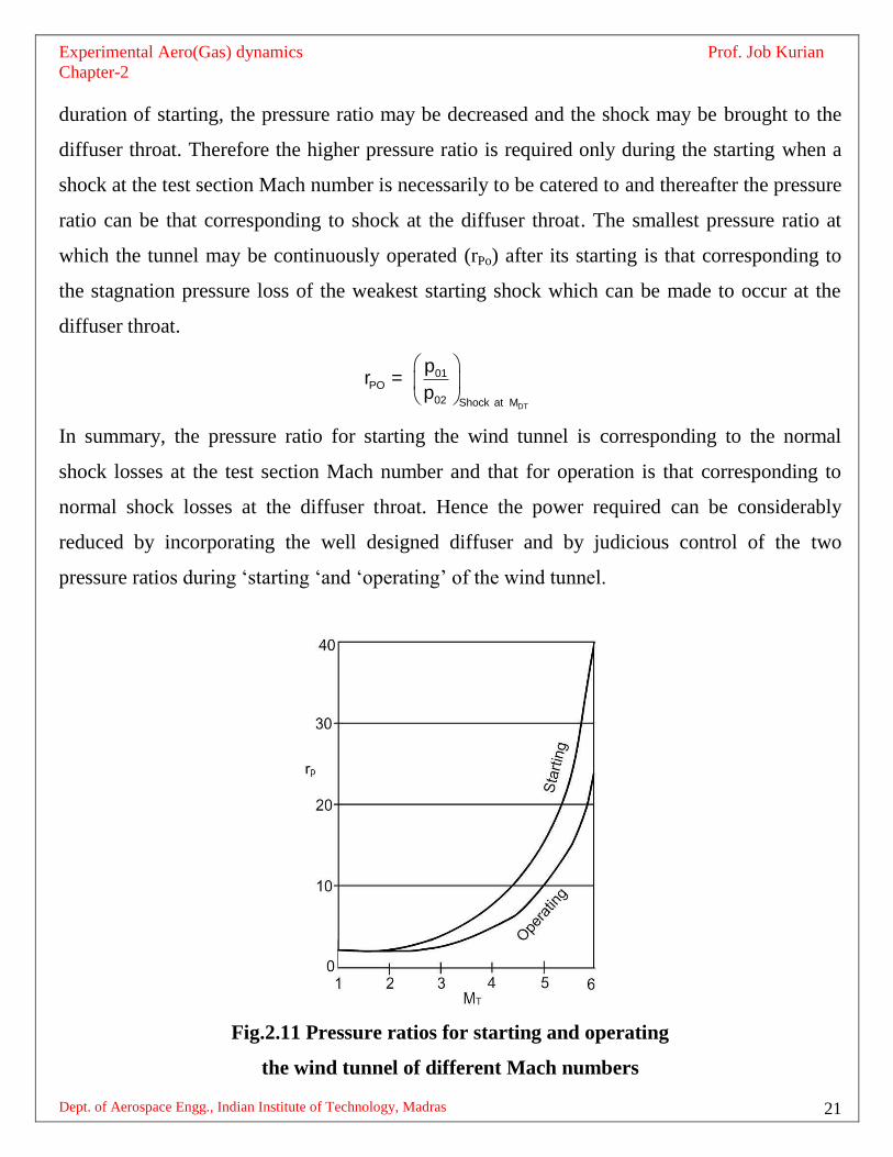
duration of starting, the pressure ratio may be decreased and the shock may be brought to the
diffuser throat. Therefore the higher pressure ratio is required only during the starting when a
shock at the test section Mach number is necessarily to be catered to and thereafter the pressure
ratio can be that corresponding to shock at the diffuser throat. The smallest pressure ratio at
which the tunnel may be continuously operated (rPo) after its starting is that corresponding to
the stagnation pressure loss of the weakest starting shock which can be made to occur at the
diffuser throat.
DT
01PO
02 Shock at M
pr =
p
In summary, the pressure ratio for starting the wind tunnel is corresponding to the normal
shock losses at the test section Mach number and that for operation is that corresponding to
normal shock losses at the diffuser throat. Hence the power required can be considerably
reduced by incorporating the well designed diffuser and by judicious control of the two
pressure ratios during ‘starting ‘and ‘operating’ of the wind tunnel.
Fig.2.11 Pressure ratios for starting and operating
the wind tunnel of different Mach numbers

Experimental Aero(Gas) dynamics Prof. Job Kurian
Chapter-2
Dept. of Aerospace Engg., Indian Institute of Technology, Madras 22
2.6 Actual flow in the supersonic wind tunnel
The boundary layer (B.L) thickness and the total loss of momentum increase with increasing
distance from the 1st throat. The growth of boundary layer thickness with distance from first
throat is predictable and can be accounted for in the nozzle design. In the steady state
operation, viscous effects between the throat and test section are not of much importance.
During the transient process in which tunnel is started, viscous effects are much important. So,
important are these effects that pressure ratios required to start high Mach number tunnels are
atleast 100% greater than the normal shock pressure ratio 01
02
p
p i.e. viscous losses are almost
equal to normal shock losses.
B.L. is stable when the pressure is decreasing in the direction of its growth. When the pressure
is increasing in the direction of flow, it has a tendency to separate. As normal shock passes
through the nozzle, it imposes a severe unfavorable pressure gradient which can cause
separation. If B.L separates, it disturbs the flow over a large portion of nozzle. If B.L. does not
separate the high pressure gain in the downstream of shock will tend to flow to low pressure
B.L. and the flow in the duct will be altered over a significant length of the nozzle. In the
diffuser viscous effects are predominant during starting and steady state operation of the wind
tunnel. Unfavorable pressure gradient exists always. An oblique shock from the convergence
creates additional pressure gradients when they strike the opposite wall.
2.6.1 Starting a tunnel with a model in the test section
It is explained earlier that
01DT
NT 02
pA=
A p

Experimental Aero(Gas) dynamics Prof. Job Kurian
Chapter-2
Dept. of Aerospace Engg., Indian Institute of Technology, Madras 23
which implies that losses in total head resulting from shocks necessitate a larger diffuser throat.
Hence, losses due to shocks on the model must also be provided for. So, for starting a tunnel
with a model, a second throat larger than that for a clear tunnel is needed.
2.6.2 Sizing the wind tunnel model
The theoretical unobstructed cross section area of the test section at the model required for
starting is the same as the second throat area.
Fig.2.12 Typical shock wave pattern from a model
In choosing the dimensions of the model, reflection of shocks should be also considered. The
oblique shocks formed as shown in Figure 2.12 at the leading edge of the model get reflected
from the wind tunnel wall. It has to be remembered that shock reflection is not specular which
means that the angle of incidence of the shock at the test section wall is not same as that for
reflection. The chord length of the model is so chosen that the reflected shocks do not interfere
with the model.
2.6.3 Two problems in the operation of supersonic wind tunnels
(i) Condensation
The amount of moisture that can be held by a unit volume of air increases with increasing
temperature. When the air isentropically expands to higher Mach numbers in the test section,
the temperature falls. It may become super cooled. Moisture will then condense.

Experimental Aero(Gas) dynamics Prof. Job Kurian
Chapter-2
Dept. of Aerospace Engg., Indian Institute of Technology, Madras 24
Factors affecting condensation
a) Amount of moisture in the stream
b) Static temperature of the stream
c) Static pressure of the stream
d) Time during which the stream is at low temperature
Effects of condensation
Condensation results in changes of local Mach number and other flow properties due to latent
heat addition. The extent of changes depends on how much heat is released through
condensation and may be evaluated using the two equations given below:
2 2
2 2
dM 1+ M dQ dA= -
M H A-M
2
2
dp M dQ dA= - -
p 1-M H A
The notations used in the equations are:
dQ = heat added through condensation
H = enthalpy per unit mass
A = duct area
When M > 1, Mach no decreases and pressure increases.
When M < 1, Mach no increases and pressure decreases.
Drying the working fluid is the best way to avoid condensation. Increasing the temperature by
providing stagnation heaters is another solution.

Experimental Aero(Gas) dynamics Prof. Job Kurian
Chapter-2
Dept. of Aerospace Engg., Indian Institute of Technology, Madras 25
(ii) Liquefaction
In a manner parallel to condensation, the components of air liquefy when proper temperature
and pressure conditions are met. Liquefaction troubles might start around M=4 if high pressure
air is expanded from room temperature.
Fig.2.13 Stagnation temperature to avoid
liquefaction at different Mach numbers
Fig.2.13 shows the stagnation temperature required to avoid liquefaction at different Mach
numbers. It can be seen that corresponding to a Mach number above 12 the temperature
required will be about 2000K.
*****************************************

Experimental Aero(Gas) dynamics Prof. Job Kurian
Chapter-2
Dept. of Aerospace Engg., Indian Institute of Technology, Madras 26
Exercises
Answer the following
1. Compare and contrast pressure storage and indraft wind tunnels
2. Why are air storage vessels of supersonic wind tunnels stacked with empty metallic
cans?
3. How justified are the stagnation pressure measurements being done in the settling
chamber of the supersonic wind tunnels?
4. What decides the exit Mach number of a c-d nozzle?
5. What is understood by the term ‘choking’ in c-d nozzles?
6. How to decide the exit Mach number of a c-d nozzle before it is choked?
7. Is there any change in the flow through the c-d nozzle if the stagnation pressure is
increased after the nozzle is choked?
8. Define the three critical pressure ratios of the c-d nozzle.
9. Explain the flow in the c-d nozzle of the supersonic wind tunnel between the 1st and
2nd
critical pressure ratios.
10. Justify the provision of a diffuser for a blow down wind tunnel.
11. Why the diffuser of a supersonic wind tunnel converging-diverging?
12. How to arrive at the dimensions of the second throat diffuser vis-a vis the nozzle
dimensions.
13. Derive the expression for the power required for the operation of a supersonic wind
tunnel in terms of the operating pressure ratio.
14. Differentiate between the ‘starting’ and ‘operating’ pressure ratios of the supersonic
wind tunnel provided with a second throat diffuser.
15. What factors decide the condensation in supersonic wind tunnels?
16. How can condensation be avoided/reduced in supersonic wind tunnels?
17. What is meant by liquefaction in supersonic wind tunnels?

Experimental Aero(Gas) dynamics Prof. Job Kurian
Chapter-2
Dept. of Aerospace Engg., Indian Institute of Technology, Madras 27
Work out the following numerical problems
Problem 1
Part I
In a supersonic wind tunnel of the following configuration, it is desired to simulate a flow
of Mach number ,M = 3.0, p = 0.680bar in a cross section of 30cm2 by taking compressor
supply from 1bar and 300C.Determine the resultant test section temperature and the power
required to operate the wind tunnel.
Part 2
For the wind tunnel given in Part I, in order to convert it to a continuous flow facility, a
diffuser is provided so proportional that it will barely swallow the starting shock. For identical
flow conditions as in Part I, find the size of the nozzle and diffuser throats and the power
required to (i) start and (ii) operate the wind tunnel.
Problem 2
A two dimensional double wedge airfoil of semi wedge angle 8.00
is placed at zero angle of
attack in a Mach 3.0 supersonic wind tunnel. What should be the minimum height of the wind
tunnel test section in terms of the chord so that the reflections of the oblique shock formed at
the leading edge of the model does not disturb the model.
*********************