module 2: customer water meters - american water … content... · module 2: customer water meters...
TRANSCRIPT
1
Copyright © 2009 American Water Works Association
AWWA eLearningDistribution Service to Customers
Module 2: Customer Water Meters
Types of Customer Water MetersAlmost all public water systems meter the water used by each service
connection or customer. The principal reason is to determine billing charges. A secondary reason is to track water use to ensure that there is no undue waste or leakage in the distribution system. In addition, when customers are billed for the exact amount of water used, they have an incentive to use water wisely.
Positive-Displacement MetersThe most common type of meter for measuring water use through
customer services is the positive-displacement meter. This type of meter consists of a measuring chamber of known size that measures the volume of water flowing through it by means of a moving piston or disk. The movement of each oscillation of the piston or disk is then transmitted to the register to record the amount of water. There are two types of positive-displacement meters: the piston type and the nutating-disk type.
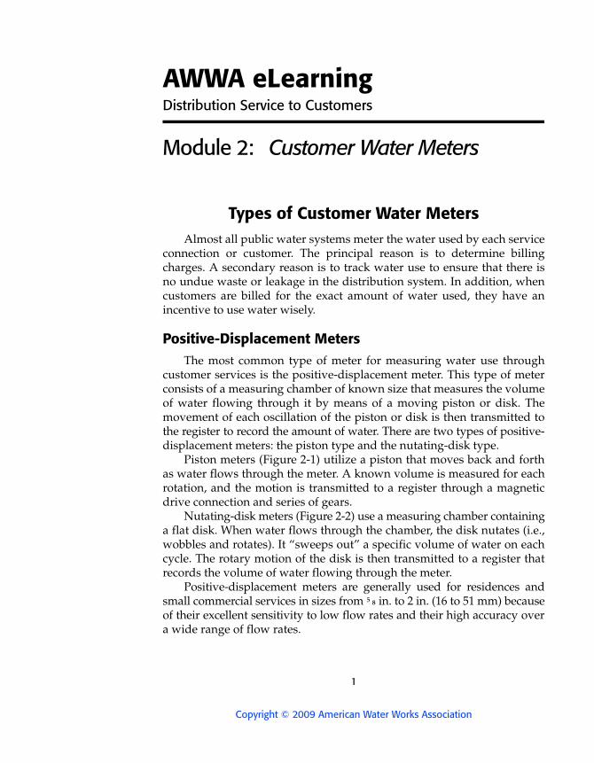
Piston meters (Figure 2-1) utilize a piston that moves back and forth as water flows through the meter. A known volume is measured for each rotation, and the motion is transmitted to a register through a magnetic drive connection and series of gears.
Nutating-disk meters (Figure 2-2) use a measuring chamber containing a flat disk. When water flows through the chamber, the disk nutates (i.e., wobbles and rotates). It “sweeps out” a specific volume of water on each cycle. The rotary motion of the disk is then transmitted to a register that records the volume of water flowing through the meter.
Positive-displacement meters are generally used for residences and small commercial services in sizes from ⁵ ₈ in. to 2 in. (16 to 51 mm) because of their excellent sensitivity to low flow rates and their high accuracy over a wide range of flow rates.
AWWA eLearning CUSTOMER WATER METERS 2
Copyright © 2009 American Water Works Association
FIGURE 2-1 Piston meter
Courtesy of ABB Water Meters
FIGURE 2-2 Nutating-disk meter with a plastic housing
Courtesy of Schlumberger Industries Water Division

AWWA eLearning CUSTOMER WATER METERS 3
Copyright © 2009 American Water Works Association
Positive-displacement meters under-register when they are excessively worn. To avoid excessive wear, they should not be operated in excess of the flow rates listed in Table 2-1. Continuous operation of a meter at maximum flow will quickly destroy it. A meter is generally sized so that its expected maximum rate will be one-half of its safe maximum operating capacity.
Large-Customer Meters Examples of customers that use large quantities of water are hospitals,
golf courses, large public buildings, apartment houses, and industries. Industries that always use a large amount of water are those that must do a great deal of cleaning and those that incorporate water into their manu-factured products. The types of meters most often used for large customersare compound meters, current meters, and detector-check meters.
Compound Meters
Compound meters are usually used for large customers that have wide variations in water use. There may be some times of the day when their water demand is very high and other times when there is little or no use. The meters furnished for these customers must be relatively accurate at both low and high flow rates.
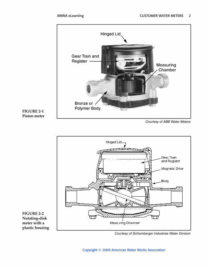
A standard compound meter consists of three parts: a turbine meter, a positive-displacement meter, and an automatic valve arrangement, all incorporated into one body (Figure 2-3). The automatic valve opens when high flows are sensed, enabling the water to flow with little restriction
TABLE 2-1 Maximum flow rates for positive-displacement meters
Meter Size,in. (mm)
Safe MaximumOperating Capacity,
gpm (L/s)
Recommended MaximumRate of Continuous
Operations,gpm (L/s)
¹ ₂ (15) 15 (0.95) 7.5 (0.47)¹ ₂ × ³ ₄
(15 × 20) 15 (0.95) 7.5 (0.47)
⁵ ₈ (17) 20 (1.3) 10 (0.63)⁵⁄₈ × ³ ₄
(17 × 20) 20 (1.3) 10 (0.63)
³ ₄ (20) 30 (1.9) 15 (0.95)1 (25) 50 (3.2) 25 (1.6)1¹ ₂ (40) 100 (6.3) 50 (3.2)2 (50) 160 (10) 80 (5.0)
Source: Adapted from AWWA Standards for Cold-Water Meters–Displacement Type, Bronze Main Case (1990).
AWWA eLearning CUSTOMER WATER METERS 4
Copyright © 2009 American Water Works Association
through the turbine side of the meter. Under low flows, the valve shuts and directs water through a small displacement meter for measurement. The unit therefore combines the favorable characteristics of both turbine and displacement meters into one unit. Compound meters may have separate registers for each meter, or their output can be combined to indi-cate total use on a single register.
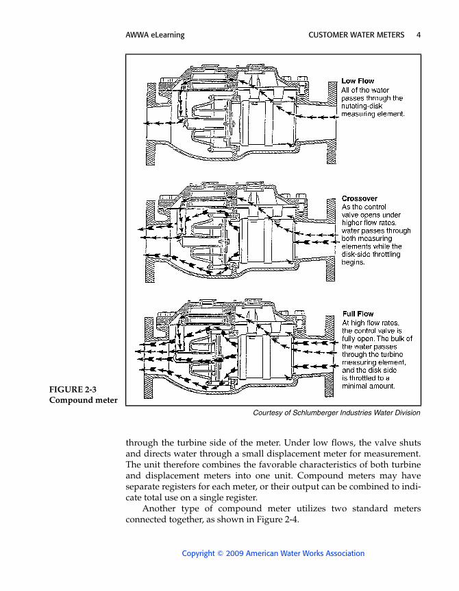
Another type of compound meter utilizes two standard meters connected together, as shown in Figure 2-4.
FIGURE 2-3 Compound meter
Courtesy of Schlumberger Industries Water Division
AWWA eLearning CUSTOMER WATER METERS 5
Copyright © 2009 American Water Works Association
Current Meters
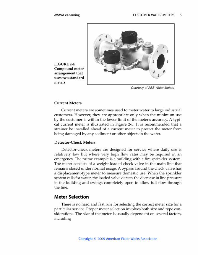
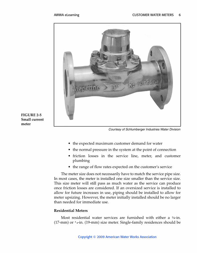
Current meters are sometimes used to meter water to large industrial customers. However, they are appropriate only when the minimum use by the customer is within the lower limit of the meter's accuracy. A typi-cal current meter is illustrated in Figure 2-5. It is recommended that a strainer be installed ahead of a current meter to protect the meter from being damaged by any sediment or other objects in the water.
Detector-Check Meters
Detector-check meters are designed for service where daily use is relatively low but where very high flow rates may be required in an emergency. The prime example is a building with a fire sprinkler system. The meter consists of a weight-loaded check valve in the main line that remains closed under normal usage. A bypass around the check valve has a displacement-type meter to measure domestic use. When the sprinkler system calls for water, the loaded valve detects the decrease in line pressurein the building and swings completely open to allow full flow through the line.
Meter SelectionThere is no hard and fast rule for selecting the correct meter size for a
particular service. Proper meter selection involves both size and type con-siderations. The size of the meter is usually dependent on several factors, including
FIGURE 2-4 Compound meter arrangement that uses two standard meters
Courtesy of ABB Water Meters
AWWA eLearning CUSTOMER WATER METERS 6
Copyright © 2009 American Water Works Association
• the expected maximum customer demand for water
• the normal pressure in the system at the point of connection
• friction losses in the service line, meter, and customer plumbing
• the range of flow rates expected on the customer's service
The meter size does not necessarily have to match the service pipe size. In most cases, the meter is installed one size smaller than the service size. This size meter will still pass as much water as the service can produceonce friction losses are considered. If an oversized service is installed to allow for future increases in use, piping should be installed to allow for meter upsizing. However, the meter initially installed should be no larger than needed for immediate use.
Residential Meters
Most residential water services are furnished with either a ⁵⁄₈-in. (17-mm) or ³ ₄-in. (19-mm) size meter. Single-family residences should be
FIGURE 2-5 Small current meter
Courtesy of Schlumberger Industries Water Division
AWWA eLearning CUSTOMER WATER METERS 7
Copyright © 2009 American Water Works Association
furnished with a larger meter only when there are a large number of plumbing fixtures. Usual practice is to start with a small meter. If the cus-tomer finds that flow is not adequate, a larger meter can be substituted.
Commercial Meters
Positive-displacement meters in sizes 1, 1¹ ₂, and 2 in. (19, 38, and 51 mm) are primarily used for apartment buildings, businesses, public buildings, and small industries. Buildings having flushometer toilets will usually require an above-average size meter in order to supply the extremely high rate of flow required if several toilets are flushed simul-taneously. Following are some general rules for commercial customer metering:
• If the meter will usually operate at 5 to 35 percent of the maximum rated capacity, and if accuracy at extremely low rates is not too important, then a displacement-type meter should be used.
• If close accuracy at very low flows is important, but if a large capacity is also needed, then the compound type will be the best choice. It will have lower pressure loss at high flow rates. However, a compound meter is considerably more expensive than a comparable displacement or turbine meter.
• If large capacity is of primary importance, normal flow is greater than 10 or 15 percent of the maximum rating, and low flow accuracy is secondary in importance, then the turbine type should be selected. Newer models, in particular, have very low pressure loss and maintain good accuracy over a wide range.
Customer Meter InstallationAs discussed in module 1, customer meters can be installed either in
outdoor meter pits or in the building being served. Installation of meters in basements is quite common. When there is no basement, some utilities will allow installation in a crawl space or a utility closet. Meter pits (or meter boxes) are usually located in the parkway, between the curb and sidewalk.
Large meters are often installed in precast concrete or concrete-block vaults if there is no appropriate location in a basement. Large meter installations are expensive and require considerable planning.
AWWA eLearning CUSTOMER WATER METERS 8
Copyright © 2009 American Water Works Association
General ConsiderationsIndoor installations are more common in northern states, where harsh
winter weather can cause frost damage to the meter and where houses are more likely to have basements. Outdoor installations are more common in warmer, more temperate climates. Whether the meter is installed indoors or out, there are several general requirements for acceptable installation.
• The meter should preferably not be subject to flooding with non-potable water.
• The installation should provide an upstream and a downstream shutoff valve to isolate the meter for repairs.
• The installation should position the meter in a horizontal plane for optimal performance.
• The meter should be reasonably accessible for service and inspection.
• The location should provide for easy reading either directly or via a remote reading device.
• The meter should be reasonably well protected against frost and mechanical damage.
• The meter installation should not be an obstacle or hazard to customer or public safety.
• The meter should have seals attached to the register to prevent tampering.
• There should be sufficient support for large meters to avoid placing stress on the pipe.
• A large installation should have a bypass or multiple meters so that water service does not have to be discontinued during meter replacement or repair.
Manifold InstallationsSome water systems commonly install two or three meters in a mani-
fold, or battery, for customers that require a high flow rate. As illustrated in Figure 2-6, a 4-in. (100-mm) service line can have three 2-in. (51-mm) displacement-type meters installed. Advantages of a battery installation include the following:
• Meters can be removed one at a time for servicing without disrupting customer service. This differs from a single large-meter installation, for which the customer is usually given free water through a bypass while the meter is being repaired.

AWWA eLearning CUSTOMER WATER METERS 9
Copyright © 2009 American Water Works Association
• Meters can be added and the system easily expanded if required.
• There is no need to buy or stock parts for several different size meters. All meters and valves are the same size.
• The battery can be mounted with the meters stacked along a basement sidewall to conserve floor space.
In a manifold unit with two or three meters, all but one of the meters must have a lightly loaded backpressure valve on their outlets. This way, when the flow is small, only one meter will operate. As flow increases, the backpressure valves open to permit flow through the other meters.
The price difference between a multiple-meter installation and a compound meter is another consideration. Older-model compound meters were very expensive, but newer models are now available that are more competitively priced.
In the past, commercial and industrial services were quite often metered with compound meters. These meters register well over a wide flow range and have a relatively low pressure loss at high flows. Today,
FIGURE 2-6 Manifold connection of three meters

AWWA eLearning CUSTOMER WATER METERS 10
Copyright © 2009 American Water Works Association
however, new types of horizontal turbine meters should be considered for these customers. They are quite sensitive to low flows, may have a lower initial cost, and may require less maintenance.
Meter ConnectionsThe types of connections used on water meters vary with the size of the
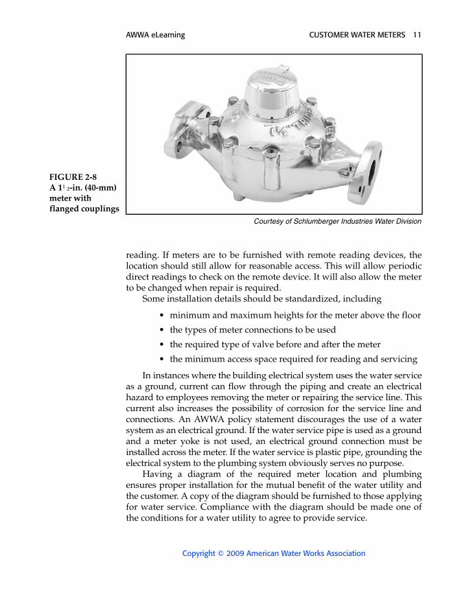
meter. Meter sizes up to 1 in. (25 mm) usually have screw-type connections(Figure 2-7), whereas larger meters usually have flanged connections (Figure 2-8).
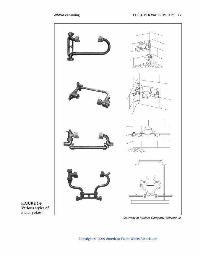
Many water utilities use a special device called a meter yoke or horn to simplify the installation of small meters. Figure 2-9 illustrates several types that are commonly used for both interior and meter-pit installa-tions. The purpose of a yoke is to hold the stub ends of the pipe in proper alignment and spacing to support the meter. Yokes also cushion the meter against stress and strain in the pipe and provide electrical continuity when metal pipe is used.
Indoor InstallationsMany water systems have developed a diagram illustrating how a
meter should be installed inside a building under normal circumstances. The meter should ideally be located immediately after the point where the service pipe enters through the floor or wall. If meters are to be read directly, the location must be kept relatively clear to allow convenient
FIGURE 2-7 A ³ ₄-in. (20-mm) meter with screw connections
Courtesy of Schlumberger Industries Water Division
AWWA eLearning CUSTOMER WATER METERS 11
Copyright © 2009 American Water Works Association
reading. If meters are to be furnished with remote reading devices, the location should still allow for reasonable access. This will allow periodic direct readings to check on the remote device. It will also allow the meter to be changed when repair is required.
Some installation details should be standardized, including
• minimum and maximum heights for the meter above the floor
• the types of meter connections to be used
• the required type of valve before and after the meter
• the minimum access space required for reading and servicing
In instances where the building electrical system uses the water service as a ground, current can flow through the piping and create an electrical hazard to employees removing the meter or repairing the service line. This current also increases the possibility of corrosion for the service line and connections. An AWWA policy statement discourages the use of a water system as an electrical ground. If the water service pipe is used as a ground and a meter yoke is not used, an electrical ground connection must be installed across the meter. If the water service is plastic pipe, grounding the electrical system to the plumbing system obviously serves no purpose.
Having a diagram of the required meter location and plumbing ensures proper installation for the mutual benefit of the water utility and the customer. A copy of the diagram should be furnished to those applying for water service. Compliance with the diagram should be made one of the conditions for a water utility to agree to provide service.
FIGURE 2-8 A 1¹ ₂-in. (40-mm) meter with flanged couplings
Courtesy of Schlumberger Industries Water Division
AWWA eLearning CUSTOMER WATER METERS 12
Copyright © 2009 American Water Works Association
FIGURE 2-9 Various styles of meter yokes
Courtesy of Mueller Company, Decatur, Ill.
AWWA eLearning CUSTOMER WATER METERS 13
Copyright © 2009 American Water Works Association
Outdoor InstallationsOutdoor meter installation varies depending on the size of the meter
involved.
Small-Meter Installation
Installing a small meter outdoors usually requires the use of a meter box or pit to protect the meter. Many factors influence the design, materials, installation details, and overall performance of an outdoor setting. Some of these factors are soil conditions, groundwater level, maximum frost penetration, and accessibility for reading and servicing.
The wide variations in ground frost penetration throughout the country make it impossible to detail a universally practical outdoor setting. As withthe indoor setting, a diagram should be prepared for use by water system employees, building inspectors, contractors, and homeowners. This diagram should illustrate a standard for meter pit location, construction, and plumbing. The meter pit is usually constructed and furnished by the owner's contractor. It is particularly important that the contractor be furnished with explicit instructions. Each community in an area often has completely different ideas on how the installation should be made. It is often hard for contractors to remember what each town desires. The following guidelines for the standard diagram should be observed:
• The meter pit should be located on public property if at all possible, but relatively close to the property line.
• The location should be relatively safe from being damaged by vehicles and snow-removal equipment.
• The lid of the pit or box should be tight fitting, tamper resistant, and placed flush with the ground surface so that it does not create a tripping hazard or interfere with lawn mowing.
• Where ground frost is expected, the riser pipes should be 1 to 2 in. (25 to 50 mm) away from any portion of the meter box walls to avoid freezing.
• The distance below ground surface at which the meter spuds or couplings are to be located must be specified. In general, small meters are raised to facilitate reading and meter replacement.
• The dimensions of the meter box to be used for each size meter must be specified.
• The location and type of curb stop or service control valve must be specified.
AWWA eLearning CUSTOMER WATER METERS 14
Copyright © 2009 American Water Works Association
• Use of a meter yoke is recommended for pit installation to make it easier to change the meter, and also to prevent distortion of the meter body due to pipe misalignment caused by shifting over a period of time.
Large-Meter Installation
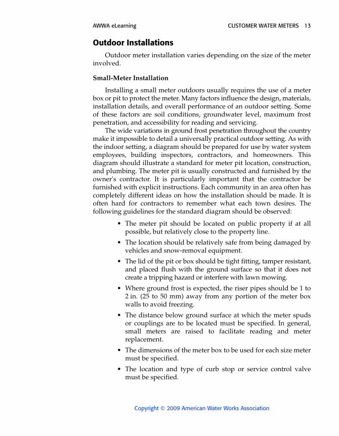
There is no uniform standard for large-meter installations. A prime consideration in the design is that large-meters are very heavy and require adequate support so that no stress is put on the service pipe. The cover on the meter pit must be made large enough for worker entry and meter removal.
Adequate work space must be allowed around large meters installed in a vault. At least 20 in. (510 mm) of clearance should be allowed to the vertical walls and at least 24 in. (610 mm) of head space from the highest point on the meter. More space is desirable. Test valves should be installed to permit volumetric tests. Provisions should be made for discharging the test water if meters are to be tested in place. The meter and valves should be supported, and thrust blocking should be provided when necessary. A typical large-meter installation is illustrated in Figure 2-10.
FIGURE 2-10 Large-meter installation diagram
Courtesy of Schlumberger Industries Water Division
AWWA eLearning CUSTOMER WATER METERS 15
Copyright © 2009 American Water Works Association
Valuable aid and installation recommendations can be obtained from meter manufacturers. These manufacturers can make recommendations on meter vault designs commonly used in the area, as well as on plumb-ing materials that will provide the most economical and satisfactory installation.
Meter ReadingMeters used in the United States are generally furnished with registers
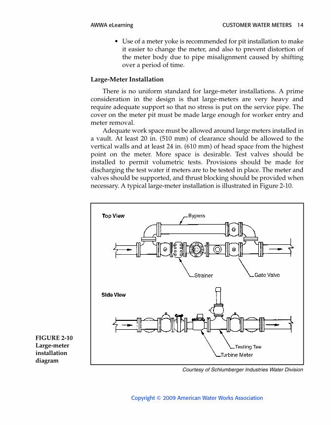
that record the flow of water in gallons or cubic feet. Registers that read in imperial gallons or cubic meters are also available. Water meter registers are usually of two types: circular or straight, as illustrated in Figure 2-11. Circular registers are somewhat difficult to read. They have gradually been replaced by straight registers on new meters. Straight registers are read like the odometer on a car. The meter reader simply reads the number indicated on the counting wheels, including any fixed zeros to the right of the counting wheel window.
The registers on large meters occasionally have a multiplier on them. If so, the multiplier will be noted on the meter or the register face, such as “10X” or “1,000X.” This marking indicates that the reader must multiply the reading by the multiplier in order to obtain the correct reading.
FIGURE 2-11 Meter registers
Courtesy of Schlumberger Industries Water Division
AWWA eLearning CUSTOMER WATER METERS 16
Copyright © 2009 American Water Works Association
Direct Meter ReadingTraditional meter reading involves a meter reader visiting each build-
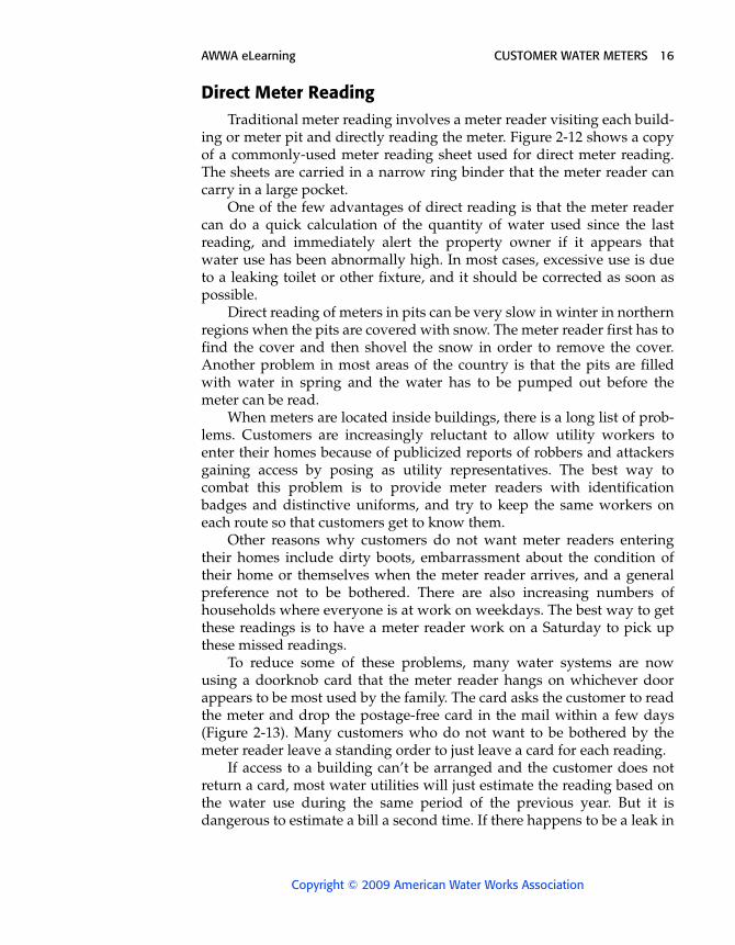
ing or meter pit and directly reading the meter. Figure 2-12 shows a copy of a commonly-used meter reading sheet used for direct meter reading. The sheets are carried in a narrow ring binder that the meter reader can carry in a large pocket.
One of the few advantages of direct reading is that the meter reader can do a quick calculation of the quantity of water used since the last reading, and immediately alert the property owner if it appears that water use has been abnormally high. In most cases, excessive use is due to a leaking toilet or other fixture, and it should be corrected as soon as possible.
Direct reading of meters in pits can be very slow in winter in northern regions when the pits are covered with snow. The meter reader first has to find the cover and then shovel the snow in order to remove the cover. Another problem in most areas of the country is that the pits are filled with water in spring and the water has to be pumped out before the meter can be read.
When meters are located inside buildings, there is a long list of prob-lems. Customers are increasingly reluctant to allow utility workers to enter their homes because of publicized reports of robbers and attackers gaining access by posing as utility representatives. The best way to combat this problem is to provide meter readers with identification badges and distinctive uniforms, and try to keep the same workers on each route so that customers get to know them.
Other reasons why customers do not want meter readers entering their homes include dirty boots, embarrassment about the condition of their home or themselves when the meter reader arrives, and a general preference not to be bothered. There are also increasing numbers of households where everyone is at work on weekdays. The best way to get these readings is to have a meter reader work on a Saturday to pick up these missed readings.
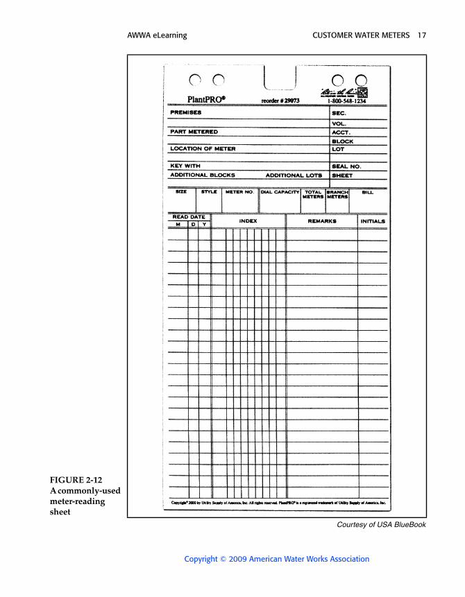
To reduce some of these problems, many water systems are now using a doorknob card that the meter reader hangs on whichever door appears to be most used by the family. The card asks the customer to read the meter and drop the postage-free card in the mail within a few days (Figure 2-13). Many customers who do not want to be bothered by the meter reader leave a standing order to just leave a card for each reading.
If access to a building can’t be arranged and the customer does not return a card, most water utilities will just estimate the reading based on the water use during the same period of the previous year. But it is dangerous to estimate a bill a second time. If there happens to be a leak in
AWWA eLearning CUSTOMER WATER METERS 17
Copyright © 2009 American Water Works Association
FIGURE 2-12 A commonly-used meter-reading sheet
Courtesy of USA BlueBook
AWWA eLearning CUSTOMER WATER METERS 18
Copyright © 2009 American Water Works Association
the house during the period of no actual readings for up to 9 months, the size of the water bill can be very substantial, and will surely result in a very irate customer.
Because of the time and labor involved in reading and billing, most utilities that are doing direct meter reading read and bill every three months (quarterly).
Remote Reading DevicesRemote reading devices were developed to eliminate most of the
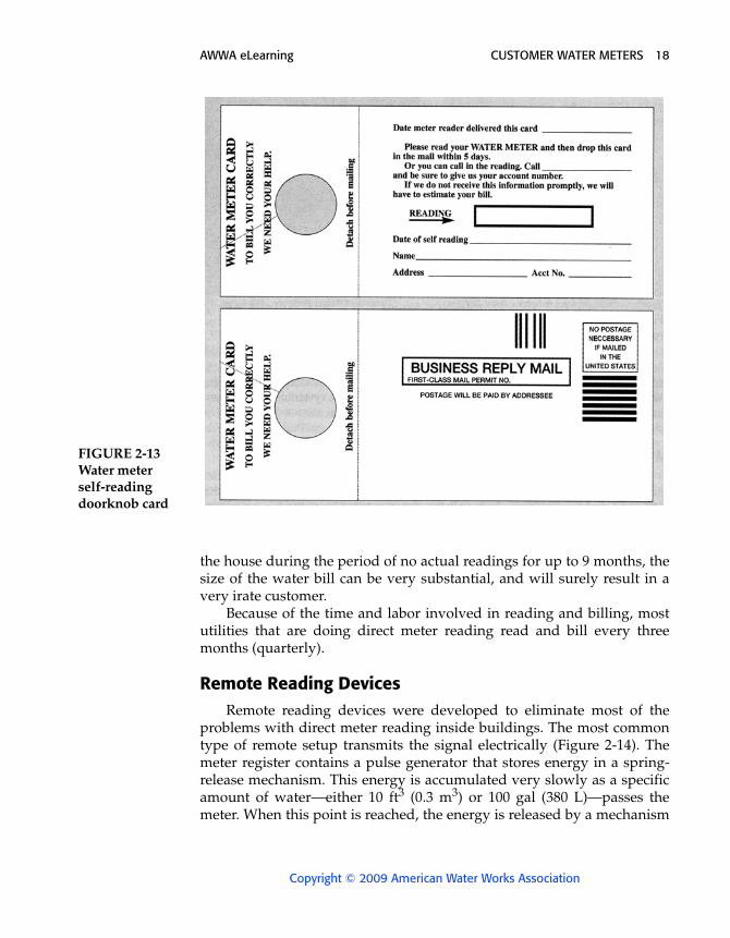
problems with direct meter reading inside buildings. The most common type of remote setup transmits the signal electrically (Figure 2-14). The meter register contains a pulse generator that stores energy in a spring-release mechanism. This energy is accumulated very slowly as a specific amount of water—either 10 ft3 (0.3 m3) or 100 gal (380 L)—passes the meter. When this point is reached, the energy is released by a mechanism
FIGURE 2-13 Water meter self-reading doorknob card
AWWA eLearning CUSTOMER WATER METERS 19
Copyright © 2009 American Water Works Association
that creates rapid motion between a permanent magnet and a copper coil. This motion generates an electric impulse that is transmitted through a two-conductor electric cable to the remote register mounted at a convenient location on the outside of the building. The remote register contains a counter that advances one digit for each pulse received.
Remote reading devices are quite popular in northern states where most meters are located inside. The use of remote registration has been increasing in areas where pit settings were more common, both in resi-dential and in commercial and industrial installations. In areas where large meters are installed under the street, it is often necessary to send a truck and a crew to direct traffic, manipulate pit entries, and then read the meters. However, conveniently located remote registers make it possible for one person to obtain these meter readings without disrupting traffic or risking personal injury.
When considering the installation of remote registration systems, the water supplier should make a thorough study of all the related factors. Much of this information is available on request from meter manufacturers, including
• comparisons of new meter setting costs with and without remote reading
• desirability and economics of retrofitting existing installations
FIGURE 2-14 Meter with remote register
Courtesy of Schlumberger Industries Water Division
AWWA eLearning CUSTOMER WATER METERS 20
Copyright © 2009 American Water Works Association
• interchangeability within meter models and brands used by the water supplier
• compatibility of the reading data obtained if both direct and remote systems are intermixed in the same route
• original equipment purchase price
• installation costs
• probable maintenance costs
• ultimate cost of obtaining and processing meter-reading data
Plug-in Type Readers
Several manufacturers also offer remote meter-reading units that have a plug-in receptacle. With this system, the reading is converted into an encoded electrical message within the meter head. This meter head is connected by a multiconductor cable to a receptacle located on an outside wall of the building. A meter reader can then plug a battery-operated reading device into the remote receptacle to take a reading. The meter reading may be visually displayed and also recorded for later direct entry into a computer.
Remote register or plug-in units are not as advantageous for meters in pits. They are sometimes mounted under the pit cover. Although the cover must be raised to make the reading, this approach is still easier than having a worker crawl into the pit to make a reading. The alternative is to find a protected spot near the pit where the register can be mounted aboveground, but this is rarely convenient.
Electronic Meter Reading
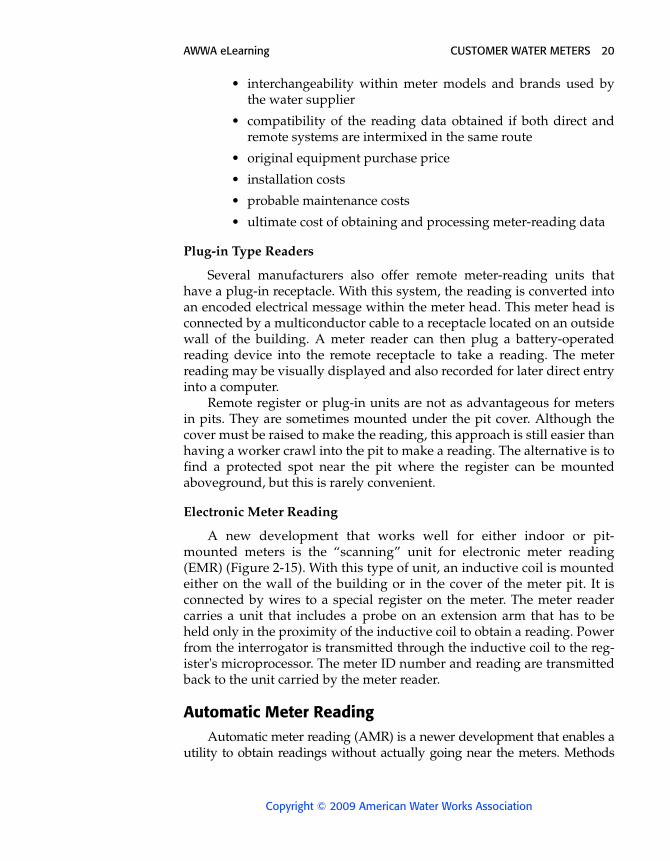
A new development that works well for either indoor or pit-mounted meters is the “scanning” unit for electronic meter reading (EMR) (Figure 2-15). With this type of unit, an inductive coil is mounted either on the wall of the building or in the cover of the meter pit. It is connected by wires to a special register on the meter. The meter reader carries a unit that includes a probe on an extension arm that has to be held only in the proximity of the inductive coil to obtain a reading. Power from the interrogator is transmitted through the inductive coil to the reg-ister's microprocessor. The meter ID number and reading are transmitted back to the unit carried by the meter reader.
Automatic Meter Reading Automatic meter reading (AMR) is a newer development that enables a
utility to obtain readings without actually going near the meters. Methods
AWWA eLearning CUSTOMER WATER METERS 21
Copyright © 2009 American Water Works Association
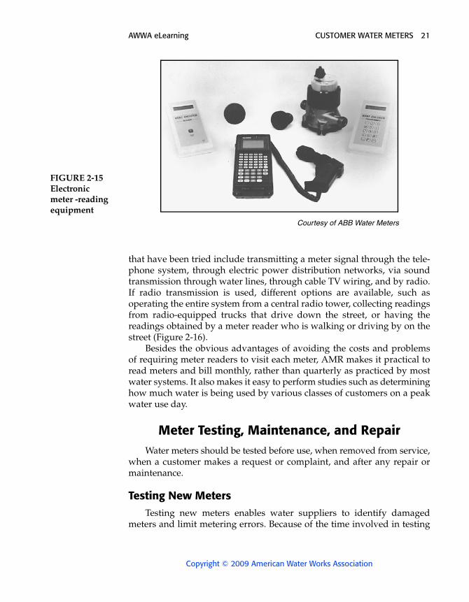
that have been tried include transmitting a meter signal through the tele-phone system, through electric power distribution networks, via sound transmission through water lines, through cable TV wiring, and by radio. If radio transmission is used, different options are available, such as operating the entire system from a central radio tower, collecting readings from radio-equipped trucks that drive down the street, or having the readings obtained by a meter reader who is walking or driving by on the street (Figure 2-16).
Besides the obvious advantages of avoiding the costs and problems of requiring meter readers to visit each meter, AMR makes it practical to read meters and bill monthly, rather than quarterly as practiced by most water systems. It also makes it easy to perform studies such as determininghow much water is being used by various classes of customers on a peak water use day.
Meter Testing, Maintenance, and RepairWater meters should be tested before use, when removed from service,
when a customer makes a request or complaint, and after any repair or maintenance.
Testing New MetersTesting new meters enables water suppliers to identify damaged
meters and limit metering errors. Because of the time involved in testing
FIGURE 2-15 Electronic meter -reading equipment
Courtesy of ABB Water Meters
AWWA eLearning CUSTOMER WATER METERS 22
Copyright © 2009 American Water Works Association
new meters, some state regulatory commissions have adopted regula-tions that allow a certain number of random meters in a shipment to be tested to determine the accuracy of the entire shipment. For example, if meters are shipped in boxes of 10, a water supplier might test only one random meter in that box. If that meter tests out accurately, all of the meters in the box can be assumed to be accurate. If the meter does not test out accurately, the water supplier would have to test all the other meters in the box or return all of them to the supplier for replacement. The state public utility regulatory commission should be consulted concerning any requirements it may have for testing new meters before use.
Frequency Requirements for Testing MetersWater meters are subject to wear and deterioration. The rate of wear
and deterioration is principally a function of how much the meter is used and the quality of the water. Over a period of time, meter efficiency decreases, and meters fail to start operating under low flow. Although some customers may sometimes think otherwise, meters very rarely over-register. Occasionally a customer insists on having an old meter replaced because he or she thinks it is running fast. The usual result is that the new meter will be more accurate, and the bill will be higher.
To avoid a loss of revenue for the utility, meters must either be field tested or brought in periodically for testing and repair. To help control
FIGURE 2-16 Wall mount, pit receptacles, and handheld computer for reading meters with a radio signal
Courtesy of Badgermeter Inc.
AWWA eLearning CUSTOMER WATER METERS 23
Copyright © 2009 American Water Works Association
meter deterioration and limit registration problems, many state regulatory commissions have adopted requirements for the frequency of meter test-ing. Because of the variability of water characteristics, the cost of testing, and water costs, a nationwide test frequency cannot be established. Most states with frequency requirements for meter testing base the test intervalson the size of the meter-the larger the meter, the more often it should be tested. AWWA recommends that ⁵⁄₈-in. (17-mm) meters be tested every 5 to 10 years.
Whether a water utility tests its own meters or has someone else do it depends on the staff size, time available, and facilities. Some utilities have the facilities to test all their meters, but the majority test only smaller meters. Larger meters may be field tested or sent to the manufacturer for testing. Smaller water systems do not usually have the facilities or the time to test meters, so they send the meters to the manufacturer or to a contractor for testing and repair. The economics of just disposing of old meters and purchasing new ones must also be considered.
Testing Procedures There are three basic elements to a meter test:
• running a number of different rates of flow over the operating range of the meter to determine overall meter efficiency
• passing known quantities of water through the meter at various test rates to provide a reasonable determination of meter registration
• meeting accuracy limits on different rates for acceptable use
The rates of flow generally used in testing positive-displacement meters are maximum, intermediate, and minimum. For current and com-pound meters, four or five flow rates are usually run. State regulations should be consulted to determine if specific rates are specified.
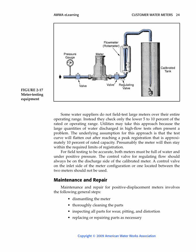
Equipment for meter testing does not have to be elaborate. A setup like the one shown in Figure 2-17 is suitable for small meters. It is generallymore economical to field-test large meters, especially current and compound types. Field testing is essentially the same as shop testing. The difference is that, instead of using a tank to measure the test water, opera-tors compare the meter to be tested and one that has previously been cali-brated. The two meters are connected in series, and the test water is discharged to waste. Since the calibrated meter is not 100 percent accurate at all flows, it is necessary to use a special calibration curve to adjust for different rates of flow in order to compute the accuracy of the meter being tested.
AWWA eLearning CUSTOMER WATER METERS 24
Copyright © 2009 American Water Works Association
Some water suppliers do not field-test large meters over their entire operating range. Instead they check only the lower 5 to 10 percent of the rated or operating range. Utilities may take this approach because the large quantities of water discharged in high-flow tests often present a problem. The underlying assumption for this approach is that the test curve will flatten out after reaching a peak registration that is approxi-mately 10 percent of rated capacity. Presumably the meter will then stay within the required limits of registration.
For field testing to be accurate, both meters must be full of water and under positive pressure. The control valve for regulating flow should always be on the discharge side of the calibrated meter. A control valve on the inlet side of the meter configuration or one located between the two meters should not be used.
Maintenance and RepairMaintenance and repair for positive-displacement meters involves
the following general steps:
• dismantling the meter
• thoroughly cleaning the parts
• inspecting all parts for wear, pitting, and distortion
• replacing or repairing parts as necessary
FIGURE 2-17 Meter-testing equipment
AWWA eLearning CUSTOMER WATER METERS 25
Copyright © 2009 American Water Works Association
• reassembling the meter
• retesting the meter
Maintenance and repair for other meters generally follow the same procedure, with some variations due to design differences.
Before undertaking a maintenance and repair program, water utilities should evaluate the cost-effectiveness of a meter replacement program versus a meter repair program. It is sometimes more economical simply to replace old parts with new parts or old meters with new meters, rather than to check tolerances, shim disks, or repair registers. Meter manufac-turers can furnish detailed repair instructions for each of their styles of meters.
Water RatesIn the United States, water rates are usually either expressed in dollars
per 1,000 gallons or dollars per 100 cubic feet, depending on which type of meter registration is used.
A minimum charge for each billing period is usually set up based on service or meter size. This is theoretically the water utility cost for main-taining staff and equipment, meter reading and billing, and other fixed costs, even if no water is used by the customer. The rate schedule used by water utilities generally falls into one of the following methods of bill computation:
• Flat rate — all customers pay the same rate per unit of water used, regardless of the amount of water use.
• Two-tiered, flat rate — customers are charged a minimum, plus a flat rate for water used.
• Pure declining block — the charge per unit of water declines in steps (or “blocks”), with increased water use. (This plan favors large customers such as industries)
• Two-tiered, declining block — an initial minimum charge covers a specified amount of water, then all use in excess of the minimum is charged at progressively lower rates.
• Pure increasing block — the charge per unit of water increaseswith increasing use (used by utilities where there is a water shortage)
• Two-tiered, increasing block — an initial minimum charge covers a specified quantity of water, then use in excess of this amount is charged at increasing rates
AWWA eLearning CUSTOMER WATER METERS 26
Copyright © 2009 American Water Works Association
Generally, if an adequate supply of water is available and water sys-tem facilities are adequate, a declining rate structure is used. If there is a limited amount of water available or system facilities are limited, no incentive for increased use may be offered. In some areas where there is a shortage of water, a disincentive is actually created by increasing the rates for increased used.
Customers with similar water use patterns are often grouped into rate classes such as residential, commercial, and industrial. There may be a different rate structure for each class based on when and how water is taken from the system. For instance, industrial customers who use the same amount of water year-round present some advantage in water system operation in comparison with residential customers who have wide swings in water use between winter and summer. Industries may at times also be given a preferential water rate to encourage them to settle or stay in the community.
When it is necessary for a water utility to make a significant change in the water rate, the amount of the new rate is usually arrived at by doing a rate analysis. This is a study that considers all factors to establish water rates as equitable as possible for all customers. One of the prime factors considered in the analysis is the value of all of the property and equip-ment owned by the water system. Records of expenditures and income and a bill analysis of water used by various classes of customers are also required. Much of the information required for a study can be gathered by water utility staff, but the actual analysis of the information is usually best done by a professional firm.
Small, publicly-owned water systems frequently do not maintain good property and operating expense records. When such a system wishes to perform a rate study, it is usually necessary to first employ a professional firm to make property appraisals and the expense estimates necessary to complete the rate analysis calculations.
■ ■■