modified direct torque control for single-phase induction ... · modified direct torque control for...
TRANSCRIPT
Modified Direct Torque Control for Single-phase Induction Motor Drives
THANATCHAI KULWORAWANICHPONG and TAWAT CHUCHIT Power System Research Unit
School of Electrical Engineering Suranaree University of Technology
111 University Avenue, Nakhon Ratchasima THAILAND
Abstract: - This paper illustrated a modified strategy of direct torque control for single-phase induction motors. The proposed strategy was based on classical six-sector hysteresis-type direct torque control scheme developed by using stator reference frame. The modification made in this paper led to two control strategies called modified six and twelve sectors, respectively. A switching table was derived based on the voltage vectors generated by the three-leg two-phase inverter topology. Simulations were carried out and performance analysis was presented. Key-Words: - Single-phase induction motor drives, Direct torque control, Hysteresis control, Six-sector based DTC, Twelve-sector based DTC 1 Introduction Three-phase induction motors have been increasingly important for industrial electric motor applications. It should note that there still exist DC motors in some limited applications, e.g. motors for vehicles. Apart from a large-size electric motor drive, single-phase induction motors are commonly used in household electric motor applications. These applications typically consume the power of a fractional horse power up to around ten horse powers. Although most electric appliances require a few amount of kilo-watt input, minimizing power losses during their operation gives a great benefit resulting in nationwide electric energy used by householders. In general, single-phase motors are controlled by a thyristor-phase controller or a variable resistor. This is quite simple, but it is not efficient in terms of energy consumption. To achieve this goal, complex control strategy cannot be avoid as long as ac machines are involved. One of widely-used control schemes is variable-voltage, variable-frequency (VVVF) [1]. It can be applied for motor control in many forms. However, this control strategy does not guarantee minimum loss operation. Therefore, adjustable frequency and voltage of the power supply is more flexible and can lead to more economical operation of household electric appliances. Over half a century, steady-state analysis of induction motors has become a powerful tool to characterize their performances [2-4]. It is fairly good in describing steady-state behaviors. For simple control where accuracy and precision are not that much important, any steady-state model is moderate. However, nowadays, a very accurate torque-speed control of induction motors via the space phasor theory, called vector control [5,6],
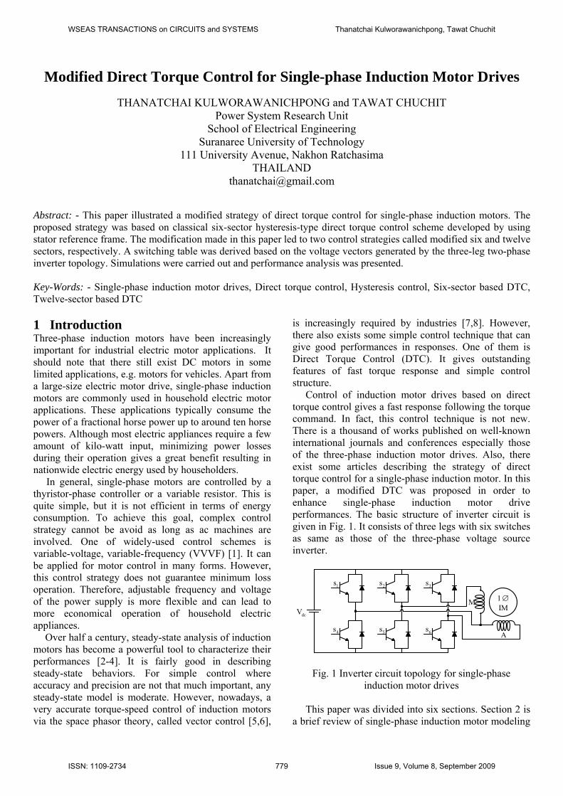
is increasingly required by industries [7,8]. However, there also exists some simple control technique that can give good performances in responses. One of them is Direct Torque Control (DTC). It gives outstanding features of fast torque response and simple control structure. Control of induction motor drives based on direct torque control gives a fast response following the torque command. In fact, this control technique is not new. There is a thousand of works published on well-known international journals and conferences especially those of the three-phase induction motor drives. Also, there exist some articles describing the strategy of direct torque control for a single-phase induction motor. In this paper, a modified DTC was proposed in order to enhance single-phase induction motor drive performances. The basic structure of inverter circuit is given in Fig. 1. It consists of three legs with six switches as same as those of the three-phase voltage source inverter.
2s 3s
6s5s
M
A
1 ∅IM
dcV
1s
4s
Fig. 1 Inverter circuit topology for single-phase induction motor drives
This paper was divided into six sections. Section 2 is a brief review of single-phase induction motor modeling
WSEAS TRANSACTIONS on CIRCUITS and SYSTEMS Thanatchai Kulworawanichpong, Tawat Chuchit
ISSN: 1109-2734 779 Issue 9, Volume 8, September 2009
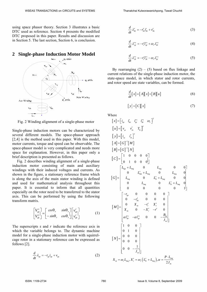
using space phasor theory. Section 3 illustrates a basic DTC used as reference. Section 4 presents the modified DTC proposed in this paper. Results and discussion are in Section 5. The last section, Section 6, is conclusion. 2 Single-phase Induction Motor Model
Fig. 2 Winding alignment of a single-phase motor
Single-phase induction motors can be characterized by several different models. The space-phasor approach [2,4] is the method used in this paper. With this model, motor currents, torque and speed can be observable. The space-phasor model is very complicated and needs more space for explanation. However, in this paper only a brief description is presented as follows. Fig. 2 describes winding alignment of a single-phase induction motor consisting of main and auxiliary windings with their induced voltages and currents. As shown in the figure, a stationary reference frame which is along the axis of the main stator winding is defined and used for mathematical analysis throughout this paper. It is essential to inform that all quantities especially on the rotor need to be transferred to the stator axis. This can be performed by using the following transform matrix.
⎥⎦
⎤⎢⎣
⎡⎥⎦
⎤⎢⎣
⎡θθ−θθ
=⎥⎦
⎤⎢⎣
⎡rdr
rqr
rr
rrs
dr
sqr
vv
VV
cossinsincos
(1)
The superscripts s and r indicate the reference axis in which the variable belongs to. The dynamic machine model for a single-phase induction motor with squirrel-cage rotor in a stationary reference can be expressed as follows [2].
qs qs qs qsd r i vdt
= − +λ (2)
ds ds ds dsd r i vdt
′ ′ ′ ′= − +λ (3)
s s s
qr r qr r drd r idt
′ ′ ′ ′= − +λ ω λ (4)
s s s
dr r dr r qrd r idt
′ ′ ′ ′= − −λ ω λ (5)
By rearranging (2) – (5) based on flux linkage and current relations of the single-phase induction motor, the state-space model, in which stator and rotor currents, and rotor speed are state variables, can be formed.
[ ] [ ][ ] [ ][ ]d x A x B udt
= + (6)
[ ] [ ][ ]y C x= (7)
Where [ ] Ts s
qs ds qr dr rx i i i i′ ′ ′⎡ ⎤= ⎣ ⎦ω
[ ] [ ]T
qs ds Lu v v T′=
[ ] [ ]T
qs dsy i i′=
[ ] [ ] [ ]1A G M−=
[ ] [ ] [ ]1B G N−=
[ ]1 0 0 0 0
0 1 0 0 0C =
⎡ ⎤⎢ ⎥⎣ ⎦
[ ]
0 0 00 0 0
0 0 00 0 00 0 0 0 1
lqs mq mq
lds mq mq
mq lr mq
mq lr mq
L L LL L L
G L L LL L L
+⎡ ⎤⎢ ⎥′ +⎢ ⎥⎢ ⎥′= +⎢ ⎥′ +⎢ ⎥⎢ ⎥⎣ ⎦
[ ]
0 0 0 00 0 0 00 0
0 0
0 0
qs
ds
m r r
m r
s s mdr qr
m
rr
X r XM
X X rB
i iJ
−⎡ ⎤⎢ ⎥′−⎢ ⎥⎢ ⎥′ ′−
= ⎢ ⎥′ ′− −⎢ ⎥⎢ ⎥
′ ′− −⎢ ⎥⎢ ⎥⎣ ⎦α α
[ ]
1 0 00 1 00 0 00 0 0
10 0m
N
J
⎡ ⎤⎢ ⎥⎢ ⎥⎢ ⎥
= ⎢ ⎥⎢ ⎥⎢ ⎥
−⎢ ⎥⎢ ⎥⎣ ⎦
( ), ,2
mqm r mq r r lr mq
m
P LX L X L L
J⋅
′ ′= = + =ω ω α
WSEAS TRANSACTIONS on CIRCUITS and SYSTEMS Thanatchai Kulworawanichpong, Tawat Chuchit
ISSN: 1109-2734 780 Issue 9, Volume 8, September 2009

, , , , , , ,s s s sqs ds qr dr qs ds qr dri i i i′ ′ ′ ′ ′ ′λ λ λ λ are the current and flux
linkage of the stator and rotor windings. , ,lqs lds lrL L L′ ′ are the leakage inductances of the stator and rotor windings.
mqL is the stator-rotor mutual inductance. , ,qs ds rr r r′ ′ are the stator and rotor resistances. All variables and parameters are referred to the stationary main-winding reference. Jm is motor’s moment of inertia and Bm is damping coefficient. Applying a numerical time-stepping method to solve a set of differential equations, motor currents, angular speed and position can be calculated numerically. 3 Direct Torque Control Schemes A Basic direct torque control [9] is given in Fig. 3. Inverters performed by following the command generated by using the control block diagram in Figure.
srefλ
sλ
erefT
eT
dλ
d eT α
Fig. 3 Basic direct torque control Schemes With this control strategy, stator flux and electromagnetic torque are both calculated by using the mathematical model given in the previous section. According to (2) and (3), stator flux linkages can be estimated by integrating these equations as expressed in (8) and (9). Eq. (10) gives the expression of torque estimation. Results from this calculation will be compared with flux and torque references. The errors are interpreted by looking up a provided switching table for commanding the voltage source inverter [9-10].
( )qs qs qs qsv r i dtλ = −∫ (8)
( )ds ds ds dsv r i dtλ′ ′ ′ ′= −∫ (9)
( )2e qs ds ds qs
PT i iλ λ′ ′= − (10)
For single-phase inverter-fed induction motors, a classical space vector technique similar to that of three-phase inverter-fed induction motors. It consists of six unsymmetrical non-zero vectors and two zero vectors as shown in Fig. 4.
sq
sd1(001)u
2 (011)u
5 (100)u 6 (101)u
3(010)u
4 (110)u 7 (111)u
0 (000)u
Fig. 4 Space vector for inverter control 3.1 Principle of Classical DTC A simple direct torque control utilizes a control strategy based on appropriate hysteresis bands for torque and flux regulation. Torque and flux errors are fed to the inverter optimal switching table. This table looking-up is used to synthesize a switching sequence for governing the voltage source inverter as shown in Fig. 5.
srefλ
sλ
erefT
eT
dλ
d eT α
Fig. 5 Classical direct torque control Schemes The relationship between the voltage vectors and flux variation when stator resistance drop neglected is given by the following equation.
ss
dv
dtλ
= (11)
The above equation shows that the applied voltage space vector produces a stator flux variation which has the same direction of the voltage space vector and amplitude which is proportional to the voltage and time interval for which the voltage vector is applied. Fig. 6 shows the possible dynamic locus of the stator flux and its variation with respect to the chosen VSI states. In Fig. 7, the stator flux revolves in a direction of the selected voltage vector. Therefore, reduction of the stator flux magnitude can be made by choosing a voltage vector of
WSEAS TRANSACTIONS on CIRCUITS and SYSTEMS Thanatchai Kulworawanichpong, Tawat Chuchit
ISSN: 1109-2734 781 Issue 9, Volume 8, September 2009
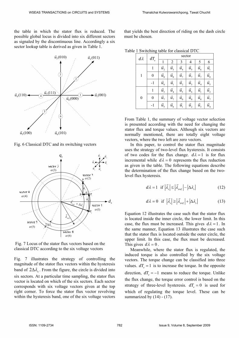
the table in which the stator flux is reduced. The possible global locus is divided into six different sectors as signaled by the discontinuous line. Accordingly a six sector lookup table is derived as given in Table 1.
1
23
4
65
2 (011)u
1(001)u
3(010)u
4 (110)u
5(100)u 6 (101)u
7 (111)u
0 (000)u
Fig. 6 Classical DTC and its switching vectors
sq
sd
(1)α
(2)α
(3)α
(4)α
srefλ
srefs
λλ+ Δ
2 sλΔ(5)α
(6)α
1u
3u
5u
4u
6u
2u
3P
2P 1
P
0P
3u
4u
3u
Fig. 7 Locus of the stator flux vectors based on the classical DTC according to the six voltage vectors Fig. 7 illustrates the strategy of controlling the magnitude of the stator flux vectors within the hysteresis band of 2 sλΔ . From the figure, the circle is divided into six sectors. At a particular time sampling, the stator flux vector is located on which of the six sectors. Each sector corresponds with six voltage vectors given at the top right corner. To force the stator flux vector revolving within the hysteresis band, one of the six voltage vectors
that yields the best direction of riding on the dash circle must be chosen. Table 1 Switching table for classical DTC
dλ edT sector
1 2 3 4 5 6
1
1 2u 3u 4u 5u 6u 1u
0 0u 0u 7u 7u 7u 0u
-1 6u 1u 2u 3u 4u 5u
0
1 3u 4u 5u 6u 1u 2u
0 7u 7u 0u 0u 0u 7u
-1 5u 6u 1u 2u 3u 4u
From Table 1, the summary of voltage vector selection is presented according with the need for changing the stator flux and torque values. Although six vectors are normally mentioned, there are totally eight voltage vectors, where the two left are zero vectors. In this paper, to control the stator flux magnitude uses the strategy of two-level flux hysteresis. It consists of two codes for the flux change. 1dλ = is for flux incremental while 0dλ = represents the flux reduction as given in the table. The following equations describe the determination of the flux change based on the two-level flux hysteresis.
1dλ = if s sref sλ λ λ≤ − Δ (12)
0dλ = if s sref sλ λ λ≥ + Δ (13)
Equation 12 illustrates the case such that the stator flux is located inside the inner circle, the lower limit. In this case, the flux must be increased. This gives 1dλ = . In the same manner, Equation 13 illustrates the case such that the stator flux is located outside the outer circle, the upper limit. In this case, the flux must be decreased. This gives 0dλ = . Meanwhile, where the stator flux is regulated, the induced torque is also controlled by the six voltage vectors. The torque change can be classified into three values. 1edT = is to increase the torque. In the opposite direction, 1edT = − means to reduce the torque. Unlike the flux change, the torque error control is based on the strategy of three-level hysteresis. 0edT = is used for which of regulating the torque level. These can be summarized by (14) - (17).
WSEAS TRANSACTIONS on CIRCUITS and SYSTEMS Thanatchai Kulworawanichpong, Tawat Chuchit
ISSN: 1109-2734 782 Issue 9, Volume 8, September 2009
Counter-clockwise direction:
1edT = if e eref eT T T≤ − Δ (14)
0edT = if e erefT T≥ (15)
Clockwise direction:
1edT = − if e eref eT T T≥ − Δ (16)
0edT = if e erefT T≤ (17) It should note that the selection of hysteresis band-width is the key. Too small band-width may cause loss of controllability.
3.2 DTC With Different Sophisticated Tables Improvement of direct torque control can be carried out in many different ways. The followings are some.
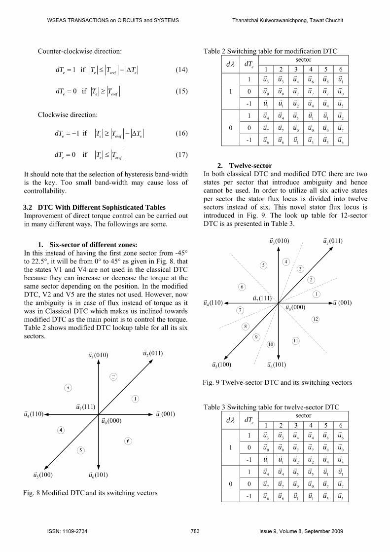
1. Six-sector of different zones: In this instead of having the first zone sector from -45° to 22.5°, it will be from 0° to 45° as given in Fig. 8. that the states V1 and V4 are not used in the classical DTC because they can increase or decrease the torque at the same sector depending on the position. In the modified DTC, V2 and V5 are the states not used. However, now the ambiguity is in case of flux instead of torque as it was in Classical DTC which makes us inclined towards modified DTC as the main point is to control the torque. Table 2 shows modified DTC lookup table for all its six sectors.
2 (011)u
1(001)u
3(010)u
4 (110)u
5(100)u 6 (101)u
7 (111)u
0 (000)u
Fig. 8 Modified DTC and its switching vectors
Table 2 Switching table for modification DTC
dλ edT sector
1 2 3 4 5 6
1
1 3u 3u 4u 6u 6u 1u
0 0u 0u 7u 7u 7u 0u
-1 1u 1u 2u 4u 4u 5u
0
1 4u 4u 5u 1u 1u 2u
0 7u 7u 0u 0u 0u 7u
-1 6u 6u 1u 3u 3u 4u
2. Twelve-sector In both classical DTC and modified DTC there are two states per sector that introduce ambiguity and hence cannot be used. In order to utilize all six active states per sector the stator flux locus is divided into twelve sectors instead of six. This novel stator flux locus is introduced in Fig. 9. The look up table for 12-sector DTC is as presented in Table 3.
1
2
34
6
5
2(011)u
1(001)u
3(010)u
4 (110)u
5(100)u 6 (101)u
7 (111)u
0 (000)u7
8
910
11
12
Fig. 9 Twelve-sector DTC and its switching vectors
Table 3 Switching table for twelve-sector DTC
dλ edT sector
1 2 3 4 5 6
1
1 3u 3u 4u 4u 6u 6u
0 0u 0u 7u 7u 0u 0u
-1 1u 1u 2u 2u 4u 4u
0
1 4u 4u 5u 5u 1u 1u
0 7u 7u 0u 0u 7u 7u
-1 6u 6u 1u 1u 3u 3u
WSEAS TRANSACTIONS on CIRCUITS and SYSTEMS Thanatchai Kulworawanichpong, Tawat Chuchit
ISSN: 1109-2734 783 Issue 9, Volume 8, September 2009
dλ edT sector
7 8 9 10 11 12
1
1 6u 6u 1u 1u 3u 3u
0 0u 0u 0u 0u 0u 0u
-1 4u 4u 5u 5u 1u 1u
0
1 1u 1u 2u 2u 4u 4u
0 7u 7u 7u 7u 7u 7u
-1 3u 3u 4u 4u 6u 6u
4 Simulation Results To verify the effectiveness of the proposed DTC, the stator flux was assumed to be regulated at 0.8 Wb while the electromagnetic torque was controlled accordingly as follows.
0.0 N.merefT = for 0 s t 0.5 s≤ ≤
0.5 N.merefT = for 0.5 s t 1.0 s≤ ≤
2.0 N.merefT = for 1.0 s t 1.5 s≤ ≤
1.0 N.merefT = for 1.5 s t 2.0 s≤ ≤
0.5 N.merefT = − for 2.0 s t 3.0 s≤ ≤ The test [13] was challenged by three different strategies of the switching table:
i) classical six-sector DTC of Table 1 ii) modified six-sector DTC of Table 2 iii) twelve-sector DTC of Table 3.
It notes that parameters of the test system can be obtained in [14]. The test was divided into three cases. Each case represented the change in sampling time or the hysteresis band-width. Also, each of which was performed the stator flux regulation and the torque control as given above by the three switching tables. All the three test cases were illustrated as follows.
4.1 Test 1:
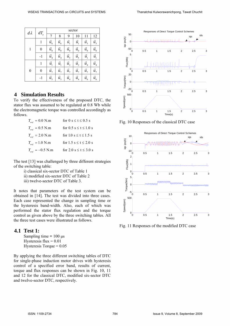
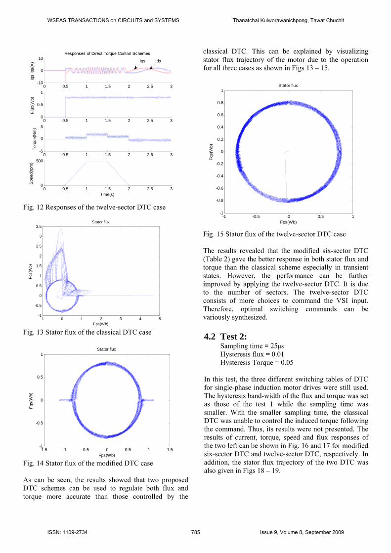
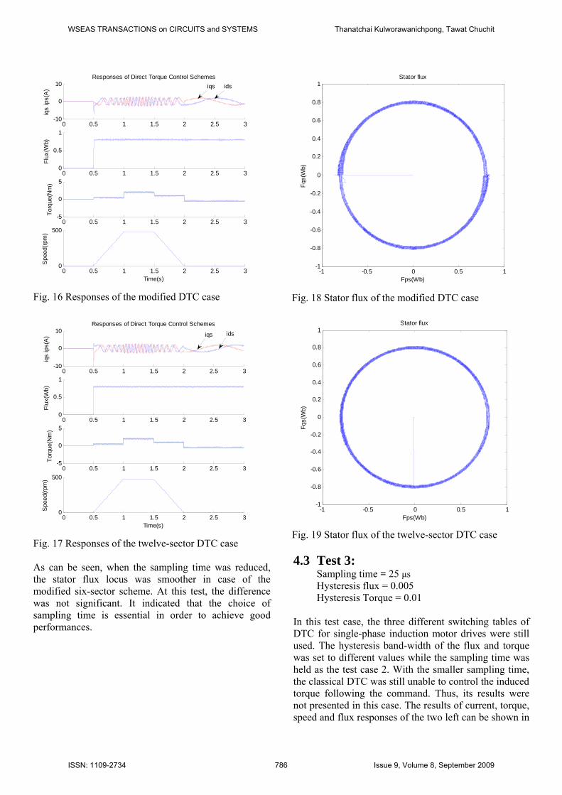
Sampling time = 100 μs Hysteresis flux = 0.01 Hysteresis Torque = 0.05
By applying the three different switching tables of DTC for single-phase induction motor drives with hysteresis control of a specified error band, results of current, torque and flux responses can be shown in Fig. 10, 11 and 12 for the classical DTC, modified six-sector DTC and twelve-sector DTC, respectively.
0 0.5 1 1.5 2 2.5 3-50
0
50
iqs
ips(
A)
Responses of Direct Torque Control Schemes
0 0.5 1 1.5 2 2.5 30
5
Flux
(Wb)
0 0.5 1 1.5 2 2.5 3-20
0
20
Torq
ue(N
m)
0 0.5 1 1.5 2 2.5 30
500
Time(s)
Spe
ed(rp
m)
iqs ids
Fig. 10 Responses of the classical DTC case
0 0.5 1 1.5 2 2.5 3-10
0
10
iqs
ips(
A)
Responses of Direct Torque Control Schemes
0 0.5 1 1.5 2 2.5 30
1
2
Flux
(Wb)
0 0.5 1 1.5 2 2.5 3-5
0
5
Torq
ue(N
m)
0 0.5 1 1.5 2 2.5 30
500
Time(s)
Spe
ed(rp
m)
iqs ids
Fig. 11 Responses of the modified DTC case
WSEAS TRANSACTIONS on CIRCUITS and SYSTEMS Thanatchai Kulworawanichpong, Tawat Chuchit
ISSN: 1109-2734 784 Issue 9, Volume 8, September 2009
0 0.5 1 1.5 2 2.5 3-10
0
10
iqs
ips(
A)
Responses of Direct Torque Control Schemes
0 0.5 1 1.5 2 2.5 30
0.5
1
Flux
(Wb)
0 0.5 1 1.5 2 2.5 3-5
0
5
Torq
ue(N
m)
0 0.5 1 1.5 2 2.5 30
500
Time(s)
Spe
ed(rp
m)
iqs ids
Fig. 12 Responses of the twelve-sector DTC case
-1 0 1 2 3 4 5-1
-0.5
0
0.5
1
1.5
2
2.5
3
3.5
Fps(Wb)
Fqs(
Wb)
Stator flux
Fig. 13 Stator flux of the classical DTC case
-1.5 -1 -0.5 0 0.5 1 1.5-1
-0.5
0
0.5
1
Fps(Wb)
Fqs(
Wb)
Stator flux
Fig. 14 Stator flux of the modified DTC case As can be seen, the results showed that two proposed DTC schemes can be used to regulate both flux and torque more accurate than those controlled by the
classical DTC. This can be explained by visualizing stator flux trajectory of the motor due to the operation for all three cases as shown in Figs 13 – 15.
-1 -0.5 0 0.5 1-1
-0.8
-0.6
-0.4
-0.2
0
0.2
0.4
0.6
0.8
1
Fps(Wb)
Fqs(
Wb)
Stator flux
Fig. 15 Stator flux of the twelve-sector DTC case The results revealed that the modified six-sector DTC (Table 2) gave the better response in both stator flux and torque than the classical scheme especially in transient states. However, the performance can be further improved by applying the twelve-sector DTC. It is due to the number of sectors. The twelve-sector DTC consists of more choices to command the VSI input. Therefore, optimal switching commands can be variously synthesized. 4.2 Test 2:
Sampling time = 25μs Hysteresis flux = 0.01 Hysteresis Torque = 0.05
In this test, the three different switching tables of DTC for single-phase induction motor drives were still used. The hysteresis band-width of the flux and torque was set as those of the test 1 while the sampling time was smaller. With the smaller sampling time, the classical DTC was unable to control the induced torque following the command. Thus, its results were not presented. The results of current, torque, speed and flux responses of the two left can be shown in Fig. 16 and 17 for modified six-sector DTC and twelve-sector DTC, respectively. In addition, the stator flux trajectory of the two DTC was also given in Figs 18 – 19.
WSEAS TRANSACTIONS on CIRCUITS and SYSTEMS Thanatchai Kulworawanichpong, Tawat Chuchit
ISSN: 1109-2734 785 Issue 9, Volume 8, September 2009
0 0.5 1 1.5 2 2.5 3-10
0
10
iqs
ips(
A)
Responses of Direct Torque Control Schemes
0 0.5 1 1.5 2 2.5 30
0.5
1
Flux
(Wb)
0 0.5 1 1.5 2 2.5 3-5
0
5
Torq
ue(N
m)
0 0.5 1 1.5 2 2.5 30
500
Time(s)
Spe
ed(rp
m)
iqs ids
Fig. 16 Responses of the modified DTC case
0 0.5 1 1.5 2 2.5 3-10
0
10
iqs
ips(
A)
Responses of Direct Torque Control Schemes
0 0.5 1 1.5 2 2.5 30
0.5
1
Flux
(Wb)
0 0.5 1 1.5 2 2.5 3-5
0
5
Torq
ue(N
m)
0 0.5 1 1.5 2 2.5 30
500
Time(s)
Spe
ed(rp
m)
iqs ids
Fig. 17 Responses of the twelve-sector DTC case As can be seen, when the sampling time was reduced, the stator flux locus was smoother in case of the modified six-sector scheme. At this test, the difference was not significant. It indicated that the choice of sampling time is essential in order to achieve good performances.
-1 -0.5 0 0.5 1-1
-0.8
-0.6
-0.4
-0.2
0
0.2
0.4
0.6
0.8
1
Fps(Wb)
Fqs(
Wb)
Stator flux
Fig. 18 Stator flux of the modified DTC case
-1 -0.5 0 0.5 1-1
-0.8
-0.6
-0.4
-0.2
0
0.2
0.4
0.6
0.8
1
Fps(Wb)
Fqs(
Wb)
Stator flux
Fig. 19 Stator flux of the twelve-sector DTC case
4.3 Test 3:
Sampling time = 25 μs Hysteresis flux = 0.005 Hysteresis Torque = 0.01
In this test case, the three different switching tables of DTC for single-phase induction motor drives were still used. The hysteresis band-width of the flux and torque was set to different values while the sampling time was held as the test case 2. With the smaller sampling time, the classical DTC was still unable to control the induced torque following the command. Thus, its results were not presented in this case. The results of current, torque, speed and flux responses of the two left can be shown in
WSEAS TRANSACTIONS on CIRCUITS and SYSTEMS Thanatchai Kulworawanichpong, Tawat Chuchit
ISSN: 1109-2734 786 Issue 9, Volume 8, September 2009
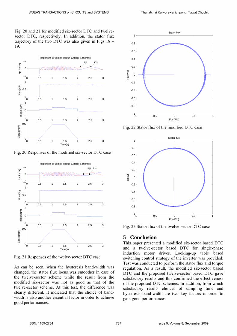
Fig. 20 and 21 for modified six-sector DTC and twelve-sector DTC, respectively. In addition, the stator flux trajectory of the two DTC was also given in Figs 18 – 19.
0 0.5 1 1.5 2 2.5 3-10
0
10
iqs
ips(
A)
Responses of Direct Torque Control Schemes
0 0.5 1 1.5 2 2.5 30
0.5
1
Flux
(Wb)
0 0.5 1 1.5 2 2.5 3-5
0
5
Torq
ue(N
m)
0 0.5 1 1.5 2 2.5 30
500
Time(s)
Spe
ed(rp
m)
iqs ids
Fig. 20 Responses of the modified six-sector DTC case
0 0.5 1 1.5 2 2.5 3-10
0
10
iqs
ips(
A)
Responses of Direct Torque Control Schemes
0 0.5 1 1.5 2 2.5 30
0.5
1
Flux
(Wb)
0 0.5 1 1.5 2 2.5 3-5
0
5
Torq
ue(N
m)
0 0.5 1 1.5 2 2.5 30
500
Time(s)
Spe
ed(rp
m)
iqs ids
Fig. 21 Responses of the twelve-sector DTC case As can be seen, when the hysteresis band-width was changed, the stator flux locus was smoother in case of the twelve-sector scheme while the result from the modified six-sector was not as good as that of the twelve-sector scheme. At this test, the difference was clearly different. It indicated that the choice of band-width is also another essential factor in order to achieve good performances.
-1 -0.5 0 0.5 1-1
-0.8
-0.6
-0.4
-0.2
0
0.2
0.4
0.6
0.8
1
Fps(Wb)
Fqs(
Wb)
Stator flux
Fig. 22 Stator flux of the modified DTC case
-1 -0.5 0 0.5 1-1
-0.8
-0.6
-0.4
-0.2
0
0.2
0.4
0.6
0.8
1
Fps(Wb)
Fqs(
Wb)
Stator flux
Fig. 23 Stator flux of the twelve-sector DTC case
5 Conclusion This paper presented a modified six-sector based DTC and a twelve-sector based DTC for single-phase induction motor drives. Looking-up table based switching control strategy of the inverter was provided. Test was conducted to perform the stator flux and torque regulation. As a result, the modified six-sector based DTC and the proposed twelve-sector based DTC gave satisfactory results and this confirmed the effectiveness of the proposed DTC schemes. In addition, from which satisfactory results choices of sampling time and hysteresis band-width are two key factors in order to gain good performances.
WSEAS TRANSACTIONS on CIRCUITS and SYSTEMS Thanatchai Kulworawanichpong, Tawat Chuchit
ISSN: 1109-2734 787 Issue 9, Volume 8, September 2009
6 Acknowledgment The authors would like to acknowledge the financial support of the research grant (MRG5080029) sponsored by the Thailand Research Fund, during a period of this work. References: [1] P.C. Krause, Analysis of Electric Machines,
McGraw-Hill, 1987. [2] N. Naewngerndee, C. Sukcharoen, T.
Kulworawanichpong, Simulation of Single-Phase Induction Motor Drives with Non-sinusoidal Power Supply. The WSEAS Transactions on Systems, Issue 5, Vol 5, pp. 1029-1034, 2006
[3] R. Krishnan, Electric motor drives – modelling, analysis and control, Prentice-Hall, 2001
[4] S. Raweekul, T. Kulworawanichpong, S. Sujitjorn, Parallel -Connected Single -Phase Induction Motor:Modelling and Simulation, The WSEAS Transactions on Circuits and Systems, Issue 3, Vol 5, pp. 377-384
[5] J.W.L. Nerys, A. Hughes & J. Corda, Alternative implementation of vector control for induction motor and its experimental evaluation, IEE Proceedings-Electric Power Applications, 147(1), 2000, pp. 7–13.
[6] M. Yano & M. Iwahori, Transition from slip-frequency control to vector control for induction motor drives of traction applications in Japan, The 5th International Conference on Power Electronics and Drive Systems, 2003, Saitama, Japan, pp. 1246–1251.
[7] S. Shinnaka, S. Takeuchi, A. Kitajima, F. Eguchi & H. Haruki, Frequency-hybrid vector control for sensorless induction motor and its application to electric vehicle drive, IEEE 16th Annual Applied Power Electronics Conference and Exposition, 2001, Yokohama, Japan, pp. 32–39.
[8] M. Benhaddadi, K. Yazid & P. Khaldi, An effective identification of rotor resistance for induction motor vector control, Proc. IEEE Instru. and Meas. Tech. Conf., 1997, Ottawa, Canada, pp. 339–342.
[9] P. Vas, Sensorless Vector and Direct Torque Control, Oxford University Press,1998.
[10] Y.V.Siva Reddy, M.Vijayakumar and T. Brahmananda Reddy, Direct Torque Control of Induction Motor Using Sophisticated Lookup Tables Based on Neural Networks, AIML Journal, June 2007.
[11] F.A.S. Neves, E.B.S. Filho, J.M.S. Cruz, R.P. Landim, Z.D. Lins, A.G.H. Accioly, Single-phase induction motor drives with direct torque control, The 28th Annual Conference on IEEE Industrial Electronics Society (IECON02), 2002.
[12] R. de F. Campos, L.F.R. Pinto, J.de Oliveira, A.Nied, L.C.de Marques, A.H.de Souza, Single-Phase Induction Motor Control Based on DTC Strategies, IEEE International Symposium on Industrial Electronics (ISIE 2007), 4-7 June 2007.
[13] T. Kulworawanichpong and T. Chuchit, Improved direct torque control for single-phase induction motor drives, The 9th WSEAS International Conference on Power Systems, 3 – 5 September 2009, Budapest, Hungary, pp. 152 – 157.
[14] N. Naewngerndee and T. Kulworawanichpong, Voltage-dependent parameter refinement for single-phase induction motors using genetic algorithms, The WSEAS Transaction on System and Control, Vol. 4, Issue 1, pp. 45 – 54, 2009
WSEAS TRANSACTIONS on CIRCUITS and SYSTEMS Thanatchai Kulworawanichpong, Tawat Chuchit
ISSN: 1109-2734 788 Issue 9, Volume 8, September 2009