modes of traveling wave particle transport and their applications
TRANSCRIPT
ELSEVIER Journal of Electrostatics 34 (1995) 225-244
Journal of
ELECTROSTATICS
Modes of traveling wave particle transport and their applications
Fred W. Schmidlin*
Xerox Webster Research Center, 800 Phillips Road, Webster, NY 14580, USA
Received 12 April 1993; accepted after revision 27 October 1993
Abstract
Building on prior work by Masuda and by Melcher, Warren, and Kotwal (MWK), the idealized problem of a particle driven by either a pure sinusoidal boundary wave alone or mixed with a counter moving harmonic is studied. The pure wave case is revisited to (a) support a conjecture that particles must stop (or stick) motionless whenever in contact with a transport grid to obtain MWK's "hopping mode" (HM), while freedom to slip under otherwise identical conditions results in the author's "surfing mode" (SM), and (b) establish a reference base for evaluating the effects of a harmonic wave. The latter is shown to extend the normal "curtain mode" (CM) of Masuda to higher frequencies, with the particle drifting in the same direction as the fundamental wave. This is the contradiction to the prediction of perturbation theory that the particle starts drifting backwards (opposite to the fundamental wave direction) at suffi- ciently high frequencies. At high frequencies the loss of levitation and collisions with the grid surface preclude the onset of backwards transport in the presence of normal strength (weaker than the fundamental) harmonics. Backwards transport does appear in numerical experiments at high frequencies, even for a pure wave, but is found to be an artifact of time increments of integration that are too large. Backwards transport driven by a harmonic that is stronger than the fundamental, as ingeniously constructed by Masuda to separate different particle species, is confirmed in accurate numerical experiments. A normal (Fourier component) harmonic is not an important scattering source for particles in the SM. Auxiliary considerations pertinent to the various applications of traveling wave particle transport are discussed.
1. Introduction
The m o v e m e n t of par t i cu la te ma t t e r wi th e lec t ros ta t ic runn ing waves is an interest- ing p h e n o m e n o n tha t p roduces m a n y different modes of par t ic le m o t i o n which are po ten t i a l ly useful in a wide var ie ty of app l i ca t ions I-1-12]. The idea of s imul taneous lev i ta t ion and t r a n s p o r t of ma t t e r wi th t ravel ing waves was first conceived by M a s u d a
* Retired, current address: 8 Forestwood Lane, Pittsford, NY 14534, USA.
0304-3886/95/$09.50 © 1995 Elsevier Science B.V. All rights reserved. S S D I 0 3 0 4 - 3 8 8 6 ( 9 4 ) 0 0 0 3 5 - 2
226 F. W. Schmidlin/Journal of Electrostatics 34 (1995) 225-244
[1-3]. He called this phenomenon the electric curtain (EC) effect. He produced traveling waves inside tubes [1] by wrapping three electrodes (parallel wires) in a spiral around the outside of the tube and connected the electrodes in proper sequence to the output of a 3-phase generator. He subsequently invented a flat panel version of EC [2] by arranging an array of linear electrodes in a grid-like structure and connecting every third (nth) electrode to a 3-phase (nth-phase) generator. These fiat panels produce planar boundary waves that clean and transport unused power from the walls of a (dry) paint spray booth [3]. The particles are lifted out of contact with the grid and pushed in the direction of the wave while orbiting in a cycloid. This type of particle motion is characteristic of transport with the EC and is referred to as the curtain mode (CM).
Unaware of Masuda's work, the author independently conceived of using an electrostatic traveling wave to push xerographic toner (charged pigment particles) in sliding contact along a planar surface [7, 8]. The idea is to push toner along a surface with the tangential electric field while holding it in contact with that surface with the normal field. The process is the analog of the way surfers ride water waves. This mode of transport is therefore referred to as the "surfing" mode (SM). The structure conceived to generate electrostatic traveling waves to drive the SM mode of transport is called a charged toner conveyor (CTC). It is similar in form to the planar type of EC, but as explained more fully later on, the CTC is designed to produce waves shorter in length to provide more operating latitude free of air breakdown. The key features which distinguish the transport modes desired with the EC and CTC are, respectively, (a) the CM-particles move slower than the wave while being continuously repelled away from the grid surface; and (b) the SM-particles move the same speed as the wave while being continuously drawn towards the grid surface.
Another mode of transport with characteristics similar to the SM, yet clearly distinguishable from it, at least theoretically, is known as the "hopping mode" (HM). The name was coined by Jim Melcher and coworkers [11] to describe the kind of particle motion which they identified on the EC at low temporal frequencies. An in-depth study by Melcher et al. (MWK) [11, 12] clearly elucidates the physical basis of the CM and provides numerical HM trajectories consistent with their experimental results. Curiously however, their analysis in I-11, Section 5] on particle motions in two dimensions does not reveal the existence of the SM, while it does appear among the solutions for the one-dimensional case.
The absence of any SM solutions in two dimensions by MWK and a claim by the late Professor Melcher (private communication) that it may not exist stimulated further theoretical investigations. The results of this study are reported here along with a number of other new discoveries which specialists in the field of traveling wave transport may find helpful.
The conditions which result in a HM vs. a SM now appear quite clear theoretically, but the distinction between which mode actually exists in a given experiment can be very subtle. In fact, early experiments with the CTC [8] revealed the particles moving as "tiny clouds" at the wave speed. This is explained by scattering due to roughness of the grid surface. The scattering event nudges the particle away from its equilibrium position on the wave, introducing a transient perturbation which damps away as the

F.W. Schmidlin/Journal of Electrostatics 34 (1995) 225-244 227
particle relaxes back towards its stable equilibrium position on the wave. Physical evidence to support this view is discussed in [8], but the similarity between such a perturbed SM and the HM can make it difficult to discern which mode is active or predominant. The difference is a matter of degree in displacement distance away from the grid surface and how it relates to the underlying drive mechanism. Scattering is dependent on the degree of surface roughness, and changes in surface roughness have produced the expected effect [8]. Hop height, on the other hand, is dependent on the magnitude of the adhesive force between the toner and grid surface, but no experi- mental investigation of this has been made, to my knowledge.
There is little doubt that particle sticking to the grid surface precludes the SM and may force the HM. If the normal field is strong enough to break the adhesive bond the particle will lift off the grid where it can be propelled ahead of the wave and into a downward field region which brings the particle back into contact with the grid. If the particle sticks again instead of recoiling from the surface, it will remain motionless on the grid until the wave catches up and initiates the process over again. Such is the nature of the HM. Since excursions from the grid surface also occur for the perturbed SM, the two modes may appear very similar. To distinguish between them experi- mentally, additional experiments may prove to be essential.
Practical grid structures are comprised of periodic arrays of metallic conductors separated by dielectric. Voltages applied to these conductors produce an electric field in the adjoining medium which is complex and best represented as a Fourier series [11, 8, 6]. Inventions and insights concerning the nature of traveling wave transport, however, have been gleaned through the study of particle motions driven by the simple sinusoidal boundary wave shown in Fig. 1. This corresponds to the first term of a Fourier expansion of a boundary wave for a practical structure. It is reexamined herein once again to establish a firmer foundation for understanding the basis for the different modes of transport. Then, following Masuda [6, 9], the forcing function is
V
O
/
\
I
- - 5 - - 3
I
- - 3 -
/ /
/
/
/
I I I
3 5
Fig. 1. Potential well for particle moving with an idealized pure sinusoidal wave.
228 F.W. Schmidlin/Journal o f Electrostatics 34 H995) 225-244
a
,; %
-'\
:" ,,,
/ ", f* . : 4 ,~ I >,, A
/ ~/ /' %/
/
/
j ' " \
.,,' ,
"1 ?'~ ¢. \ , j L ,
\ . /
i i i J i
--3 --i ~ 1 U
[ [ [ i 1
- - 5 3 5
V
O \
I i I L L i L i i i i
--5 ~3 --i 0 1 3 5
....... AO=O , ~/2 o x
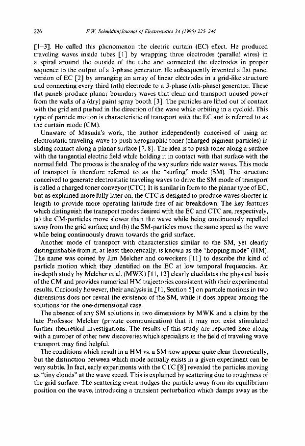
Fig. 2. The fundamental and second harmonic waves for three-phase grid illustrated (a) individually and (b) superposed at selected times to indicate time-dependent changes in potential well seen by particle moving with the fundamental wave.
extended to include the next finite term in the Fourier expansion of the boundary wave for selected practical transport grids. This is especially interesting because the largest non-vanishing harmonic propagates in the direction opposite to that of the fundamental wave, and particle drift in this direction is predicted by perturbation theory [6]. The fundamental and second harmonic (n -- 2) for a 3-phase grid is shown in Fig. 2(a). The constantly changing resultant wave, as seen by a particle attempting to follow the fundamental wave, is illustrated for selected times in Fig. 2(b). Surpris- ingly, particle motions that result from this complex driving function differ little from those driven by the fundamental alone. This is shown in detail later. Another surprising result for this countermoving wave case is the absence of any backwards trajectories among the numerical solutions. This is contrary to the predictions of
F.W. Schmidlin/Journal of Electrostatics 34 (1995) 225-244 229
perturbation theory [6]. However, if the amplitude of the second harmonic is en- hanced to match conditions cleverly constructed by Masuda [9] for the purpose of separating different particle species, backwards transport is found among the numer- ical solutions. This is consistent with the experimental observations reported by Masuda, though consistency with the perturbation solution now appears to be fortuitous.
The generic problem defined by the fundamental wave and one countermoving harmonic turns out to be broadly applicable to a wide variety of multiphase grid structures. In general, the largest Fourier component, next to the fundamental, is just one less than the number of driving phases, and it always propagates in the direction opposite to the fundamental. Specifically, for the 4-phase grid, the largest harmonic is n = 3; the second vanished due to symmetry. This case is special because the countermoving wave may act as a scattering source for particles moving in the SM on the CTC. Later results show, however, that this scattering effect is negligible.
Another previously unsolved puzzle is the appearance of backwards moving trajectories among numerical solutions even for the case of a pure wave driving function. However, it is now identified as a numerical artifact that arises from using excessively large time increments of integration in conjunction with high frequencies.
In the sections to follow, all of the effects alluded to above are developed in some detail. Through out we adopt the notation of M W K (see Notation section, where all pertinent quantities are listed). Following the equations of motion, the steady-state solutions for the "pure" (idealized sinusoidal) wave are reviewed and extended. Their connection with the three possible transport modes are established. A numerical solution for a special case treated by M W K is shown to be identical to theirs. But at a slightly reduced frequency, an SM trajectory is obtained rather than the HM, as expected according to them. Other special solutions are examined to illustrate the effect of toner mass on particle trajectories. These also serve as a reference for showing that the effect of a normal strength harmonic wave is surprisingly small. Insights gained from these new results pertinent to the interpretation of several experiments are discussed. Finally, the main conclusions from this study are sum- marized.
2. Equations of motion
Building on prior work [6, 8, 11], the dynamics of a particle is expressed in terms of its phase position 0 relative to the fundamental wave:
d20 d0 M~-~ + ~ + Q = - e -z sin(0) - A.e -"~ sin(n0 + (n + 1)~2t) - #F*, (1)
d2z dz M-cT~at_ + -d-[ = Fz, (2)
230 F.W. Schmidlin/Journal of Electrostatics 34 (1995) 225-244
where
Fz = - e-~ cos(0) - A,e-"Z cos(n0 + (n + 1)12t) - G - I/(1 + z/ak) 2, (3)
F. z=~Fz i f F z < 0 and z = 0 , (4a) otherwise. (4b)
The constant A, quantifies the strength of the countermoving harmonic. Setting A, = 0 recovers the pure wave case studied previously. For the definitions of other terms, see the notation section.
3. Pure wave analysis
The basis for the three different transport modes lies among the steady-state solutions of Eqs. (1)-(4) for the pure wave case (A. = 0). Solutions for this case are examined first to address the disagreement with M W K and establish a reference base for when the harmonic is later switched on, A. > 0.
3.1 Conditions for the three modes
The SM [8] follows from the simplest time-independent solution of Eqs. (1)-(4). Interpreting /~ in Eq. (1) as a coefficient of sliding friction, the steady-state time- independent solution becomes: z = 0, and the equilibrium phase position for the particle riding the wave is
0e = a rcs in{-cos (B) [ f2 + / t ( G + I)]} - B, B = arctan/~. (5)
In the frictionless limits (p = 0), this reduces to
0 e = arcsin (-- f2). (6)
As shown previously [8], 0e must fall in the first quarter wave immediately following the potential minimum in Fig. 1, i.e., - rt/2 < 0e < 0, for the SM to be stable. For frictionless sliding (# = 0), this means 12 < 1. Physically, the particle must slide back on the wave (up the potential well) far enough for the tangential force (slope of the potential well) to balance the viscous drag. With friction against the grid, the particle must shift farther back on the wave. It can be shown that the amount of this shift decreases with increasing frequency and the residual shift as f2 approaches unity clips the upper limit of f2 to less than unity. For example, for the parameters considered by MWK (G = 0.0089, I = 0.0819), the maximum (2 for a stable SM reduces from 1 to 0.91 as/~ increases from 0 to 1.
Interestingly, the above stability requirement (meaningful for the SM only) is largely redundant to MWKs requirement for synchronous transport (particle speed equal to the wave speed) in general. Because of viscosity, the wave velocity (~/k) must be less than the maximum velocity attainable for a particle pushed with a field of Eo
F. 14I. Schmidlin/Journal of Electrostatics 34 (1995) 225-244 231
(in still air), namely bEo. Thus f2 = (09/k)/bEo < 1, called the drift limitation, is necessary for both the SM and HM.
Another physical requirement for the SM, in particular, is sufficient acceleration force for a particle to catch the wave. As shown by numerical analysis [8], a particle (for M = 14) starting from rest can catch the wave only if 09 < 1.7o90. In the present notation this acceleration limitation translates into t2 < 1.7/x/-M. The explicit mass dependence exhibited here shows that this criterion is more restrictive than the drift limitation for M > 3. For toner used in the CTC experiments, M is typically > 10, whence Q > 0.5. Thus, the acceleration limitation is in effect and the drift limitation becomes irrelevant. This should be contrasted with the experiments by MWK for which M ~ 1. Here the drift limitation comes into effect and the acceleration limit is irrelevant. Further significance to the difference in M in the two studies is discussed in Section 5.
In general, the final steady-state mode achieved by a particle is very sensitive to initial conditions for all 12 < 1. For example, a window in phase angle vs. frequency space exists [8] that enables particles to catch a wave (achieve the SM) starting from rest. Everywhere outside this window, which includes some phase angles even at zero frequency, the CM is obtained. The full dependence of this window on M is not yet established, but a few selected numerical experiments indicate that it does not change dramatically for low M as well. In attempts to reproduce the solutions reported by M W K it was found that their HM solutions could be accurately recovered only if the initial phase angle is chosen to coincide with the point in time where the net normal force on a particle (QE~- Fz) turns positive, i.e., when 0o = - arccos(G + I). This initial phase angle is appropriate when particles stick to the surface of a grid and move only after being lifted off by the normal force. It may be the appropriate choice in their case in order to obtain solutions in agreement with their experimental studies. They worked with relatively weakly charged toner which they loaded onto the transport grid with a hand brush. Such toner may be suffi- ciently sticky to resist slipping along the grid. This situation contrasts with the CTC experiments where well-charged toner was deposited onto the conveyor with a mov- ing magnetic brush. MWK's claim to get the HM with slipping as well, however, is a puzzle. A relevant though insufficient explanation may be that even in that case they did not consider arbitrary initial phase angles. M W K did show [1 l, Fig. 8] that different final modes of motion are achieved for 0.5 < f2 < 1, depending on whether the particles are started from the grid surface or "dropped from above". Further clarification calls for a more exhaustive study of all possible initial conditions for particles of different M. But, in lieu of this, a reasonable conjecture at this point is that the primary determinant of whether the HM or SM is achieved is simply sticking vs. slipping.
Steady-state solutions to Eqs. (1)-(4) for t2 > 1 must possess an oscillatory charac- ter like the CM. This follows from the fact that the particle must respond to the undulations of the faster moving wave passing it by. M W K [1 1] have shown that their numerical solutions agree well with the analytic perturbation solutions for t2 >> 1, and explain why the perturbation solutions break down for f2 near 1. Selected numerical solutions for the high-frequency range are examined in Section 3.3.
232 F. V£ Schmidlin/Journal o f Electrostatics 34 (1995) 225-244
1 . o
Z
o . s
a
t~ = .88 eo = - 1.662
o - ~ I o
r: ',
: I i I
' • r r,
\ /
i J i
.~I 4.
0.15
0.1
Z
0.05
)
, . \
' b
' ~ = .84 ~ Oo =-1 .662
I
I
I J
. . . . i . . . . . . . . . . . . . L
- 2 0 2 4 6 a 1 0 z 2 za . z 6 a .s
X
0 .09
0 . 0 8
0 . 0 " 7
0 . 0 6
0 . 0 5
Z 0 . 0 4
0 ° 0 3
0 . 0 : 1
0 . 0 1
0
c
£~ : . 88
Oo = - 1 . 6 2
4 • e lo :1.2 x4 14; ~.IS
X
d
t~ = . 8 8
Oo = - ! . 5 8
- 2 2 • ~ • ~ o 1 2 ~ 4 X 6 x e
X
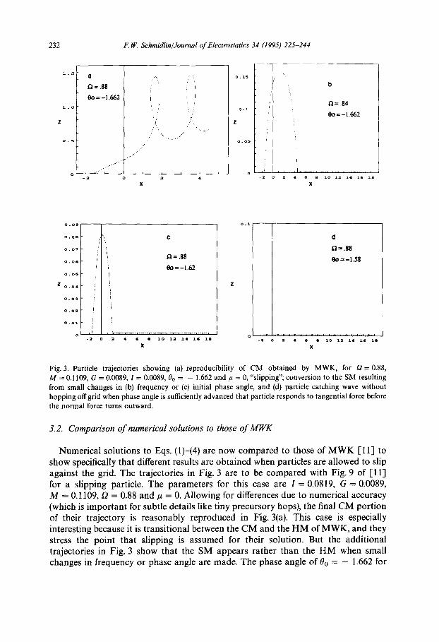
Fig. 3. Particle trajectories showing (a) reproducibility of CM obtained by MWK, for ~2 = 0.88,
M = 0.1109, G = 0 .0089, I = 0 .0089, 00 = - 1.662 a n d kt = 0, "slipping"; conversion to the SM resulting from small changes in (b) frequency or (c) initial phase angle, and (d) particle catching wave without hopping off grid when phase angle is sufficiently advanced that particle responds to tangential force before the normal force turns outward.
3.2. Comparison of numerical solutions to those of MWK
Numerical solutions to Eqs. (1)-(4) are now compared to those of M W K [I 1] to show specifically that different results are obtained when particles are allowed to slip against the grid. The trajectories in Fig. 3 are to be compared with Fig. 9 of [11] for a slipping particle. The parameters for this case are I = 0.0819, G = 0.0089, M = 0.1109, [2 = 0.88 and/~ = 0. Allowing for differences due to numerical accuracy (which is important for subtle details like tiny precursory hops), the final CM portion o f their trajectory is reasonably reproduced in Fig. 3(a). This case is especially interesting because it is transitional between the CM and the HM of MWK, and they stress the point that slipping is assumed for their solution. But the additional trajectories in Fig. 3 show that the SM appears rather than the HM when small changes in frequency or phase angle are made. The phase angle of 0o = - 1.662 for
F.W. Schmidlin/Journal of Electrostatics 34 (1995) 225-244 233
Fig. 3(a) is - arccos(G + I), corresponding to the point where the net normal force turns positive. A small reduction in frequency, Fig. 3(b), or a slightly more advanced initial phase angle, Fig. 3(c), ends in the SM after one initial hop. A further advance- ment in phase angle, Fig. 3(d), enables the particle to slip into the SM without leaving the grid surface. This illustrates the persistent nature of the SM when the particle is free to slip. In no case was the HM obtained without sticking.
It should be emphasized that solutions at the very edge of the SM window, like the one above or at high frequencies, are sensitive to numerical accuracy. Most results reported herein were obtained using the simple Euler method [14] programmed on a Lotus spreadsheet. Several thousand time steps, less than or equal to the wave period divided by 200, proved to be required to identify the steady-state character of a solution with reasonable accuracy. Accuracy was tested by halving the time steps, or making comparisons with solutions using the fourth-order Runge-Kutta technique [14]. The latter proved to be inconvenient with spreadsheet analysis because memory limited the time range. The problem admittedly invites revisitation with more sophis- ticated numerical tools.
3.3. Curtain modes for high t2 and M
While solutions for f2 > 1 always exhibit a CM character, boundary scattering precludes the achievement of a persistent steady-state trajectory when f2 reaches a threshold value, depending on M and G. It is instructive to examine examples of this phenomenon for the pure wave cast first so the effect of a harmonic wave included later can be appreciated. Interesting transient and numerical accuracy effects also appear here with a pure wave driving function at high f2 and M.
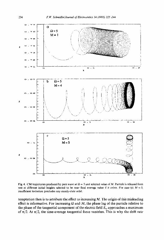
Solutions for f2 = 5, G --- 0.0089 and different M are shown in Fig. 4. Note that for M = 1 (Fig. 4(a)) the average height above the grid is about 0.74 (normalized units) and the cycles appear to reach a uniform spacing relatively soon. At M = 4 (Fig. 4(b)) the average height drops more than an order of magnitude and the cycle diameter decreases at a much smaller rate. The tightness of the cycloid near the end indicates that the drift rate has nearly vanished. At M = 5 (Fig. 4(c)) the particle can no longer be levitated, whence it falls into the grid and becomes scattered into a new trajectory. For this series of solutions the initial release height was chosen in the neighborhood of the final steady-state height. Higher initial heights simply extend the transient region while the particle falls toward the steady-state height where the levitation force balances the gravitational force. The graphs appear more legible when such extended transient regions are avoided.
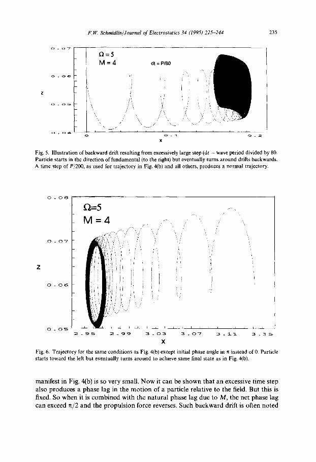
Fig. 5 now illustrates the artifact that arises when the time step is too large. Near the end of the trajectory (on the right), the particle reverses its drift direction. This should be compared to Fig. 4(b) where all conditions except the numerical time step are identical. For Fig. 5 the time step is P/80 where P is the wave period. For Fig. 4 and all other cases the time step is P/200. It should be pointed out that this particular artifact appears only in conjection with large g2 and M. Thus, if one unknowingly explores the dependence of numerical solutions on M while using an unfortunately chosen step size, the reverse drift motion will appear at some threshold in M. The natural
234 F, ~ Schmidlin/Journal of Electrostatics 34 (1995) 225-244
:~ ~ ~,' ' ' :' ,<, ;',' : ' i ' " ? ' ' ~ ' V " ' ~ , , .,, t,'; '< +<'>Y <. , ' v , ' . , ' : ~ , ' , ' , ' , , "
I ~ ~ : ! ::I : ;i!J ;~:IA ~ ; . . . . I / , ! , , ! ,~: li)~ : , '< , \ , t , ; ~ , f , ; ; < i l f.~ 7 7 ~ ' t f { ' ~ ! i
', ' ' ' " \ ' < , I ' 7 .+ Ik~ i " 7 ~z T M i ,
', ? , ,,
X
?_ i t> t-l---5 i , M=4
I
- ' !i/ - [ ; , \ ,
, \ "\ //'
0
,' !,! iti
<, . . . . . x , ,,, ;, I ) t ~ k i l
X
L-
0
< Q f l=5 M=5 ) .....
7 ,;i;;:J
~ _ ; I . . 0 . ;~i !
X
Fig. 4. CM trajectories produced by pure wave at D = 5 and selected value of M. Particle is released from rest at different initial heights selected to be near final average value if it exists. For case (c) M = 5, insufficient levitation precludes any steady-state orbit.
temptation then is to attribute the effect to increasing M. The origin of this misleading effect is informative. For increasing 12 and M, the phase lag of the particle relative to the phase of the tangential component of the electric field E~ approaches a maximum of st/2. At hi2, the time-average tangential force vanishes. This is why the drift rate
F.W. Schmidlin/Journal of Electrostatics 34 (1995) 225-244 235
f~=5 M=4
x \
i , I
o
dt = P/80
/
!i / i
/ ' \ , ~ \
/ \ ...... / \,. ..... -.,- - - -...
o ~_
X
L
O 2
Fig. 5. Illustration of backward drift resulting from excessively large step (dr = wave period divided by 80. Particle starts in the direction of fundamental (to the right) but eventually turns around drifts backwards. A time step of P/200, as used for trajectory in Fig. 4(b) and all others, produces a normal trajectory.
Z
O. 0 8
0 . 0 7
O. 0 6
0 . 0 5
~(~'--5 -
M=4
II
i'! i/
2 . 9 5
i
i
I i i
2 . 9 9
I ~ I L 1 L I I I 1 I ~ L i
3 . 0 3 3 . 0 7 3 . i i 3 . 1 5
x
Fig. 6. Trajectory for the same conditions as Fig. 4(b) except initial phase angle in n instead of 0. Particle starts toward the left but eventually turns around to achieve same final state as in Fig. 4(b).
manifest in Fig. 4(b) is so very small. Now it can be shown that an excessive time step also produces a phase lag in the motion of a particle relative to the field. But this is fixed. So when it is combined with the natural phase lag due to M, the net phase lag can exceed ~/2 and the propulsion force reverses. Such backward drift is often noted

2 3 6 F.W. Schmidlin/Journal of Electrostatics 34 (1995) 225-244
in the literature, without explanation. In light of these results, the occurrence of backwards trajectories in numerical experiments should be treated with caution.
The above point does not rule out a reversal in the drift direction of a particle in general however. In fact, this happens when initial conditions are selected that send the particle off in the wrong direction at the beginning, as illustrated in Fig. 6. The orbit shown here starts moving from right to left, against the wave direction, and eventually turns around to drift from left to right. This orbit should be compared with that in Fig. 4(b) where all conditions are the same except the initial phase angle is 0 instead of it.
Figs. 5 and 6 also illustrate the extended transient that accompanies larger t2 and M. In dimensionless units, the relaxation time is MO cycle. This can result in a wide range of complex solutions simply by changing the initial conditions. For example, the initial drift direction of the particle can be rotated full circle by increasing 00 from 0 to 2n. For most of the trajectories illustrated herein, the initial conditions are chosen to approximate the final state, making it easier to establish the character of the eventual steady state.
4. Particle motions driven by fundamental and harmonic waves combined
Changes to the foregoing particle trajectories when a countermoving harmonic is added to the pure wave are now examined. Driving functions suitable for the 3-phase and 4-phase grids are chosen. For the 3-phase grid n = 2 and A2 = V2/VI = 0.42, as illustrated in Fig. 2(b). For the 4-phase grid, n = 3 and A 3 --- V3/V 1 = 0.27. It should be stated that for both of these cases the wave amplitudes are approximations derived from Fourier transforms of voltage waves at the grid surface that are assumed to vary linearly between the electrodes. A rigorous analysis would require solutions of LaPlace's equation with the proper boundary conditions applied along the boundary between the electrodes.
4.1. Approximate perturbation result
To facilitate a search for backward modes among the numerical solutions of Eqs. (1)-(4), the perturbation solution of Masuda [6] was reconstructed in terms of the M W K notation I-11]. Leaving out many details, the time-average levitation force and time-average drift speed u lead to the following expressions:
G 1 [e -2z nA~ 1 + M 2 ( a - u ) 2 -2,,z-] = 1 + M 2 ( a - u) 21 + 1 + M 2 ( a + nu) 2e J' (7)
U - - 1 Ee z u,2 1 (f2 -- u)(1 + M2(t2 - u) 2) \(f2 + nu)] 1 + M2(O + nu) 2 e-z"z I
(8)
F.W. Schmidlin/Journal of Electrostatics 34 (1995) 225-244 237
I .5
z
io3 u 3.
O. 5
0
--(D.~
a
i 3 f~
5
l o o o u ( n = 2 ) o z ( n = 3 )
I
I I
I
I I
7
i o o o u ( n = 3 >
I
z 103u
0 . 5
b i [
- - O . 5 I 1 3 5 7
[ ~ ( n i 2 ) ~ O 0 0 U ( nl 2 ) ¢ ~ ( n : ~ ) l O 0 0 u ( n : 3 )
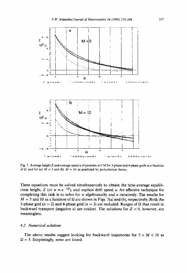
Fig. 7. Average height Z and average speed u of particles in CM for 3-phase and 4-phase grids as a function of (2, and for (a) M = 5 and (b) M = 10, as predicted by perturbation theory.
These equations must be solved simultaneously to obtain the time-average equilib- rium height, Z (or w = e-2Z), and explicit drift speed u. An effective technique for completing this task is to solve for w algebraically and u iteratively. The results for M = 5 and 10 as a function of f2 are shown in Figs. 7(a) and (b), respectively. Both the 3-phase grid (n = 2) and 4-phase grid (n = 3) are included. Ranges of t2 that result in backward transport (negative u) are evident. The solutions for Z < 0, however, are meaningless.
4.2. Numerical solutions
The above results suggest looking for backward trajectories for 5 < M < 10 at I2 = 5. Surprisingly, none are found.
238 F. 1t<. Schmidlin/Journal o f Electrostatics 34 (1995) 225-244
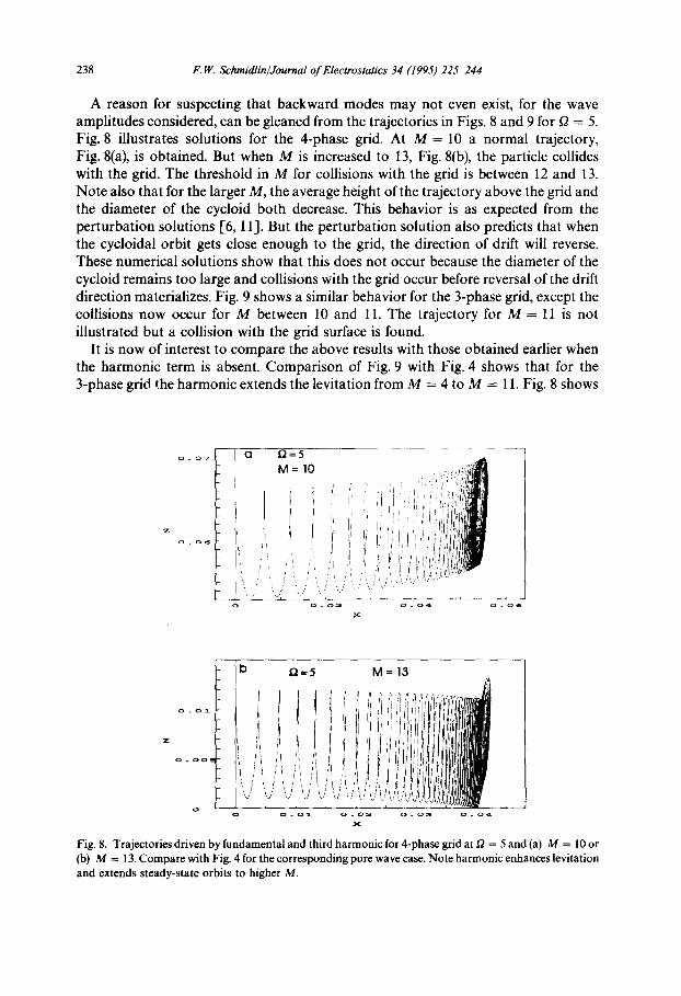
A reason for suspecting that backward modes may not even exist, for the wave amplitudes considered, can be gleaned from the trajectories in Figs. 8 and 9 for £2 = 5. Fig. 8 illustrates solutions for the 4-phase grid. At M = 10 a normal trajectory, Fig. 8(a), is obtained. But when M is increased to 13, Fig. 8(b), the particle collides with the grid. The threshold in M for collisions with the grid is between 12 and 13. Note also that for the larger M, the average height of the trajectory above the grid and the diameter of the cycloid both decrease. This behavior is as expected from the perturbation solutions [6, 11]. But the perturbation solution also predicts that when the cycloidal orbit gets close enough to the grid, the direction of drift will reverse. These numerical solutions show that this does not occur because the diameter of the cycloid remains too large and collisions with the grid occur before reversal of the drift direction materializes. Fig. 9 shows a similar behavior for the 3-phase grid, except the collisions now occur for M between 10 and 11. The trajectory for M = 11 is not illustrated but a collision with the grid surface is found.
It is now of interest to compare the above results with those obtained earlier when the harmonic term is absent. Comparison of Fig. 9 with Fig. 4 shows that for the 3-phase grid the harmonic extends the levitation from M = 4 to M = 11. Fig. 8 shows
D = 5 M = I O
; ' , !i i! ~ i , ' i
0 . 0 2 0 .04
',il 'l!I,~fi|
'i :/i
i
0 . 0 6
b D = 5
o o . o i
M = 1 3
...... i~ !
03 0. 04
Fig. 8. Trajectories driven by fundamental and third harmonic for 4-phase grid at ~ = 5 and (a) M = 10 or (b) M = 13. Compare with Fig. 4 for the corresponding pure wave case. Note harmonic enhances levitation and extends steady-state orbits to higher M.
F.W. Schmidlin/Journal of Electrostatics 34 (1995) 225-244 239
o D.=5
M = 5
",i
¢D . 2 , 0 ~ 0 0 _ 0 2
. . . . . . b ~=5 M = I O 0 _ 0 3 7 i- o:o~: : . . . . . . . . , . ~
. . . . . . . i i ; ii i ill
. . . . . - ~ i i I L i l ~ t / l l iB . . . . i- ! I t I i i I ! i i d l i ~
= ° ° : ° ~ : : ', i i i / ( i i!/llllBB . . . . . - ~ i i i i i ) I ! ; ) ~
. . . . . l- : , , ~ t I , ~ | ] l m
rJJ J ~' {~' 'ii ~ ! ii~ ! ' i/'ii ~]l ~[!wLIBI~ . . . . . ! : / k I !: ~ . . . . , ~! t I l "~
o o.o~_ 0 . 0 2 o . o 3 0 . 0 4
x
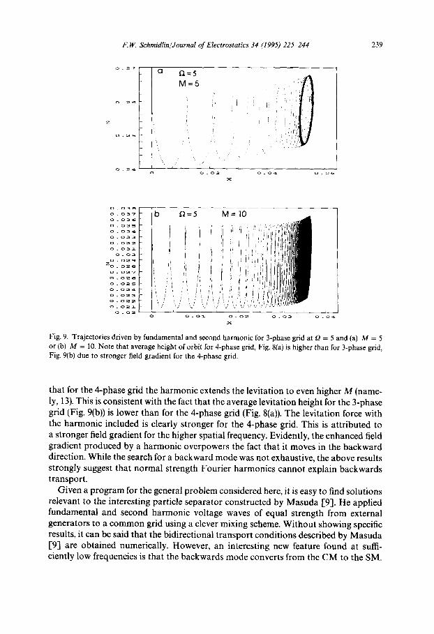
Fig. 9, Trajectories driven by fundamental and second harmonic for 3-phase grid at f2 = 5 and (a) M = 5 or (hi M = 10. Note that average height of orbit for 4-phase grid, Fig. 8(a) is higher than for 3-phase grid, Fig. 9(b) due to stronger field gradient for the 4-phase grid.
that for the 4-phase grid the harmonic extends the levitation to even higher M (name- ly, 13). This is consistent with the fact that the average levitation height for the 3-phase grid (Fig. 9(b)) is lower than for the 4-phase grid (Fig. 8(a)). The levitation force with the harmonic included is clearly stronger for the 4-phase grid. This is attributed to a stronger field gradient for the higher spatial frequency. Evidently, the enhanced field gradient produced by a harmonic overpowers the fact that it moves in the backward direction. While the search for a backward mode was not exhaustive, the above results strongly suggest that normal strength Fourier harmonics cannot explain backwards transport.
Given a program for the general problem considered here, it is easy to find solutions relevant to the interesting particle separator constructed by Masuda [9]. He applied fundamental and second harmonic voltage waves of equal strength from external generators to a common grid using a clever mixing scheme. Without showing specific results, it can be said that the bidirectional transport conditions described by Masuda [9] are obtained numerically. However, an interesting new feature found at suffi- ciently low frequencies is that the backwards mode converts from the CM to the SM.

240 F.W. Schmidlin/Journal o f Electrostatics 34 (1995) 225-244
o . 3 ( 2
D=.5 M = . I
o _ m
i
o i"b, , . . . . '~.
x
b
0 - - 1 . 5 - 1 . ~ - ~ . . 1 - o . 9 - o . 7 - o . s
Fig. 10. SM for idealized 4-phase grid perturbed by countermoving third harmonic. Jumps in (a) retrace the same 0 range in (b), proving particle stays on the same wave.
4.3. Harmonic perturbation of the SM
Toner moving on the 4-phase CTC is observed to move at the wave speed as tiny clouds [8]. The effect is attributed to scattering from the grid surface. The question of whether a countermoving harmonic can cause such scattering is now addressed by examining numerical results for £2 = 0.5 and variable M. The result for M = 0.1 is shown in Fig. 10(a). Note that the particle is forced to jump off the grid in this case, but it does so without losing the fundamental wave it rides on. This is proven with Fig. 10(b) which shows the samejumps plotted vs. the fundamental phase angle. Note that after the first cycle the particle retraces it path over the same small range phase angles within one wave.
Results for f2 = 0.5 and larger M are not illustrated here, but as M increases, the height of the jump rapidly decreases. For large enough M, the acceleration limit
(Ox/--M > 1.7) is exceeded and the particle motion converts to the CM. Reducing the frequency to f2 = 0.3, to enable recovery of the SM at M = 10 (typical of the toner studied experimentally), a jump height of only ,-~ 0.001 is found. Such a small effect would not be noticeable experimentally. It is thus concluded that a natural strength countermoving harmonic does not scatter sufficiently to contribute significantly to the cloud-like character of the toner that moves on the CTC. Scattering from the grid surface remains as the most plausible explanation for the behavior observed in those experiments.

F. I47, Schmidlin/Journal of Electrostatics 34 (1995) 225-244 241
5. Auxiliary conditions for special applications
In addition to producing the desired mode of transport, additional constraints must be considered for particular applications. The avoidance of cell dissociation in biological applications is discussed by Masuda [9]. The avoidance of corona for xerographic development is discussed in [8]. Often, however, the latter constraint is not satisfied. For example, an EC similar in form to that originally conceived by Masuda for removal of powder from the walls of a paint-spray booth has been proposed for use in imaging applications as well [13, 15]. Reasons why such attempts are best avoided warrant further discussion.
First of all, the issue of corona should be elaborated. For the conveyance of unused paint-spray, or bulk material from one reservoir to another in general, it may be necessary or even beneficial to generate corona while operating the transport device. Advantages that may ensue are charging of neutral powder to render it mobile and charging the powder to both polarities to enable storage in a container. This is in sharp contrast with the need to convey nearly unipolar toner to an imaging zone in xerography, and do so without disturbing the electric field of the latent image. To provide latitude for the generation of strong electric fields while avoiding corona, the CTC is designed [7, 8] to have as short a wavelength as practicable. This is inferred from the Paschen discharge law generalized to gaps between linear electrodes instead of between planar surfaces.
Another subtle but very important requirement for the xerographic development application concerns the magnitude of the average toner charge, called "tribo" in the xerographic industry. In xerography, a minimum value of Q is needed to assure an interaction with the field of the latent image (namely QE) that is larger than the noisy charge-independent short-range adhesive force (F,) that acts on toner. For typical toner, ,~ 10 gm in diameter, this normally leads to a minimum tribo ~ 10 gC per gram. This same requirement has repercussions in transport as well and leads to a minimum value of the parameter M. Note that from the definition of M, its primary factors are QEo and k. This is the same toner that is to be delivered to a latent image, and k is chosen by design to enable Eo to be made comparable to a latent image field. Insertion of typical or minimum values for these quantities into M leads to M ~ I. Thus, it is no accident that M ~ 10 in the CTC experiments [8]. By contrast, M ~ 0.1 in the experiments of MWK. Although MWK experimented with xerographic toner, it is evident that the charge of their toner was not independently adjusted or controlled. It was brushed onto the grid in a neutral or weakly charged condition.
In an indirect way, the above also explains the prevalence of sticking in the MWK experiments. Their QEo must be marginally ~ F , at best. Another condition in their experiments which further compounds the sticking problem is the use of low temporal frequencies. Adhesion to the grid may build in strength when the toner has time to rest on a grid while the wave catches up. Temporal growth of adhesion is a well-known attribute of toner.
It should finally be recalled that at low temporal frequencies toner sticking was also encountered in the CTC experiments [8], as manifested by toner accumulation on the grid. It is conceivable that the toner may have even moved at the time via hopping, but
242 F.W. Schmidlin/Journal of Electrostatics 34 (1995) 225-244
unfortunately, microscopic inspection of the motion on the CTC was not actually done under those circumstances. The objective at the time was to find conditions that maintained a clean grid and maximized the mass transport rate. By hindsight, it would be of great interest to carry out further traveling wave transport experiments at low frequencies. It would not only help clarify the conditions for achieving the HM vs. the SM; but also would prove to be an important tool for studying the elusive short-range adhesive force. The distance a particle hops after lift-off depends on the initial phase angle, and this, in turn, relates to the magnitude of the adhesive force. A measure- ment of the distribution of hop distances would thus shed light on the distribution of adhesive forces. To make such a study really useful, however, a challenge remains of finding a technique to measure the charge of a particle that makes a given hop.
6. Conclusions
The primary conclusions drawn from this revisit to the analysis of traveling wave particle transport are the following. • Particle sticking to the grid is essential to obtain the HM instead of the
SM. • A countermoving harmonic of normal (Fourier component) strength cannot ac-
count for backwards transport. It extends the normal forward mode to higher frequencies via enhanced levitation instead.
• Particle scattering from a transport grid precludes backwards transport in the manner predicted by perturbation theory.
• Scattering of particles in the SM by a countermoving Fourier harmonic cannot be an alternative explanation of the cloud-like character of transport observed with the CTC.
• Bidirectional transport consistent with Masuda's particle separator is found nu- merically when the harmonic wave is appropriately intensified.
• Bidirectional transport observed in the exploration of agricultural applications [5] are most likely the result of collective effects such as space charge rather than wave structure.
• Backwards transport may appear as an artifact in numerical analysis at large 12 and M if the incremental time steps are too large.
• The backwards movement of isolated particles observed experimentally [6] re- mains unexplained.
Notation
o A~
b
particle radius (= n V./V1) amplitude of the electric field for the first non-vanishing harmonic wave relative to the fundamental (= Q/6~la) particle mobility

F, W. Schmidlin/Journal of Electrostatics 34 (1995) 225-244 243
Eo G I k m
M n Q t
t'
vl (x, z) (x', z')
Greek letters
1/ 2 0 0e P ~7
~ o ~ fa
( = CV1) amplitude of the electric field for the fundamental wave (=mo/QEo) (= Q(e/eo = 1)/(16a2n(e - ~o)Eo)) (=2n/2) particle mass (=~oozr 2 = QEokm/(6rula)2), a dimensionless mass parameter number of harmonic wavelengths within the fundamental wavelength particle charge ( = t' O9o M1/2 = t'kb Eo) time amplitude of the fundamental component of the voltage wave (=(kx', kz')), dimensionless coordinates
coefficient of viscosity length of the fundamental wave ( = x - fat) phase position of particle relative to wave equilibrium phase position of a particle riding a wave coefficient of friction of particle against the grid (= m/6~qa) viscous relaxation time 1-8] (= QEok/m), see Ref. [8] (=(o~/tOo)/M 1/2 = (co/k)/(bEo)) wave speed/maximum drift speed
References
[1] S. Masuda, Apparatus for electric curtain of contact type, US Patent #3,778,678, 11 December 1973.
[2] S. Masuda, Booth for electrostatic powder painting with contact type electric curtain, US Patent # 3,801,869, 2 April 1974.
[31 S. Masuda, Electric curtain spray booth for powder coating, IEEE-IAS Annual Meeting, 1977, pp. 887-891.
[4] A.C. Yen and C.D. Hendricks, A planar electric curtain used as a device for the control and removal of particulate materials, J. Electrostatics, 4 (1978) 255-266.
[5"1 L.C. Weiss and D.P. Thibodeaux, Electrodynamic method for separating components, US Patent #4,534,856, 13 August 1985.
[6] S. Masuda, M. Washizu and M. lwadare, Separation of small particles suspended in liquid by non-uniform travelling field produced by three phase electric curtain device, IEEE-IAS Annual Meeting, Toronto, ON, Canada, 6-11 October 1985, pp. 1418-1423.
[7] F.W. Schmidlin, Development apparatus, US Patent #4,647,179, 3 March 1987. 1-8] F.W. Schmidlin, A new nonlevitated mode of traveling wave toner transport, IEEE Trans. Indust.
Appl., 257(3) (1991) 480-487. 1-9] S. Masuda, M. Washizu and I. Kawabata, Movement of blood cells in liquid by nonuniform traveling
field, IEEE Trans. Indust. Appl., (24) (1988) 217 222. 1-10] F.W. Schmidlin and N.R. Lindblad, Direct electrostatic printing apparatus and toner/developer
delivery system therefore, US Patent #4,743,926, 10 May 1988.
244 F.W. Schmidlin/Journal of Electrostatics 34 (1995) 225-244
[11] J.R. Melcher, E.P. Warren and R.H. Kotwal, Theory of pure-traveling-wave boundary-guided transport of tribo-electrified particles, Particle, Sci. Technol., 7 (1989) 1-21.
[12] J.R. Melcher, E.P. Warren and R.H. Kotwal, Theory for finite-phase boundary-guided transport of tribo-electrified particles, IEEE Trans. Indust. Appl., 25(5) (1989) 949-955.
[13] J.R. Melcher, E.P. Warren and R.H. Kotwal, Traveling-wave delivery of single component developer, IEEE Trans. Indust. Appl., 25(5) (1989) 956-961.
[14] W.H. Press, B.P. Flannery, S.A. Teukolsky and W.T. Vetterling, Numerical Recipes, Cambridge University Press, Cambridge, Chap. 15, 1986.
[15] M. Hosoya, T. Uehara and T. Nosaki, Recording apparatus using a toner-fog generated by electric fields applied to electrodes on the surface of the developer carrier, U.S. Patent # 4,568,955, 4 February 1986.